KR20170032928A - Apparatus for Grinding Side Edge of Thin Glass Cover - Google Patents
Apparatus for Grinding Side Edge of Thin Glass Cover Download PDFInfo
- Publication number
- KR20170032928A KR20170032928A KR1020150130303A KR20150130303A KR20170032928A KR 20170032928 A KR20170032928 A KR 20170032928A KR 1020150130303 A KR1020150130303 A KR 1020150130303A KR 20150130303 A KR20150130303 A KR 20150130303A KR 20170032928 A KR20170032928 A KR 20170032928A
- Authority
- KR
- South Korea
- Prior art keywords
- cover glass
- thin cover
- abrasive tape
- side edge
- tape
- Prior art date
Links
Images


Classifications
-
- B—PERFORMING OPERATIONS; TRANSPORTING
- B24—GRINDING; POLISHING
- B24B—MACHINES, DEVICES, OR PROCESSES FOR GRINDING OR POLISHING; DRESSING OR CONDITIONING OF ABRADING SURFACES; FEEDING OF GRINDING, POLISHING, OR LAPPING AGENTS
- B24B9/00—Machines or devices designed for grinding edges or bevels on work or for removing burrs; Accessories therefor
- B24B9/02—Machines or devices designed for grinding edges or bevels on work or for removing burrs; Accessories therefor characterised by a special design with respect to properties of materials specific to articles to be ground
- B24B9/06—Machines or devices designed for grinding edges or bevels on work or for removing burrs; Accessories therefor characterised by a special design with respect to properties of materials specific to articles to be ground of non-metallic inorganic material, e.g. stone, ceramics, porcelain
- B24B9/08—Machines or devices designed for grinding edges or bevels on work or for removing burrs; Accessories therefor characterised by a special design with respect to properties of materials specific to articles to be ground of non-metallic inorganic material, e.g. stone, ceramics, porcelain of glass
-
- B—PERFORMING OPERATIONS; TRANSPORTING
- B24—GRINDING; POLISHING
- B24B—MACHINES, DEVICES, OR PROCESSES FOR GRINDING OR POLISHING; DRESSING OR CONDITIONING OF ABRADING SURFACES; FEEDING OF GRINDING, POLISHING, OR LAPPING AGENTS
- B24B21/00—Machines or devices using grinding or polishing belts; Accessories therefor
- B24B21/04—Machines or devices using grinding or polishing belts; Accessories therefor for grinding plane surfaces
- B24B21/06—Machines or devices using grinding or polishing belts; Accessories therefor for grinding plane surfaces involving members with limited contact area pressing the belt against the work, e.g. shoes sweeping across the whole area to be ground
- B24B21/08—Pressure shoes; Pressure members, e.g. backing belts
-
- B—PERFORMING OPERATIONS; TRANSPORTING
- B24—GRINDING; POLISHING
- B24B—MACHINES, DEVICES, OR PROCESSES FOR GRINDING OR POLISHING; DRESSING OR CONDITIONING OF ABRADING SURFACES; FEEDING OF GRINDING, POLISHING, OR LAPPING AGENTS
- B24B21/00—Machines or devices using grinding or polishing belts; Accessories therefor
- B24B21/18—Accessories
Abstract
The present invention relates to a side edge polishing apparatus for a thin cover glass capable of precisely polishing a side edge of a thin thin cover glass using an abrasive tape. A side edge polishing apparatus for a thin cover glass according to the present invention comprises: a fixing unit for fixing a thin cover glass; and a fixing unit for fixing the thin cover glass to a belt-shaped material for polishing a side edge of the thin cover glass, An abrasive tape formed by attaching an abrasive material, an unwinder wound around the abrasive tape, a rewinder for rewinding the abrasive tape released from the unwinder, and a transfer path for the abrasive tape unwound from the unwinder and rewound to the rewinder And a pressing mechanism for moving the pressing member forward and backward to adjust the pressing force of the polishing tape with respect to the side edge of the thin cover glass.

Description
The present invention relates to a side edge polishing apparatus for a thin cover glass, and more particularly to a side edge polishing apparatus for a thin cover glass which can precisely polish the side edge of a thin thin cover glass using an abrasive tape.
A thin cover glass made of a tempered glass is used as an electronic device having a display such as a mobile device. The thin cover glass used in mobile devices is cut to a predetermined size and then used to polish the side. The side surface of the thin cover glass cut from the base material glass plate has a very high surface roughness.
If the side surface of the thin cover glass is not smooth, there arises a problem of safety and durability. If the side surface of the thin cover glass is not smooth and sharp, there is a problem that the user may be injured during use. Further, when the side surface of the thin cover glass is not smooth, the thin cover glass is damaged even in a small impact. That is, when the outer surface of the thin cover glass having a high brittleness such as tempered glass has a high surface roughness and sharpness, cracks are likely to be generated even in a small impact.
Because of such a problem, the thin cover glass is subjected to a process of polishing the edge side of the thinner cover glass with a polishing apparatus to smooth the surface. Conventionally, a thin cover glass is polished using a rotating polishing tool. Particularly, in the case of a thin cover glass used in a display device of a mobile device, it is necessary to process and polish the precise dimensions of the cover glass. In many cases, the final polishing process is performed manually by a person using an abrasive tool. In this case, the result of the polishing process is not constant and it is difficult to polish the wafer with the correct dimensions.
In addition, when a rotating abrasive tool is used, particles generated during the abrasion process collide with the surface of the thin cover glass to damage the surface. The roughness of the polishing tool is also changed during the polishing process, so that the time and degree of performing the polishing operation vary depending on the state of the tool. In addition, a hard polishing tool such as a polishing disk or a polishing wheel is liable to be adhered or worn to the surface of the polishing tool during polishing, so that it is necessary to dress it after a certain period of time or to replace it with another one.
On the other hand, chamfering the side edge of the thin cover glass to a predetermined shape instead of merely polishing the side surface and the side edge of the thin cover glass may improve the strength of the thin cover glass. In this case, the side edge of the thin cover glass must be chamfered in a standardized shape. However, there is a problem that it is difficult to control the shape of the chamfer of the side edge in the polishing apparatus using the conventional polishing tool.
SUMMARY OF THE INVENTION The present invention has been conceived to solve the problems as described above, and it is an object of the present invention to provide a method of polishing a side edge of a thin cover glass by using an abrasive tape having uniform surface roughness, It is an object of the present invention to provide a side edge polishing apparatus for a thin cover glass.
According to an aspect of the present invention, there is provided a side edge polishing apparatus for a thin cover glass, including: a fixing unit for fixing a thin cover glass; An abrasive tape having an abrasive material attached to a belt-like material to abrade the side edge of the thin cover glass in contact with the thin cover glass fixed to the fixed unit; An unwinder for winding the abrasive tape around; A rewinder for rewinding the abrasive tape released from the unwinder; A pressing member which is disposed on the conveying path of the abrasive tape to be unwound from the unwinder and rewinds to the rewinder to press the abrasive tape to the side edge of the thin cover glass; And a pressing mechanism for moving the pressing member in and out to adjust the pressing force of the polishing tape with respect to the side edge of the thin cover glass.
The side edge polishing apparatus of the thin cover glass according to the present invention has an advantage that the polishing operation of the thin cover glass can be performed accurately and quickly.
Further, in the side edge polishing apparatus of the thin cover glass according to the present invention, since the polishing tape is continuously released from the unwinder and rewound to the rewinder during the polishing operation, the abrasive particles generated during the polishing operation and the new polishing tape There is an advantage that the polishing work for the thin cover glass can be continued.
Further, the side edge polishing apparatus of the thin cover glass according to the present invention has an effect of uniformly maintaining the polishing quality for the thin cover glass.
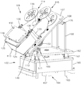
1 is a side view showing a side edge polishing apparatus of a thin cover glass according to an embodiment of the present invention.
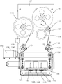
FIGS. 2 to 4 are perspective views illustrating a partial configuration of a side edge polishing apparatus of a thin cover glass according to an embodiment of the present invention.
5 is a plan view showing a polishing unit of a side edge polishing apparatus of a thin cover glass according to an embodiment of the present invention.
6 is a perspective view in which a part of the polishing unit of the side edge polishing apparatus of the thin cover glass according to the embodiment of the present invention is exploded.
7 is a view for explaining a process of polishing a side edge of a thin cover glass with a side edge polishing apparatus of a thin cover glass according to an embodiment of the present invention.
Hereinafter, a side edge polishing apparatus for a thin cover glass according to the present invention will be described in detail with reference to the drawings.
FIG. 1 is a side view showing a side edge polishing apparatus of a thin cover glass according to an embodiment of the present invention, and FIGS. 2 to 4 show a partial configuration of a side edge polishing apparatus for a thin cover glass according to an embodiment of the present invention. 5 is a plan view showing a polishing unit of a side edge polishing apparatus for a thin cover glass according to an embodiment of the present invention. FIG. 6 is a side view of a side edge polishing apparatus for polishing a side edge of a thin cover glass according to an embodiment of the present invention. Fig. 2 is a perspective view showing a part of the polishing unit of Fig.
1 to 6, a side
The
The
A
The
The
The pair of
The plurality of rotating
Although two sets of the
The
5 to 7, the pressing
The pressing
The operation of the
The
4 and 6, the
The
Referring to Figs. 1 to 4, the
The elevating
A
The engagement position of the
Referring to Fig. 1, the fixing
The fixed
When the side edge of the
It is possible to adjust the degree of polishing and the polishing dimension of the
The angle of the fixed
The
Hereinafter, the process of polishing the side edge of the
First, the
The polishing
The pressing force of the polishing
In addition, the fixing
The contact area and inclination of the polishing
As described above, the use of the side
Further, the polishing process of the
Although the preferred embodiment of the present invention has been described above, the scope of the present invention is not limited to the above-described and illustrated forms.
For example, the vibrating
It is also shown in the drawing that only the
In the drawings, the
Also, although the figure shows that the
Although the side
10: thin cover glass 100: polishing apparatus
101: polishing unit 102: supporting unit
103: fixed unit 104: conveying unit
105: control unit 107: support frame
108, 110: first and
113: abrasive tape 114: unwinder
115: Rewinder 116: Actuator
117: driving wheel 118: driving gear
119: drive
123: driven gear 125: support roller
126, 129: Guide roller 127:
128, 142: spring 130: rotating roller
131: pressure roller 132: driven pulley
133: belt 135: pressure member
138: Pressure device 140: Pressure sensor
141: sensing part 143: supporting plate
145: vibration unit 146: vibration frame
149: Guide bar 150: Fixing plate
152: cam mechanism 153: cam follower
154: connection rod 155: roller
156: cam wheel 157: cam
159, 167: motor 160: base
162: lifting member 164: lifting member
165: screw shaft 166: nut member
168: Support column 169: Support bar
170, 171: first and second connecting
176: Rotation mechanism
Claims (10)
An abrasive tape having an abrasive material attached to a belt-like material to abrade the side edge of the thin cover glass in contact with the thin cover glass fixed to the fixed unit;
An unwinder for winding the abrasive tape around;
A rewinder for rewinding the abrasive tape released from the unwinder;
A pressing member which is disposed on the conveying path of the abrasive tape to be unwound from the unwinder and rewinds to the rewinder to press the abrasive tape to the side edge of the thin cover glass; And
And a pressing mechanism for moving the pressing member to advance and retreat so as to adjust the pressing force of the polishing tape with respect to the side edge of the thin cover glass.
A pressure sensor installed on the pressing member so as to detect a pressing force of the polishing tape with respect to a side edge of the thin cover glass; And
And a control unit for receiving the detection signal of the pressure sensor and controlling the operation of the pressing mechanism.
Wherein the pressure sensor comprises a piezoelectric element which is compressed by a pressing force of the pressing member to press the polishing tape to generate a voltage.
And a vibration unit for applying a vibration to any one of the thin cover glass and the abrasive tape such that any one of the thin cover glass and the abrasive tape rubs against the other, Abrasive device.
The vibration unit includes:
A vibration frame,
A pair of support rollers provided on the vibrating frame so as to be disposed on both sides of the pressing member to support the abrasive tape,
A guide bar for slidably supporting the vibrating frame,
And a cam mechanism connected to the vibration frame to reciprocate the vibration frame along the guide bar.
A rotating roller provided on the conveying path of the abrasive tape so as to be rotatable in contact with one surface of the abrasive tape;
A pressing roller provided on a conveying path of the abrasive tape so as to press the abrasive tape with the rotating roller in contact with the other surface of the abrasive tape; And
And a driver for applying a rotational force to the rotating roller. ≪ Desc / Clms Page number 19 >
And a support frame for supporting the unwinder, the rewinder, and the pressing member so as to be inclined relative to the paper surface such that a surface of the abrasive tape contacting the side edge of the thin cover glass is inclined relative to the paper surface Wherein the edge of the side edge of the thin coverglass is polished.
Further comprising a support unit for supporting the support frame in such a manner that the support frame can be inclined so that the inclination of the surface of the abrasive tape contacting the side edge of the thin cover glass can be changed. .
A lifting member for supporting the support frame; And
And an elevating mechanism for elevating and lowering the elevating member.
Further comprising a transfer unit for moving the fixed unit such that a portion of the thin cover glass that contacts the abrasive tape is changed.
Priority Applications (1)
| Application Number | Priority Date | Filing Date | Title |
|---|---|---|---|
| KR1020150130303A KR20170032928A (en) | 2015-09-15 | 2015-09-15 | Apparatus for Grinding Side Edge of Thin Glass Cover |
Applications Claiming Priority (1)
| Application Number | Priority Date | Filing Date | Title |
|---|---|---|---|
| KR1020150130303A KR20170032928A (en) | 2015-09-15 | 2015-09-15 | Apparatus for Grinding Side Edge of Thin Glass Cover |
Publications (1)
| Publication Number | Publication Date |
|---|---|
| KR20170032928A true KR20170032928A (en) | 2017-03-24 |
Family
ID=58500409
Family Applications (1)
| Application Number | Title | Priority Date | Filing Date |
|---|---|---|---|
| KR1020150130303A KR20170032928A (en) | 2015-09-15 | 2015-09-15 | Apparatus for Grinding Side Edge of Thin Glass Cover |
Country Status (1)
| Country | Link |
|---|---|
| KR (1) | KR20170032928A (en) |
Cited By (4)
| Publication number | Priority date | Publication date | Assignee | Title |
|---|---|---|---|---|
| KR20190006796A (en) * | 2017-07-11 | 2019-01-21 | 주식회사 케이씨텍 | Circulating moving unit and substrate polishing apparatus comprising the same |
| KR20200020293A (en) * | 2018-08-17 | 2020-02-26 | 주식회사 일각금속 | Multi-axis grinding device for automatically polishing the outer surface of the mobile phone case |
| KR20220076664A (en) * | 2020-12-01 | 2022-06-08 | 주식회사 에이치비테크놀러지 | Apparatus for Polishing Defects Using Polishing Tapes |
| KR20220076695A (en) * | 2020-12-01 | 2022-06-08 | 주식회사 에이치비테크놀러지 | Polishing Tape Case |
Citations (3)
| Publication number | Priority date | Publication date | Assignee | Title |
|---|---|---|---|---|
| KR20080013746A (en) | 2006-08-08 | 2008-02-13 | 소니 가부시끼 가이샤 | Polishing method and polishing device |
| KR101025263B1 (en) | 2008-11-28 | 2011-03-29 | 주식회사 엘지실트론 | Tape polisher |
| KR20130114955A (en) | 2012-04-10 | 2013-10-21 | 엘지디스플레이 주식회사 | Method of polishing a thin glass |
-
2015
- 2015-09-15 KR KR1020150130303A patent/KR20170032928A/en not_active Application Discontinuation
Patent Citations (3)
| Publication number | Priority date | Publication date | Assignee | Title |
|---|---|---|---|---|
| KR20080013746A (en) | 2006-08-08 | 2008-02-13 | 소니 가부시끼 가이샤 | Polishing method and polishing device |
| KR101025263B1 (en) | 2008-11-28 | 2011-03-29 | 주식회사 엘지실트론 | Tape polisher |
| KR20130114955A (en) | 2012-04-10 | 2013-10-21 | 엘지디스플레이 주식회사 | Method of polishing a thin glass |
Cited By (4)
| Publication number | Priority date | Publication date | Assignee | Title |
|---|---|---|---|---|
| KR20190006796A (en) * | 2017-07-11 | 2019-01-21 | 주식회사 케이씨텍 | Circulating moving unit and substrate polishing apparatus comprising the same |
| KR20200020293A (en) * | 2018-08-17 | 2020-02-26 | 주식회사 일각금속 | Multi-axis grinding device for automatically polishing the outer surface of the mobile phone case |
| KR20220076664A (en) * | 2020-12-01 | 2022-06-08 | 주식회사 에이치비테크놀러지 | Apparatus for Polishing Defects Using Polishing Tapes |
| KR20220076695A (en) * | 2020-12-01 | 2022-06-08 | 주식회사 에이치비테크놀러지 | Polishing Tape Case |
Similar Documents
| Publication | Publication Date | Title |
|---|---|---|
| KR100405415B1 (en) | Double Side Grinding Machine for Sheet Metal Workpiece | |
| TWI278926B (en) | Apparatus and method of polishing periphery of device wafer | |
| EP2008769B1 (en) | Polishing apparatus and polishing method | |
| JP5051613B2 (en) | Glass plate end grinding machine | |
| KR20170032928A (en) | Apparatus for Grinding Side Edge of Thin Glass Cover | |
| US8393935B2 (en) | Polishing apparatus | |
| US6261959B1 (en) | Method and apparatus for chemically-mechanically polishing semiconductor wafers | |
| KR101587731B1 (en) | Exposure apparatus | |
| JP2012020390A (en) | Platy member polishing device | |
| KR20190059570A (en) | Apparatus for cutting substrate | |
| KR100819178B1 (en) | The interior super-finishing device and control system thereof | |
| KR101144978B1 (en) | Protective film attaching apparatus | |
| JP5352216B2 (en) | Wafer peripheral part polishing equipment | |
| KR20150055369A (en) | Die Cutting Press Machine and Method for Cutting Film with the Same | |
| KR101615533B1 (en) | Cassette Type Grinding Device Using Grinding Tape | |
| KR102067984B1 (en) | Apparatus for cutting substrate | |
| TW201938320A (en) | Polishing device | |
| JP2005335002A (en) | Squeegee polishing device | |
| JP5758680B2 (en) | Deburring device | |
| KR102067985B1 (en) | Apparatus for cutting substrate | |
| JP2001328051A (en) | Polishing method and device for edge portion of workpiece | |
| JP2006181697A (en) | Surface polishing device and method | |
| JP4078183B2 (en) | Device wafer peripheral polishing equipment | |
| KR200424875Y1 (en) | A plane polishing device using polishing film | |
| KR200424873Y1 (en) | The interior super-finishing device |
Legal Events
| Date | Code | Title | Description |
|---|---|---|---|
| A201 | Request for examination | ||
| E902 | Notification of reason for refusal | ||
| E601 | Decision to refuse application |