JP2012020390A - Platy member polishing device - Google Patents
Platy member polishing device Download PDFInfo
- Publication number
- JP2012020390A JP2012020390A JP2010161887A JP2010161887A JP2012020390A JP 2012020390 A JP2012020390 A JP 2012020390A JP 2010161887 A JP2010161887 A JP 2010161887A JP 2010161887 A JP2010161887 A JP 2010161887A JP 2012020390 A JP2012020390 A JP 2012020390A
- Authority
- JP
- Japan
- Prior art keywords
- polishing belt
- polishing
- belt
- pressure contact
- contact member
- Prior art date
- Legal status (The legal status is an assumption and is not a legal conclusion. Google has not performed a legal analysis and makes no representation as to the accuracy of the status listed.)
- Pending
Links
- 238000005498 polishing Methods 0.000 title claims abstract description 304
- 241000276425 Xiphophorus maculatus Species 0.000 title abstract 4
- 230000007246 mechanism Effects 0.000 claims abstract description 80
- 239000000853 adhesive Substances 0.000 claims description 3
- 230000001070 adhesive effect Effects 0.000 claims description 3
- 230000001360 synchronised effect Effects 0.000 claims description 2
- 239000000463 material Substances 0.000 abstract description 5
- 230000001133 acceleration Effects 0.000 abstract 1
- NJPPVKZQTLUDBO-UHFFFAOYSA-N novaluron Chemical compound C1=C(Cl)C(OC(F)(F)C(OC(F)(F)F)F)=CC=C1NC(=O)NC(=O)C1=C(F)C=CC=C1F NJPPVKZQTLUDBO-UHFFFAOYSA-N 0.000 description 9
- 230000002093 peripheral effect Effects 0.000 description 6
- 238000010586 diagram Methods 0.000 description 5
- 238000004804 winding Methods 0.000 description 3
- 238000000034 method Methods 0.000 description 2
- 238000000926 separation method Methods 0.000 description 2
- 239000003381 stabilizer Substances 0.000 description 2
- RYGMFSIKBFXOCR-UHFFFAOYSA-N Copper Chemical compound [Cu] RYGMFSIKBFXOCR-UHFFFAOYSA-N 0.000 description 1
- JOYRKODLDBILNP-UHFFFAOYSA-N Ethyl urethane Chemical compound CCOC(N)=O JOYRKODLDBILNP-UHFFFAOYSA-N 0.000 description 1
- 238000005299 abrasion Methods 0.000 description 1
- 239000006061 abrasive grain Substances 0.000 description 1
- 230000001174 ascending effect Effects 0.000 description 1
- 230000005540 biological transmission Effects 0.000 description 1
- 230000008602 contraction Effects 0.000 description 1
- 229910052802 copper Inorganic materials 0.000 description 1
- 239000010949 copper Substances 0.000 description 1
- 230000007850 degeneration Effects 0.000 description 1
- 238000000605 extraction Methods 0.000 description 1
- 230000006698 induction Effects 0.000 description 1
- 238000009434 installation Methods 0.000 description 1
- 238000004080 punching Methods 0.000 description 1
- 239000004065 semiconductor Substances 0.000 description 1
- 229920002379 silicone rubber Polymers 0.000 description 1
- 239000004945 silicone rubber Substances 0.000 description 1
- 230000000087 stabilizing effect Effects 0.000 description 1
Images


Landscapes
- Finish Polishing, Edge Sharpening, And Grinding By Specific Grinding Devices (AREA)
Abstract
Description
本発明は、半導体装置の組立に用いられるリードフレームやプリント基板、銅板等の板状部材の表面研磨装置に関するものである。 The present invention relates to a surface polishing apparatus for a plate member such as a lead frame, a printed circuit board or a copper plate used for assembling a semiconductor device.
板状部材の表面研磨装置として、駆動装置により回転駆動する駆動ローラと、回動自在な1以上の遊動ローラと、前記ローラ間に掛架されて走行する研磨ベルトと、この研磨ベルトの非研磨面(同ベルトの裏面側)に押圧力を付与する押圧機構と、この押圧機構の下方に設けた、研磨ベルトの研磨面(同ベルトの表面側)に対向配置した被研磨材料である板状部材を保持する保持台とを備えているものが知られている。 As a surface polishing device for a plate-like member, a driving roller that is rotationally driven by a driving device, one or more idler rollers that are rotatable, a polishing belt that runs while being hung between the rollers, and a non-polishing of the polishing belt A pressing mechanism that applies a pressing force to the surface (the back side of the belt) and a plate-like material to be polished that is disposed below the pressing mechanism and faces the polishing surface of the polishing belt (the front side of the belt) What is provided with the holding stand which hold | maintains a member is known.
このように研磨ベルトを用いた研磨装置は、その研磨ベルトの掛架方式によりエンドレス式とオープンリール式に大別される。エンドレス式は、駆動ローラと1以上の遊動ローラとに研磨ベルトをエンドレスとして掛架してなるもので、オープンリール式は、駆動ローラと1以上の遊動ローラとは別個に、研磨ベルトを巻き回した研磨ベルト供給リールと、送給される研磨ベルトを巻取る研磨ベルト巻取りリールとを用いて研磨ベルトをオープンリールとして掛架してなるものである。 The polishing apparatus using the polishing belt as described above is roughly classified into an endless type and an open reel type depending on the method of hanging the polishing belt. In the endless type, the polishing belt is suspended endlessly between the driving roller and one or more idle rollers. In the open reel type, the abrasive belt is wound separately from the drive roller and one or more idle rollers. The polishing belt is hung as an open reel using the polishing belt supply reel and the polishing belt take-up reel that winds up the supplied polishing belt.
例えば、エンドレス式としては、特許文献1に、「送材通路側に配備された踏圧パッドと、該踏圧パッドの両側に配置される案内ローラを含む複数のロールによって構成されて無端サンディングベルトが掛け渡されるベルト案内機構とを備えたベルト研削装置を、送材装置に対設してなるベルトサンダー機において、前記踏圧パッドと、ベルト案内機構とを装着フレームに付装して一体的に連結し、該装着フレームに付装した垂直方向の支軸と、本体フレーム側に付装した垂直方向の支軸間に回動リンクを介装し、該装着フレームを往復駆動装置により往復付勢して、本体フレーム側の支軸を中心として送材方向と交叉する方向へ連続往復揺動させたことを特徴とするベルトサンダー機」が開示されている。 For example, as an endless type, Japanese Patent Application Laid-Open No. H10-228561 discloses that “an endless sanding belt is formed by a plurality of rolls including a treading pressure pad disposed on the feeding path and guiding rollers disposed on both sides of the treading pad”. In a belt sander machine in which a belt grinding device provided with a belt guide mechanism to be delivered is provided to a feeding device, the stepping pressure pad and the belt guide mechanism are attached to a mounting frame and integrally connected. A rotating link is interposed between the vertical support shaft attached to the mounting frame and the vertical support shaft attached to the main body frame, and the mounting frame is reciprocally urged by a reciprocating drive device. Further, a belt sander machine characterized in that it is continuously reciprocally swung in a direction intersecting with the feeding direction around a spindle on the main body frame side is disclosed.
一方、オープンリール式としては、特許文献2に、「板状部材を保持可能な保持台と、該板状部材の研磨面を研磨可能な研磨テープと、該研磨テープを移送可能なテープ移送機構と、該研磨テープのテープ面を板状部材の研磨面に圧接可能な圧接機構と、該研磨テープを平面運動させるテープ平面運動機構とからなり、上記テープ平面運動機構は、並列状に縦設された一対の支持軸と、該一対の支持軸のうち、一方の支持軸を回転させる回転用モータ及び該一方の支持軸と他方の支持軸との間に介装され、該一方の支持軸の回転により該他方の支持軸を回転させるためのベルト伝動機構とからなる回転機構と、該一対の支持軸の下端部間に架設される圧接部材と、該各支持軸と圧接部材との間にそれぞれ介装される偏心輪機構とを具備してなることを特徴とする板状部材研磨装置」が開示されている。
On the other hand, as an open reel type,
また、特許文献3には、「機台上に立設された門形の機体と、該機台上に配置され、板状部材を水平保持可能な保持台と、該保持台を該門形の機体内を通過する水平送り運動させる送り機構と、該板状部材の被研磨面である上面を研磨可能な研磨テープと、該研磨テープの表面を該板状部材の被研磨面に対して対面状に移送可能なテープ移送機構と、該研磨テープの裏面を下方に押圧して該研磨テープの表面を該板状部材の被研磨面に圧接可能な圧接部材とからなり、上記機体に上記圧接部材を吊下状に上記押圧方向に上昇下降案内可能な移動案内機構を設け、該圧接部材を常時下方に押圧可能であって上記研磨テープの表面と上記板状部材の被研磨面との圧接力を調節可能な圧接調節機構を設け、該下降動作の途中から該研磨テープの裏面を押圧して研磨テープの表面を該板状部材の被研磨面に圧接している該吊下状の圧接部材を上昇動作させて該研磨テープの圧接を解除する離反機構を設けてなることを特徴とする板状部材研磨装置」が開示されている。
Further,
さらに、特許文献4には、「ベッド上にワークを載置した製品台を設け、前記ベッド上の左右両側に研磨ベルトフレームを立設せしめると共に、この各研磨ベルトフレームの上部に、研磨ベルトが巻き取られた研磨ベルト繰り出しリールとこの研磨ベルト繰り出しリールから繰り出された研磨ベルトを巻き取る研磨ベルト巻き取りリールを設け、前記ベッド上における前記研磨ベルトフレームの両内側に左右軸フレームを立設せしめ、この左右軸フレームに対して左右方向へ移動可能な前後軸フレームを設け、この前後軸フレームに前後方向へ移動可能な移動体を設け、この移動体に上下方向へ移動自在な押圧子を設けてなることを特徴とするバリ取り装置」が開示されている。
Furthermore,
なお、前述のエンドレス式では、それぞれのローラの配置距離によって研磨ベルトの長さ(全長)が制約されるが、オープンリール式では、研磨ベルト供給リールと研磨ベルト巻取りリールの大きさに制約されるものの研磨ベルトを長くできることから、研磨作業に伴う砥粒の摩滅や脱落などによる研磨ベルトの交換頻度を少なくできる。したがって、近年ではオーブンリール式が多く用いられるようになっている。 In the above-mentioned endless type, the length (full length) of the polishing belt is limited by the arrangement distance of each roller, but in the open reel type, the size of the polishing belt supply reel and the polishing belt take-up reel is limited. However, since the polishing belt can be lengthened, it is possible to reduce the frequency of replacement of the polishing belt due to abrasion or dropping of abrasive grains accompanying the polishing operation. Therefore, in recent years, an oven reel type is often used.
特許文献1に開示されたベルトサンダー機は、高速走行中の研磨ベルトを回動リンクを用いてその走行方向と直交する方向へ往復揺動させることで、その揺動成分と被研磨材の走行との合成により研磨作業を行うものであり、エンドレス式であることと相まって研磨ベルトの磨耗が早く、その耐用性、作業効率に問題がある。 The belt sander disclosed in Patent Document 1 reciprocally swings a polishing belt running at a high speed in a direction perpendicular to the traveling direction using a rotating link, so that the swing component and the material to be polished travel. In combination with the endless type, the polishing belt wears quickly and there is a problem in its durability and work efficiency.
特許文献2に開示された板状部材研磨装置は、圧接部材を偏心運動させながら研削するものであり、その動きに追従するために研磨ベルトに余裕代が不可欠であり、不足すると研磨ベルトが破断する虞もあるため、その余裕代確保のためには所定回数の研磨作業終了後に、送り用モータの正逆転駆動による研磨ベルトの往復動による調整作業が必要であり、このため作業効率の低下を招くなどの問題がある。
The plate-shaped member polishing apparatus disclosed in
特許文献3に開示された板状部材研磨装置は、テープ移送機構及びその関連機構と圧接部材およびその昇降機構とを分離して構成することで、昇降部分の高速昇降を可能とするものであるが、巻取りモータと張架用モータとによるテープ移送機構等と圧接部材等との連携部分は、圧接調節機構と移動案内機構に設けた離反機構を組み合わせて研磨作業を行うことから圧接調整用シリンダーと離反用シリンダーとの昇降範囲の整合性を図らなければならない外、傾動許容機構や揺振機構をそれぞれに配置するなど構成が複雑となる問題がある。
The plate-like member polishing apparatus disclosed in
特許文献4に開示されたバリ取り装置は、板状部材の平面部と凸部であるバリとを区分して、バリのみを研磨除去し、平面部には研磨ベルトが接触しないように、水平方向に走行する研磨ベルトとその下方の製品台とを平行に配置し、X−Y−Z軸方向に移動自在なフローティング機能を有する押圧子がバリに当接したときにのみ研磨作業を行うものであるから、押圧子を設けた移動体を高速で移動させることが難しい外、研磨ベルトを停止状態で研磨作業を行うため作業能率の向上は難しいなどの問題がある。
The deburring device disclosed in
本発明は、板状部材と研磨ベルトとの押圧面を均一に接触させて、均一平面に仕上げると共に、押圧を自動調整することで、最適な研磨条件で板状部材を効率的に研磨できる板状部材研磨装置を提供することを目的とするものである。 The present invention provides a plate capable of efficiently polishing a plate-like member under optimum polishing conditions by bringing the pressing surface of the plate-like member and the polishing belt into uniform contact with each other to finish the flat surface and automatically adjusting the pressure. An object of the present invention is to provide an apparatus for polishing a shaped member.
本発明の板状部材研磨装置は、研磨ベルト供給リールから研磨ベルトを誘導する案内ロール群を経て研磨ベルト巻取りリールに至る研磨ベルト誘導機構と、
研磨ベルトを誘導する案内ロール群中の第1研磨ベルト送りローラ及びこれと離間させて水平方向に対向配置した第2研磨ベルト送りローラと併せて、研磨ベルト供給リール及び研磨ベルト巻取りリールを同期駆動する研磨ベルト送りモータを設けた研磨ベルト駆動機構と、
研磨ベルトの駆動方向と直交する方向に揺動する揺動機構に圧接部材降下用電動シリンダーを設けると共に、前記圧接部材降下用電動シリンダーのロッドの先端部に研磨ベルトの駆動方向と直交する方向に配置した圧接部材を研磨ベルトの駆動方向に沿って回動自在に設けた押圧機構と、
押圧機構の下方に位置する板状部材を固着して上載する保持台、及び前記保持台を研磨ベルトの駆動方向と平行な方向に往復動させる保持台送り用電動シリンダーを設けた保持台移送機構とを備え、
前記圧接部材降下用電動シリンダーを電流比制御によって制御することを特徴とするものである。
The plate member polishing apparatus of the present invention includes a polishing belt guiding mechanism that reaches a polishing belt take-up reel through a guide roll group that guides the polishing belt from the polishing belt supply reel,
The polishing belt supply reel and the polishing belt take-up reel are synchronized with the first polishing belt feed roller in the guide roll group that guides the polishing belt and the second polishing belt feed roller that is spaced apart from the first polishing belt feed roller and disposed horizontally. An abrasive belt drive mechanism provided with an abrasive belt feed motor for driving;
A pressure contact member lowering electric cylinder is provided in a swing mechanism that swings in a direction perpendicular to the driving direction of the polishing belt. A pressing mechanism in which the arranged pressure contact member is rotatably provided along the driving direction of the polishing belt;
A holding table transfer mechanism provided with a holding table on which a plate-like member positioned below the pressing mechanism is fixed and mounted, and a holding table feeding electric cylinder for reciprocating the holding table in a direction parallel to the driving direction of the polishing belt And
The electric cylinder for lowering the pressure contact member is controlled by current ratio control.
本発明において前記押圧機構は、前記研磨ベルト誘導機構及び研磨ベルト駆動機構を設けた機枠の内方に設けた副機枠に回動軸を研磨ベルトの駆動方向と平行に伸びるように設けると共に、前記回動軸に本体取付部材を研磨ベルトの駆動方向と直交する方向に伸びかつ下方に垂下するように設け、前記本体取付部材に圧接部材降下用電動シリンダーをそのロッドが下方を向くように固定し、前記ロッドの先端部に前記圧接部材を設けることで、研磨ベルトの駆動方向と直交する方向に揺動自在とすることができる。 In the present invention, the pressing mechanism is provided in a sub-machine frame provided inside the machine frame provided with the polishing belt guiding mechanism and the polishing belt driving mechanism so that the rotation shaft extends in parallel with the driving direction of the polishing belt. The body mounting member is provided on the rotating shaft so as to extend in a direction perpendicular to the driving direction of the polishing belt and hang downward. The electric cylinder for lowering the pressure contact member is disposed on the body mounting member so that the rod faces downward. By fixing and providing the pressure contact member at the tip of the rod, the rod can be swung freely in a direction perpendicular to the driving direction of the polishing belt.
また、前記保持台移送機構の保持台の上面には粘着性を有するシートを固着することができる。 Further, an adhesive sheet can be fixed to the upper surface of the holding table of the holding table transfer mechanism.
本発明の板状部材研磨装置は、圧接部材が板状部材の反りに追従して機械的に揺動することから板状部材と研磨ベルトの研削面とを均一に接触させて、板状部材を均一平面に仕上げることができると共に、電流比制御によって、圧接部材の押圧力の加減を被研削面の状況に応じて自動的に調整できることから、最適な研磨条件で板状部材を効率的に研磨できる。 In the plate member polishing apparatus of the present invention, since the pressure contact member mechanically swings following the warpage of the plate member, the plate member and the grinding surface of the polishing belt are uniformly brought into contact with each other. Can be finished in a uniform plane, and the pressure ratio of the pressure contact member can be automatically adjusted according to the condition of the surface to be ground by current ratio control, so that the plate-like member can be efficiently used under optimum polishing conditions. Can be polished.
以下、図面に示す実施例に基づいて本発明の実施の形態を説明する。 Hereinafter, embodiments of the present invention will be described based on examples shown in the drawings.
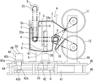
図1は本発明の板状部材の研磨装置の正面一部断面図である。同図において1で示すものは研磨ベルトである。11は研磨ベルト供給リールであり、研磨ベルト1の実巻きリールである。これから引き出されたあるいは移送される研磨ベルト1は、圧接部材(ロール状のコンタクトホイール)7の周面にその裏側が接触し、その表側の研磨面は板状部材としてのリードフレーム50の被研磨面と対向配置され、最終的に空リールである研磨ベルト巻取りリール12へ引き込まれあるいは移送される。すなわち、本発明の研磨装置はオープンリール式の研磨装置である。
FIG. 1 is a partial front sectional view of a plate member polishing apparatus of the present invention. In the figure, reference numeral 1 denotes an abrasive belt.
研磨装置の基盤46上に所要の高さで設けた台座45の一方部にリール受け用片持架台48と台座45の概ね中央部に研磨装置本体の機枠47を立設して、研磨ベルト1の誘導機構A及び駆動機構Bを設けている。
A
また、機枠47の内方に設けた後述する副機枠30に圧接部材7を備えた押圧機構Cを併設している。なお、圧接部材7は押圧機構Cの構成要素であると共に誘導機構Aの構成要素でもある。
In addition, a pressing mechanism C provided with a
さらに、リードフレーム50を上載する保持台40を台座45の他方端部から圧接部材7の下方部を通過して往復動させ、保持台40をリードフレーム50の載置、取出し位置から研摩作業位置まで移動自在とする保持台移送機構Dを基盤46上に設けている。
Further, the holding table 40 on which the
以下、研磨ベルト誘導機構A、研磨ベルト駆動機構B、押圧機構C及び保持台移送機構Dの具体的な構成を説明する。 Hereinafter, specific configurations of the polishing belt guiding mechanism A, the polishing belt driving mechanism B, the pressing mechanism C, and the holding table transfer mechanism D will be described.
まず、研磨ベルト誘導機構Aについて説明する。 First, the polishing belt guiding mechanism A will be described.
図1に示すように、機枠47には、その上方部に研磨ベルト1を誘導する案内ロール2、3及び研磨ベルト1を案内すると共に張力を付与する研磨ベルトテンションローラ5を、その下方部に研磨ベルト1を引続いて誘導する案内ロール6、8、10を、それらの中間部に機枠47の他方端部近傍に第1研磨ベルト送りローラ4、その一方端部近傍に第2研磨ベルト送りローラ9を、それらの軸部を軸受で支持して回動自在に配置している。そして研磨ベルト送りローラ4と第2研磨ベルト送りローラ9の配置位置の中間部かつ低位の位置に独立した圧接部材7を配置している。
As shown in FIG. 1, the
各案内ロール2、3、6、8、10と研磨ベルトテンションローラ5、研磨ベルト送りローラ4、9と、圧接部材7、並びに機枠47の一方部の外側に設けているリール受け用片持架台48に軸支している研磨ベルト供給リール11及び研磨ベルト巻取りリール12のそれぞれの回動軸は平行に配置している。
Each
研磨ベルトテンションローラ5はその軸受部を摺動自在に支持し、その一端部を機枠47に固定した引っ張りバネ5aにより常時上向きの力を付与している。なお、本実施例では研磨ベルトテンションローラ5として軸受内蔵型ローラを用いており、図2にその張力付与機構の一例を示している。同図中5bは機枠開口部、5cは研磨ベルトテンションローラ5の両端部に内蔵された軸受、5dは誘導部材、5eはその案内部材、5fは機枠47と誘導部材5dとの固定部材、5gは研磨ベルトテンションローラ5の軸部と引っ張りバネ5aとの固定部材、5hは機枠47と引っ張りバネ5aとの固定部材を示す。
The polishing
図3は、研磨ベルト誘導機構Aの模式図である。同図に示すように、研磨ベルト供給リール11の下方から引き出された研磨ベルト1は、案内ロール2によって、水平方向に案内ロール3へ誘導される。案内ロール3に誘導される研磨ベルト1は水平方向から下方へ誘導され、その下方転向点において第1研磨ベルト送りローラ4によって上方へ誘導され、次いで、研磨ベルト1は、その上方転向点において研磨ベルトテンションローラ5によって下方へ誘導され、下方部の案内ロール6を経由して、圧接部材7の周面部の下方面に摺接しながら移動し、案内ロール8によって上方へ誘導された後、その上方転向点において、第2研磨ベルト送りローラ9によって下方へ誘導され、下方部の案内ロール10を経由して、研磨ベルト1は研磨ベルト巻取りリール12の上方から引き込まれる。
FIG. 3 is a schematic diagram of the polishing belt guiding mechanism A. FIG. As shown in the figure, the polishing belt 1 pulled out from below the polishing
研磨ベルト供給リール11から研磨ベルト巻取りリール12に至るまでの研磨ベルト1は、研磨ベルトテンションローラ5による上向きの力を受けて、常時、一定の張力を付与された状態にある。
The polishing belt 1 from the polishing
なお、研磨ベルト供給リール11及び研磨ベルト巻取りリール12からの研磨ベルト1の引き出し、引き込み位置はそれらのリール11、12の回動方向により規定される。例えば、実施例のように上下位置に配置した場合、それぞれ同一方向に回転するときは同一位置(上方であれば両者とも上方)、それぞれ対向方向に回転するときは相対位置(一方が上方であれば、他方は下方)となる。
Note that the position where the polishing belt 1 is pulled out and retracted from the polishing
次に、研磨ベルト駆動機構Bについて説明する。 Next, the polishing belt drive mechanism B will be described.
図4は、研磨ベルト駆動機構Bの模式図である。同図に示すように、研磨ベルト送りモータ20の出力軸には出力プーリ21が固定されている。なお、研磨ベルト送りモータ20は、図1に示したように機枠47の最上部に固定されている。
FIG. 4 is a schematic diagram of the polishing belt drive mechanism B. As shown in FIG. As shown in the figure, an
研磨ベルト送りモータ20の駆動力を確実に伝動させるために、出力プーリ21の垂直下方に第1研磨ベルト送りローラ4の第1駆動プーリ21aを配置する。これは実施例において、研磨ベルト送りモータ20の配置位置から第1研磨ベルト送りローラ4が直近の位置にあることによるものである。
In order to reliably transmit the driving force of the polishing
なお、先に図3に示したように、研磨ベルト1に張力を付与するために、研磨ベルト1は、案内ロール3と研磨ベルトテンションローラ5との間はU字形状、研磨ベルト送りローラ4と案内ロール6との間は逆U字形状に誘導される。
As shown in FIG. 3, the polishing belt 1 is U-shaped between the
図4に戻って、研磨ベルト1のU字形状の底部位置に配置された第1研磨ベルト送りローラ4の胴部の両端部の軸部には、一方部に研磨ベルト送りモータ20の出力プーリ21と対応する第1駆動プーリ21aと他方部に第2駆動プーリ22を固定している。
Returning to FIG. 4, the shafts at both ends of the body portion of the first polishing
第2研磨ベルト送りローラ9の胴部の両端部の軸部には、他方部に前記第2駆動プーリ22と対応する第3駆動プーリ23と一方部に第4駆動プーリ24と第5駆動プーリ26とを並設して固定している。第4駆動プーリ24は、研磨ベルト供給リール11の取付軸48aに固定した第6駆動プーリ25に対応させている。そして第5駆動プーリ26は研磨ベルト巻取りリール12の取付軸48bに固定した第7駆動プーリ27に対応させている。
The shafts at both ends of the body of the second polishing
前記研磨ベルト送りモータ20の出力軸に固定された出力プーリ21と第1駆動プーリ21aとに第1駆動ベルト21bを掛け回している。また、研磨ベルト送りローラ4の軸部の他方部に固定した第2駆動プーリ22と第2研磨ベルト送りローラ9の他方部に固定した第3駆動プーリ23とに第2駆動ベルト22aを掛け回している。さらに、第2駆動ベルト送りローラ9の軸部の一方部に固定した第4駆動プーリ24と研磨ベルト供給リール11の取付軸48aに固定した第6駆動プーリ25とに第3駆動ベルト24aを掛け回すと共に、第4駆動プーリ24と併設して固定している第5駆動プーリ26と研磨ベルト巻取りリール12の取付軸48bに固定した第7駆動プーリ27とに第4駆動ベルト26aを掛け回している。
A
このような各部のプーリと駆動ベルトとの組合せ構成により、研磨ベルト送りモータ20の回動により、その駆動力を受けて第1研磨ベルト送りローラ4、第2研磨ベルト送りローラ9、研磨ベルト供給リール11及び研磨ベルト巻取りリール12を回動させる。これにより、研磨ベルト1は駆動(引き出し、引き込み、走行、移送される状態を示す。)される。
By such a combined configuration of the pulleys and the driving belts of the respective parts, the first polishing
なお、第1駆動ベルト21bの張力調整は、研磨ベルト送りローラ4を軸支する両軸受部を、一対の摺動枠により摺動自在に支持し、その一端部を機枠47に、他端部をその軸受部に固定した張力調整ネジ20a(図1参照)による両者の間隔調整により行うほか、研磨ベルト送りモータ20を機枠47に固定する台座と機枠47の取り付け座との間を可動式として調整するようにしても良い。
The tension of the
また、研磨ベルト供給リール11と研磨ベルト巻取りリール12との回転方向は、図示しない制御機器盤(制御装置を組み込んだもの)からの制御信号を受けた研磨ベルト送りモータ20の回転方向が切り替わることで決められる。この回転方向の切り替えは、研磨ベルト1の研磨性能が有用な間の研磨ベルト供給リール11に収納された研磨ベルト1が引き出されて研磨ベルト巻取りリール12に全て巻き取られた後や、リードフレーム50の研磨状況の観察から逆方向からの研磨が必要なときなどに、自動あるいは作業者の手動により行われる。
Further, the rotation directions of the polishing
前述した研磨ベルト供給リール11及び研磨ベルト巻取りリール12の回転はそれぞれ同一方向としているので、第3駆動ベルト24aをたすき掛け(駆動ベルトをその中間部で交差させる)としている。なお、これはいずれか一方をたすき掛けとすることで対応できるので、第4駆動ベルト26a側をたすき掛けとしても良い。
Since the polishing
ここで、研磨ベルト供給リール11と研磨ベルト巻取りリール12は、案内ロール2、3、6、8、10、研磨ベルトテンションローラ5や研磨ベルト送りローラ4、9がその両軸部を軸受部で軸支しているのと異なり、一方側のみの片持形式として、リール受け用片持架台48に設けた上下個別の軸受部に各リール11、12の取付軸48a、48bを回動自在に軸支している。また、各リール11、12のそれぞれの中空心材部とリール受け用片持架台48に軸支された取付軸48a、48bとに噛合い部を設け、回り止めとし、さらに取付軸48a、48bの他方端部には前記リール11、12の抜け留め具を設けている。
Here, the polishing
なお、前記研磨ベルトテンションローラ5は、研磨ベルト送りモータ20の駆動力を確実に第1研磨ベルト送りローラ4を介して、研磨ベルト1に伝達するために一定の張力を付与するものであるが、研磨作業中の押圧部材7とリードフレーム50との押圧力の変動に影響を受けることがあるため、第1研磨ベルト送りローラ4及び第2研磨ベルト送りローラ9の周速度を、研磨ベルト供給リール11及び研磨ベルト巻取りリール12の周速度よりも遅く設定することで、第3駆動ベルト24a、第4駆動ベルト26aの滑りを利用し研磨ベルト1に一定の張力が掛かるようにしている。その周速度の差は、いずれも同径である第1研磨ベルト送りローラ4の第2駆動プーリ22及び第2研磨ベルト送りローラ9の第3駆動プーリ23の直径を、第2研磨ベルト送りローラ9の一方部のいずれも同径である第4駆動プーリ24と対応するベルト供給リール11の第6駆動プーリ25及び第5駆動プーリ26と対応する研磨ベルト巻取りリール12の第7駆動プーリ27の直径よりも小径とすることで生じさせている。
The polishing
以上のとおり、研磨ベルト1は、常時一定の張力を付与されることで、研磨ベルト供給リール11、研磨ベルト巻取りリール12、第1研磨ベルト送りローラ4及び第2研磨ベルト送りローラ9が研磨ベルト送りモータ20の駆動力の伝達を受けて弛みを生じることなく駆動されることから、研磨ベルト1の駆動方向が正逆何れの方向でも安定した駆動ができる。
As described above, the polishing belt 1 is always given a constant tension, so that the polishing
研磨ベルト1を交換する際は、後述する圧接部材降下用電動シリンダー35のシリンダーロッド36を縮退限度まで後退(配置位置から上昇となる。)させて、圧接部材7と研磨ベルト1との接触を解消後、研磨ベルト供給リール11と研磨ベルト巻取りリール12とをそれぞれ固定している取付軸48a、48bの先端部の抜け留め具を開放し、取付軸48a、48bから引く抜くことで行う。取り付け時は逆動作により行う。また、研磨ベルト1の引き出し方向は、正逆制御するため、交換時には研磨ベルト供給リール11と研磨ベルト巻取りリール12の何れか一方側に研磨ベルト1が巻き取られている状態にあり、研磨作業時は、研磨ベルト1の引き出し側が研磨ベルト供給リール、巻取り側が研磨ベルト巻取りリールとなる。
When exchanging the polishing belt 1, a
次に、押圧機構Cについて説明する。 Next, the pressing mechanism C will be described.
図1を参照すると、本実施例では研磨ベルト1を用いた研磨装置の押圧機構Cとして、軸付ウレタンローラから構成する圧接部材7を設けると共に、圧接部材7を保持台40に押し当てるために待機位置(研磨作業前、または研磨作業終了後の保持台40表面から上方へ十分から離間した位置)から保持台40の上面に当接する位置(所要の研磨圧を保持できる位置)まで昇降させる圧接部材降下用電動シリンダー35を設けている。具体的には圧接部材7を機枠47の内方に設けた後述する副機枠30に配置することで押圧機構Cを構成している。
Referring to FIG. 1, in this embodiment, as a pressing mechanism C of a polishing apparatus using the polishing belt 1, a pressing
図5は研磨ベルトの押圧機構Cの模式図で、(a)は平面図、(b)は側面図である。同図に示すように、副機枠30は、研磨ベルトの駆動方向と直交方向に配置し、水平に所定間隔で機枠47の上方部に固定した一対の梁部材31、31と、この一対の梁部材31、31の長さ方向の中心部に設けられ、軸孔の向きを梁部材31、31の長さ方向と直交方向とした軸受32、32と、この軸受32、32に軸支した回動軸33とから構成している。すなわち、回転軸33は研磨ベルトの駆動方向と平行に伸びるように配置されている。 なお、副機枠30は、前述の研磨ベルト送りローラ4と第2研磨ベルト送りローラ9との水平方向の中間部の非干渉位置に配置される。
5A and 5B are schematic views of the polishing belt pressing mechanism C, where FIG. 5A is a plan view and FIG. 5B is a side view. As shown in the figure, the
回動軸33の長手方向にその幅方向が直交する本体取付部材34を垂設固定する。すなわち、本体取付部材34は、回動軸33に、研磨ベルトの駆動方向と直交する方向に伸びかつ下方に垂下するように固定する。これにより本体取付部材34は回動軸33を中心に研磨ベルトの駆動方向と直交方向に揺動自在となる。この本体取付部材34が本発明の揺動機構を構成する。そして、本体取付部材34に、シリンダーロッド36の先端部が下向きとなるように圧接部材降下用電動シリンダー35を固定部材34aを介して固定する。なお、本体取付部材34が自然吊下状態のときの回動軸33の垂直方向中心線とシリンダーロッド36の中心軸線とが一致又は平行となるように配置することが好ましい。
A main
圧接部材降下用電動シリンダー35の本体の梁部材31、31と平行方向の側線上に案内部材37を突出して設け、この案内部材37に沿って昇降すると共にその下端部を水平方向にL字状に延伸し、シリンダーロッド36の先端部を固定してシリンダーロッド36の昇降に従動する誘導部材38を摺動自在に設ける。
A
誘導部材38のL字状部のシリンダーロッド36との固定部を中心部としてその下面部に、研磨ベルトの駆動方向と直交する方向に設けた延伸部材38aの両先端部を下方へ垂直に曲折した軸受台部38b、38bを形成する。この軸受台部38b、38bの下端面にそれぞれ軸受38c、38cを固定する。さらに両軸受38c、38cに圧接部材7の両端部の軸部を軸支し、当接する研磨ベルトの駆動方向に追従して回動自在とする。
The L-shaped portion of the
また、前記本体取付部材34と延伸部材38aとにそれぞれ固定支持部材を設け、両者の間に引っ張りスプリング(バランサー)39を配置し、電源が落ちるなどして、圧接部材降下用電動シリンダー35の制動機能が失われてもシリンダーロッド36が圧接部材7等の重量により急激に下降することを防ぐようにしている。
Further, a fixing support member is provided on each of the main
前述のように、本体取付部材34は回動軸33に垂設固定されて、揺動自在に吊下げているので、研磨ベルト1の駆動方向と直交方向がその揺動方向となり、前記圧接部材降下用電動シリンダー35により昇降する圧接部材7は研磨ベルト1の駆動方向には揺動しない。
As described above, the main
圧接部材7は、シリンダーロッド36の進出により、誘導され移送されている研磨ベルトを裏面側から押し下げ、所定の押圧力により研磨作業を行う。そして、その裏面側から押し下げられた研磨ベルトは、その下方に移送されている保持台40に上載されているリードフレーム50の被研磨面と対向する。保持台40を研磨ベルトの下方に移送するために、図1で示したように保持台移送機構Dを台座45及び基盤46に設けている。
The
次に、保持台移送機構Dについて説明する。 Next, the holding table transfer mechanism D will be described.
台座45には、前述のとおり、その一方部に立設したリール受け用片持架台48とその概ね中央部に研磨装置本体の機枠47を立設し、その他方部から機枠47下方部を通過して往復動する保持台40を配置している。
As described above, the
保持台40は、その他方端部から機枠47の下方部を通過し、リール受け用片持架台48の手前に達する一軸スライダー(リニアガイド)43の可動台板43aに支承された可動台座43bに固定している。一軸スライダー43は台座45の上面に配置している。
The holding
一軸スライダー43を固定した台座45の下方部に一軸スライダー43と平行に保持台送り用電動シリンダー41を一方端部寄りのリール受け用片持架台48を支持する台座45の下方位置の基盤46上に設ける。
On the base 46 in the lower position of the
保持台送り用電動シリンダー41のロッド42の先端部に固定した取付部材42aと一軸スライダー43の可動台板43aとを連結部材44で一体化し、保持台送り用電動シリンダー41のシリンダーロッド42の進退に同期して一軸スライダー43の可動台板43aを進退させることで保持台40を板状部材であるリードフレーム50の載置、取出し位置から研摩作業位置まで移動自在としている。
The
保持台40は、研磨ベルト1の駆動方向と直交する方向にその長手方向を配置するが、研磨ベルト1の幅寸法と板状部材50の長軸方向の寸法を考慮して配置される。
The holding table 40 is arranged in the longitudinal direction in a direction orthogonal to the driving direction of the polishing belt 1, and is arranged in consideration of the width dimension of the polishing belt 1 and the major axis direction of the plate-
また、保持台40上でのリードフレーム50の取扱い作業区域から、保持台送り用電動シリンダー41の通常縮退位置において、保持台40上のリードフレーム50の全面の研磨を完了できる位置から多少余裕を有するようにそのシリンダーロッド42の進退距離を設定する。
Further, from the work work area of the
さらに、保持台40の上面には粘着性を有し高い摩擦係数を持つシート49(例えば、シリコーンラバー)を固着して、リードフレーム50をその表面に押し付けるように載置するとその粘着面に固着されて、研摩作業時にリードフレーム50がその摩擦係数により保持台40上で動かないようにすることができる。
Further, a sheet 49 (for example, silicone rubber) having adhesiveness and a high friction coefficient is fixed to the upper surface of the holding
なお、図1中42bで示すものはシリンダーロッド42の進退動作を安定させるための移動安定具であり、基盤46上に配置した軌条上を走行する車輪を用いているが、ロッド42の先端部を保持台40と同様の一軸スライダーで支承することもできる。
In addition, what is shown by 42b in FIG. 1 is a movement stabilizer for stabilizing the forward / backward movement of the
以上の構成において、待機位置の保持台40上面のシート49上に被研磨材である短冊状のリードフレーム50の長手方向を研摩ベルト1の駆動方向と直交する方向に載置後、保持台送り用電動シリンダー41を駆動し、押圧機構Cの下方側へ保持台40を移送すると共に、研磨ベルト送りモータ20を駆動して研磨ベルト1を駆動、移送させる。
In the above configuration, after the longitudinal direction of the strip-shaped
保持台40が押圧機構Cの下方部に達すると圧接部材降下用電動シリンダー35が作動し、シリンダーロッド36が伸長(下降)し、圧接部材7により研磨ベルト1に押圧力が設定電流値を示すバイナリデータの数値制御に従って加えられ、保持台40上面の摩擦係数の高いシート49により固着されたリードフレーム50のバリの除去と共にその表面研磨が連続して行われる。
When the holding
研磨作業は、保持台40上のリードフレーム50の短辺(幅)が一方側端から他方側端まで圧接部材7から離脱するまでの間行われ、リードフレーム50が圧接部材7の研磨域通過後、もしくは初期設定時間経過後、圧接部材降下用電動シリンダー35の作動方向が逆転し、そのシリンダーロッド36が縮退(上昇)し、圧接部材7による研磨ベルト1の押圧が消失する。そして研磨済みのリードフレーム50と研磨ベルト1とが離間した後、保持台送り用電動シリンダー41がそのシリンダーロッド42を伸長する方向へ作動し、保持台40は最初の載置位置へ戻り、研磨済みのリードフレーム50を取り出し、次のリードフレームを載置することで、研摩作業を繰り返す。
The polishing operation is performed until the short side (width) of the
リードフレームはパンチプレスにより打ち抜き加工されることから、その一面に立ち上がった状態でバリが生じるため、一方向からの研磨の場合、バリの一部が研摩方向に倒れることがあるが、その場合は保持台40を最初の載置位置に戻すときに押圧機構Cを下降させたまま、すなわち、研磨作業状態としておくことで再度研磨作業を行う。この際に、研磨ベルト1の移送方向を逆転させるとさらに確実に倒れたバリを除去することができる。 Since the lead frame is punched by a punch press, burrs are generated when the lead frame stands up, so in the case of polishing from one direction, a part of the burrs may fall in the polishing direction. When the holding table 40 is returned to the initial placement position, the polishing operation is performed again while the pressing mechanism C is lowered, that is, in the polishing operation state. At this time, if the transfer direction of the polishing belt 1 is reversed, the burrs that have fallen down can be removed more reliably.
また、打ち抜き加工時にリードフレーム50の長手(長軸)方向に反りが生じていても、押圧機構Cは前述のとおり回動軸33に軸支しているので、圧接部材7はリードフレーム50の反りの方向に揺動し、常にリードフレーム50の被研削面に均一な圧接力を加えることができる。
Even if the
リードフレーム50の研磨に際しては、事前に、リードフレーム50の加工後の表面状況に応じた移動距離、往復回数、移動速度、研磨速度などを研磨装置の制御装置にその状況に対応した設定データを図示しない制御機器盤で入力することで、保持台送り用電動シリンダー41を自動制御することができるので、最適な保持台40の往復動を行わせることが可能である。
Prior to polishing the
また、リードフレーム50の厚み、リードフレーム50の保持台40に載置したときの高さ位置のバラツキなどの変動要因により、充分な研磨を行えないことがある。これに対応するために、圧接部材7が平均的なリードフレーム50に最適な押付力により当接したときの圧接部材降下用電動シリンダー35の電流値を設定値として制御装置に設定電流制御値としてバイナリデータ(0〜255)の数値を入力することで、圧接部材降下用電動シリンダー35の圧接力を、電流値が上下(0〜100%)した際に、設定電流値に復帰させる電流比制御を行い、リードフレーム50に均一に接触するように調整する。このような電流比制御を行うことで、安定稼働を保ち、研摩精度を向上できるので、リードフレーム表面の平滑化および表面の仕上げを良好なものとする研磨を行うことができる。
Further, sufficient polishing may not be performed due to factors such as the thickness of the
なお、設定電流値は、被研磨面の状況で多少の変動があるためロット毎に設定の変更を行うことが好ましい。また、研磨作業の効率向上には、被研磨面への研磨ベルトの押圧だけでなく、研磨ベルトの移送速度、保持台の送り速度も重要な要素であるが、本発明における駆動源は、電動式であり、研磨ベルト送りモータ、保持台送り用電動シリンダーについても、その回転数、伸縮速度の調整を併せて行うことは容易である。 It should be noted that the setting current value is preferably changed for each lot because there is some variation in the condition of the surface to be polished. Further, in order to improve the efficiency of the polishing operation, not only the pressing of the polishing belt to the surface to be polished but also the transfer speed of the polishing belt and the feed speed of the holding base are important factors. It is easy to adjust the rotational speed and expansion / contraction speed of the polishing belt feed motor and the holding table feed electric cylinder.
A.研磨ベルト誘導機構
1;研磨ベルト
2;案内ロール
3;案内ロール
4;第1研磨ベルト送りローラ
5;研磨ベルトテンションローラ
5a;引張りバネ
6;案内ロール
7;圧接部材(コンタクトホイール)
8;案内ロール
9;第2研磨ベルト送りローラ
10;案内ロール
11;研磨ベルト供給リール
12;研磨ベルト巻取りリール
B.研磨ベルト駆動機構
20;研磨ベルト送りモータ
20a;張力調整ネジ
21;出力プーリ
21a;第1駆動プーリ
21b;第1駆動ベルト
22;第2駆動プーリ
23;第3駆動プーリ
22a;第2駆動ベルト
24;第4駆動プーリ
25;第6駆動プーリ
24a;第3駆動ベルト
26;第5駆動プーリ
26a;第4駆動ベルト
27;第7駆動プーリ
C.押圧機構
30;副機枠
31;梁部材
32;軸受
33;回動軸
34;本体取付部材
35;圧接部材降下用電動シリンダー
36;シリンダーロッド
37;案内部材
38;誘導部材
38a;延伸部材
38b;軸受台部
38c;軸受
39;引っ張りスプリング(バランサー)
D.保持台移送機構
40;保持台
41;保持台送り用電動シリンダー
42;シリンダーロッド
42a;取付部材
42b;移動安定具
43;一軸スライダー(リニアガイド)
43a;可動台板
43b;可動台座
44;連結部材
45;台座
46;基盤
47;機枠
48;リール受け用片持架台
48a;取付軸
48b;取付軸
49;シート
50;板状部材(リードフレーム)
A. Abrasive belt guide mechanism 1;
8; guide
B. Polishing
D. Holding
43a;
Claims (3)
研磨ベルトを誘導する案内ロール群中の第1研磨ベルト送りローラ及びこれと離間させて水平方向に対向配置した第2研磨ベルト送りローラと併せて、研磨ベルト供給リール及び研磨ベルト巻取りリールを同期駆動する研磨ベルト送りモータを設けた研磨ベルト駆動機構と、
研磨ベルトの駆動方向と直交する方向に揺動する揺動機構に圧接部材降下用電動シリンダーを設けると共に、前記圧接部材降下用電動シリンダーのロッドの先端部に研磨ベルトの駆動方向と直交する方向に配置した圧接部材を研磨ベルトの駆動方向に沿って回動自在に設けた押圧機構と、
押圧機構の下方に位置する板状部材を固着して上載する保持台、及び前記保持台を研磨ベルトの駆動方向と平行な方向に往復動させる保持台送り用電動シリンダーを設けた保持台移送機構とを備え、
前記圧接部材降下用電動シリンダーを電流比制御によって制御することを特徴とする板状部材研磨装置。 A polishing belt guide mechanism from the polishing belt supply reel to the polishing belt take-up reel via a guide roll group for guiding the polishing belt;
The polishing belt supply reel and the polishing belt take-up reel are synchronized with the first polishing belt feed roller in the guide roll group that guides the polishing belt and the second polishing belt feed roller that is spaced apart from the first polishing belt feed roller and disposed horizontally. An abrasive belt drive mechanism provided with an abrasive belt feed motor for driving;
A pressure contact member lowering electric cylinder is provided in a swinging mechanism that swings in a direction orthogonal to the polishing belt drive direction, and the tip of the rod of the pressure contact member lowering electric cylinder is orthogonal to the polishing belt drive direction. A pressing mechanism in which the arranged pressure contact member is rotatably provided along the driving direction of the polishing belt;
A holding table transfer mechanism provided with a holding table on which a plate-like member positioned below the pressing mechanism is fixed and mounted, and a holding table feeding electric cylinder for reciprocating the holding table in a direction parallel to the driving direction of the polishing belt And
The plate member polishing apparatus, wherein the pressure contact member lowering electric cylinder is controlled by current ratio control.
Priority Applications (1)
| Application Number | Priority Date | Filing Date | Title |
|---|---|---|---|
| JP2010161887A JP2012020390A (en) | 2010-07-16 | 2010-07-16 | Platy member polishing device |
Applications Claiming Priority (1)
| Application Number | Priority Date | Filing Date | Title |
|---|---|---|---|
| JP2010161887A JP2012020390A (en) | 2010-07-16 | 2010-07-16 | Platy member polishing device |
Publications (1)
| Publication Number | Publication Date |
|---|---|
| JP2012020390A true JP2012020390A (en) | 2012-02-02 |
Family
ID=45775085
Family Applications (1)
| Application Number | Title | Priority Date | Filing Date |
|---|---|---|---|
| JP2010161887A Pending JP2012020390A (en) | 2010-07-16 | 2010-07-16 | Platy member polishing device |
Country Status (1)
| Country | Link |
|---|---|
| JP (1) | JP2012020390A (en) |
Cited By (9)
| Publication number | Priority date | Publication date | Assignee | Title |
|---|---|---|---|---|
| JP5525072B1 (en) * | 2013-01-21 | 2014-06-18 | 日本金銭機械株式会社 | Discoid polishing machine |
| CN105397597A (en) * | 2015-10-26 | 2016-03-16 | 长安大学 | Full-automatic multi-stage integrated metallographical grinding and polishing machine |
| KR20160132548A (en) * | 2015-05-11 | 2016-11-21 | 김종식 | An Apparatus for Grinding a Lead Frame and a Method for Grinding a Lead Frame |
| KR101892894B1 (en) * | 2018-01-25 | 2018-08-28 | 김종식 | An Apparatus for Grinding a Surface of a Lead Frame |
| WO2020155428A1 (en) * | 2019-01-29 | 2020-08-06 | 福建青拓特钢技术研究有限公司 | Energy-saving metallographic sample grinding machine |
| CN111546223A (en) * | 2020-06-12 | 2020-08-18 | 广东博科数控机械有限公司 | Walking type thin-wall component grinding and polishing equipment |
| CN112497017A (en) * | 2020-11-26 | 2021-03-16 | 庄阳辉 | Metal plate machining workbench |
| CN113458891A (en) * | 2021-08-18 | 2021-10-01 | 广州珠江恺撒堡钢琴有限公司 | Automatic polishing device for core felt of piano hammer head |
| CN113478349A (en) * | 2021-06-02 | 2021-10-08 | 谭万国 | Printed circuit board processing equipment with chip removing mechanism |
-
2010
- 2010-07-16 JP JP2010161887A patent/JP2012020390A/en active Pending
Cited By (12)
| Publication number | Priority date | Publication date | Assignee | Title |
|---|---|---|---|---|
| JP5525072B1 (en) * | 2013-01-21 | 2014-06-18 | 日本金銭機械株式会社 | Discoid polishing machine |
| KR20160132548A (en) * | 2015-05-11 | 2016-11-21 | 김종식 | An Apparatus for Grinding a Lead Frame and a Method for Grinding a Lead Frame |
| KR101696875B1 (en) | 2015-05-11 | 2017-01-16 | 김종식 | An Apparatus for Grinding a Lead Frame and a Method for Grinding a Lead Frame |
| CN105397597A (en) * | 2015-10-26 | 2016-03-16 | 长安大学 | Full-automatic multi-stage integrated metallographical grinding and polishing machine |
| CN105397597B (en) * | 2015-10-26 | 2017-07-11 | 长安大学 | A kind of full-automatic metallographical polishing machine of multistage integratedization |
| KR101892894B1 (en) * | 2018-01-25 | 2018-08-28 | 김종식 | An Apparatus for Grinding a Surface of a Lead Frame |
| WO2020155428A1 (en) * | 2019-01-29 | 2020-08-06 | 福建青拓特钢技术研究有限公司 | Energy-saving metallographic sample grinding machine |
| CN111546223A (en) * | 2020-06-12 | 2020-08-18 | 广东博科数控机械有限公司 | Walking type thin-wall component grinding and polishing equipment |
| CN112497017A (en) * | 2020-11-26 | 2021-03-16 | 庄阳辉 | Metal plate machining workbench |
| CN113478349A (en) * | 2021-06-02 | 2021-10-08 | 谭万国 | Printed circuit board processing equipment with chip removing mechanism |
| CN113458891A (en) * | 2021-08-18 | 2021-10-01 | 广州珠江恺撒堡钢琴有限公司 | Automatic polishing device for core felt of piano hammer head |
| CN113458891B (en) * | 2021-08-18 | 2024-05-31 | 广州珠江恺撒堡钢琴有限公司 | Automatic polishing device for hammer core felt of steel musical instrument |
Similar Documents
| Publication | Publication Date | Title |
|---|---|---|
| KR960002336B1 (en) | Machine for polishing surface of glass plate | |
| CN101306513A (en) | Single groove single race bearing super precise grinding machine | |
| JP5889471B1 (en) | Surface treatment equipment | |
| CN204603996U (en) | A kind of modified lines double side polishing machine | |
| CN101497174B (en) | Cambered surface sanding and polishing machine | |
| KR20170032928A (en) | Apparatus for Grinding Side Edge of Thin Glass Cover | |
| JP2011240449A (en) | Wire saw | |
| US6220940B1 (en) | Micro-finishing apparatus | |
| JP2018158428A (en) | Wire saw and cutting processing method | |
| CN201371406Y (en) | Machine for grinding and polishing arc surface | |
| CN109153103B (en) | with finishing equipment | |
| CN212385216U (en) | Automatic burnishing machine of centreless excircle | |
| CN113798955A (en) | Small curvature free-form surface profiling grinding device and grinding method thereof | |
| CN108035136A (en) | A kind of novel textile fabric Scissoring device | |
| KR102112550B1 (en) | Apparatus for polishing of table roller | |
| JP2000288888A (en) | Deburring device | |
| JP2007160491A (en) | Polishing tape vibration polishing method and apparatus | |
| CN206567943U (en) | A kind of automatic floating steel plate edging device | |
| CN112265089B (en) | Bamboo sheet wire drawing edging device is used in processing of bamboo summer sleeping mat | |
| US3071904A (en) | Strip sharpening method | |
| CN201728870U (en) | Automatic rolling, reel-changing and breaking device of bag machine | |
| CN214418493U (en) | A large size bar polishing equipment | |
| CN211029445U (en) | A kind of automatic machining equipment | |
| CN116460729A (en) | A surface wire drawing machine capable of continuous feeding | |
| CN204976249U (en) | Polishing device |