JP2005335002A - Squeegee polishing device - Google Patents
Squeegee polishing device Download PDFInfo
- Publication number
- JP2005335002A JP2005335002A JP2004155847A JP2004155847A JP2005335002A JP 2005335002 A JP2005335002 A JP 2005335002A JP 2004155847 A JP2004155847 A JP 2004155847A JP 2004155847 A JP2004155847 A JP 2004155847A JP 2005335002 A JP2005335002 A JP 2005335002A
- Authority
- JP
- Japan
- Prior art keywords
- squeegee
- polishing
- angle
- unit
- polishing apparatus
- Prior art date
- Legal status (The legal status is an assumption and is not a legal conclusion. Google has not performed a legal analysis and makes no representation as to the accuracy of the status listed.)
- Pending
Links
- 238000005498 polishing Methods 0.000 title claims abstract description 257
- 230000007246 mechanism Effects 0.000 claims abstract description 146
- 238000007639 printing Methods 0.000 claims abstract description 58
- 238000003825 pressing Methods 0.000 claims abstract description 45
- 238000007650 screen-printing Methods 0.000 claims abstract description 6
- 238000001514 detection method Methods 0.000 claims description 9
- 239000000463 material Substances 0.000 description 13
- 238000000034 method Methods 0.000 description 7
- 230000000694 effects Effects 0.000 description 3
- 239000002184 metal Substances 0.000 description 3
- 230000005540 biological transmission Effects 0.000 description 2
- 230000003028 elevating effect Effects 0.000 description 2
- IDCBOTIENDVCBQ-UHFFFAOYSA-N TEPP Chemical compound CCOP(=O)(OCC)OP(=O)(OCC)OCC IDCBOTIENDVCBQ-UHFFFAOYSA-N 0.000 description 1
- 239000003082 abrasive agent Substances 0.000 description 1
- 238000005452 bending Methods 0.000 description 1
- 238000004140 cleaning Methods 0.000 description 1
- 238000007796 conventional method Methods 0.000 description 1
- 238000010586 diagram Methods 0.000 description 1
- 238000004519 manufacturing process Methods 0.000 description 1
- 230000003287 optical effect Effects 0.000 description 1
- 239000002245 particle Substances 0.000 description 1
Images




Landscapes
- Grinding And Polishing Of Tertiary Curved Surfaces And Surfaces With Complex Shapes (AREA)
Abstract
Description
本発明は、例えばカラープラズマディスプレイの表示面に対するスクリーン印刷用のスキージを自動研磨するスキージ研磨装置に関する。 The present invention relates to a squeegee polishing apparatus that automatically polishes a screen printing squeegee for a display surface of a color plasma display, for example.
例えばカラープラズマディスプレイの表示面に印刷を行う方法としてスクリーン印刷による方法がある。 For example, there is a screen printing method as a method for printing on the display surface of a color plasma display.
スクリーン印刷は、メッシュ状のスクリーン上に滴下したペースト状インキをスキージを用いて刷り込むことによって表示面に所定の印刷を行う印刷技術である。 Screen printing is a printing technique that performs predetermined printing on a display surface by printing paste-like ink dropped on a mesh-like screen using a squeegee.
ここで、スキージは弾力性を有するものであり、該スキージの一端部を挟持するようにして固定する金属製のスキージホルダとともに、スキージユニットを構成する。 Here, the squeegee has elasticity, and constitutes a squeegee unit together with a metal squeegee holder that is fixed so as to sandwich one end of the squeegee.
スキージは、一般にゴム又はゴムに類似して弾力性を有する材料で製作されており、印刷時、スクリーンに対してエッジ部を利用してインクを刷り込むため、使用することによりエッジ部が摩耗する。 The squeegee is generally made of rubber or a material having elasticity similar to rubber, and the ink is imprinted on the screen using the edge portion during printing, so that the edge portion is worn by use.
そのため、スキージは、例えば一定の使用回数毎にスキージ研磨装置により研磨することによって、エッジ部を所望の形状に維持する必要がある。 Therefore, the edge of the squeegee needs to be maintained in a desired shape by polishing the squeegee with a squeegee polishing device, for example, every certain number of uses.
しかし、研磨後のスキージの被研磨面、特にエッジ部に傷、ばり、欠けがあると、印刷のときに印刷すじや印刷むらが発生する要因となる。 However, if there are scratches, flashes, or chips on the polished surface of the squeegee after polishing, particularly on the edge portion, it becomes a factor that causes print streaks or uneven printing.
したがってスキージ研磨装置においては、スキージのエッジ面に傷、ばり、欠けが発生しないよう研磨することが重要な要素の一つとなっている。 Therefore, in the squeegee polishing apparatus, it is one of the important elements to polish so that scratches, flashes, and chips are not generated on the edge surface of the squeegee.
従来のスキージ研磨装置として特願2003−358413の技術を図10に示す。 FIG. 10 shows a technique of Japanese Patent Application No. 2003-358413 as a conventional squeegee polishing apparatus.
スキージユニット10は、金属製のスキージホルダ12と、このスキージホルダ12に一端部が挟持されるようにして固定された弾力性を有するスキージ11から構成される。
The
スキージユニット10は、スキージホルダ12をスキージ研磨装置のホルダ固定用シリンダ100によりクランプすることによって該研磨装置に固定される。
The
研磨砥石101は円盤状を成し、回転動作によりスキージ11の研磨を行う。
The
また、研磨砥石101は装置上部に配置され、上下方向、前後方向(図10では左右方向)およびスキージ11の長手方向(図10では奥行き方向)にそれぞれ移動可能に設けられている。
Further, the
また、エッジ研磨砥石102は研磨砥石101と相対して装置上部に配置される。
The
スキージホルダ12をホルダ固定用シリンダ100により固定した後、起動スイッチを押すと、昇降可能な研磨砥石101が原点位置より下降を開始する。やがて、研磨砥石101の最下面と同一高さに配置された検知センサ103によりスキージ11の端面を検知すると、研磨砥石101の下降は停止する。
After the
つまり、研磨砥石101はスキージの端面の高さまで下降して停止する。その状態で、研磨砥石101によりスキージ11の端面を研磨する。
That is, the
このようにしてスキージ11の端面の研磨を終了した後、研磨砥石101は待機位置に移動し、サポートバー104がスキージ11の側面に当接して支持した状態で、エッジ研磨砥石102がスキージ11のエッジ面を研磨する。
After the polishing of the end face of the
ところで、上記において説明した従来の技術は、研磨砥石101によりスキージ11の端面を研磨する際に発生するスキージ11のエッジ部のバリ・欠けを、エッジ研磨砥石102により除去することを目的としている。
By the way, the conventional technique described above is intended to remove burrs and chips at the edge of the
また、サポートバー104がスキージ11の側面を保持することにより、エッジ研磨砥石102がスキージ11に当接する際に生じるスキージ11の変形を抑え、エッジ部を均一な研磨状態にするという効果が得られている。
Further, since the
しかし、印刷時には、スキージ11はスクリーンに対し一定の角度(スキージ角度)を保持して接するが、この角度は材料・条件によりまちまちである。
However, during printing, the
しかも、印刷時には、スキージ11はスクリーンと接する際に、印圧を加えられており、スキージ11は変形する。このため印刷条件の違いにより被印刷物に接するスキージ11のエッジ部の角度もまちまちである。よって、スキージ11のエッジ部を理想の研磨状態にする為には、印刷で設定されたスキージ角度とともにスキージ11の変形まで考慮し、エッジ部を研磨する必要がある。
Moreover, during printing, the
しかしながら、特願2003−358413の方法では、エッジ部の研磨状態を均一にするという目的は達成しているが、各種のスキージ角度への対応に関しては不十分である。 However, in the method of Japanese Patent Application No. 2003-358413, the purpose of making the polished state of the edge portion uniform is achieved, but it is not sufficient for dealing with various squeegee angles.
また、スキージ11の変形も考慮されていない。
Further, deformation of the
加えて、スキージ11と砥石面の高さを調整する方法も、スキージ11の両端と研磨砥石101の平行度については、装置の設計上の平行度に頼っている為、スキージ11のスキージホルダ12への取り付け状態やスキージホルダ12の研磨装置への取り付け状態によっては、スキージ11の両端で研削量が異なり、研磨の仕上がり状態がスキージ11の両端で異なるという欠点もあった。
In addition, the method of adjusting the heights of the
本発明は、上記のような問題点を解決するためになされたもので、印刷スジの重要な発生要因となるスキージのエッジ部のバリ、欠けを除去し、高精度に研磨することが可能なスキージ研磨装置を提供することを主な目的としている。 The present invention has been made to solve the above-described problems, and can remove burrs and chips at the edge of the squeegee, which are important causes of printing streaks, and can be polished with high accuracy. The main purpose is to provide a squeegee polishing apparatus.
更に、本発明は、スキージホルダの形状や、スキージの厚さなど、形状の異なる複数のスキージの違いに関わらず、研磨手段に対しての角度や平行度を容易に調節できるスキージ研磨装置を提供することも目的としている。 Furthermore, the present invention provides a squeegee polishing apparatus capable of easily adjusting the angle and parallelism with respect to the polishing means regardless of the difference between a plurality of squeegees having different shapes such as the shape of the squeegee holder and the thickness of the squeegee. It is also aimed to do.
上記課題を解決するため、本発明のスキージ研磨装置は、スクリーン印刷用のスキージを研磨するスキージ研磨装置において、前記スキージを研磨する研磨手段と、研磨動作の際における前記研磨手段の研磨面に対する前記スキージの接触角度を調節する角度調節機構と、を備えることを特徴としている。 In order to solve the above problems, a squeegee polishing apparatus according to the present invention is a squeegee polishing apparatus for polishing a screen printing squeegee, wherein the squeegee polishing means is configured to polish the squeegee and the polishing surface of the polishing means during a polishing operation And an angle adjusting mechanism for adjusting a contact angle of the squeegee.
本発明のスキージ研磨装置においては、前記スキージを研磨動作の際に保持する保持部を備え、前記角度調節機構は、前記保持部の角度を調節することにより、該保持部に保持されたスキージの前記研磨面に対する接触角度を調節することが好ましい。 In the squeegee polishing apparatus of the present invention, the squeegee polishing apparatus includes a holding unit that holds the squeegee during a polishing operation, and the angle adjusting mechanism adjusts the angle of the holding unit to adjust the squeegee held by the holding unit. It is preferable to adjust a contact angle with respect to the polishing surface.
本発明のスキージ研磨装置においては、前記角度調節機構は、前記保持部を回動可能に支持する支持部と、前記保持部に回動力を付与する回動力付与部と、を備えて構成され、前記回動力付与部により前記保持部の回転角度を調節することによって、該保持部に保持されたスキージの前記研磨面に対する接触角度を調節することを好ましい一例としている。 In the squeegee polishing apparatus of the present invention, the angle adjusting mechanism includes a support portion that rotatably supports the holding portion, and a turning force applying portion that applies turning force to the holding portion, It is a preferable example to adjust the contact angle of the squeegee held by the holding unit with respect to the polishing surface by adjusting the rotation angle of the holding unit by the turning force applying unit.
この場合、前記回動力付与部は、進退移動するラックと、前記保持部と一体的に構成されて前記ラックの進退移動に伴い回動されるピニオンと、を備えて構成され、前記ピニオンの回動に伴い前記保持部に回動力が付与されることを好ましい一例としている。 In this case, the turning force applying unit includes a rack that moves forward and backward, and a pinion that is configured integrally with the holding unit and that is rotated as the rack moves forward and backward. A preferable example is that a rotational force is applied to the holding portion along with the movement.
この場合、前記回動力付与部は、回転駆動されるボールネジと、該ボールネジの回転駆動により前記ラックを伴って進退移動される移動部と、を備えて構成されていることを好ましい一例としている。 In this case, it is a preferable example that the turning force applying unit includes a ball screw that is rotationally driven and a moving unit that is moved forward and backward with the rack by the rotational driving of the ball screw.
この場合、前記回動力付与部は、前記ボールネジを回転駆動させる回転駆動手段を備えて構成されていることが好ましい。 In this case, it is preferable that the turning power applying unit includes a rotation driving unit that rotationally drives the ball screw.
本発明のスキージ研磨装置においては、一対の前記角度調節機構を備え、該一対の角度調節機構は、前記スキージの前記研磨手段側の端部の長手方向において相互に離間して配置されていることが好ましい。 In the squeegee polishing apparatus of the present invention, a pair of the angle adjusting mechanisms are provided, and the pair of angle adjusting mechanisms are arranged to be separated from each other in the longitudinal direction of the end of the squeegee on the polishing means side. Is preferred.
本発明のスキージ研磨装置においては、前記一対の角度調節機構は、相互に独立に動作し、協働により前記スキージの角度を調節することが好ましい。 In the squeegee polishing apparatus of the present invention, it is preferable that the pair of angle adjusting mechanisms operate independently of each other and adjust the angle of the squeegee by cooperation.
本発明のスキージ研磨装置においては、前記スキージの前記研磨手段側の端部を前記研磨面に対して平行状態に調節する平行だし機構を備えることが好ましい。 In the squeegee polishing apparatus of the present invention, it is preferable that the squeegee polishing apparatus includes a paralleling mechanism that adjusts an end portion of the squeegee on the polishing means side in a state parallel to the polishing surface.
本発明のスキージ研磨装置においては、前記平行だし機構は、前記スキージの端部と前記研磨面との距離を調節する距離調節機構を、前記スキージの前記研磨手段側の端部の長手方向において相互に離間して一対備えて構成されていることが好ましい。 In the squeegee polishing apparatus according to the present invention, the paralleling mechanism includes a distance adjusting mechanism that adjusts a distance between the end of the squeegee and the polishing surface in the longitudinal direction of the end of the squeegee on the polishing means side. It is preferable that a pair is provided apart from each other.
この場合、前記平行だし機構は、前記スキージの端部の位置を検出する位置検出センサを、前記スキージの前記長手方向において相互に離間して一対備えて構成され、一対の前記距離調節機構は、それぞれ一対の前記位置検出センサにより前記スキージの端部が検出される位置に前記スキージを移動させることによって、前記スキージの端部を前記研磨面に対して平行状態に調節することを好ましい一例としている。 In this case, the paralleling mechanism includes a pair of position detection sensors that detect the position of the end of the squeegee, spaced apart from each other in the longitudinal direction of the squeegee, and the pair of distance adjusting mechanisms includes: It is a preferable example that the end of the squeegee is adjusted to be parallel to the polishing surface by moving the squeegee to a position where the end of the squeegee is detected by a pair of position detection sensors. .
また、前記距離調節機構は、回転駆動されるボールネジと、該ボールネジの回転駆動により前記スキージを伴って進退移動される移動部と、を備えて構成されていることを好ましい一例としている。 In addition, the distance adjusting mechanism is preferably configured to include a ball screw that is rotationally driven and a moving unit that is moved forward and backward with the squeegee by the rotational driving of the ball screw.
また、前記一対の距離調節機構は、相互に独立に動作し、協働により前記スキージの平行だしを行うことが好ましい。 Further, it is preferable that the pair of distance adjusting mechanisms operate independently of each other and collaborate to parallel the squeegee.
本発明のスキージ研磨装置においては、前記スキージを前記研磨面に対して押し付けるように付勢するとともに、その押し付け力が可変に構成された押付機構を備えることを備えることが好ましい。 In the squeegee polishing apparatus according to the present invention, it is preferable that the squeegee polishing apparatus includes a pressing mechanism configured to press the squeegee against the polishing surface and the pressing force is variably configured.
本発明のスキージ研磨装置においては、前記スキージを前記研磨面に当接させた状態で該研磨面に沿って直線移動させることにより研磨動作を行う移動機構を備えることが好ましい。 In the squeegee polishing apparatus of the present invention, it is preferable that the squeegee polishing apparatus further includes a moving mechanism that performs a polishing operation by linearly moving the squeegee along the polishing surface in a state where the squeegee is in contact with the polishing surface.
前記移動機構は、スキージを印刷動作の際におけるスクリーンに対する相対移動方向と同一方向に移動させて研磨動作を行うことが好ましい。 The moving mechanism preferably performs the polishing operation by moving the squeegee in the same direction as the relative movement direction with respect to the screen during the printing operation.
本発明のスキージ研磨装置においては、研磨動作の際の前記研磨面に対する前記スキージの相対移動速度を調節する移動速度調節手段を備えることが好ましい。 In the squeegee polishing apparatus according to the present invention, it is preferable that the squeegee polishing apparatus further includes a moving speed adjusting means for adjusting a relative moving speed of the squeegee with respect to the polishing surface during a polishing operation.
本発明のスキージ研磨装置においては、前記スキージの角度の設定値を入力操作するための入力操作手段を備え、前記角度調節機構は、入力された設定値となるように前記スキージの角度を調節することが好ましい。 In the squeegee polishing apparatus of the present invention, the squeegee polishing apparatus includes an input operation means for performing an input operation of the set value of the squeegee angle, and the angle adjusting mechanism adjusts the angle of the squeegee so as to be the input set value. It is preferable.
本発明によれば、研磨動作の際における研磨手段の研磨面に対するスキージの接触角度を調節するための角度調節機構を備えるので、作業者の手作業の調整に頼ることなく、自動的且つ高精度に、スキージを所望の接触角度、すなわち、例えば実際の印刷動作の際におけるスクリーンに対する接触角度と略同一の接触角度に調節した状態で、研磨動作を行うことができる。よって、印刷スジの重要な発生要因となるスキージのエッジ部のバリ、欠けを除去する研磨を高精度に行うことが可能となる。しかも、スキージホルダの形状やスキージの厚さなどに関わらず、接触角度を調節することができる。加えて、スキージの材料や印刷条件に応じて適宜にスキージの接触角度を調節して研磨を行うこともできる。 According to the present invention, since the angle adjusting mechanism for adjusting the contact angle of the squeegee with the polishing surface of the polishing means during the polishing operation is provided, it is automatically and highly accurate without relying on the manual adjustment of the operator. In addition, the polishing operation can be performed in a state in which the squeegee is adjusted to a desired contact angle, that is, a contact angle that is substantially the same as the contact angle with respect to the screen in the actual printing operation, for example. Therefore, it is possible to perform polishing with high accuracy to remove burrs and chips on the edge portion of the squeegee, which is an important cause of printing streaks. In addition, the contact angle can be adjusted regardless of the shape of the squeegee holder, the thickness of the squeegee, and the like. In addition, polishing can be performed by appropriately adjusting the contact angle of the squeegee according to the squeegee material and printing conditions.
また、一対の角度調節機構を備え、該一対の角度調節機構は、スキージの研磨手段側の端部の長手方向において相互に離間して配置されているので、より正確にスキージの接触角度を調節することができる。 In addition, a pair of angle adjustment mechanisms are provided, and the pair of angle adjustment mechanisms are spaced apart from each other in the longitudinal direction of the end of the squeegee on the polishing means side, so that the contact angle of the squeegee can be adjusted more accurately. can do.
加えて、一対の角度調節機構は、相互に独立に動作し、協働により前記スキージの角度を調節するので、より高精度にスキージの接触角度を調節することができる。 In addition, the pair of angle adjusting mechanisms operate independently of each other and adjust the angle of the squeegee by cooperation, so that the contact angle of the squeegee can be adjusted with higher accuracy.
また、スキージの研磨手段側の端部の長手方向を研磨面に対して平行状態に調節する平行だし機構を備えるので、スキージホルダに対するスキージの取り付け状態のバラツキや、スキージホルダのスキージ研磨装置への取り付け状態のバラツキや、スキージの形状或いは長さに関わらず、研磨面に対するスキージの平行度を良好な状態にして研磨動作を行うことができる。よって、スキージの長手方向における研削量を均一にすることができ、研磨の仕上がり状態をスキージの長手方向において均一にすることができる。 In addition, since it includes a paralleling mechanism that adjusts the longitudinal direction of the end of the squeegee on the polishing means side to be parallel to the polishing surface, variations in the squeegee mounting state with respect to the squeegee holder and the squeegee holder to the squeegee polishing device The polishing operation can be performed with the parallelism of the squeegee with respect to the polishing surface in a good state regardless of the variation in the attached state and the shape or length of the squeegee. Therefore, the grinding amount in the longitudinal direction of the squeegee can be made uniform, and the finished state of polishing can be made uniform in the longitudinal direction of the squeegee.
この平行だし機構は、スキージの端部と研磨面との距離を調節する距離調節機構を、スキージの長手方向において相互に離間して一対備えて構成されているので、より高精度にスキージの平行度を調節することができる。 The paralleling mechanism includes a pair of distance adjusting mechanisms that adjust the distance between the end of the squeegee and the polishing surface, spaced apart from each other in the longitudinal direction of the squeegee. The degree can be adjusted.
更に、スキージを研磨面に対して押し付けるように付勢するとともに、その押し付け力を可変に構成された押付機構を備えるので、スキージを所望の押し付け力、すなわち、例えば実際の印刷動作の際におけるスクリーンに対する押し付け力(印圧)と略同一の押し付け力で研磨面に対して押し付けることができ、その状態で研磨動作を行うことができる。つまり、実際の印刷動作時と同様のスキージのたわみを再現した状態で研磨動作を行うことができるので、スキージにおいて実際の印刷動作時にスクリーンに接触する部分(面)を研磨することができる。 Further, the squeegee is urged so as to be pressed against the polishing surface, and a pressing mechanism having a variable pressing force is provided, so that the squeegee is pressed to have a desired pressing force, for example, a screen during an actual printing operation. Can be pressed against the polishing surface with substantially the same pressing force as the pressing force (printing pressure) against, and the polishing operation can be performed in that state. That is, since the polishing operation can be performed in a state in which the same squeegee deflection as in the actual printing operation is reproduced, the portion (surface) that contacts the screen in the actual printing operation can be polished.
また、研磨動作の際の研磨面に対する前記スキージの相対移動速度を調節する移動速度調節手段を備えるので、実際の印刷動作時と同様のスキージのたわみをより高精度に再現した状態で研磨動作を行うことができる。 In addition, since the moving speed adjusting means for adjusting the relative moving speed of the squeegee with respect to the polishing surface during the polishing operation is provided, the polishing operation can be performed in a state where the deflection of the squeegee similar to that in the actual printing operation is reproduced with higher accuracy. It can be carried out.
以上要するに、本発明によれば、スキージの接触角度、平行度、押し付け力、移動速度を実際の印刷動作時におけるスクリーンに対する接触角度、平行度、押し付け力(印圧)、移動速度と略同一条件に調節したり、スキージやスキージホルダの形状・材質に関わらず最適な接触角度、平行度、押し付け力に調節することができ、スキージのエッジ部を理想的な状態に研磨することができる。 In short, according to the present invention, the contact angle, parallelism, pressing force, and moving speed of the squeegee are substantially the same as the contact angle, parallelism, pressing force (printing pressure), and moving speed with respect to the screen during the actual printing operation. Regardless of the shape and material of the squeegee or squeegee holder, the contact angle, parallelism, and pressing force can be adjusted optimally, and the edge portion of the squeegee can be polished to an ideal state.
以下、図面を参照して、本発明に係るスキージ研磨装置の実施形態について説明する。 Hereinafter, embodiments of a squeegee polishing apparatus according to the present invention will be described with reference to the drawings.
〔第1の実施形態〕
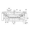
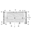
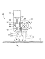
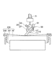
図1は第1の実施形態に係るスキージ研磨装置を示す正面図、図2は図1のスキージ研磨装置の平面図、図3は図1のスキージ研磨装置のスキージ角度調節機構の側面図である。
[First Embodiment]
1 is a front view showing a squeegee polishing apparatus according to the first embodiment, FIG. 2 is a plan view of the squeegee polishing apparatus of FIG. 1, and FIG. 3 is a side view of a squeegee angle adjusting mechanism of the squeegee polishing apparatus of FIG. .
図3に示すように、スキージ11は、例えばゴム或いはゴムに類似した弾力性を有する材質からなり、該スキージ11を保持する例えば金属製のスキージホルダ12とともにスキージユニット10を構成している。
As shown in FIG. 3, the
このうちスキージ11は、図1における左右方向に長尺な板状に構成されている。スキージホルダ12は、スキージ11を、その表裏面を長手方向に亘って挟持することにより保持している。
Among these, the
図1に示すように、第1の実施形態に係るスキージ研磨装置は、スキージ11を研磨する研磨動作の際にスキージユニット10をクランプするクランプ機構20と、該クランプ機構20によりクランプされた状態のスキージユニット10のスキージ11を研磨する研磨材(研磨手段)31を備える研磨部30と、研磨材31にスキージ11を当接させた状態でスキージユニット10を該研磨材31に沿って移動させることによるスキージ11の研磨動作などを行うスキージユニット走行機構(移動機構)40と、研磨動作の際の研磨材31に対するスキージ11の接触角度を調節する角度調節機構50と、研磨動作の際の研磨材31に対するスキージ11の平行度を調節する(平行だしを行う)平行だし機構60と、研磨動作の際の研磨材31に対するスキージ11の押し付け力を調節する押付力調節機構70と、研磨動作に際しての各種の調節条件(後述)の入力操作を含む各種操作を行うための操作部(入力操作手段を含む)80(図8)と、クランプ機構20、スキージユニット走行機構40、角度調節機構50、平行だし機構60及び押付力調節機構70を統括的に制御する制御部90(図8)と、を備えて構成されている。
As illustrated in FIG. 1, the squeegee polishing apparatus according to the first embodiment includes a
このうちクランプ機構20は、図3に示すように、スキージユニット10のスキージホルダ12をクランプするクランプ部(保持部)21と、該クランプ部21に動力を付与してクランプ動作を行わせるホルダ固定用シリンダ22と、を備えて構成されている。
Among these, as shown in FIG. 3, the
クランプ部21は、ホルダ固定用シリンダ22により被動されてスキージホルダ12の表裏面をその長手方向に亘って挟持することにより、スキージユニット10を、例えば下向きに保持する。
The
研磨部30は、図1に示すように、スキージ11の端部(エッジ部)を研磨する研磨材31と、該研磨材31が上面に載置された研磨テーブル32と、を備えて構成されている。
As shown in FIG. 1, the polishing
この研磨部30は、例えば、クランプ機構20によりクランプされるスキージユニット10の下方に位置するように配され、研磨テーブル32は、その上面に研磨材31を略水平状態に支持している。
The polishing
研磨材31は、スキージ11の長手方向(図1の左右方向)における長さよりも幅が大きく設定されているとともに(図2参照)、研磨動作時のスキージ11の移動距離(図7に示す研磨ストロークS)よりも縦に長く形成されている。
The abrasive 31 is set to have a width larger than the length of the
なお、研磨材31は、スキージユニット走行機構40により移動されるスキージ11の移動面(スキージ11の先端部の移動軌跡により構成される面)に対して略平行に(例えば±50μmの平行度を保つように)配置されている。
The abrasive 31 is substantially parallel to the moving surface of the
また、研磨材31は、例えば砥石からなり、その粒度は、例えば#200〜#1000程度が好ましい。 The abrasive 31 is made of, for example, a grindstone, and the particle size is preferably about # 200 to # 1000, for example.
スキージユニット走行機構40は、図2に示すように、例えばサーボモータからなり正逆回転が可能な走行用モータ41と、この走行用モータ41の左右の駆動軸42の先端にそれぞれ連結された一対のプーリ43と、このプーリ43の各々と対をなす一対のプーリ44と、これら2組のプーリ43,44間に各々架け渡された一対のタイミングベルト45と、この一対のタイミングベルト45の回転に伴いスキージ11の走行方向(図2の矢印A及びB方向で、且つ、研磨材31の面方向に沿う方向)に走行する走行バー46と、この走行バー46をスキージ11の走行方向にガイドする一対のLMガイド47と、を備えて構成されている。
As shown in FIG. 2, the squeegee
このうち一対のLMガイド47は、走行方向に長尺に構成され、各々の長手方向が走行方向に沿うように、研磨材31の左右両脇にそれぞれ配置されている。また、プーリ43、44は、LMガイド47の両端位置に配置され、走行バー46は研磨材31の上方に配置されている。
Among these, the pair of LM guides 47 are configured to be long in the traveling direction, and are respectively disposed on the left and right sides of the abrasive 31 so that each longitudinal direction is along the traveling direction. Further, the
このようなスキージユニット走行機構40においては、走行用モータ41の駆動に連動してプーリ43が回動するのに伴い、タイミングベルト45がプーリ43,44間に架け渡された状態でプーリ44を伴って回動し、該タイミングベルト45の回動に伴い走行バー46が研磨材31の上方においてLMガイド47によりガイドされて走行方向に直線移動する。
In such a squeegee
ここで、走行バー46には、平行だし機構60、角度調節機構50及びクランプ機構20が一体に設けられている。このため、クランプ機構20のクランプ部21にクランプされた状態のスキージユニット10も、走行バー46の移動に伴い走行方向に直線移動する。
Here, the traveling
なお、走行用モータ41の回転方向に応じて、矢印A方向又はB方向の何れかの走行方向にクランプ部21及びスキージユニット10を移動させることができる(走行用モータ41の回転方向を制御することにより走行方向を選択することができる)。
Note that the
また、スキージユニット走行機構40によるスキージ11の移動可能領域は、研磨材31の研磨面のほぼ全域、並びに、該研磨材31の脇に配置された平行だしセンサ68(後述)の位置(図2の平行だし位置H)を含む領域とされている。
Further, the movable area of the
角度調節機構50は、図3に示すように、例えばパルスモータからなり正逆回転可能な角度制御モータ(回転駆動手段)51と、この角度制御モータ51により軸周りに回転駆動されるボールネジ52と、このボールネジ52に対し外挿状態で螺合した移動部53と、この移動部53と一体的に設けられたラックギア(ラック)54と、このラックギア54に対して噛合しているとともにクランプ機構20のクランプ部21と一体的に設けられたピニオンギア(ピニオン)55と、移動部53と一体的に設けられた被検出部としてのスキージ角度調整用ドグ56と、このスキージ角度調整用ドグ56の上限位置を検出することにより角度原点を検出する角度原点センサ57と、スキージ角度調整用ドグ56の下限位置を検出することにより移動部53のオーバーランを未然に検出するオーバーランセンサ58と、ラックギア54を直線移動方向にガイドするラックLMベース59と、クランプ部21を該クランプ部21の長手方向周りに回動可能に支持する支持部5(図1)と、を備えて構成されている。
As shown in FIG. 3, the
なお、以上において、角度制御モータ51、ボールネジ52、移動部53、ラックギア54、ピニオンギア55及びラックLMベース59により、クランプ部21に回動力を付与する回動力付与部が構成されている。
In the above description, the
なお、このような構成の角度調節機構50は、例えば、クランプ部21の左右両端部に位置してそれぞれ設けられている。つまり、スキージ研磨装置は、スキージ11の(研磨材31側の端部の)長手方向において相互に離間した一対の角度調節機構50を備えている。
In addition, the
このような角度調節機構50においては、角度制御モータ51によりボールネジ52を回転駆動させることにより、移動部53がボールネジ52の軸方向に沿って上又は下に直線移動する。この直線移動に伴いラックギア54も上又は下に直線移動する。このラックギア54の移動に伴いピニオンギア55は図3の矢印C方向又はD方向に回動する。すると、このピニオンギア55と一体的とされているとともに支持部5により回動可能に支持されているクランプ部21は、矢印E方向又はF方向に回動する。従って、クランプ部21により保持されているスキージユニット10も、矢印E方向又はF方向に回動する。
In such an
なお、スキージユニット10の回転方向(矢印E、F方向)は、スキージ11の端部の長手方向に対して直交する面に含まれる方向である。つまり、本実施形態の場合、後述する平行だしを行った状態では、スキージユニット10の回転方向は、略鉛直面に含まれる方向となる。
Note that the rotation direction of the squeegee unit 10 (the direction of arrows E and F) is a direction included in a plane orthogonal to the longitudinal direction of the end of the
ここで、移動部53及びラックギア54の直線移動量、並びに、ピニオンギア55、クランプ部21及びスキージユニット10の回転移動量(回転角度)は、それぞれ角度制御モータ51の駆動パルス数に依存する。
Here, the linear movement amounts of the moving
また、移動部53及びラックギア54の移動方向、並びに、ピニオンギア55、クランプ部21及びスキージユニット10の回転方向は、それぞれ角度制御モータ51の回転方向に依存する。
Further, the moving direction of the moving
つまり、角度制御モータ51を、その回転方向及び駆動パルス数を適宜に制御して駆動させることにより、クランプ部21にクランプされた状態のスキージ11の研磨材31に対する角度を上記回転方向(矢印E、F方向)において調節することが可能となっている。
That is, the
なお、一対の角度調節機構50は、相互に独立して調節動作が可能となっている。つまり、各々の角度制御モータ51の駆動パルス数を独立に制御可能となっている。そして、これら一対の角度調節機構50の協働によりスキージ角度を調節するので、高精度に、研磨動作の際における研磨材31の研磨面に対するスキージ11のスキージ角度(接触角度)を調節することができる。
The pair of
ここで、研磨動作の際のスキージ角度(スキージ角度θ1)を図示すると図3のようになる。 Here, the squeegee angle (squeegee angle θ 1 ) during the polishing operation is shown in FIG.
なお、スキージ角度は、クランプ部21の回転位相が同一条件であってもスキージ11を挟持するスキージホルダ12の形状に応じて変化することと、研磨材31に対する最適なスキージ角度は印刷条件によって異なることから、クランプ部21の角度(矢印E、F方向における角度)は、例えば0度〜90度までの範囲で調節可能となっていることが好ましい。
Note that the squeegee angle varies depending on the shape of the
次に、平行だし機構60は、スキージ11の研磨材31側の端部と研磨材31の研磨面との平行度を調節するものである。
Next, the
この平行だし機構60は、例えば、図1に示すようにクランプ部21の左右両端部にそれぞれ位置して設けられ、クランプ部21の両端部の高さ(鉛直位置)をそれぞれ調節する一対の高さ調節機構(距離調節機構)6と、図2に示すようにスキージ11の走行方向(矢印A、B方向)において研磨材31と隣接する位置に、クランプ部21の長手方向において相互に離間した位置に配置された一対の平行だしセンサ(位置検出センサ)68と、を備えて構成されている。
For example, as shown in FIG. 1, the
つまり、平行だし機構60は、高さ調節機構6及び平行だしセンサ68を、スキージ11の(研磨材31側の端部の)長手方向において相互に離間してそれぞれ一対ずつ備えている。
That is, the
このうち高さ調節機構6は、図5に示すように、例えばパルスモータからなる平行だしモータ61と、この平行だしモータ61により軸周りに回転駆動されるボールネジ62と、このボールネジ62の回動に伴い上下動する移動部63と、この移動部63に一体的に設けられた被検出部としての平行だし用ドグ64と、この平行だし用ドグ64の上限位置を検出することにより高さ原点を検出する高さ原点センサ65と、平行だし用ドグ64の下限位置を検出することにより移動部63のオーバーランを未然に検出するオーバーランセンサ66と、移動部63を直線移動方向にガイドするLMガイド67と、を備えて構成されている。
Among them, the
また、2個の平行だしセンサ68の光軸68aは、それぞれ研磨材31の研磨面の高さと同一になるように予め調整されている。
The
このような平行だし機構60においては、平行だしモータ61によりボールネジ62を回転駆動させることにより、移動部63がボールネジ62の軸方向に沿って上又は下に直線移動する。
In such a
ここで、各平行だし機構60の移動部63には、それぞれ、角度調節機構50及びクランプ部21の一端ずつが一体に設けられている。
Here, one end of each of the
このため、一方の平行だし機構60の移動部63の移動に伴い、クランプ部21にクランプされた状態のスキージユニット10の一端側が上又は下に移動し、同様に、他方の平行だし機構60の移動部63の移動に伴い、クランプ部21にクランプされた状態のスキージユニット10の他端側が上又は下に移動する。
For this reason, with the movement of the moving
ここで、移動部63並びに該移動部63に伴う角度調節機構50及びクランプ部21の移動量は、平行だしモータ61の駆動パルス数に依存する。
Here, the moving amount of the moving
また、移動部63、角度調節機構50及びクランプ部21の移動方向は、平行だしモータ61の駆動パルス数に依存する。
Further, the moving direction of the moving
更に、一対の高さ調節機構6は、相互に独立して高さ調節動作が可能となっている。つまり、各々の平行だしモータ61の駆動パルス数を独立に制御可能となっている。
Further, the pair of
従って、各平行だしモータ61の駆動パルス数及び回転方向を適宜に調節することにより、すなわち、各高さ調節機構6の協働により、クランプ部21にクランプされた状態のスキージ11の研磨材31側の端部の研磨面に対する平行度を調節することができる。
Accordingly, the abrasive 31 of the
具体的には、例えば、スキージ11を一端上昇させた後で、スキージ11の端部が一対の平行だしセンサ68によりそれぞれ検出される位置まで該スキージ11を一対の高さ調節機構6によりそれぞれ下降量を制御して下降させることにより、スキージ11の平行度を調節することができる。
Specifically, for example, after the
また、押付力調節機構70は、スキージユニット10を、スキージ11を研磨材31の研磨面に対して押し付けるように付勢するとともに、その押し付け力が可変に構成されたスキージ昇降用シリンダ71と、平行だし機構60の一対の高さ調節機構6間に架け渡された動力伝達バー72(図1)と、を備えて構成されている。
In addition, the pressing
スキージ昇降用シリンダ71は、動力伝達バー72を介して一対の高さ調節機構6を昇降動作させ、該高さ調節機構6とともに、角度調節機構50、クランプ機構20及びスキージユニット10を昇降動作させる。
The
そして、スキージ昇降用シリンダ71によるスキージユニット10の下降量を調節することにより、スキージ11を研磨材31の研磨面に対して押し付ける押し付け力を調節することが可能となっている。
Then, by adjusting the descending amount of the
次に、操作部80(図8)は、研磨動作に際しての各種の調節条件として、例えば、スキージ角度、スキージ11を研磨材31の研磨面に対して押し付ける押し付け力、押し込み量(後述)、スキージ11の移動速度、研磨動作回数などの入力操作が可能となっている他に、研磨動作の開始操作やクランプ動作の指示操作などが可能に構成されている。
Next, the operation unit 80 (FIG. 8) includes, as various adjustment conditions during the polishing operation, for example, a squeegee angle, a pressing force that presses the
制御部90には、図8に示すように、操作部80からの操作検出信号、各角度調節機構50の角度原点センサ57、オーバーランセンサ58、平行だし機構60の各高さ調節機構6の高さ原点センサ65、オーバーランセンサ66、平行だし機構60の各平行だしセンサ68からの各検出信号が入力されるようになっている。
As shown in FIG. 8, the
制御部90は、これらの各入力信号に基づき、クランプ機構20のホルダ固定用シリンダ22、スキージユニット走行機構40の走行用モータ41、各角度調節機構50の角度制御モータ51、平行だし機構60の各高さ調節機構6の平行だしモータ61、押付力調節機構70のスキージ昇降用シリンダ71の動作制御を行う。
Based on these input signals, the
なお、制御部90は、例えば、CPU、ROM、RAMなどを備えて構成され、このうちCPUは制御動作を実行し、ROMにはCPUの制御プログラムなどが記憶され、RAMはCPUの作業領域などとして機能する。
The
次に、以上のように構成されたスキージ研磨装置の動作を説明する。 Next, the operation of the squeegee polishing apparatus configured as described above will be described.
スキージ11の研磨を行うには、先ず、図3に示すように、スキージユニット10のスキージホルダ12をクランプ機構20のクランプ部21によりクランプして保持させる。
In order to polish the
その後の調整動作は、例えば以下の要領で、制御部90の制御下で自動的に行われる。
The subsequent adjustment operation is automatically performed under the control of the
なお、所望のスキージ角度θ1、押し付け力、押し込み量(後述)、研磨動作の際のスキージ11の移動速度、研磨動作回数などの研磨条件は予め操作部80を操作することにより入力されているものとする。
Polishing conditions such as a desired squeegee angle θ 1 , pressing force, pressing amount (described later), moving speed of the
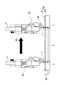
先ず、スキージ角度θ1を調節するために、角度制御モータ51によりスキージユニット10が図3の矢印E方向に回転され(図4(a))、角度原点センサ57がスキージ角度調整用ドグ56を検出した位置で角度制御モータ51が停止する(図4(b))。
First, in order to adjust the squeegee angle θ 1 , the
このときのスキージの角度を原点角度θ0とし、角度制御モータ51の駆動パルス数のカウント数をリセットする。
The angle of the squeegee at this time is set to the origin angle θ 0, and the count number of the drive pulses of the
この位置から任意の所望のスキージ角度θ1に移動する為の移動角度をθ2とすると、θ2は以下の式で求められる。 If the moving angle for moving from this position to any desired squeegee angle θ 1 is θ 2 , θ 2 can be obtained by the following equation.
θ2=θ1−θ0
原点角度θ0は設計値により決定される固定値であり、スキージ角度θ1も、予め操作部80の操作により入力されている。制御部90は、上記の式を用いて求めた移動角度θ2を角度制御モータ51の駆動パルス数に換算し、該換算したパルス数だけ角度制御モータ51を駆動させてクランプ部21を図3の矢印F方向に回転させる。
θ 2 = θ 1 −θ 0
The origin angle θ 0 is a fixed value determined by a design value, and the squeegee angle θ 1 is also input in advance by operating the operation unit 80. The
これにより、スキージユニット10のスキージ11を所望のスキージ角度θ1、すなわち印刷動作の際におけるスクリーンに対する接触角度と同一のスキージ角度θ1に調節することができる。
As a result, the
次に、スキージ11の平行度を調節するために、スキージユニット走行機構40がスキージ11を平行だし位置H(図2:平行だしセンサ68の上部)に移動させる。
Next, in order to adjust the parallelism of the
続いて、平行だしモータ61がスキージ11を上昇させる(図6(a))。平行だしモータ61は、高さ原点センサ65が平行だし用ドグ64を検出したところで停止する(図6(b))。
Subsequently, the paralleling
その状態で、スキージ昇降用シリンダ71が、各高さ調節機構6とともに各角度調節機構50、クランプ機構20及びスキージユニット10を下降させる(図6(b)→図6(c))。
In this state, the
続いて、各高さ調節機構6の各平行だしモータ61がスキージ11を下降させる(図6(c)→図6(d))。各平行だしモータ61は、一対の平行だしセンサ68がそれぞれスキージ11の端部を検出したところで停止する(図6(d))。これにより、スキージ11の研磨材31側の端部と研磨材31の研磨面とが平行になる。このとき、各平行だしモータ61のパルス数のカウント数をリセットする。
Subsequently, each paralleling
この後、スキージ昇降用シリンダ71が、各高さ調節機構6とともに各角度調節機構50、クランプ機構20及びスキージユニット10を図6(a)及び(b)の位置まで上昇させる。
Thereafter, the
ここで、実際の印刷では、印刷面に対するスキージ11の押し込み量を調節している。押し込み量とは、スキージ11から印刷面に対して予め定められた印刷圧力(印圧)が加わるような、印刷面からのスキージ11の下降量のことである。
Here, in actual printing, the pushing amount of the
そこで、制御部90は、予め操作部80の操作により入力された押し込み量を平行だしモータ61のパルス数に換算し、左右の平行だしモータ61によって、押し込み量と同一量だけスキージ11を下降させる。
Therefore, the
これにより、スキージ11と研磨面との平行度を維持したまま、該研磨面に対するスキージ11の押し込み量を設定することができる。
Thereby, the pushing amount of the
以上により、スキージ11の角度調節(スキージ角度θ1の調節)、平行度の調節及び押し込み量の調節が完了し、これらのパラメータをそれぞれ印刷時と略同一の値に設定することができる。 As described above, the adjustment of the angle of the squeegee 11 (adjustment of the squeegee angle θ 1 ), the adjustment of the parallelism, and the adjustment of the push-in amount are completed, and these parameters can be set to substantially the same values as in printing.
続いて、スキージ11のエッジ部の研磨動作について、図7を参照して説明する。
Next, the polishing operation of the edge portion of the
先ず、走行用モータ41によりスキージ11を研磨材31の上方における研磨開始位置Kに移動させた後、スキージ昇降用シリンダ71によりスキージ11を下降させ、スキージ11のエッジ部を研磨材31の上面に接触させる。
First, after the
ここで、スキージ昇降用シリンダ71は、スキージ11から研磨材31に加わる押し付け力が、予め操作部80の操作により入力された押し付け力となるように、電空比例弁を介して出力を調節する。
Here, the
ここで、この押し付け力は、実際の印刷動作の際におけるスクリーン版に対するスキージ11の印刷圧力(印圧)と略同一の押し付け力に設定することが好ましい。押し付け力を実際の印刷動作の際の印圧と同一の力に設定することにより、スキージ角度、押し込み量の設定値と合わせてスキージ11の変形を印刷動作の際におけるのと同様の状態にすることができる。
Here, the pressing force is preferably set to a pressing force substantially the same as the printing pressure (printing pressure) of the
このようにスキージ11を研磨材31に押し付けた状態で、走行用モータ41によりスキージ11を研磨終了位置Lに移動させる。つまり、スキージ11を研磨面に当接させた状態で該研磨面に沿って直線移動させることにより研磨動作を行う。
With the
ここで、走行用モータ41は、スキージ11の移動速度が、操作部80の操作により予め入力された移動速度となるように制御される。つまり、ここで、制御部90及びスキージユニット走行機構40は、研磨動作の際の研磨面に対するスキージ11の相対移動速度を調節する移動速度調節手段として機能する。
Here, the traveling
なお、スキージ11の移動速度は、より実際の印刷の状態を再現できるように、例えば、10mm/sec〜200mm/secの範囲で適宜に調節できるようになっていることが好ましい。
In addition, it is preferable that the moving speed of the
研磨終了位置Lにスキージ11が移動したところで、スキージ11はスキージ昇降用シリンダ71により上昇され、再び走行用モータ41により研磨開始位置Kに戻される。
When the
この動作を、操作部80の操作により予め指定された研磨動作回数だけ繰り返すことにより、スキージ11のエッジの研磨が行われる。
By repeating this operation as many times as the number of polishing operations specified in advance by operating the operation unit 80, the edge of the
なお、研磨動作回数は、例えば、スキージ11のエッジ部の研磨状態が安定する10回〜20回程度の範囲内とすることが好ましい。
The number of polishing operations is preferably in the range of about 10 to 20 times where the polishing state of the edge portion of the
以上のような第1の実施形態によれば、研磨動作の際における研磨材31の研磨面に対するスキージ11の接触角度(スキージ角度θ1)を調節するための角度調節機構50を備えるので、作業者の手作業の調整に頼ることなく、自動的且つ高精度に、スキージ11を所望の接触角度、すなわち、例えば実際の印刷動作の際におけるスクリーンに対する接触角度と略同一の接触角度に調節した状態で、研磨動作を行うことができる。
According to the first embodiment as described above, the
よって、印刷スジの重要な発生要因となるスキージ11のエッジ部のバリ、欠けを除去する研磨を高精度に行うことが可能となる。しかも、スキージホルダ12の形状やスキージの11厚さなどに関わらず、接触角度を調節することができる。加えて、スキージ11の材料や印刷条件に応じて適宜にスキージ11の接触角度を調節して研磨を行うこともできる。
Therefore, it is possible to perform polishing with high accuracy to remove burrs and chips on the edge portion of the
また、一対の角度調節機構50を備え、該一対の角度調節機構50は、スキージ11の研磨材31の端部の長手方向において相互に離間して配置されているので、より正確にスキージ11の接触角度を調節することができる。
Further, a pair of
加えて、一対の角度調節機構50は、相互に独立に動作し、協働によりスキージ11の角度を調節するので、より高精度にスキージ11の接触角度を調節することができる。
In addition, the pair of
また、スキージ11の研磨材31側の端部の長手方向を研磨面に対して平行状態に調節する平行だし機構60を備えるので、スキージホルダ12に対するスキージ11の取り付け状態のバラツキや、スキージホルダ12のスキージ研磨装置のクランプ部21への取り付け状態のバラツキや、スキージ11の形状或いは長さに関わらず、研磨面に対するスキージ11の平行度を良好な状態にして研磨動作を行うことができる。よって、スキージ11の長手方向における研削量を均一にすることができ、研磨の仕上がり状態をスキージ11の長手方向において均一にすることができる。
In addition, since the parallel squeezing
この平行だし機構60は、スキージ11の端部と研磨面との距離を調節する距離調節機構6を、スキージ11の長手方向において相互に離間して一対備えて構成されているので、より高精度にスキージ11の平行度を調節することができる。
The
更に、スキージ11を研磨面に対して押し付けるように付勢するとともに、その押し付け力を可変に構成された押付力調節機構70を備えるので、スキージ11を所望の押し付け力、すなわち、例えば実際の印刷動作の際におけるスクリーン版に対する押し付け力(印圧)と略同一の押し付け力で研磨面に対して押し付けることができ、その状態で研磨動作を行うことができる。つまり、例えば実際の印刷動作時と同様のスキージ11のたわみを再現した状態で研磨動作を行うことができるので、スキージ11において実際の印刷動作時にスクリーンに接触する部分(面)を研磨することができる。
Further, the
また、スキージユニット走行機構40は、スキージ11を実際の印刷動作の際におけるスクリーン版に対する相対移動方向と同一方向に移動させて研磨動作を行うので、より高精度に、スキージ11において実際の印刷動作時にスクリーンに接触する部分(面)を研磨することができる。
Further, since the squeegee
加えて、スキージユニット走行機構40は、スキージ11を実際の印刷動作の際におけるスクリーン版に対する相対移動速度と同一の移動速度で研磨動作を行うので、より高精度に、スキージ11において実際の印刷動作時にスクリーンに接触する部分(面)を研磨することができる。
In addition, since the squeegee
以上要するに、本実施形態によれば、スキージ11の接触角度、平行度、押し付け力、移動速度を実際の印刷動作時におけるスクリーン版に対する接触角度、平行度、押し付け力(印圧)、移動速度と略同一条件に調節したり、スキージ11やスキージホルダ12の形状・材質に関わらず最適な接触角度、平行度、押し付け力に調節することができ、スキージ11のエッジ部を理想的な状態に研磨することができる。
In short, according to the present embodiment, the contact angle, parallelism, pressing force, and moving speed of the
よって、印刷時と研磨時との条件の違い(スキージ11のたわみ、接触角度など)によって生じる印刷すじ発生を防止することができ、印刷スジ不良発生やスキージ交換による生産ロスを防止することができる。
Therefore, it is possible to prevent the occurrence of printing streaks caused by the difference in conditions between printing and polishing (bending of
なお、上記の実施形態では、スキージ角度θ1、押し付け力、押し込み量といった各パラメータを印刷時と同一の値に設定する例を説明したが、本発明はこれに限らず、必要に応じて各パラメータを補正して入力しても良い。 In the above-described embodiment, the example in which the parameters such as the squeegee angle θ 1 , the pressing force, and the pressing amount are set to the same values as in the printing has been described, but the present invention is not limited thereto, and each parameter is set as necessary. The parameter may be corrected and input.
また、上記の実施形態では、一対の角度調節機構50を備える例を説明したが、角度調節機構は1つだけであっても良い。
In the above embodiment, an example in which the pair of
〔第2の実施形態〕
上記の第1の実施形態では、研磨材が砥石からなる研磨材31である例を説明したが、本発明はこれに限らず、例えば、研磨材をメッシュにすることも可能である。
[Second Embodiment]
In the first embodiment, the example in which the abrasive is the abrasive 31 made of a grindstone has been described. However, the present invention is not limited to this, and for example, the abrasive can be a mesh.
そこで、第2の実施形態では、研磨材としてメッシュを用いる例について説明する。 Therefore, in the second embodiment, an example in which a mesh is used as an abrasive will be described.
図9は第2の実施形態に係るスキージ研磨装置の側面図である。 FIG. 9 is a side view of a squeegee polishing apparatus according to the second embodiment.
なお、第2の実施形態に係るスキージ研磨装置は、その研磨部230のみが上記の第1の実施形態に係るスキージ装置における研磨部30と異なり、その他の点では第1の実施形態に係るスキージ装置と同様に構成されている。そのため、以下では第1の実施形態に係るスキージ装置におけるのと同様の構成要素には同一の符号を付して、その説明を省略する。
Note that the squeegee polishing apparatus according to the second embodiment is different from the polishing
第2の実施形態に係るスキージ装置は、図9に示すように、第1の実施形態における研磨部30に代えて研磨部230を備えている。
As shown in FIG. 9, the squeegee device according to the second embodiment includes a
この研磨部230は、研磨テーブル32と、メッシュからなり研磨テーブル32上に配置された研磨材231と、研磨材231を研磨テーブル32に固定する固定治具232と、を備えて構成されている。
The polishing
研磨材231は、例えばテトロンメッシュまたはステンレスメッシュであり、固定治具232により研磨テーブル32に対し一定の距離(例えば5mm〜10mm程度)と一定のテンションを保つように固定されている。
The abrasive 231 is, for example, a tetron mesh or a stainless mesh, and is fixed to the polishing table 32 by a fixing
このような研磨部230は、上記の第1の実施形態における研磨部30と同様に、クランプ機構20によりクランプされるスキージユニット10の下方に位置するように配されている。
Such a
また、研磨テーブル32は、スキージユニット走行機構40により移動されるスキージ11の移動面(スキージ11の先端部の移動軌跡により構成される面)に対して略平行に(例えば±50μmの平行度を保つように)配置されている。
Further, the polishing table 32 is substantially parallel to the moving surface of the
また、研磨材231は、上記の第1の実施形態における研磨材31と同様の寸法面積に設定されている。 The abrasive 231 is set to have the same dimensional area as the abrasive 31 in the first embodiment.
研磨材231がメッシュである方式の利点は、スキージ11からの加圧により研磨材231が押されて研磨テーブル32の上面の形状(つまり平面)に倣う為、研磨材231の面の位置を高精度に調節する必要がなく、また、研磨の際に生じるスキージ11の研磨屑の大半が研磨材231上に残る為、研磨材231の交換と研磨テーブル32上面の簡単な清掃により、容易に装置の清掃を行うことができる点である。
The advantage of the method in which the abrasive 231 is a mesh is that the abrasive 231 is pushed by the pressure from the
以上のような第2の実施形態によれば、上記の第1の実施形態におけるのと同様の効果が得られる他に、スキージ研磨装置の清掃が容易になるという利点が得られる。 According to the second embodiment as described above, in addition to the same effects as those in the first embodiment described above, there is an advantage that the squeegee polishing apparatus can be easily cleaned.
なお、上記の第2の実施形態では、メッシュからなる研磨材231を固定治具232により研磨テーブル32に対し一定の距離と一定のテンションを保つように固定した状態で研磨を行う例について説明したが、該研磨材231に代えて(可撓性の)シート状の砥石を用いても同様の効果が得られる。
In the second embodiment, the example in which polishing is performed in a state where the abrasive 231 made of mesh is fixed to the polishing table 32 with a fixed
10 スキージユニット
11 スキージ
12 スキージホルダ
20 クランプ機構
21 クランプ部(保持部)
22 ホルダ固定用シリンダ
30 研磨部
31 研磨材(研磨手段)
32 研磨テーブル
40 スキージユニット走行機構(移動機構、移動速度調節手段)
41 走行用モータ
50 角度調節機構
5 支持部
51 角度制御モータ(回転駆動手段、回動力付与部)
52 ボールネジ(回動力付与部)
53 移動部(回動力付与部)
54 ラックギア(ラック、回動力付与部)
55 ピニオンギア(ピニオン、回動力付与部)
59 ラックLMベース(回動力付与部)
60 平行だし機構
6 高さ調節機構(距離調節機構)
61 平行だしモータ
62 ボールネジ
63 移動部
68 平行だしセンサ(位置検出センサ)
70 押付力調節機構(押付機構)
71 スキージ昇降用シリンダ
80 操作部(入力操作手段)
90 制御部(移動速度調節手段)
230 研磨部
231 研磨材(研磨手段)
DESCRIPTION OF
22
32 Polishing table 40 Squeegee unit travel mechanism (moving mechanism, moving speed adjusting means)
41
52 Ball screw (rotating power application part)
53 Moving part (rotating power applying part)
54 Rack gear (rack, rotating power application part)
55 Pinion gear (pinion, rotating power application part)
59 rack LM base (rotation power application part)
60
61
70 Pressing force adjustment mechanism (pressing mechanism)
71 Squeegee lifting / lowering cylinder 80 Operation section (input operation means)
90 control unit (moving speed adjusting means)
230
Claims (18)
前記スキージを研磨する研磨手段と、
研磨動作の際における前記研磨手段の研磨面に対する前記スキージの接触角度を調節する角度調節機構と、
を備えることを特徴とするスキージ研磨装置。 In a squeegee polishing apparatus for polishing screen printing squeegees,
Polishing means for polishing the squeegee;
An angle adjusting mechanism for adjusting a contact angle of the squeegee with respect to a polishing surface of the polishing means during a polishing operation;
A squeegee polishing apparatus comprising:
前記角度調節機構は、前記保持部の角度を調節することにより、該保持部に保持されたスキージの前記研磨面に対する接触角度を調節することを特徴とする請求項1に記載のスキージ研磨装置。 A holding portion for holding the squeegee during a polishing operation;
2. The squeegee polishing apparatus according to claim 1, wherein the angle adjusting mechanism adjusts a contact angle of the squeegee held by the holding unit with respect to the polishing surface by adjusting an angle of the holding unit.
前記保持部を回動可能に支持する支持部と、
前記保持部に回動力を付与する回動力付与部と、
を備えて構成され、
前記回動力付与部により前記保持部の回転角度を調節することによって、該保持部に保持されたスキージの前記研磨面に対する接触角度を調節することを特徴とする請求項2に記載のスキージ研磨装置。 The angle adjustment mechanism includes:
A support portion that rotatably supports the holding portion;
A turning force applying portion that applies turning force to the holding portion;
Configured with
3. The squeegee polishing apparatus according to claim 2, wherein a contact angle of the squeegee held by the holding unit with respect to the polishing surface is adjusted by adjusting a rotation angle of the holding unit by the turning force applying unit. .
進退移動するラックと、前記保持部と一体的に構成されて前記ラックの進退移動に伴い回動されるピニオンと、を備えて構成され、前記ピニオンの回動に伴い前記保持部に回動力が付与されることを特徴とする請求項3に記載のスキージ研磨装置。 The turning power application unit is
A rack that moves forward and backward, and a pinion that is configured integrally with the holding portion and that rotates as the rack moves forward and backward, and the rotational force is applied to the holding portion as the pinion rotates. The squeegee polishing apparatus according to claim 3, wherein the squeegee polishing apparatus is provided.
回転駆動されるボールネジと、該ボールネジの回転駆動により前記ラックを伴って進退移動される移動部と、を備えて構成されていることを特徴とする請求項4に記載のスキージ研磨装置。 The turning power application unit is
5. The squeegee polishing apparatus according to claim 4, comprising: a ball screw that is rotationally driven; and a moving unit that is moved forward and backward with the rack by the rotational driving of the ball screw.
前記ボールネジを回転駆動させる回転駆動手段を備えて構成されていることを特徴とする請求項5に記載のスキージ研磨装置。 The turning power application unit is
The squeegee polishing apparatus according to claim 5, further comprising a rotation driving unit that rotationally drives the ball screw.
前記スキージの端部と前記研磨面との距離を調節する距離調節機構を、前記スキージの前記研磨手段側の端部の長手方向において相互に離間して一対備えて構成されていることを特徴とする請求項9に記載のスキージ研磨装置。 The parallel running mechanism is
A distance adjusting mechanism for adjusting the distance between the end of the squeegee and the polishing surface is provided with a pair spaced apart from each other in the longitudinal direction of the end on the polishing means side of the squeegee. The squeegee polishing apparatus according to claim 9.
一対の前記距離調節機構は、それぞれ一対の前記位置検出センサにより前記スキージの端部が検出される位置に前記スキージを移動させることによって、前記スキージの端部を前記研磨面に対して平行状態に調節することを特徴とする請求項10に記載のスキージ研磨装置。 The parallel running mechanism includes a pair of position detection sensors for detecting the position of the end of the squeegee, spaced apart from each other in the longitudinal direction of the squeegee,
The pair of distance adjusting mechanisms move the squeegee end to a position parallel to the polishing surface by moving the squeegee to a position where the pair of position detection sensors detect the end of the squeegee. The squeegee polishing apparatus according to claim 10, wherein the squeegee polishing apparatus is adjusted.
前記角度調節機構は、入力された設定値となるように前記スキージの角度を調節することを特徴とする請求項1乃至17のいずれか一項に記載のスキージ研磨装置。
An input operation means for performing an input operation of a set value of the angle of the squeegee;
The squeegee polishing apparatus according to any one of claims 1 to 17, wherein the angle adjustment mechanism adjusts an angle of the squeegee so as to be an input set value.
Priority Applications (1)
| Application Number | Priority Date | Filing Date | Title |
|---|---|---|---|
| JP2004155847A JP2005335002A (en) | 2004-05-26 | 2004-05-26 | Squeegee polishing device |
Applications Claiming Priority (1)
| Application Number | Priority Date | Filing Date | Title |
|---|---|---|---|
| JP2004155847A JP2005335002A (en) | 2004-05-26 | 2004-05-26 | Squeegee polishing device |
Publications (1)
| Publication Number | Publication Date |
|---|---|
| JP2005335002A true JP2005335002A (en) | 2005-12-08 |
Family
ID=35489101
Family Applications (1)
| Application Number | Title | Priority Date | Filing Date |
|---|---|---|---|
| JP2004155847A Pending JP2005335002A (en) | 2004-05-26 | 2004-05-26 | Squeegee polishing device |
Country Status (1)
| Country | Link |
|---|---|
| JP (1) | JP2005335002A (en) |
Cited By (11)
| Publication number | Priority date | Publication date | Assignee | Title |
|---|---|---|---|---|
| JP2007237383A (en) * | 2006-03-13 | 2007-09-20 | Dainippon Printing Co Ltd | Doctor blade polishing apparatus and doctor blade polishing method |
| CN102744661A (en) * | 2012-07-05 | 2012-10-24 | 江苏华灿电讯股份有限公司 | Power splitter deburring device |
| JP2015227010A (en) * | 2014-05-30 | 2015-12-17 | 株式会社セリアエンジニアリング | Squeegee position automatic correction mechanism and squeegee position automatic correction method for screen printing machine |
| CN108380455A (en) * | 2018-02-26 | 2018-08-10 | 京东方科技集团股份有限公司 | Scraper device, coating system and its control method |
| CN108749291A (en) * | 2018-07-03 | 2018-11-06 | 广东北玻电子玻璃有限公司 | The scraper adjustment mechanism of screen printer |
| JPWO2017179106A1 (en) * | 2016-04-11 | 2019-02-14 | 株式会社Fuji | Solder printing machine |
| CN111941185A (en) * | 2020-09-15 | 2020-11-17 | 天津市诚捷丰智能装备制造有限公司 | Novel multifunctional bidirectional chamfering machine and use method thereof |
| CN117261163A (en) * | 2023-08-16 | 2023-12-22 | 安徽华奇管业有限公司 | Cooling and shaping device for cement pipe lining processing |
| CN118143798A (en) * | 2024-04-19 | 2024-06-07 | 江苏云景新材料有限公司 | A floor edge chamfering grinding device |
| CN118811423A (en) * | 2024-07-31 | 2024-10-22 | 昆山海汇精密制造有限公司 | Automatic feeding device for plate model cards |
| CN122033757A (en) * | 2026-04-10 | 2026-05-15 | 上海华信摩擦材料有限公司 | A grinding device for automobile brake friction pads |
-
2004
- 2004-05-26 JP JP2004155847A patent/JP2005335002A/en active Pending
Cited By (12)
| Publication number | Priority date | Publication date | Assignee | Title |
|---|---|---|---|---|
| JP2007237383A (en) * | 2006-03-13 | 2007-09-20 | Dainippon Printing Co Ltd | Doctor blade polishing apparatus and doctor blade polishing method |
| CN102744661A (en) * | 2012-07-05 | 2012-10-24 | 江苏华灿电讯股份有限公司 | Power splitter deburring device |
| CN102744661B (en) * | 2012-07-05 | 2013-08-14 | 江苏华灿电讯股份有限公司 | Power splitter deburring device |
| JP2015227010A (en) * | 2014-05-30 | 2015-12-17 | 株式会社セリアエンジニアリング | Squeegee position automatic correction mechanism and squeegee position automatic correction method for screen printing machine |
| JPWO2017179106A1 (en) * | 2016-04-11 | 2019-02-14 | 株式会社Fuji | Solder printing machine |
| CN108380455A (en) * | 2018-02-26 | 2018-08-10 | 京东方科技集团股份有限公司 | Scraper device, coating system and its control method |
| CN108749291A (en) * | 2018-07-03 | 2018-11-06 | 广东北玻电子玻璃有限公司 | The scraper adjustment mechanism of screen printer |
| CN111941185A (en) * | 2020-09-15 | 2020-11-17 | 天津市诚捷丰智能装备制造有限公司 | Novel multifunctional bidirectional chamfering machine and use method thereof |
| CN117261163A (en) * | 2023-08-16 | 2023-12-22 | 安徽华奇管业有限公司 | Cooling and shaping device for cement pipe lining processing |
| CN118143798A (en) * | 2024-04-19 | 2024-06-07 | 江苏云景新材料有限公司 | A floor edge chamfering grinding device |
| CN118811423A (en) * | 2024-07-31 | 2024-10-22 | 昆山海汇精密制造有限公司 | Automatic feeding device for plate model cards |
| CN122033757A (en) * | 2026-04-10 | 2026-05-15 | 上海华信摩擦材料有限公司 | A grinding device for automobile brake friction pads |
Similar Documents
| Publication | Publication Date | Title |
|---|---|---|
| CN111220060A (en) | Plate material quality detection equipment | |
| KR101556247B1 (en) | Squeeze blade grinding device for screen printer | |
| US9358655B2 (en) | Outer periphery polishing apparatus for disc-shaped workpiece | |
| KR101322627B1 (en) | Optical rod surface polishing device | |
| KR20170081540A (en) | Multifunctional pipe slice device | |
| KR20170032928A (en) | Apparatus for Grinding Side Edge of Thin Glass Cover | |
| KR102067982B1 (en) | Apparatus for cutting substrate | |
| CN116276127B (en) | A turning processing device and processing technology capable of eliminating the triangular edges and circles of the outer ring | |
| KR101794228B1 (en) | The Polishing method And the device of Round Edge to Mobile Phone Case for Mass Production | |
| KR100961048B1 (en) | Belt grinding apparatus | |
| JPH05337906A (en) | Continuous cutter for wood working and cutting method and device thereof | |
| TWI526278B (en) | Fiber head grinding device | |
| KR101244457B1 (en) | Apparatus for chamfering | |
| KR101467450B1 (en) | Apparatus for grinding screen print squeegee | |
| KR102067984B1 (en) | Apparatus for cutting substrate | |
| JP2579845B2 (en) | Grinding equipment for chamfering | |
| KR102158034B1 (en) | Apparatus and method for cutting substrate | |
| JP2004082241A (en) | Work supporting tool in chamfering grinding device | |
| JP2006181697A (en) | Surface polishing device and method | |
| JP2000218533A (en) | Rotating stone straightening device | |
| KR200336683Y1 (en) | Apparatus for grinding of aluminum plate in LCD | |
| TWI719417B (en) | Glue scraping apparatus | |
| KR102067985B1 (en) | Apparatus for cutting substrate | |
| JP2004338344A (en) | Gaddingly engraving machine | |
| TWM469146U (en) | Optic fiber end grinding device |
Legal Events
| Date | Code | Title | Description |
|---|---|---|---|
| RD01 | Notification of change of attorney |
Free format text: JAPANESE INTERMEDIATE CODE: A7421 Effective date: 20050906 |
|
| A521 | Written amendment |
Free format text: JAPANESE INTERMEDIATE CODE: A821 Effective date: 20050906 |