KR20160140179A - Assembly device for lower arm - Google Patents
Assembly device for lower arm Download PDFInfo
- Publication number
- KR20160140179A KR20160140179A KR1020150076469A KR20150076469A KR20160140179A KR 20160140179 A KR20160140179 A KR 20160140179A KR 1020150076469 A KR1020150076469 A KR 1020150076469A KR 20150076469 A KR20150076469 A KR 20150076469A KR 20160140179 A KR20160140179 A KR 20160140179A
- Authority
- KR
- South Korea
- Prior art keywords
- support
- lower arm
- cam bolt
- fixing
- hole
- Prior art date
Links
Images
Classifications
-
- B—PERFORMING OPERATIONS; TRANSPORTING
- B60—VEHICLES IN GENERAL
- B60G—VEHICLE SUSPENSION ARRANGEMENTS
- B60G7/00—Pivoted suspension arms; Accessories thereof
- B60G7/02—Attaching arms to sprung part of vehicle
-
- B—PERFORMING OPERATIONS; TRANSPORTING
- B62—LAND VEHICLES FOR TRAVELLING OTHERWISE THAN ON RAILS
- B62D—MOTOR VEHICLES; TRAILERS
- B62D65/00—Designing, manufacturing, e.g. assembling, facilitating disassembly, or structurally modifying motor vehicles or trailers, not otherwise provided for
- B62D65/02—Joining sub-units or components to, or positioning sub-units or components with respect to, body shell or other sub-units or components
- B62D65/12—Joining sub-units or components to, or positioning sub-units or components with respect to, body shell or other sub-units or components the sub-units or components being suspensions, brakes or wheel units
-
- B—PERFORMING OPERATIONS; TRANSPORTING
- B60—VEHICLES IN GENERAL
- B60G—VEHICLE SUSPENSION ARRANGEMENTS
- B60G2204/00—Indexing codes related to suspensions per se or to auxiliary parts
- B60G2204/40—Auxiliary suspension parts; Adjustment of suspensions
- B60G2204/42—Joints with cam surfaces
Abstract
Description
본 발명은 로워암 조립장치에 관한 것으로서, 보다 상세하게는 조립 부품수를 줄여주어 제조단가를 절감하고, 조립성을 개선하는 로워암 조립장치에 관한 것이다.BACKGROUND OF THE
일반적으로 현가장치는 차량의 승차감 및 주행 안정성을 도모하기 위한 장치로서, 차체를 차륜으로부터 안정적으로 지지하면서 차륜으로부터 제공되는 진동을 억제 및 신속히 감소시킨다.Generally, a suspension device is an apparatus for improving ride comfort and driving stability of a vehicle, which suppresses and rapidly reduces the vibration provided from the wheel while stably supporting the vehicle body from the wheel.
차륜을 차체에 연결하여 지지하도록 로워암이 사용되는바, 로워암에는 제1부쉬, 제2부쉬 및 볼조인트가 장착된다. 제1부쉬와 제2부쉬는 차체에 결합되고, 볼조인트는 차륜의 너클과 연결되어 어퍼암과 함께 차륜을 지지한다.A lower arm is used to connect and support the wheel to the vehicle body. The lower arm is equipped with a first bush, a second bush and a ball joint. The first and second bushes are coupled to the vehicle body, and the ball joint is connected to the knuckle of the wheel to support the wheel together with the upper arm.
종래에는 차량에 장착되는 멤버에 로워암의 부쉬가 조립되는데, 멤버와 로워암 간의 조립시 캠볼트의 장착이 원활하게 이루어지지 못하는 문제점이 있다. 따라서, 이를 개선할 필요성이 요청된다.Conventionally, a bush of a lower arm is assembled to a member mounted on a vehicle. However, there is a problem that the cam bolt can not be smoothly mounted when the member is assembled with the lower arm. Therefore, there is a need to improve this.
본 발명의 배경기술은 대한민국 공개특허공보 제2011-0098376호(2011.09.01 공개, 발명의 명칭 : 로워암 조립 장치)에 개시되어 있다.BACKGROUND ART [0002] The background art of the present invention is disclosed in Korean Patent Laid-Open Publication No. 2011-0098376 (published on Sep. 1, 2011, entitled Low Arm Assembly Device).
본 발명은 상기와 같은 문제점을 개선하기 위해 안출된 것으로서, 조립 부품수를 줄여주어 제조단가를 절감하고, 조립성을 개선하는 로워암 조립장치를 제공하는데 그 목적이 있다.It is an object of the present invention to provide a lower arm assembling apparatus which reduces manufacturing cost by reducing the number of assembled parts and improves assembling performance.
본 발명에 따른 로워암 조립장치는: 차체에 결합되는 멤버부; 상기 멤버부에 결합되는 고정부; 상기 멤버부에 결합되고, 상기 고정부와 마주보도록 배치되는 지지부; 및 상기 고정부와 상기 지지부 사이에 배치되는 로워암을 고정시키는 캠볼트부를 포함하고, 상기 지지부는 상기 캠볼트부의 설치위치를 유도하는 것을 특징으로 한다.A lower arm assembling apparatus according to the present invention comprises: a member coupled to a vehicle body; A fixing portion coupled to the member portion; A support portion coupled to the member portion and disposed to face the fixing portion; And a cam bolt portion for fixing a lower arm disposed between the fixed portion and the support portion, wherein the support portion guides the installation position of the cam bolt portion.
상기 지지부는: 상기 캠볼트부가 관통되는 관통홀부가 형성되고, 상기 멤버부에 양단부가 결합되는 지지몸체부; 및 상기 지지몸체부에서 돌출되고, 상기 관통홀부의 양측방향으로 각각 배치되어 상기 캠볼트부를 안내하는 지지돌출부를 포함하는 것을 특징으로 한다.Wherein the support portion includes: a support body portion having a through hole portion through which the cam bolt portion penetrates, the both end portions of the support body portion being coupled to the member portion; And a support protrusion protruding from the support body portion and disposed in both side directions of the through hole portion and guiding the cam bolt portion.
상기 지지부는: 상기 관통홀부와 상기 지지돌출부 사이에 배치되고, 상기 지지몸체부의 전면에서 함몰되어 상기 캠볼트부와 상기 지지돌출부 간의 간섭을 방지하는 지지함몰부를 더 포함하는 것을 특징으로 한다.The support portion may further include a support depression disposed between the through hole portion and the support protrusion and recessed from the front surface of the support body to prevent interference between the cam bolt portion and the support protrusion.
상기 지지함몰부는: 상기 관통홀부와 상기 지지돌출부 사이에 배치되는 함몰직선부; 및 상기 함몰직선부의 단부에서 상기 지지돌출부 방향으로 경사를 갖도록 형성되는 함몰경사부를 포함하는 것을 특징으로 한다.The support depression includes: a recessed straight portion disposed between the through hole portion and the support projection; And a depression inclined portion formed at an end of the depression rectilinear portion so as to have an inclination in the direction of the support projection.
상기 지지부는: 상기 지지몸체부의 배면 방향으로 돌출되어 상기 로워암을 안내하는 지지가이드부를 더 포함하는 것을 특징으로 한다.The support portion may further include: a support guide portion protruding toward the back surface of the support body portion and guiding the lower arm.
상기 캠볼트부는: 상기 지지돌출부 사이에 삽입되어 상기 지지몸체부에 밀착되는 고정판부; 상기 고정판부의 중심에서 치우쳐 연장되고, 상기 관통홀부를 관통하는 고정막대부; 상기 고정판부의 중심에서 치우쳐 연장되는 고정머리부; 및 상기 고정막대부에 체결되는 고정너트부를 포함하는 것을 특징으로 한다.The cam bolt portion includes: a fixing plate portion inserted between the supporting protrusions and closely contacting the supporting body portion; A fixing rod portion biased from the center of the fixing plate portion and penetrating the through hole portion; A fixed head portion biased from the center of the fixed plate portion; And a fixing nut portion fastened to the fixing bar portion.
본 발명에 따른 로워암 조립장치는 지지부가 캠볼트부의 설치위치를 유도하여 조립성을 개선할 수 있다.The lower arm assembling apparatus according to the present invention can improve the assembling performance by guiding the mounting position of the cam bolt portion.
본 발명에 따른 로워암 조립장치는 한 쌍의 지지돌출부 사이로 캠볼트부가 삽입되어 캠볼트부의 좌우 유동을 제한할 수 있다.The lower arm assembling apparatus according to the present invention can limit the lateral movement of the cam bolt portion by inserting the cam bolt portion between the pair of support protrusions.
본 발명에 따른 로워암 조립장치는 관통홀부와 지지돌출부 사이에 지지함몰부가 형성되어 캠볼트부와 지지돌출부 간의 간섭을 방지할 수 있다.The lower arm assembling apparatus according to the present invention is capable of preventing interference between the cam bolt portion and the support protrusion by forming a support depression between the through hole and the support protrusion.
본 발명에 따른 로워암 조립장치는 지지함몰부가 지지몸체부의 전면에서 함몰되도록 형성되어 지지몸체부의 강성을 보강할 수 있다.In the lower arm assembling apparatus according to the present invention, the support depression part is formed to be recessed from the front surface of the support body part to reinforce the rigidity of the support body part.
본 발명에 따른 로워암 조립장치는 지지가이드부가 로워암을 안내하여 조립성을 개선할 수 있다.The lower arm assembling device according to the present invention can improve the assembling property by guiding the lower arm to the support guide portion.
도 1은 본 발명의 일 실시예에 따른 로워암 조립장치를 개략적으로 나타내는 도면이다.
도 2는 본 발명의 일 실시예에 따른 로워암 조립장치에서 로워암이 조립된 상태를 개략적으로 나타내는 도면이다.
도 3은 본 발명의 일 실시예에 따른 로워암 조립장치에서 지지부를 개략적으로 나타내는 도면이다.
도 4는 도 2의 A-A 단면도이다.
도 5는 도 2의 B-B 단면도이다.
도 6은 본 발명의 일 실시예에 따른 로워암 조립장치에서 캠볼트부를 개략적으로 나타내는 도면이다.1 is a view schematically showing a lower arm assembling apparatus according to an embodiment of the present invention.
FIG. 2 is a view schematically showing a state in which a lower arm is assembled in a lower arm assembling apparatus according to an embodiment of the present invention. FIG.
3 is a view schematically showing a support part in a lower arm assembling apparatus according to an embodiment of the present invention.
4 is a sectional view taken along the line AA in Fig.
5 is a sectional view taken along line BB of Fig.
6 is a view schematically showing a cam bolt in a lower arm assembling apparatus according to an embodiment of the present invention.
이하, 첨부된 도면들을 참조하여 본 발명에 따른 로워암 조립장치의 실시예를 설명한다. 이러한 과정에서 도면에 도시된 선들의 두께나 구성요소의 크기 등은 설명의 명료성과 편의상 과장되게 도시되어 있을 수 있다. 또한, 후술되는 용어들은 본 발명에서의 기능을 고려하여 정의된 용어들로서, 이는 사용자, 운용자의 의도 또는 관례에 따라 달라질 수 있다. 그러므로, 이러한 용어들에 대한 정의는 본 명세서 전반에 걸친 내용을 토대로 내려져야 할 것이다.Hereinafter, an embodiment of a lower arm assembling apparatus according to the present invention will be described with reference to the accompanying drawings. In this process, the thicknesses of the lines and the sizes of the components shown in the drawings may be exaggerated for clarity and convenience of explanation. Further, terms to be described below are terms defined in consideration of functions in the present invention, which may vary depending on the intention or custom of the user, the operator. Therefore, definitions of these terms should be made based on the contents throughout this specification.
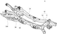
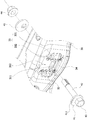
도 1은 본 발명의 일 실시예에 따른 로워암 조립장치를 개략적으로 나타내는 도면이고, 도 2는 본 발명의 일 실시예에 따른 로워암 조립장치에서 로워암이 조립된 상태를 개략적으로 나타내는 도면이다. 도 1과 도 2를 참조하면, 본 발명의 일 실시예에 따른 로워암 조립장치(1)는 멤버부(10)와, 고정부(20)와, 지지부(30)와, 캠볼트부(40)를 포함한다.FIG. 1 is a view schematically showing a lower arm assembling apparatus according to an embodiment of the present invention, and FIG. 2 is a view schematically showing a state in which a lower arm is assembled in a lower arm assembling apparatus according to an embodiment of the present invention . 1 and 2, a lower
멤버부(10)는 차체에 결합된다. 일 예로, 멤버부(10)는 멤버메인부(11)와, 멤버메인부(11)에 각각 일단부가 결합되어 마주보도록 배치되는 한 쌍의 멤버연장부(12)를 포함할 수 있다.The
고정부(20)는 멤버부(10)에 결합된다. 일 예로, 고정부(20)는 멤버연장부(12) 사이에 배치되고, 양단부가 멤버연장부(12)에 결합될 수 있다.The
지지부(30)는 멤버부(10)에 결합되고, 고정부(20)와 마주보도록 배치된다. 일 예로, 지지부(30)는 멤버연장부(12) 사이에 배치되고, 양단부가 멤버연장부(12)에 결합될 수 있다. 지지부(30)는 고정부(20)의 전방에 배치될 수 있다.The
캠볼트부(40)는 고정부(20)와 지지부(30) 사이에 배치되는 로워암(100)을 고정시킨다. 이때, 지지부(30)는 캠볼트부(40)의 설치위치를 유도한다.The
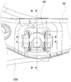
도 3은 본 발명의 일 실시예에 따른 로워암 조립장치에서 지지부를 개략적으로 나타내는 도면이고, 도 4는 도 2의 A-A 단면도이며, 도 5는 도 2의 B-B 단면도이다. 도 3 내지 도 5를 참조하면, 본 발명의 일 실시예에 따른 지지부(30)는 지지몸체부(31)와 지지돌출부(32)를 포함한다.FIG. 3 is a view schematically showing a supporting part in a lower arm assembling apparatus according to an embodiment of the present invention, FIG. 4 is a sectional view taken along the line A-A in FIG. 2, and FIG. 5 is a sectional view taken along line B-B in FIG. 3 to 5, a
지지몸체부(31)는 멤버부(10)에 양단부가 결합되고, 캠볼트부(40)가 관통되기 위한 관통홀부(311)가 형성된다. 일 예로, 지지몸체부(31)의 양단부는 멤버연장부(12)에 결합될 수 있다. 관통홀부(311)는 지지몸체부(31)의 길이방향으로 길이를 갖는 장방홀이 형성될 수 있다.The supporting
지지돌출부(32)는 지지몸체부(31)에서 돌출되고, 관통홀부(311)의 양측방향으로 각각 배치되어 캠볼트부(40)를 안내한다. 일 예로, 지지몸체부(31)의 배면에 대한 프레스 가공으로, 지지돌출부(32)가 지지몸체부(31)의 전면방향으로 돌출될 수 있다. 이때, 관통홀부(311)에 관통되는 캠볼트부(40)는 한 쌍의 지지돌출부(32) 사이에 배치될 수 있다. 지지돌출부(32)는 지지몸체부(31)에 일체로 형성되어 캠볼트부(40)를 안내하므로, 별물의 가이드물을 지지몸체부(31)에 결합하는 과정이 삭제되어 제조단가를 낮출 수 있다.The
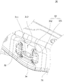
본 발명의 일 실시예에 따른 지지부(30)는 지지함몰부(33)를 더 포함할 수 있다. 지지함몰부(33)는 관통홀부(311)와 지지돌출부(32) 사이에 배치되고, 지지몸체부(31)의 전면에서 함몰되어 캠볼트부(40)와 지지돌출부(32) 간의 간섭을 방지한다. 즉, 지지몸체부(31) 자체 내구성이 저하되면, 지지돌출부(32)의 형상이 변경되어 캠볼트부(40)와 간섭될 수 있다. 그러나, 관통홀부(311)와 지지돌출부(32) 사이에 지지함몰부(33)가 배치되면, 지지돌출부(32)의 형상이 유지되어 캠볼트부(40)와의 간섭을 방지할 수 있다. 지지함몰부(33)는 지지돌출부(32)와 인접하도록 배치될 수 있다.The
지지함몰부(33)는 함몰직선부(331)와 함몰경사부(332)를 포함한다. 함몰직선부(331)는 관통홀부(311)와 지지돌출부(32) 사이에 배치된다. 일 예로, 함몰직선부(331)는 지지몸체부(31)의 상하방향으로 길이를 갖도록 형성될 수 있다. 함몰경사부(332)는 함몰직선부(331)의 단부에서 지지돌출부(32) 방향으로 경사를 갖도록 형성된다. 일 예로, 함몰경사부(332)는 함몰직선부(331)의 양단부에서 각각 연장되어 형성될 수 있다. 함몰직선부(331)는 지지몸체부(31)의 상하방향으로 작용되는 하중에 대한 강성을 증대시킬 수 있다. 함몰경사부(332)는 지지몸체부(31)의 경사 방향으로 작용되는 하중에 대한 강성을 증대시킬 수 있다.The support depression (33) includes a recessed straight portion (331) and a depression inclined portion (332). The recessed
본 발명의 일 실시예에 따른 지지부(30)는 지지가이드부(34)를 더 포함할 수 있다. 지지가이드부(34)는 지지몸체부(31)의 배면 방향으로 돌출되어 로워암(100)을 안내한다. 일 예로, 지지가이드부(34)는 지지몸체부(31)의 전면에서 함몰되고, 지지몸체부(31)의 길이방향으로 길이를 갖도록 형성될 수 있다. 지지가이드부(34)의 양단부는 지지함몰부(33)의 하단부와 연결될 수 있다. 로워암(100)의 하단부는 지지가이드부(34)에 걸려 조립 위치가 안내될 수 있다. 지지가이드부(34)는 지지몸체부(31)의 좌우방향으로 작용되는 하중에 대한 강성을 증대시킬 수 있다.The
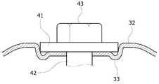
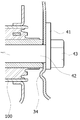
도 6은 본 발명의 일 실시예에 따른 로워암 조립장치에서 캠볼트부를 개략적으로 나타내는 도면이다. 도 6을 참조하면, 본 발명의 일 실시예에 따른 캠볼트부(40)는 고정판부(41)와, 고정막대부(42)와, 고정머리부(43)와, 고정너트부(44)를 포함한다.6 is a view schematically showing a cam bolt in a lower arm assembling apparatus according to an embodiment of the present invention. 6, the
고정판부(41)는 지지돌출부(32) 사이에 삽입되어 지지몸체부(31)에 밀착된다. 일 예로, 고정판부(41)는 원판 형상을 하고, 지지몸체부(31)의 전면에 밀착되며, 양측이 지지돌출부(32)에 밀착되어 좌우 유동이 제한될 수 있다. 고정판부(41)의 원주면을 따라 눈금(411)이 형성되고, 지지몸체부(31)에는 기준선(312)이 형성될 수 있다. 고정판부(41)가 회전되면, 기준선(312)과 눈금(411)을 비교하여, 고정판부(41)의 회전각을 산출할 수 있다.The fixing
고정막대부(42)는 고정판부(41)의 중심에서 치우쳐 관통홀부(311) 방향으로 연장되고, 관통홀부(311)를 관통한다. 일 예로, 고정막대부(42)는 관통홀부(311)와, 로워암(100)과, 고정부(20)를 관통할 수 있다.The fixing
고정머리부(43)는 고정판부(41)의 중심에서 치우쳐 고정막대부(42)의 반대방향으로 연장된다. 고정머리부(43)는 각진 형상을 하여 도구와 맞물릴 수 있으며, 고정막대부(42)와 동일선상에 배치될 수 있다.The fixed head part (43) is biased from the center of the fixed plate part (41) and extends in the direction opposite to the fixed bar part (42). The fixed
고정너트부(44)는 고정막대부(42)에 체결된다. 일 예로, 고정너트부(44)는 고정부(20)의 배면에서 고정막대부(42)에 체결되어 고정막대부(42)를 고정시킬 수 있다. 고정부(20)의 배면과 고정너트부(44) 사이에는 고정와셔부(45)가 배치될 수 있다.The fixing nut portion (44) is fastened to the fixing rod portion (42). For example, the fixing
상기와 같은 구조를 갖는 본 발명의 일 실시예에 따른 로워암 조립장치의 성형과정 및 조립과정을 설명하면 다음과 같다.The forming process and the assembling process of the lower arm assembling apparatus according to one embodiment of the present invention having the above structure will be described as follows.
홀가공을 통해 지지몸체부(31)에 관통홀부(311)가 형성되고, 관통홀부(311)를 사이에 두고 한 쌍의 지지돌출부(32)가 지지몸체부(31)의 전방으로 돌출되도록 가공된다. 그리고, 지지몸체부(31)와 관통홀부(311)의 사이에 위치되는 지지함몰부(33)가 지지몸체부(31)의 전방에서 함몰되도록 가공된다. 또한, 이격된 지지함몰부(33)와 연결되는 지지가이드부(34)가 지지몸체부(31)의 전방에서 함몰되도록 가공된다.The through
가공 완료된 지지몸체부(31)는 멤버연장부(12)에 결합되고, 지지몸체부(31)의 후방에 고정부(20)가 결합된다.The finished
상기한 상태에서, 지지몸체부(31)와 고정부(20) 사이에 로워암(100)을 배치시키고, 캠볼트부(40)를 사용하여 로워암(100)을 지지몸체부(31)와 고정부(20) 사이에 고정시킨다. 이때, 로워암(100)은 지지몸체부(31)의 배면방향으로 돌출된 지지가이드부(34)에 의해 관통홀부(311)로 안내된다.The
캠볼트부(40)의 고정판부(41)는 지지돌출부(32) 사이에 배치되며, 지지돌출부(32)와 인접된 지지함몰부(33)에 의해 지지돌출부(32)의 형상이 유지되어, 고정판부(41)와 지지돌출부(32) 간의 간섭이 방지된다.The fixing
실차 조립시 휠얼라이먼트를 확인하면서 고정판부(41)를 회전시킬 수 있다. 이때, 작업자는 고정판부(41)에 형성되는 눈금(411)과 기준선(312)을 비교하여 고정판부(41)를 조작할 수 있다.The fixing
본 발명의 일 실시예에 따른 로워암 조립장치(1)는 지지부(30)가 캠볼트부(40)의 설치위치를 유도하여 조립성을 개선할 수 있다.The lower
본 발명의 일 실시예에 따른 로워암 조립장치(1)는 한 쌍의 지지돌출부(32) 사이로 캠볼트부(40)가 삽입되어 캠볼트부(40)의 좌우 유동을 제한할 수 있다.The lower
본 발명의 일 실시예에 따른 로워암 조립장치(1)는 관통홀부(311)와 지지돌출부(32) 사이에 지지함몰부(33)가 형성되어 지지돌출부(32)의 형상이 유지됨으로써, 캠볼트부(40)의 고정판부(41)와 지지돌출부(32) 간의 간섭을 방지할 수 있다.The lower
본 발명의 일 실시예에 따른 로워암 조립장치(1)는 지지함몰부(33)가 지지몸체부(31)의 전면에서 함몰되도록 형성됨으로써, 지지몸체부(31)의 강성을 보강할 수 있다.The lower
본 발명의 일 실시예에 따른 로워암 조립장치(1)는 지지가이드부(34)가 로워암(100)을 안내하여 로워암(100)의 조립 위치 선정이 용이하다. 또한, 지지가이드부(34)가 지지몸체부(31)의 전면에서 함몰되도록 형성되어 지지몸체부(31)의 강성을 보강할 수 있다.The lower
본 발명은 도면에 도시된 실시예를 참고로 하여 설명되었으나, 이는 예시적인 것에 불과하며, 당해 기술이 속하는 분야에서 통상의 지식을 가진 자라면 이로부터 다양한 변형 및 균등한 타 실시예가 가능하다는 점을 이해할 것이다. 따라서, 본 발명의 진정한 기술적 보호범위는 아래의 특허청구범위에 의해서 정하여져야 할 것이다.While the present invention has been particularly shown and described with reference to exemplary embodiments thereof, it will be understood by those of ordinary skill in the art that various changes in form and details may be made therein without departing from the spirit and scope of the invention as defined by the appended claims. I will understand. Accordingly, the true scope of protection of the present invention should be defined by the following claims.
10 : 멤버부 11 : 멤버메인부
12 : 멤버연장부 20 : 고정부
30 : 지지부 31 : 지지몸체부
32 : 지지돌출부 33 : 지지함몰부
34 : 지지가이드부 40 : 캠볼트부
41 : 고정판부 42 : 고정막대부
43 : 고정머리부 44 : 고정너트부
45 : 고정와셔부 311 : 관통홀부
312 : 기준선 331 : 함몰직선부
332 : 함몰경사부 411 : 눈금10: Member section 11: Member main section
12: Member extension part 20: Fixed part
30: Support part 31: Support body part
32: support protrusion 33: support depression
34: support guide part 40: cam bolt part
41: fixed plate part 42: fixed rod part
43: fixed head portion 44: fixed nut portion
45: Fixed washer 311: Through hole
312: Reference line 331:
332: depression inclined portion 411: scale
Claims (6)
상기 멤버부에 결합되는 고정부;
상기 멤버부에 결합되고, 상기 고정부와 마주보도록 배치되는 지지부; 및
상기 고정부와 상기 지지부 사이에 배치되는 로워암을 고정시키는 캠볼트부를 포함하고,
상기 지지부는 상기 캠볼트부의 설치위치를 유도하는 것을 특징으로 하는 로워암 조립장치.
A member coupled to the vehicle body;
A fixing portion coupled to the member portion;
A support portion coupled to the member portion and disposed to face the fixing portion; And
And a cam bolt portion for fixing a lower arm disposed between the fixed portion and the support portion,
Wherein the support portion guides the installation position of the cam bolt portion.
상기 캠볼트부가 관통되는 관통홀부가 형성되고, 상기 멤버부에 양단부가 결합되는 지지몸체부; 및
상기 지지몸체부에서 돌출되고, 상기 관통홀부의 양측방향으로 각각 배치되어 상기 캠볼트부를 안내하는 지지돌출부를 포함하는 것을 특징으로 하는 로워암 조립장치.
2. The apparatus of claim 1,
A support body portion having a through hole portion through which the cam bolt portion is inserted and to which both ends are coupled to the member portion; And
And a support protrusion protruding from the support body portion and disposed in both side directions of the through hole to guide the cam bolt portion.
상기 관통홀부와 상기 지지돌출부 사이에 배치되고, 상기 지지몸체부의 전면에서 함몰되어 상기 캠볼트부와 상기 지지돌출부 간의 간섭을 방지하는 지지함몰부를 더 포함하는 것을 특징으로 하는 로워암 조립장치.
3. The apparatus of claim 2, wherein the support
Further comprising a support dimple disposed between the through hole and the support protrusion to prevent interference between the cam bolt and the support protrusion when the support body is recessed from the front surface of the support body.
상기 관통홀부와 상기 지지돌출부 사이에 배치되는 함몰직선부; 및
상기 함몰직선부의 단부에서 상기 지지돌출부 방향으로 경사를 갖도록 형성되는 함몰경사부를 포함하는 것을 특징으로 하는 로워암 조립장치.
4. The apparatus of claim 3, wherein the support depression
A recessed straight portion disposed between the through hole portion and the support projection; And
And a depression inclined portion formed at an end of the depression rectilinear portion so as to have an inclination in the direction of the support projection.
상기 지지몸체부의 배면 방향으로 돌출되어 상기 로워암을 안내하는 지지가이드부를 더 포함하는 것을 특징으로 하는 로워암 조립장치.
3. The apparatus of claim 2, wherein the support
Further comprising: a support guide portion protruding toward the back surface of the support body portion and guiding the lower arm.
상기 지지돌출부 사이에 삽입되어 상기 지지몸체부에 밀착되는 고정판부;
상기 고정판부의 중심에서 치우쳐 연장되고, 상기 관통홀부를 관통하는 고정막대부;
상기 고정판부의 중심에서 치우쳐 연장되는 고정머리부; 및
상기 고정막대부에 체결되는 고정너트부를 포함하는 것을 특징으로 하는 로워암 조립장치.3. The apparatus of claim 2, wherein the cam bolt portion
A fixing plate part inserted between the supporting protrusions and coming into close contact with the supporting body part;
A fixing rod portion biased from the center of the fixing plate portion and penetrating the through hole portion;
A fixed head portion biased from the center of the fixed plate portion; And
And a fastening nut portion fastened to the fastening rod portion.
Priority Applications (1)
| Application Number | Priority Date | Filing Date | Title |
|---|---|---|---|
| KR1020150076469A KR101710372B1 (en) | 2015-05-29 | 2015-05-29 | Assembly device for lower arm |
Applications Claiming Priority (1)
| Application Number | Priority Date | Filing Date | Title |
|---|---|---|---|
| KR1020150076469A KR101710372B1 (en) | 2015-05-29 | 2015-05-29 | Assembly device for lower arm |
Publications (2)
| Publication Number | Publication Date |
|---|---|
| KR20160140179A true KR20160140179A (en) | 2016-12-07 |
| KR101710372B1 KR101710372B1 (en) | 2017-03-06 |
Family
ID=57573914
Family Applications (1)
| Application Number | Title | Priority Date | Filing Date |
|---|---|---|---|
| KR1020150076469A KR101710372B1 (en) | 2015-05-29 | 2015-05-29 | Assembly device for lower arm |
Country Status (1)
| Country | Link |
|---|---|
| KR (1) | KR101710372B1 (en) |
Cited By (2)
| Publication number | Priority date | Publication date | Assignee | Title |
|---|---|---|---|---|
| KR20180093658A (en) * | 2017-02-14 | 2018-08-22 | 현대모비스 주식회사 | Toe controlling device for vehicle |
| KR20200132472A (en) * | 2019-05-17 | 2020-11-25 | 현대모비스 주식회사 | Rear cross member for vehicle |
Families Citing this family (1)
| Publication number | Priority date | Publication date | Assignee | Title |
|---|---|---|---|---|
| US10899186B2 (en) * | 2019-02-12 | 2021-01-26 | Mahindra N.A. Tech Center | Cam adjustment mechanism for vehicle suspension control arm mount |
Citations (2)
| Publication number | Priority date | Publication date | Assignee | Title |
|---|---|---|---|---|
| CN201951198U (en) * | 2010-12-27 | 2011-08-31 | 东风汽车公司 | Automobile four-link rear suspension |
| KR20130065436A (en) * | 2011-12-09 | 2013-06-19 | 현대자동차주식회사 | Cross member assembly for vehicles |
-
2015
- 2015-05-29 KR KR1020150076469A patent/KR101710372B1/en active IP Right Grant
Patent Citations (2)
| Publication number | Priority date | Publication date | Assignee | Title |
|---|---|---|---|---|
| CN201951198U (en) * | 2010-12-27 | 2011-08-31 | 东风汽车公司 | Automobile four-link rear suspension |
| KR20130065436A (en) * | 2011-12-09 | 2013-06-19 | 현대자동차주식회사 | Cross member assembly for vehicles |
Cited By (2)
| Publication number | Priority date | Publication date | Assignee | Title |
|---|---|---|---|---|
| KR20180093658A (en) * | 2017-02-14 | 2018-08-22 | 현대모비스 주식회사 | Toe controlling device for vehicle |
| KR20200132472A (en) * | 2019-05-17 | 2020-11-25 | 현대모비스 주식회사 | Rear cross member for vehicle |
Also Published As
| Publication number | Publication date |
|---|---|
| KR101710372B1 (en) | 2017-03-06 |
Similar Documents
| Publication | Publication Date | Title |
|---|---|---|
| JP2011168190A (en) | Steering position adjusting device | |
| KR101710372B1 (en) | Assembly device for lower arm | |
| JP4639248B2 (en) | Body front structure | |
| US10093343B2 (en) | Steering device | |
| KR101338966B1 (en) | Suspension device for automobile | |
| JP4511389B2 (en) | Steering handle position adjustment device | |
| US9802637B2 (en) | Steering device | |
| KR101613470B1 (en) | Lower arm for vehicle | |
| JP6805591B2 (en) | Vehicle instrument panel | |
| KR101127802B1 (en) | Suspension device for automobile and manufacturing method thereof | |
| KR102539426B1 (en) | Rear cross member for vehicle | |
| JP2019034700A (en) | Vehicle fuel tank attachment structure and vehicle fuel tank attachment method | |
| JP2002331860A (en) | Locating structure for long slide rail | |
| CN217530600U (en) | Compact clamp | |
| JP2019038468A (en) | Propeller shaft guard | |
| JP7122222B2 (en) | Damper mount mounting structure | |
| KR20150033479A (en) | Bush device of lower arm | |
| KR20220075803A (en) | Front cross member assembly of vehicle | |
| KR20190021564A (en) | Trailing arm for suspension apparatus | |
| KR100394732B1 (en) | Crash pad having a fixing bracket | |
| JP6615665B2 (en) | Knuckle bracket and suspension system | |
| JP7042147B2 (en) | Center console assembly structure and center console assembly method | |
| KR20170111007A (en) | A knuckle for a vechicle comprising a clamping surface and a knuckle assembly for a vechicle comprising the knuckle | |
| JP6061993B1 (en) | Front subframe stay fastening structure and front subframe body assembly method | |
| JPH1035239A (en) | Stabilizer supporting structure |
Legal Events
| Date | Code | Title | Description |
|---|---|---|---|
| AMND | Amendment | ||
| E601 | Decision to refuse application | ||
| X091 | Application refused [patent] | ||
| AMND | Amendment | ||
| X701 | Decision to grant (after re-examination) | ||
| FPAY | Annual fee payment |
Payment date: 20200301 Year of fee payment: 4 |