KR20160074010A - Case structure for fluid pressure device - Google Patents
Case structure for fluid pressure device Download PDFInfo
- Publication number
- KR20160074010A KR20160074010A KR1020167015179A KR20167015179A KR20160074010A KR 20160074010 A KR20160074010 A KR 20160074010A KR 1020167015179 A KR1020167015179 A KR 1020167015179A KR 20167015179 A KR20167015179 A KR 20167015179A KR 20160074010 A KR20160074010 A KR 20160074010A
- Authority
- KR
- South Korea
- Prior art keywords
- case
- portions
- unit
- filter
- fluid
- Prior art date
Links
- 239000012530 fluid Substances 0.000 title claims abstract description 106
- 230000002093 peripheral effect Effects 0.000 claims abstract description 17
- 239000000428 dust Substances 0.000 claims description 16
- 239000000463 material Substances 0.000 claims description 12
- 230000001105 regulatory effect Effects 0.000 claims description 12
- 239000011347 resin Substances 0.000 claims description 9
- 229920005989 resin Polymers 0.000 claims description 9
- 238000006073 displacement reaction Methods 0.000 claims description 8
- 230000007246 mechanism Effects 0.000 claims description 8
- 230000008878 coupling Effects 0.000 claims description 4
- 238000010168 coupling process Methods 0.000 claims description 4
- 238000005859 coupling reaction Methods 0.000 claims description 4
- 238000000034 method Methods 0.000 claims 4
- 230000035699 permeability Effects 0.000 abstract description 5
- 239000012780 transparent material Substances 0.000 abstract description 3
- 239000003921 oil Substances 0.000 description 16
- 239000010687 lubricating oil Substances 0.000 description 15
- XLYOFNOQVPJJNP-UHFFFAOYSA-N water Substances O XLYOFNOQVPJJNP-UHFFFAOYSA-N 0.000 description 7
- 230000008859 change Effects 0.000 description 5
- 239000013013 elastic material Substances 0.000 description 5
- 238000009434 installation Methods 0.000 description 5
- 239000002904 solvent Substances 0.000 description 5
- 239000004417 polycarbonate Substances 0.000 description 4
- 229920000515 polycarbonate Polymers 0.000 description 4
- 239000000314 lubricant Substances 0.000 description 3
- NIXOWILDQLNWCW-UHFFFAOYSA-N acrylic acid group Chemical group C(C=C)(=O)O NIXOWILDQLNWCW-UHFFFAOYSA-N 0.000 description 2
- 230000000694 effects Effects 0.000 description 2
- -1 polypropylene Polymers 0.000 description 2
- 239000004698 Polyethylene Substances 0.000 description 1
- 239000004743 Polypropylene Substances 0.000 description 1
- 230000009471 action Effects 0.000 description 1
- 230000033228 biological regulation Effects 0.000 description 1
- 230000006835 compression Effects 0.000 description 1
- 238000007906 compression Methods 0.000 description 1
- 238000012790 confirmation Methods 0.000 description 1
- 239000000470 constituent Substances 0.000 description 1
- 239000002657 fibrous material Substances 0.000 description 1
- 230000006698 induction Effects 0.000 description 1
- 230000001050 lubricating effect Effects 0.000 description 1
- 238000005461 lubrication Methods 0.000 description 1
- 230000000149 penetrating effect Effects 0.000 description 1
- 229920000573 polyethylene Polymers 0.000 description 1
- 229920001155 polypropylene Polymers 0.000 description 1
- 230000002265 prevention Effects 0.000 description 1
- 239000010409 thin film Substances 0.000 description 1
Images

Classifications
-
- B—PERFORMING OPERATIONS; TRANSPORTING
- B01—PHYSICAL OR CHEMICAL PROCESSES OR APPARATUS IN GENERAL
- B01D—SEPARATION
- B01D46/00—Filters or filtering processes specially modified for separating dispersed particles from gases or vapours
- B01D46/24—Particle separators, e.g. dust precipitators, using rigid hollow filter bodies
- B01D46/2403—Particle separators, e.g. dust precipitators, using rigid hollow filter bodies characterised by the physical shape or structure of the filtering element
- B01D46/2411—Filter cartridges
- B01D46/2414—End caps including additional functions or special forms
-
- B—PERFORMING OPERATIONS; TRANSPORTING
- B01—PHYSICAL OR CHEMICAL PROCESSES OR APPARATUS IN GENERAL
- B01D—SEPARATION
- B01D46/00—Filters or filtering processes specially modified for separating dispersed particles from gases or vapours
- B01D46/0002—Casings; Housings; Frame constructions
- B01D46/0005—Mounting of filtering elements within casings, housings or frames
-
- B—PERFORMING OPERATIONS; TRANSPORTING
- B01—PHYSICAL OR CHEMICAL PROCESSES OR APPARATUS IN GENERAL
- B01D—SEPARATION
- B01D35/00—Filtering devices having features not specifically covered by groups B01D24/00 - B01D33/00, or for applications not specifically covered by groups B01D24/00 - B01D33/00; Auxiliary devices for filtration; Filter housing constructions
- B01D35/30—Filter housing constructions
-
- B—PERFORMING OPERATIONS; TRANSPORTING
- B01—PHYSICAL OR CHEMICAL PROCESSES OR APPARATUS IN GENERAL
- B01D—SEPARATION
- B01D36/00—Filter circuits or combinations of filters with other separating devices
- B01D36/003—Filters in combination with devices for the removal of liquids
- B01D36/006—Purge means
-
- B—PERFORMING OPERATIONS; TRANSPORTING
- B01—PHYSICAL OR CHEMICAL PROCESSES OR APPARATUS IN GENERAL
- B01D—SEPARATION
- B01D46/00—Filters or filtering processes specially modified for separating dispersed particles from gases or vapours
- B01D46/0002—Casings; Housings; Frame constructions
- B01D46/0004—Details of removable closures, lids, caps or filter heads
-
- B—PERFORMING OPERATIONS; TRANSPORTING
- B01—PHYSICAL OR CHEMICAL PROCESSES OR APPARATUS IN GENERAL
- B01D—SEPARATION
- B01D46/00—Filters or filtering processes specially modified for separating dispersed particles from gases or vapours
- B01D46/0002—Casings; Housings; Frame constructions
- B01D46/001—Means for connecting filter housings to supports
-
- B—PERFORMING OPERATIONS; TRANSPORTING
- B01—PHYSICAL OR CHEMICAL PROCESSES OR APPARATUS IN GENERAL
- B01D—SEPARATION
- B01D46/00—Filters or filtering processes specially modified for separating dispersed particles from gases or vapours
- B01D46/0084—Filters or filtering processes specially modified for separating dispersed particles from gases or vapours provided with safety means
-
- B—PERFORMING OPERATIONS; TRANSPORTING
- B01—PHYSICAL OR CHEMICAL PROCESSES OR APPARATUS IN GENERAL
- B01D—SEPARATION
- B01D46/00—Filters or filtering processes specially modified for separating dispersed particles from gases or vapours
- B01D46/24—Particle separators, e.g. dust precipitators, using rigid hollow filter bodies
-
- B—PERFORMING OPERATIONS; TRANSPORTING
- B01—PHYSICAL OR CHEMICAL PROCESSES OR APPARATUS IN GENERAL
- B01D—SEPARATION
- B01D46/00—Filters or filtering processes specially modified for separating dispersed particles from gases or vapours
- B01D46/42—Auxiliary equipment or operation thereof
- B01D46/4254—Allowing or improving visual supervision, e.g. lamps, transparent parts, windows
-
- F—MECHANICAL ENGINEERING; LIGHTING; HEATING; WEAPONS; BLASTING
- F15—FLUID-PRESSURE ACTUATORS; HYDRAULICS OR PNEUMATICS IN GENERAL
- F15B—SYSTEMS ACTING BY MEANS OF FLUIDS IN GENERAL; FLUID-PRESSURE ACTUATORS, e.g. SERVOMOTORS; DETAILS OF FLUID-PRESSURE SYSTEMS, NOT OTHERWISE PROVIDED FOR
- F15B21/00—Common features of fluid actuator systems; Fluid-pressure actuator systems or details thereof, not covered by any other group of this subclass
- F15B21/04—Special measures taken in connection with the properties of the fluid
- F15B21/041—Removal or measurement of solid or liquid contamination, e.g. filtering
-
- B—PERFORMING OPERATIONS; TRANSPORTING
- B01—PHYSICAL OR CHEMICAL PROCESSES OR APPARATUS IN GENERAL
- B01D—SEPARATION
- B01D2201/00—Details relating to filtering apparatus
- B01D2201/29—Filter cartridge constructions
- B01D2201/291—End caps
-
- B—PERFORMING OPERATIONS; TRANSPORTING
- B01—PHYSICAL OR CHEMICAL PROCESSES OR APPARATUS IN GENERAL
- B01D—SEPARATION
- B01D2201/00—Details relating to filtering apparatus
- B01D2201/29—Filter cartridge constructions
- B01D2201/291—End caps
- B01D2201/295—End caps with projections extending in a radial outward direction, e.g. for use as a guide, spacing means
-
- B—PERFORMING OPERATIONS; TRANSPORTING
- B01—PHYSICAL OR CHEMICAL PROCESSES OR APPARATUS IN GENERAL
- B01D—SEPARATION
- B01D2201/00—Details relating to filtering apparatus
- B01D2201/30—Filter housing constructions
- B01D2201/307—Filtering elements contained in an insert body mounted in a filter housing (double casing), e.g. to avoid contamination when removing or replacing the filter element
-
- B—PERFORMING OPERATIONS; TRANSPORTING
- B01—PHYSICAL OR CHEMICAL PROCESSES OR APPARATUS IN GENERAL
- B01D—SEPARATION
- B01D2201/00—Details relating to filtering apparatus
- B01D2201/30—Filter housing constructions
- B01D2201/309—Housings with transparent parts
-
- B—PERFORMING OPERATIONS; TRANSPORTING
- B01—PHYSICAL OR CHEMICAL PROCESSES OR APPARATUS IN GENERAL
- B01D—SEPARATION
- B01D2201/00—Details relating to filtering apparatus
- B01D2201/40—Special measures for connecting different parts of the filter
- B01D2201/4084—Snap or Seeger ring connecting means
-
- F—MECHANICAL ENGINEERING; LIGHTING; HEATING; WEAPONS; BLASTING
- F15—FLUID-PRESSURE ACTUATORS; HYDRAULICS OR PNEUMATICS IN GENERAL
- F15B—SYSTEMS ACTING BY MEANS OF FLUIDS IN GENERAL; FLUID-PRESSURE ACTUATORS, e.g. SERVOMOTORS; DETAILS OF FLUID-PRESSURE SYSTEMS, NOT OTHERWISE PROVIDED FOR
- F15B21/00—Common features of fluid actuator systems; Fluid-pressure actuator systems or details thereof, not covered by any other group of this subclass
- F15B21/04—Special measures taken in connection with the properties of the fluid
- F15B21/048—Arrangements for compressed air preparation, e.g. comprising air driers, air condensers, filters, lubricators or pressure regulators
-
- Y—GENERAL TAGGING OF NEW TECHNOLOGICAL DEVELOPMENTS; GENERAL TAGGING OF CROSS-SECTIONAL TECHNOLOGIES SPANNING OVER SEVERAL SECTIONS OF THE IPC; TECHNICAL SUBJECTS COVERED BY FORMER USPC CROSS-REFERENCE ART COLLECTIONS [XRACs] AND DIGESTS
- Y10—TECHNICAL SUBJECTS COVERED BY FORMER USPC
- Y10T—TECHNICAL SUBJECTS COVERED BY FORMER US CLASSIFICATION
- Y10T137/00—Fluid handling
- Y10T137/6851—With casing, support, protector or static constructional installations
- Y10T137/7036—Jacketed
Landscapes
- Chemical & Material Sciences (AREA)
- Chemical Kinetics & Catalysis (AREA)
- Physics & Mathematics (AREA)
- Engineering & Computer Science (AREA)
- Geometry (AREA)
- Analytical Chemistry (AREA)
- Fluid Mechanics (AREA)
- Mechanical Engineering (AREA)
- General Engineering & Computer Science (AREA)
- Filtering Of Dispersed Particles In Gases (AREA)
- Filtration Of Liquid (AREA)
Abstract
본 발명은, 유체압 기기의 케이스 구조에 관한 것으로, 유체압 유닛(10)을 구성하는 필터(12)는, 제1 바디(20)와, 상기 제1 바디(20)의 하부에 연결되는 케이스 유닛(22)과, 상기 케이스 유닛(22)의 내부에 수납되는 필터 유닛(24)을 구비한다. 이러한 케이스 유닛(22)은, 투과성을 지닌 투명한 재료로 이루어진 바닥을 가진 통 형상으로 형성된 외부 케이스(40)와, 상기 외부 케이스(40)의 내부에 삽입되는 내부 케이스(42)로 이루어진다. 그리고, 케이스 유닛(22)을 제1 바디(20)의 하부에 개방된 장착홀(36)에 삽입하고, 회전시킴으로써 상기 케이스 유닛(22)의 외주면에 설치된 돌출부(58) 및 지지벽(56)을, 상기 장착홀(36)에 설치된 지지부(38)에 결합시켜 연결 상태가 된다.A filter (12) constituting a fluid pressure unit (10) includes a first body (20), a case connected to a lower portion of the first body (20) And a filter unit (24) housed in the case unit (22). The case unit 22 includes an outer case 40 formed in a cylindrical shape having a bottom made of a transparent material having permeability and an inner case 42 inserted into the outer case 40. The protrusion 58 and the support wall 56 provided on the outer peripheral surface of the case unit 22 are inserted into the mounting hole 36 opened in the lower portion of the first body 20, To the support portion (38) provided in the mounting hole (36).
Description
본 발명은, 내부에 유체가 흐르는 유체압 기기에 이용되는 케이스 구조에 관한 것이다.The present invention relates to a case structure used in a fluid pressure device in which a fluid flows.
본 출원인은, 일본공개실용 실개평5-9618호 공보에 개시된 바와 같이, 압력 유체 중의 먼지 등을 제거하는 필터(유체압 기기)를 제안하였다. 이러한 필터는, 압력 유체가 공급, 배출되는 포트를 가진 바디와, 상기 바디의 하부에 설치된 중공 형상의 케이스와, 상기 케이스의 내부에 수용되어 먼지 등을 제거할 수 있는 필터 엘레먼트를 구비한다. 또한, 케이스의 외주측에는, 상기 케이스를 감싸도록 케이스 커버가 형성되고, 상기 케이스 커버에는, 케이스 내의 필터 엘레먼트의 상황을 외부로부터 확인하기 위한 확인창이 형성되어 있다.The present applicant has proposed a filter (fluid pressure device) for removing dust and the like in a pressure fluid as disclosed in Japanese Laid-Open Utility Model Publication No. 5-9618. Such a filter includes a body having a port through which a pressurized fluid is supplied and discharged, a hollow case provided at a lower portion of the body, and a filter element accommodated in the case to remove dust and the like. A case cover is formed on the outer circumferential side of the case so as to surround the case, and the case cover is provided with a confirmation window for confirming the situation of the filter elements in the case from the outside.
본 발명의 일반적인 목적은, 바디에 대하여 케이스를 확실하고 용이하게 연결할 수 있으며, 외부로부터 케이스 내부를 더욱 확실하고 용이하게 시각적으로 인식할 수 있으면서도, 상기 케이스의 내구성의 향상시킬 수 있는 유체압 기기의 케이스 구조를 제공하는 것에 있다.It is a general object of the present invention to provide a fluid pressure device capable of reliably and easily connecting a case to a body and capable of visually recognizing the inside of the case more reliably and easily from the outside and improving the durability of the case To provide a case structure.
본 발명은, 압력 유체가 내부로 공급되는 케이스를 가진 유체압 기기의 케이스 구조에 있어서,The present invention provides a case structure of a fluid pressure device having a case in which a pressure fluid is supplied to the inside,
상기 유체압 기기는, 상기 압력 유체가 공급, 배출되는 포트를 가진 바디와,The fluid pressure device includes a body having a port through which the pressure fluid is supplied and discharged,
상기 바디의 장착홀에 연결되고, 내부가 상기 포트와 연통하는 바닥을 가진 통 형상의 케이스를 구비하며,And a tubular case connected to the mounting hole of the body and having a bottom in communication with the port,
상기 케이스는, 내부를 시각적으로 인식할 수 있는 투과성을 지니고, 제1 케이스부와, 상기 제1 케이스부의 내부에 설치된 제2 케이스부를 구비하고, 상기 제1 및 제2 케이스부의 적어도 어느 하나의 일측 외주면에 형성된 제1 결합부가, 상기 장착홀의 내주면에 형성되는 제2 결합부와 결합되는 것을 특징으로 한다.Wherein the case has a first case portion and a second case portion provided inside the first case portion, the first case portion having transparency for visually recognizing the inside thereof, and at least one of the first case portion and the second case portion And the first engaging portion formed on the outer circumferential surface is engaged with the second engaging portion formed on the inner circumferential surface of the mounting hole.
본 발명에 의하면, 유체압 기기에 있어서, 압력 유체가 내부에 도입되는 케이스를, 그 내부를 시각적으로 인식할 수 있는 투과성을 지니도록 형성하고, 제1 케이스부와, 상기 제1 케이스부의 내부에 형성되는 제2 케이스부로 이루어지도록 구성함과 동시에, 상기 케이스의 외주면에 제1 결합부를 설치하고, 바디의 장착홀에 형성된 제2 결합부에 결합시킴으로써 연결할 수 있다.According to the present invention, in the fluid pressure device, the case in which the pressure fluid is introduced into the case is formed so as to have a transparency visually recognizing the inside thereof, and the first case portion and the second case portion And a second engaging portion formed on a mounting hole of the body. The first engaging portion is formed on an outer circumferential surface of the case, and the first engaging portion is engaged with the second engaging portion.
따라서, 케이스를, 바디의 장착홀에 형성된 제2 결합부에 결합시킴으로써 확실하고 용이하게 상기 바디에 대하여 케이스를 연결할 수 있음과 동시에, 상기 케이스의 내부를 외부로부터 시각적으로 인식할 수 있으므로, 상기 내부에 공급되는 압력 유체의 상태(예를 들면, 함유된 먼지나 수분의 양)를 상기 케이스의 외주면 전체 면으로부터 확실하고 용이하게 확인할 수 있다.Therefore, by connecting the case to the second engaging portion formed in the mounting hole of the body, the case can be reliably and easily connected to the body, and the inside of the case can be visually recognized from the outside, (For example, the amount of dust and water contained) supplied to the pressure fluid from the entire outer peripheral surface of the case can be reliably and easily confirmed.
또한, 제2 케이스부가, 제1 케이스의 내부에 형성되고, 상기 제2 케이스부가 외부에 노출되지 않으므로, 예를 들면 유체압 기기의 설치 환경 하에서 가스나 용제 등이 상기 제2 케이스부에 대하여 부착되는 것을 방지할 수 있다. 따라서, 제2 케이스부의 내구성을 향상시킬 수 있다.In addition, since the second case part is formed inside the first case and the second case part is not exposed to the outside, for example, gas, solvent or the like is adhered to the second case part Can be prevented. Therefore, the durability of the second case portion can be improved.
첨부한 도면과 함께 본 발명의 바람직한 실시 형태가 실제예를 통하여 설명되는 아래의 설명으로부터 본 발명의 상기 목적 및 다른 목적, 특징 및 이점이 더욱 명확하게 될 것이다.BRIEF DESCRIPTION OF THE DRAWINGS The above and other objects, features and advantages of the present invention will become more apparent from the following description taken in conjunction with the accompanying drawings, in which preferred embodiments of the invention are shown by way of illustration.
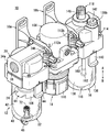
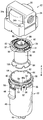
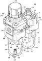
도 1은 본 발명의 제1 실시 형태에 따른 케이스 구조가 적용된 유체압 유닛의 외관 사시도이다.
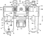
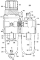
도 2는 도 1에 나타낸 유체압 유닛의 정면도이다.
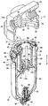
도 3은 도 1의 유체압 유닛을 구성하는 필터의 분해 단면 사시도이다.
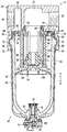
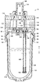
도 4는 도 3에 나타낸 필터의 전체 단면도이다.
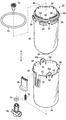
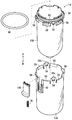
도 5는 도 1의 유체압 유닛을 구성하는 필터의 분해 사시도이다.
도 6은 도 5의 필터를 구성하는 케이스 유닛의 분해 사시도이다.
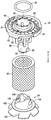
도 7은 도 5의 필터를 구성하는 필터 유닛의 분해 사시도이다.
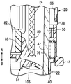
도 8은, 도 8a는 도 2의 VIIIA-VIIIA선에 따른 단면도이며, 도 8b는 도 8a의 릴리즈 버튼이 하강하여, 제1 바디와 케이스 유닛의 회전 규제 상태가 해제된 상태를 나타낸 단면도이다.
도 9는 도 1의 유체압 유닛을 구성하는 루브리케이터(lubricator)의 전체 단면도이다.
도 10은 도 1의 루브리케이터를 구성하는 케이스 유닛의 분해 사시도이다.
도 11은 본 발명의 제2 실시 형태에 따른 케이스 구조가 적용된 유체압 유닛의 외관 사시도이다.
도 12는 도 11에 나타낸 유체압 유닛의 정면도이다.
도 13은 도 12의 유체압 유닛을 구성하는 필터 레귤레이터의 전체 단면도이다.1 is an external perspective view of a fluid pressure unit to which a case structure according to a first embodiment of the present invention is applied.
2 is a front view of the fluid pressure unit shown in Fig.
3 is an exploded cross-sectional perspective view of a filter constituting the fluid pressure unit of FIG.
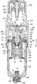
4 is an overall sectional view of the filter shown in Fig.
5 is an exploded perspective view of a filter constituting the fluid pressure unit of FIG.
Fig. 6 is an exploded perspective view of the case unit constituting the filter of Fig. 5;
Fig. 7 is an exploded perspective view of the filter unit constituting the filter of Fig. 5;
FIG. 8A is a cross-sectional view taken along the line VIIIA-VIIIA of FIG. 2, and FIG. 8B is a cross-sectional view showing a state in which the release button of FIG. 8A is lowered and the rotation regulation state of the first body and the case unit is released.
Fig. 9 is an overall sectional view of a lubricator constituting the fluid pressure unit of Fig. 1. Fig.
10 is an exploded perspective view of a case unit constituting the lubricator of FIG.
11 is an external perspective view of a fluid pressure unit to which a case structure according to a second embodiment of the present invention is applied.
12 is a front view of the fluid pressure unit shown in Fig.
13 is an overall sectional view of a filter regulator constituting the fluid pressure unit of Fig.
도 1에 있어서, 참조부호 10은, 본 발명의 제1 실시 형태에 따른 케이스 구조가 적용된 유체압 기기를 포함하는 유체압 유닛(10)을 나타낸다.1,
*이러한 유체압 유닛(10)은, 도 1 및 도 2와 같이, 압력 유체 중에 포함된 먼지 등을 제거하는 필터(12)와, 상기 압력 유체의 압력을 감압하는 레귤레이터(14)와, 상기 압력 유체에 대하여 윤활유를 혼합하는 루브리케이터(16, lubricator)와, 상기 필터(12), 레귤레이터(14) 및 루브리케이터(16)를 상호 연결하는 접속 장치(18a, 18b)로 구성딘다.1 and 2, the
위에서 설명한 필터(12), 레귤레이터(14) 및 루브리케이터(16)가, 그 내부에 압력 유체가 공급되는 유체압 기기로서 기능하고, 상기 레귤레이터(14)가 상기 필터(12)와 루브리케이터(16) 사이가 되도록 배치된다.The
필터(12)는, 도 1 내지 도 7에 나타낸 바와 같이, 제1 바디(20, 바디)와, 상기 제1 바디(20)의 하부에 연결되는 케이스 유닛(22, 케이스)과, 상기 케이스 유닛(22)의 내부에 장전되는 필터 유닛(24)을 포함한다.1 to 7, the
제1 바디(20)에는, 압력 유체가 공급, 배출되는 제1 및 제2 포트(26, 28, 포트)가 측면에 형성되고, 대략 수평 방향으로 각각 개방된다(도 4 참조). 제1 포트(26)는, 도시하지 않은 배관과 접속되고, 상기 배관을 통하여 압력 유체가 공급됨과 동시에, 제1 바디(20)의 내부에 있어서 축 방향(화살표 A, B 방향)으로 연장 형성된 제1 연통로(30)와 연통된다.In the
제2 포트(28)는, 제1 포트(26)에 공급되는 압력 유체가 후술할 레귤레이터(14)로 배출되고, 상기 제1 바디(20)의 대략 중앙부에 있어서 축 방향(화살표 A, B 방향)으로 연장 형성된 제2 연통로(32)와 연통된다.The
또한, 제1 바디(20)의 측면에는, 제1 및 제2 포트(26, 28)가 형성된 끝면의 외측 가장자리부에 상호 대향하여 형성된 한 쌍의 결합용 돌출부(34a, 34b)가 설치된다.A pair of
제1 바디(20)의 하부에는, 케이스 유닛(22)이 삽입되는 장착홀(36)이 개방되며, 단면이 대략 원 형상으로 형성된 상기 장착홀(36)에는, 그 외주측에 상기 제1 연통로(30)가 연통되고, 상기 장착홀(36)의 중앙부에 제2 연통로(32)가 연통하고 있다.The
이러한 장착홀(36)의 내주면에는, 도 3 및 도 4에 나타난 바와 같이, 반경 내측 방향으로 돌출된 복수의 지지부(38, 제2 결합부)가 형성되고, 상기 지지부(38)에는, 케이스 유닛(22)을 구성하는 내부 케이스(42, 제2 케이스부)의 돌출부(58, 제1 결합부)가 결합된다. 지지부(38)는, 장착홀(36)의 둘레 방향을 따라 상호 등간격으로 이격하도록 형성된다.3 and 4, a plurality of support portions 38 (second engagement portions) protruding radially inward are formed on the inner circumferential surface of the
케이스 유닛(22)은, 바닥을 가진 통 형상으로 형성된 외부 케이스(40)와, 해당 외부 케이스(40)의 내부에 삽입되는 내부 케이스(42)와, 상기 외부 케이스(40)에 대하여 자유로이 위치 변경 가능하게 설치되는 릴리즈 버튼(44, 조작 버튼)과, 상기 외부 케이스(40) 및 내부 케이스(42)의 바닥부에 설치된 드레인 코크(46)를 포함한다.The
외부 케이스(40)는 예를 들면, 투과성을 지닌 투명한 수지제 재료(아크릴, 폴리카보네이트 등)로 대략 일정 직경과, 축 방향(화살표 A, B 방향)에 소정 길이로 형성되고, 그 바닥부가 반구 형상으로 형성됨과 동시에 상단부가 개방되어 있다.The
외부 케이스(40)의 상부에는, 상측(화살표 A 방향)을 향하여 축 방향으로 돌출된 한 쌍의 접속편(48a, 48b, 도 6 참조)이 형성됨과 동시에, 일측의 접속편(48a)과 타측의 접속편(48b) 사이가 되는 위치에, 후술할 릴리즈 버튼(44)이 장착되는 버튼홀(50)이 형성된다. 접속편(48a, 48b)은, 외부 케이스(40)의 반경 방향으로 탄성 변형 가능하게 형성되고, 대략 중앙부에는 내부 케이스(42)의 돌기부(52)가 결합되는 홀부(54)를 구비한다. 그리고, 홀부(54)는, 대략 사각 형상으로 개방되어 형성된다.A pair of connecting
또한, 버튼홀(50)은, 외부 케이스(40)의 상단부로부터 하측(화살표 B 방향)을 향하여 축 방향으로 연장 형성되고, 대략 직사각 형상으로 절결되어 형성된다.The
그리고, 외부 케이스(40)의 상부에는, 반경 외측 방향을 향하여 서서히 직경이 커지는 복수의 지지벽(56)이 형성되고, 해당 지지벽(56)은, 상기 외부 케이스(40)의 둘레 방향을 따라 상호 대략 등간격으로 이격하여 형성됨과 동시에, 상기 외부 케이스(40)의 내부에 내부 케이스(42)가 수납되었을 때, 그 돌출부(58)를 지지할 수 있게 형성된다.A plurality of
한편, 외부 케이스(40)의 바닥부에는, 축선 위가 되는 대략 중앙부에 내부 케이스(42)의 드레인 보스(68, 후술할 것임)가 삽입되는 보스홀(60)이 형성된다.A
내부 케이스(42)는, 외부 케이스(40)와 같이, 예를 들면, 투과성을 지닌 투명한 수지제 재료(폴리카보네이트 등)로 대략 일정 직경과, 축 방향(화살표 A, B 방향)에 소정 길이로 형성되고, 그 바닥부가 반구 형상으로 형성됨과 동시에 상단부가 개방되어 있다. 그리고, 내부 케이스(42)의 외주 직경은, 외부 케이스(40)의 내주 직경과 대략 동일하거나 약간 작게 되도록 설정된다(도 4 참조). 그리고, 내부 케이스(42)는, 외부 케이스(40)의 내부에 수납되고, 해당 외부 케이스(40)의 외부에 노출되는 일은 없다.The
또한, 내부 케이스(42)의 상부에는, 그 외주면으로부터 반경 외측 방향으로 돌출된 복수의 돌출부(58)가 형성되고, 상기 내부 케이스(42)의 둘레 방향을 따라 상호 대략 등간격으로 이격하여 형성된다. 이러한 돌출부(58) 및 지지벽(56)의 수량은, 제1 바디(20)의 지지부(38)와 같은 수로 설정되고, 인접한 돌출부(58) 및 지지벽(56)끼리의 간격도, 인접한 지지부(38)끼리의 간격과 동일하도록 설정된다.The upper portion of the
돌출부(58)의 하부에는, 상측을 향하여 경사진 경사면을 구비하는 한편, 상기 돌출부(58)의 상면은, 대략 수평 방향으로 연장 형성된 평면 형상으로 형성된다. 그리고, 내부 케이스(42)가 외부 케이스(40)의 내부에 수납되었을 때, 돌출부(58)의 경사면이 지지벽(56)에 각각 맞닿아 접하여 지지된다.The
또한, 인접한 2개의 돌출부(58) 사이에는, 내부 케이스(42)의 외주면에 대하여 소정 높이로 돌출된 한 쌍의 돌기부(52)가 형성되고, 외부 케이스(40)에 대하여 내부 케이스(42)를 조립할 때, 단면이 대략 직사각 형상으로 형성되는 돌기부(52)가, 접속편(48a, 48b)의 홀부(54)에 결합된다. 따라서, 한 쌍의 접속편(48a, 48b)에 의하여 외부 케이스(40)와 내부 케이스(42)가 상호 견고하게 연결된다.A pair of
그리고, 내부 케이스(42)의 상부에는, 상기 내부 케이스(42)의 외주면에 대하여 반경 내측 방향으로 직경이 축소되는 링 형상 벽(62)이 형성되고, 해당 링 형상 벽(62)에는, 그 상부로부터 돌출된 복수의 후크(64)가 형성됨과 동시에, 링 형상 벽(62)의 외주측에는 탄성 재료로 이루어진 제1 씰 링(66)이 장착된다. 이러한 후크(64)는, 내부 케이스(42)의 둘레 방향을 따라 상호 등간격으로 이격하여, 그 상단부가 반경 외측 방향으로 돌출된다. 바꿔말하면, 후크(64)는, 그 상단부가 반경 외측 방향을 향하여 돌출된 단면이 L자 형성으로 형성된다.A ring-shaped
그리고, 내부 케이스(42)를 포함하는 케이스 유닛(22)의 내부에 필터 유닛(24)이 수납될 때, 상기 필터 유닛(24)을 구성하는 디플렉터(82, deflector, 후술할 것임)가 상기 후크(64)에 의하여 지지된다.When the
한편, 내부 케이스(42)의 바닥부에는, 축선 위가 되는 대략 중앙부에 축 방향(화살표 A, B 방향)을 향하여 돌출된 드레인 보스(68)가 설치되고, 해당 드레인 보스(68)의 내부에는 드레인 코크(46)가 삽입되는 드레인 홀(70)이 형성된다.A
그리고, 외부 케이스(40)에 대하여 내부 케이스(42)를 조립할 때, 상기 외부 케이스(40)의 보스홀(60)에 내부 케이스(42)의 드레인 보스(68)가 삽입 관통된 후, 드레인 홀(70)에 드레인 코크(46)가 삽입(예를 들면, 가볍게 눌러 넣음)되고, 상기 내부 케이스(42)의 내부로부터 고정용 플러그(72)로 고정된다.After the
그리고, 드레인 코크(46)의 외주면에는, 탄성 재료로 이루어진 제2 씰 링(74)이 링 형상 홈을 통하여 장착되고, 드레인 홀(70)에 삽입되었을 때 해당 드레인 홀(70)의 내주면에 맞닿아 접함으로써 상기 드레인 코크(46)와 드레인 홀(70) 사이를 통한 압력 유체의 누출이 방지된다.A
릴리즈 버튼(44)은, 단면이 L자 형상인 블럭체로 이루어지고, 외측으로 돌출된 부위가 외부 케이스(40)에 대하여 외측 그리고 하측(화살표 B 방향)이 되도록 버튼 홀(50)에 대하여 장착된다. 이러한 릴리즈 버튼(44)은, 버튼 홀(50)을 따라 상하 방향(화살표 A, B 방향)으로 자유로이 위치 변경 가능하게 형성되고, 해당 버튼 홀(50)의 하단면 사이에 스프링(76)이 장착된다. 따라서, 릴리즈 버튼(44)은, 외부 케이스(40)의 상측(화살표 A 방향)을 향하여 항상 탄성 지지되는 상태에 있다.The
그리고, 제1 바디(20)의 장착홀(36)에 대하여 케이스 유닛(22)이 장착되었을 때, 릴리즈 버튼(44)의 상단부가, 제1 바디(20)의 장착홀(36)에 형성된 오목부(78, 도 8a 참조)에 삽입된다. 따라서, 제1 바디(20)에 대한 케이스 유닛(22)의 회전 방향으로의 위치 변경이 규제된다.When the
즉, 릴리즈 버튼(44)은, 제1 바디(20)에 대하여 케이스 유닛(22)이 연결된 상태에서, 상기 케이스 유닛(22)의 회전 변위를 규제하는 스토퍼 수단으로서 기능한다.That is, the
필터 유닛(24)은, 도 3 내지 도 5 및 도 7에 나타낸 바와 같이, 원통 형상으로 형성된 필터 엘레먼트(80)와, 해당 필터 엘레먼트(80)를 지지하는 디플렉터(82)와, 상기 디플렉터(82)의 단부에 장착되는 배플(84, baffle)을 포함한다. 이러한 필터 엘레먼트(80)는, 예를 들면 폴리프로필렌, 폴리에틸렌 등의 섬유재가 감겨지며, 반경 방향으로 소정 두께를 가진 통 형상으로 형성된다.3 to 5 and 7, the
디플렉터(82)는, 원반 형상으로 형성된 본체부(86)와, 해당 본체부(86)의 하부에 형성된 배플(84)을 지지 가능한 지지부(88)를 구비하고, 상기 본체부(86)의 대략 중앙부에는 관통홀(90)이 관통됨과 동시에, 해당 관통홀(90)의 외주측에는 복수의 핀(91, fin)이 형성된다. 이러한 핀(91)은, 디플렉터(82)의 둘레 방향을 따라 상호 등간격으로 이격되고 상기 디플렉터(82)의 축 방향에 대하여 소정 각도 경사지게 형성된다.The
또한, 본체부(86)에 있어서 관통홀(90)의 외주측에는 탄성 재료로 이루어진 제3 씰 링(92)이 장착되고, 필터 유닛(24)이 케이스 유닛(22)과 함께 제1 바디(20)에 장착될 때, 상기 제3 씰 링(92)이 제2 연통홀(32)의 내주면에 맞닿아 접한다. 따라서, 필터 유닛(24)과 제2 연통로(32) 사이를 통한 압력 유체의 누출이 방지된다.A
또한, 본체부(86)에는, 핀(91)의 외주측이 되는 외측 가장자리부에 하측(화살표 B 방향)을 향하여 돌출된 복수(예를 들면, 4 개소)의 가이드벽(94)이 형성되며, 상기 가이드 벽(94)은, 본체부(86)의 둘레 방향을 따라 상호 등간격으로 이격하고, 상기 외측 가장자리부에 대하여 반경 외측 방향으로 소정 간격 이격하여 형성된다. 또한, 가이드벽(94)은, 그 하단부가 반경 내측 방향으로 절곡된 단면이 대략 L자 형상으로 형성된다.A plurality of (for example, four)
그리고, 필터 유닛(24)을 케이스 유닛(22)에 대하여 조립했을 때, 내부 케이스(42)의 후크(64)를 가이드벽(94)의 내주측에 삽입함으로써 해당 가이드벽(94)의 하단부와 상기 후크(64) 상단부가 반경 방향으로 중복하는 것이 된다(도 4 참조). 따라서, 상기 내부 케이스(42)와 디플렉터(82)를 포함한 필터 유닛(24)과의 축 방향(화살표 A, B 방향)으로의 위치 변경이 규제된다. 따라서, 필터 유닛(24)은, 케이스 유닛(22)의 내부에 수납된 상태에서 연결된다.When the
한편, 본체부(86)의 하면에는, 필터 엘레먼트(80)의 상단부가 삽입되는 필터 홈(96)이 링 형상으로 형성된다.On the other hand, a
지지부(88)는, 원주 형상으로 형성되고, 본체부(86)에 대하여 연결됨과 동시에 해당 본체부(86)로부터 축 방향(화살표 B 방향)으로 소정 간격 이격하여 형성된다. 그리고, 지지부(88)에는, 외주면으로부터 한 쌍의 핀(98, pin)이 돌출되고, 해당 핀(98)이 후술할 배플(84)의 홈부(100)에 삽입됨으로써 상기 지지부(88)에 대하여 상기 배플(84)이 연결된다. 또한, 지지부(88)의 외주측에는, 원통 형상의 필터 엘레먼트(80)가 삽입 관통된다.The
배플(84)은, 원반 형상으로 형성된 베이스부(102)와, 해당 베이스부(102)의 상부에 형성되어 디플렉터(82)의 지지부(88)에 연결되는 연결부(104)와, 상기 베이스부(102)의 하부에 형성되는 스커트부(106)를 포함한다. 베이스부(102)는, 대략 평면 형상으로 형성되고, 그 상면에 필터 엘레먼트(80)의 하단면이 맞닿아 접하며 지지된다. 연결부(104)는, 상측을 향하여 서서히 앞이 가늘어지는 형상이 되는 단면이 원추 형상으로 형성되고, 그 벽면을 따라 한 쌍의 홈부(100)가 둘레 방향을 따라 연장 형성된다.The
그리고, 디플렉터(82)의 지지부(88)가 필터 엘레먼트(80)에 삽입 관통된 사태에서, 연결부(104)의 내부에 상기 지지부(88)를 삽입하고, 핀(98)을 각각 홈부(100)에 삽입한 후, 상기 지지부(88)와 배플(84)을 상호 반대 방향이 되도록 둘레 방향으로 소정 각도만큼 회전시킨다. 따라서, 핀(98)이 홈부(100)의 단부까지 이동하여 결합된다. 그 결과, 디플렉터(82)와 배플(84)의 축 방향(화살표 A, B 방향)으로의 상대적인 위치 변경이 규제되고, 필터 엘레먼트(80)가 디플렉터(82)와 배플(84) 사이에 지지된 상태에서, 상기 지지부(88)에 대하여 상기 배플(84)이 연결된다.When the supporting
레귤레이터(14)는, 도 1 및 도 2와 같이, 제2 바디(108)와, 해당 제2 바디(108)의 하부에 자유로이 회전 가능하게 설치되는 핸들(110)과, 상기 핸들(110)을 조작함으로써 압력 유체를 압력 조정 가능한 압력 조정기구(미도시)를 구비한다. 이러한 제2 바디(108)의 측면에는, 압력 유체가 공급, 배출되는 한 쌍의 포트(미도시)가 각각 형성되고, 일측의 포트가, 필터(12)의 제2 포트(28)와 접속되어 연통하며, 상기 필터(12)로부터 압력 유체가 공급되고, 타측의 포트가, 루브리케이터(16)의 제3 포트(122, 후술할 것임)와 접속되어 연통하며, 상기 압력 유체가 배출된다.1 and 2, the
또한, 제2 바디(108)의 측면에는, 한 쌍의 포트가 형성된 끝면의 외측 가장자리부에 상호 대향하도록 한 쌍의 결합용 돌출부(112a, 112b)가 형성되고, 필터(12)의 제2 포트(28)와 접속되는 끝면의 결합용 돌출부(112a)가, 인접하는 상기 필터(12)의 결합용 돌출부(34b)와 맞닿아 접한 상태에서, 해당 결합용 돌출부(34b, 112a)의 외측으로부터 감싸도록 접속장치(18a)를 장착함으로써 상호 연결된다. 이때, 필터(12)의 제2 포트(28)와 레귤레이터(14)에 있어서 일측의 포트가 연통된 상태에서 연결된다.A pair of
그리고, 레귤레이터(14)는, 그 내부에 압력 조정 기구를 구비하고, 핸들(110)을 회전시킴으로써 상기 압력 조정 기구를 구동시켜, 일측의 포트로부터 공급되는 압력 유체의 압력을 소망하는 압력으로 조정한 후, 타측의 포트로부터 배출하여 루브리케이터(16)로 공급한다.The
루브리케이터(16)는, 압력 유체 중에 윤활유를 드리핑(dripping)하고, 상기 압력 유체의 흐름을 이용하여, 유체압 기기에 있어서 슬라이딩 부위 등에 윤활유를 공급할 목적으로 이용되며, 도 1, 도 2, 도 9 및 도 10과 같이, 제3 바디(114)와, 해당 제3 바디(114)의 하부에 연결되는 케이스 유닛(116)과, 상기 제3 바디(114)의 내부에 삽입되는 드리핑 수단(118)과, 상기 드리핑 수단(118)을 상기 제3 바디(114)에 대하여 고정하는 홀더(120)를 포함한다.The
제3 바디(114)에는, 압력 유체가 공급, 배출되는 제3 및 제4 포트(122, 124)가 측면에 형성되고, 상기 제3 포트(122)와 제4 포트(124)는, 제3 연통로(126)를 통하여 상호 연통된다. 그리고, 제3 포트(122)는, 인접하여 형성된 레귤레이터(14)에 있어서 타측의 포트와 접속되고, 제4 포트(124)는 도시하지 않은 배관과 접속된다.The third and
또한, 제3 바디(114)의 측면에는, 제3 및 제4 포트(122, 124)가 형성된 끝면의 외측 가장자리부에 상호 대향하여 형성되는 한 쌍의 결합용 돌출부(128a, 128b)가 형성된다. 그리고, 레귤레이터(14)측이 되는 끝면의 결합용 돌출부(128a)가 상기 레귤레이터(14)의 결합용 돌출부(112b)와 맞닿아 접한 상태에서, 해당 결합용 돌출부(112b, 128b)의 외측으로부터 감싸도록 접속장치(18b)를 장착함으로써 상기 루브리케이터(16)가 레귤레이터(14)에 대하여 연결된다. 이때, 루브리케이터(16)의 제3 포트(122)와 레귤레이터(14)에 있어서 타측의 포트가 연통된 상태에서 연결된다.A pair of engaging
그리고, 제3 바디(114)의 하부에는, 케이스 유닛(116)이 삽입되는 장착홀(130)이 개방되어 있으며, 상기 장착홀(130)의 내주면에는, 도 9에 도시된 바와 같이, 반경 내측 방향으로 돌출된 복수의 지지부(132)가 형성되고, 상기 지지부(132)에는, 케이스 유닛(116)을 구성하는 내부 케이스(138, 제2 케이스부)의 돌출부(58) 및 외부 케이스(136, 제1 케이스부)의 지지벽(56)이 결합된다. 지지부(132)는, 장착홀(130)의 둘레 방향을 따라 상호 등간격으로 이격하도록 형성된다.9, a mounting
또한, 장착홀(130)에는, 제3 포트(122)측(화살표 A 방향)을 향하여 연장 형성되는 분기통로(134)가 형성되고, 상기 제3 포트(122)에 공급되는 압력 유체의 일부가, 분기통로(134)를 통하여 장착홀(130)에 장착되는 케이스 유닛(116)의 내부로 공급된다.The mounting
케이스 유닛(116)은, 바닥이 있는 통 형상으로 형성된 외부 케이스(136)와, 해당 외부 케이스(136)의 내부에 삽입되는 내부 케이스(138)와, 상기 외부 케이스(136)에 대하여 자유로이 위치 변경 가능하게 형성되는 릴리즈 버튼(140)을 포함한다. 이러한 내부 케이스(138)는, 외부 케이스(136)의 내부에 수납되고, 해당 외부 케이스(136)의 외부에 노출되는 일은 없다. 그리고, 이러한 케이스 유닛(116)의 구성은, 위에서 설명한 필터(12)의 케이스 유닛(22)과 거의 같은 형태이므로, 동일한 구성요소에는 동일한 참조부호를 붙여서, 그 상세한 설명을 생략한다.The
외부 케이스(136)는, 예를 들면, 투과성을 지닌 투명한 수지제 재료(아크릴, 폴리카보네이트 등)로 이루어진 대략 일정한 직경, 그리고 축 방향에 소정 길이로 형성되어, 그 바닥부가 구 형상으로 형성됨과 동시에 상단부가 개방된다. 외부 케이스(136)의 상부에는, 상측(화살표 A 방향)을 향하여 축 방향으로 돌출된 한 쌍의 접속편(48a, 48b)이 형성됨과 동시에, 일측의 접속편(48a)과 타측의 접속편(48b) 사이가 되는 위치에, 후술할 릴리즈 버튼(140)이 장착되는 버튼홀(50)이 형성된다.The
그리고, 외부 케이스(136)의 상부에는, 반경 외측 방향을 향하여 서서히 직경이 확장된 복수의 지지벽(56)이 형성된다. 이러한 지지벽(56)은, 상기 외부 케이스(136)의 둘레 방향을 향하여 상호 소정 간격으로 이격하여 형성됨과 동시에, 상기 외부 케이스(136)의 내부에 내부 케이스(138)가 수납되었을 때, 그 돌출부(58)를 지지 가능하게 형성된다.At the upper portion of the
내부 케이스(138)는, 외부 케이스(136)와 같은 형태로, 예를 들면 투과성을 지닌 투명한 수지제 재료(폴리카보네이트 등)로 이루어진 대략 일정한 직경, 그리고 축 방향에 소정 길이로 형성되어, 그 바닥부가 구 형상으로 형성됨과 동시에 상단부가 개방된다. 그리고, 내부 케이스(138)의 내부에는, 제3 바디(114)에 형성된 급유 플러그(142, 도 1 및 도 2 참조)를 통하여 윤활유가 충전된다.The
또한, 내부 케이스(138)의 상부에는, 그 외주면으로부터 반경 외측 방향으로 돌출된 복수의 돌출부(58)가 형성되고, 상기 내부 케이스(138)의 둘레 방향을 따라 상호 대략 등간격으로 이격하여 형성된다. 그리고, 내부 케이스(138)가 외부 케이스(136)의 내부에 수납되었을 때, 돌출부(58)의 경사면이 지지벽(56)에 각각 맞닿아 접하여 지지된다.A plurality of protruding
또한, 인접하는 2 개의 돌출부(58) 사이에는, 내부 케이스(138)의 외주면에 대하여 소정 높이로 돌출된 한 쌍의 돌기부(52)가 형성된다. 그리고, 외부 케이스(136)에 대하여 내부 케이스(138)를 조립할 때, 단면이 대략 직사각 형상으로 형성된 돌기부(52)가, 접속편(48a, 48b)의 홀부(54)에 결합됨으로써 상기 외부 케이스(136)와 내부 케이스(138)가 상호 견고하게 연결된다.A pair of
그리고, 내부 케이스(138)의 상부에는, 해당 내부 케이스(138)의 외주면에 대하여 반경 내측 방향으로 직경이 축소되는 링 형상 벽(62)이 형성되고, 해당 링 형상 벽(62)에는, 그 상부로부터 돌출된 복수의 후크(64)가 형성됨과 동시에, 링 형상 벽(62)의 외주측에는 탄성 재료로 이루어진 제1 씰 링(66)이 장착된다.A ring-shaped
릴리즈 버튼(140)은, 단면이 L자 형상인 블럭체로 이루어지고, 외측으로 돌출된 부위가 외부 케이스(136)에 대하여 외측 그리고 하측(화살표 B 방향)이 되도록 버튼 홀(50)에 대하여 장착된다. 이러한 릴리즈 버튼(140)은, 버튼 홀(50)을 따라 상하 방향(화살표 A, B 방향)으로 자유로이 위치 변경 가능하게 형성되고, 해당 버튼 홀(50)의 하단면 사이에 스프링(76)이 장착된다. 따라서, 릴리즈 버튼(140)은, 외부 케이스(136)의 상측(화살표 A 방향)을 향하여 항상 탄성 지지되는 상태에 있다.The
그리고, 제3 바디(114)의 장착홀(130)에 대하여 케이스 유닛(116)이 장착되었을 때, 릴리즈 버튼(140)의 상단부가, 제3 바디(114)의 장착홀(130)에 형성된 오목부(78)에 삽입된다. 따라서, 제3 바디(114)에 대한 케이스 유닛(116)의 회전 방향으로의 위치 변경이 규제된다. 즉, 릴리즈 버튼(140)은, 제3 바디(114)에 대하여 케이스 유닛(116)이 연결된 상태에서, 상기 케이스 유닛(116)의 회전 변위를 규제하는 스토퍼 수단으로서 기능한다.When the
드리핑 수단(118)은, 도 9와 같이 제3 바디(114)의 내부에 삽입되는 내부 부재(144)와, 해당 내부 부재(144)의 상부에 형성되는 드리핑 플러그(146)를 구비하며, 상기 내부 부재(144)가 제3 연통로(126)를 관통하도록 삽입된다.The dripping means 118 includes an
이러한 내부 부재(144)는, 수평 방향으로 관통된 제4 연통로(148)를 가지고, 상기 제4 연통로(148)가 상기 제3 연통로(126)와 일직선 형상으로 배치된다. 즉, 제3 포트(122)에 공급되는 압력 유체가, 제3 및 제4 연통로(126, 148)를 통하여 제4 포트(124)로 흐르게 된다.The
또한, 제4 연통로(148)에는, 탄성 재료로 이루어져 해당 제4 연통로(148)의 연장 형성 방향과 직교하도록 세워져 설치된 댐퍼(150)가 형성되고, 해당 댐퍼(150)는, 제3 포트(122)측으로부터 공급되는 압력 유체의 유량에 대응하여 제4 포트(124)측으로 소정 각도만큼 경사 이동하도록 설치된다.A
내부 부재(144)에는, 제4 연통로(148)의 상부에 내부 케이스(138)로부터 윤활유가 공급되는 리저버 챔버(152)가 형성된다. 이러한 리저버 챔버(152)는, 하측에 연장 형성된 오일 통로(154)와 연통하고, 해당 오일 통로(154)를 통하여 윤활유가 공급됨과 동시에, 대략 중앙부에는, 하측으로 개방되어 제4 연통로(148)와 연통하는 드리핑 홀(156)을 가진다. 오일 통로(154)는, 제4 연통로(148)에 직교하고, 분리되어 연장 형성되고, 홀더(120)에 형성되는 오일 공급 포트(158)와 연통한다.The
홀더(120)는, 드리핑부(118)를 구성하는 내부 부재(144)의 하부에 장착되고, 댐퍼(150)의 일부를 밀착 지지함과 동시에, 오일 통로(154)와 연통하는 오일 공급 포트(158)를 구비한다. 이러한 오일 공급 포트(158)는, 하측(화살표 B 방향)을 향하여 돌출되어 내부 케이스(138)의 내부에 배치됨과 동시에 오일 유도 튜브(160)가 접속된다.The
오일 유도 튜브(160)는, 축 방향(화살표 A, B 방향)을 따라 소정 길이를 가지고, 오일 공급 포트(158)에 접속된 상태에서 내부 케이스(138)의 바닥부 부근까지 연장 형성된다. 또한, 오일 유도 튜브(160)의 하단부에는, 윤활유에 포함된 먼지 등을 제거할 수 있는 제거 필터(162)가 형성된다.The
그리고, 내부 케이스(138) 내에 충전된 윤활유가, 오일 유도 튜브(160)를 통하여 홀더(120)측으로 흐른 후, 오일 통로(154)를 통하여 리저버 챔버(152)에 공급되고, 해당 리저버 챔버(152)로부터 드리핑 홀(156)을 통하여 제4 연통로(148) 내로 공급된다. 따라서, 제4 연통로(148)를 흐르는 압력 유체에 윤활유가 소망하는 양만큼 혼합된다. 그리고, 오일 공급 포트(158)에는, 오일 통로(154)로부터 내부 케이스(138)측으로 윤활유가 역류하는 것을 방지하기 위한 역류방지 밸브(164)가 설치된다.The lubricating oil filled in the
본 발명의 제1 실시 형태에 따른 케이스 구조가 적용된 유체압 유닛(10)은, 기본적으로는 이상과 같이 구성된 것이며, 다음으로 필터(12) 및 루브리케이터(16)의 조립에 관하여 설명한다. 최초에, 필터(12)의 조립에 관하여 도 4 내지 도 6을 참조하면서 설명한다. 그리고, 필터 유닛(24)은, 필터 엘레먼트(80), 디플렉터(82) 및 배플(84)이 미리 조립된 상태로 한다(도 5 참조).The
*우선, 케이스 유닛(22)을 조립한다. 이 경우, 도 6에 나타낸 상태에 있어서, 개방된 외부 케이스(40)의 상부로부터 내부로 내부 케이스(42)를 삽입하고, 상호 바닥부끼리 접근시켜 드레인 보스(68)를 보스홀(60)에 삽입한다. 동시에, 외부 케이스(40)의 접속편(48a, 48b)을, 상기 내부 케이스(42)의 돌기부(52)에 대치시켜 홀부(54)에 해당 돌기부(52)를 삽입한다. 따라서, 접속편(48a, 48b)의 홀부(54)와 돌기부(52)가 결합되어, 외부 케이스(40)의 내부에 내부 케이스(42)가 수납된 상태로 상호 연결된다.First, the
이때, 외부 케이스(40)와 내부 케이스(42)가 상호 축 방향(화살표 A, B 방향) 및 둘레 방향으로 상대 변위가 규제된 상태에서 연결됨과 동시에, 상기 내부 케이스(42)가 외부 케이스(40)에 의하여 감싸지며, 해당 외부 케이스(40)의 외부에 노출되는 일이 없도록 수납된다.At this time, the
또한, 내부 케이스(42)의 돌출부(58)에는, 그 하면에 외부 케이스(40)의 지지벽(56)이 각각 맞닿아 접한다(도 4 참조).The supporting
그리고, 외부 케이스(40)의 보스 홀(60)에 대하여 하측으로부터 드레인 코크(46)를 삽입한 후, 고정용 플러그(72)로 고정함과 동시에, 내부 케이스(42)에 있어서 링 형상 벽(62)의 외주측에 제1 씰 링(66)을 장착함으로써 케이스 유닛(22)의 조립이 완료된다(도 3 및 도 5 참조).After the
다음으로, 도 5에 나타낸 상태로부터, 디플렉터(82)의 본체부(86)가 상부가 되도록 필터 유닛(24)을 케이스 유닛(22)의 내부로 삽입하고, 내부 케이스(42)의 후크(64)를 상기 본체부(86)의 가이드 벽(94)의 사이가 되는 위치에 배치한다. 그리고, 필터 유닛(24)을 케이스 유닛(22)에 대하여 축선을 중심으로 하여 소정 각도만큼 회전시킴으로써, 후크(64)를, 상기 가이드 벽(94)에 대면하고, 해당 가이드 벽(94)의 내주측이 되는 위치로 이동시킨다. 즉, 복수의 후크(64)가, 가이드 벽(94)에 의하여 각각 감싸지는 상태가 된다.5, the
따라서, 후크(64)의 상단부가, 가이드 벽(94)의 하단부와 반경 방향으로 중복된 상태가 되며, 상기 내부 케이스(42)와 디플렉터(82)를 포함하는 필터 유닛(24)의 축 방향(화살표 A, B 방향)으로의 위치 변경이 규제된다. 따라서, 필터 유닛(24)이 케이스 유닛(22)의 내부에 수납된 상태에서 상호 연결된다.The upper end of the
최후에, 필터 유닛(24)이 조립된 케이스 유닛(22)을, 그 개구부를 상측으로 한 상태에서 제1 바디(20)의 장착홀(36)에 삽입하고, 상기 케이스 유닛(22)을 그 축선을 중심으로 하여 상기 제1 바디(20)에 대하여 소정 각도만큼 회전시킨다. 따라서, 돌출부(58) 및 지지벽(56)과 지지부(38)를 축 방향(화살표 A, B 방향)으로 중복시켜, 상기 돌출부(58) 및 지지벽(56)을 상기 지지부(38)에 결합시킨다. 이때, 돌출부(58)의 하부에 맞닿아 접하는 지지벽(56)이, 지지부(38)에 대하여 맞닿아 접한다.Finally, the
또한, 동시에 도 8a에 나타낸 바와 같이, 릴리즈 버튼(44)을 스프링(76)의 탄성 반발력에 의하여 상측(화살표 A 방향)으로 이동시켜, 장착홀(36)의 오목부(78)에 삽입한다. 따라서, 케이스 유닛(22)은, 제1 바디(20)의 장착홀(36)에 삽입된 상태에서 지지부(38)에 의하여 지지되어 하측(화살표 B 방향)으로의 탈락이 방지된 상태로 지지됨과 동시에, 릴리즈 버튼(44)에 의하여 회전 방향(도 3 중, 화살표 C 방향)으로의 이동도 규제된다. 즉, 케이스 유닛(22)은, 릴리즈 버튼(44)에 의하여 제1 바디(20)에 대한 회전이 규제되기 때문에, 지지부(38)와의 결합 상태가 해제되는 일은 없다.8A, the
따라서, 필터 유닛(24)이 수납되는 케이스 유닛(22)이, 제1 바디(20)의 하부에 연결된 상태가 되며, 필터(12)의 조립이 완료된다(도 4 참조). 이때, 도 4와 같이, 제1 연통로(30)와 디플렉터(82)의 핀(91)이 대치하여 연통됨과 동시에. 제2 연통로(32)와 관통홀(90)이 연통된다. 또한, 제1 씰 링(66)은, 장착홀(36)의 내주면에 맞닿아 접하고, 제3 씰 링(92)은, 제2 연통로(32)의 내주면에 맞닿아 접한다.Therefore, the
그리고, 제1 바디(20)에 대하여 케이스 유닛(22)을 분리할 때에는, 도 8b에 나타낸 바와 같이, 릴리즈 버튼(44)을 스프링(76)의 탄성 반발력에 대항하여 눌러 내리고, 해당 릴리즈 버튼(44)을 오목부(78)로부터 이탈시킨다. 따라서, 케이스 유닛(22)의 회전 변위가 규제된 상태는 해제된다. 이후, 케이스 유닛(22)을 소정 각도만큼 회전시키고, 그 돌출부(58) 및 지지벽(56)과 지지부(38)의 결합 상태를 해제한 후, 상기 케이스 유닛(22)을 제1 바디(20)로부터 이탈시키는 방향(화살표 B 방향)으로 이동시킨다.When separating the
다음으로, 루브리케이터(16)의 조립에 관하여 설명한다. 우선, 케이스 유닛(116)을 조립함에 있어서, 개방된 외부 케이스(136)의 상부로부터 내부에 내부 케이스(138)를 삽입하고, 상기 외부 케이스(136)의 접속편(48a, 48b)을, 상기 내부 케이스(138)의 돌기부(52)에 대치시켜 홀부(54)에 해당 돌기부(52)를 삽입한다.Next, the assembling of the
따라서, 접속편(48a, 48b)의 홀부(54)와 돌기부(52)가 결합되고, 외부 케이스(136)의 내부에 내부 케이스(138)가 수납된 상태에서 상호 연결됨과 동시에, 상기 내부 케이스(138)가 외부 케이스(136)에 의하여 감싸지고, 해당 외부 케이스(136)의 외부에 노출되는 일이 없도록 수납된다.Therefore, the
이때, 외부 케이스(136)와 내부 케이스(138)가, 상호 축 방향(화살표 A, B 방향) 및 둘레 방향으로의 상대적인 위치 변경이 규제된 상태가 된다. 또한, 내부 케이스(138)의 돌출부(58)에는, 그 하면에 외부 케이스(136)의 지지벽(56)이 각각 맞닿아 접한다.At this time, the
그리고, 내부 케이스(138)에 있어서 링 형상 벽(62)의 외주측에 제1 씰 링(66)을 장착함으로써 케이스 유닛(116)의 조립이 완료된다.The
다음으로, 위에서 설명한 케이스 유닛(116)을, 그 개구부를 상측으로 한 상태에서, 제3 바디(114)의 장착홀(130)에 삽입하고, 상기 케이스 유닛(116)을 축선을 중심으로 하여 상기 제3 바디(114)에 대하여 소정 각도만큼 회전시킴으로써, 돌출부(58) 및 지지벽(56)을 상기 장착홀(130)에 설치되는 지지부(132)에 결합시킨다. 또한, 동시에 릴리즈 버튼(140)을 스프링(6)의 탄성 반발력에 의하여 상측(화살표 A 방향)으로 이동시켜, 장착홀(130)의 오목부(78)에 삽입한다. 따라서, 케이스 유닛(116)은, 제3 바디(114)의 장착홀(130)에 삽입된 상태에서, 지지부(132)에 의하여 지지되고, 하측(화살표 B 방향)으로의 탈락이 방지된 상태에서 지지됨과 동시에, 릴리즈 버튼(140)에 의하여 회전 방향으로의 이동도 규제된다.Next, the
즉, 케이스 유닛(116)은, 릴리즈 버튼(140)에 의하여 제3 바디(114)에 대한 회전이 규제되기 때문에, 지지부(132)와의 결합 상태가 해제되는 일은 없다.That is, since the rotation of the
따라서, 오일 유도 튜브(160)가 내부 케이스(138)의 내부에 삽입된 상태에서, 케이스 유닛(116)이 제3 바디(114)의 하부에 연결되고, 루브리케이터(16)의 조립이 완료된다.The
그리고, 제3 바디(114)에 대하여 케이스 유닛(116)을 분리할 때에는, 릴리즈 버튼(140)을 스프링의 탄성 반발력에 저항하여 눌러 내리며, 해당 릴리즈 버튼(140)을 오목부(78)로부터 이탈시킴으로써, 상기 케이스 유닛(116)의 회전 변위가 규제된 상태가 해제된다. 이후, 케이스 유닛(116)을 소정 각도만큼 회전시켜, 그 돌출부(58) 및 지지벽(56)과 지지부(132)와의 결합 상태를 해제한 후, 상기 케이스 유닛(116)을 제3 바디(114)로부터 이탈시키는 방향(축 방향)으로 이동시킨다.When separating the
다음으로, 위에서 설명한 바와 같이 조립된 필터(12) 및 루브리케이터(116)를 포함하는 유체압 유닛(10)의 동작 및 작용 효과에 관하여 설명한다. 그리고, 필터(12)의 제1 포트(26) 및 루브리케이터(16)의 제4 포트(124)에는, 도시하지 않은 배관이 미리 접속되어 있다.Next, operations and effects of the
우선, 도시하지 않은 압력 유체 공급원으로부터 배관을 통하여 필터(12)의 제1 포트(26)로 압력 유체가 공급되고, 상기 압력 유체는, 상기 필터(12)의 제1 포트(26)로부터 제1 연통로(30)로 흐른 후, 디플렉터(82)의 핀(91) 사이를 통하여 내부 케이스(42)의 내부로 공급된다. 이때, 압력 유체는, 복수의 핀(91) 사이를 통과함으로써 내부 케이스(42)의 축선을 중심으로 하여 둘레 방향으로 선회하도록 해당 내부 케이스(42)내로 공급된다. 따라서, 압력 유체 중에 포함된 수분 등이, 그 선회에 의하여 생기는 원심력으로 반경 외측 방향으로 분리되어 내부 케이스(42)의 내부면측으로 이동한다.First, a pressurized fluid is supplied from a pressure fluid source (not shown) to the
또한, 분리된 수분 등은, 내부 케이스(42)의 내주면을 따라 하측(화살표 B 방향)으로 이동한 후, 바닥부에 모여 드레인된다. 그리고, 이러한 드레인은, 드레인 코크(46)를 엶으로써 내부 케이스(42)의 외부로 배출하는 것이 가능하게 된다.The separated water or the like moves downward (in the direction of the arrow B) along the inner circumferential surface of the
한편, 수분 등이 분리된 압력 유체는, 필터 엘레먼트(80)의 외주측으로부터 내주측으로 통과함으로써, 해당 압력 유체 중에 포함된 먼지 등이 적절히 제거된 후, 압력 유체는, 필터 엘레먼트(80) 내를 상승하여 관통홀(90), 제2 연통로(32)로 유도된 후, 제2 포트(28)로부터 청정한 압력 유체로서 배출된다.On the other hand, the pressurized fluid from which the water or the like has been separated passes through the
그리고, 필터(12)에서는, 케이스 유닛(22)을 구성하는 외부 케이스(40) 및 내부 케이스(42)가, 모두 투과성을 지닌 투명한 수지제 재료로 이루어져 형성되어 있으므로, 그 내부에 저장되는 드레인의 양이나 필터 엘레먼트(80)에 부착되는 먼지 등을 외부로부터 용이하게 시각적으로 인식할 수 있다.In the
이러한 필터(12)에서 수분, 먼지 등이 제거된 압력 유체는, 해당 필터(12)의 제2 포트(28)로부터 접속 장치(18a)에 의하여 일체적으로 연결된 레귤레이터(14)의 포트(미도시)로 공급되고, 핸들(110)에 의하여 미리 설정된 압력값으로 조정된 후, 압력 조정된 압력 유체가 타측의 포트를 통하여, 접속 장치(18b)에 의하여 일체적으로 연결된 루브리케이터(16)로 공급된다.The pressure fluid from which moisture, dust, and the like have been removed from the
이렇게 압력 조정된 압력 유체는, 루브리케이터(16)의 제3 포트(122)로부터 공급되고, 제3 및 제4 연통로(126, 148)를 통하여 제4 포트(124)측으로 흐름과 동시에, 상기 제3 포트(122)와 연통된 분기 통로(134)를 통하여 압력 유체의 일부가 내부 케이스(138)의 내부로 공급된다. 이때, 댐퍼(150)에 의하여 제3 포트(122)로부터 제4 포트(124)로 직접 흐르는 압력 유체에 비하여, 분기 통로(134)를 통하여 내부 케이스(138)의 내부로 공급되는 압력 유체의 압력이 높게 된다.The pressure regulated pressure fluid is supplied from the
이 때문에, 내부 케이스(138) 내로 공급되는 압력 유체에 의하여 윤활유가 밀어 눌려지고, 해당 윤활유가 오일 유도 튜브(160)를 통하여 홀더(120)측(화살표 A 방향)으로 흐른 후, 오일 통로(154)를 통하여 리저버 챔버(152)로 공급되며, 드리핑 홀(156)을 통하여 제4 연통로(148)로 공급된다. 따라서, 압력 유체는, 제4 연통로(148) 내를 통과할 때 윤활유가 소정량만큼 혼합된 후에, 제4 포트(124)로부터 배관을 통하여, 윤활이 필요한 별도의 유체압 기기로 공급된다.Therefore, the lubricating oil is pushed by the pressure fluid supplied into the
그리고, 케이스 유닛(116)을 구성하는 외부 케이스(136) 및 내부 케이스(138)는, 모두 투과성을 지닌 투명한 수지제 재료로 이루어져 형성되어 있으므로, 그 내부에 충전된 윤활유의 양 등을 외부로부터 용이하게 시각적으로 인식할 수 있게 된다.Since the
이상과 같이 제1 실시 형태에 있어서, 필터(12) 및 루브리케이터(16)에서는, 케이스 유닛(22, 116)을 구성하는 외부 케이스(40, 136)의 외주면에 반경 외측 방향으로 돌출된 지지벽(56)을 형성함과 동시에, 내부 케이스(42, 138)의 외주면에는, 상기 지지벽(56)의 상부에 맞닿아 접하는 돌출부(58)가 형성된다. 그리고, 케이스 유닛(22, 116)을 제1 및 제3 바디(20, 114)의 장착홀(36, 130)에 삽입하여 소정 각도만큼 회전시키고, 해당 장착홀(36, 130)의 내벽면을 따라 형성된 복수의 지지부(38)에 결합시킴으로써 상기 제1 및 제3 바디(20, 114)에 대한 케이스 유닛(22, 116)의 축 방향(화살표 A, B 방향)으로의 위치 변경이 규제되며, 상기 제1 및 제3 바디(20, 114)에 대하여 케이스 유닛(22, 116)을 간단하고 확실하게 연결할 수 있다.As described above, in the first embodiment, the
또한, 외부 케이스(40, 136)에 설치된 릴리즈 버트(44, 140)을 제1 및 제3 바디(20, 114)의 오목부(78)에 결합시킴으로써 해당 제1 및 제3 바디(20, 114)에 대한 케이스 유닛(22, 116)의 회전 변위가 규제되므로, 해당 케이스 유닛(22, 116)이 잘못하여 회전하고, 지지부(38)에 대한 지지벽(56) 및 돌출부(58)의 결합 상태가 해제되어버리는 일이 방지된다. 그 결과, 릴리즈 버튼(44 ,140)을 오목부(78)에 결합시킴으로써 제1 및 제3 바디(20, 114)에 대한 케이스 유닛(22, 116)의 연결 상태가 확실하게 유지된다.The first and
그리고, 필터(12)를 구성하는 케이스 유닛(22)은, 압력 유체가 공급되는 내부 케이스(42)와, 해당 내부 케이스(42)의 외측에 설치되는 외부 케이스(40)가 각각 투과성을 지닌 투명한 재료로 형성된다. 따라서, 상기 내부 케이스(42) 내에 저장된 드레인의 양이나 필터 엘레먼트(80)에 부착되는 먼지 등의 양을 확실하고 용이하게 상기 케이스 유닛(22)의 외부로부터 시각적으로 인식할 수 있게 된다.The
상세하게는, 케이스 유닛(22)의 둘레 방향을 따라 어떤 위치에서 보더라도, 해당 케이스 유닛(22)의 내부를 확실하게 시각적으로 인식할 수 있으므로, 예를 들면, 필터(12)를 포함한 유체압 유닛(10)의 설치 환경하에 있어서 시각적으로 인식할 수 있는 위치가 한정된 경우라도, 케이스 유닛(22)의 내부에 있어서 드레인의 양 등을 확실하게 시각적으로 인식할 수 있다. 따라서, 필터 엘레먼트(80)의 교환이나 드레인 코크(46)에 의한 드레인의 배출 등의 관리를 적절한 시점에 행할 수 있다.The inside of the
즉, 먼지 등의 부착 상황을 확실하게 시각적으로 인식할 수 있게 됨으로써 필터 엘레먼트(80)의 막힘을 회피할 수 있으며, 소정량 이상의 드레인이 내부 케이스(42) 내에 저장되어버리는 것을 회피할 수 있다.In other words, it is possible to reliably visually recognize the attachment state of dust or the like, thereby avoiding clogging of the
그리고, 또한 루브리케이터(16)를 구성하는 케이스 유닛(116)은, 윤활유가 충전된 내부 케이스(138)와, 해당 내부 케이스(138)의 외측에 설치되는 외부 케이스(136)가 각각 투과성을 지닌 투명한 재료로 형성된다. 따라서, 내부 케이스(138) 내에 있어서 윤활유의 충전량을 상기 케이스 유닛(116)의 외부로부터 확실하고 용이하게 시각적으로 인식하는 것이 가능하다.The
상세하게는, 케이스 유닛(116)의 둘레 방향을 따라 어떤 위치에서 보더라도, 해당 케이스 유닛(116)의 내부를 확실하게 시각적으로 인식할 수 있으므로, 예를 들면, 루브리케이터(16)를 포함한 유체압 유닛(10)의 설치 환경하에 있어서 시각적으로 인식할 수 있는 위치가 한정된 경우라도, 케이스 유닛(116)의 내부에 있어서 드레인의 양 등을 확실하게 시각적으로 인식할 수 있다. 따라서, 윤활유의 충전 등 관리를 적절한 시점에 행할 수 있다.The inside of the
또한, 필터(12)를 구성하는 케이스 유닛(22), 루브리케이터(16)를 구성하는 케이스 유닛(116)에서는, 내부 케이스(42, 138)의 외주측을 감싸도록 외부 케이스(40, 136)가 설치되고, 상기 내부 케이스(42, 138)가 외부로 노출되는 일이 없도록 구성된다. 따라서, 예를 들면 분위기 중에 가스, 용제 등이 부유 또는 비산하고 있는 유체압 유닛(10)의 설치 환경 하에 있어서, 상기 가스, 용제 등이 상기 내부 케이스(42, 138)에 부착하는 것을 방지할 수 있다. 그 결과, 내부 케이스(42, 138)의 내구성을 향상시킬 수 있다.In the
그리고, 필터(12) 및 루브리케이터(16)를 구성하는 케이스 유닛(22, 116)은, 투과성을 지닌 투명한 수지제 재료로 형성되는 경우에 한정되는 것은 아니며, 예를 들면, 투명한 내압 유리로 형성되도록 하여도 좋으며, 투명하지 않고 반투명한 재료로 형성되도록 하여도 좋다. 즉, 케이스 유닛(22, 116)을 구성하는 외부 케이스(40, 136) 및 내부 케이스(42, 138)에 대하여 부여되는 압력을 견디고, 외부로부터 내부를 시각적으로 인식할 수 있는 재료로 형성되면 좋다.The
다음으로, 제2의 실시 형태에 따른 케이스 구조가 적용된 유체압 기기를 포함하는 유체압 유닛(200)을 도 11 내지 도 13에 나타낸다. 그리고, 위에서 설명한 제1 실시 형태에 따른 유체압 유닛(10)과 동일한 구성 요소에는 동일한 참조 부호를 붙이고, 그 상세한 설명은 생략한다.11 to 13 show a
제2의 실시 형태에 따른 유체압 유닛(200)에서는, 유체 중에 포함된 먼지 등을 제거하는 필터와 상기 유체의 압력을 감압하는 레귤레이터가 일체적으로 설치된 필터 레귤레이터(202)를 구비한 점에서, 제1 실시 형태에 따른 유체압 기기와 서로 다르다.Since the
이러한 유체압 유닛(200)은, 도 11 내지 도 13에 나타낸 바와 같이, 필터 레귤레이터(202)와, 해당 필터 레귤레이터(202)에 접속되어 상기 압력 유체에 대하여 윤활유를 혼합하는 레귤레이터(16)와, 상기 필터 레귤레이터(202) 및 루브리케이터(16)를 상호 연결하는 접속 장치(18a)로 구성된다. 위에서 설명한 필터 레귤레이터(202) 및 루브리케이터(16)는 그 내부에 압력 유체가 공급되는 유체압 기기로서 기능한다.11 to 13, the
그리고, 루브리케이터(16)에 관하여는, 위에서 설명한 제1 실시 형태에 따른 유체압 유닛(10)과 동일한 구성이므로, 그 상세한 설명은 생략한다.Since the
필터 레귤레이터(202)는, 바디(204)와, 해당 바디(204)의 하부에 연결되는 케이스 유닛(206, 케이스)과, 상기 케이스 유닛(206)의 내부에 장착되는 필터 유닛(208)과, 상기 바디(204)의 상부에 연결되는 보닛(210, bonnet)과, 상기 보닛(210)의 내부에 설치되는 압력 조정 기구(212)와, 상기 보닛(210)의 상부에 자유로이 회전 가능하게 설치되는 핸들(214)을 포함한다.The
바디(204)에는, 압력 유체가 공급, 배출되는 제5 및 제6 포트(216, 218)와, 해당 제5 포트(216)에 연통되는 제5 연통로(220)와, 상기 제6 포트(218)에 연통되는 제6 연통로(222)가 구비된다.The
케이스 유닛(206)은, 바닥이 있는 통 형상으로 형성되는 외부 케이스(224, 제1 케이스부)와, 해당 외부 케이스(224)의 내부에 삽입되는 내부 케이스(226, 제2 케이스부)와, 상기 외부 케이스(224)에 대하여 자유로이 위치 변경 가능하게 설치되는 릴리즈 버튼(228)과, 상기 외부 케이스(224) 및 내부 케이스(226)의 바닥부에 설치되는 드레인 코크(230)를 포함한다.The
그리고, 케이스 유닛(206) 및 필터 유닛(208)의 구성은, 위에서 설명한 제1 실시 형태에 따른 필터(12)와 동일한 구성이기 때문에, 그 상세한 설명은 생략한다.The configuration of the
보닛(210)은, 원통 형상으로 형성되고, 압력 조정 기구(212)를 구성하는 다이어프램(232)를 클램핑하고 바디(204)의 상부에 연결된다. 또한, 바디(210)의 상부에는, 회전 샤프트(234)를 통하여 핸들(214)이 자유로이 회전 가능하게 설치된다. 이러한 회전 샤프트(234)와 압력 조정 기구(212)를 구성하는 디스크 부재(236) 사이에는, 스프링 홀더(238)를 통하여 스프링(240)이 장착된다.The
그리고, 핸들(214)을 회전시킴으로써 회전 샤프트(234)가 일체적으로 회전하고, 이에 수반하여, 상기 회전 샤프트(234)에 나사 결합되는 스프링 홀더(238)가 축 방향(화살표 A, B 방향)을 따라 위치 변경함으로써, 예를 들면, 스프링(240)이 상기 스프링 홀더(238)를 통하여 압축되고, 이러한 압축력이 다이어프램(232)으로 밀어 붙여지게 된다.The
압력 조정 기구(212)는, 바디(204)와 보닛(210)의 사이에 밀착 지지되고, 가요성을 가진 박막 형상의 다이어프램(232)과, 해당 다이어프램(232)의 중앙부를 지지하는 지지부재(242)와, 해당 다이어프램(232)을 클램핑하여 상기 지지부재(242)의 상부에 설치되는 스프링 홀더(238)와, 상기 지지부재(242)의 하부에 설치되는 샤프트(244)를 포함한다.The
다이어프램(232)의 하부에는, 바디(204)와의 사이에 다이어프램 챔버(246)가 형성되고, 해당 다이어프램 챔버(246)가 파일럿 통로(248)를 통하여 제6 연통로(222)와 연통된다.A
또한, 샤프트(244)의 하단부에는, 디플렉터(82)의 본체부(86)와 지지부(88) 사이에 설치된 샤프트 홀더(250)가 맞닿아 접하고, 해당 샤프트 홀더(250)와 지지부(88) 사이에는, 리턴 스프링(252)이 장착된다. 리턴 스프링(252)의 탄성 반발력에 의하여 샤프트 홀더(250)를 통하여 샤프트(244)가 상측(화살표 A 방향)으로 밀어 붙여진다. 한편, 샤프트(244)의 상단부는, 지지부재(242)의 중앙부에 맞닿아 접한다.A
다음으로, 제2의 실시 형태에 따른 유체압 유닛(200)의 동작 및 작용 효과에 관하여 설명한다. 그리고, 핸들(214)을 조작함으로써 소망하는 압력이 되도록 미리 설정되어 있다.Next, the operation and effect of the
우선, 도시하지 않은 압력 유체 공급원으로부터 압력 유체를 바디(204)의 제5 포트(216)로 공급함으로써, 상기 압력 유체가 제5 연통로(220)를 통하여 내부 케이스(226) 내로 흐르고, 디플렉터(82)의 핀(91) 사이를 통과함으로써 선회하면서 하측으로 공급된다. 이때, 압력 유체 중에 포함된 수분 등이, 선회에 의하여 생기는 원심력의 작용 하에 적절히 분리되어 내부 케이스(226)의 내주면측으로 이동한다.First, by supplying a pressure fluid from a pressure fluid supply source (not shown) to the
또한, 분리된 수분은, 내부 케이스(226)의 내주면을 따라 하측으로 이동한 후, 바닥부에 모여 드레인이 된다. 그리고, 이러한 드레인은, 드레인 코크(230)를 엶으로써 내부 케이스(226)의 외부로 배출하는 것이 가능하다.The separated water moves downward along the inner circumferential surface of the
한편, 수분 등이 분리된 압력 유체는, 필터 엘레먼트(80)의 외주측으로부터 내주측으로 통과함으로써, 해당 압력 유체 중에 포함되는 먼지 등이 적절히 제거된 후, 필터 엘레먼트(80) 내를 상승하여 제6 연통로(222)로 흐른다. 그리고, 케이스 유닛(206)을 구성하는 외부 케이스(224) 및 내부 케이스(226)는, 모두 투과성을 지닌 투명한 수지제 재료로 형성되어 있으므로, 그 내부에 모이는 드레인이나 먼지 등을 외부로부터 시각적으로 인식하는 것이 가능하다.On the other hand, the pressurized fluid in which moisture and the like are separated passes through the
또한 동시에, 스프링(240)에 의한 다이어프램(232)으로의 압축력과, 상기 다이어프램 챔버(246) 내의 압력 유체에 의하여 다이어프램(232)에 작용하는 압력의 차에 의하여 샤프트(244)가 축 방향(화살표 A, B 방향)으로 위치 변경하고, 상기 압력 유체가 소망하는 압력으로 조정된다. 그리고, 압력 유체는, 수분이나 먼지 등이 제거되고, 소정 압력으로 조정된 후, 제6 포트(218)를 통하여 인접한 루브리케이터(16)로 공급된다.At the same time, due to the difference between the compression force applied to the
이러한 루브리케이터(16)로 공급되는 압력 유체는, 그 내부에 있어서 소망하는 양의 윤활유가 공급되어 혼합된 후, 윤활이 필요한 별도의 유체압 기기로 공급된다.The pressure fluid supplied to the
이상과 같이, 제2의 실시 형태에 있어서, 필터 레귤레이터(202)에서는, 케이스 유닛(206)을 구성하는 외부 케이스(224)의 외주면에 반경 외측 방향으로 돌출된 지지벽(56)을 형성함과 동시에, 내부 케이스(226)의 외주면에는, 상기 지지벽(56)의 상부에 맞닿아 접하는 돌출부(58)를 형성한다. 그리고, 케이스 유닛(206)을 바디(204)의 장착홀(36)에 삽입하여 소정 각도만큼 회전시켜, 해당 장착홀(36)의 내벽면을 따라 형성된 복수의 지지부(38)에 결합시킴으로써 상기 바디(204)에 대한 케이스 유닛(206)의 축 방향(화살표 A, B 방향)으로의 위치 변경이 규제되고, 상기 바디(204)에 대하여 케이스 유닛(206)을 간편하고 확실하게 연결할 수 있다.As described above, in the second embodiment, in the
또한, 외부 케이스(224)에 설치된 릴리즈 버튼(228)을 바디(204)의 오목부(78)에 결합시킴으로써 해당 바디(204)에 대한 케이스 유닛(206)의 회전 변위가 규제되므로, 해당 케이스 유닛(206)이 잘못 회전하여, 지지부(38)에 대한 지지벽(56) 및 돌출부(58)의 결합 상태가 해제되어버리는 것이 방지된다. 그 결과, 릴리즈 버튼(228)을 오목부(78)에 결합시킴으로써 바디(204)에 대한 케이스 유닛(206)의 연결 상태가 확실하게 유지된다.Since the rotational displacement of the
그리고, 케이스 유닛(206)은, 압력 유체가 공급되는 내부 케이스(226)와, 해당 내부 케이스(226)의 외측에 설치되는 외부 케이스(224)가 각각 투과성을 지닌 투명한 재료로 형성된다. 따라서, 상기 내부 케이스(226) 내에 저장되는 드레인의 양이나 필터 엘레먼트(80)에 부착되는 먼지 등의 양을 확실하고 용이하게 상기 케이스 유닛(206)의 외부로부터 시각적으로 인식할 수 있다.The
상세하게는, 케이스 유닛(206)의 둘레 방향을 따라 어느 위치에서 보더라도, 해당 케이스 유닛(206)의 내부를 확실하게 시각적으로 인식할 수 있기 때문에, 예를 들면, 필터 레귤레이터(202)를 포함한 유체압 유닛(200)의 설치 환경 하에 있어서 시각적으로 인식 가능한 위치가 한정되어 있는 경우라도, 케이스 유닛(206)의 내부에 있어서 드레인의 양 등을 확실하게 시각적으로 인식할 수 있다. 따라서, 필터 엘레먼트(80)의 교환이나 드레인 코크(230)에 의한 드레인의 배출 등의 관리를 적절한 시점에 행할 수 있다.The inside of the
또한, 케이스 유닛(206)은, 내부 케이스(226)의 외주측을 감싸도록 외부 케이스(224)가 설치되고, 상기 내부 케이스(226)가 외부로 노출되는 일이 없도록 구성된다. 따라서, 예를 들면, 분위기 중에 가스, 용제 등이 부유 또는 비산하고 있는 유체압 유닛(200)의 설치 환경 하에 있어서, 상기 가스, 용제 등이 상기 내부 케이스(226)에 대하여 부착되는 것을 방지할 수 있다. 그 결과, 내부 케이스(226)의 내구성을 향상시킬 수 있다.The
그리고, 본 발명에 따른 유체압 기기의 케이스 구조는, 위에서 설명한 실시 형태에 한정되지 않고, 본 발명의 요지를 일탈하는 일이 없이, 다양한 구성을 채택하여 얻을 수 있음은 물론이다.It is needless to say that the case structure of the fluid pressure device according to the present invention is not limited to the above-described embodiment, but can be obtained by adopting various configurations without departing from the gist of the present invention.
Claims (5)
상기 유체압 기기는, 상기 압력 유체가 공급, 배출되는 제1 포트(26, 216) 및 제2 포트(28, 218)를 가진 바디(20, 204)와,
상기 바디(20, 204)의 장착홀(36)에 연결되고, 내부가 상기 포트(26, 216, 28, 218)와 연통하는 바닥을 가진 원통 형상의 케이스(22, 206)를 구비하며,
상기 케이스(22, 206)는, 내부를 시각적으로 인식할 수 있는 투명한 수지제 재료로 형성되고, 제1 케이스부(40, 224)와, 상기 제1 케이스부(40, 224)의 내부에 설치된 제2 케이스부(42, 226)를 구비하며, 상기 제1 및 제2 케이스부(40, 42, 224, 226)의 적어도 어느 하나의 일측 외주면에 형성된 제1 결합부가, 상기 장착홀(36)의 내주면에 형성되는 제2 결합부(38)와 결합되고,
상기 제1 결합부는,
상기 제1 케이스부(40, 224)의 상부에 상측으로 갈수록 반경 외측 방향을 향하여 직경이 커지도록 형성되는 복수의 지지벽(56)과,
상기 제2 케이스부(42, 226)의 상부에 상기 제2 케이스부(42, 226)의 외주면으로부터 반경 외측 방향으로 돌출되도록 형성된 복수의 돌출부(58)를 포함하며,
상기 지지벽(56)은, 상기 제1 케이스부(40, 224)의 내부에 상기 제2 케이스부(42, 226)가 수납된 상태에서 상기 돌출부(58)를 맞닿아 접하여 지지할 수 있게 형성되고, 상기 돌출부(58)의 하부에는, 상측을 향하여 경사진 경사면을 구비하며,
상기 제1 결합부(56, 58)는, 상기 케이스(22, 206)의 외주면에 대하여 반경 외측 방향으로 돌출되고, 상기 제2 결합부(38)는, 상기 내주면에 대하여 반경 내측 방향으로 돌출하여 형성되며, 상기 제2 결합부(38)의 상부에는, 상기 지지벽(56)에 대응하는 제2 경사면이 형성되며, 상기 케이스(22, 206)를 상기 장착홀(36) 내에서 상기 바디(20, 204)에 대하여 회전시킴으로써 상기 제1 결합부(56, 58)와 제2 결합부(38)가 결합되며,
상기 제1 결합부(56, 58)와 제2 결합부(38)가 결합되면, 상기 제2 케이스부(42, 226)의 상단에 연결되며 상기 바디(20, 204)의 장착홀(36) 내에 배치되고, 중앙부에 형성되는 관통홀(90)의 둘레부가 상기 바디(20, 204)의 압력 유체가 배출되는 상기 제2 포트(28, 218)와 연통되도록 상기 바디(20, 204)에 밀착되는 디플렉터(82)를 더 포함하는 것을 특징으로 하는 유체압 기기의 케이스 구조.
A case structure of a fluid pressure device having a case in which a pressure fluid is supplied to the inside,
The fluid pressure device includes a body (20, 204) having a first port (26, 216) and a second port (28, 218)
And a cylindrical case (22, 206) connected to the mounting hole (36) of the body (20, 204) and having a bottom communicating with the port (26, 216, 28, 218)
The cases 22 and 206 are formed of a transparent resin material visually recognizable inside and are provided with first case portions 40 and 224 and first and second case portions 40 and 224 A first engaging portion formed on one outer peripheral surface of at least one of the first and second case portions 40, 42, 224, and 226, And a second engaging portion 38 formed on the inner peripheral surface of the second engaging portion 38,
Wherein the first coupling portion includes:
A plurality of support walls 56 formed on the upper portion of the first case portions 40 and 224 so as to be larger in diameter toward the radially outward direction,
And a plurality of protrusions (58) formed on the upper portions of the second case portions (42, 226) to protrude radially outward from the outer circumferential surfaces of the second case portions (42, 226)
The support wall 56 is formed such that the protruding portion 58 can be abutted and supported while the second case portions 42 and 226 are accommodated in the first case portions 40 and 224 And a lower portion of the protruding portion 58 has an inclined surface inclined upward,
The first engaging portions 56 and 58 protrude radially outwardly from the outer circumferential surface of the case 22 and 206 and the second engaging portion 38 protrudes radially inward with respect to the inner circumferential surface And a second inclined surface corresponding to the support wall 56 is formed on the upper portion of the second engaging portion 38. The case 22 and the case 206 may be formed in the mounting hole 36 20 and 204, the first engaging portions 56 and 58 and the second engaging portion 38 are engaged with each other,
When the first engaging portions 56 and 58 and the second engaging portion 38 are engaged with each other, the mounting holes 36 of the bodies 20 and 204, which are connected to the upper ends of the second case portions 42 and 226, And the peripheral portion of the through hole 90 formed in the central portion is in close contact with the body 20 or 204 so as to communicate with the second port 28 or 218 through which the pressure fluid of the body 20 or 204 is discharged. And a deflector (82) disposed on the outer circumference of the housing.
상기 케이스(22, 206)에는, 상기 케이스(22, 206)와 상기 바디(20, 204)와의 상대적인 회전 변위를 규제하는 스토퍼 수단이 설치되는 것을 특징으로 하는 유체압 기기의 케이스 구조.
The method according to claim 1,
Wherein the case (22, 206) is provided with stopper means for restricting relative rotational displacement between the case (22, 206) and the body (20, 204).
상기 스토퍼 수단은, 상기 케이스(22, 206)의 축선 방향으로 자유로이 위치 변경 가능하게 설치된 조작 버튼(44, 228)으로 이루어지며, 상기 바디(20, 204)의 오목부(78)에 삽입됨으로써 상기 바디(20, 204)에 대한 회전 변위가 규제되는 것을 특징으로 하는 유체압 기기의 케이스 구조.
The method of claim 2,
The stopper means is composed of operation buttons 44 and 228 which are freely positionally displaceable in the axial direction of the case 22 and inserted into the concave portion 78 of the body 20 and 204, And the rotational displacement of the body (20, 204) is regulated.
상기 제1 케이스(40)의 상부에는, 상측을 향하여 축 방향으로 돌출된 한 쌍의 접속편(48a, 48b)이 형성되고, 인접한 2개의 상기 돌출부(58) 사이에는, 상기 제2 케이스(42)의 외주면에 대하여 일정 높이로 돌출된 한 쌍의 돌기부(52)가 형성되고, 상기 제1 케이스(40)에 대하여 상기 제2 케이스(42)를 조립할 때, 단면이 직사각 형상으로 형성되는 상기 돌기부(52)가, 상기 접속편(48a, 48b)의 홀부(54)에 결합되는 것을 특징으로 하는 유체압 기기의 케이스 구조.
The method according to claim 1,
A pair of connecting pieces 48a and 48b projecting upward in the axial direction are formed on the upper portion of the first case 40 and between the adjacent two of the projecting portions 58, A pair of protrusions 52 protruding from the outer circumferential surface of the first case 40 at a predetermined height are formed on the outer circumference of the second case 42. When the second case 42 is assembled with respect to the first case 40, (52) is coupled to the hole (54) of the connecting piece (48a, 48b).
상기 유체압 기기는,
상기 케이스(22)의 내부에 필터 엘레먼트(80)가 수납되고, 상기 압력 유체에 포함된 먼지 등을 제거할 수 있는 필터(12)와,
상기 케이스(206)의 내부에 필터 엘레먼트(80)가 수납되고, 상기 바디(204)에 상기 압력 유체의 압력을 조정할 수 있는 압력조정기구를 구비한 필터 레귤레이터(202) 중 어느 하나 또는 적어도 하나 이상의 조합인 것을 특징으로 하는 유체압 기기의 케이스 구조.The method according to claim 1,
The fluid pressure device includes:
A filter 12 accommodating the filter element 80 in the case 22 and capable of removing dust or the like contained in the pressure fluid,
A filter regulator 202 having a filter regulator 80 accommodated in the case 206 and a pressure regulating mechanism capable of regulating the pressure of the pressure fluid in the body 204, Wherein the fluid pressure device is a combination.
Applications Claiming Priority (3)
| Application Number | Priority Date | Filing Date | Title |
|---|---|---|---|
| JPJP-P-2011-104623 | 2011-05-09 | ||
| JP2011104623A JP5713289B2 (en) | 2011-05-09 | 2011-05-09 | Case structure of fluid pressure equipment |
| PCT/JP2011/067176 WO2012153430A1 (en) | 2011-05-09 | 2011-07-21 | Case structure for fluid pressure device |
Related Parent Applications (1)
| Application Number | Title | Priority Date | Filing Date |
|---|---|---|---|
| KR1020137029328A Division KR20130139361A (en) | 2011-05-09 | 2011-07-21 | Case structure for fluid pressure device |
Publications (1)
| Publication Number | Publication Date |
|---|---|
| KR20160074010A true KR20160074010A (en) | 2016-06-27 |
Family
ID=44509557
Family Applications (2)
| Application Number | Title | Priority Date | Filing Date |
|---|---|---|---|
| KR1020167015179A KR20160074010A (en) | 2011-05-09 | 2011-07-21 | Case structure for fluid pressure device |
| KR1020137029328A KR20130139361A (en) | 2011-05-09 | 2011-07-21 | Case structure for fluid pressure device |
Family Applications After (1)
| Application Number | Title | Priority Date | Filing Date |
|---|---|---|---|
| KR1020137029328A KR20130139361A (en) | 2011-05-09 | 2011-07-21 | Case structure for fluid pressure device |
Country Status (9)
| Country | Link |
|---|---|
| US (1) | US9314726B2 (en) |
| JP (1) | JP5713289B2 (en) |
| KR (2) | KR20160074010A (en) |
| CN (1) | CN103501873B (en) |
| BR (1) | BR112013028884B1 (en) |
| DE (1) | DE112011105229B4 (en) |
| RU (1) | RU2598679C2 (en) |
| TW (1) | TWI438029B (en) |
| WO (1) | WO2012153430A1 (en) |
Families Citing this family (31)
| Publication number | Priority date | Publication date | Assignee | Title |
|---|---|---|---|---|
| US8061530B2 (en) | 2009-04-09 | 2011-11-22 | Cummins Filtration Ip, Inc. | Filtration sealing system |
| EP2747867B1 (en) | 2011-10-03 | 2019-11-27 | Entegris, Inc. | Modular filter cassette |
| JP5890797B2 (en) * | 2013-05-24 | 2016-03-22 | Ckd株式会社 | Air filter |
| GB2524743A (en) * | 2014-03-31 | 2015-10-07 | Nano Porous Solutions Ltd | Apparatus for contaminant reduction in a stream of compressed gas |
| US10046263B2 (en) * | 2014-04-04 | 2018-08-14 | Cummins Filtration Ip, Inc. | Snap in place natural gas filter |
| DE112015001865T5 (en) * | 2014-04-18 | 2017-01-05 | Cummins Filtration Ip, Inc. | Filter module with window-like clear filter pot |
| USD829081S1 (en) | 2015-02-06 | 2018-09-25 | Smc Corporation | Spacer |
| JP6436827B2 (en) | 2015-03-26 | 2018-12-12 | 株式会社コガネイ | Element assembly and filter |
| JP6370251B2 (en) | 2015-03-26 | 2018-08-08 | 株式会社コガネイ | Element assembly and filter |
| CN114288725B (en) | 2016-03-18 | 2023-06-13 | 康明斯过滤Ip公司 | Interlocking stable filter assembly |
| US11141687B2 (en) | 2016-05-02 | 2021-10-12 | Cummins Filtration Ip, Inc. | Filter with interlocking housing interface |
| JP1576129S (en) * | 2016-10-11 | 2017-05-15 | ||
| JP1576532S (en) * | 2016-10-11 | 2017-05-15 | ||
| JP1576127S (en) * | 2016-10-11 | 2017-05-15 | ||
| JP1576128S (en) * | 2016-10-11 | 2017-05-15 | ||
| GB201701105D0 (en) | 2017-01-23 | 2017-03-08 | Parker Hannifin Mfg (Uk) Ltd | A filter element |
| CN110248714B (en) | 2017-01-25 | 2022-06-07 | 康明斯过滤Ip公司 | Expandable threaded adapter for threadless housings |
| US11724220B2 (en) | 2017-02-21 | 2023-08-15 | Cummins Filtration Ip, Inc. | Undulated interlocking housing-endplate interface geometry |
| CN115155166B (en) | 2017-03-16 | 2024-01-26 | 康明斯滤清系统知识产权公司 | Filtration sealing system |
| GB201706568D0 (en) | 2017-04-25 | 2017-06-07 | Norgren Ltd C A | Gas filtration apparatus |
| GB201706569D0 (en) * | 2017-04-25 | 2017-06-07 | Norgren Ltd C A | Filter bowl securing means |
| CN110152368A (en) * | 2018-02-13 | 2019-08-23 | 新昌县四通机电有限公司 | Filter assemblies, filter and manufacturing method |
| WO2019158045A1 (en) * | 2018-02-13 | 2019-08-22 | 新昌县四通机电有限公司 | Filter assembly, filter, filter assembly manufacturing method, and filter manufacturing method |
| DE102018206022A1 (en) * | 2018-04-19 | 2019-10-24 | Festo Ag & Co. Kg | maintenance unit |
| DE102018003748B4 (en) * | 2018-05-07 | 2021-10-21 | Truma Gerätetechnik GmbH & Co. KG | Housing and gas filter with housing |
| EP4122576A1 (en) * | 2018-07-23 | 2023-01-25 | Cummins Filtration SARL | Radial seal for spin-on filter |
| US11554380B2 (en) * | 2019-10-31 | 2023-01-17 | Mott Corporation | Two-phase separator devices incorporating inertial separation and porous media extraction |
| JP1660203S (en) * | 2019-12-26 | 2020-05-25 | ||
| JP1674153S (en) * | 2020-01-07 | 2020-12-07 | ||
| JP1696416S (en) * | 2020-09-25 | 2021-10-04 | ||
| JP1699985S (en) * | 2020-09-25 | 2021-11-22 |
Family Cites Families (53)
| Publication number | Priority date | Publication date | Assignee | Title |
|---|---|---|---|---|
| US2925883A (en) | 1957-06-25 | 1960-02-23 | Stewart Warner Corp | Lubricant aerosol generator |
| US3182750A (en) | 1962-04-30 | 1965-05-11 | Master Pneumatic Inc | Cup structure for air line lubricator or the like |
| US3214054A (en) | 1963-04-15 | 1965-10-26 | Bastion Blessing Company | Locking ring for demountable bowls subjected to pressure |
| US3507098A (en) | 1966-08-18 | 1970-04-21 | Astro Control Inc | Air line filter |
| US3578407A (en) | 1968-10-14 | 1971-05-11 | Monsanto Co | High-pressure closure apparatus |
| GB1604356A (en) * | 1978-05-31 | 1981-12-09 | Imi Norgren Ltd | Bowl assembly for compressed gas processing apparatus |
| US4215790A (en) * | 1979-05-14 | 1980-08-05 | Wilkerson Corporation | Guard for compressed air fitting bowl |
| US4333580A (en) | 1980-09-29 | 1982-06-08 | Associated Plastics, Inc. | Mechanism for locking two halves of an underground vault |
| US4774853A (en) * | 1985-04-16 | 1988-10-04 | Smc Kabushiki Kaisha | Case mounting mechanism for use with pneumatic apparatus |
| JPS6243614U (en) * | 1985-08-30 | 1987-03-16 | ||
| JPH0220025Y2 (en) * | 1985-08-21 | 1990-06-01 | ||
| US4707168A (en) * | 1985-08-21 | 1987-11-17 | Konan Electric Co., Ltd. | Case guard device for air filter and lubricator of compressed air system |
| US4735288A (en) | 1986-01-24 | 1988-04-05 | Ckd Kabushiki Kaisha | Detachably attaching mechanism for cup of lubricator or filter used with air-actuated device |
| US4822387A (en) | 1987-10-22 | 1989-04-18 | Reading Technologies, Inc. | Inverse flow depth filter assembly |
| US5122167A (en) | 1989-12-26 | 1992-06-16 | Skd Pneumatics Inc. | Free-flow gas filter assembly |
| JP3141140B2 (en) | 1991-06-28 | 2001-03-05 | 日本電池株式会社 | Method for producing hydrogen storage alloy for battery |
| JPH0551411U (en) | 1991-12-16 | 1993-07-09 | エナジーサポート株式会社 | Filter fixture |
| DE4203864C2 (en) | 1992-02-11 | 1993-12-02 | Deere & Co | Positioning device for air filters |
| DE69317107T2 (en) * | 1993-01-13 | 1998-07-23 | Wurth Paul Sa | Process for evacuating solid waste from a gas cleaning device |
| NL9302132A (en) | 1993-12-07 | 1995-07-03 | Wiva Bv | Barrel with lockable lid. |
| DE9318983U1 (en) * | 1993-12-10 | 1994-03-10 | Limon Fluhme & Co De | Container assembly |
| CA2197794A1 (en) | 1995-07-05 | 1997-01-23 | Jhina U. Patel | Air cleaner having removable end cap |
| DE69624086T2 (en) | 1995-12-27 | 2003-05-28 | Denso Corp | Housing for exchangeable filter cartridges |
| US6051042A (en) | 1997-09-12 | 2000-04-18 | Donaldson Company, Inc. | Air cleaner assembly |
| EP1042047B1 (en) | 1997-12-15 | 2005-02-16 | Domnick Hunter Limited | Filter assembly |
| JPH11267434A (en) | 1998-03-26 | 1999-10-05 | Ckd Corp | Vacuum filter |
| US6436162B1 (en) | 2000-03-22 | 2002-08-20 | Nelson Industries, Inc. | Twist and lock filter housing with anti-rotation stop |
| US6402798B1 (en) | 2000-09-19 | 2002-06-11 | Nelson Industries, Inc. | Twist and lock filter housing with nontorsional anti-rotation stop |
| AU2003235135A1 (en) | 2002-04-26 | 2003-11-10 | Ngk Insulators, Ltd. | Filter cartridge and stationary type water purifier |
| US6709474B2 (en) | 2002-06-05 | 2004-03-23 | Hamilton Sundstrand | Quick connect for a water separator housing |
| US7537631B2 (en) | 2002-10-28 | 2009-05-26 | Donaldson Company, Inc. | Filter cartridges; air cleaners; and methods |
| US6818045B2 (en) | 2002-11-05 | 2004-11-16 | Welker Engineering Company | Liquid separator with integral sight glass |
| EP1594586A2 (en) | 2003-01-28 | 2005-11-16 | Donaldson Company, Inc. | Filter assembly and methods |
| US7025385B2 (en) | 2003-09-03 | 2006-04-11 | United Technologies Corporation | Coupling |
| US7063730B2 (en) | 2003-10-21 | 2006-06-20 | Fleetguard, Inc. | Filter with end cap base retainer |
| US7294161B2 (en) | 2003-10-21 | 2007-11-13 | Fleetguard, Inc. | Filter with rotational end cap base retention |
| JP2005211886A (en) | 2004-02-02 | 2005-08-11 | Ckd Corp | Exhaust gas cleaner for clean room |
| DE202004005983U1 (en) | 2004-04-16 | 2004-06-17 | Festo Ag & Co. | Condensate filter, especially for air treatment modules |
| GB0417464D0 (en) | 2004-08-05 | 2004-09-08 | Domnick Hunter Ltd | Filter assembly |
| DE102004000056A1 (en) | 2004-11-25 | 2006-06-08 | Mann+Hummel Gmbh | casing |
| DE102005013473A1 (en) * | 2005-03-21 | 2006-09-28 | Knorr-Bremse Systeme für Nutzfahrzeuge GmbH | Oil separator, air treatment plant and compressed air supply device |
| WO2007035025A2 (en) | 2005-09-22 | 2007-03-29 | Lg Electronics, Inc. | Air conditioning apparatus |
| JP4875506B2 (en) | 2007-02-01 | 2012-02-15 | オリオン機械株式会社 | Filter element and filter unit using the same |
| DE202007003356U1 (en) | 2007-03-05 | 2008-07-10 | Mann + Hummel Gmbh | filter housing |
| US7850756B1 (en) | 2007-04-19 | 2010-12-14 | Cummins Filtration Ip, Inc. | Anti-movement lock with break-away housing mount |
| DE202007011389U1 (en) | 2007-08-16 | 2007-10-11 | Festo Ag & Co. | Compressed air filter unit |
| FR2928558B1 (en) | 2008-03-14 | 2014-04-11 | Messier Bugatti | AIRCRAFT FILTERING DEVICE WITH STOP ROTATING THE FILTER |
| TW201010789A (en) | 2008-09-08 | 2010-03-16 | Zi Yi Electrical Eng Co Ltd | Filter with inner barrel unit including fixed filter pocket |
| DE102008054878B4 (en) * | 2008-12-18 | 2010-12-23 | Kaeser Kompressoren Gmbh | Filter element and compressed air filter for separating foreign substances from a compressed air flow |
| JP4820881B2 (en) | 2009-01-29 | 2011-11-24 | シーケーディ株式会社 | Filter device |
| US10279295B2 (en) | 2009-03-03 | 2019-05-07 | Filtration Group Corporation | Methods, apparatus and products for filtering |
| US9566543B2 (en) | 2009-03-03 | 2017-02-14 | Jonell Filtration Group | Sealing arrangement for apparatus for filtering, and methods, and products for filtering |
| DE102010006715B4 (en) | 2010-02-02 | 2012-08-16 | Mann + Hummel Gmbh | Housing pot for receiving a filter element in a filter device |
-
2011
- 2011-05-09 JP JP2011104623A patent/JP5713289B2/en active Active
- 2011-07-21 WO PCT/JP2011/067176 patent/WO2012153430A1/en active Application Filing
- 2011-07-21 KR KR1020167015179A patent/KR20160074010A/en not_active Application Discontinuation
- 2011-07-21 DE DE112011105229.4T patent/DE112011105229B4/en active Active
- 2011-07-21 US US14/116,647 patent/US9314726B2/en active Active
- 2011-07-21 BR BR112013028884-1A patent/BR112013028884B1/en active IP Right Grant
- 2011-07-21 CN CN201180070744.5A patent/CN103501873B/en active Active
- 2011-07-21 KR KR1020137029328A patent/KR20130139361A/en active Application Filing
- 2011-07-21 RU RU2013149486/05A patent/RU2598679C2/en active
- 2011-07-25 TW TW100126145A patent/TWI438029B/en active
Non-Patent Citations (1)
| Title |
|---|
| 일본공개실용 실개평5-9618호 |
Also Published As
| Publication number | Publication date |
|---|---|
| BR112013028884B1 (en) | 2020-11-03 |
| RU2013149486A (en) | 2015-06-20 |
| US20140124054A1 (en) | 2014-05-08 |
| CN103501873A (en) | 2014-01-08 |
| DE112011105229T5 (en) | 2014-02-27 |
| JP5713289B2 (en) | 2015-05-07 |
| TW201244800A (en) | 2012-11-16 |
| RU2598679C2 (en) | 2016-09-27 |
| CN103501873B (en) | 2015-11-25 |
| DE112011105229B4 (en) | 2018-01-25 |
| JP2012232280A (en) | 2012-11-29 |
| KR20130139361A (en) | 2013-12-20 |
| US9314726B2 (en) | 2016-04-19 |
| BR112013028884A2 (en) | 2017-01-31 |
| TWI438029B (en) | 2014-05-21 |
| WO2012153430A1 (en) | 2012-11-15 |
Similar Documents
| Publication | Publication Date | Title |
|---|---|---|
| KR20160074010A (en) | Case structure for fluid pressure device | |
| KR101659991B1 (en) | Filter apparatus | |
| EP1453585B1 (en) | Low spillage replaceable water filter assembly | |
| JP2012232280A5 (en) | ||
| CA2579195A1 (en) | Fuel filter cartridge and keyed end cap | |
| JP2013541415A (en) | Filter device | |
| KR101560751B1 (en) | Filter Assembly for Water Purifier | |
| KR102476020B1 (en) | Spin-on fluid processing device and method | |
| CN108758929B (en) | Humidifier | |
| JP5411048B2 (en) | Fluid filter | |
| US8496119B2 (en) | Two piece non-metallic relief valve | |
| JP6676786B2 (en) | Spray head assembly and spray head device | |
| CN108758927B (en) | humidifier | |
| JP2008267322A (en) | Drain structure for fluid filter | |
| CN212107057U (en) | Valve module and valve device | |
| CN209900846U (en) | Filter element seat of water purifier | |
| CN108744265B (en) | Closed positive pressure joint | |
| JP5166332B2 (en) | Manifold system, opening cap | |
| CN110772873A (en) | Installation guide structure of filter element end cover | |
| CA2545322A1 (en) | Shower head | |
| TWM460705U (en) | Water stop valve structure of water filter | |
| KR20080001471U (en) | Water meter | |
| JPH10196789A (en) | Casing for fluid pressure apparatus |
Legal Events
| Date | Code | Title | Description |
|---|---|---|---|
| A107 | Divisional application of patent | ||
| A201 | Request for examination | ||
| E902 | Notification of reason for refusal | ||
| AMND | Amendment | ||
| E601 | Decision to refuse application | ||
| E801 | Decision on dismissal of amendment |