RU2598679C2 - Design of casing for device with working medium under pressure - Google Patents
Design of casing for device with working medium under pressure Download PDFInfo
- Publication number
- RU2598679C2 RU2598679C2 RU2013149486/05A RU2013149486A RU2598679C2 RU 2598679 C2 RU2598679 C2 RU 2598679C2 RU 2013149486/05 A RU2013149486/05 A RU 2013149486/05A RU 2013149486 A RU2013149486 A RU 2013149486A RU 2598679 C2 RU2598679 C2 RU 2598679C2
- Authority
- RU
- Russia
- Prior art keywords
- casing
- housing
- under pressure
- working substance
- filter
- Prior art date
Links
- 239000000126 substance Substances 0.000 claims abstract description 101
- 230000002093 peripheral effect Effects 0.000 claims abstract description 65
- 239000010687 lubricating oil Substances 0.000 claims description 23
- 238000006073 displacement reaction Methods 0.000 claims description 19
- 239000012535 impurity Substances 0.000 claims description 18
- 239000000428 dust Substances 0.000 claims description 15
- 239000000463 material Substances 0.000 claims description 13
- 230000007246 mechanism Effects 0.000 claims description 8
- 239000004417 polycarbonate Substances 0.000 claims description 5
- 229920000515 polycarbonate Polymers 0.000 claims description 5
- NIXOWILDQLNWCW-UHFFFAOYSA-N acrylic acid group Chemical group C(C=C)(=O)O NIXOWILDQLNWCW-UHFFFAOYSA-N 0.000 claims description 3
- 239000002861 polymer material Substances 0.000 claims description 2
- 238000005192 partition Methods 0.000 abstract description 31
- 239000012780 transparent material Substances 0.000 abstract description 4
- 230000000694 effects Effects 0.000 abstract description 2
- 238000001914 filtration Methods 0.000 abstract description 2
- 238000000034 method Methods 0.000 abstract 1
- 239000012530 fluid Substances 0.000 description 14
- 239000000314 lubricant Substances 0.000 description 14
- 210000002105 tongue Anatomy 0.000 description 6
- 239000013013 elastic material Substances 0.000 description 5
- 239000007789 gas Substances 0.000 description 5
- 239000004519 grease Substances 0.000 description 5
- 239000002245 particle Substances 0.000 description 5
- 238000007789 sealing Methods 0.000 description 5
- 239000002904 solvent Substances 0.000 description 5
- 244000273256 Phragmites communis Species 0.000 description 4
- 235000014676 Phragmites communis Nutrition 0.000 description 4
- 238000007599 discharging Methods 0.000 description 4
- 230000001105 regulatory effect Effects 0.000 description 4
- 238000000926 separation method Methods 0.000 description 4
- 230000001050 lubricating effect Effects 0.000 description 3
- 238000005461 lubrication Methods 0.000 description 3
- 238000012423 maintenance Methods 0.000 description 3
- 230000009471 action Effects 0.000 description 2
- 238000010276 construction Methods 0.000 description 2
- 230000007423 decrease Effects 0.000 description 2
- -1 polypropylene Polymers 0.000 description 2
- 230000000007 visual effect Effects 0.000 description 2
- 239000004698 Polyethylene Substances 0.000 description 1
- 239000004743 Polypropylene Substances 0.000 description 1
- 238000009825 accumulation Methods 0.000 description 1
- 230000004323 axial length Effects 0.000 description 1
- 238000004140 cleaning Methods 0.000 description 1
- 238000004891 communication Methods 0.000 description 1
- 230000006835 compression Effects 0.000 description 1
- 238000007906 compression Methods 0.000 description 1
- 239000000470 constituent Substances 0.000 description 1
- 230000008878 coupling Effects 0.000 description 1
- 238000010168 coupling process Methods 0.000 description 1
- 238000005859 coupling reaction Methods 0.000 description 1
- 239000000835 fiber Substances 0.000 description 1
- 239000011521 glass Substances 0.000 description 1
- 238000009434 installation Methods 0.000 description 1
- 239000007788 liquid Substances 0.000 description 1
- 239000012528 membrane Substances 0.000 description 1
- 229920000573 polyethylene Polymers 0.000 description 1
- 229920001155 polypropylene Polymers 0.000 description 1
- 230000009290 primary effect Effects 0.000 description 1
- 230000000630 rising effect Effects 0.000 description 1
Images
Classifications
-
- B—PERFORMING OPERATIONS; TRANSPORTING
- B01—PHYSICAL OR CHEMICAL PROCESSES OR APPARATUS IN GENERAL
- B01D—SEPARATION
- B01D46/00—Filters or filtering processes specially modified for separating dispersed particles from gases or vapours
- B01D46/24—Particle separators, e.g. dust precipitators, using rigid hollow filter bodies
- B01D46/2403—Particle separators, e.g. dust precipitators, using rigid hollow filter bodies characterised by the physical shape or structure of the filtering element
- B01D46/2411—Filter cartridges
- B01D46/2414—End caps including additional functions or special forms
-
- B—PERFORMING OPERATIONS; TRANSPORTING
- B01—PHYSICAL OR CHEMICAL PROCESSES OR APPARATUS IN GENERAL
- B01D—SEPARATION
- B01D46/00—Filters or filtering processes specially modified for separating dispersed particles from gases or vapours
- B01D46/0002—Casings; Housings; Frame constructions
- B01D46/0005—Mounting of filtering elements within casings, housings or frames
-
- B—PERFORMING OPERATIONS; TRANSPORTING
- B01—PHYSICAL OR CHEMICAL PROCESSES OR APPARATUS IN GENERAL
- B01D—SEPARATION
- B01D35/00—Filtering devices having features not specifically covered by groups B01D24/00 - B01D33/00, or for applications not specifically covered by groups B01D24/00 - B01D33/00; Auxiliary devices for filtration; Filter housing constructions
- B01D35/30—Filter housing constructions
-
- B—PERFORMING OPERATIONS; TRANSPORTING
- B01—PHYSICAL OR CHEMICAL PROCESSES OR APPARATUS IN GENERAL
- B01D—SEPARATION
- B01D36/00—Filter circuits or combinations of filters with other separating devices
- B01D36/003—Filters in combination with devices for the removal of liquids
- B01D36/006—Purge means
-
- B—PERFORMING OPERATIONS; TRANSPORTING
- B01—PHYSICAL OR CHEMICAL PROCESSES OR APPARATUS IN GENERAL
- B01D—SEPARATION
- B01D46/00—Filters or filtering processes specially modified for separating dispersed particles from gases or vapours
- B01D46/0002—Casings; Housings; Frame constructions
- B01D46/0004—Details of removable closures, lids, caps or filter heads
-
- B—PERFORMING OPERATIONS; TRANSPORTING
- B01—PHYSICAL OR CHEMICAL PROCESSES OR APPARATUS IN GENERAL
- B01D—SEPARATION
- B01D46/00—Filters or filtering processes specially modified for separating dispersed particles from gases or vapours
- B01D46/0002—Casings; Housings; Frame constructions
- B01D46/001—Means for connecting filter housings to supports
-
- B—PERFORMING OPERATIONS; TRANSPORTING
- B01—PHYSICAL OR CHEMICAL PROCESSES OR APPARATUS IN GENERAL
- B01D—SEPARATION
- B01D46/00—Filters or filtering processes specially modified for separating dispersed particles from gases or vapours
- B01D46/0084—Filters or filtering processes specially modified for separating dispersed particles from gases or vapours provided with safety means
-
- B—PERFORMING OPERATIONS; TRANSPORTING
- B01—PHYSICAL OR CHEMICAL PROCESSES OR APPARATUS IN GENERAL
- B01D—SEPARATION
- B01D46/00—Filters or filtering processes specially modified for separating dispersed particles from gases or vapours
- B01D46/24—Particle separators, e.g. dust precipitators, using rigid hollow filter bodies
-
- B—PERFORMING OPERATIONS; TRANSPORTING
- B01—PHYSICAL OR CHEMICAL PROCESSES OR APPARATUS IN GENERAL
- B01D—SEPARATION
- B01D46/00—Filters or filtering processes specially modified for separating dispersed particles from gases or vapours
- B01D46/42—Auxiliary equipment or operation thereof
- B01D46/4254—Allowing or improving visual supervision, e.g. lamps, transparent parts, windows
-
- F—MECHANICAL ENGINEERING; LIGHTING; HEATING; WEAPONS; BLASTING
- F15—FLUID-PRESSURE ACTUATORS; HYDRAULICS OR PNEUMATICS IN GENERAL
- F15B—SYSTEMS ACTING BY MEANS OF FLUIDS IN GENERAL; FLUID-PRESSURE ACTUATORS, e.g. SERVOMOTORS; DETAILS OF FLUID-PRESSURE SYSTEMS, NOT OTHERWISE PROVIDED FOR
- F15B21/00—Common features of fluid actuator systems; Fluid-pressure actuator systems or details thereof, not covered by any other group of this subclass
- F15B21/04—Special measures taken in connection with the properties of the fluid
- F15B21/041—Removal or measurement of solid or liquid contamination, e.g. filtering
-
- B—PERFORMING OPERATIONS; TRANSPORTING
- B01—PHYSICAL OR CHEMICAL PROCESSES OR APPARATUS IN GENERAL
- B01D—SEPARATION
- B01D2201/00—Details relating to filtering apparatus
- B01D2201/29—Filter cartridge constructions
- B01D2201/291—End caps
-
- B—PERFORMING OPERATIONS; TRANSPORTING
- B01—PHYSICAL OR CHEMICAL PROCESSES OR APPARATUS IN GENERAL
- B01D—SEPARATION
- B01D2201/00—Details relating to filtering apparatus
- B01D2201/29—Filter cartridge constructions
- B01D2201/291—End caps
- B01D2201/295—End caps with projections extending in a radial outward direction, e.g. for use as a guide, spacing means
-
- B—PERFORMING OPERATIONS; TRANSPORTING
- B01—PHYSICAL OR CHEMICAL PROCESSES OR APPARATUS IN GENERAL
- B01D—SEPARATION
- B01D2201/00—Details relating to filtering apparatus
- B01D2201/30—Filter housing constructions
- B01D2201/307—Filtering elements contained in an insert body mounted in a filter housing (double casing), e.g. to avoid contamination when removing or replacing the filter element
-
- B—PERFORMING OPERATIONS; TRANSPORTING
- B01—PHYSICAL OR CHEMICAL PROCESSES OR APPARATUS IN GENERAL
- B01D—SEPARATION
- B01D2201/00—Details relating to filtering apparatus
- B01D2201/30—Filter housing constructions
- B01D2201/309—Housings with transparent parts
-
- B—PERFORMING OPERATIONS; TRANSPORTING
- B01—PHYSICAL OR CHEMICAL PROCESSES OR APPARATUS IN GENERAL
- B01D—SEPARATION
- B01D2201/00—Details relating to filtering apparatus
- B01D2201/40—Special measures for connecting different parts of the filter
- B01D2201/4084—Snap or Seeger ring connecting means
-
- F—MECHANICAL ENGINEERING; LIGHTING; HEATING; WEAPONS; BLASTING
- F15—FLUID-PRESSURE ACTUATORS; HYDRAULICS OR PNEUMATICS IN GENERAL
- F15B—SYSTEMS ACTING BY MEANS OF FLUIDS IN GENERAL; FLUID-PRESSURE ACTUATORS, e.g. SERVOMOTORS; DETAILS OF FLUID-PRESSURE SYSTEMS, NOT OTHERWISE PROVIDED FOR
- F15B21/00—Common features of fluid actuator systems; Fluid-pressure actuator systems or details thereof, not covered by any other group of this subclass
- F15B21/04—Special measures taken in connection with the properties of the fluid
- F15B21/048—Arrangements for compressed air preparation, e.g. comprising air driers, air condensers, filters, lubricators or pressure regulators
-
- Y—GENERAL TAGGING OF NEW TECHNOLOGICAL DEVELOPMENTS; GENERAL TAGGING OF CROSS-SECTIONAL TECHNOLOGIES SPANNING OVER SEVERAL SECTIONS OF THE IPC; TECHNICAL SUBJECTS COVERED BY FORMER USPC CROSS-REFERENCE ART COLLECTIONS [XRACs] AND DIGESTS
- Y10—TECHNICAL SUBJECTS COVERED BY FORMER USPC
- Y10T—TECHNICAL SUBJECTS COVERED BY FORMER US CLASSIFICATION
- Y10T137/00—Fluid handling
- Y10T137/6851—With casing, support, protector or static constructional installations
- Y10T137/7036—Jacketed
Abstract
Description
Область техникиTechnical field
Настоящее изобретение относится к конструкции кожуха, используемого в устройстве с рабочим веществом под давлением, через внутреннее пространство которого проходит рабочее вещество.The present invention relates to the construction of a casing used in a device with a working substance under pressure, through the internal space of which the working substance passes.
Известный уровень техникиPrior art
Как раскрыто в японской выложенной публикации полезной модели №05-009618, данный заявитель предложил фильтр (устройство с рабочим веществом под давлением) для удалении пыли, инородных частиц и прочих примесей, содержащихся в рабочем веществе. Фильтр содержит корпус с имеющимися в нем каналами для подачи и отвода рабочего вещества под давлением, полый кожух, расположенный на нижней части корпуса, и фильтровальный элемент, который обеспечивает удаление пыли и других примесей, находящихся внутри кожуха. Далее, на внешней периферической стороне кожуха имеется крышка кожуха, которая покрывает кожух. В крышке кожуха имеется контрольное окошко, позволяющее узнать извне о состоянии фильтровального элемента внутри кожуха.As disclosed in Japanese Utility Model Laid-open Publication No. 05-009618, this applicant has proposed a filter (a device with a working substance under pressure) to remove dust, foreign particles and other impurities contained in the working substance. The filter contains a housing with channels available for supplying and discharging the working substance under pressure, a hollow housing located on the bottom of the housing, and a filter element that removes dust and other impurities inside the housing. Further, on the outer peripheral side of the casing, there is a casing cover that covers the casing. In the cover of the casing there is a control window that allows you to learn from the outside about the state of the filter element inside the casing.
Краткое изложение изобретенияSUMMARY OF THE INVENTION
Общей целью настоящего изобретения является предоставление конструкции кожуха для устройства с рабочим веществом под давлением, которая позволяет прочно и легко подсоединять кожух к корпусу, что обеспечивает легкую и достоверную обзорность снаружи внутреннего пространства кожуха, и которая обеспечивает возможность повышения срока службы кожуха.The general objective of the present invention is to provide a casing design for a device with a working fluid under pressure, which allows the casing to be firmly and easily connected to the casing, which provides easy and reliable visibility from the outside of the casing, and which makes it possible to increase the service life of the casing.
Настоящее изобретение предоставляет конструкцию кожуха для устройства с рабочим веществом под давлением, имеющего кожух, внутрь которого вводится рабочее вещество под давлением, при этом устройство с рабочим веществом под давлением содержит:The present invention provides a housing design for a device with a working fluid under pressure, having a casing into which a working fluid is injected under pressure, the device with a working fluid under pressure contains:
корпус, имеющий каналы, через которые поступает и отводится рабочее вещество под давлением; иa housing having channels through which the working substance flows and is discharged under pressure; and
кожух, образованный в виде цилиндра с дном, который подсоединен к монтажному проему корпуса, при этом внутреннее пространство кожуха сообщается с каналами,a casing formed in the form of a cylinder with a bottom, which is connected to the mounting opening of the housing, while the inner space of the casing communicates with the channels,
где кожух является светопроницаемым, так что позволяет видеть его внутреннее пространство, и содержит первую часть кожуха и вторую часть кожуха, расположенную внутри первой части кожуха, и при этом первый соединительный элемент, который расположен на внешней периферической поверхности по меньшей мере одной из первых частей кожуха и второй части кожуха, сцепляется со вторым соединительным элементом, образованным на внутренней периферической поверхности монтажного проема.where the casing is translucent, so that it allows you to see its inner space, and contains the first part of the casing and the second part of the casing located inside the first part of the casing, and the first connecting element, which is located on the outer peripheral surface of at least one of the first parts of the casing and the second part of the casing, engages with a second connecting element formed on the inner peripheral surface of the mounting opening.
В соответствии с настоящим изобретением, в устройстве с рабочим веществом под давлением, кожух, внутрь которого поступает рабочее вещество под давлением, выполнен светопроницаемым, что обеспечивает обзорность его внутреннего пространства. Кроме того, устройство с рабочим веществом под давлением образуется первой частью кожуха и второй частью кожуха, которая расположена внутри первой части кожуха. Наряду с этим, на внешней периферической поверхности кожуха образованы первые соединительные элементы, а в монтажном проеме корпуса образованы вторые соединительные элементы, тем самым, кожух и корпус могут быть соединены сцеплением первых соединительных элементов со вторыми соединительными элементами.In accordance with the present invention, in a device with a working substance under pressure, the casing into which the working substance flows under pressure is translucent, which ensures visibility of its internal space. In addition, a device with a working substance under pressure is formed by the first part of the casing and the second part of the casing, which is located inside the first part of the casing. Along with this, first connecting elements are formed on the outer peripheral surface of the casing, and second connecting elements are formed in the mounting opening of the casing, thereby, the casing and the casing can be connected by coupling the first connecting elements to the second connecting elements.
Соответственно, сцеплением кожуха со вторыми соединительными элементами, которые образованы в монтажном проеме корпуса, кожух может быть надежно и легко соединен с корпусом. Наряду с этим, поскольку внутреннее пространство кожуха можно обозревать снаружи, может быть легко и достоверно установлено состояние вводимого внутрь вещества под давлением (например, количество содержащейся в нем пыли или влаги) по всей целиком внешней периферической поверхности кожуха.Accordingly, by engaging the housing with second connecting elements that are formed in the mounting opening of the housing, the housing can be reliably and easily connected to the housing. Along with this, since the inner space of the casing can be viewed from the outside, the state of the substance introduced inside under pressure (for example, the amount of dust or moisture contained in it) can be easily and reliably established over the entire entire outer peripheral surface of the casing.
Далее, поскольку вторая часть кожуха расположена внутри первой части кожуха, а вторая часть кожуха не подвергается извне воздействию, например, газа, растворителей или аналогичных компонентов, которые могут присутствовать в среде, где установлено устройство с рабочим веществом под давлением, то может быть предотвращено соприкосновение с этими компонентами и их налипание на вторую часть кожуха. По этой причине, может быть улучшена долговечность второй части кожуха.Further, since the second part of the casing is located inside the first part of the casing, and the second part of the casing is not exposed externally to, for example, gas, solvents or similar components that may be present in the environment where the device with the working substance under pressure is installed, contact may be prevented with these components and their adhesion to the second part of the casing. For this reason, the durability of the second casing part can be improved.
Рассмотренные выше и другие цели, особенности и преимущества настоящего изобретения станут более очевидными из последующего описания, рассмотренного совместно с прилагаемыми фигурами чертежей, в которых иллюстративным примером показаны предпочтительные примеры осуществления настоящего изобретения.The above and other objects, features and advantages of the present invention will become more apparent from the following description, taken in conjunction with the accompanying drawings, in which an illustrative example shows preferred embodiments of the present invention.
Краткое описание чертежейBrief Description of the Drawings
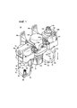
Фиг. 1 - внешнее перспективное изображение блока с рабочим веществом под давлением, в котором используется конструкция кожуха, в соответствии с первым примером осуществления настоящего изобретения;FIG. 1 is an external perspective view of a pressurized working unit in which a housing structure is used in accordance with a first embodiment of the present invention;
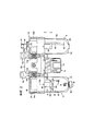
Фиг. 2 - вид спереди блока с рабочим веществом под давлением, показанного на Фиг. 1;FIG. 2 is a front view of the pressure medium unit shown in FIG. one;
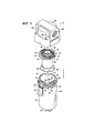
Фиг. 3 - покомпонентное перспективное изображение в разрезе фильтра, который составляет часть блока с рабочим веществом под давлением по Фиг. 1;FIG. 3 is an exploded perspective view in section of a filter that forms part of a block with a working substance under pressure according to FIG. one;
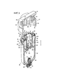
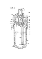
Фиг. 4 - изображение полного поперечного сечения фильтра, показанного на Фиг. 3;FIG. 4 is a full cross-sectional view of the filter shown in FIG. 3;
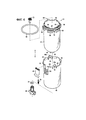
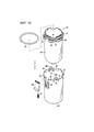
Фиг. 5 - покомпонентное перспективное изображение фильтра, который составляет часть блока с рабочим веществом под давлением по Фиг. 1;FIG. 5 is an exploded perspective view of a filter that forms part of a block with a working substance under pressure according to FIG. one;
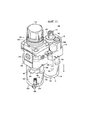
Фиг. 6 - покомпонентное перспективное изображение блока кожухов, который составляет часть фильтра по Фиг. 5;FIG. 6 is an exploded perspective view of a housing unit that forms part of the filter of FIG. 5;
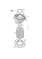
Фиг. 7 - покомпонентное перспективное изображение фильтровального блока, который составляет часть фильтра по Фиг. 5;FIG. 7 is an exploded perspective view of a filter unit that forms part of the filter of FIG. 5;
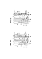
Фиг. 8А - изображение поперечного сечения, взятого по линии VIIIA-VIIIA по фиг. 2;FIG. 8A is a cross-sectional view taken along line VIIIA-VIIIA of FIG. 2;
Фиг. 8В - изображение поперечного сечения, показывающее состояние, в котором кнопка разъединения из Фиг. 8А опущена и регулируемое состояние вращения между первым корпусом и блоком кожухов прекращается;FIG. 8B is a cross-sectional view showing a state in which the disconnect button of FIG. 8A is omitted and the adjustable state of rotation between the first housing and the housing unit is terminated;
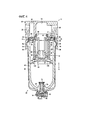
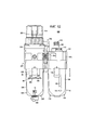
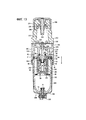
Фиг. 9 - изображение полного поперечного сечения лубрикатора, который составляет часть блока с рабочим веществом под давлением по Фиг. 1;FIG. 9 is a full cross-sectional view of a lubricator that forms part of a block with a working substance under pressure according to FIG. one;
Фиг. 10 - покомпонентное перспективное изображение блока кожухов, который составляет часть лубрикатора по Фиг. 1;FIG. 10 is an exploded perspective view of a housing unit that forms part of the lubricator of FIG. one;
Фиг. 11 - внешнее перспективное изображение блока с рабочим веществом под давлением, в котором используется конструкция кожуха, в соответствии со вторым примером осуществления настоящего изобретения;FIG. 11 is an external perspective view of a pressurized working unit in which a housing structure is used in accordance with a second embodiment of the present invention;
Фиг. 12 - вид спереди блока с рабочим веществом под давлением, показанного на Фиг. 11; иFIG. 12 is a front view of the pressure medium unit shown in FIG. eleven; and
Фиг. 13 - изображение полного поперечного сечения фильтра-регулятора, который составляет часть блока с рабочим веществом под давлением по Фиг. 12.FIG. 13 is a full cross-sectional view of a filter regulator that forms part of a block with a working substance under pressure according to FIG. 12.
Описание примеров осуществленияDescription of Examples
На Фиг. 1 ссылочной цифрой 10 показан блок с рабочим веществом под давлением, содержащий устройства с рабочим веществом под давлением, в которых используется конструкция кожуха, в соответствии с первым примером осуществления настоящего изобретения.In FIG. 1,
Как показывается на Фиг. 1 и Фиг. 2, блок с рабочим веществом под давлением 10 состоит из фильтра 12, которое удаляет пыль, инородные частицы и прочие примеси, содержащиеся в рабочем веществе, регулятора 14, который понижает давление рабочего вещества, лубрикатора 16, который смешивает жидкую смазку с рабочим веществом под давлением, и соединителей 18а, 18b, которые соединяют между собой в одно целое фильтр 12, регулятор 14 и лубрикатор 16.As shown in FIG. 1 and FIG. 2, the block with the working substance under
Вышеупомянутые фильтр 12, регулятор 14 и лубрикатор 16 функционируют как устройства с рабочим веществом под давлением, внутрь которых подается рабочее вещество. Регулятор 14 расположен между фильтром 12 и лубрикатором 16.The
Как показывается на Фиг. 1 - Фиг. 7, фильтр 12 содержит первый корпус (корпус) 20, блок кожухов (кожух) 22, подсоединенный к нижней части первого корпуса 20, и фильтровальный блок 24, который установлен внутри блока кожухов 22.As shown in FIG. 1 - FIG. 7, the
По бокам, то есть на соответствующих сторонах, первого корпуса 20, расположены первый и второй каналы (каналы) 26, 28 для подачи и отвода рабочего вещества под давлением, при этом первый и второй каналы 26, 28 открыты приблизительно в горизонтальном направлении (см. Фиг. 4). Первый канал 26 подсоединен к не показанному трубопроводу, и через такой трубопровод подается рабочее вещество под давлением. Первый канал 26 сообщается с первым соединительным проходом 30, который тянется в аксиальном направлении (в направлении по стрелкам А и В) через внутреннюю область первого корпуса 20.On the sides, that is, on the respective sides of the
Из второго канала 28 рабочее вещество под давлением, подаваемое через первый канал 26, выпускается в регулятор 14, описанный позднее. Второй канал 28 сообщается со вторым соединительным проходом 32, который тянется в аксиальном направлении (в направлении по стрелкам А и В) через внутреннюю область первого корпуса 20.From the
Кроме того, на боковых поверхностях первого корпуса 20 имеются пары соединительных выступов 34а, 34b, каждая из которых расположена напротив друг друга на внешних краях торцевых поверхностей, на которых находятся первый и второй каналы 26, 28.In addition, on the lateral surfaces of the
В нижней части первого корпуса 20 открыт монтажный проем 36, в который вставляется блок кожухов 22. Первый соединительный проход 30 сообщается с внешней периферической стороной монтажного проема 36, который в поперечном сечении имеет приблизительно круглую форму, в то время как второй соединительный проход 32 сообщается с центральной частью монтажного проема 36.In the lower part of the
Как показывается на Фиг. 3 и Фиг. 4, на внутренней периферической поверхности монтажного проема 36 образовано несколько опорных элементов (вторые соединительные элементы) 38, которые выступают внутрь в радиальном направлении. С опорными элементами 38 входят в зацепление выступы (первые соединительные элементы) 58 внутреннего кожуха (вторая часть кожуха) 42, который является частью блока кожухов 22, и фиксирующие перегородки (первые соединительные элементы) 56 внешнего кожуха (первая часть кожуха) 40. Опорные элементы 38 разделены между собой равными интервалами в направлении по периферической окружности монтажного проема 36.As shown in FIG. 3 and FIG. 4, several support elements (second connecting elements) 38 are formed on the inner peripheral surface of the
Блок кожухов 22 содержит внешний кожух 40, выполненный в виде цилиндра с дном, и внутренний кожух 42, который вставляется внутрь внешнего кожуха 40, кнопку разъединения (управляющую кнопку) 44, расположенную с возможностью смещения относительно внешнего кожуха 40, и дренажный кран 46, расположенный на нижних частях внешнего кожуха 40 и внутреннего кожуха 42.The block of
Внешний кожух 40 выполнен, в основном, с постоянным диаметром и с заранее заданной длиной в аксиальном направлении (в направлении по стрелкам А и В) из светопроницаемого прозрачного полимерного материала (акрил, поликарбонат и проч.). Нижняя часть внешнего кожуха 40 выполнена в форме полусферы, а нижний торец внешнего кожуха 40 открыт кверху.The
На верхней части внешнего кожуха 40 образована пара соединительных язычков 48а, 48b (см. Фиг. 6), которые выступают кверху (в направлении по стрелке А) в аксиальном направлении, а на участке, находящемся между одним из соединительных язычков 48а и другим из соединительных язычков 48b, образовано отверстие под кнопку 50, в котором устанавливается описанная позднее кнопка разъединения 44. Соединительные язычки 48а, 48b могут деформироваться в радиальных направлениях внешнего кожуха 40. Приблизительно в центральных частях соединительных язычков 48а, 48b расположены отверстия 54, с которыми могут зацепляться соответствующие выступы 52 внутреннего кожуха 42. Отверстия 54 имеют приблизительно прямоугольную форму.On the upper part of the
Кроме того, в аксиальном направлении (в направлении по стрелке В), книзу от верхнего края внешнего кожуха 40 образовано отверстие под кнопку 50, которое выполнено приблизительно в виде прямоугольного выреза.In addition, in the axial direction (in the direction of arrow B), an opening for the
Далее, на верхней части внешнего кожуха 40 образовано несколько фиксирующих перегородок 56, которые постепенно расширяются по диаметру наружу в радиальном направлении. Фиксирующие перегородки 56 разделены между собой, в основном, равными интервалами и проходят в направлении по периферической окружности внешнего кожуха 40. Так что в случае, когда внутренний кожух 42 устанавливается внутри внешнего кожуха 40, выступы 58 будут удерживаться фиксирующими перегородками 56.Further, on the upper part of the
С другой стороны, в основном, в центральной части по оси, на нижней части внешнего кожуха 40 образовано отверстие под бобышку 60, в которое вставляется дренажная бобышка 68 (описанная позднее) внутреннего кожуха 42.On the other hand, basically, in the central part along the axis, on the lower part of the
Внутренний кожух 42, аналогично внешнему кожуху 40, является, в основном, постоянным по диаметру и выполнен, например, из светопроницаемого прозрачного полимерного материала (поликарбоната и т.п.) и тянется на заранее заданную длину в аксиальном направлении (в направлении по стрелкам А и В). Нижняя часть внутреннего кожуха 42 имеет полусферическую форму, а его верхний торец открыт кверху. Внешний диаметр внутреннего кожуха 42 равен или делается несколько меньше, чем внутренний диаметр внешнего кожуха 40 (см. Фиг. 4). Кроме того, внутренний кожух 42 устанавливается внутри внешнего кожуха 40, так что внутренний кожух 42 не подвержен внешней среде внешнего кожуха 40.The
Далее, на верхней части внутреннего кожуха 42 образовано несколько выступов 58, которые направлены в радиальном направлении наружу от его внешней периферической поверхности, при этом выступы 58 расположены, в основном, через равные интервалы в направлении по периферической окружности внутреннего кожуха 42. Число выступов 58 и фиксирующих перегородок 56 составляет ту же самую величину, что и число опорных элементов 38 первого корпуса 20, а интервалы между смежными выступами 58 и фиксирующими перегородками 56 задаются теми же самыми, что и интервалы между смежными опорными элементами 38.Further, on the upper part of the
На нижних кромках выступов 58 образованы скошенные поверхности, которые наклонены кверху, в то время как верхние поверхности выступов 58 представляют собой плоскости, которые проходят, в основном, горизонтально по верхним поверхностям выступов 58. Кроме того, когда внутренний кожух 42 устанавливается внутри внешнего кожуха 40, то наклонные поверхности выступов примыкают к соответствующим фиксирующим перегородкам 56 и соединяются с ними.On the lower edges of the
Кроме того, между двумя смежными выступами 58 находится пара выступов 52, которые выходят наружу на заранее заданную высоту относительно внешней периферической поверхности внутреннего кожуха 42. Так что в случае, когда внутренний кожух 42 монтируется внутри внешнего кожуха 40, то выступы 52, которые имеют, в основном, прямоугольную форму в поперечном сечении, зацепляются с отверстиями 54 соединительных язычков 48а, 48b. По этой причине, внешний кожух 40 и внутренний кожух 42 прочно соединяются между собой парой соединительных язычков 48а, 48b.In addition, between the two
Далее, на верхней части внутреннего кожуха 42 образована кольцевая стенка 62, которая уменьшается по диаметру внутрь в радиальном направлении относительно внешней периферической поверхности внутреннего кожуха 42. На кольцевой стенке 62 расположено несколько зацепок 64, которые выступают наружу от ее верхней части, и, наряду с этим, на внешней периферической стороне кольцевой стенки 62 установлено первое уплотнительное кольцо 66, выполненное из эластичного материала. Зацепки 64 расположены через равные интервалы между собой в направлении по периферической окружности внутреннего кожуха 42, при этом верхние концы зацепок 64 выступают наружу в радиальных направлениях. Иными словами, верхние концы зацепок 64 имеют L-образную форму в поперечном сечении и выступают радиально наружу.Further, on the upper part of the
Когда фильтровальный блок 24 устанавливается внутри блока кожухов 22, содержащего внутренний кожух 42, то зацепками 64 фиксируется дефлектор 82 (описанный позднее), который составляет часть фильтровального блока 24,When the
С другой стороны, на нижней части внутреннего кожуха 42 образована дренажная бобышка 68, которая выступает в аксиальном направлении (в направлении по стрелкам А и В), в основном, в центральной части по оси. Внутри дренажной бобышки 68 образовано дренажное отверстие 70, в которое вставляется дренажный кран 46.On the other hand, a
Кроме того, в случае, когда внутренний кожух 42 устанавливается во внешнем кожухе 40, то после того как дренажная бобышка 68 внутреннего кожуха 42 будет введена внутрь отверстия под бобышку 60 внешнего кожуха 40, в дренажное отверстие 70 вводится дренажный кран 46 (например, слегка запрессовывается), и закрепляется изнутри во внутреннем кожухе 42 фиксирующей заглушкой 72.In addition, in the case where the
На внешней периферической поверхности дренажного крана 46 посредством кольцевой канавки устанавливается второе уплотнительное кольцо 74, выполненное из эластичного материала, так что за счет ввода второго уплотнительного кольца 74 в дренажное отверстие 70 и его примыкания к внутренней периферической поверхности дренажного отверстия 70 предотвращается утечка рабочего вещества под давлением между дренажным краном 46 и дренажным отверстием 70.A second O-
Кнопка разъединения 44 выполнена из бруска, имеющего L-образную форму в поперечном сечении, который устанавливается в отверстие под кнопку 50 таким образом, что его выступающая часть располагается по внешней стороне внешнего кожуха 40 и нижней стороне кнопки разъединения 44 (в направлении по стрелке В). Кнопка разъединения 44 устанавливается с возможностью смещения в направлениях вверх и вниз (направления по стрелкам А и В) вдоль отверстия под кнопку 50, при этом между кнопкой разъединения 44 и нижней торцевой поверхностью отверстия под кнопку 50 расположена пружина 76. Таким образом, кнопка разъединения 44 в нормальном состоянии смещена кверху по внешнему кожуху 40 (в направлении по стрелке А).The
Кроме того, если блок кожухов 22 устанавливается в монтажный проем 36 первого корпуса 20, то верхний конец кнопки разъединения 44 вводится в фасонную выемку 78 (см. Фиг. 8А), которая образована в монтажном проеме 36 первого корпуса 20. Благодаря этому, регулируется смещение блока кожухов 22 в направлении вращения относительно первого корпуса 20.In addition, if the
Иными словами, кнопка разъединения 44 функционирует как стопорный элемент для регулировки вращательного смещения блока кожухов 22 в состоянии, в котором блок кожухов 22 соединяется с первым корпусом 20.In other words, the
Как показывается на Фиг. 3 - Фиг. 5 и Фиг. 7, фильтровальный блок 24 содержит фильтровальный элемент 80 цилиндрической формы, дефлектор 82, который фиксирует фильтровальный элемент 80, и разделительную перегородку 84, которая установлена на конце дефлектора 82. Фильтровальный элемент 80 выполнен в виде цилиндра, на котором намотаны волокна, например, полипропилена, полиэтилена и т.п., имеющие заранее заданную толщину в радиальном направлении.As shown in FIG. 3 - FIG. 5 and FIG. 7, the
Дефлектор 82 содержит основной корпус 86 дискообразной формы и фиксирующий элемент 88, образованный на нижней части основного корпуса 86, который позволяет крепить разделительную перегородку 84. Через центральную часть основного корпуса 86 проходит сквозное отверстие 90, а по внешней периферической стороне сквозного отверстия 90 проходит несколько пластин 91. Пластины 91 разделены между собой равными интервалами, расположены по периферической окружности дефлектора 82, и выполнены такими, что они наклонены под заранее заданным углом относительно аксиального направления дефлектора 82.The
Далее, на внешней периферической стороне сквозного отверстия 90 в основном корпусе 86 установлено третье уплотнительное кольцо 92, выполненное из эластичного материала. Третье уплотнительное кольцо 92 примыкает к внутренней периферической поверхности второго соединительного прохода 32 в том состоянии, когда фильтровальный блок 24 устанавливается в первом корпусе 20 вместе с блоком кожухов 22. Благодаря этому, предотвращается утечка рабочего вещества под давлением между фильтровальным блоком 24 и вторым соединительным проходом 32.Further, on the outer peripheral side of the through
Далее, на основном корпусе 86 образовано несколько (например, четыре) направляющих перегородок 94, которые выступают книзу (в направлении по стрелке В) на внешней торцевой части, которая определяет внешнюю периферическую сторону пластин 91. Направляющие перегородки 94 разделены между собой равными интервалами, расположены по периферической окружности основного корпуса 86, и отстоят на заранее заданное расстояние в радиальном направлении от внешней торцевой части. Далее, нижние торцы направляющих перегородок 94 имеют L-образную форму в поперечном сечении и свернуты внутрь в радиальном направлении.Further, on the
Кроме того, когда фильтровальный блок 24 устанавливается в блоке кожухов 22, то зацепки 64 внутреннего кожуха 42 вводятся во внутренние периферические стороны направляющих перегородок 94, тем самым нижние торцы направляющих перегородок 94 и верхние торцы зацепок 64 накладываются друг на друга в радиальном направлении (см. Фиг. 4). Благодаря этому, регулируется смещение в аксиальном направлении (в направлении по стрелкам А и В) внутреннего кожуха 42 и фильтровального блока 24, содержащего дефлектор 82. Следовательно, фильтровальный блок 24 подсоединяется, будучи установленным внутри блока кожухов 22.In addition, when the
С другой стороны, на нижней поверхности основного корпуса 86 образована канавка под фильтр 96 в форме кольца, в которую вводится верхний конец фильтровального элемента 80.On the other hand, on the lower surface of the
Фиксирующий элемент 88 имеет цилиндрическую форму и подсоединяется к основному корпусу 86, и вместе с этим располагается на заранее заданном расстоянии от основного корпуса 86 в аксиальном направлении (в направлении по стрелке В). Кроме того, из внешней периферической стороны фиксирующего элемента 88 выступает пара штырьков 98, и при введении штырьков 98 в канавки 100 разделительной перегородки 84, которая описана позднее, разделительная перегородка 84 соединяется с фиксирующим элементом 88. Кроме того, по внешней периферической стороне фиксирующего элемента 88 вводится фильтровальный элемент 80 цилиндрической формы.The locking
Разделительная перегородка 84 содержит основание 102 в форме диска, соединитель 104, образованный на верхней части основания 102 и подсоединенный к фиксирующему элементу 88 дефлектора 82, и юбку 106, образованную на нижней части основания 102. Основание 102 имеет, в основном, плоскую форму, а нижняя торцевая поверхность фильтровального элемента 80 примыкает к верхней поверхности основания 102 и фиксируется ей. Соединитель 104 имеет коническую форму в поперечном сечении, постепенно сходящуюся на конус в направлении кверху. Вдоль поверхности стенки соединителя 104, в направлении по его периферической окружности, проходит пара канавок 100.The
Кроме того, когда фиксирующий элемент 88 дефлектора 82 вводится через фильтровальный элемент 80, то после того, как фиксирующий элемент 88 будет введен внутрь соединителя 104, а штырьки 98 будут введены в соответствующие канавки 100, фиксирующий элемент 88 и разделительная перегородка 84 поворачиваются по окружности на заранее заданный угол во взаимно противоположных направлениях. Следовательно, штырьки 98 перемещаются к концам канавок 100 и оказываются сцепленными с ними. В результате, регулируется относительное смещение в аксиальном направлении (в направлении по стрелкам А и В) между дефлектором 82 и разделительной перегородкой 84, и разделительная перегородка 84 соединяется с фиксирующим элементом 88, устанавливаясь в состояние, в котором фильтровальный элемент 80 закрепляется между дефлектором 82 и разделительной перегородкой 84.In addition, when the locking
Как показывается на Фиг. 1 и Фиг. 2, регулятор 14 содержит второй корпус 108, управляющую ручку 110, установленную с возможностью вращения на нижней части второго корпуса 108, и регулировочный механизм (не показан), который обеспечивает регулировку давления рабочего вещества при манипулировании управляющей ручкой 110. По бокам, то есть на соответствующих сторонах, второго корпуса 108, образована пара каналов (не показаны) для подачи и отвода рабочего вещества под давлением. Один из каналов подсоединен и сообщается со вторым каналом 28 фильтра 12, к которому подается рабочее вещество под давлением от фильтра 12, а другой из каналов подсоединен и сообщается с третьим каналом 122 (описан позднее) лубрикатора 16, через который выпускается рабочее вещество под давлением.As shown in FIG. 1 and FIG. 2, the
Далее, на боковых поверхностях второго корпуса 108, на взаимно противоположных направлениях к внешним краям торцевых поверхностей, на которых образована пара каналов, расположены пары соединительных выступов 112а, 112b. В состоянии, при котором соединительные выступы 112а торцевой поверхности, которая соединяется со вторым каналом 28 фильтра 12, примыкают к соединительным выступам 34b смежного фильтра 12, соединительные выступы 34b, 112а соединяются между собой установкой соединителя 18а так, что он покрывает внешние стороны соединительных выступов 34b, 112а. В это время второй канал 28 фильтра 12 и один из каналов регулятора 14 соединяются и сообщаются между собой.Further, on the lateral surfaces of the
Регулятор 14 имеет внутри механизм регулировки давления. Механизм регулировки давления управляется вращением ручки 110 так, что после того как давление рабочего вещества, поступающего от одного канала, будет настроено до желаемого давления, рабочее вещество под давлением выбрасывается из другого канала и подается на лубрикатор 16.The
Лубрикатор 16 применяется для того, чтобы жидкая смазка вводилась по каплям в рабочее вещество под давлением. Лубрикатор, используя поток рабочего вещества под давлением, подает жидкую смазку на скользящие части в других устройствах с рабочим веществом под давлением. Как показывается на Фиг. 1, Фиг. 2, Фиг. 9 и Фиг. 10, лубрикатор 16 содержит третий корпус 114, блок кожухов 116, подсоединенный к нижней части третьего корпуса 114, капельницу 118, которая введена внутрь третьего корпуса 114, и держатель 120 для крепления капельницы 118 внутри третьего корпуса 114.
По бокам, то есть на соответствующих сторонах третьего корпуса 114, расположены третий и четвертый каналы 122, 124 для подвода и выпуска рабочего вещества под давлением. Третий канал 122 и четвертый канал 124 сообщаются между собой через третий соединительный проход 126. Третий канал 122 подсоединен к другому каналу в регуляторе 14, который расположен смежно с ним, а четвертый канал 124 подсоединен к не показанному трубопроводу.On the sides, that is, on the respective sides of the
Далее, на боковых поверхностях третьего корпуса 114 расположены пары соединительных выступов 128а, 128b, находящиеся на взаимно противоположных друг к другу внешних краях торцевых поверхностей, на которых находятся третий и четвертый каналы 122, 124. В состоянии, когда соединительные выступы 128а на торцевой поверхности лубрикатора 16, обращенной к регулятору 14, примыкают к соединительным выступам 112b регулятора 14, соединительные выступы 112b, 128а соединяются между собой установкой соединителя 18b так, что он покрывает внешние стороны соединительных выступов 112b, 128а. В это время, третий канал 122 лубрикатора 16 соединяется и сообщается с другим каналом на регуляторе 14.Further, on the lateral surfaces of the
Кроме того, в нижней части третьего корпуса 114 открыт монтажный проем 130, в которое вставляется блок кожухов 116. Как показывается на Фиг. 9, на внутренней периферической поверхности монтажного проема 130 образовано несколько опорных элементов 132, которые выступают внутрь в радиальном направлении. Выступы 58 внутреннего кожуха (вторая часть кожуха) 138 и фиксирующие перегородки 56 внешнего кожуха (первая часть кожуха) 136 сцепляются с опорными элементами 132. Блок кожухов 116 содержит внутренний кожух 138 и внешний кожух 136. Опорные элементы 132 расположены так, что они разделены между собой равными интервалами в направлении периферической окружности монтажного проема 130.In addition, a mounting
Далее, в монтажном проеме 130 образован вспомогательный проход 134, который простирается в сторону третьего канала 122 (в направлении по стрелке А). Часть рабочего вещества под давлением, поступающего в третий канал 122, подается через вспомогательный проход 134 внутрь блока кожухов 116, который устанавливается в монтажном проеме 130.Further, an
Блок кожухов 116 содержит внешний кожух 136, выполненный в виде цилиндра с дном, внутренний кожух 138, вставленный внутрь внешнего кожуха 136, и кнопку разъединения 140, которая может смещаться относительно внешнего кожуха 136. Внутренний кожух 138 устанавливается внутри внешнего кожуха 136 так, что он не выступает наружу за внешний кожух 136. Конструкция блока кожухов 116 приблизительно такая же, как и конструкция блока кожухов 22 фильтра 12, описанного выше. Соответственно, к его одинаковым составным элементам применяются одинаковые ссылочные цифры, и детальные описания особенностей таких элементов опускаются.
Внешний кожух 136 имеет, в основном, постоянный диаметр и заранее заданную длину в аксиальном направлении и выполнен из светопроницаемого прозрачного полимерного материала (акрил, поликарбонат и т.п.). Нижняя часть внешнего кожуха 136 имеет полусферическую форму, а верхний торец внешнего кожуха 136 открыт кверху. На верхней части внешнего кожуха 136 образована пара соединительных язычков 48а, 48b, которые выступают кверху (в направлении по стрелке А) в аксиальном направлении, а в промежутке, находящимся между одним из соединительных язычков 48а и другим из соединительных язычков 48b, расположено отверстие под кнопку 50, в которое устанавливается кнопка разъединения 140, описанная позднее.The
Кроме того, на верхней части внешнего кожуха 136 образовано несколько фиксирующих перегородок 56, которые постепенно расширяются по диаметру наружу в радиальном направлении. Фиксирующие перегородки 56 разделены между собой, в основном, равными интервалами, проходя в направлении периферической окружности внешнего кожуха 136, так что выступы 58 могут быть зафиксированы фиксирующими перегородками 56, когда внутренний кожух 138 будет установлен внутри внешнего кожуха 136.In addition, on the upper part of the
Внутренний кожух 138, аналогично внешнему кожуху 136, выполнен, в основном, с постоянным диаметром, например, из светопроницаемого прозрачного полимерного материала (поликарбонат или т.п.) и проходит в аксиальном направлении на заранее заданную длину. Нижняя часть внутреннего кожуха 138 имеет полусферическую форму, а его верхний торец открыт кверху. Внутренний кожух 138 заполняется жидкой смазкой через пробку заливки смазки 142 (см. Фиг. 1 и Фиг. 2), которая находится на третьем корпусе 114.The
Далее, на верхней части внутреннего кожуха 138 образовано несколько выступов 58, которые направлены радиально наружу от его внешней периферической поверхности, при этом выступы 58 расположены между собой через равные, в основном, интервалы и проходят в направлении периферической окружности внутреннего кожуха 138. Когда внутренний кожух 138 устанавливаются внутри внешнего кожуха 136, то наклонные поверхности выступов 58 примыкают к фиксирующим перегородкам 56 и соответственно закрепляются ими.Further, on the upper part of the
Далее, между двумя смежными выступами 58 находится пара выступов 52, которые направлены наружу на заранее заданную высоту относительно внешней периферической поверхности внутреннего кожуха 138. Когда внутренний кожух 138 устанавливается внутри внешнего кожуха 136, то выступы 52, которые в поперечном сечении имеют, в основном, прямоугольную форму, зацепляются с отверстиями 54 соединительных язычков 48а, 48b. По этой причине, внешний кожух 136 и внутренний кожух 138 прочно соединяются между собой.Further, between the two
Кроме того, на верхней части внутреннего кожуха 138 образована кольцевая стенка 62, которая уменьшается по диаметру внутрь в радиальном направлении относительно внешней периферической поверхности внутреннего кожуха 138. На кольцевой стенке 62 расположено несколько зацепок 64, которые выступают наружу от ее верхней части, и вместе с этим, по внешней периферической стороне кольцевой стенки 62 установлено первое уплотнительное кольцо 66, выполненное их эластичного материала.In addition, an
Кнопка разъединения 140 выполнена из бруска, имеющего L-образную форму в поперечном сечении, который устанавливается в отверстие под кнопку 50 таким образом, что его выступающая часть располагается по внешней стороне внешнего кожуха 136 и нижней стороне кнопки разъединения 140 (в направлении по стрелке В). Кнопка разъединения 140 устанавливается с возможностью смещения в направлениях вверх и вниз (в направлении по стрелкам А и В) вдоль отверстия под кнопку 50, при этом между кнопкой разъединения 140 и нижней торцевой поверхностью отверстия под кнопку 50 расположена пружина 76. Таким образом, кнопка разъединения 140 в нормальном состоянии смещена кверху по внешнему кожуху 136 (в направлении по стрелке А).The
Кроме того, если блок кожухов 116 устанавливается в монтажный проем 130 третьего корпуса 114, то верхний конец кнопки разъединения 140 вводится в фасонную выемку 78, которая образована в монтажном проеме 130 третьего корпуса 114. Благодаря этому, регулируется смещение блока кожухов 116 в направлении вращения относительно третьего корпуса 114. Иными словами, кнопка разъединения 140 функционирует как стопорный элемент для регулировки вращательного смещения блока кожухов 116 в состоянии, в котором блок кожухов 116 соединяется с третьим корпусом 114.In addition, if the
Как показывается на Фиг. 9, капельница 118 содержит внутренний элемент 144, который вставляется внутрь третьего корпуса 114, и капельной втулки 146, которая расположена на верхней части внутреннего элемента 144. Внутренний элемент 144 устанавливается так, что он проходит через третий соединительный проход 126.As shown in FIG. 9, the
Внутренний элемент 144 содержит четвертый соединительный проход 148, который проходит через него горизонтально. Четвертый соединительный проход 148 расположен по прямой линии вместе с третьим соединительным проходом 126. Более конкретно, рабочее вещество под давлением, которое поступает на третий канал 122, проходит через третий и четвертый соединительные проходы 126, 148 и протекает к четвертому каналу Далее, в четвертом соединительном проходе 148 устанавливается демпфер 150, выполненный из эластичного материала и проходящий вертикально вверх, перпендикулярно к направлению прохождения четвертного соединительного прохода 148. Демпфер 150 устанавливается так, что он может быть наклонен под заранее заданным углом в сторону четвертого канала 124 в соответствии с величиной давления потока рабочего вещества, которое поступает от третьего канала 122.The
Над четвертым соединительным проходом 148 во внутреннем элементе 144 образован резервуар 152, через который от внутреннего кожуха 138 подается жидкая смазка. Резервуар 152 сообщается со смазочным проходом 154, которая проходит книзу, и через этот смазочный проход 154 подается жидкая смазка. В центральной, в основном, части резервуара 152 открыто книзу капельное отверстие 156, которое сообщается с четвертым соединительным проходом 148. Смазочный проход 154 перпендикулярен к четвертому соединительному проходу 148, простирается через него, при этом он отделен от четвертого соединительного прохода 148, и сообщается с каналом подачи смазки 158, который образован в держателе 120.Above the fourth connecting
Держатель 120 установлен на нижней части внутреннего элемента 144, который образует капельницу 118, и фиксирует часть демпфера 150, находящуюся между внутренним элементом 144 и держателем 120. Держатель 120 содержит канал подачи смазки 158, который сообщается со смазочным проходом 154. Канал подачи смазки 158 выступает книзу (в направлении по стрелке В) и расположен во внутреннем кожухе 138. К каналу подачи смазки 158 подсоединена направляющая трубка смазки 160.A
Направляющая трубка смазки 160 имеет заранее заданную длину в аксиальном направлении (в направлении по стрелкам А и В), и в состоянии, когда она подсоединена к каналу подачи смазки 158, проходит вблизи от нижней части внутреннего кожуха 138. Далее, на нижнем торце направляющей трубки смазки 160 расположен фильтр очистки 162 для удаления инородных веществ и других примесей, которые могут содержаться в жидкой смазке.The
Кроме того, жидкая смазка, которая заполняет внутренний кожух 138, после прохождения через направляющую трубку смазки 160 и протекания в сторону держателя 120, проходит через смазочный проход 154 и поступает в резервуар 152. Из резервуара 152 жидкая смазка проходит через капельное отверстие 156 и закапывается внутрь четвертого соединительного прохода 148. В результате, с рабочим веществом под давлением, которое проходит через четвертый соединительный проход 148, смешивается заранее заданной количество жидкой смазки. В канале подачи смазки 158 расположен обратный клапан 164 для предотвращения противотока жидкой смазки в сторону внутреннего кожуха 138 из смазочного прохода 154.In addition, the liquid lubricant that fills the
Блок с рабочим веществом под давлением 10, в котором используется конструкция кожуха в соответствии с первым примером осуществления настоящего изобретения, сконструирован, в основном, как описано выше. Затем будут даны объяснения, касающиеся сборки фильтра 12 и лубрикатора 16. Сначала будет дано объяснение сборки фильтра 12 со ссылками на Фиг. 4 - Фиг. 6. В последующих объяснениях принимается, что фильтровальный блок 24 находится в предварительно собранном состоянии, т.е., когда фильтровальный элемент 80, дефлектор 82 и направляющая перегородка 84 уже смонтированы между собой (см. Фиг. 5).The pressurized working
Сначала собирается блок кожухов 22. В этом случае при состоянии, показанном на Фиг.6, внутренний кожух 42 вставляется снаружи внутрь открытого внешнего кожуха 40, и их нижние части устанавливаются вблизи друг от друга, тем самым дренажная бобышка 68 вводится в отверстие под бобышку 60. В то же самое время, соединительные язычки 48а, 48b внешнего кожуха 40 устанавливаются напротив выступов 52 внутреннего кожуха 42, и выступы 52 вводятся в отверстия 54. Следовательно, отверстия 54 соединительных язычков 48а, 48b и выступы 52 приходят в зацепление, тем самым внешний кожух 40 и внутренний кожух 42 соединяются между собой так, что внутренний кожух 42 устанавливается внутри внешнего кожуха 40.First, the block of
В этой ситуации, внешний кожух 40 и внутренний кожух 42 соединяются так, что регулируется относительное смещение как в аксиальном направлении (в направлении по стрелкам А и В), так и в направлении по периферической окружности, внутренний кожух 42 покрывается внешним кожухом 40, и внутренний кожух 42 устанавливается так, что он не подвергается воздействию внешней среды внешнего корпуса 40.In this situation, the
Далее, фиксирующие перегородки 56 внешнего кожуха 40 примыкают соответственно к нижним торцевым поверхностям на выступах 58 внутреннего кожуха 42 (см. Фиг. 4).Further, the locking
Кроме того, после того, как дренажный кран 46 будет установлен ниже отверстия под бобышку 60 внешнего кожуха 40, дренажный кран 46 фиксируется фиксирующей заглушкой 72, и сборка блока кожухов 22 завершается установкой первого уплотнительного кольца 66 на внешнюю периферическую сторону кольцевой стенки 62 внутреннего кожуха 42 (см. Фиг. 3 и Фиг. 5).In addition, after the
Далее, при состоянии, показанном на Фиг. 5, внутрь блока кожухов 22 вводится фильтровальный блок 24 так, что основной корпус 86 дефлектора 82 располагается кверху, а зацепки 64 внутреннего кожуха 42 располагаются в положениях между направляющими перегородками 94 основного корпуса 86. Кроме того, поворотом фильтровального блока 24 на заранее заданный угол вокруг его оси относительно блока кожухов 22, зацепки 64 устанавливаются напротив направляющих перегородок 94 и перемещаются к внутренним периферическим сторонам направляющих перегородок 94. Более конкретно, несколько зацепок 64 устанавливаются в такое состояние, в котором они соответственно покрываются направляющими перегородками 94.Further, in the state shown in FIG. 5, a
Следовательно, верхние концы зацепок 64 устанавливаются в такое состояние, что они перекрещиваются в радиальном направлении с нижними концами направляющих перегородок 94, тем самым регулируется смещение в аксиальном направлении (в направлении по стрелкам А и В) между внутренним кожухом 42 и фильтровальным блоком 24, содержащим дефлектор 82. В результате, фильтровальный блок 24 и блок кожухов 22 взаимно соединяются между собой, при этом фильтровальный блок 24 устанавливается внутри блока кожухов 22.Therefore, the upper ends of the
В заключение, блок кожухов 22, открытая часть которого направлена кверху и в котором смонтирован фильтровальный блок 24, вставляется в монтажный проем 36 первого корпуса 20, и блок кожухов 22 поворачивается на заранее заданный угол вокруг своей оси относительно первого корпуса 20. В результате, выступы 58 и фиксирующие перегородки 56 совмещаются в аксиальном направлении (в направлении по стрелкам А и В) с опорными элементами 38, а выступы 58 и фиксирующие перегородки 56 входят в зацепление с опорными элементами 38. В это же время, фиксирующие перегородки 56, которые примыкают к нижним частям выступов 58, начинают также примыкать к опорным элементам 38.In conclusion, the block of
Далее, в то же самое время, как показывается на Фиг. 8А, кнопка разъединения 44 перемещается кверху (в направлении по стрелке А) силой упругости пружины 76 и вводится в фасонную выемку 78 монтажного проема 36. По этой причине, блок кожухов 22 в состоянии, при котором он введен в монтажный проем 36 первого корпуса 20, фиксируется опорными элементами 38 и предотвращается его выпадение книзу (в направлении по стрелке В), при этом перемещение блока кожухов 22 во вращательном направлении (т.е. в направлении по стрелке С на Фиг. 3) регулируется кнопкой разъединения 44. Более конкретно, поскольку вращение блока кожухов 22 относительно первого корпуса 20 регулируется кнопкой разъединения 44, то состояние соединения с опорными элементами 38 не может быть нарушено.Further, at the same time as shown in FIG. 8A, the
По этой причине, блок кожухов 22, в котором находится фильтровальный блок 24, устанавливается так, что он подсоединяется к нижней части первого корпуса 20, тем самым сборка фильтра 12 завершается (см. Фиг. 4). В это же время, как показывается на Фиг. 4, первый соединительный проход 30 и пластины 91 дефлектора 82 устанавливаются напротив друг друга и сообщаются между собой, а второй соединительный проход 32 сообщается со сквозным отверстием 90. Далее, первое уплотнительное кольцо 66 примыкает к внутренней периферической поверхности монтажного проема 36, а третье уплотнительное кольцо 92 примыкает к внутренней периферической поверхности второго соединительного прохода 32.For this reason, the
Как показывается на Фиг. 8В, если блок кожухов 22 должен быть вынут из первого корпуса 20, то кнопка разъединения 44 отжимается книзу, противодействуя силе упругости пружины 76, тем самым кнопка разъединения 44 отсоединяется из фасонной выемки 78. По этой причине, состояние, при котором предотвращается вращательное смещение блока кожухов, будет отсутствовать. После этого, если блок кожухов 22 будет повернут на заранее заданный угол, то блок кожухов 22, после выхода из зацепления выступов 58 и фиксирующих перегородок 56 с опорными элементами 38, переместится в направлении (в направлении по стрелке В), при котором он будет отсоединен от первого корпуса 20.As shown in FIG. 8B, if the
Затем, будет дано объяснение, касающееся сборки лубрикатора 16. Сначала, при сборке блока кожухов 116 внутренний кожух 138 вводится извне внутрь открытого внешнего кожуха 136, соединительные язычки 48а, 48b внешнего кожуха 136 устанавливаются напротив выступов 52 внутреннего кожуха 138, и выступы 52 вводятся в отверстия 54.Then, an explanation will be given regarding the assembly of the
Следовательно, отверстия 54 соединительных язычков 48а, 48b и выступы 52 приходят в зацепление, тем самым внешний кожух 136 и внутренний кожух 138 соединяются между собой так, что внутренний кожух 138 устанавливается внутри внешнего кожуха 136. Тем самым, внутренний кожух 138 закрывается внешним кожухом 136, и внутренний кожух 138 устанавливается в нем так, что он не подвергается воздействию внешней среды внешнего кожуха 136.Therefore, the
В это же время, внешний кожух 136 и внутренний кожух 138 соединяются так, что регулируется относительное смещение как в аксиальном направлении (в направлении по стрелкам А и В), так и в направлении по периферической окружности. Далее, нижние поверхности выступов 58 внутреннего кожуха 138 примыкают соответственно к фиксирующим перегородкам 56 внешнего кожуха 136.At the same time, the
После установки первого уплотнительного кольца 66 во внутренней периферической стороне кольцевой стенки 62 на внутреннем кожухе 138, сборка блока кожухов 116 завершается.After installing the first o-
Наконец, описанный выше блок кожухов 116, открытая часть которого направлена кверху, вставляется в монтажный проем 130 третьего корпуса 114, и блок кожухов 116 поворачивается на заранее заданный угол вокруг своей оси относительно третьего корпуса 114. В результате, выступы 58 и фиксирующие перегородки 56 входят в зацепление с опорными элементами 132, находящимися в монтажном проеме 130. Далее, в то же самое время, кнопка разъединения 140 перемещается кверху (в направлении по стрелке А) силой упругости пружины 76 и вводится в фасонную выемку 78 монтажного проема 130. В результате, в состоянии, при котором блок кожухов 116 вводится в монтажный проем 130 третьего корпуса 114, блок кожухов 116 фиксируется опорными элементами 132 и оказывается в состоянии, при котором предотвращается выпадение блока кожухов 116 книзу (в направлении по стрелке В), при этом его перемещение во вращательном направлении регулируется кнопкой разъединения 140.Finally, the
Более конкретно, поскольку вращение блока кожухов 116 относительно третьего корпуса 114 регулируется кнопкой разъединения 140, то состояние соединения с опорными элементами 132 не может быть нарушено.More specifically, since the rotation of the
По этой причине, в состоянии, при котором направляющая трубка смазки 160 вводится во внутренний кожух 138, блок кожухов 116 подсоединяется к нижней части третьего корпуса 114, и сборка лубрикатора 16 заканчивается.For this reason, in a state in which the
Если блок кожухов 116 должен быть вынут из третьего корпуса 114, то кнопка разъединения 140 отжимается книзу, противодействуя силе упругости пружины 76, тем самым кнопка разъединения 140 отсоединяется из фасонной выемки 78. По этой причине, состояние, при котором предотвращается вращательное смещение блока кожухов 116, будет отсутствовать. После этого, если блок кожухов 116 поворачивается на заранее заданный угол, то блок кожухов 116, после того как выступы 58 и фиксирующие перегородки 56 выйдут из зацепления с опорными элементами 132, переместится в направлении (в аксиальном направлении), так что он отсоединится от третьего корпуса 114.If the
Затем, будет дано объяснение, касающееся работы и преимущественных эффектов устройства с рабочим веществом под давлением 10, содержащего фильтр 12 и лубрикатор 16, которые смонтированы описанным выше образом. Будет приниматься, что к первому каналу 26 фильтра 12 и к четвертому каналу 124 лубрикатора 16 предварительно подсоединены не показанные трубопроводы.Then, an explanation will be given regarding the operation and primary effects of the device with the working substance under
Сначала, через трубопровод от не показанного источника питания рабочим веществом под давлением подается рабочее вещество на первый канал 26 фильтра 12. После того, как рабочее вещество под давлением проходит в первый соединительный проход 30 из первого канала 26 фильтра 12, рабочее вещество под давлением направляется, проходя между пластинами 91 дефлектора 82, во внутренний кожух 42. В это время, прохождением через несколько пластин 91 рабочее вещество под давлением направляется во внутренний кожух 42, вращаясь при этом в периферическом направлении вокруг оси внутреннего кожуха 42. Благодаря этому, влага, содержащаяся в рабочем веществе под давлением, под действием центробежной силы, создаваемой таким вращением, отбрасывается наружу в радиальном направлении и перемещается к внутренней периферической стороне внутреннего кожуха 42.First, a working substance is supplied under pressure through a pipeline from a power source not shown with a working substance to the
Далее, такая сепарированная влага, пройдя в нисходящем направлении (в направлении по стрелке В) вдоль внутренней периферической стенки внутреннего кожуха 42, собирается в нижней части внутреннего кожуха 42 и выбрасывается из него. Влага, которая подлежат удалению, может быть выброшена во внешнюю область внутреннего кожуха 42 при открывании дренажного крана 42.Further, such separated moisture, passing in the downward direction (in the direction of arrow B) along the inner peripheral wall of the
С другой стороны, в результате того, что при прохождении рабочего вещества от внешней периферической стороны фильтровального элемента 80 по направлению к внутренней периферической стороне из рабочего вещества была сепарирована влага, удаляются также пыль, инородные частицы и прочие примеси, содержащиеся в рабочем веществе. После этого, рабочее вещество под давлением, поднявшись внутрь фильтровального элемента 80 и пройдя через сквозное отверстие 90 ко второму соединительному проходу 32, выбрасывается из второго канала 28 в виде очищенного рабочего вещества под давлением.On the other hand, as a result of the separation of moisture from the working peripheral from the outer peripheral side of the
Поскольку в фильтре 12 внешний кожух 40 и внутренний кожух 42, которые образуют блок кожухов 22, выполнены из прозрачного полимерного материала, который является светопроницаемым, то количество подлежащей удалению влаги, которая собирается внутри фильтра 12, пыли и прочих примесей, налипших на фильтровальный элемент 80, может быть легко определено визуально с внешней стороны фильтра 12.Since in the
Рабочее вещество под давлением, из которого фильтром 12 были удалены влага, пыль и прочие примеси, подается из второго канала 28 фильтра 12 в канал (не показан) регулятора 14, который объединен в единое целое с фильтром 12 соединителем 18а. Рабочее вещество под давлением, после того как управляющей ручкой ПО будет установлена заданная величина давления, подается через другой его канал на лубрикатор 16, который соединителем 18b объединен в одно целое с регулятором 14.The working substance under pressure, from which moisture, dust and other impurities were removed by the
Одновременно с тем, что рабочее вещество с установленной величиной давления подается от третьего канала 122 лубрикатора 16 и проходит в сторону четвертого канала 124 через третий и четвертый соединительный проходы 126, 148, часть рабочего вещества под давлением проходит через вспомогательный проход 134, который сообщается с третьим каналом 122, и подается во внутренний кожух 138. В это время, под действием демпфера 150 давление рабочего вещества, которое проходит через вспомогательный проход 134 и направляется во внутренний кожух 138, становится выше, по сравнению с давлением рабочего вещества, проходящего непосредственно на четвертый канал 124 из третьего канала 122.At the same time that the working substance with the set pressure is supplied from the
По этой причине, жидкая смазка сжимается рабочим веществом, поступающим во внутренний кожух 138, и после того как жидкая смазка пройдет через направляющую трубку смазки 160 и протечет в сторону держателя 120 (в направлении по стрелке А), жидкая смазка проходит через смазочный проход 154 и поступает внутрь резервуара 152. Затем смазка проходит через капельное отверстие 156 и закапывается в четвертый соединительный проход 148. Следовательно, когда рабочее вещество под давлением проходит через внутреннее пространство четвертого соединительного прохода 148, то с рабочим веществом смешивается заранее заданное количество жидкой смазки, и после этого рабочее вещество поступает из четвертого канала 124 и подается через трубопровод к другим устройствам с рабочим веществом под давлением, для которых необходимо смазывание.For this reason, the liquid lubricant is compressed by the working fluid entering the
Поскольку внешний кожух 136 и внутренний кожух 138, которые образуют блок кожухов 116, выполнены из прозрачного полимерного материала, который является светопроницаемым, то количество жидкой смазки, заполнившей внутреннее пространство лубрикатора 16, может быть легко установлено снаружи.Since the
Вышеизложенным образом, в соответствии с первым примером осуществления, в фильтре 12 и в лубрикаторе 16 образованы фиксирующие перегородки 56, выступающие наружу в радиальном направлении по внешним периферическим сторонам внешних кожухов 40, 136, которые образуют блоки кожухов 22, 116, и вместе с этим, на внешних периферических поверхностях внутренних кожухов 42, 138 образованы выступы 58, которые примыкают к верхним частям фиксирующих перегородок 56. Кроме того, введением блоков кожухов 22, 116 в монтажные проемы 36, 130 первого и третьего корпусов 20, 114 и поворотом блоков кожухов 22, 116 на заранее заданный угол, и соединением с многими опорными элементами 38, которые расположены вдоль внутренних поверхностей стенок монтажных проемов 30, 130, регулируется смещение блоков кожухов 22, 116 в аксиальных направлениях (в направлениях по стрелкам А и В) относительно первого и третьего корпусов 20, 114, и блоки кожухов 22, 116 могут быть легко и надежно соединены с первым и третьим корпусами 20, 114.In the foregoing manner, in accordance with the first embodiment, locking baffles 56 are formed in the
Далее, в результате фиксации кнопок разъединения 44, 140, расположенных на внешних кожухах 40, 136 в фасонных выемках 78 первого и второго корпусов 20, 114, предотвращается ошибочное вращение блоков кожухов 22, 116 и нежелательное высвобождение из состояния сцепления фиксирующих перегородок 56 и выступов 58 с опорными элементами 38, поскольку регулируется вращательное смещение блоков кожухов 22, 116 относительно первого и третьего корпусов 20, 114. В результате, за счет того, что кнопки разъединения 44, 140 находятся в фигурных выемках 78, может надежно сохраняться состояние, в котором блоки кожухов 22, 116 будут соединены с первым и вторым корпусами 20, 114.Further, by fixing the
Более того, в блоке кожухов 22, который составляет часть фильтра 12, внутренний кожух 42, в который направляется рабочее вещество под давлением, и внешний кожух 40, который расположен на внешней стороне внутреннего кожуха 42, выполнены соответственно из светопроницаемого прозрачного материала. В результате, количество подлежащей удалению влаги, которая собирается во внутреннем кожухе 42, и количество пыли и других примесей, налипших на фильтровальный элемент 80, может быть легко и достоверно установлено визуально с внешней стороны блока кожухов 22.Moreover, in the block of
Из дальнейших подробностей отмечается, что даже при взгляде из любого произвольного положения вдоль периферического направления блока кожухов 22, может быть достоверно установлено состояние внутреннего пространства блока кожухов 22. Поэтому, например, даже в случаях, когда визуальная доступность этих положений ограничена из-за особенностей монтажа устройства с рабочим веществом под давлением 10, содержащего фильтр 12, количество подлежащей удалению влаги или других примесей внутри блока кожухов 22 может быть достоверно установлено извне. По этой причине, операции по техническому обслуживанию, такие как замена фильтровального элемента 80 или отвод влаги при открывании дренажного крана 46, могут быть проведены в надлежащие сроки.From further details, it is noted that even when looking from any arbitrary position along the peripheral direction of the
Более конкретно, за счет того, что обеспечена возможность визуального определения состояния налипшей пыли или других примесей, можно будет избежать засорения фильтровального элемента 80, и можно также избежать накопления во внутреннем кожухе 42 в излишнем, заранее заданном количестве, подлежащей удалению влаги.More specifically, due to the fact that it is possible to visually determine the state of adhering dust or other impurities, clogging of the
Кроме того, в блоке кожухов 116, составляющем часть лубрикатора 16, внутренний кожух 138, который заполнен жидкой смазкой, и внутренний кожух 136, расположенный по внешней стороне внутреннего кожуха 138, соответственно выполнены из светопроницаемого прозрачного материала. По этой причине, может быть извне внешнего блока кожухов 116 достоверно и легко установлено количество жидкой смазки, находящейся во внутреннем кожухе 138.In addition, in the block of
Более детально, поскольку состояние внутреннего пространства блока кожухов 116 может быть достоверно определено визуально при рассмотрении с любого произвольного положения по периферийному направлению блока кожухов 116, то, например, даже в случаях, в которых визуальная доступность этих положений ограничена из-за особенностей монтажа блока с рабочим веществом под давлением 10, содержащего лубрикатор 16, может быть достоверно визуально определено количество жидкой смазки, заполнившей внутреннее пространство блока кожухов 116. Следовательно, операции по техническому обслуживанию, такие как пополнение жидкой смазки и т.п., могут быть проведены в надлежащие сроки.In more detail, since the state of the internal space of the block of
Далее, предоставляется конструкция блока кожухов 22, составляющего часть фильтра 12, и блока кожухов 116, составляющего часть лубрикатора 16, в которой внешние кожухи 40, 136 расположены так, что они покрывают внешние периферические стороны внутренних кожухов 42, 138, так что внутренние кожухи 42, 138 не подвергаются воздействию извне. Благодаря этому, в среде, где монтируется устройство с рабочим веществом под давлением 10, в атмосфере которой взвешены или рассеяны газы, сольвенты и пр., может быть предотвращено контактирование с такими газами, сольвентами и пр. внутренних кожухов 42, 138, а также их налипание. В результате, может быть повышена долговечность внутренних кожухов 42, 138.Further, a design is provided for the
Блоки кожухов 22, 116, которые являются составной частью фильтра 12 и лубрикатора 16, не ограничены тем, что выполняются из светопроницаемых прозрачных полимерных материалов. Например, блоки кожухов 22, 116 могут быть выполнены из стойкого к давлению стекла, или вместо прозрачных материалов могут быть выполнены из полупрозрачных материалов. Более конкретно, внешние кожухи 40, 136 и внутренние кожухи 42, 138, образующие блоки кожухов 22, 116, могут быть выполнены из любых материалов, которые способны противостоять приложенному к ним давлению, и которые позволяют извне визуально воспринимать их внутреннюю область.The blocks of the
Далее, на Фиг. 11 - Фиг. 13 показан блок с рабочим веществом под давлением 200, в котором используется конструкция кожуха, в соответствии со вторым примером осуществления. Конструктивные элементы, которые являются теми же самыми, что и элементы блока с рабочим веществом под давлением 10, в соответствии с описанным выше первым примером осуществления, обозначаются теми же самыми ссылочными цифрами, и детальные объяснения таких элементов опущены.Further, in FIG. 11 - FIG. 13 shows a block with a working substance under
В блоке с рабочим веществом под давлением 200, в соответствии со вторым примером осуществления, входящие в него устройства с рабочим веществом под давлением отличаются от устройств с рабочим веществом под давлением первого примера осуществления тем, что здесь имеется фильтр-регулятор 202, в котором фильтр для удаления пыли, инородных частиц и прочих примесей, содержащихся в рабочем веществе, и регулятор для понижения давления рабочего вещества составляют одно целое.In the block with the working substance under
Как показывается на Фиг. 11 - Фиг. 13, блок с рабочим веществом под давлением 200 образован из фильтра-регулятора 202, лубрикатора 16, подсоединенного к фильтру-регулятору 202 для смешивания жидкой смазки с рабочим веществом под давлением, и соединителя 18а, которым соединяются между собой фильтр-регулятор 202 и лубрикатор 16. Вышеупомянутые фильтр-регулятор 202 и лубрикатор 16 действуют как устройства с рабочим веществом под давлением, внутрь которых подается рабочее вещество.As shown in FIG. 11 - FIG. 13, a block with a working substance under
Что касается лубрикатора 16, то поскольку его конструкция является такой же самой, что и конструкция лубрикатора 16 в блоке с рабочим веществом под давлением 10, в соответствии с описанным выше первым примером осуществления, то его детальное описание будет опущено.As for the
Фильтр-регулятор 202 содержит корпус 204, блок кожухов (кожух) 206, подсоединенный к нижней части корпуса 204, фильтровальный блок 208, установленный внутри блока кожухов 206, насадку 210, подсоединенную к верхней части корпуса 204, регулировочный механизм 212, расположенный внутри насадки 210, и управляющую ручку 214, расположенную с возможностью вращения на верхней части насадки 210.The filter-
Корпус 204 содержит пятый и шестой каналы 216, 218, через которые поступает и отводится рабочее вещество под давлением, пятый соединительный проход 220, сообщающийся с пятым каналом 216, и шестой соединительный проход 222, сообщающийся с шестым каналом 218.The
Блок кожухов 206 содержит внешний кожух (первая часть кожуха) 224, выполненный в виде цилиндра с дном, внутренний кожух (вторая часть кожуха) 226, который вставляется внутрь внешнего кожуха 224, кнопку разъединения 228, установленную с возможностью смещения относительно внешнего кожуха 224, и дренажный кран 230, расположенный на нижних частях внешнего кожуха 224 и внутреннего кожуха 226.The block of
Конструкция блока кожухов 206 и фильтровального блока 208 является такой же самой, что и в фильтре 12, в соответствии с описанным выше первым примером осуществления, и потому детальное описание таких компонентов опускается.The design of the
Насадка 210 имеет цилиндрическую форму и подсоединена к верхней части корпуса 204, а между насадкой и верхней части корпуса находится диафрагма 232, что образует регулировочный механизм 212. Далее, управляющая ручка 214 расположена с возможностью вращения на валике вращения 234 на верхней части насадки 210. Между валиком вращения 234 и дисковым элементом 236 установлена посредством пружинного держателя 238 пружина 240, которые все вместе являются частями регулировочного механизма 212.The
Кроме того, при вращении управляющей ручки 214 вместе с ней поворачивается, как одно целое, валик вращения 234, что сопровождается вращением пружинного держателя 238, который навинчен на валик вращения 234, смещаясь при этом в аксиальном направлении (в направлении по стрелкам А и В). Тем самым, пружина 240 сжимается, например, посредством пружинного держателя 238, и сила сжатия, создаваемая пружиной 240, прикладывается к диафрагме 232.In addition, when the control handle 214 is rotated, the
Регулировочный механизм 212 состоит из диафрагмы 232 в форме тонкой эластичной мембраны, которая расположена между корпусом 204 и насадкой 210, фиксирующего элемента 242, который фиксирует центральную часть диафрагмы 232, пружинного держателя 238, который расположен кверху от фиксирующего элемента 242, при этом диафрагма 232 расположена между фиксирующим элементом 242 и пружинным держателем 238, и валика 244, находящегося на нижней части фиксирующего элемента 242.The
Книзу от диафрагмы 232, между диафрагмой 232 и корпусом 204, образована камера диафрагмы 246. Камера диафрагмы 246 сообщается через направляющий проход 248 с шестым соединительным проходом 222.Downward from the
Далее, к нижнему торцу валика 244 примыкает держатель валика 250, который расположен между основным корпусом 86 дефлектора 82 и фиксирующим элементом 88, а между держателем валика 250 и фиксирующим элементом 88 расположена возвратная пружина 252. Валик 244 через держатель валика 250 поджимается силой упругости возвратной пружины 252 кверху (в направлении по стрелке А), в то время как верхний торец валика 244 упирается в центральную часть фиксирующего элемента 242.Further, a
Далее, будут даны объяснения, касающиеся работы и преимущественных эффектов блока с рабочим веществом под давлением 200, в соответствии со вторым примером осуществления изобретения. Предполагается, что предварительно задается желаемая величина давления манипулированием управляющей ручкой 214.Next, explanations will be given regarding the operation and advantageous effects of the block with the working substance under
Сначала, от не показанного источника питания рабочего вещества подается рабочее вещество под давлением в пятый канал 216 корпуса 204. Рабочее вещество под давлением, пройдя через пятый соединительный проход 220, поступает во внутренний кожух 226, и направляется книзу, вращаясь при этом за счет того, что проходит между пластинами 91 дефлектора 82. В этом случае, влага и прочие примеси, содержащиеся в рабочем веществе, соответствующим образом сепарируются за счет центробежной силы, создаваемой таким вращением, а рабочее вещество под давлением перемещается к внутренней периферической стороне внутреннего кожуха 226.First, from the power source of the working substance not shown, the working substance is supplied under pressure to the
Далее, сепарированная влага, после перемещения книзу вдоль внутренней периферической поверхности внутреннего кожуха 226, собирается для последующего удаления на дне внутреннего кожуха 226. При открытии дренажного крана 230 влага, которая подлежит удалению, выбрасывается из внутреннего кожуха 226 наружу.Further, the separated moisture, after moving downward along the inner peripheral surface of the
С другой стороны, рабочее вещество под давлением, из которого удалены влага и другие примеси, проходит от внешней периферической стороны фильтровального элемента 80 к внутренней периферической стороне. При этом пыль, инородные частицы и другие примеси, содержащиеся в рабочем веществе, надлежащим образом удаляются. После этого рабочее вещество под давлением поднимается внутрь фильтровального элемента 80 и поступает в шестой соединительный проход 222. Поскольку внешний кожух 224 и внутренний кожух 226, которые образуют блок кожухов 206, выполнены из светопроницаемого прозрачного полимерного материала, то подлежащую удалению влагу, которая накопилась внутри них, а также пыль и другие примеси, можно будет визуально наблюдать извне.On the other hand, the working substance under pressure, from which moisture and other impurities are removed, passes from the outer peripheral side of the
Далее, в то же самое время, за счет разности силы давления, создаваемой на диафрагме 232 пружиной 240, и силы давления, оказываемой на диафрагму 232 рабочим веществом под давлением внутри камеры диафрагмы 246, валик 244 смещается в аксиальном направлении (в направлении по стрелкам А и В), тем самым давление рабочего вещества отрегулируется до заданной величины давления. Кроме того, после того, как из рабочего вещества будут удалены влага, пыль и прочие примеси, и после настройки на заданную величину давления, рабочее вещество подается через шестой канал 218 на смежный лубрикатор 16.Further, at the same time, due to the difference in the pressure force generated on the
Рабочее вещество под давлением, поступившее на лубрикатор 16, после закапывания и смешивания с ним заранее заданной величины жидкой смазки внутри лубрикатора 16, поступает на другие устройства с рабочим веществом под давлением, для которых требуется смазывание.The working fluid under pressure, which entered the
Вышеизложенным образом, в соответствии со вторым примером осуществления, в фильтре-регуляторе 202 образованы фиксирующие перегородки 56, которые выступают радиально наружу из внешней периферической поверхности внешнего кожуха 224 блока кожухов 206, и, наряду с этим, на внешней периферической поверхности внутреннего кожуха 226 имеются выступы 58, которые примыкают к верхним частям фиксирующих перегородок 56. Кроме того, введением блока кожухов 206 в монтажный проем 36 корпуса 204 и поворотом блока кожухов 206 на заранее заданный угол так, чтобы это привело к зацеплению со многими опорными элементами 38, расположенными вдоль внутренней периферической поверхности монтажного проема 36, регулируется смещение блока кожухов 206 в аксиальном направлении (в направлении по стрелкам А и В), и блок кожухов 206 может быть легко и надежно подсоединен к корпусу 204.In the foregoing manner, in accordance with a second embodiment, locking baffles 56 are formed in the
Далее, за счет сцепления кнопки разъединения 228, расположенной на внешнем кожухе 224, с фигурной выемкой 78 корпуса 204, предотвращается ошибочное вращение блока кожухов 206 и непреднамеренный выход из состояния соединения фиксирующих перегородок 56 и выступов 58 с опорными элементами 38, поскольку регулируется вращательное смещение блока кожухов 206 относительно корпуса 204. В результате, зацеплением кнопки разъединения 228 с фигурной выемкой 78 может надежно сохраняться состояние, в котором блок кожухов 206 соединен с корпусом 204.Further, by engaging the
Более того, в блоке кожухов 206 внутренний кожух 226, в который подается рабочее вещество под давлением, и внешний кожух 224, расположенный на внешней стороне внутреннего кожуха 226, выполнены соответственно из светопроницаемого прозрачного полимерного материала. Благодаря этому, количество подлежащей удалению влаги, которая собирается во внутреннем кожухе 226, и количество пыли или других примесей, налипших на фильтровальный элемент 80, может быть достоверно и легко определено визуально извне блока кожухов 206.Moreover, in the block of
Более конкретно, поскольку состояние внутреннего пространства блока кожухов 206 может быть достоверно определено визуально при рассмотрении с любого произвольного положения по периферическому направлению блока кожухов 206, то, например, даже в случаях, в которых положения, где может быть виден блок кожухов 206, ограничены из-за особенностей монтажа блока с рабочим веществом под давлением 200, содержащего фильтр-регулятор 206, может быть визуально определено количество находящейся внутри влаги, которая должна быть выброшена наружу. Благодаря этому, операции по техническому обслуживанию, такие как замена фильтровального элемента 80 или удаление влаги через дренажный кран 230 могут быть проведены в надлежащие сроки.More specifically, since the state of the internal space of the block of
Далее, внешний кожух 224 расположен так, что покрывает внешнюю периферическую сторону внутреннего кожуха 226, а блок кожухов 206 сконструирован так, что внутренний кожух 226 не подвергаются воздействию извне. Благодаря этому, в среде, где устанавливается устройство с рабочим веществом под давлением 200, в атмосфере которой взвешены или рассеяны газы, сольвенты и пр., может быть предотвращено контактирование с такими газами, сольвентами и пр. внутреннего кожуха 226, а также их налипание. В результате, может быть повышена долговечность внутреннего кожуха 226.Further, the
Конструкция кожуха, в соответствии с настоящим изобретением, не ограничивается описанными выше примерами осуществления, и, само собой разумеется, что могут быть использованы различные его дополнительные или модифицированные конструкции без отклонения от сущности изобретения, как излагается в прилагаемых пунктах формулы изобретения.The casing structure in accordance with the present invention is not limited to the embodiments described above, and it goes without saying that various additional or modified structures thereof can be used without departing from the spirit of the invention, as set forth in the appended claims.
Claims (9)
корпус (20, 114, 204), имеющий каналы, через которые поступает и отводится рабочее вещество под давлением; и
кожух (22, 116, 206), образованный в виде цилиндра с дном, который подсоединен к монтажному проему (36, 130) корпуса (20,114, 204), при этом внутреннее пространство кожуха (22, 116, 206) сообщается с каналами,
где кожух (22, 116, 206) содержит первую часть кожуха (40, 136, 224) и вторую часть кожуха (42, 138, 226), расположенную внутри первой части кожуха (40, 136, 224), улучшая тем самым долговечность второй части кожуха, и при этом первая часть кожуха (40, 136, 224) является светопроницаемой по всей своей периферии, так что позволяет видеть вторую часть кожуха (42, 138, 226) и его внутреннее пространство, и что вторая часть кожуха (42, 138, 226) является светопроницаемой по всей своей периферии так, что позволяет видеть внутреннее пространство кожуха, при этом первый соединительный элемент (56, 58), который расположен на внешней периферической поверхности, по меньшей мере, одной из первых частей кожуха (40, 136, 224) и одной из вторых частей кожуха (42, 138, 226), зацепляется со вторым соединительным элементом (38), образованным на внутренней периферической поверхности монтажного проема (36, 130) корпуса (20, 114, 204).1. The design of the casing for a device with a working substance under pressure, having a casing into which a working substance is injected under pressure, while the device with a working substance under pressure contains:
a housing (20, 114, 204) having channels through which the working substance flows and is discharged under pressure; and
the casing (22, 116, 206), formed in the form of a cylinder with a bottom, which is connected to the mounting opening (36, 130) of the housing (20,114, 204), while the inner space of the casing (22, 116, 206) communicates with the channels,
where the casing (22, 116, 206) contains the first part of the casing (40, 136, 224) and the second part of the casing (42, 138, 226) located inside the first part of the casing (40, 136, 224), thereby improving the durability of the second parts of the casing, and the first part of the casing (40, 136, 224) is translucent throughout its periphery, so that you can see the second part of the casing (42, 138, 226) and its inner space, and that the second part of the casing (42, 138, 226) is translucent throughout its periphery so that it allows you to see the inner space of the casing, while the first connecting element NT (56, 58), which is located on the outer peripheral surface of at least one of the first parts of the casing (40, 136, 224) and one of the second parts of the casing (42, 138, 226), engages with the second connecting element ( 38) formed on the inner peripheral surface of the mounting opening (36, 130) of the housing (20, 114, 204).
Applications Claiming Priority (3)
| Application Number | Priority Date | Filing Date | Title |
|---|---|---|---|
| JP2011104623A JP5713289B2 (en) | 2011-05-09 | 2011-05-09 | Case structure of fluid pressure equipment |
| JP2011-104623 | 2011-05-09 | ||
| PCT/JP2011/067176 WO2012153430A1 (en) | 2011-05-09 | 2011-07-21 | Case structure for fluid pressure device |
Publications (2)
| Publication Number | Publication Date |
|---|---|
| RU2013149486A RU2013149486A (en) | 2015-06-20 |
| RU2598679C2 true RU2598679C2 (en) | 2016-09-27 |
Family
ID=44509557
Family Applications (1)
| Application Number | Title | Priority Date | Filing Date |
|---|---|---|---|
| RU2013149486/05A RU2598679C2 (en) | 2011-05-09 | 2011-07-21 | Design of casing for device with working medium under pressure |
Country Status (9)
| Country | Link |
|---|---|
| US (1) | US9314726B2 (en) |
| JP (1) | JP5713289B2 (en) |
| KR (2) | KR20130139361A (en) |
| CN (1) | CN103501873B (en) |
| BR (1) | BR112013028884B1 (en) |
| DE (1) | DE112011105229B4 (en) |
| RU (1) | RU2598679C2 (en) |
| TW (1) | TWI438029B (en) |
| WO (1) | WO2012153430A1 (en) |
Families Citing this family (31)
| Publication number | Priority date | Publication date | Assignee | Title |
|---|---|---|---|---|
| US8061530B2 (en) | 2009-04-09 | 2011-11-22 | Cummins Filtration Ip, Inc. | Filtration sealing system |
| KR102039199B1 (en) | 2011-10-03 | 2019-10-31 | 엔테그리스, 아이엔씨. | Modular filter cassette |
| JP5890797B2 (en) * | 2013-05-24 | 2016-03-22 | Ckd株式会社 | Air filter |
| GB2524743A (en) * | 2014-03-31 | 2015-10-07 | Nano Porous Solutions Ltd | Apparatus for contaminant reduction in a stream of compressed gas |
| DE112015001643T5 (en) * | 2014-04-04 | 2016-12-29 | Cummins Filtration Ip, Inc. | Natural gas filter with snap-in function |
| CN107073362B (en) * | 2014-04-18 | 2020-03-10 | 康明斯过滤Ip公司 | Filter module with window-type clear cup |
| USD829081S1 (en) | 2015-02-06 | 2018-09-25 | Smc Corporation | Spacer |
| JP6370251B2 (en) | 2015-03-26 | 2018-08-08 | 株式会社コガネイ | Element assembly and filter |
| JP6436827B2 (en) | 2015-03-26 | 2018-12-12 | 株式会社コガネイ | Element assembly and filter |
| DE112017000710T5 (en) | 2016-03-18 | 2018-10-31 | Cummins Filtration Ip, Inc. | Coupled stable filter assembly |
| US11141687B2 (en) | 2016-05-02 | 2021-10-12 | Cummins Filtration Ip, Inc. | Filter with interlocking housing interface |
| JP1576129S (en) * | 2016-10-11 | 2017-05-15 | ||
| JP1576127S (en) * | 2016-10-11 | 2017-05-15 | ||
| JP1576532S (en) * | 2016-10-11 | 2017-05-15 | ||
| JP1576128S (en) * | 2016-10-11 | 2017-05-15 | ||
| GB201701105D0 (en) | 2017-01-23 | 2017-03-08 | Parker Hannifin Mfg (Uk) Ltd | A filter element |
| CN110248714B (en) | 2017-01-25 | 2022-06-07 | 康明斯过滤Ip公司 | Expandable threaded adapter for threadless housings |
| WO2018156489A1 (en) | 2017-02-21 | 2018-08-30 | Cummins Filtration Ip, Inc. | Undulated interlocking housing-endplate interface geometry |
| US11235275B2 (en) | 2017-03-16 | 2022-02-01 | Cummins Filtration Ip, Inc. | Filtration sealing system |
| GB201706569D0 (en) * | 2017-04-25 | 2017-06-07 | Norgren Ltd C A | Filter bowl securing means |
| GB201706568D0 (en) * | 2017-04-25 | 2017-06-07 | Norgren Ltd C A | Gas filtration apparatus |
| CN110152368A (en) * | 2018-02-13 | 2019-08-23 | 新昌县四通机电有限公司 | Filter assemblies, filter and manufacturing method |
| JP7160931B2 (en) * | 2018-02-13 | 2022-10-25 | 新昌▲県▼四通▲機▼▲電▼有限公司 | FILTER UNIT, FILTER, FILTER UNIT AND FILTER MANUFACTURING METHOD |
| DE102018206022A1 (en) * | 2018-04-19 | 2019-10-24 | Festo Ag & Co. Kg | maintenance unit |
| DE102018003748B4 (en) * | 2018-05-07 | 2021-10-21 | Truma Gerätetechnik GmbH & Co. KG | Housing and gas filter with housing |
| EP3826750A1 (en) * | 2018-07-23 | 2021-06-02 | Cummins Filtration SARL | Radial seal for spin-on filter |
| US11554380B2 (en) * | 2019-10-31 | 2023-01-17 | Mott Corporation | Two-phase separator devices incorporating inertial separation and porous media extraction |
| JP1660203S (en) * | 2019-12-26 | 2020-05-25 | ||
| JP1674153S (en) * | 2020-01-07 | 2020-12-07 | ||
| JP1696416S (en) * | 2020-09-25 | 2021-10-04 | ||
| JP1699985S (en) * | 2020-09-25 | 2021-11-22 |
Citations (4)
| Publication number | Priority date | Publication date | Assignee | Title |
|---|---|---|---|---|
| US4215790A (en) * | 1979-05-14 | 1980-08-05 | Wilkerson Corporation | Guard for compressed air fitting bowl |
| US4707168A (en) * | 1985-08-21 | 1987-11-17 | Konan Electric Co., Ltd. | Case guard device for air filter and lubricator of compressed air system |
| RU2109551C1 (en) * | 1993-01-13 | 1998-04-27 | Поль Вюрт С.А. | Method of discharge of granular or pulverized deposits from gas-cleaning plant and device for its realization |
| RU2392037C2 (en) * | 2005-03-21 | 2010-06-20 | Кнорр-Бремзе Зюстеме Фюр Нутцфарцойге Гмбх | Oil separator, device of air preparation and device of compressed air supply for railless vehicle |
Family Cites Families (49)
| Publication number | Priority date | Publication date | Assignee | Title |
|---|---|---|---|---|
| US2925883A (en) | 1957-06-25 | 1960-02-23 | Stewart Warner Corp | Lubricant aerosol generator |
| US3182750A (en) | 1962-04-30 | 1965-05-11 | Master Pneumatic Inc | Cup structure for air line lubricator or the like |
| US3214054A (en) | 1963-04-15 | 1965-10-26 | Bastion Blessing Company | Locking ring for demountable bowls subjected to pressure |
| US3507098A (en) | 1966-08-18 | 1970-04-21 | Astro Control Inc | Air line filter |
| US3578407A (en) | 1968-10-14 | 1971-05-11 | Monsanto Co | High-pressure closure apparatus |
| GB1604356A (en) * | 1978-05-31 | 1981-12-09 | Imi Norgren Ltd | Bowl assembly for compressed gas processing apparatus |
| US4333580A (en) | 1980-09-29 | 1982-06-08 | Associated Plastics, Inc. | Mechanism for locking two halves of an underground vault |
| US4774853A (en) * | 1985-04-16 | 1988-10-04 | Smc Kabushiki Kaisha | Case mounting mechanism for use with pneumatic apparatus |
| JPH0220025Y2 (en) * | 1985-08-21 | 1990-06-01 | ||
| JPS6243614U (en) * | 1985-08-30 | 1987-03-16 | ||
| US4735288A (en) | 1986-01-24 | 1988-04-05 | Ckd Kabushiki Kaisha | Detachably attaching mechanism for cup of lubricator or filter used with air-actuated device |
| US4822387A (en) | 1987-10-22 | 1989-04-18 | Reading Technologies, Inc. | Inverse flow depth filter assembly |
| US5122167A (en) | 1989-12-26 | 1992-06-16 | Skd Pneumatics Inc. | Free-flow gas filter assembly |
| JP3141140B2 (en) | 1991-06-28 | 2001-03-05 | 日本電池株式会社 | Method for producing hydrogen storage alloy for battery |
| JPH0551411U (en) | 1991-12-16 | 1993-07-09 | エナジーサポート株式会社 | Filter fixture |
| DE4203864C2 (en) | 1992-02-11 | 1993-12-02 | Deere & Co | Positioning device for air filters |
| NL9302132A (en) | 1993-12-07 | 1995-07-03 | Wiva Bv | Barrel with lockable lid. |
| DE9318983U1 (en) * | 1993-12-10 | 1994-03-10 | Limon Fluhme & Co De | Container assembly |
| EP0779832A1 (en) | 1995-07-05 | 1997-06-25 | Air-Maze Corporation | Air cleaner having removable end cap |
| EP0783913B1 (en) | 1995-12-27 | 2002-10-02 | Denso Corporation | Casing for exchangable cartridge filter |
| US6051042A (en) | 1997-09-12 | 2000-04-18 | Donaldson Company, Inc. | Air cleaner assembly |
| EP1042047B1 (en) | 1997-12-15 | 2005-02-16 | Domnick Hunter Limited | Filter assembly |
| JPH11267434A (en) | 1998-03-26 | 1999-10-05 | Ckd Corp | Vacuum filter |
| US6436162B1 (en) | 2000-03-22 | 2002-08-20 | Nelson Industries, Inc. | Twist and lock filter housing with anti-rotation stop |
| US6402798B1 (en) | 2000-09-19 | 2002-06-11 | Nelson Industries, Inc. | Twist and lock filter housing with nontorsional anti-rotation stop |
| AU2003235135A1 (en) | 2002-04-26 | 2003-11-10 | Ngk Insulators, Ltd. | Filter cartridge and stationary type water purifier |
| US6709474B2 (en) | 2002-06-05 | 2004-03-23 | Hamilton Sundstrand | Quick connect for a water separator housing |
| US7537631B2 (en) | 2002-10-28 | 2009-05-26 | Donaldson Company, Inc. | Filter cartridges; air cleaners; and methods |
| US6818045B2 (en) | 2002-11-05 | 2004-11-16 | Welker Engineering Company | Liquid separator with integral sight glass |
| CN1753715A (en) | 2003-01-28 | 2006-03-29 | 唐纳森公司 | Filter assembly and methods |
| US7025385B2 (en) | 2003-09-03 | 2006-04-11 | United Technologies Corporation | Coupling |
| US7294161B2 (en) | 2003-10-21 | 2007-11-13 | Fleetguard, Inc. | Filter with rotational end cap base retention |
| US7063730B2 (en) | 2003-10-21 | 2006-06-20 | Fleetguard, Inc. | Filter with end cap base retainer |
| JP2005211886A (en) | 2004-02-02 | 2005-08-11 | Ckd Corp | Exhaust gas cleaner for clean room |
| DE202004005983U1 (en) * | 2004-04-16 | 2004-06-17 | Festo Ag & Co. | Condensate filter, especially for air treatment modules |
| GB0417464D0 (en) | 2004-08-05 | 2004-09-08 | Domnick Hunter Ltd | Filter assembly |
| DE102004000056A1 (en) | 2004-11-25 | 2006-06-08 | Mann+Hummel Gmbh | casing |
| WO2007035025A2 (en) | 2005-09-22 | 2007-03-29 | Lg Electronics, Inc. | Air conditioning apparatus |
| JP4875506B2 (en) | 2007-02-01 | 2012-02-15 | オリオン機械株式会社 | Filter element and filter unit using the same |
| DE202007003356U1 (en) | 2007-03-05 | 2008-07-10 | Mann + Hummel Gmbh | filter housing |
| US7850756B1 (en) | 2007-04-19 | 2010-12-14 | Cummins Filtration Ip, Inc. | Anti-movement lock with break-away housing mount |
| DE202007011389U1 (en) | 2007-08-16 | 2007-10-11 | Festo Ag & Co. | Compressed air filter unit |
| FR2928558B1 (en) | 2008-03-14 | 2014-04-11 | Messier Bugatti | AIRCRAFT FILTERING DEVICE WITH STOP ROTATING THE FILTER |
| TW201010789A (en) | 2008-09-08 | 2010-03-16 | Zi Yi Electrical Eng Co Ltd | Filter with inner barrel unit including fixed filter pocket |
| DE102008054878B4 (en) * | 2008-12-18 | 2010-12-23 | Kaeser Kompressoren Gmbh | Filter element and compressed air filter for separating foreign substances from a compressed air flow |
| JP4820881B2 (en) | 2009-01-29 | 2011-11-24 | シーケーディ株式会社 | Filter device |
| US10279295B2 (en) | 2009-03-03 | 2019-05-07 | Filtration Group Corporation | Methods, apparatus and products for filtering |
| US9566543B2 (en) | 2009-03-03 | 2017-02-14 | Jonell Filtration Group | Sealing arrangement for apparatus for filtering, and methods, and products for filtering |
| DE102010006715B4 (en) | 2010-02-02 | 2012-08-16 | Mann + Hummel Gmbh | Housing pot for receiving a filter element in a filter device |
-
2011
- 2011-05-09 JP JP2011104623A patent/JP5713289B2/en active Active
- 2011-07-21 RU RU2013149486/05A patent/RU2598679C2/en active
- 2011-07-21 US US14/116,647 patent/US9314726B2/en active Active
- 2011-07-21 BR BR112013028884-1A patent/BR112013028884B1/en active IP Right Grant
- 2011-07-21 WO PCT/JP2011/067176 patent/WO2012153430A1/en active Application Filing
- 2011-07-21 KR KR1020137029328A patent/KR20130139361A/en active Application Filing
- 2011-07-21 CN CN201180070744.5A patent/CN103501873B/en active Active
- 2011-07-21 DE DE112011105229.4T patent/DE112011105229B4/en active Active
- 2011-07-21 KR KR1020167015179A patent/KR20160074010A/en not_active Application Discontinuation
- 2011-07-25 TW TW100126145A patent/TWI438029B/en active
Patent Citations (4)
| Publication number | Priority date | Publication date | Assignee | Title |
|---|---|---|---|---|
| US4215790A (en) * | 1979-05-14 | 1980-08-05 | Wilkerson Corporation | Guard for compressed air fitting bowl |
| US4707168A (en) * | 1985-08-21 | 1987-11-17 | Konan Electric Co., Ltd. | Case guard device for air filter and lubricator of compressed air system |
| RU2109551C1 (en) * | 1993-01-13 | 1998-04-27 | Поль Вюрт С.А. | Method of discharge of granular or pulverized deposits from gas-cleaning plant and device for its realization |
| RU2392037C2 (en) * | 2005-03-21 | 2010-06-20 | Кнорр-Бремзе Зюстеме Фюр Нутцфарцойге Гмбх | Oil separator, device of air preparation and device of compressed air supply for railless vehicle |
Also Published As
| Publication number | Publication date |
|---|---|
| JP2012232280A (en) | 2012-11-29 |
| WO2012153430A1 (en) | 2012-11-15 |
| CN103501873A (en) | 2014-01-08 |
| KR20130139361A (en) | 2013-12-20 |
| RU2013149486A (en) | 2015-06-20 |
| US9314726B2 (en) | 2016-04-19 |
| DE112011105229B4 (en) | 2018-01-25 |
| BR112013028884A2 (en) | 2017-01-31 |
| TWI438029B (en) | 2014-05-21 |
| TW201244800A (en) | 2012-11-16 |
| DE112011105229T5 (en) | 2014-02-27 |
| CN103501873B (en) | 2015-11-25 |
| JP5713289B2 (en) | 2015-05-07 |
| KR20160074010A (en) | 2016-06-27 |
| US20140124054A1 (en) | 2014-05-08 |
| BR112013028884B1 (en) | 2020-11-03 |
Similar Documents
| Publication | Publication Date | Title |
|---|---|---|
| RU2598679C2 (en) | Design of casing for device with working medium under pressure | |
| RU2576273C2 (en) | Filtering appliance | |
| CA2891440C (en) | Filter cartridge | |
| CN100536981C (en) | Additive dispersing filter and method of making | |
| KR101278401B1 (en) | Rotary valve assembly for fluid filtration system | |
| US11192051B2 (en) | Element assembly and filter | |
| PL237677B1 (en) | Fuel filter element, filter assembly and method for producing the filter element | |
| KR20030007610A (en) | Filters | |
| US20210268411A1 (en) | Liquid filter assembly | |
| WO2014025737A1 (en) | Filter element with a combined endplate/lid with a central hole | |
| CN108367217B (en) | Filter system using self-venting drain | |
| CN108758927B (en) | humidifier | |
| KR20120064955A (en) | Filter assembly with rise and fall type auto shut-off valve | |
| CN108757096B (en) | Novel machine is strained bypass valve mounting structure | |
| KR20120038281A (en) | Connecter for assembling filter sump | |
| JP2023551449A (en) | Filter devices with vented cores, electrostatic discharge suppression, or both | |
| KR101206612B1 (en) | Filter Sump |