JP6370251B2 - Element assembly and filter - Google Patents
Element assembly and filter Download PDFInfo
- Publication number
- JP6370251B2 JP6370251B2 JP2015063534A JP2015063534A JP6370251B2 JP 6370251 B2 JP6370251 B2 JP 6370251B2 JP 2015063534 A JP2015063534 A JP 2015063534A JP 2015063534 A JP2015063534 A JP 2015063534A JP 6370251 B2 JP6370251 B2 JP 6370251B2
- Authority
- JP
- Japan
- Prior art keywords
- filter
- guide member
- air guide
- circumferential direction
- compressed air
- Prior art date
- Legal status (The legal status is an assumption and is not a legal conclusion. Google has not performed a legal analysis and makes no representation as to the accuracy of the status listed.)
- Active
Links
- 230000002093 peripheral effect Effects 0.000 claims description 12
- 239000007788 liquid Substances 0.000 description 21
- 238000004891 communication Methods 0.000 description 8
- 239000000463 material Substances 0.000 description 5
- 239000000428 dust Substances 0.000 description 4
- 230000004048 modification Effects 0.000 description 4
- 238000012986 modification Methods 0.000 description 4
- 230000004931 aggregating effect Effects 0.000 description 3
- 230000000903 blocking effect Effects 0.000 description 3
- 238000009825 accumulation Methods 0.000 description 2
- 238000000034 method Methods 0.000 description 2
- 239000003595 mist Substances 0.000 description 2
- 230000002776 aggregation Effects 0.000 description 1
- 238000004220 aggregation Methods 0.000 description 1
- 230000000694 effects Effects 0.000 description 1
- 238000001914 filtration Methods 0.000 description 1
- 230000014759 maintenance of location Effects 0.000 description 1
- 239000011347 resin Substances 0.000 description 1
- 229920005989 resin Polymers 0.000 description 1
- 238000007789 sealing Methods 0.000 description 1
- 239000007787 solid Substances 0.000 description 1
- 239000000126 substance Substances 0.000 description 1
- XLYOFNOQVPJJNP-UHFFFAOYSA-N water Substances O XLYOFNOQVPJJNP-UHFFFAOYSA-N 0.000 description 1
Images


Classifications
-
- B—PERFORMING OPERATIONS; TRANSPORTING
- B01—PHYSICAL OR CHEMICAL PROCESSES OR APPARATUS IN GENERAL
- B01D—SEPARATION
- B01D45/00—Separating dispersed particles from gases or vapours by gravity, inertia, or centrifugal forces
- B01D45/12—Separating dispersed particles from gases or vapours by gravity, inertia, or centrifugal forces by centrifugal forces
-
- B—PERFORMING OPERATIONS; TRANSPORTING
- B01—PHYSICAL OR CHEMICAL PROCESSES OR APPARATUS IN GENERAL
- B01D—SEPARATION
- B01D45/00—Separating dispersed particles from gases or vapours by gravity, inertia, or centrifugal forces
- B01D45/04—Separating dispersed particles from gases or vapours by gravity, inertia, or centrifugal forces by utilising inertia
- B01D45/08—Separating dispersed particles from gases or vapours by gravity, inertia, or centrifugal forces by utilising inertia by impingement against baffle separators
-
- B—PERFORMING OPERATIONS; TRANSPORTING
- B01—PHYSICAL OR CHEMICAL PROCESSES OR APPARATUS IN GENERAL
- B01D—SEPARATION
- B01D46/00—Filters or filtering processes specially modified for separating dispersed particles from gases or vapours
- B01D46/0002—Casings; Housings; Frame constructions
- B01D46/0005—Mounting of filtering elements within casings, housings or frames
-
- B—PERFORMING OPERATIONS; TRANSPORTING
- B01—PHYSICAL OR CHEMICAL PROCESSES OR APPARATUS IN GENERAL
- B01D—SEPARATION
- B01D46/00—Filters or filtering processes specially modified for separating dispersed particles from gases or vapours
- B01D46/0027—Filters or filtering processes specially modified for separating dispersed particles from gases or vapours with additional separating or treating functions
- B01D46/003—Filters or filtering processes specially modified for separating dispersed particles from gases or vapours with additional separating or treating functions including coalescing means for the separation of liquid
- B01D46/0031—Filters or filtering processes specially modified for separating dispersed particles from gases or vapours with additional separating or treating functions including coalescing means for the separation of liquid with collecting, draining means
-
- B—PERFORMING OPERATIONS; TRANSPORTING
- B01—PHYSICAL OR CHEMICAL PROCESSES OR APPARATUS IN GENERAL
- B01D—SEPARATION
- B01D46/00—Filters or filtering processes specially modified for separating dispersed particles from gases or vapours
- B01D46/0039—Filters or filtering processes specially modified for separating dispersed particles from gases or vapours with flow guiding by feed or discharge devices
- B01D46/0047—Filters or filtering processes specially modified for separating dispersed particles from gases or vapours with flow guiding by feed or discharge devices for discharging the filtered gas
- B01D46/0049—Filters or filtering processes specially modified for separating dispersed particles from gases or vapours with flow guiding by feed or discharge devices for discharging the filtered gas containing fixed gas displacement elements or cores
-
- B—PERFORMING OPERATIONS; TRANSPORTING
- B01—PHYSICAL OR CHEMICAL PROCESSES OR APPARATUS IN GENERAL
- B01D—SEPARATION
- B01D46/00—Filters or filtering processes specially modified for separating dispersed particles from gases or vapours
- B01D46/24—Particle separators, e.g. dust precipitators, using rigid hollow filter bodies
- B01D46/2403—Particle separators, e.g. dust precipitators, using rigid hollow filter bodies characterised by the physical shape or structure of the filtering element
- B01D46/2411—Filter cartridges
-
- B—PERFORMING OPERATIONS; TRANSPORTING
- B01—PHYSICAL OR CHEMICAL PROCESSES OR APPARATUS IN GENERAL
- B01D—SEPARATION
- B01D46/00—Filters or filtering processes specially modified for separating dispersed particles from gases or vapours
- B01D46/42—Auxiliary equipment or operation thereof
- B01D46/4272—Special valve constructions adapted to filters or filter elements
-
- F—MECHANICAL ENGINEERING; LIGHTING; HEATING; WEAPONS; BLASTING
- F04—POSITIVE - DISPLACEMENT MACHINES FOR LIQUIDS; PUMPS FOR LIQUIDS OR ELASTIC FLUIDS
- F04B—POSITIVE-DISPLACEMENT MACHINES FOR LIQUIDS; PUMPS
- F04B39/00—Component parts, details, or accessories, of pumps or pumping systems specially adapted for elastic fluids, not otherwise provided for in, or of interest apart from, groups F04B25/00 - F04B37/00
- F04B39/16—Filtration; Moisture separation
Landscapes
- Chemical & Material Sciences (AREA)
- Chemical Kinetics & Catalysis (AREA)
- Engineering & Computer Science (AREA)
- Mechanical Engineering (AREA)
- General Engineering & Computer Science (AREA)
- Physics & Mathematics (AREA)
- Geometry (AREA)
- Filtering Of Dispersed Particles In Gases (AREA)
- Separating Particles In Gases By Inertia (AREA)
Description
本発明は、空気圧機器に供給される圧縮空気中の水分や塵などの異物を除去するために使用されるエレメント組立体およびフィルタに関する。 The present invention relates to an element assembly and a filter used for removing foreign matters such as moisture and dust in compressed air supplied to pneumatic equipment.
空気圧シリンダ等の空気圧機器には、圧縮空気が、空気圧源から配管やホース等の空圧ラインにより供給される。空気圧源と空気圧機器との間を空圧ラインで接続することにより、空気圧回路が形成される。空気圧源から空気圧機器に供給される圧縮空気を被処理空気として、その中に含まれる水分、油分および塵等の異物を除去するために、フィルタが空気圧回路に設けられる。 Compressed air is supplied from pneumatic sources to pneumatic equipment such as pneumatic cylinders through pneumatic lines such as pipes and hoses. A pneumatic circuit is formed by connecting a pneumatic source and a pneumatic device by a pneumatic line. A filter is provided in the pneumatic circuit in order to remove foreign matters such as moisture, oil, and dust contained in the compressed air supplied from the pneumatic pressure source to the pneumatic equipment.
フィルタエレメントの通気孔の内径等により、除去される異物の大きさが決まる。その除去される異物の大きさに応じて、エアフィルタ、ミストフィルタ、マイクロミストフィルタなどの形態がある。 The size of the foreign matter to be removed is determined by the inner diameter of the vent hole of the filter element. There exist forms, such as an air filter, a mist filter, and a micro mist filter, according to the magnitude | size of the foreign material removed.
このようなフィルタは、フィルタ容器とその内部に収容される円筒形状のフィルタエレメントとを備える。フィルタ容器はポートブロックに着脱自在に装着される。特許文献1に記載されているフィルタにおいては、被処理空気がそのフィルタエレメントの外側に供給され、フィルタエレメントを通過した空気がフィルタエレメントの内側から外部に流出する。このフィルタにおいては、デフレクタとバッフルとがフィルタエレメントの両端に取り付けられており、フィルタエレメントはデフレクタによりハウジングの開口部に取り付けられる。 Such a filter includes a filter container and a cylindrical filter element accommodated therein. The filter container is detachably attached to the port block. In the filter described in Patent Document 1, the air to be treated is supplied to the outside of the filter element, and the air that has passed through the filter element flows out from the inside of the filter element to the outside. In this filter, a deflector and a baffle are attached to both ends of the filter element, and the filter element is attached to the opening of the housing by the deflector.
特許文献1に記載されるように、フィルタエレメントの外側から内側に被処理空気を透過させるようにしたフィルタにおいては、フィルタエレメントの内面まで透過した水分、油分等の異物がフィルタエレメントの内面で凝集されて液滴になる。液滴はフィルタエレメントの内面を下方に移動して貯留室内に溜められる。 As described in Patent Document 1, in a filter that allows the air to be treated to pass from the outside to the inside of the filter element, foreign matter such as moisture and oil that have permeated to the inner surface of the filter element is aggregated on the inner surface of the filter element. Into droplets. The liquid droplet moves down the inner surface of the filter element and is stored in the storage chamber.
しかしながら、フィルタの2次側の圧縮空気消費量が急速に変動し、特に急速に増加すると、空気の流速が急激に上昇する。すると、フィルタエレメントの内面に付着した液滴が圧縮空気によりフィルタエレメントから離脱、飛散して液滴が流出ポートに向かう二次側空気に混入する可能性がある。ある種のフィルタにおいては、連通管部が2次側空気を流出ポートに向けて案内し、その連通管部が、フィルタエレメントの上端部内にまで突出している。そのようなフィルタにおいては、フィルタエレメントから離脱、飛散した液滴が流出ポートに向かう圧縮空気に混入する可能性が高い。液滴が圧縮空気に混入すると、異物の除去効率を高めることができない。 However, when the compressed air consumption on the secondary side of the filter fluctuates rapidly, and particularly increases rapidly, the air flow rate increases rapidly. Then, the droplets adhering to the inner surface of the filter element may be separated from the filter element by the compressed air and scattered, and the droplets may be mixed into the secondary air toward the outflow port. In a certain type of filter, the communication pipe part guides the secondary side air toward the outflow port, and the communication pipe part protrudes into the upper end part of the filter element. In such a filter, there is a high possibility that the droplets that have separated from and scattered from the filter element are mixed into the compressed air toward the outflow port. If droplets are mixed in compressed air, the removal efficiency of foreign matters cannot be increased.
本発明の目的は、異物の除去効率が高いフィルタを提供することにある。 An object of the present invention is to provide a filter with high foreign matter removal efficiency.
本発明のフィルタは、圧縮空気に含まれる異物を除去して圧縮空気を清浄化するフィルタであって、被処理空気が供給される流入ポート、および清浄化された圧縮空気を流出する流出ポートが設けられたポートブロックと、前記ポートブロックに装着され、前記ポートブロックとともに収容室を形成するフィルタ容器と、前記収容室に配置されるエレメント組立体と、を有し、前記エレメント組立体は、上ホルダー、下ホルダー、および前記上ホルダーと前記下ホルダーとの間に設けられるフィルタエレメントと、前記上ホルダーと前記下ホルダーの間に設けられ、前記フィルタエレメントの内周面に沿って延びる空気案内部材とを有し、前記フィルタエレメントを透過した圧縮空気を、円周方向に傾斜させて前記空気案内部材の内面に案内するスリットが前記空気案内部材に設けられ、前記空気案内部材は、円周方向の内側端部と外側端部とを備え、隣り合う前記内側端部と前記外側端部は、前記スリットを介して円周方向に重なり合う。本発明のフィルタは、圧縮空気に含まれる異物を除去して圧縮空気を清浄化するフィルタであって、被処理空気が供給される流入ポート、および清浄化された圧縮空気を流出する流出ポートが設けられたポートブロックと、前記ポートブロックに装着され、前記ポートブロックとともに収容室を形成するフィルタ容器と、前記収容室に配置されるエレメント組立体と、を有し、前記エレメント組立体は、上ホルダー、下ホルダー、および前記上ホルダーと前記下ホルダーとの間に設けられるフィルタエレメントと、前記上ホルダーと前記下ホルダーの間に設けられ、前記フィルタエレメントの内周面に沿って延びる空気案内部材とを有し、前記フィルタエレメントを透過した圧縮空気を、円周方向に傾斜させて前記空気案内部材の内面に案内するスリットが前記空気案内部材に設けられ、前記空気案内部材は、円周方向に傾斜する複数の傾斜ブレードを有し、それぞれの前記傾斜ブレードの円周方向の内方端部と、当該内方端部と隣り合う他の前記傾斜ブレードの円周方向の外方端部との間に複数の前記スリットが形成された。 The filter of the present invention is a filter that removes foreign matters contained in compressed air and purifies the compressed air, and has an inflow port to which the air to be treated is supplied and an outflow port from which the cleaned compressed air flows out. A port block provided, a filter container mounted on the port block and forming a storage chamber together with the port block, and an element assembly disposed in the storage chamber, the element assembly including A holder, a lower holder, a filter element provided between the upper holder and the lower holder, and an air guide member provided between the upper holder and the lower holder and extending along an inner peripheral surface of the filter element The compressed air that has passed through the filter element is guided to the inner surface of the air guide member by being inclined in the circumferential direction. That slits are provided in the air guide members, the air guide member comprises an inner end and an outer end portion of the circumferential direction, and the outer end the inner end adjacent, through the slit Overlapping in the circumferential direction. The filter of the present invention is a filter that removes foreign matters contained in compressed air and purifies the compressed air, and has an inflow port to which the air to be treated is supplied and an outflow port from which the cleaned compressed air flows out. A port block provided, a filter container mounted on the port block and forming a storage chamber together with the port block, and an element assembly disposed in the storage chamber, the element assembly including A holder, a lower holder, a filter element provided between the upper holder and the lower holder, and an air guide member provided between the upper holder and the lower holder and extending along an inner peripheral surface of the filter element The compressed air that has passed through the filter element is guided to the inner surface of the air guide member by being inclined in the circumferential direction. The air guide member has a plurality of inclined blades inclined in the circumferential direction, and each of the inclined blades has an inner end in the circumferential direction, A plurality of the slits were formed between the end portion and the outer end portion in the circumferential direction of the other inclined blade adjacent to the end portion.
本発明のエレメント組立体は、圧縮空気に含まれる異物を除去して圧縮空気を清浄化するフィルタに用いられるエレメント組立体であって、上ホルダー、下ホルダー、および前記上ホルダーと前記下ホルダーとの間に設けられるフィルタエレメントと、前記上ホルダーと前記下ホルダーの間に設けられ、前記フィルタエレメントの内周面に沿って延びる空気案内部材とを有し、前記フィルタエレメントを透過した圧縮空気を、円周方向に傾斜させて前記空気案内部材の内面に案内するスリットが、前記空気案内部材に設けられ、前記空気案内部材は、円周方向の内側端部と外側端部とを備え、隣り合う前記内側端部と前記外側端部は、前記スリットを介して円周方向に重なり合う。本発明のエレメント組立体は、圧縮空気に含まれる異物を除去して圧縮空気を清浄化するフィルタに用いられるエレメント組立体であって、上ホルダー、下ホルダー、および前記上ホルダーと前記下ホルダーとの間に設けられるフィルタエレメントと、前記上ホルダーと前記下ホルダーの間に設けられ、前記フィルタエレメントの内周面に沿って延びる空気案内部材とを有し、前記フィルタエレメントを透過した圧縮空気を、円周方向に傾斜させて前記空気案内部材の内面に案内するスリットが、前記空気案内部材に設けられ、前記空気案内部材は、円周方向に傾斜する複数の傾斜ブレードを有し、それぞれの前記傾斜ブレードの円周方向の内方端部と、当該内方端部と隣り合う他の前記傾斜ブレードの円周方向の外方端部との間に複数の前記スリットが形成された。 The element assembly of the present invention is an element assembly used for a filter that removes foreign matters contained in compressed air and purifies the compressed air, and includes an upper holder, a lower holder, and the upper holder and the lower holder. A filter element provided between the upper holder and the lower holder, and an air guide member extending along an inner peripheral surface of the filter element, and compressed air that has permeated the filter element. The air guide member is provided with a slit that is inclined in the circumferential direction and guided to the inner surface of the air guide member, and the air guide member includes an inner end portion and an outer end portion in the circumferential direction. The matching inner end and outer end overlap in the circumferential direction through the slit. The element assembly of the present invention is an element assembly used for a filter that removes foreign matters contained in compressed air and purifies the compressed air, and includes an upper holder, a lower holder, and the upper holder and the lower holder. A filter element provided between the upper holder and the lower holder, and an air guide member extending along an inner peripheral surface of the filter element, and compressed air that has permeated the filter element. The air guide member is provided with a slit that is inclined in the circumferential direction and guided to the inner surface of the air guide member, and the air guide member includes a plurality of inclined blades that are inclined in the circumferential direction. A plurality of front ends are provided between the inner end in the circumferential direction of the inclined blade and the outer end in the circumferential direction of another inclined blade adjacent to the inner end. Slits are formed.
エレメント組立体は、フィルタエレメントとその内側に設けられる空気案内部材とを有し、フィルタエレメントを透過した圧縮空気は、スリットを通って空気案内部材の内面に向けて噴出する。被処理空気に含まれる水分、油分は、フィルタエレメントを透過する過程で衝突、凝集しながらある程度の大きさの液滴に成長する。ある程度の大きさに成長した液滴は、フィルタエレメントの内壁を伝わって落下し、貯留室に溜められる。一部の液滴は、空気の流れとともにフィルタエレメントの内壁から離脱し、空気案内部材の外壁に衝突、付着する。付着した液滴は自重により、貯留室に向けて落下する。さらに、空気案内部材に設けられたスリットを通過した液滴は、円周方向に流れ、空気案内部材の内面に衝突して付着し、自重により貯留室に向けて落下する。したがって、液滴は流出ポートに向かうことがない。これにより、水分、油分および塵等からなる異物の除去効率を高めることができる。 The element assembly includes a filter element and an air guide member provided inside the filter element, and the compressed air that has permeated through the filter element is ejected through the slit toward the inner surface of the air guide member. Moisture and oil contained in the air to be treated grow into droplets of a certain size while colliding and aggregating in the process of passing through the filter element. Droplets that have grown to a certain size fall along the inner wall of the filter element and are stored in the storage chamber. A part of the droplets separates from the inner wall of the filter element together with the air flow, and collides with and adheres to the outer wall of the air guide member. The adhered droplets fall toward the storage chamber due to their own weight. Further, the liquid droplets that have passed through the slit provided in the air guide member flow in the circumferential direction, collide with and adhere to the inner surface of the air guide member, and fall toward the storage chamber by their own weight. Therefore, the droplet does not go to the outflow port. Thereby, the removal efficiency of the foreign material which consists of a water | moisture content, oil content, dust, etc. can be improved.
以下、本発明の実施の形態を図面に基づいて詳細に説明する。それぞれの図面においては、共通する部材には同一の符号が付されている。 Hereinafter, embodiments of the present invention will be described in detail with reference to the drawings. In each drawing, the same code | symbol is attached | subjected to the common member.
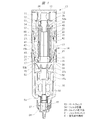
図1に示されるフィルタ10は、流入ポート11と流出ポート12が設けられたポートブロック13を有する。配管やホース等の空気案内部材が流入ポート11に接続され、被処理空気は空気案内部材を介してフィルタ10に供給される。配管やホース等の空気案内部材が流出ポート12に接続され、清浄化された圧縮空気は流出ポート12から流出する。
The
フィルタ10はフィルタ容器14を有し、フィルタ容器14はポートブロック13の下端部に着脱自在に装着される。ポートブロック13が上側、フィルタ容器14が下側の状態で、フィルタ10は使用される。フィルタ10のポートブロック13は、図示しないアタッチメントを介して、図示しない壁面などに取り付けられる。明細書においては、各部材の上下方向は、フィルタ10が使用される状態に基づいて示される。
The
フィルタ容器14には収容室15が設けられている。図1に示したフィルタ容器14は、第1容器16と第2容器17を有する。液体排出孔18が第1容器16の下端部に設けられ、雌ねじ部19が第1容器16の上端部に設けられている。雄ねじ部21が第2容器17の下端部に設けられ、雌ねじ部19が雄ねじ部21にねじ結合される。雌ねじ部22が第2容器17の上端部に設けられ、雌ねじ部22はポートブロック13の雄ねじ部23にねじ結合される。したがって、第1容器16を第2容器17に対して回転させることにより、第1容器16は第2容器17に対して着脱される。第2容器17をポートブロック13に対して回転させることにより、フィルタ容器14はポートブロック13に対して着脱される。ただし、フィルタ容器14の形態としては、第1容器16と第2容器17とが一体となったタイプもある。
The
環状のロック部材24が、第1容器16の上端部の外側に上下動自在に装着される。ロック部材24が第2容器17に係合されると、第1容器16の第2容器17に対する回転が規制される。同様に、環状のロック部材25が第2容器17の上端部の外側に上下動自在に装着される。ロック部材25がポートブロック13に係合されると、第2容器17のポートブロック13に対する回転が規制される。シール部材26は第1容器16と第2容器17の間をシールし、シール部材27は第2容器17とポートブロック13との間をシールする。
An
収容室15は、第1容器16の内部の貯留室15aと、第2容器17の内部のフィルタ室15bとに区画される。エレメント組立体30がフィルタ室15b内に配置される。エレメント組立体30は、濾過機能および凝集機能を有する円筒形状のフィルタエレメント31と、フィルタエレメント31の上端部に固定される上ホルダー32と、フィルタエレメント31の下端部に固定される下ホルダー33とを備える。フィルタエレメント31は、上ホルダー32と下ホルダー33との間に設けられる。
The
上ホルダー32は、フィルタエレメント31の上端面が突き当てられるフランジ部34を有する。排出管35がフランジ部34に設けられ、排出管35は上方に向けて突出している。排出管35は、ポートブロック13に形成された連通孔36に嵌合されて、ポートブロック13に装着される。排出管35は連通孔36により流出ポート12に連通する。下ホルダー33は、環状部37を有し、第2容器17に設けられた環状支持部38に装着される。環状部37は排出孔37aを有し、排出孔37aは貯留室15aに連通する。排出孔37aは、下端部に向かうにしたがって内径が大きくなったテーパ面により形成されている。フランジ部39が環状部37に設けられ、フランジ部39は環状部37から径方向外方に突出している。フィルタエレメント31の下端面がフランジ部39に突き当てられる。
The
空気案内部材41が、フィルタエレメント31の内側に位置して、上ホルダー32と下ホルダー33の間に設けられている。図2〜図4に示されるように、空気案内部材41は、複数の外側ブレード42と、複数の内側ブレード43を有している。複数の外側ブレード42は、円周方向に隙間を隔てて配置される。内側ブレード43は、外側ブレード42よりも径方向内方に配置され、相互に円周方向に隙間を隔てて配置される。外側ブレード42と内側ブレード43は、上ホルダー32と一体に設けられている。
An
図3に示される実施の形態は、3つの外側ブレード42と3つの内側ブレード43を有している。外側ブレード42の円周方向の角度をθ1とし、内側ブレード43の円周方向の角度をθ2とする。外側ブレード42と内側ブレード43は円周方向に延びて、角度θ1と角度θ2の角度はそれぞれ60度以上である。外側ブレード42は円周方向に外側端部44を有し、内側ブレード43は円周方向に内側端部45を有している。それぞれの外側ブレード42の外側端部44と、隣り合う内側ブレード43の内側端部45との間に、スリット46が形成される。外側端部44と内側端部45は、円周方向にスリット46を介して重なっているので、スリット46は円周方向を向いて開口される。外側端部44のエッジと内側端部45のエッジとを結ぶ接線を符号Tで示すと、この接線Tはフィルタ室15bの中心、つまり空気案内部材41の中心を通らない。図3に示される空気案内部材41は、外側ブレード42と内側ブレード43を3つずつ備えているので、スリット46は空気案内部材41に6つ形成されている。ただし、空気案内部材41を構成する外側ブレード42と内側ブレード43の数は、3つに限られることなく、任意の数とすることができる。
The embodiment shown in FIG. 3 has three
エレメント組立体30は、上述のように、上ホルダー32と、下ホルダー33と、これらの間に設けられるフィルタエレメント31と、フィルタエレメント31の内側に設けられる空気案内部材41とを備え、これらの部材を組み立てることにより形成される。エレメント組立体30は、図1に示されるように、ポートブロック13と第2容器17とにより区画されるフィルタ室15b内に収容される。流入ポート11に連通する連通路51がポートブロック13に形成されている。連通路51はエレメント組立体30の外側の流入空間52に連通する。シール部材53aは上ホルダー32とポートブロック13の間をシールする。シール部材53bは、下ホルダー33と環状支持部38との間をシールする。
As described above, the
流入ポート11から流入空間52に流入した被処理空気は、フィルタエレメント31を透過する。被処理空気に含まれる水分、油分は、フィルタエレメント31を透過する過程で衝突、凝集しながらある程度の大きさの液滴に成長する。液滴は、フィルタエレメント31を透過した微細な塵も含んでいる。成長した液滴は、フィルタエレメント31の内周面にまで到達し、自重により内周面に沿って下方に落下する。一部の液滴は、落下する途中でフィルタエレメントの内周面から離れ、空気案内部材41の外壁に衝突して付着し、空気案内部材41の外壁を伝わって下方に移動し、貯留室15aに向けて落下する。さらに、一部の液滴は、空気案内部材41の外壁に衝突することなく、スリット46を通って内側空間47に入る。
The air to be treated that flows into the
フィルタエレメント31を透過した圧縮空気は、空気案内部材41とフィルタエレメント31との間の隙間に入り込んだ後、それぞれのスリット46から空気案内部材41の内部の内側空間47に流入する。内側空間47に流入する圧縮空気は、図3において矢印で示されるように、内側空間47の中心に直接向かうことなく、円周方向に向かってスリット46を通過してから、内側空間47に流入する。これにより、内側空間47にスリット46から流入した圧縮空気は、内側ブレード43の内面に向けて吹き付けられる。
The compressed air that has passed through the
外側ブレード42の内側には、2つのスリット46が対向して位置している。この、対向する2つのスリット46を通過した圧縮空気は、スリット46を通過するときには円周方向に流れ、外側ブレード42の内側の中央付近で衝突する。衝突した2つの圧縮空気の流れは、円周方向から半径方向に向きを変え、中心に向かう。2つの圧縮空気が衝突する、外側ブレード42の内側の中央付近は、吹き溜まり領域である。吹き溜まり領域は、外側ブレード42の内壁中央に、軸方向に沿って形成される。吹き溜まり領域に集められた液滴は、その大きさがさらに成長するので、外側ブレード42の内壁に沿って、自重により速やかに落下する。
Two
さらに、外側ブレード42の内壁中央に、軸方向に溝を設けることにより、吹き溜まり領域での液滴の滞留と成長を助長できる。
Further, by providing a groove in the axial direction in the center of the inner wall of the
このように、フィルタエレメント31を透過しながら大きく成長した液滴は、その大部分が空気案内部材の外壁に衝突・付着して落下する。空気案内部材の外壁に衝突しなかった液滴は、スリット46から内側空間47内に流入し、圧縮空気により外側ブレード42の内面に向けて吹き付けられて外側ブレード42の内面に付着する。つまり、空気案内部材41の外壁に衝突しなかった水分、油分は、内側空間47の中心に向けて吹き付けられることなく、空気案内部材41としての外側ブレード42に付着する。
As described above, most of the droplets that have grown large while passing through the
空気案内部材41の外側および外側ブレード42の内面に付着した液滴は、ある程度の大きさとなっており、突発的に圧縮空気の流速変動が発生しても、内側空間47の中心部に移動することが防止される。これにより、異物が、排出管35から流出ポート12に向けて流出することが防止され、フィルタ10による異物の除去効率を高めることができる。
The droplets adhering to the outside of the
小径案内管48が、上ホルダー32のフランジ部34に設けられ、下方に突出している。小径案内管48は、空気案内部材41の径方向内方に向けて突出している。下方に向けて開口した遮断空間49が、小径案内管48と空気案内部材41の上端部との間に設けられている。遮断空間49は、内側ブレード43や外側ブレード42の内面に付着した液滴が、小径案内管48や排出管35に向かって表面を伝わって移動することを、阻止する。したがって、内側空間47から排出管35に向けて流れる圧縮空気に、異物は入り込まない。
A small
空気案内部材41の外側や外側ブレード42の内面に付着した液滴は、自重で下方に移動し、液体排出孔37aを通って貯留室15aに落下する。排出管54が液体排出孔18に設けられ、貯留室15a内に溜まった液滴等の異物は排出管54を介して外部に排出される。脚部55が4枚の板状部材から構成され、貯留室15aに配置される。4枚の板状部材は径方向中心部から放射状に延びている。排出孔18をシールするためのシール部材56が、脚部55に設けられている。操作ノブ57が、フィルタ容器14の下端部に回転自在に装着され、排出管54に噛み合っている。操作ノブ57を回転させると、排出管54が上下動する。操作ノブ57により排出管54を上昇移動させると、シール部材56と第1容器16との密閉状態が開放される。これにより、貯留室15a内の液体等の異物は排出管54を介して外部に排出される。
The droplets adhering to the outside of the
バッフル板58が脚部55の上に配置され、バッフル板58は排出孔37aに対向する。複数のフィン59が、バッフル板58の外周部に設けられている。それぞれのフィン59は、上方に突出し、放射方向に延びている。排出孔37aを通って貯留室15a内に落下した液滴は、フィン59により第2容器17の内周面に向けて案内されて貯留室15aの下部に集められる。フィルタ容器14は透明性を有する樹脂材料により形成されており、貯留室15a内に溜められた液体の量は外部から目視される。液体の量が増加したことが目視されたときには、作業者が操作ノブ57を操作することにより、貯留室15a内の液体等の異物は外部に排出される。
A
図5は、変形例であるエレメント組立体30を示す縦断面図である。図6は、図5に示されたエレメント組立体30を縦割りした切断部分を示し、図6(A)はエレメント組立体30の断面を上方から見た斜視図であり、図6(B)はエレメント組立体30の断面を下方から見た斜視図である。
FIG. 5 is a longitudinal sectional view showing an
図5および図6に示されるフィルタ10においては、図1および図2に示した小径案内管48は、上ホルダー32には設けられていない。このように、小径案内管48を設けない形態においても、異物の除去効率を高めることができる。
In the
図7は、他の変形例であるエレメント組立体30を縦割した切断部分を示し、図7(A)はエレメント組立体30の断面を上方から見た斜視図であり、図7(B)はエレメント組立体30の断面を下方から見た斜視図である。図8は、図7に示したエレメント組立体30の横断面図であり、図9は、図7に示したエレメント組立体30の空気案内部材41と上ホルダー32を示す斜視図である。
FIG. 7 shows a cut portion obtained by vertically dividing an
図7〜図9に示すエレメント組立体30においては、空気案内部材41が円周方向に渦巻き形状となった単一のブレード部材61により形成されている。スリット46が、ブレード部材61の円周方向の両端部62,63の間に、形成されている。両端部62,63はスリット46を介して円周方向に重なり、スリット46は円周方向に開口している。外側端部62のエッジと内側端部63のエッジとを結ぶ接線Tは、図3に示した空気案内部材41と同様に、フィルタ室15bの中心、つまり空気案内部材41の中心を通らない。つまり、内側空間47に流入する圧縮空気は、内側空間47の中心に直接向かうことなく、円周方向に向かってスリット46を通過してから、内側空間47に流入する。これにより、内側空間47にスリット46から流入した圧縮空気は、ブレード部材61の内面に向けて吹き付けられる。したがって、スリット46から内側空間47内に流入した液滴は、ブレード部材61の内面に付着するので、排出管35に向けて飛散することが抑制される。これにより、フィルタ10による異物の除去効率を高めることができる。
In the
図7に示されるように、上ホルダー32には小径案内管48が設けられている。ただし、図4に示される形態のように、上ホルダー32に小径案内管48が設けられていない形態とすることもできる。
As shown in FIG. 7, the
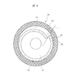
図10は、さらに他の変形例であるエレメント組立体を縦割した切断部分を示し、図10(A)はエレメント組立体を上方から見た斜視図であり、図10(B)はエレメント組立体を下方から見た斜視図である。図11は、図10に示したエレメント組立体の横断面図である。図12は、図10に示したエレメント組立体における空気案内部材と上ホルダーを示す斜視図である。 FIG. 10 shows a cut portion obtained by vertically dividing an element assembly which is still another modified example. FIG. 10 (A) is a perspective view of the element assembly as viewed from above. FIG. 10 (B) is an element assembly. It is the perspective view which looked at the solid from the lower part. FIG. 11 is a cross-sectional view of the element assembly shown in FIG. 12 is a perspective view showing an air guide member and an upper holder in the element assembly shown in FIG.
図10〜図12に示すエレメント組立体30においては、空気案内部材41が円周方向に傾斜する複数の傾斜ブレード65により成形されている。それぞれの傾斜ブレード65は、円周方向の外方端部66と円周方向の内方端部67とを有している。内方端部67は、隣接する傾斜ブレード65の外方端部66よりも径方向内方に位置している。外方端部66は、それぞれの傾斜ブレード65の中心部分を通る基準円に対して外側に位置し、内方端部67は内側に位置するように、傾斜ブレード65は傾斜している。それぞれの内方端部67と、これに隣り合う他の傾斜ブレード65の外方端部66との間に、複数のスリット46が形成されている。それぞれのスリット46は傾斜ブレード65の内面に沿う方向に開口されている。
In the
フィルタエレメント31を透過しながら大きく成長した液滴は、フィルタエレメント31の内側に沿って落下する。落下せずにフィルタエレメント31の内側から離脱した液滴は、その大部分が傾斜ブレード65の外壁に衝突・付着して落下する。傾斜ブレード65の外壁に衝突しなかった液滴は、スリット46から内側空間47内に流入し、圧縮空気により傾斜ブレード65の内面に向けて吹き付けられて、傾斜ブレード65内面に付着する。
Droplets that have grown large while passing through the
外方端部66のエッジと内方端部67のエッジとを結ぶ接線Tは、上述した空気案内部材41と同様に、フィルタ室15bの中心、つまり空気案内部材41の中心を通らない。したがって、スリット46を通過した圧縮空気は、内側空間47の中心に直接向かうことなく、円周方向に向かってスリット46を通過してから、内側空間47に流入する。従って、圧縮空気は、内側空間47内において旋回する。圧縮空気は、旋回によって速度を増す。圧縮空気に含まれる液滴は、早い速度で傾斜ブレード65内面に衝突して付着する。旋回による圧縮空気の高速化は、傾斜ブレード65内面に対する液滴の衝突・付着を効率化する。高速化によって、より多くの液滴が傾斜ブレード65内面に衝突して付着し、落下するので、液滴が排出管35に向けて流出することが抑制される。これにより、フィルタ10による異物の除去効率を高めることができる。
The tangent line T connecting the edge of the
図8から図12に示したエレメント組立体を、図1のフィルタ10に適用すると、複数のフィン59は以下の効果を有する。つまり、圧縮空気は、旋回しながら液体排出孔37aから貯留室15aに向けて流れこむが、フィン59により旋回が抑制される。旋回が抑制された圧縮空気は、空気案内部材41の中心部を流れて排出管35に向かう。
When the element assembly shown in FIGS. 8 to 12 is applied to the
図13は、他の実施の形態であるフィルタ10を示す縦断面図である。このフィルタ10におけるエレメント組立体30は、図1〜図4と同様の構造となっている。図13に示したフィルタ10においては、図1に示された脚部55とバッフル板58が設けられていない。液体排出孔18を有するスリーブ71が、フィルタ容器14の底部に設けられ、ドレンコックとしての排出管72が、スリーブ71にねじ結合される。開閉弁体74が、排出管72に係合し、フィルタ容器14に設けられた弁座シール73を開閉する。排出孔75が開閉弁体74に設けられ、排出管72を回転させると、開閉弁体74が上下動し、排出孔75と貯留室15aとを連通状態と遮断状態とに操作される。したがって、貯留室15a内に溜められた液体の量が増加したときには、作業者が排出管72を操作することにより、貯留室15a内の液体等の異物は外部に排出される。
FIG. 13 is a longitudinal sectional view showing a
上述した形態においては、空気案内部材41は上ホルダー32と一体に形成されている。ただし、空気案内部材41は、下ホルダー33と一体に形成されても良い。また、空気案内部材41は、上ホルダー32および下ホルダー33とは別部材として形成されても良い。いずれの形態としても、フィルタエレメント31を透過することにより、水分、油分が凝集されてある程度の大きさに成長した液滴は、フィルタエレメント31の内面を伝わって落下する。フィルタエレメント31の内面から離脱した液滴は、空気案内部材41の外面や内面に吹き付けられるので、液滴は空気案内部材41の外面や内面に付着して落下する。このように、異物が流出ポート12に向かう圧縮空気に混入することが防止される。
In the embodiment described above, the
本発明は前記実施の形態に限定されるものではなく、その要旨を逸脱しない範囲で種々変更可能である。例えば、図示するフィルタ10は、貯留室15a内に溜まった液体等の異物を手動操作により外部に排出するようにしたドレンフィルタであるが、貯留室15a内に溜められた異物が所定量となると、自動的に外部に異物を排出するようにしたオートドレン式のフィルタにも、この発明を適用することができる。
The present invention is not limited to the above-described embodiment, and various modifications can be made without departing from the scope of the invention. For example, the illustrated
10 フィルタ
11 流入ポート
12 流出ポート
13 ポートブロック
14 フィルタ容器
15a 貯留室
15b フィルタ室
16 第1容器
17 第2容器
30 エレメント組立体
31 フィルタエレメント
32 上ホルダー
33 下ホルダー
34 フランジ部
35 排出管
36 連通孔
37 環状部
37a 排出孔
38 環状支持部
39 フランジ部
41 空気案内部材
42 外側ブレード
43 内側ブレード
46 スリット
47 内側空間
48 小径案内管
49 遮断空間
61 ブレード部材
65 傾斜ブレード
DESCRIPTION OF
Claims (13)
被処理空気が供給される流入ポート、および清浄化された圧縮空気を流出する流出ポートが設けられたポートブロックと、
前記ポートブロックに装着され、前記ポートブロックとともに収容室を形成するフィルタ容器と、
前記収容室に配置されるエレメント組立体と、を有し、
前記エレメント組立体は、
上ホルダー、下ホルダー、および前記上ホルダーと前記下ホルダーとの間に設けられるフィルタエレメントと、
前記上ホルダーと前記下ホルダーの間に設けられ、前記フィルタエレメントの内周面に沿って延びる空気案内部材とを有し、
前記フィルタエレメントを透過した圧縮空気を、円周方向に傾斜させて前記空気案内部材の内面に案内するスリットが前記空気案内部材に設けられ、
前記空気案内部材は、円周方向の内側端部と外側端部とを備え、
隣り合う前記内側端部と前記外側端部は、前記スリットを介して円周方向に重なり合う、フィルタ。 A filter that removes foreign matter contained in compressed air and purifies the compressed air,
A port block provided with an inflow port to which the air to be treated is supplied and an outflow port through which the purified compressed air flows out;
A filter container mounted on the port block and forming a storage chamber together with the port block;
An element assembly disposed in the storage chamber,
The element assembly is
An upper holder, a lower holder, and a filter element provided between the upper holder and the lower holder;
An air guide member provided between the upper holder and the lower holder and extending along an inner peripheral surface of the filter element;
A slit that guides the compressed air that has passed through the filter element to the inner surface of the air guide member in a circumferential direction is provided in the air guide member ,
The air guide member includes an inner end and an outer end in the circumferential direction,
The adjacent inner end and the outer end adjacent to each other overlap in the circumferential direction via the slit .
被処理空気が供給される流入ポート、および清浄化された圧縮空気を流出する流出ポートが設けられたポートブロックと、
前記ポートブロックに装着され、前記ポートブロックとともに収容室を形成するフィルタ容器と、
前記収容室に配置されるエレメント組立体と、を有し、
前記エレメント組立体は、
上ホルダー、下ホルダー、および前記上ホルダーと前記下ホルダーとの間に設けられるフィルタエレメントと、
前記上ホルダーと前記下ホルダーの間に設けられ、前記フィルタエレメントの内周面に沿って延びる空気案内部材とを有し、
前記フィルタエレメントを透過した圧縮空気を、円周方向に傾斜させて前記空気案内部材の内面に案内するスリットが前記空気案内部材に設けられ、
前記空気案内部材は、円周方向に傾斜する複数の傾斜ブレードを有し、それぞれの前記傾斜ブレードの円周方向の内方端部と、当該内方端部と隣り合う他の前記傾斜ブレードの円周方向の外方端部との間に複数の前記スリットが形成された、フィルタ。 A filter that removes foreign matter contained in compressed air and purifies the compressed air,
A port block provided with an inflow port to which the air to be treated is supplied and an outflow port through which the purified compressed air flows out;
A filter container mounted on the port block and forming a storage chamber together with the port block;
An element assembly disposed in the storage chamber,
The element assembly is
An upper holder, a lower holder, and a filter element provided between the upper holder and the lower holder;
An air guide member provided between the upper holder and the lower holder and extending along an inner peripheral surface of the filter element;
A slit that guides the compressed air that has passed through the filter element to the inner surface of the air guide member in a circumferential direction is provided in the air guide member,
The air guide member has a plurality of inclined blades inclined in the circumferential direction, and each of the inclined blades has an inner end portion in the circumferential direction and other inclined blades adjacent to the inner end portion. A filter in which a plurality of the slits are formed between the outer ends in the circumferential direction.
上ホルダー、下ホルダー、および前記上ホルダーと前記下ホルダーとの間に設けられるフィルタエレメントと、
前記上ホルダーと前記下ホルダーの間に設けられ、前記フィルタエレメントの内周面に沿って延びる空気案内部材とを有し、
前記フィルタエレメントを透過した圧縮空気を、円周方向に傾斜させて前記空気案内部材の内面に案内するスリットが、前記空気案内部材に設けられ、
前記空気案内部材は、円周方向の内側端部と外側端部とを備え、
隣り合う前記内側端部と前記外側端部は、前記スリットを介して円周方向に重なり合う、エレメント組立体。 An element assembly used for a filter that removes foreign matters contained in compressed air and purifies the compressed air,
An upper holder, a lower holder, and a filter element provided between the upper holder and the lower holder;
An air guide member provided between the upper holder and the lower holder and extending along an inner peripheral surface of the filter element;
A slit that guides the compressed air that has passed through the filter element to the inner surface of the air guide member in a circumferential direction is provided in the air guide member,
The air guide member includes an inner end and an outer end in the circumferential direction,
The adjacent inner end portion and the outer end portion overlap each other in the circumferential direction through the slit .
前記空気案内部材は、円周方向に隙間を隔てて配置される複数の外側ブレードと、前記外側ブレードよりも径方向内方に配置され円周方向に隙間を隔てて配置される複数の内側ブレードとを有し、前記外側ブレードの円周方向の外側端部と、前記外側ブレードと径方向に隣り合う前記内側ブレードの円周方向の内側端部との間に複数の前記スリットが形成された、エレメント組立体。 The element assembly according to claim 8.
The air guide member includes a plurality of outer blades arranged with a gap in the circumferential direction, and a plurality of inner blades arranged radially inward with respect to the outer blade and arranged with a gap in the circumferential direction. A plurality of slits are formed between a circumferential outer end of the outer blade and a circumferential inner end of the inner blade that is radially adjacent to the outer blade. Element assembly.
前記空気案内部材は、円周方向に渦巻き形状の単一のブレード部材により形成され、前記ブレード部材の両端部の間に前記スリットが形成された、エレメント組立体。 The element assembly according to claim 8.
The element assembly, wherein the air guide member is formed of a single blade member having a spiral shape in a circumferential direction, and the slit is formed between both ends of the blade member.
上ホルダー、下ホルダー、および前記上ホルダーと前記下ホルダーとの間に設けられるフィルタエレメントと、
前記上ホルダーと前記下ホルダーの間に設けられ、前記フィルタエレメントの内周面に沿って延びる空気案内部材とを有し、
前記フィルタエレメントを透過した圧縮空気を、円周方向に傾斜させて前記空気案内部材の内面に案内するスリットが、前記空気案内部材に設けられ、
前記空気案内部材は、円周方向に傾斜する複数の傾斜ブレードを有し、それぞれの前記傾斜ブレードの円周方向の内方端部と、当該内方端部と隣り合う他の前記傾斜ブレードの円周方向の外方端部との間に複数の前記スリットが形成された、エレメント組立体。 An element assembly used for a filter that removes foreign matters contained in compressed air and purifies the compressed air,
An upper holder, a lower holder, and a filter element provided between the upper holder and the lower holder;
An air guide member provided between the upper holder and the lower holder and extending along an inner peripheral surface of the filter element;
A slit that guides the compressed air that has passed through the filter element to the inner surface of the air guide member in a circumferential direction is provided in the air guide member,
The air guide member has a plurality of inclined blades inclined in the circumferential direction, and each of the inclined blades has an inner end portion in the circumferential direction and other inclined blades adjacent to the inner end portion. An element assembly in which a plurality of the slits are formed between the outer ends in the circumferential direction.
前記スリットを通過した圧縮空気を案内する小径案内管が、前記空気案内部材の内側に位置されて前記上ホルダーに設けられた、エレメント組立体。 The element assembly according to any one of claims 8 to 11,
An element assembly in which a small-diameter guide tube that guides compressed air that has passed through the slit is provided inside the air guide member and provided in the upper holder.
前記空気案内部材が前記上ホルダーに一体に設けられた、エレメント組立体。 The element assembly according to any one of claims 8 to 12,
An element assembly in which the air guide member is provided integrally with the upper holder.
Priority Applications (6)
| Application Number | Priority Date | Filing Date | Title |
|---|---|---|---|
| JP2015063534A JP6370251B2 (en) | 2015-03-26 | 2015-03-26 | Element assembly and filter |
| DE112015006372.2T DE112015006372B4 (en) | 2015-03-26 | 2015-08-26 | ELEMENT ARRANGEMENT AND FILTER |
| PCT/JP2015/074096 WO2016151883A1 (en) | 2015-03-26 | 2015-08-26 | Element assembly and filter |
| CN201590001406.XU CN207286977U (en) | 2015-03-26 | 2015-08-26 | Element assembly and filter |
| US15/561,114 US10561973B2 (en) | 2015-03-26 | 2015-08-26 | Element assembly and filter |
| TW104137584A TWI645890B (en) | 2015-03-26 | 2015-11-13 | Filter and its component components |
Applications Claiming Priority (1)
| Application Number | Priority Date | Filing Date | Title |
|---|---|---|---|
| JP2015063534A JP6370251B2 (en) | 2015-03-26 | 2015-03-26 | Element assembly and filter |
Publications (3)
| Publication Number | Publication Date |
|---|---|
| JP2016182548A JP2016182548A (en) | 2016-10-20 |
| JP2016182548A5 JP2016182548A5 (en) | 2017-06-01 |
| JP6370251B2 true JP6370251B2 (en) | 2018-08-08 |
Family
ID=56978114
Family Applications (1)
| Application Number | Title | Priority Date | Filing Date |
|---|---|---|---|
| JP2015063534A Active JP6370251B2 (en) | 2015-03-26 | 2015-03-26 | Element assembly and filter |
Country Status (6)
| Country | Link |
|---|---|
| US (1) | US10561973B2 (en) |
| JP (1) | JP6370251B2 (en) |
| CN (1) | CN207286977U (en) |
| DE (1) | DE112015006372B4 (en) |
| TW (1) | TWI645890B (en) |
| WO (1) | WO2016151883A1 (en) |
Families Citing this family (6)
| Publication number | Priority date | Publication date | Assignee | Title |
|---|---|---|---|---|
| JP6436827B2 (en) * | 2015-03-26 | 2018-12-12 | 株式会社コガネイ | Element assembly and filter |
| US10408492B2 (en) * | 2016-01-15 | 2019-09-10 | Hamilton Sundstrand Corporation | Drain hole orifice device |
| US20180172041A1 (en) * | 2016-12-20 | 2018-06-21 | Baker Hughes Incorporated | Temperature regulated components having cooling channels and method |
| DE102017222731B4 (en) * | 2017-12-14 | 2023-06-15 | Festo Se & Co. Kg | Filter device for filtering compressed air |
| TWI789909B (en) * | 2021-09-16 | 2023-01-11 | 玖鑢豪科技股份有限公司 | air filter |
| CN117552958B (en) * | 2024-01-12 | 2024-03-22 | 山西省第二地质工程勘察院有限公司 | Air compressor machine air intake system |
Family Cites Families (28)
| Publication number | Priority date | Publication date | Assignee | Title |
|---|---|---|---|---|
| US2828831A (en) * | 1953-11-02 | 1958-04-01 | Gen Motors Corp | Fluid cleaner |
| US3208229A (en) * | 1965-01-28 | 1965-09-28 | Fulton Cryogenics Inc | Vortex tube |
| US3771295A (en) * | 1969-07-31 | 1973-11-13 | H Wheeler | Separater apparatus for handling compressed air |
| DE2219846A1 (en) | 1972-04-22 | 1973-10-31 | Haas & Sohn Ernst W | AIR PURIFIER, PRESENTLY FOR ROOM AIR CLEANING |
| SE465813B (en) * | 1990-03-23 | 1991-11-04 | Sundstrom Safety Ab | CYCLONE CHAMBER WITH DROP DETAILS |
| US5119640A (en) * | 1990-10-22 | 1992-06-09 | Conrad Richard H | Freeze-thaw air dryer |
| US5591243A (en) * | 1993-09-10 | 1997-01-07 | Col-Ven S.A. | Liquid trap for compressed air |
| JPH07204440A (en) * | 1994-01-28 | 1995-08-08 | Koganei Corp | Air filter |
| US6032804A (en) * | 1997-06-16 | 2000-03-07 | Paulson; Jerome I | Cyclonic dust collector |
| US5846271A (en) * | 1997-07-08 | 1998-12-08 | Reading Technologies, Inc. | Multi-stage compressed gas filter |
| US6004365A (en) | 1997-10-17 | 1999-12-21 | Fiacco; Paul | Air filtering device |
| AU1675099A (en) * | 1997-12-15 | 1999-07-05 | Domnick Hunter Limited | Filter assembly |
| US6093227A (en) * | 1998-08-27 | 2000-07-25 | Itt Manufacturing Enterprises, Inc. | Air filter with labyrinth air flow pattern through an air filter insert |
| EP1155724A1 (en) * | 2000-05-19 | 2001-11-21 | Munters Euroform GmbH | Filter candle |
| CN2486746Y (en) * | 2001-07-12 | 2002-04-17 | 陈栢辉 | Pneumatic air dewatering device |
| GB0515266D0 (en) * | 2005-07-26 | 2005-08-31 | Domnick Hunter Ltd | Separator assembly |
| DE202006006084U1 (en) * | 2006-04-12 | 2007-08-16 | Mann + Hummel Gmbh | Multi-stage device for separating drops of liquid from gases |
| JP5384441B2 (en) * | 2010-07-15 | 2014-01-08 | 株式会社テイエルブイ | Gas-liquid separator |
| JP5663394B2 (en) * | 2011-05-06 | 2015-02-04 | 株式会社コガネイ | Container detachment device for tempering equipment |
| JP5713289B2 (en) | 2011-05-09 | 2015-05-07 | Smc株式会社 | Case structure of fluid pressure equipment |
| JP5765560B2 (en) | 2011-05-09 | 2015-08-19 | Smc株式会社 | Filter device |
| JP5666379B2 (en) * | 2011-05-19 | 2015-02-12 | 株式会社コガネイ | Swirl generator |
| US9174225B2 (en) * | 2011-05-19 | 2015-11-03 | Koganei Corporation | Filter |
| JP5791384B2 (en) * | 2011-06-16 | 2015-10-07 | 株式会社テイエルブイ | Gas-liquid separator |
| TW201515711A (en) * | 2013-10-31 | 2015-05-01 | Koganei Ltd | Filter |
| JP6226789B2 (en) * | 2014-03-20 | 2017-11-08 | 株式会社コガネイ | Filter Regulator |
| US9689310B2 (en) * | 2014-05-06 | 2017-06-27 | William BOATENG | Airplane engine bird strike protection guard |
| JP6436827B2 (en) * | 2015-03-26 | 2018-12-12 | 株式会社コガネイ | Element assembly and filter |
-
2015
- 2015-03-26 JP JP2015063534A patent/JP6370251B2/en active Active
- 2015-08-26 US US15/561,114 patent/US10561973B2/en active Active
- 2015-08-26 CN CN201590001406.XU patent/CN207286977U/en not_active Expired - Fee Related
- 2015-08-26 WO PCT/JP2015/074096 patent/WO2016151883A1/en active Application Filing
- 2015-08-26 DE DE112015006372.2T patent/DE112015006372B4/en active Active
- 2015-11-13 TW TW104137584A patent/TWI645890B/en active
Also Published As
| Publication number | Publication date |
|---|---|
| DE112015006372B4 (en) | 2021-12-30 |
| TWI645890B (en) | 2019-01-01 |
| WO2016151883A1 (en) | 2016-09-29 |
| CN207286977U (en) | 2018-05-01 |
| JP2016182548A (en) | 2016-10-20 |
| TW201634102A (en) | 2016-10-01 |
| DE112015006372T5 (en) | 2017-12-14 |
| US10561973B2 (en) | 2020-02-18 |
| US20180126312A1 (en) | 2018-05-10 |
Similar Documents
| Publication | Publication Date | Title |
|---|---|---|
| JP6436827B2 (en) | Element assembly and filter | |
| JP6370251B2 (en) | Element assembly and filter | |
| JP5628089B2 (en) | filter | |
| JP5819716B2 (en) | filter | |
| JP5767322B2 (en) | filter | |
| JP5519024B2 (en) | Separation system for separating particles of a first fluid from a second fluid stream | |
| WO2015033414A1 (en) | Gas-liquid separation device | |
| WO2012157146A1 (en) | Swirling-flow generator | |
| RU2536991C1 (en) | Device for gas purification from liquid and solid particles | |
| JP5890797B2 (en) | Air filter | |
| KR20200058544A (en) | Oil management structure in crankcase ventilation | |
| KR100908883B1 (en) | The water separator | |
| GB2522303A (en) | Apparatus for coalescing particles of a first fluid entrained in a flow of a second fluid | |
| JP2010172821A (en) | Filter device | |
| WO2016151881A1 (en) | Element assembly and filter | |
| WO2012157139A1 (en) | Filter | |
| JP2022533903A (en) | Air/oil separation apparatus and method | |
| US10301893B2 (en) | Shale-gas separator discharge diffuser | |
| KR20230089120A (en) | Filter for condensate draining device | |
| WO2016151884A1 (en) | Filter | |
| UA68515A (en) | Filter for removal of admixtures from transported gas |
Legal Events
| Date | Code | Title | Description |
|---|---|---|---|
| A521 | Request for written amendment filed |
Free format text: JAPANESE INTERMEDIATE CODE: A523 Effective date: 20170405 |
|
| A621 | Written request for application examination |
Free format text: JAPANESE INTERMEDIATE CODE: A621 Effective date: 20170405 |
|
| A131 | Notification of reasons for refusal |
Free format text: JAPANESE INTERMEDIATE CODE: A131 Effective date: 20180306 |
|
| A521 | Request for written amendment filed |
Free format text: JAPANESE INTERMEDIATE CODE: A523 Effective date: 20180419 |
|
| TRDD | Decision of grant or rejection written | ||
| A01 | Written decision to grant a patent or to grant a registration (utility model) |
Free format text: JAPANESE INTERMEDIATE CODE: A01 Effective date: 20180703 |
|
| A61 | First payment of annual fees (during grant procedure) |
Free format text: JAPANESE INTERMEDIATE CODE: A61 Effective date: 20180710 |
|
| R150 | Certificate of patent or registration of utility model |
Ref document number: 6370251 Country of ref document: JP Free format text: JAPANESE INTERMEDIATE CODE: R150 |
|
| R250 | Receipt of annual fees |
Free format text: JAPANESE INTERMEDIATE CODE: R250 |
|
| R250 | Receipt of annual fees |
Free format text: JAPANESE INTERMEDIATE CODE: R250 |