KR20160039299A - Lighting control circuit, illuminating lamp using the lighting control circuit, and lighting device using the illuminating lamp - Google Patents
Lighting control circuit, illuminating lamp using the lighting control circuit, and lighting device using the illuminating lamp Download PDFInfo
- Publication number
- KR20160039299A KR20160039299A KR1020167007638A KR20167007638A KR20160039299A KR 20160039299 A KR20160039299 A KR 20160039299A KR 1020167007638 A KR1020167007638 A KR 1020167007638A KR 20167007638 A KR20167007638 A KR 20167007638A KR 20160039299 A KR20160039299 A KR 20160039299A
- Authority
- KR
- South Korea
- Prior art keywords
- control circuit
- lighting control
- ballast
- smoothing capacitor
- lighting
- Prior art date
Links
Images


Classifications
-
- H05B33/0815—
-
- H—ELECTRICITY
- H05—ELECTRIC TECHNIQUES NOT OTHERWISE PROVIDED FOR
- H05B—ELECTRIC HEATING; ELECTRIC LIGHT SOURCES NOT OTHERWISE PROVIDED FOR; CIRCUIT ARRANGEMENTS FOR ELECTRIC LIGHT SOURCES, IN GENERAL
- H05B47/00—Circuit arrangements for operating light sources in general, i.e. where the type of light source is not relevant
- H05B47/10—Controlling the light source
- H05B47/105—Controlling the light source in response to determined parameters
-
- H—ELECTRICITY
- H05—ELECTRIC TECHNIQUES NOT OTHERWISE PROVIDED FOR
- H05B—ELECTRIC HEATING; ELECTRIC LIGHT SOURCES NOT OTHERWISE PROVIDED FOR; CIRCUIT ARRANGEMENTS FOR ELECTRIC LIGHT SOURCES, IN GENERAL
- H05B47/00—Circuit arrangements for operating light sources in general, i.e. where the type of light source is not relevant
- H05B47/10—Controlling the light source
-
- F21K9/17—
-
- F—MECHANICAL ENGINEERING; LIGHTING; HEATING; WEAPONS; BLASTING
- F21—LIGHTING
- F21K—NON-ELECTRIC LIGHT SOURCES USING LUMINESCENCE; LIGHT SOURCES USING ELECTROCHEMILUMINESCENCE; LIGHT SOURCES USING CHARGES OF COMBUSTIBLE MATERIAL; LIGHT SOURCES USING SEMICONDUCTOR DEVICES AS LIGHT-GENERATING ELEMENTS; LIGHT SOURCES NOT OTHERWISE PROVIDED FOR
- F21K9/00—Light sources using semiconductor devices as light-generating elements, e.g. using light-emitting diodes [LED] or lasers
- F21K9/20—Light sources comprising attachment means
- F21K9/27—Retrofit light sources for lighting devices with two fittings for each light source, e.g. for substitution of fluorescent tubes
-
- F—MECHANICAL ENGINEERING; LIGHTING; HEATING; WEAPONS; BLASTING
- F21—LIGHTING
- F21V—FUNCTIONAL FEATURES OR DETAILS OF LIGHTING DEVICES OR SYSTEMS THEREOF; STRUCTURAL COMBINATIONS OF LIGHTING DEVICES WITH OTHER ARTICLES, NOT OTHERWISE PROVIDED FOR
- F21V19/00—Fastening of light sources or lamp holders
- F21V19/0075—Fastening of light sources or lamp holders of tubular light sources, e.g. ring-shaped fluorescent light sources
- F21V19/008—Fastening of light sources or lamp holders of tubular light sources, e.g. ring-shaped fluorescent light sources of straight tubular light sources, e.g. straight fluorescent tubes, soffit lamps
-
- H05B33/0818—
-
- H05B33/0842—
-
- F21Y2101/02—
-
- F—MECHANICAL ENGINEERING; LIGHTING; HEATING; WEAPONS; BLASTING
- F21—LIGHTING
- F21Y—INDEXING SCHEME ASSOCIATED WITH SUBCLASSES F21K, F21L, F21S and F21V, RELATING TO THE FORM OR THE KIND OF THE LIGHT SOURCES OR OF THE COLOUR OF THE LIGHT EMITTED
- F21Y2115/00—Light-generating elements of semiconductor light sources
- F21Y2115/10—Light-emitting diodes [LED]
-
- Y—GENERAL TAGGING OF NEW TECHNOLOGICAL DEVELOPMENTS; GENERAL TAGGING OF CROSS-SECTIONAL TECHNOLOGIES SPANNING OVER SEVERAL SECTIONS OF THE IPC; TECHNICAL SUBJECTS COVERED BY FORMER USPC CROSS-REFERENCE ART COLLECTIONS [XRACs] AND DIGESTS
- Y02—TECHNOLOGIES OR APPLICATIONS FOR MITIGATION OR ADAPTATION AGAINST CLIMATE CHANGE
- Y02B—CLIMATE CHANGE MITIGATION TECHNOLOGIES RELATED TO BUILDINGS, e.g. HOUSING, HOUSE APPLIANCES OR RELATED END-USER APPLICATIONS
- Y02B20/00—Energy efficient lighting technologies, e.g. halogen lamps or gas discharge lamps
- Y02B20/30—Semiconductor lamps, e.g. solid state lamps [SSL] light emitting diodes [LED] or organic LED [OLED]
-
- Y02B20/386—
Abstract
본 발명에 따른 조명등용의 점등 제어 회로는, 상용 교류 전력이 공급되는 안정기에 접속되어, 교류를 직류로 변환하는 정류부; 상기 정류부의 출력측에 마련되어, 이 출력측으로부터 출력된 직류에 포함된 교류 성분을 제거하는 평활 커패시터; 상기 평활 커패시터의 양단에 직렬로 접속된 복수 개의 고체 상태 발광 소자로 흐르는 전류에 온-오프 제어를 행하며, 스위칭 소자를 구비하는 구동 회로; 및 상기 안정기와 상기 평활 커패시터 사이의 전력 공급 시스템에 마련되어 있는 인덕터를 포함한다.A lighting control circuit for an illumination lamp according to the present invention comprises: a rectifying part connected to a ballast to which commercial AC power is supplied and converting AC into DC; A smoothing capacitor provided on an output side of the rectifying unit to remove an AC component included in a direct current output from the output side; A driving circuit which performs on-off control on a current flowing to a plurality of solid-state light-emitting elements connected in series at both ends of the smoothing capacitor, the switching circuit including a switching element; And an inductor provided in a power supply system between the ballast and the smoothing capacitor.

Description
본 발명은 고체 상태 발광 소자에서의 점등 제어를 행하는 데 사용되는 점등 제어 회로, 이 점등 제어 회로를 이용한 조명등 및 이 조명등을 구비한 조명 기구에 관한 것이다.The present invention relates to a lighting control circuit used for performing lighting control in a solid-state light emitting device, an illumination lamp using the lighting control circuit, and a lighting apparatus provided with the illumination lamp.
종래 기술에서는, 필라멘트 전극을 갖는 형광등 대신에, 소비 전력이 적은 고체 상태 발광 소자, 예컨대 발광 다이오드(LED) 등을 이용하는 조명등이 제안되어 있다(일본 특허 출원 공개 제2008-277188호 공보 참조).In the prior art, instead of a fluorescent lamp having a filament electrode, an illumination lamp using a solid-state light emitting element with low power consumption, such as a light emitting diode (LED), has been proposed (see Japanese Patent Application Laid-Open No. 2008-277188).
일본 특허 출원 공개 제2008-277188호 공보에 개시된 내용에 따르면, 글로 스타트형 형광등을 이용한 조명 기구, 또는 래피드 스타트형 형광등을 이용한 조명 기구에 고체 상태 발광 소자를 구비한 조명등을 설치할 수 없을 뿐만 아니라, 형광등용의 인버터형 안정기를 구비한 조명 기구에 고체 상태 발광 소자를 구비한 조명등을 교환 가능하게 설치할 수 없다.According to the contents disclosed in Japanese Patent Application Laid-Open No. 2008-277188, it is not only impossible to provide a lighting apparatus using a glow-start type fluorescent lamp or a lighting apparatus equipped with a solid-state light-emitting element in a lighting apparatus using a rapid start type fluorescent lamp, It is not possible to replace the illumination lamp having the solid state light emitting element with the lighting apparatus having the inverter type ballast for fluorescent lamps in a replaceable manner.
인버터형 안정기를 구비한 형광등용의 조명 기구는, 전력 절약, 고효율, 50 ㎐와 60 ㎐ 주파수 겸용 가능, 저소음, 깜빡임 없음 등의 특징을 갖는다. 그러나, 인버터형의 형광등용 안정기를 구비한 조명 기구에 고체 상태 발광 소자를 구비한 조명등을 설치하는 경우에는, 안정기에 의해 확인되는 고체 상태 발광 소자를 구비한 조명등의 임피던스가 낮고, 안정기가 과전류 보호 동작으로 인해 정상적으로 작동되지 않으며, 이에 따라 고체 상태 발광 소자를 구비한 조명등이 점등되지 않을 가능성이 있다.The lighting fixtures for fluorescent lamps equipped with inverter type ballasts are characterized by power saving, high efficiency, 50 Hz and 60 Hz frequencies, low noise, and no flicker. However, when an illuminating lamp having a solid-state light emitting element is provided in a lighting device having an inverter type fluorescent lamp ballast, the impedance of the lighting lamp having the solid-state light emitting element confirmed by the ballast is low, The operation is not normally performed, and accordingly, the illumination lamp having the solid state light emitting element may not be turned on.
일반적으로, 기존의 인버터형의 형광등용 안정기에서는, 형광등용 안정기에 흐르는 전류가 100 mA 이하일 때, 과전압 보호 회로가 작동되고, 형광등용 안정기에 흐르는 전류가 500 mA 이상일 때, 과전류 보호 회로가 작동된다.In general, in the conventional inverter type fluorescent lamp ballast, when the current flowing through the fluorescent lamp ballast is 100 mA or less, the overvoltage protection circuit is activated, and when the current flowing through the fluorescent ballast is 500 mA or more, the overcurrent protection circuit is operated .
일본 특허 출원 공개 제2008-277188호 공보에 개시된 내용에 따르면, 안정기에 의해 확인되는 고체 상태 발광 소자를 구비한 조명등의 임피던스는, 기존의 형광등의 필라멘트에 근사하는 임피던스를 갖는 직류 저항과 커패시터를 이용함으로써 높게 설정되지만; 기존의 형광등용 조명 기구에 고체 상태 발광 소자를 구비한 조명등을 대신 설치하는 경우에는, 고주파 노이즈의 저감, 돌입 전류의 억제 등의 해결해야 할 과제가 여전히 존재한다.According to the disclosure of Japanese Patent Application Laid-Open No. 2008-277188, the impedance of an illumination lamp having a solid-state light-emitting element confirmed by a ballast is determined by using a DC resistance having an impedance approximating a filament of a conventional fluorescent lamp and a capacitor But is set high; There is still a problem to be solved such as reduction of high-frequency noise, suppression of inrush current, and the like when an illuminating lamp having a solid-state light emitting element is provided instead of a conventional lighting apparatus for a fluorescent lamp.
본 발명의 목적은, 기존의 형광등용 조명 기구에, 고체 상태 발광 소자를 구비한 조명등을 형광등 대신에 설치하는 경우, 점등 제어를 행하는 데 사용되기에 적합한 점등 제어 회로, 이 점등 제어 회로를 이용한 조명등 및 이 조명등을 구비한 조명 기구를 제공하는 것이다.SUMMARY OF THE INVENTION An object of the present invention is to provide a lighting control circuit which is suitable for use in performing lighting control when an illumination lamp having a solid state light emitting element is provided in place of a fluorescent lamp in a conventional lighting apparatus for a fluorescent lamp, And a luminaire provided with the luminaire.
상기 목적을 달성하기 위해, 본 발명의 일 실시형태는, 조명등용의 점등 제어 회로로서, 상용 교류 전력이 공급되는 안정기에 접속되어, 교류를 직류로 변환하는 정류부; 상기 정류부의 출력측에 마련되어, 이 출력측으로부터 출력된 직류에 포함된 교류 성분을 제거하는 평활 커패시터; 상기 평활 커패시터의 양단에 직렬로 접속된 복수 개의 고체 상태 발광 소자로 흐르는 전류에 온-오프 제어를 행하며, 스위칭 소자를 구비하는 구동 회로; 및 상기 안정기와 상기 평활 커패시터 사이의 전력 공급 시스템에 마련되어 있는 인덕터를 포함하는 조명등용의 점등 제어 회로를 제공한다.In order to achieve the above object, one embodiment of the present invention is a lighting control circuit for an illumination lamp, comprising: a rectifying section connected to a ballast to which commercial AC power is supplied, for converting AC into DC; A smoothing capacitor provided on an output side of the rectifying unit to remove an AC component included in a direct current output from the output side; A driving circuit which performs on-off control on a current flowing to a plurality of solid-state light-emitting elements connected in series at both ends of the smoothing capacitor, the switching circuit including a switching element; And an inductor provided in a power supply system between the ballast and the smoothing capacitor.
상기 목적을 달성하기 위해, 본 발명의 일 실시형태는, 직관형 조명등으로서, 한 쌍의 전극 핀을 갖는 베이스에 의해 양단부가 각각 밀봉되어 있는 직관 내에, 상용 교류 전력이 공급되는 안정기에 접속되어, 교류를 직류로 변환하는 정류부; 상기 정류부의 출력측에 마련되어, 이 출력측으로부터 출력된 직류에 포함된 교류 성분을 제거하는 평활 커패시터; 상기 평활 커패시터의 양단에 직렬로 접속된 복수 개의 고체 상태 발광 소자; 스위칭 소자가 마련되며, 상기 복수 개의 고체 상태 발광 소자로 흐르는 전류에 온-오프 제어를 행하는 구동 회로; 및 상기 안정기와 상기 평활 커패시터 사이의 전력 공급 시스템에 마련되어, 상기 안정기에 의해 확인되는 상기 평활 커패시터의 임피던스를 증가시키는 인덕터를 포함하는, 점등 제어 회로를 구비하는 직관형 조명등을 제공한다.In order to achieve the above object, an embodiment of the present invention is an intuitive illumination lamp, which is connected to a ballast to which commercial AC power is supplied, in an inside of a straight tube in which both ends are sealed by a base having a pair of electrode pins, A rectifying part for converting an alternating current into a direct current; A smoothing capacitor provided on an output side of the rectifying unit to remove an AC component included in a direct current output from the output side; A plurality of solid state light emitting elements connected in series to both ends of the smoothing capacitor; A driving circuit provided with a switching element and performing ON / OFF control on a current flowing to the plurality of solid state light emitting elements; And an inductor that is provided in a power supply system between the ballast and the smoothing capacitor and increases an impedance of the smoothing capacitor identified by the ballast.
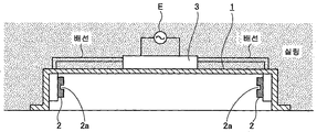
도 1은 본 발명의 일 실시형태에 따라 고체 상태 발광 소자를 구비한 조명등의 설치가 가능한, 기존의 인버터형의 형광등용 안정기를 구비한 조명 기구의 개요를 보여주는 단면도이다.
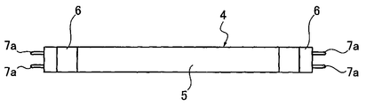
도 2는 도 1에 도시된 조명 기구에 설치 가능한 조명등의 외관을 개략적으로 보여주는 정면도이다.
도 3은 도 2에 도시된 조명등의 단면을 확대하여 그 개요를 보여주는 도면이다.
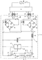
도 4는 본 발명의 일 실시형태에 따른 고체 상태 발광 소자를 구비한 조명등의 점등 제어 회로의 일례를 보여주는 결선도이다.
도 5는 본 발명의 일 실시형태에 따른 고체 상태 발광 소자를 구비한 조명등의 점등 제어 회로의 다른 예를 보여주는 결선도이다.
도 6은 본 발명의 일 실시형태에 따른 고체 상태 발광 소자를 구비한 조명등의 점등 제어 회로의 다른 예를 보여주는 결선도이다.
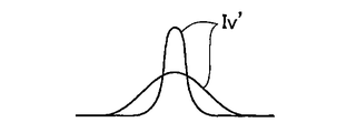
도 7은 돌입 전류의 파형의 일례를 보여주는 도면이다.
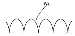
도 8은 전파(全波) 정류 파형의 일례를 보여주는 도면이다.
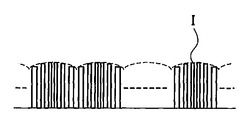
도 9는 평활 전류의 일례를 보여주는 도면이다.FIG. 1 is a cross-sectional view showing an outline of an existing inverter-type lamp fixture having a fluorescent lamp ballast capable of installing an illumination lamp having a solid-state light-emitting element according to an embodiment of the present invention.
Fig. 2 is a front view schematically showing the appearance of an illumination lamp that can be installed in the lighting apparatus shown in Fig. 1. Fig.
3 is an enlarged cross-sectional view of the illumination lamp shown in Fig.
4 is a wiring diagram showing an example of a lighting control circuit of an illumination lamp having a solid-state light-emitting element according to an embodiment of the present invention.
5 is a wiring diagram showing another example of a lighting control circuit of an illumination lamp having a solid state light emitting element according to an embodiment of the present invention.
6 is a wiring diagram showing another example of a lighting control circuit of an illumination lamp having a solid state light emitting element according to an embodiment of the present invention.
7 is a diagram showing an example of the waveform of an inrush current.
8 is a diagram showing an example of a full wave rectified waveform.
9 is a view showing an example of a smoothing current.
이하에서는, 도면을 참조로 하여, 본 발명의 일 실시형태에 따른 점등 제어 회로와, 이 점등 제어 회로를 이용한 조명등, 그리고 이 조명등을 이용한 조명 기구를 설명한다.Hereinafter, with reference to the drawings, a lighting control circuit according to an embodiment of the present invention, an illumination lamp using the illumination control circuit, and a lighting apparatus using the illumination lamp will be described.
도 1에서, 도면 부호 1은 직관형 조명등이 설치되는 반사 우산을 나타낸다. 이 반사 우산(1)에는, 그 연장 방향의 양단부에, 한 쌍의 소켓(2)이 간격을 두고 마련되어 있다. 이 반사 우산(1)에는, 상용 교류 전원(E)으로부터 전력이 공급되는 기존의 형광등용 안정기가 마련되어 있다.1, reference numeral 1 denotes a reflection umbrella provided with an intaglio light. In this reflection umbrella 1, a pair of
이 조명 기구에는, 기존의 직관형 형광등이 설치 가능하지만; 이 기존의 직관형 형광등 대신에, 도 4에 도시된 직관형 조명등(4)이 설치되어 있다. 이 조명등(4)의 직관(5)의 양단부 각각은 베이스(6)에 의해 밀봉되어 있다. 이 베이스(6)에는, 전력 공급 시스템의 일부분을 구성하는 한 쌍의 전극 핀(7a, 7b)이 마련되어 있다.In this lighting apparatus, a conventional straight fluorescent lamp can be installed; Instead of the conventional straight tube fluorescent lamp, an intaglio
직관(5)에는, 도 3에 도시된 바와 같이, 직관(5)의 길이방향으로 연장되는 회로 기판(8)이 마련되어 있다. 이 회로 기판(8)의 일면측에는, 복수의 고체 상태 발광 소자(9)가 직렬로 접속된 직렬 발광체(10)가 마련되어 있다. 이 회로 기판(8)의 타면측에는, 점등 제어 회로(11)가 마련되어 있다.In the
안정기(3)에는 상용 교류 전원(E)이 접속되어 있다. 이 상용 교류 전원(E)의 주파수는 예컨대 50㎐/60㎐이다. 이 안정기(3)의 출력측이 한 쌍의 소켓(2)에 접속되어 있다. 한 쌍의 소켓(2)은 각각 한 쌍의 전극 단자(2a, 2a)를 갖는다. 한 쌍의 전극 핀(7a, 7b)은 한 쌍의 전극 단자(2a, 2a)에 접속되어 있다.A commercial AC power supply E is connected to the
점등 제어 회로(11)는, 도 4 내지 도 6에 도시된 바와 같이, 한 쌍의 정류부(12), 평활 커패시터(13), 구동 회로로서의 정전류 제어 회로(14), 및 인덕터(15)를 포함한다. 정류부(12)는, 상용 교류 전원(E)으로부터 전력이 공급되는 안정기(3)에 접속되어 있고, 교류를 직류로 변환한다.The
바람직하게는, 정전압 다이오드(D1~D4)를 갖는 브리지형 전파 정류 회로가 정류부(12)를 구성한다. 각 정류부(12)의 입력측이 한 쌍의 전극 단자(7a, 7a)에 퓨즈(HS)를 통해 접속되어 있다. 각 정류부(12)의 출력측이 평활 커패시터(13)의 양단의 각 전극에 접속되어 있다.Preferably, the bridge type full-wave rectification circuit having the constant-voltage diodes D1 to D4 constitute the rectifying
평활 커패시터(13)는, 출력측으로부터 출력된 직류(Iv)에 포함된 교류 성분을 제거한다. 여기서는, 평활 커패시터(13)로서 전계 커패시터가 사용된다. 평활 커패시터(13)의 양단의 전극에는, 직렬 발광체(10)의 양단이 접속되어 있다. 직렬 발광체(10)를 구성하는 고체 상태 발광 소자(9)로서, 예컨대 발광 다이오드(LED)가 사용된다. 또한, 복수의 직렬 발광체(10)가 병렬로 접속될 수 있다.The
정전류 제어 회로(14)는 개략적으로, 스위칭 소자(16), DC(직류) 커트용 초크 코일(17), 전류 검출용 저항기(18), 피드백용 제너 다이오드(19) 및 제어 IC(20)를 포함한다. 예컨대, MOSFET(Metal-Oxide-Semiconductor Field-Effect Transistor)가 스위칭 소자(16)를 구성한다.The constant
스위칭 소자(16)의 드레인이, 고체 상태 발광 소자(9)의 캐소드에 DC 커트용 초크 코일(17)을 통해 접속되어 있다. 스위칭 소자(16)의 소스가, 전력 공급 시스템의 마이너스측에 전류 검출용 저항기(18)를 통해 접속되어 있다.The drain of the
제어 IC(20)는 직렬 발광체(10)에 흐르는 전류(I)를 전류 검출용 저항기(18)에 의해 검출하고, 직렬 발광체(10)에 흐르는 전류(I)가 일정하도록 스위칭 소자(16)의 온-오프 제어를 행한다. 제어 IC(20)의 온-오프 주파수는 20 ㎑ 내지 70 ㎑의 범위로 설정되어 있다(가정용 원격 제어기의 33 ㎑ 내지 41 ㎑ 범위의 주파수는 제외).The
때때로, 스위칭 소자(16)가 상시 온 상태인 경우도 또한 포함된다.Sometimes, the case where the
DC 커트용 초크 코일(17) 및 피드백용 제너 다이오드(19)는, 스위칭 소자(16)가 온 상태에서 오프 상태로 스위칭될 때, 유도 기전력에 의해 화살표 F의 방향으로 직류(I')를 통과시키는 기능을 갖는다.The DC
인덕터(15)는 안정기(3)와 평활 커패시터(13) 사이의 전력 공급 시스템에 마련되는 것이 바람직하다.The
안정기(3)와 평활 커패시터(13) 사이의 전력 공급 시스템에 인덕터(15)를 마련함으로써, 안정기(3)에 의해 확인되는 평활 커패시터(13)의 임피던스를 증가시킬 수 있다. 따라서, 평활 커패시터(13)로 흐르는 돌입 전류(Iv')(도 7 참조)의 피크값을 저감할 수 있다. 인덕터(15)는 안정기(3)에 의해 확인되는 평활 커패시터(13)의 임피던스를 증가시킨다.The impedance of the
즉, 실효 전류를 저감시킬 수 있으므로, 안정기(3)의 과전류 보호가 작동하는 것을 방지할 수 있다. 고체 상태 발광 소자를 구비한 조명등(4)이 기존의 형광등용 조명 기구에 설치되는 경우라도, 정상적으로 작동할 수 있다.In other words, since the effective current can be reduced, it is possible to prevent the overcurrent protection of the
바람직하게는, 인덕터(15)로서 고주파 코일이 사용된다. 바람직하게는, 고주파 코일의 인덕턴스는 100 μΗ 내지 1 mH이다.Preferably, a high frequency coil is used as the
도 4에 도시된 실시형태에서는, 평활 커패시터(13)와 정류부(12)의 출력측 사이에 1개의 고주파 코일이 마련되어 있다. 이 실시형태에서는, 전력 공급 시스템의 플러스측에 고주파 코일이 마련되어 있지만, 고주파 코일은 전력 공급 시스템의 마이너스측에 마련될 수 있다.In the embodiment shown in Fig. 4, one high-frequency coil is provided between the smoothing
또한, 도 5에 도시된 바와 같이, 안정기(3)와 정류부(12)의 입력측 사이의 전력 공급 시스템에 한 쌍의 고주파 코일이 마련될 수 있다.5, a pair of high-frequency coils may be provided in the power supply system between the
또한, 도 6에 도시된 바와 같이, 평활 커패시터(13)와 정류부(12)의 출력측 사이의 전력 공급 시스템에 1개의 고주파 코일이 마련될 수 있고, 안정기(3)와 정류부(12)의 입력측 사이의 전력 공급 시스템에 한 쌍의 고주파 코일이 마련될 수 있다.6, one high-frequency coil may be provided in the power supply system between the smoothing
도 5 및 도 6에 도시된 바와 같이, 안정기(3)와 정류부(12)의 입력측 사이에 한 쌍의 고주파 코일을 마련할 필요가 있다. 그러나, 소형의 고주파 코일을 사용하는 것도 가능하므로, 조명등을 소형화하는 것도 가능하다.It is necessary to provide a pair of high frequency coils between the
파워 스위치(SW)를 켜는 순간, 상용 교류가 조명등(4)의 전극 핀(7a, 7b)에 안정기(3)를 통해 공급되고, 정류부(12)에 의해 상용 교류가 직류(Iv)로 변환되며, 이 직류(Iv)는 평활 커패시터(13)에 돌입 전류(Iv')로서 흘러들어간다. 그러나, 본 발명의 실시형태에 따르면, 점등 제어 회로에 있어서, 조명등(4)의 전력 공급 시스템에 인덕터(15)가 마련되어 있고, 인덕터(15)가 저항 성분으로서 작용하므로, 돌입 전류(Iv')의 피크값이 도 7에 도시된 바와 같이 저감된다.The commercial alternating current is supplied to the electrode pins 7a and 7b of the illuminating
따라서, 안정기(3)에 과전류가 흐르는 것을 방지할 수 있다. 따라서, 실효 전류가 저감되며, 안정기(3)의 과전류 보호가 작동하는 것을 방지할 수 있다. 그 결과, 고체 상태 발광 소자(6)를 갖는 조명등(4)이 기존의 형광등용 조명 기구에 설치되는 경우에도, 이 조명등을 정상적으로 작동시킬 수 있다.Therefore, it is possible to prevent the overcurrent from flowing to the
이어서, 점등 제어 회로에 따르면, 도 8에 도시된 바와 같이, 정류부(12)에 의해 교류에 전파(全波) 정류가 행해지고, 이 교류는 반정현파 전류(Wa)로 변환된다. 이 반정현파 전류(Wa)는 평활 커패시터(13)에 의해 직류(I)로 변환된다.Next, according to the lighting control circuit, as shown in Fig. 8, the rectifying
도 9에 도시된 바와 같이, 제어 IC(20)가 스위칭 소자(16)의 온-오프 제어를 행하여, 직류(I)는 PWM(Pulse Width Modulation) 방식으로 샘플링되고, 고체 상태 발광 소자(9)로 흐르는 직류(I)는 정전류가 되도록 제어된다.9, the
때때로, 스위칭 소자(16)가 상시 온 상태인 경우에도, 직류(I)가 흐른다.Sometimes, even when the switching
본 실시형태에서, 인덕터(15)는 조명등(4)에 장착된 점등 제어 회로에 마련되며, 이에 따라 낙뢰의 서지 등으로 인한 외부 노이즈의 혼입을 방지할 수 있고, 이 외부 노이즈에 의해 야기되는 조명등(4)의 깜빡거림을 저감할 수 있다.In the present embodiment, the
또한, 조명등(4) 내부에 발생하는 고주파 노이즈가 새어나가는 것을 억제하는 효과도 있다.In addition, there is an effect of suppressing leakage of high-frequency noise generated in the inside of the
특히, 안정기에 의해 확인되는 고체 상태 발광 소자를 구비한 조명등의 임피던스가, 기존의 형광등의 필라멘트에 근사하는 임피던스를 갖는 직류 저항과 커패시터를 이용함으로써 높게 설정되는 경우에 비해, 소비 전력이 적다는 점이 유익하다.Particularly, compared to the case where the impedance of an illumination lamp having a solid-state light-emitting element confirmed by a ballast is set high by using a DC resistance and a capacitor having an impedance approximate to a filament of a conventional fluorescent lamp, helpful.
또한, 돌입 전류(Iv')를 저감할 수 있고, 이에 따라 퓨즈가 끊기고 차단기가 트립되는 것을 방지할 수 있다.In addition, it is possible to reduce the inrush current Iv ', thereby preventing the fuse from being blown and the circuit breaker from tripping.
또한, 본 발명의 실시형태에 따르면, 인덕터(15)는 교류 임피던스로서도 작용하며, 이에 따라 기존의 인버터형의 형광등용 안정기를 구비한 조명 기구 뿐만 아니라, 기존의 글로 스타트형의 형광등용 안정기 및 기존의 래피드 스타트형의 형광등용 안정기를 구비한 조명기에도 조명등(4)을 설치할 수 있다.In addition, according to the embodiment of the present invention, the
본 발명의 실시형태에 따르면, 기존의 형광등용 안정기를 변경하지 않고서, 기존의 조명 기구에 고체 상태 발광 소자를 구비한 조명등을 형광등을 대신하여 설치하는 경우에도, 조명등의 점등 제어를 순조롭게 행할 수 있다.According to the embodiment of the present invention, it is possible to smoothly control the lighting of the illumination lamp even when the illumination lamp having the solid state light emitting element in the existing lighting apparatus is installed in place of the fluorescent lamp, without changing the existing ballast for fluorescent lamp .
또한, 고주파 노이즈를 저감할 수 있고, 돌입 전류를 억제할 수 있으며, 외부 노이즈의 혼입을 방지할 수 있다.Further, the high-frequency noise can be reduced, the inrush current can be suppressed, and the mixing of external noise can be prevented.
특히, 안정기에 의해 확인되는 고체 상태 발광 소자를 구비한 조명등의 임피던스가, 기존의 형광등의 필라멘트에 근사하는 임피던스를 갖는 직류 저항 및 커패시터를 이용함으로써 높게 설정되는 경우에 비해, 소비 전력이 적다는 점이 유익하다.Particularly, the fact that the impedance of the illumination lamp having the solid-state light-emitting element confirmed by the ballast is lower than the case where the impedance is set high by using the DC resistance and the capacitor having the impedance approximate to the filament of the conventional fluorescent lamp helpful.
본 발명을 예시적인 실시형태에 관하여 설명하였지만, 본 발명은 이에 한정되지 않는다. 당업자라면 이하의 청구범위에 의해 한정되는 본 발명의 범위를 벗어나지 않고서도, 전술한 실시형태에 대해 변형을 실시할 수 있음은 물론이다.While the present invention has been described with reference to exemplary embodiments, the invention is not limited thereto. It will be apparent to those skilled in the art that modifications may be made to the above-described embodiments without departing from the scope of the present invention which is defined by the following claims.
관련 출원에 대한 상호 참조Cross-reference to related application
본 출원은 2011년 7월 6일자로 출원된 일본 특허 출원 제2011-149941호를 기초로 하고, 우선권으로 주장하며, 이 특허 출원의 내용은 그 전체가 본원에 참조로 인용되어 있다.This application is based upon and claims the benefit of priority from Japanese Patent Application No. 2011-149941 filed on July 6, 2011, the contents of which are incorporated herein by reference in their entirety.
Claims (13)
상용 교류 전력이 공급되는 안정기에 접속되어 교류를 직류로 변환하는 정류부와,
상기 정류부의 출력측에 마련되어, 이 출력측으로부터 출력된 직류에 포함되는 교류 성분을 제거하는 평활 커패시터와,
상기 안정기와 상기 평활 커패시터의 사이의 전력 공급 라인에 마련되고, 상기 안정기측으로부터 상기 평활 커패시터를 봤을 때의 인피던스를 높이고, 상기 평활 커패시터측에서 발생하는 고주파 노이즈를 제어하는 인덕터와,
상기 고체 발광 소자에 대하여 정전류 제어하는 정전류 제어 회로
를 포함하는 점등 제어 회로.A lighting control circuit for controlling a solid light emitting element,
A rectifier connected to the ballast to which commercial AC power is supplied to convert AC into DC;
A smoothing capacitor provided on an output side of the rectifying part for removing an AC component included in a direct current output from the output side,
An inductor that is provided in a power supply line between the ballast and the smoothing capacitor and increases an impedance when the smoothing capacitor is seen from the ballast side and controls a high frequency noise generated on the smoothing capacitor side;
A constant current control circuit for controlling the constant current to the solid light-
And a control circuit.
직관형 형광등에 사용되는 반사 우산과,
상기 반사 우산의 양단부에 간격을 두고 마련된 한 쌍의 소켓과,
상용 교류 전원이 공급 가능한 형광등용 안정기
를 포함하고,
제12항에 기재된 직관형 조명등의 한 쌍의 전극 핀이 상기 한 쌍의 소켓에 각각 접속되는 것인 조명 기구.As a lighting apparatus,
A reflection umbrella used for an intentional fluorescent lamp,
A pair of sockets provided at both ends of the reflection umbrella at intervals,
Fluorescent lamp ballast with commercial AC power supply
Lt; / RTI >
And a pair of electrode pins of an intaglio illumination lamp according to claim 12 are connected to the pair of sockets, respectively.
Applications Claiming Priority (3)
| Application Number | Priority Date | Filing Date | Title |
|---|---|---|---|
| JP2011149941A JP5830986B2 (en) | 2011-07-06 | 2011-07-06 | Lighting control circuit, illumination lamp using the lighting control circuit, and luminaire using the illumination lamp |
| JPJP-P-2011-149941 | 2011-07-06 | ||
| PCT/JP2012/067021 WO2013005751A1 (en) | 2011-07-06 | 2012-06-27 | Lighting control circuit, illuminating lamp using the lighting control circuit, and lighting device using the illuminating lamp |
Related Parent Applications (1)
| Application Number | Title | Priority Date | Filing Date |
|---|---|---|---|
| KR1020137035095A Division KR101609038B1 (en) | 2011-07-06 | 2012-06-27 | Lighting control circuit, illuminating lamp using the lighting control circuit, and lighting device using the illuminating lamp |
Publications (1)
| Publication Number | Publication Date |
|---|---|
| KR20160039299A true KR20160039299A (en) | 2016-04-08 |
Family
ID=47437099
Family Applications (2)
| Application Number | Title | Priority Date | Filing Date |
|---|---|---|---|
| KR1020137035095A KR101609038B1 (en) | 2011-07-06 | 2012-06-27 | Lighting control circuit, illuminating lamp using the lighting control circuit, and lighting device using the illuminating lamp |
| KR1020167007638A KR20160039299A (en) | 2011-07-06 | 2012-06-27 | Lighting control circuit, illuminating lamp using the lighting control circuit, and lighting device using the illuminating lamp |
Family Applications Before (1)
| Application Number | Title | Priority Date | Filing Date |
|---|---|---|---|
| KR1020137035095A KR101609038B1 (en) | 2011-07-06 | 2012-06-27 | Lighting control circuit, illuminating lamp using the lighting control circuit, and lighting device using the illuminating lamp |
Country Status (7)
| Country | Link |
|---|---|
| US (2) | US9357599B2 (en) |
| EP (1) | EP2730148A4 (en) |
| JP (1) | JP5830986B2 (en) |
| KR (2) | KR101609038B1 (en) |
| CN (2) | CN103650642B (en) |
| TW (1) | TWI469687B (en) |
| WO (1) | WO2013005751A1 (en) |
Families Citing this family (23)
| Publication number | Priority date | Publication date | Assignee | Title |
|---|---|---|---|---|
| US9871404B2 (en) | 2011-12-12 | 2018-01-16 | Cree, Inc. | Emergency lighting devices with LED strings |
| US10117295B2 (en) | 2013-01-24 | 2018-10-30 | Cree, Inc. | LED lighting apparatus for use with AC-output lighting ballasts |
| US9093893B2 (en) * | 2012-03-02 | 2015-07-28 | Panasonic Intellectual Property Management Co., Ltd. | DC power supply circuit |
| US10136483B2 (en) * | 2012-06-15 | 2018-11-20 | Aleddra Inc. | Solid-state lighting with auto-select settings for line voltage and ballast voltage |
| JP6007680B2 (en) * | 2012-08-31 | 2016-10-12 | 株式会社リコー | Lighting control circuit, illumination lamp using the lighting control circuit, and control method of the lighting control circuit |
| US10045406B2 (en) * | 2013-01-24 | 2018-08-07 | Cree, Inc. | Solid-state lighting apparatus for use with fluorescent ballasts |
| US10104723B2 (en) * | 2013-01-24 | 2018-10-16 | Cree, Inc. | Solid-state lighting apparatus with filament imitation for use with florescent ballasts |
| JP2014154429A (en) * | 2013-02-12 | 2014-08-25 | Panasonic Corp | Dimming lighting circuit, and illuminating device using the same |
| KR20140105658A (en) * | 2013-02-22 | 2014-09-02 | 주식회사 하이딥 | Led lighting device using ballast |
| KR101521834B1 (en) * | 2013-04-11 | 2015-05-21 | 주식회사 하이딥 | Led lighting device using ballast |
| DE202013004107U1 (en) | 2013-04-29 | 2013-05-10 | Osram Gmbh | Retrofit lamp |
| JP2015050191A (en) * | 2013-09-04 | 2015-03-16 | ルミリッチ シーオー エルティディ | Light emitting diode lamp using alternating current voltage |
| JP2015060722A (en) * | 2013-09-19 | 2015-03-30 | ローム株式会社 | Led illuminating lamp |
| MX362549B (en) | 2013-09-25 | 2019-01-24 | Silicon Hill Bv | Led lighting system. |
| KR101539083B1 (en) * | 2014-04-10 | 2015-07-24 | 주식회사 아모센스 | Led lamp using switching circuit |
| JP6455030B2 (en) | 2014-09-01 | 2019-01-23 | 株式会社リコー | Illumination lamp and illumination device |
| JP2016085813A (en) | 2014-10-23 | 2016-05-19 | 株式会社リコー | Illumination lamp and lighting device |
| EP3275288B1 (en) | 2015-03-26 | 2021-05-05 | Silicon Hill B.V. | Led lighting system |
| JP6492954B2 (en) * | 2015-05-15 | 2019-04-03 | 株式会社リコー | Lighting lamp, lighting device and lighting control circuit |
| JP6683942B2 (en) * | 2015-07-24 | 2020-04-22 | 株式会社リコー | Lighting control device, illumination lamp, and illumination device |
| ES2829384T3 (en) * | 2017-01-03 | 2021-05-31 | Signify Holding Bv | A light-emitting diode, LED, upgrade tube to replace a fluorescent tube |
| CN109819543A (en) * | 2017-11-21 | 2019-05-28 | 通用电气照明解决方案有限公司 | LED illumination component and its driving circuit |
| TWI693769B (en) * | 2018-11-28 | 2020-05-11 | 緯創資通股份有限公司 | Power supply system, electronic device and power supply method thereof |
Family Cites Families (42)
| Publication number | Priority date | Publication date | Assignee | Title |
|---|---|---|---|---|
| CA2169519A1 (en) * | 1995-02-15 | 1996-08-16 | John H. Covington | Techniques for controlling remote lamp loads |
| JPH11135274A (en) * | 1997-10-30 | 1999-05-21 | Toshiba Tec Corp | Led light system |
| KR100320060B1 (en) | 1999-10-07 | 2002-01-09 | 이광연 | Electronic ballast for luminescent lamp with over-voltage protection circuit |
| JP4585663B2 (en) | 2000-08-04 | 2010-11-24 | 東芝ライテック株式会社 | Filter circuit, filter device and discharge lamp lighting device |
| KR20030023372A (en) | 2001-09-13 | 2003-03-19 | 최승희 | Power supply circuit of electronic ballast |
| JP2003142290A (en) * | 2001-10-31 | 2003-05-16 | Toshiba Lighting & Technology Corp | Discharge lamp lighting device and bulb-shaped fluorescent lamp |
| US6784624B2 (en) * | 2001-12-19 | 2004-08-31 | Nicholas Buonocunto | Electronic ballast system having emergency lighting provisions |
| JP3929885B2 (en) * | 2002-12-06 | 2007-06-13 | シーケーディ株式会社 | LED lighting apparatus, LED lighting apparatus manufacturing apparatus, and LED lighting apparatus manufacturing method |
| JP2006211361A (en) * | 2005-01-28 | 2006-08-10 | Denso Corp | Communication apparatus |
| JP2008052994A (en) * | 2006-08-23 | 2008-03-06 | Nec Lighting Ltd | Lighting device and control circuit |
| JP4270279B2 (en) * | 2007-01-05 | 2009-05-27 | 株式会社デンソー | Control device for vehicle alternator |
| KR20080079881A (en) | 2007-02-28 | 2008-09-02 | 주식회사 미디어테크놀로지 | Stabilizer and illumination control system for high intensity discharge lamp |
| WO2008136458A1 (en) | 2007-05-01 | 2008-11-13 | Sharp Kabushiki Kaisha | Illumination device and lamp using the same |
| JP4994101B2 (en) * | 2007-05-01 | 2012-08-08 | シャープ株式会社 | LED illumination lamp and lamp fixture using the LED illumination lamp |
| TWM323020U (en) * | 2007-06-20 | 2007-12-01 | Ching-Huei Chen | Illuminating lamps and lanterns using spotlight |
| KR100844538B1 (en) | 2008-02-12 | 2008-07-08 | 에스엠크리에이션 주식회사 | Led lamp using the fluorescent socket with the ballast |
| JP2009105355A (en) | 2007-10-23 | 2009-05-14 | Daiichi-Tsusho Co Ltd | Led lighting equipment |
| EP2213144A1 (en) * | 2007-10-26 | 2010-08-04 | Lighting Science Group Corporation | High efficiency light source with integrated ballast |
| US8502454B2 (en) * | 2008-02-08 | 2013-08-06 | Innosys, Inc | Solid state semiconductor LED replacement for fluorescent lamps |
| US7554319B1 (en) | 2008-02-28 | 2009-06-30 | Youling Li | Circuits and methods for voltage sensing |
| JP2009245790A (en) | 2008-03-31 | 2009-10-22 | Nippon Telegr & Teleph Corp <Ntt> | Lighting device |
| WO2009136322A1 (en) | 2008-05-05 | 2009-11-12 | Philips Intellectual Property & Standards Gmbh | Light emitting diode system |
| JP4582196B2 (en) * | 2008-05-29 | 2010-11-17 | Tdk株式会社 | Inductor component mounting structure |
| KR100893906B1 (en) | 2008-07-11 | 2009-04-21 | 김형배 | Led lighting lamp and led lighting apparatus |
| JP4328379B1 (en) * | 2008-10-06 | 2009-09-09 | エン−ハイテク株式会社 | LED fluorescent lamp |
| US20100102729A1 (en) * | 2008-10-10 | 2010-04-29 | Rethink Environmental | Light emitting diode assembly |
| JP2010157480A (en) | 2008-10-25 | 2010-07-15 | Ki Ho Nam | Led lighting device |
| WO2010047447A1 (en) | 2008-10-25 | 2010-04-29 | Nam Ki-Ho | Led illumination device |
| US8664880B2 (en) * | 2009-01-21 | 2014-03-04 | Ilumisys, Inc. | Ballast/line detection circuit for fluorescent replacement lamps |
| EP2222134A3 (en) * | 2009-02-05 | 2015-12-30 | Myung Koo Park | LED fluorescent lamp |
| KR100933076B1 (en) * | 2009-02-05 | 2009-12-21 | 금호전기주식회사 | Led fluorescent lamp |
| JP5033825B2 (en) * | 2009-03-06 | 2012-09-26 | 株式会社光波 | vending machine |
| JP2010212162A (en) * | 2009-03-11 | 2010-09-24 | Hiroshi Sasaki | Luminaire using light-emitting element |
| JP5156036B2 (en) * | 2009-03-30 | 2013-03-06 | テクルックス 株式会社 | LED lighting device |
| JP5500476B2 (en) * | 2009-05-28 | 2014-05-21 | 株式会社アイ・ライティング・システム | Power supply device and lighting system for LED lamp for lighting |
| JP2011044316A (en) | 2009-08-20 | 2011-03-03 | Panasonic Electric Works Co Ltd | Lighting deice |
| JP5463532B2 (en) * | 2009-09-14 | 2014-04-09 | 裕仁 丸山 | LED lighting device |
| JP5541934B2 (en) | 2009-09-25 | 2014-07-09 | パナソニック株式会社 | Driving device for lighting circuit and lighting device |
| WO2011063302A2 (en) * | 2009-11-19 | 2011-05-26 | ElectraLED Inc. | Fluorescent light fixture assembly with led lighting element and converter modules |
| KR20110062243A (en) | 2009-12-03 | 2011-06-10 | 삼성엘이디 주식회사 | Led illumination apparatus using electronic ballast for fluorescent lamp |
| CN201795360U (en) * | 2010-08-26 | 2011-04-13 | 常熟市保得利计算机科技有限公司 | LED fluorescent lamp |
| JP2012195221A (en) | 2011-03-17 | 2012-10-11 | Ricoh Co Ltd | Constant voltage generation circuit and lighting apparatus |
-
2011
- 2011-07-06 JP JP2011149941A patent/JP5830986B2/en not_active Ceased
-
2012
- 2012-06-27 CN CN201280033512.7A patent/CN103650642B/en not_active Expired - Fee Related
- 2012-06-27 US US14/131,037 patent/US9357599B2/en active Active
- 2012-06-27 WO PCT/JP2012/067021 patent/WO2013005751A1/en active Application Filing
- 2012-06-27 EP EP12807188.3A patent/EP2730148A4/en not_active Ceased
- 2012-06-27 KR KR1020137035095A patent/KR101609038B1/en active IP Right Grant
- 2012-06-27 CN CN201710014835.6A patent/CN106879134A/en not_active Withdrawn
- 2012-06-27 KR KR1020167007638A patent/KR20160039299A/en not_active Application Discontinuation
- 2012-07-03 TW TW101123924A patent/TWI469687B/en not_active IP Right Cessation
-
2016
- 2016-04-15 US US15/130,583 patent/US9743470B2/en not_active Expired - Fee Related
Also Published As
| Publication number | Publication date |
|---|---|
| US20140152184A1 (en) | 2014-06-05 |
| TW201304607A (en) | 2013-01-16 |
| EP2730148A1 (en) | 2014-05-14 |
| CN103650642A (en) | 2014-03-19 |
| KR101609038B1 (en) | 2016-04-05 |
| JP2013016419A (en) | 2013-01-24 |
| KR20140030277A (en) | 2014-03-11 |
| CN103650642B (en) | 2017-02-22 |
| TWI469687B (en) | 2015-01-11 |
| US9743470B2 (en) | 2017-08-22 |
| WO2013005751A1 (en) | 2013-01-10 |
| CN106879134A (en) | 2017-06-20 |
| US9357599B2 (en) | 2016-05-31 |
| JP5830986B2 (en) | 2015-12-09 |
| EP2730148A4 (en) | 2015-11-11 |
| US20160234896A1 (en) | 2016-08-11 |
Similar Documents
| Publication | Publication Date | Title |
|---|---|---|
| KR101609038B1 (en) | Lighting control circuit, illuminating lamp using the lighting control circuit, and lighting device using the illuminating lamp | |
| JP5641180B2 (en) | LED lighting device and lighting device | |
| EP2686944B1 (en) | Lighting power circuit with peak current limiter for emi filter | |
| JP5156036B2 (en) | LED lighting device | |
| KR100949087B1 (en) | Led lighting apparatus | |
| JP5447969B2 (en) | LED lighting device and LED lighting apparatus | |
| JP6173658B2 (en) | Power supply device and lighting device | |
| KR20120034150A (en) | Dc power source unit and led lamp system | |
| JP2013229234A (en) | Power supply device and illuminating device | |
| JP5355600B2 (en) | Fluorescent lamp circuit using light emitting elements | |
| JP2010157480A (en) | Led lighting device | |
| KR101209059B1 (en) | Led illumination device having protect circuit lighting fixtures | |
| KR20090048100A (en) | Dimming control switch mode power supply of led | |
| KR20140147309A (en) | Power supply for LED lighting unit | |
| JP2013045754A (en) | Power supply circuit for driving led illumination | |
| US11172551B2 (en) | Solid-state lighting with a driver controllable by a power-line dimmer | |
| KR101844460B1 (en) | LED lamp control circuit compatible type fluorescent and lighting the use | |
| KR100893906B1 (en) | Led lighting lamp and led lighting apparatus | |
| KR101091046B1 (en) | LED lighting circuit with stabilizer for fluorescent lamp | |
| JP2012160284A (en) | Led lighting device, luminaire, and lighting control system | |
| JP5842129B2 (en) | LED lighting device and lighting apparatus using the same | |
| JP2016029666A (en) | Lighting control circuit, floodlight using lighting control circuit, and lighting device using floodlight | |
| JP2013046558A (en) | Power supply circuit and illumination device | |
| JP2017157381A (en) | Lighting device, lighting apparatus and lighting system | |
| SG158771A1 (en) | Energy saving circuit for electronic ballasts |
Legal Events
| Date | Code | Title | Description |
|---|---|---|---|
| A107 | Divisional application of patent | ||
| A201 | Request for examination | ||
| E902 | Notification of reason for refusal | ||
| E601 | Decision to refuse application | ||
| AMND | Amendment | ||
| E902 | Notification of reason for refusal |