KR20150033720A - Concrete dispensing boom for concrete pumps - Google Patents
Concrete dispensing boom for concrete pumps Download PDFInfo
- Publication number
- KR20150033720A KR20150033720A KR1020157003234A KR20157003234A KR20150033720A KR 20150033720 A KR20150033720 A KR 20150033720A KR 1020157003234 A KR1020157003234 A KR 1020157003234A KR 20157003234 A KR20157003234 A KR 20157003234A KR 20150033720 A KR20150033720 A KR 20150033720A
- Authority
- KR
- South Korea
- Prior art keywords
- boom
- side wall
- concrete
- hollow chamber
- flange
- Prior art date
Links
Images


Classifications
-
- E—FIXED CONSTRUCTIONS
- E04—BUILDING
- E04G—SCAFFOLDING; FORMS; SHUTTERING; BUILDING IMPLEMENTS OR AIDS, OR THEIR USE; HANDLING BUILDING MATERIALS ON THE SITE; REPAIRING, BREAKING-UP OR OTHER WORK ON EXISTING BUILDINGS
- E04G21/00—Preparing, conveying, or working-up building materials or building elements in situ; Other devices or measures for constructional work
- E04G21/02—Conveying or working-up concrete or similar masses able to be heaped or cast
- E04G21/04—Devices for both conveying and distributing
- E04G21/0418—Devices for both conveying and distributing with distribution hose
- E04G21/0427—Devices for both conveying and distributing with distribution hose on a static support, e.g. crane
-
- E—FIXED CONSTRUCTIONS
- E04—BUILDING
- E04G—SCAFFOLDING; FORMS; SHUTTERING; BUILDING IMPLEMENTS OR AIDS, OR THEIR USE; HANDLING BUILDING MATERIALS ON THE SITE; REPAIRING, BREAKING-UP OR OTHER WORK ON EXISTING BUILDINGS
- E04G21/00—Preparing, conveying, or working-up building materials or building elements in situ; Other devices or measures for constructional work
- E04G21/02—Conveying or working-up concrete or similar masses able to be heaped or cast
- E04G21/04—Devices for both conveying and distributing
- E04G21/0418—Devices for both conveying and distributing with distribution hose
- E04G21/0436—Devices for both conveying and distributing with distribution hose on a mobile support, e.g. truck
-
- E—FIXED CONSTRUCTIONS
- E04—BUILDING
- E04G—SCAFFOLDING; FORMS; SHUTTERING; BUILDING IMPLEMENTS OR AIDS, OR THEIR USE; HANDLING BUILDING MATERIALS ON THE SITE; REPAIRING, BREAKING-UP OR OTHER WORK ON EXISTING BUILDINGS
- E04G21/00—Preparing, conveying, or working-up building materials or building elements in situ; Other devices or measures for constructional work
- E04G21/02—Conveying or working-up concrete or similar masses able to be heaped or cast
- E04G21/04—Devices for both conveying and distributing
- E04G21/0418—Devices for both conveying and distributing with distribution hose
- E04G21/0445—Devices for both conveying and distributing with distribution hose with booms
-
- Y—GENERAL TAGGING OF NEW TECHNOLOGICAL DEVELOPMENTS; GENERAL TAGGING OF CROSS-SECTIONAL TECHNOLOGIES SPANNING OVER SEVERAL SECTIONS OF THE IPC; TECHNICAL SUBJECTS COVERED BY FORMER USPC CROSS-REFERENCE ART COLLECTIONS [XRACs] AND DIGESTS
- Y10—TECHNICAL SUBJECTS COVERED BY FORMER USPC
- Y10T—TECHNICAL SUBJECTS COVERED BY FORMER US CLASSIFICATION
- Y10T137/00—Fluid handling
- Y10T137/8593—Systems
- Y10T137/8807—Articulated or swinging flow conduit
Abstract
고정식 및 이동식 콘크리트 펌프를 위한 콘크리트 분배 붐은 조인트(34)에서 서로 연결되는 다수의 붐 암(22)을 가지며 파이프 굽힘부(50)에 의해 서로 관절연결되고 개별 붐 암(22)에 체결되고 이를 따라 유도되며 회전식 커플링(52) 및 다수의 파이프 세그먼트(30)로 구성되는 콘크리트 전달 도관(20)을 갖는다. 하나 이상의 붐 암(22)이 파티션(38)에 의해 서로 분리되는 2개 이상의 중공 챔버(24, 26)를 포함한 중공 챔버 프로파일을 가지며, 상기 챔버들 중 하나의 중공 챔버(24)는 밀폐되고 다른 하나의 중공 챔버(26)는 원주방향으로 개방되며, 각각의 붐 암(22)과 연계된 파이프 세그먼트(30)는 개방된 중공 챔버(26) 내에서 부분적으로 또는 전체적으로 개구 측면 외측에 배열된다.The concrete distribution boom for the stationary and mobile concrete pumps has a plurality of boom arms 22 connected to each other at a joint 34 and is articulated to each other by a pipe bend 50 and fastened to the individual boom arm 22, And a concrete conveying conduit 20 which is constituted by a rotatable coupling 52 and a plurality of pipe segments 30. Wherein one or more boom arms (22) have a hollow chamber profile including two or more hollow chambers (24, 26) separated from one another by a partition (38), one of the chambers One hollow chamber 26 is open in the circumferential direction and the pipe segments 30 associated with each boom arm 22 are arranged partially or entirely outside the open side in the open hollow chamber 26.
Description
본 발명은 조인트에서 서로 연결되는 다수의 붐 암을 가지며 파이프 굽힘부에 의해 서로 관절연결되고 개별 붐 암에 체결되고 이를 따라 유도되며 회전식 커플링 및 다수의 파이프 세그먼트로 구성되는 콘크리트 전달 도관을 갖는 고정식 및 이동식 콘크리트 펌프를 위한 콘크리트 분배 붐에 관한 것이다.The present invention relates to a boom arm having a plurality of boom arms connected to one another in a joint and being articulated to each other by a pipe bend and fastened to and guided along a respective boom arm and having a concrete delivery conduit comprising a rotary coupling and a plurality of pipe segments And a concrete distribution boom for a mobile concrete pump.
공지된 콘크리트 분배 붐은 밀폐된 박스 프로파일 또는 관형 프로파일을 갖도록 설계되는 붐 암을 갖는다(DE 196 44 410 A1). 상기 타입의 박스 프로파일 또는 관형 프로파일에 따라 비교적 가벼운 중량을 갖는 붐 암의 우수한 안정성 및 비틀림 강도가 보장될 수 있다. 그러나, 박스 프로파일 또는 관형 프로파일은 단점을 갖지만 구조에 있어서 상당한 아웃레이를 가지며, 콘크리트 전달 도관의 유지보수를 위하여 상기 타입의 프로파일의 내부에 배열된 콘크리트 전달 도관이 접근가능하게 구성될 수 있다. 그러나, 콘크리트 전달 도관이 붐 암의 외측에서 유도되는 경우, 거추장스러운 파이프 브래킷이 붐 암 상에서 콘크리트 전달 도관을 보유하기 위해 필요하다. 상기 파이프 브래킷은 콘크리트 분배 붐의 설계에서 상당히 고려되어야 하는 추가 중량을 수반한다.The known concrete distribution boom has a boom arm designed to have a closed box profile or a tubular profile (DE 196 44 410 A1). Excellent stability and torsional strength of a boom arm having a relatively light weight can be ensured according to the box profile or tubular profile of this type. However, the box profile or tubular profile has disadvantages, but has a considerable outlay in construction, and a concrete delivery conduit arranged within the profile of this type can be configured to be accessible for maintenance of the concrete delivery conduit. However, when the concrete delivery conduit is guided outside the boom arm, a bulky pipe bracket is needed to retain the concrete delivery conduit on the boom arm. The pipe brackets are accompanied by an additional weight which must be considerably considered in the design of the concrete distribution boom.
본 발명의 목적은 우수한 안정성 및 비틀림 강성을 가지며 동시에 중량이 가벼운 콘크리트 분배 붐을 제공하는 데 있다.It is an object of the present invention to provide a concrete distribution boom having excellent stability and torsional stiffness while at the same time being light in weight.
상기 목적은 도입부에 언급된 타입의 콘트리트 분배 붐에 의해 구현되는데, 여기서 하나 이상의 붐 암이 파티션에 의해 서로 분리되는 적어도 2개의 신장된 중공 챔버를 갖는 중공 챔버 프로파일을 포함하고, 상기 중공 챔버 중 하나는 밀폐되고 하나는 원주방향으로 개방되며, 각각의 붐 암과 연계된 파이프 세그먼트는 개방된 중공 챔버 내에서 부분적으로 또는 전체적으로 개구 측면 외측에 배열된다.This object is realized by a concrete distribution boom of the type mentioned in the introduction, wherein one or more boom arms comprise a hollow chamber profile having at least two elongated hollow chambers separated from each other by a partition, one of said hollow chambers And one is open in the circumferential direction, and the pipe segments associated with each boom arm are arranged partially or entirely outside the open side in the open hollow chamber.
본 발명은 직사각형 단면을 갖는 박스 프로파일을 포함한 붐 암이 서로 용접되는 각각의 플레이트에 의해 저렴하고 고도로 안정적인 방식으로 플랜지 플레이트 및 측면 벽 또는 웨브 플레이트를 결합함으로써 제조될 수 있는 사상을 기초로 한다. 본 발명의 추가 사상은 붐 암이 단지 적은 오버레이로 페인팅될 수 있고 물의 유입으로 인한 문제점이 방지되는 이점을 갖는 밀폐된 프로파일에 의해 구현된다. 박스 형태의 붐 암은 특히 제조에 관해 작은 오버레이를 가지며 크랭크형으로 설계되고, 즉 이의 측면을 향하여 한번 또는 다수번 경사지도록 구성된다. 콘크리트 분배 붐의 경우에, 상기 크랭크형 구성은 작동 중에 서로에 대해 이동될 수 있도록 특정 붐 암의 경우에 요구된다.The present invention is based on the idea that a boom arm including a box profile with a rectangular cross section can be produced by combining flange plates and side walls or web plates in an inexpensive and highly stable manner by means of respective plates to be welded together. The further contemplation of the present invention is embodied by a closed profile with the advantage that the boom arm can be painted with only a small overlay and the problem due to the inflow of water is avoided. The box-shaped boom arm is particularly designed to be cranked with small overlays in terms of manufacture, i.e. to be inclined once or several times towards its side. In the case of a concrete distribution boom, the cranked configuration is required in the case of a particular boom arm so that it can be moved relative to one another during operation.
붐 암 상에 고정된 콘크리트 전달 도관과 붐 암의 비스듬한 구조적 형태는 콘크리트 분배 붐 내의 붐 암이 상당한 비틀림 모멘트에 노출되는 결과를 갖는다. 통상적인 콘크리트 분배 붐의 경우, 이러한 비틀림 모멘트는 파이프 브래킷의 캔틸레버 구조가 상기 모멘트를 증가시키기 때문에 특히 높다.The tilted structural form of the concrete delivery conduit and the boom arm secured on the boom arm has the consequence that the boom arm in the concrete distribution boom is exposed to significant torsional moments. In the case of a conventional concrete distribution boom, this torsional moment is particularly high because the cantilever structure of the pipe bracket increases the moment.
따라서, 본 발명의 사상에 따라 붐 암 상의 국부적 하중에 대해 콘크리트 분배 붐 내의 붐 암의 단면을 채택할 수 있다. 본 발명에 따라서, 콘크리트 분배 붐에 대한 박스-형 형태의 붐 암의 경우에 하나 이상의 측면 벽이 후방에 배치된다. 이 방식으로, 원주방향으로 개방된 공동이 콘크리트 전달 도관이 붐 암을 따라 더욱 근접하게 유도될 수 있도록 콘크리트 전달 도관에 대한 추가 구조적 공간으로서 형성된다. 이에 따라, 특히 콘크리트 전달 도관의 하중이 파이프 브래킷을 통해 붐 암 상에 작용하는 레버 힘을 감소시킬 수 있다.Thus, according to the teachings of the present invention, the cross section of the boom arm in the concrete distribution boom can be adapted to the local load on the boom arm. According to the invention, in the case of a box-shaped boom arm for a concrete distribution boom, one or more side walls are arranged behind. In this manner, a circumferentially open cavity is formed as an additional structural space for the concrete delivery conduit so that the concrete delivery conduit can be guided more closely along the boom arm. This in turn can reduce the lever force, in particular the load of the concrete delivery conduit, acting on the boom arm through the pipe bracket.
본 발명의 문헌에 따라, 특히, 중공 챔버 프로파일을 갖는 붐 암은 상부 플랜지와 하부 플랜지를 갖는 박스로서 구성되고, 상기 박스는 파티션으로서 기능을 하고 상부 플랜지와 하부 플랜지에 대해 후진된 제1 측면 벽을 가지며, 상기 박스는 제1 측면 벽으로부터 이격되는 제2 측면 벽을 가지며, 제1 측면 벽과 제2 측면 벽과 함께 상부 플랜지와 하부 플랜지는 하나 이상의 밀폐된 중공 챔버를 형성하고 상부 플랜지와 하부 플랜지와 함께 제1 측면 벽은 개방된 중공 챔버를 형성한다.In particular, according to the present invention, a boom arm having a hollow chamber profile is constructed as a box having an upper flange and a lower flange, said box serving as a partition and having a first side wall The box having a second side wall spaced from the first side wall, the upper flange and the lower flange together with the first side wall and the second side wall form one or more closed hollow chambers and the upper flange and the lower flange, The first side wall with the flange forms an open hollow chamber.
예를 들어, 원주방향 개방 중공 챔버는 사다리꼴 또는 삼각형 단면을 가질 수 있다. 제2 측면 벽은 상부 플랜지와 하부 플랜지에 대해 후방에 배치되도록 배열될 수 있고, 이에 따라 추가 원주방향 중공 챔버를 형성한다. 상기 추가 원주방향 개방 중공 챔버의 단면은 또한 사다리꼴, 특히 직사각형 또는 삼각형일 수 있다. 상부 플랜지와 하부 플랜지는 바람직하게는 서로 평행하다. 제1 측면 벽 및/또는 제2 측면 벽은 이 경우에 상부 플랜지 및/또는 하부 플랜지에 대해 수직이다. 붐 암 내의 비틀림 하중 프로파일을 최적화하기 위하여, 바람직하게는 제2 측면 벽과 제2 측면 벽의 간격이 붐 암을 가로질러 변화한다.For example, the circumferential open hollow chamber may have a trapezoidal or triangular cross-section. The second side wall may be arranged rearwardly with respect to the upper flange and the lower flange, thereby forming a further circumferential hollow chamber. The cross section of the additional circumferential open hollow chamber may also be a trapezoidal, in particular rectangular or triangular. The upper flange and the lower flange are preferably parallel to each other. The first side wall and / or the second side wall are in this case perpendicular to the upper flange and / or the lower flange. In order to optimize the torsional load profile in the boom arm, preferably the distance between the second side wall and the second side wall varies across the boom arm.
본 발명에 따른 붐 암 내의 상부 플랜지 및/또는 하부 플랜지가 또한 상이한 영역에서 붐 암의 측면 벽을 초과하여 상이한 정도로 돌출될 수 있고, 즉 상부 플랜지 및/또는 하부 플랜지는 플랜지 에지를 가질 수 있고, 제1 측면 벽 및/또는 제2 측면 벽으로부터 이의 간격은 붐 암의 종방향으로 상이한 값을 갖는다. The upper flange and / or the lower flange in the boom arm according to the present invention may also protrude to different degrees over the side walls of the boom arm in different regions, i.e. the upper flange and / or the lower flange may have flange edges, The distance from the first side wall and / or the second side wall has a different value in the longitudinal direction of the boom arm.
제1 측면 벽 및/또는 제2 측면 벽은 하부 플랜지 상에 및/또는 상부 플랜지 상에 미리-장착될 수 있는 부착 섹션을 가질 수 있다. 미리-장착될 수 있는 부착 섹션에 따라, 측면 벽은 추가 붐 암 섹션으로 나사체결될 수 있는 부착 구조물이 설치될 수 있다.The first side wall and / or the second side wall may have an attachment section that can be pre-mounted on the lower flange and / or on the upper flange. Depending on the attachment section which can be pre-mounted, the side wall may be provided with an attachment structure which can be screwed into an additional boom arm section.
크랭크형 구조물이 제공된 붐 암의 비틀림 하중의 감소는 특히, 콘크리트 전달 도관이 크랭크형 섹션 내의 제2 측면 벽을 통하여 그리고 제1 측면 벽을 통하여 붐 암의 마주보는 측면으로 붐 암의 일 측면으로부터 유도되는 경우 구현될 수 있다.The reduction of the torsional load of the boom arm provided with the cranked structure is particularly effective when the concrete conveying conduit is guided from one side of the boom arm through the second side wall in the crank section and through the first side wall to the opposite side of the boom arm Can be implemented.
이 경우에, 콘크리트 전달 도관은 하나 이상의 파이프 브래킷에 의해 제2 측면 벽 또는 제1 측면 벽에 고정되고, 개방 중공 챔버 내에 부분적으로 또는 전체적으로 배열될 수 있다.In this case, the concrete delivery conduit is secured to the second side wall or first side wall by one or more pipe brackets, and may be partially or wholly arranged in the open hollow chamber.
중공 챔버 프로파일을 갖는 붐 암은 적어도 부분적으로 섬유 보강 플라스틱(섬유 복합 플라스틱) 또는 금속으로 구성될 수 있다.The boom arm having a hollow chamber profile may be at least partially composed of fiber-reinforced plastic (fiber composite plastic) or metal.
이제, 본 발명은 첨부된 도면에서 개략적으로 예시된 대표 실시예를 참조하여 밑에서 보다 상세하게 설명될 것이다:
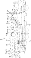
도 1은 콘크리트 분배 붐을 갖는 차량 콘크리트 펌프의 측면도.
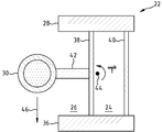
도 2는 콘크리트 전달 도관을 갖는 콘크리트 분배 붐 내의 붐 암을 통한 단면.
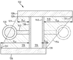
도 3은 크랭크형 섹션을 가지며 콘크리트 전달 도관을 지지하는, 콘크리트 분배 붐용 추가 붐 암의 단면.
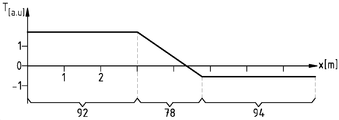
도 4는 콘크리트 전달 도관에 의해 추가 붐 암 내에 형성된 비틀림 하중을 도시하는 도면.
도 5 내지 도 8은 콘크리트 분배 붐에 대한 대안의 구성의 추가 붐 암을 도시하는 도면.
도 9 및 도 10은 콘크리트 분배 붐용 추가 붐 암의 평면도.BRIEF DESCRIPTION OF THE DRAWINGS The present invention will now be described in more detail with reference to a representative embodiment schematically illustrated in the accompanying drawings:
1 is a side view of a vehicle concrete pump having a concrete distribution boom;
2 is a cross-section through a boom arm in a concrete distribution boom having a concrete delivery conduit.
Figure 3 is a section of an additional boom arm for a concrete distribution boom having a crank-shaped section and supporting a concrete delivery conduit.
4 shows a torsional load formed in an additional boom arm by means of a concrete delivery conduit;
Figures 5 to 8 show additional boom arms of an alternative configuration to a concrete distribution boom.
Figures 9 and 10 are plan views of additional boom arms for concrete distribution booms.
도 1에서 차량 콘크리트 펌프(10)는 콘크리트 분배 붐(18)을 지지하는 구조물(14)을 갖는 새시(12)를 포함한다. 콘크리트 분배 붐(18)은 붐 지지대(16)에서 구조물(14) 상에 장착되고 붐 암(22, 22', 22'', 22''')이 수평 회전축 주위에서 이동가능한 회전식 조인트(34, 34', 34'', 34''')를 갖는다. 콘크리트 분배 붐(18)은 회전 커플링(52)과 파이프 커플링(21)에 의해 서로 관절연결방식으로 연결되는 파이프 세그먼트(30) 및 파이프 굽힘부(50)를 갖는 콘크리트 전달 도관(20)을 포함하도록 형성된다. 1, a
도 2는 도 1에서의 선(II-II)을 따라 붐 암(22)의 단면을 도시한다. 붐 암(22)은 종방향으로 연장되는 원주방향의 개방 중공 챔버(26) 및 폐쇄되고 신장된 중공 챔버(24)를 갖는 중공 챔버 프로파일을 갖는다. 붐 암(22)의 중공 챔버 프로파일은 하부 플랜지(36) 및 상부 플랜지(28)를 갖는 박스형태이다. 박스는 제1 측면 벽(38)과 제2 측면 벽(40)을 갖는다. 제1 측면 벽(38)은 중공 챔버 프로파일의 파티션이다. 상부 플랜지(28)와 하부 플랜지(36)는 서로 평행하고, 제1 측면 벽 및/또는 제2 측면 벽은 상부 플랜지 및/또는 하부 플랜지에 수직하다. 제1 측면 벽(38)은 상부 플랜지(28)와 하부 플랜지(36)에 대해 후방에 배치된다.Fig. 2 shows a section of the
붐 암(22)과 연계되는 콘크리트 분배 붐(18) 내의 파이프 세그먼트(30)는 이의 개구 측면에서 중공 챔버(26)의 외측에 배열된다. 또한, 그러나 기본적으로 콘크리트 전달 도관(20)의 파이프 세그먼트(30)는 개방 중공 챔버(26) 내에 부분적으로 배열되거나 또는 심지어 전체적으로 배열될 수 있다.The
파이프 세그먼트(30)는 제1 측면 벽(38)에 고정되고 중공 챔버(26) 내로 돌출되는 파이프 브래킷(42)에 의해 붐 암(22) 상에 고정된다. 이 수단에 의해, 화살표(46)에 따라 작용하는 콘크리트 전달 도관(20)의 하중에 의해 파이프 브래킷(42)을 통해 붐 암(22) 내로 도입되는 비틀림 모멘트가 최소화될 수 있다. 도 1에 도시된 콘크리트 분배 붐(18) 내의 붐 암(22', 22'', 22''')은 또한 붐 암(22)의 구성에 대응하는 구성을 갖는다.The
도 3은 콘크리트 전달 도관(80)을 포함한 콘크리트 붐배 붐용 추가 붐 암(62)의 섹션을 도시한다. 붐 암(62)은 종방향으로 연장되는 2개의 원주방향 개방 중공 챔버(66, 68)를 포함하고 밀폐되고 신장된 중공 챔버(64)를 갖는 중공 챔버 프로파일을 갖는다. 붐 암(62)의 중공 챔버 프로파일은 또한 하부 플랜지(72) 및 상부 플랜지(70)를 갖는 박스 형태이다. 박스는 제1 측면 벽(74)과 제2 측면 벽(76)을 갖는다. 2개의 측면 벽(74, 76)은 중공 챔버 프로파일 내의 파티션이다. 상부 플랜지(28)와 하부 플랜지(36)는 서로 평행하고, 제1 측면 벽(74) 및/또는 제2 측면 벽(76)은 상부 플랜지(70)와 하부 플랜지(72)에 대해 수직이다. 그러나, 본 발명에 따른 붐 암의 경우에, 또한 원뿔형으로 서로 테이퍼지는 상부 플랜지와 하부 플랜지를 제공할 수 있다.3 shows a section of an
도 1 및 도 2에 도시된 붐 암(22)과 대조적으로, 붐 암(62)은 크랭크형 섹션(78)을 갖는다. 콘크리트 전달 도관(80)은 제2 측면 벽(76) 상에서 파이프 브래킷(86, 88)에 의해 제1 측면 벽(74) 상에서 파이프 브래킷(82, 84)에 의해 붐 암(62)에 고정된다. 크랭크형 섹션(78)에서, 콘크리트 전달 도관은 제1 측면 벽(74), 밀폐된 중공 챔버(64) 및 제2 측면 벽(76)을 통하여 붐 암(62)의 마주보는 측면으로 붐 암(62)의 일 측면으로부터 유도된다. 이 섹션(92)에서, 제2 측면 벽(76)으로부터 제1 측면 벽(74)의 간격(A)은 일정하다. 섹션(78)에서, 제1 측면 벽(74)과 제2 측면 벽(76) 사이의 간격은 감소된다. 섹션(94)에서, 제2 측면 벽(76)으로부터 제1 측면 벽(74)의 간격(B)은 B < A으로 정해진다. 이 수단에 따라, 붐 암 크로스 섹션의 비틀림 저항이 이의 하중에 대해 붐 암(62)을 가로질러 적합해진다.In contrast to the
도 4는 붐 암 섹션(92) 내에서 상부 및 하부 플랜지(70, 72)의 영역의 공통 중심의 선(90)에 대한 콘크리트 전달 도관(80)의 하중에 의해 붐 암(62) 내로 유도되는 비틀림 하중(T)을 도시한다. 콘크리트 전달 도관(800이 붐 암(62)의 측면 벽(74, 76)을 통하여 유도됨에 따라, 크랭크형 섹션(78) 이후에 붐 암(62) 내로 유도되는 비틀림 모멘트(T)는 크랭크형 섹션(78) 이전에 붐 암(62) 내로 유도되는 비틀림 모멘트를 적어도 부분적으로 보상한다.4 is directed into the
붐 암(62)의 경우에, 측면 벽(74, 76)은 부착 구조물에 의해 하부 플랜지(72)와 상부 플랜지(70)에 대한 부착을 위해 설계된다. 상기 부착 구조물은 측면 벽(74, 76)의 후방(set back) 위치에서 상부 플랜지 및 하부 플랜지(70, 72)에 대한 고품질 연결이 가능하도록 설계된다. 그 뒤에, 측면 벽(74, 76)의 섹션은 용접 또는 스크류 연결부에 의해 상기 부착 구조물에 고정된다.In the case of the
도 5는 도 2에 대응하는 단면에서 콘크리트 분배 붐에 대해 붐 암(22)에 대해 대안으로 구성되는 추가 붐 암(122)을 도시한다.Fig. 5 shows an
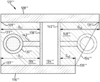
붐 암(122)은 또한 종방향으로 연장되는 원심방향 개방 중공 챔버(126) 및 밀폐된 신장된 중공 챔버(124)를 갖는 중공 챔버 프로파일을 갖는다. 붐 암(122)의 중공 챔버 프로파일은 하부 플랜지(136)와 상부 플랜지(128)를 갖는 박스 형태이다. 박스는 제1 측면 벽(138)과 제2 측면 벽(140)을 갖는다.The
상부 플랜지(128)와 하부 플랜지(136)는 서로 평행하고, 제1 측면 벽 및/또는 제2 측면 벽(138, 140)은 상부 플랜지 및/또는 하부 플랜지에 수직이다. 이 경우에, 제1 측면 벽(138)은 하부 플랜지(136)에 대해 후방에 배치되고, 제1 측면 벽(138)의 측면 상에서 플랜지 에지(137)로부터 간격(DU1)을 갖는다. 역으로, 제1 측면 벽(138)의 측면에서 상부 플랜지(128)의 플랜지 에지(129)는 간격(DO1 < DU1)을 갖는다.The
제1 측면 벽(138)은 중공 챔버 프로파일 내의 파티션이다. 제2 측면 벽(140)은 또한 중공 챔버 프로파일 내의 파티션이다. 제2 측면 벽(140)은 상부 플랜지(128)에 대해 후방에 배치되고, 제1 측면 벽(138)의 측면 상에서 플랜지 에지(131)로부터 간격(DO2)을 갖는다. 대조적으로, 제2 측면 벽(140)의 측면 상에서 하부 플랜지(136)의 플랜지 에지(139)는 간격(DU2 < DO2)을 갖는다.The
제1 측면 벽(138)과 함께 상부 플랜지(128)와 하부 플랜지(136)는 볼록 사다리꼴의 형태인 단면(127)을 갖는 원주방향으로 개방된 중공 챔버(128)를 형성한다. 제2 측면 벽(140)과 함께, 상부 플랜지(128)와 하부 플랜지(136)는 볼록한 사다리꼴의 형태인 단면(154)을 갖는 추가 중공 챔버(148)를 형성하고, 상기 중공 챔버는 원주방향으로 개방된다.The
콘크리트 분배 붐(118) 내에서 콘크리트 전달 도관의 붐 암(122)과 연계된 파이프 세그먼트(130)는 이의 개구 측면 상에서 중공 챔버(126) 외측에 배열되고, 하나 이상의 파이프 브래킷(142)에 의해 제1 측면 벽(138)에 고정된다. 그러나, 또한 콘크리트 전달 도관의 파이프 세그먼트(130)는 개방 중공 챔버(126) 내에 부분적으로 또는 전체적으로 배열될 수 있다. 게다가, 콘크리트 전달 도관의 파이프 세그먼트는 특히 원주방향 개방 중공 챔버(148) 내에서 또는 내에서 부분적으로 또는 외측에서 붐 암(122)의 원주방향 개방 중공 챔버(148)의 측면 상에 배열될 수 있다.The
게다가, 붐 암의 추가 대안의 실시 형태에서, 제1 측면 벽(138)은 상부 플랜지(128)와 동일 높이에 있을 수 있거나, 또는 제2 측면 벽(140)은 하부 플랜지(136)와 동일 높이에 있을 수 있다. 이 경우에, 원주방향 개방 중공 챔버(126)의 단면(127)이 직각 삼각형의 형태를 갖는다. 대응 조건이 원주방향 개방 중공 챔버(148)에 적용된다.In addition, in a further alternative embodiment of the boom arm, the
도 6 내지 도 8은 도 2에 대응하는 단면 내에서 콘크리트 분배 붐에 대해 붐 암(22)에 대한 대안의 구성의 추가 붐 암(122', 122'', 122''')을 도시한다. 이 경우에, 기능이 서로 대응하는 요소가 동일한 도면부호를 사용하여 도 5 내지 도 9에 도시된다.Figs. 6-8 illustrate an
도 6에 도시된 붐 암(122')의 경우에, 상부 플랜지(128')와 하부 플랜지(136')가 중공 챔버(124)의 대칭 축(155')에 대해 대칭을 이루어 배치된다. 즉, 제1 측면 벽(138')으로부터 상부 플랜지(128')의 플랜지 에지(129')의 간격(DO1)과 하부 플랜지(136')의 플랜지 에지(137')의 간격(DU1) 그리고 제1 측면 벽(138')으로부터 상부 플랜지(128')의 플랜지 에지(129')의 간격(DO2)과 하부 플랜지(136')의 플랜지 에지(137')의 간격(DU2)의 경우, 다음이 적용된다: DO1 = DO2 > DU1 = DU2.In the case of the boom arm 122 'shown in FIG. 6, the upper flange 128' and the lower flange 136 'are disposed symmetrically about the symmetry axis 155' of the
도 7에 도시된 붐 암(122")의 경우, 상부 플랜지(128")의 플랜지 에지(129")와 하부 플랜지(136")의 플랜지 에지(137")는 제1 측면 벽(138')으로부터 간격(DU1 > DO1)을 갖는다. 하부 플랜지(136")의 플랜지 에지(139")와 상부 플랜지의 플랜지 에지(131'')는 이 경우에 제2 측면 벽(140")으로부터 간격(DU2 > DO2)을 갖는다. 이 경우에, DO1 = DO2 < DU1 = DU2이다.In the case of the
도 8에 도시된 붐 암(122''')은 이 내에 배열된 콘크리트 전달 도관의 파이프 세그먼트(130''')를 갖는 원주방향으로 개방된 중공 챔버(126"')를 갖는다. 붐 암(122"')의 경우, 상부 플랜지의 플랜지 에지(129"')와 하부 플랜지(136"')의 플랜지 에지(137"')는 제1 측면 벽(138"')으로부터 간격(DU1 = DO1)을 갖는다. 상부 플랜지의 플랜지 에지(129"')와 하부 플랜지(136"')의 플랜지 에지(137"')는 이 경우에 제2 측면 벽(140"')으로부터 간격(DU2 < DO2)을 갖는다.The boom arm 122 '''shown in FIG. 8 has a circumferentially open hollow chamber 126''' having a pipe segment 130 '''of a concrete delivery conduit arranged therein. The
도 9는 제1 및 제2 측면 벽(238, 240)과 원주방향 개방 중공 챔버를 갖는 박스 형태의 중공 챔버 프로파일을 가지며, 도 2에서 붐 암(22)에 대해 대안의 구성인 추가 붐 암(222)을 도시한다. 붐 암(222)의 경우에, 상부 플랜지의 플랜지 에지(237)는 종방향에 걸쳐 값(DO1 (1), DO1 (2), DO1 (3))에 대응하는 제1 측면 벽(238)으로부터 가변 간격(DO1)을 갖는다. 제2 측면 벽(240)으로부터 상부 플랜지의 플랜지 에지(231)의 간격이 이 경우에 종방향에 걸쳐 일정하다.Figure 9 shows an additional boom arm (24) having a hollow chamber profile in the form of a box having first and second side walls (238, 240) and a circumferentially open hollow chamber, 222, respectively. In the case of the
붐 암(222)의 본 발명에 따른 대안의 실시 형태에서, 또한 제1 측면 벽(238)의 측면 상에서 하부 플랜지의 플랜지 에지의 간격(DU1) 또는 단지 하부 플랜지의 플랜지 에지의 간격(DU1)은 붐 암(222)의 종방향을 따라 상이한 값을 취할 수 있다.In the embodiment of the alternatives according to the invention of the
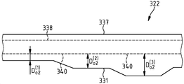
도 10에 도시된 붐 암(322)의 경우에, 제1 및 제2 측면 벽(338, 340)과 함께 상부 플랜지와 하부 플랜지는 박스형의 중공 챔버 프로파일을 형성하고, 이 경우에 제2 측면 벽(340)으로의 상부 플랜지의 플랜지 에지(331)로부터의 간격(DU2 또는 DO2)이 붐 암(322)의 종방향에 걸쳐 상이한 값(DO2 (1), DO2 (2), DO2 (3)...)을 취한다. 이경우에, 붐 암(322)의 본 발명에 따른 대안의 실시 형태에서, 제1 측면 벽(338)의 측면 상에서 상부 플랜지 또는 하부 플랜지의 플랜지 에지(337)의 간격(DU1 또는 DO1), 제2 측면 벽(340)의 측면 상에서 하부 플랜지의 플랜지 에지(331)의 간격(DU1) 또는 단지 하부 플랜지의 플랜지 에지의 간격(DU1)은 붐 암(322)의 종방향을 따라 상이한 값을 취할 수 있다.In the case of the
도 5 내지 도 10에 따라 전술된 콘크리트 분배 붐 내의 붐 암의 실시 형태에 따라서, 파이프 브래킷에 의해 콘크리트 전달 도관의 하중에 의해 붐 암 내로 유입되는 비틀림 모멘트가 낮아질 수 있다.According to the embodiment of the boom arm in the concrete distribution boom described above according to Figs. 5 to 10, the torsional moment introduced into the boom arm by the load of the concrete conveying conduit by the pipe bracket can be lowered.
전술된 붐 암의 중공 챔버 프로파일은 금속뿐만 아니라 섬유 복합 플라스틱으로 구성될 수 있다.The hollow chamber profile of the above-mentioned boom arm can be composed of a metal composite as well as a metal composite.
또한, 본 발명은 전술된 예시적인 실시 형태의 상이한 특징의 조합으로부터 유발되는 구체적인 분배 붐의 추가 변형 및 개선점을 포함한다.The present invention also includes further modifications and improvements to the specific distribution boom resulting from the combination of the different features of the above described exemplary embodiments.
요약하면, 다음과 같다: 고정식 및 이동식 콘크리트 펌프용 콘크리트 분배 붐(18)은 조인트(34)에서 서로 연결되는 다수의 붐 암(22)을 가지며 개별 붐 암(22)에 체결되고 이를 따라 유도되는 회전식 커플링(52) 및 파이프 굽힘부(50)에 의해 바람직하게는 서로 관절 연결되는 다수의 파이프 세그먼트(30)로 구성되는 콘크리트 전달 도관(20)을 갖는다. 하나 이상의 붐 암(22)은 파티션(40)에 의해 서로 분리되는 2개 이상의 중공 챔버(24, 26)를 갖는 중공 챔버 프로파일을 가지며 이들 중 하나의 챔버(24)는 밀폐되고 다른 하나의 챔버(26)는 원주 방향으로 개방된다. 이 경우에, 각각의 붐 암(22)과 연계된 파이프 세그먼트(30)는 부분적으로 개방 중공 챔버(26) 내에서 또는 이 내에서 개구 측면 상에 배열된다.In summary:
10 차량 콘크리트 펌프
12 새시
14 구조물
16 붐 지지대
18 콘크리트 분배 붐
20 콘크리트 전달 도관
22, 22', 22'', 22''' 붐 암
24 밀폐된 중공 챔버
26 원주방향으로 개방된 중공 챔버
28 상부 플랜지
30 파이프 세그먼트
32 파이프 커플링
34, 34', 34'', 34''' 회전식 조인트
36 하부 플랜지
38 제1 측면 벽
40 제2 측면 벽
42 파이프 브래킷
44 라인
46 화살표
50 파이프 굽힙부
52 회전식 커플링
62 붐 암
64 중공 챔버
66 중공 챔버
68 중공 챔버
70 상부 플랜지
72 하부 플랜지
74 제1 측면 벽
76 제2 측면 벽
78 크랭크형 섹션
80 콘크리트 전달 도관
82 파이프 브래킷
84 파이프 브래킷
86 파이프 브래킷
88 파이프 브래킷
90 라인
92 섹션
94 섹션
118 콘크리트 분배 붐
122, 122', 122'', 122''' 붐 암
124, 124', 124'', 124''' 밀폐된 신장 중공 챔버
126, 126', 126'', 126''' 개방된 중공 챔버
127, 127', 127'', 127''' 단면
128, 128', 128'', 128''' 상부 플랜지
129, 129', 129'', 129''' 상부 플랜지의 플랜지 에지
130, 130', 130'', 130''' 파이프 세그먼트
131, 131', 131'', 131''' 플랜지 에지
136, 136', 136'', 136''' 하부 플랜지
137, 137', 137'', 137''' 플랜지 에지
138, 138', 138'', 138''' 제1 측면 벽
139, 139', 139'', 139''' 플랜지 에지
140, 140', 140'', 140''' 제2 측면 벽
142, 142', 142'', 142''' 파이프 브래킷
148, 148', 148'', 148''' 원주방향 개방 중공 챔버
154, 154', 154'', 154''' 단면
155', 155'' 대칭 축
222, 322 붐 암
231, 331 플랜지 에지
237, 337 플랜지 에지
238, 338 제1 측면 벽
240, 340 제2 측면 벽
DU1 간격
DU2 간격
DO1 간격
DO2 간격10 Vehicle Concrete Pumps
12 Chassis
14 Structure
16 boom support
18 Concrete distribution boom
20 Concrete delivery conduit
22, 22 ', 22'',22'''
24 closed hollow chamber
26 Circumferentially open hollow chamber
28 Upper flange
30 pipe segments
32 pipe coupling
34, 34 ', 34'',34'''
36 Lower flange
38 first side wall
40 second side wall
42 Pipe bracket
44 lines
46 Arrow
50 Pipe heel
52 Rotary coupling
62 Boom arm
64 hollow chamber
66 hollow chamber
68 hollow chamber
70 Upper flange
72 Lower flange
74 first side wall
76 Second side wall
78 Crank section
80 Concrete delivery conduit
82 Pipe bracket
84 Pipe bracket
86 Pipe bracket
88 Pipe bracket
90 lines
92 sections
94 sections
118 Concrete distribution boom
122, 122 ', 122'',122'''
124, 124 ', 124'',124'''
126, 126 ', 126'',126'''
127, 127 ', 127'',127'''
128, 128 ', 128'',128'''
129, 129 ', 129'',129''' flange edge of the upper flange
130, 130 ', 130'',130'''
131, 131 ', 131'',131'''
136, 136 ', 136'',136'''
137, 137 ', 137'',137'''
138, 138 ', 138'',138'''
139, 139 ', 139'',139'''
140, 140 ', 140'',140'''
142, 142 ', 142'',142''' pipe bracket
148, 148 ', 148'',148''' circumferentially open hollow chambers
154, 154 ', 154'',154'''
155 ', 155''symmetrical axis
222, 322 boom arm
231, 331 flange edge
237, 337 flange edge
238, 338 first side wall
240, 340 second side wall
D U1 Interval
D U2 interval
D O1 interval
D O2 interval
Claims (15)
하나 이상의 붐 암(22)이 파티션(38)에 의해 서로 분리되는 2개 이상의 중공 챔버(24, 26)를 포함한 중공 챔버 프로파일을 가지며, 상기 챔버들 중 하나의 중공 챔버(24)는 밀폐되고 다른 하나의 중공 챔버(26)는 원주방향으로 개방되며, 각각의 붐 암(22)과 연계된 파이프 세그먼트(30)는 개방된 중공 챔버(26) 내에서 부분적으로 또는 전체적으로 개구 측면 외측에 배열되는 콘크리트 분배 붐.A plurality of boom arms 22 connected to each other at a joint 34 and articulated to each other by a pipe bend 50 and fastened to and guided along the individual boom arm 22 and provided with a rotary coupling 52 and a plurality A concrete distribution boom (18) for a stationary and mobile concrete pump having a concrete delivery conduit (20) consisting of a pipe segment (30)
Wherein one or more boom arms (22) have a hollow chamber profile including two or more hollow chambers (24, 26) separated from one another by a partition (38), one of the chambers One hollow chamber 26 is opened in the circumferential direction and the pipe segments 30 associated with each boom arm 22 are arranged in the open hollow chamber 26, Distribution boom.
Applications Claiming Priority (3)
| Application Number | Priority Date | Filing Date | Title |
|---|---|---|---|
| DE102012213729.7 | 2012-08-02 | ||
| DE102012213729.7A DE102012213729A1 (en) | 2012-08-02 | 2012-08-02 | Concrete distributor boom for concrete pumps |
| PCT/EP2013/065468 WO2014019885A1 (en) | 2012-08-02 | 2013-07-23 | Concrete dispensing boom for concrete pumps |
Publications (1)
| Publication Number | Publication Date |
|---|---|
| KR20150033720A true KR20150033720A (en) | 2015-04-01 |
Family
ID=48808378
Family Applications (1)
| Application Number | Title | Priority Date | Filing Date |
|---|---|---|---|
| KR1020157003234A KR20150033720A (en) | 2012-08-02 | 2013-07-23 | Concrete dispensing boom for concrete pumps |
Country Status (8)
| Country | Link |
|---|---|
| US (1) | US9512628B2 (en) |
| EP (1) | EP2880229B1 (en) |
| JP (1) | JP6031605B2 (en) |
| KR (1) | KR20150033720A (en) |
| CN (1) | CN104641058B (en) |
| BR (1) | BR112015001930A2 (en) |
| DE (1) | DE102012213729A1 (en) |
| WO (1) | WO2014019885A1 (en) |
Families Citing this family (4)
| Publication number | Priority date | Publication date | Assignee | Title |
|---|---|---|---|---|
| DE102014200396A1 (en) * | 2014-01-13 | 2015-07-30 | Putzmeister Engineering Gmbh | Truck-mounted concrete pump and protection circuit for it |
| DE102014215947A1 (en) | 2014-08-12 | 2016-03-03 | Putzmeister Engineering Gmbh | hollow body |
| DE102018204079A1 (en) * | 2018-03-16 | 2019-09-19 | Putzmeister Engineering Gmbh | Truck-mounted concrete pump and method for the stability-relevant control of a truck-mounted concrete pump |
| CN114517580B (en) * | 2020-11-20 | 2024-03-08 | 三一汽车制造有限公司 | Arm support device and working vehicle |
Family Cites Families (12)
| Publication number | Priority date | Publication date | Assignee | Title |
|---|---|---|---|---|
| IT946523B (en) * | 1972-01-13 | 1973-05-21 | Worthington Soc Italiana Pompe | TRUCK PUMPING COMPLEX FOR THE CASTING OF CONCRETE IN PARTICULAR PARTS IN THE CONSTRUCTION OF GALLE RIE AND PROCEDURE FOR CASTING THE CAP OF PARTICOLARMEN T TUNNELS THAT CAN BE USED THROUGH THIS COMPLEX |
| US3942554A (en) * | 1974-04-19 | 1976-03-09 | Werner Corporation | Extendable crane with folding conduit |
| DE3013450A1 (en) * | 1980-04-05 | 1981-10-08 | Stetter Gmbh, 8940 Memmingen | DISTRIBUTION POLE OF A CONCRETE PUMP |
| US4828033A (en) * | 1981-06-30 | 1989-05-09 | Dowell Schlumberger Incorporated | Apparatus and method for treatment of wells |
| US4519768A (en) * | 1982-10-29 | 1985-05-28 | Takenaka Komuten Co., Ltd. | Apparatus for horizontally casting concrete |
| DE19641789C1 (en) * | 1996-10-10 | 1998-07-16 | Korthaus Ernst | Concrete distribution system for ready-mixed concrete |
| DE19644410A1 (en) | 1996-10-25 | 1998-04-30 | Putzmeister Ag | Concrete placing boom for concrete pumps |
| JP3678592B2 (en) * | 1998-11-12 | 2005-08-03 | 極東開発工業株式会社 | Telescopic cylinder mounting structure in boom device |
| US6786233B1 (en) * | 2001-02-23 | 2004-09-07 | Schwing America, Inc. | Boom utilizing composite material construction |
| DE102006040092A1 (en) * | 2006-08-28 | 2008-03-06 | Putzmeister Ag | Arrangement for conveying concrete with height-adjustable concrete boom |
| ITUD20070169A1 (en) * | 2007-09-19 | 2009-03-20 | Cifa Spa | PROCEDURE FOR THE CONSTRUCTION OF A CONCRETE DISTRIBUTION ARM, AND ARM OBTAINED SO |
| CN201321722Y (en) * | 2008-12-23 | 2009-10-07 | 赵光辉 | Novel concrete material distributing rod |
-
2012
- 2012-08-02 DE DE102012213729.7A patent/DE102012213729A1/en not_active Withdrawn
-
2013
- 2013-07-23 WO PCT/EP2013/065468 patent/WO2014019885A1/en active Application Filing
- 2013-07-23 KR KR1020157003234A patent/KR20150033720A/en not_active Application Discontinuation
- 2013-07-23 JP JP2015524715A patent/JP6031605B2/en not_active Expired - Fee Related
- 2013-07-23 CN CN201380048186.1A patent/CN104641058B/en not_active Expired - Fee Related
- 2013-07-23 BR BR112015001930A patent/BR112015001930A2/en not_active IP Right Cessation
- 2013-07-23 EP EP13739458.1A patent/EP2880229B1/en not_active Not-in-force
-
2015
- 2015-01-30 US US14/610,654 patent/US9512628B2/en not_active Expired - Fee Related
Also Published As
| Publication number | Publication date |
|---|---|
| EP2880229B1 (en) | 2016-09-07 |
| CN104641058B (en) | 2016-09-28 |
| BR112015001930A2 (en) | 2017-07-04 |
| EP2880229A1 (en) | 2015-06-10 |
| DE102012213729A1 (en) | 2014-02-06 |
| JP6031605B2 (en) | 2016-11-24 |
| US20150136266A1 (en) | 2015-05-21 |
| US9512628B2 (en) | 2016-12-06 |
| CN104641058A (en) | 2015-05-20 |
| WO2014019885A1 (en) | 2014-02-06 |
| JP2015527510A (en) | 2015-09-17 |
Similar Documents
| Publication | Publication Date | Title |
|---|---|---|
| KR20150033720A (en) | Concrete dispensing boom for concrete pumps | |
| CN106164394A (en) | Screen device | |
| KR101669441B1 (en) | Hinge joint of steel pipe truss structure, steel pipe truss structure therewith and the steel pipe truss structure construction method therefor | |
| CN104271855B (en) | The concrete pump of wheeled | |
| ITMI992674A1 (en) | SUPPORT FRAME FOR AN ELECTRICAL CABINET AND ITS CABINET | |
| US20120175462A1 (en) | Aircraft engine mounting structure, assembly comprising this structure and associated aircraft | |
| EP2211000B1 (en) | Form panel for formworking a concrete wall | |
| RU2589813C2 (en) | Bracket for fuel filter | |
| US8328142B2 (en) | Aileron actuator bracket | |
| CN109505319A (en) | Excavator boom and excavator | |
| CN110107134A (en) | The hinged concrete frame of assembled-buckling restrained brace structure | |
| CN109371884A (en) | The rubbish box assembly of sweeper and sweeper with it | |
| KR100961225B1 (en) | Composite Concrete Plate Enclosing Fiber Reinforced Plastics Deck | |
| EP1630075A1 (en) | Vehicle body having improved dynamic behaviour | |
| CN106284062A (en) | Bridge telescopic unit component and bridge extension joint | |
| FR3105777B1 (en) | Ventral beam in the shape of a tuning fork for an aircraft with a ventral hold | |
| CN109505318A (en) | Excavator boom and excavator | |
| CN107109853B (en) | Column arm and concrete distribution column | |
| AU2015266275B2 (en) | Mounting device | |
| CN106828090B (en) | Transmission shaft mounting structure | |
| CN218714071U (en) | Overlength concrete wall structure | |
| CN110438885A (en) | A kind of bridge tunnel supporting member | |
| CN205822473U (en) | I-steel high intensity node structure | |
| ITMI20100690A1 (en) | IMPROVED TYPE STRUCTURE FOR THE GROUND SUPPORT OF PHOTOVOLTAIC MODULES AND PHOTOVOLTAIC PLANT PROVIDED WITH THIS STRUCTURE | |
| CN210561710U (en) | Bridge expansion joint structure |
Legal Events
| Date | Code | Title | Description |
|---|---|---|---|
| E902 | Notification of reason for refusal | ||
| E902 | Notification of reason for refusal | ||
| E601 | Decision to refuse application |