KR20140145714A - rolling type sweeping device - Google Patents
rolling type sweeping device Download PDFInfo
- Publication number
- KR20140145714A KR20140145714A KR1020130068173A KR20130068173A KR20140145714A KR 20140145714 A KR20140145714 A KR 20140145714A KR 1020130068173 A KR1020130068173 A KR 1020130068173A KR 20130068173 A KR20130068173 A KR 20130068173A KR 20140145714 A KR20140145714 A KR 20140145714A
- Authority
- KR
- South Korea
- Prior art keywords
- mop
- water
- cleaning
- garbage
- gear
- Prior art date
Links
Images


Classifications
-
- A—HUMAN NECESSITIES
- A47—FURNITURE; DOMESTIC ARTICLES OR APPLIANCES; COFFEE MILLS; SPICE MILLS; SUCTION CLEANERS IN GENERAL
- A47L—DOMESTIC WASHING OR CLEANING; SUCTION CLEANERS IN GENERAL
- A47L11/00—Machines for cleaning floors, carpets, furniture, walls, or wall coverings
- A47L11/02—Floor surfacing or polishing machines
- A47L11/04—Floor surfacing or polishing machines hand-driven
- A47L11/08—Floor surfacing or polishing machines hand-driven with rotating tools
-
- A—HUMAN NECESSITIES
- A47—FURNITURE; DOMESTIC ARTICLES OR APPLIANCES; COFFEE MILLS; SPICE MILLS; SUCTION CLEANERS IN GENERAL
- A47L—DOMESTIC WASHING OR CLEANING; SUCTION CLEANERS IN GENERAL
- A47L11/00—Machines for cleaning floors, carpets, furniture, walls, or wall coverings
- A47L11/26—Floor-scrubbing machines, hand-driven
-
- A—HUMAN NECESSITIES
- A47—FURNITURE; DOMESTIC ARTICLES OR APPLIANCES; COFFEE MILLS; SPICE MILLS; SUCTION CLEANERS IN GENERAL
- A47L—DOMESTIC WASHING OR CLEANING; SUCTION CLEANERS IN GENERAL
- A47L11/00—Machines for cleaning floors, carpets, furniture, walls, or wall coverings
- A47L11/40—Parts or details of machines not provided for in groups A47L11/02 - A47L11/38, or not restricted to one of these groups, e.g. handles, arrangements of switches, skirts, buffers, levers
- A47L11/4013—Contaminants collecting devices, i.e. hoppers, tanks or the like
-
- A—HUMAN NECESSITIES
- A47—FURNITURE; DOMESTIC ARTICLES OR APPLIANCES; COFFEE MILLS; SPICE MILLS; SUCTION CLEANERS IN GENERAL
- A47L—DOMESTIC WASHING OR CLEANING; SUCTION CLEANERS IN GENERAL
- A47L11/00—Machines for cleaning floors, carpets, furniture, walls, or wall coverings
- A47L11/40—Parts or details of machines not provided for in groups A47L11/02 - A47L11/38, or not restricted to one of these groups, e.g. handles, arrangements of switches, skirts, buffers, levers
- A47L11/4036—Parts or details of the surface treating tools
- A47L11/4041—Roll shaped surface treating tools
-
- A—HUMAN NECESSITIES
- A47—FURNITURE; DOMESTIC ARTICLES OR APPLIANCES; COFFEE MILLS; SPICE MILLS; SUCTION CLEANERS IN GENERAL
- A47L—DOMESTIC WASHING OR CLEANING; SUCTION CLEANERS IN GENERAL
- A47L11/00—Machines for cleaning floors, carpets, furniture, walls, or wall coverings
- A47L11/40—Parts or details of machines not provided for in groups A47L11/02 - A47L11/38, or not restricted to one of these groups, e.g. handles, arrangements of switches, skirts, buffers, levers
- A47L11/4052—Movement of the tools or the like perpendicular to the cleaning surface
- A47L11/4058—Movement of the tools or the like perpendicular to the cleaning surface for adjusting the height of the tool
-
- A—HUMAN NECESSITIES
- A47—FURNITURE; DOMESTIC ARTICLES OR APPLIANCES; COFFEE MILLS; SPICE MILLS; SUCTION CLEANERS IN GENERAL
- A47L—DOMESTIC WASHING OR CLEANING; SUCTION CLEANERS IN GENERAL
- A47L11/00—Machines for cleaning floors, carpets, furniture, walls, or wall coverings
- A47L11/40—Parts or details of machines not provided for in groups A47L11/02 - A47L11/38, or not restricted to one of these groups, e.g. handles, arrangements of switches, skirts, buffers, levers
- A47L11/4063—Driving means; Transmission means therefor
-
- A—HUMAN NECESSITIES
- A47—FURNITURE; DOMESTIC ARTICLES OR APPLIANCES; COFFEE MILLS; SPICE MILLS; SUCTION CLEANERS IN GENERAL
- A47L—DOMESTIC WASHING OR CLEANING; SUCTION CLEANERS IN GENERAL
- A47L11/00—Machines for cleaning floors, carpets, furniture, walls, or wall coverings
- A47L11/40—Parts or details of machines not provided for in groups A47L11/02 - A47L11/38, or not restricted to one of these groups, e.g. handles, arrangements of switches, skirts, buffers, levers
- A47L11/408—Means for supplying cleaning or surface treating agents
- A47L11/4088—Supply pumps; Spraying devices; Supply conduits
Landscapes
- Cleaning Implements For Floors, Carpets, Furniture, Walls, And The Like (AREA)
Abstract
BACKGROUND OF THE INVENTION 1. Field of the Invention [0001] The present invention relates to a cleaning device, and more particularly, to a cleaning device that rotates a mop (or a broom) attached to a vacuum cleaner when the vacuum cleaner is pushed, collects garbage and automatically collects garbage with a dustbin, A power transmitting portion to which a gear is attached; A dust collecting part consisting of a dustbin which is periodically moved by a cam mounted on a shaft of a gear for rotating the cylindrical mop, and a dust separator; A cleaning unit that adjusts the height of the mop rotating shaft so as to maintain a constant adhesion between the mop and the cleaning floor; A dewatering unit for dewatering the water absorbed in the mop through cleaning and collecting the dewatered water in the dust collecting unit; And a water tub for supplying water to the mop and adjusting the amount of the water and cleaning the water. Thus, when the cleaning device is pushed, it is possible to automatically collect the trash from the floor and collect the water in the trash can, Effect.
Description
BACKGROUND OF THE INVENTION 1. Field of the Invention [0001] The present invention relates to a cleaning apparatus, and more particularly, to a cleaning apparatus that rotates a mop (or a broom) through a rotating force of a wheel attached to the cleaning apparatus to collect garbage and automatically collects the garbage .
Generally, cleaners can be classified as dry cleaning and water cleaning. They can be divided into manpower-based cleaners and power-driven cleaners.
In the case of using rain and a dustpan to collect garbage during dry cleaning, there is a disadvantage that it is difficult to effectively clean fine garbage by combing when dusts are blown in the course of combing or when there is water on the floor. In addition, there is an inconvenience that the rain and the dustpan must be separately used.
In the case of dry cleaning, there is a method of cleaning the floor garbage using a mop using microfine dust or static electricity. In this case, if there is water on the floor, the effect of dust collection is remarkably reduced. Garbage such as glass pieces and large sands of eggs are continuously pushed out without being collected, causing scratches on the floor, and garbage must be collected through separate combing or the like. Furthermore, it is difficult to reuse the used mop, and there is a disadvantage in that additional costs are incurred.
There is also a method of collecting garbage on the surface through a vacuum cleaner which is wrapped around an adhesive tape. If there is water on the surface, it is not possible to use it. It is difficult to clean it for a wide place and it is disadvantage
When cleaning the water, it is easy to collect the collected garbage along with the water cleaning by using the hand rag, but it is easy to collect large area, and it is very difficult to clean the large area. On the other hand, when using a mop made of paper or a chemical fiber bundle, garbage such as a plastic piece, a metal piece, a glass piece, and a large sand is continuously pushed out without being collected, thereby causing scratches on the floor, It is necessary to collect garbage.
In the case of a vacuum cleaner using electricity, the preparation process such as removing the vacuum cleaner, removing the electric wire, plugging in the power supply and connecting the cleaning hose is troublesome for the cleaning, and is generally heavy, There is a disadvantage that it has no effect.
It is an object of the present invention to provide an apparatus for collecting garbage and automatically collecting and collecting garbage into a trash can by cleaning the floor only by pushing the cleaner without using electric power .
It is another object of the present invention to provide a device capable of freely cleaning dry and water, and capable of automatically cleaning and easily dewatering the mop itself
In order to solve the above-mentioned problems, the present invention provides a cleaning apparatus for a wiped rotary type, comprising: a gear mounted between a wheel and a cylindrical mop for reducing or increasing a rotation speed of the cylindrical mop; A power transmission portion which can be changed; The dust catcher provided at the front and back of the cylindrical mop is periodically repetitively pressed and separated from the cylindrical mop by the cam mounted on the rotary shaft of the cylindrical mop to collect the garbage pushed through the mop, A dust collecting part for collecting garbage collected in the dust collecting compartment of the garbage compartment; A cleaning unit for cleaning the mop by detaching the cylindrical mop from the main body and adjusting the height of the cylindrical mop rotating shaft so as to maintain a constant contact force between the mop and the cleaning floor without being influenced by the wear of the mop or the degree of bending of the ground; A dewatering unit for dewatering the water absorbed in the mop through cleaning and collecting the dewatered water in the dust collecting unit; And a water tub for supplying water to the mop, adjusting the amount of the water, and cleaning the water.
The mop sweep type cleaning apparatus using the rotational force of the wheel according to the present invention provides an advantage that the user can collect the collected wastes automatically in the trash can while cleaning the user by pushing the cleaning apparatus.
In addition, when the user pushes the cleaning device, it is possible to easily dewater the dirty water absorbed on the floor absorbed by the mop and the dirty water from the mop, thereby making it possible to freely clean the water as well as the dry cleaning.
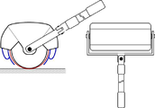
Figs. 1A and 1B are external views of a cleaning device for a wiper type sweeping device according to an embodiment of the present invention
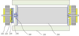
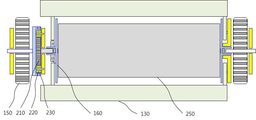
Figs. 2A and 2B are a plan view of a cleaning device for a wet rotary type according to an embodiment of the present invention
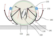
Fig. 3 is a side view of the cleaning device of the wiper type according to the embodiment of the present invention
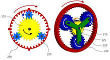
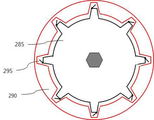
4 is a configuration diagram of a power transmitting portion for transmitting wheel turning force according to an embodiment of the present invention
5 is an exemplary view of a dust collecting part according to an embodiment of the present invention
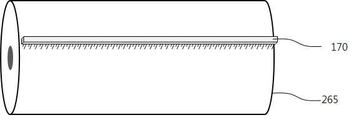
Fig. 6 is an example of a dust separator for removing waste attached to a rag according to an embodiment of the present invention
Fig. 7 is a schematic diagram of a cleaning part according to an embodiment of the present invention
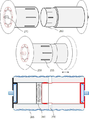
Figs. 8A, 8B and 8C are diagrams showing a configuration of an apparatus for varying the center position of the axis of the wiper rotating body according to the embodiment of the present invention
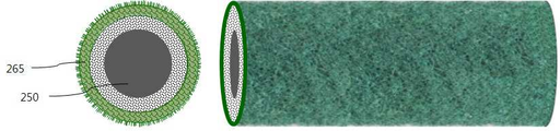
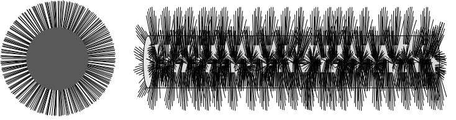
Figs. 9A, 9B and 9C are diagrams showing examples of the kind of mop for each cleaning purpose that can be used for the mop body
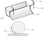
Fig. 10 shows an example of a water receiving part and a dewatering part for water cleaning
Hereinafter, embodiments of the present invention will be described in detail with reference to the accompanying drawings.
Figs. 1A and 1B show an appearance of a cleaning device for a wiped rotary type according to an embodiment of the present invention. The user can adjust the length of the plunger by adjusting the left and right joints so that the plunger can move the
FIG. 2A shows the construction of a wiping-type cleaning apparatus according to an embodiment of the present invention. When the user pushes or pulls the cleaning device, the
When the
A driving method of the cleaning apparatus will be described in detail with reference to FIG. When the
When the dustpan is raised, the mop cleans the floor and collects garbage. When the dustpan is lowered, the surface of the dustpan is brought into close contact with the mop, thereby wiping up the collected garbage. The washed-out waste falls to the
The cycle of raising and lowering the dust pan by the cam can be arbitrarily set according to the diameter of the mop body.
Referring to FIG. 4, the power transmission unit for transmitting the rotational force of the wheel according to the embodiment of the present invention will be described in detail. The
The spur gear and the internal gear of the power transmission unit thus configured are rotated in opposite directions to each other. When the inner diameter of the internal gear is determined, the rotation ratio is determined by the size of the spur gear. To increase the rotation speed of the mop, connect a spur gear to the entire mop and connect the internal gear to the wheel. Conversely, in order to lower the rotation speed of the mop and increase the torque, connect the internal gear to the entire mop and connect the spur gear to the wheel.
Therefore, when the wheel rotates in the clockwise direction, the mop is rotated in the counterclockwise direction and is dragged to increase the friction force with the floor, thereby enhancing the cleaning effect and increasing the effect of collecting the collected garbage to the dustpan.
5 is a configuration diagram showing a configuration of a dust collecting portion according to an embodiment of the present invention. The curvature of the
The jaw on the upper end of the dustpan (130) is directed slightly toward the mop so that the trash conveyed from the mop is concentrated and does not leak downward. When the mop is rotated in the direction of upward movement, the pressure of the mop is applied by the elasticity of the mop, so that the waste is pushed up in close contact with the mop. On the contrary, when the mop is rotated in the downward direction, the residual waste passing through the waste pod So that the waste is separated from the
In addition, the lower end of the
Fig. 6 shows a dust separator for discharging garbage attached to a mop according to an embodiment of the present invention. The
7 shows a cleaning part according to an embodiment of the present invention. The cleaning unit includes the
At this time, in order to easily reduce the length of the mop covering the inside of the
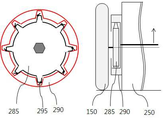
Figs. 8A, 8B and 8C illustrate an apparatus for changing the center position of the axis of the latitudinal rotating body according to the embodiment of the present invention. When the
In order to stably maintain the contact pressure between the mop and the floor, as shown in FIG. 8A, a
8B, the height of the shaft of the
The diameter of the mop wrapped around the mop initially is designed to be larger than the diameter of the wheel so that the pressure applied to the spring between the two mop when the mop touches the ground is greater than between the two teeth located on the bottom, It is preferable to design such that the distance between them is higher.
The
Figs. 9A, 9B and 9C illustrate the kind of mop for each cleaning purpose which can be used for the mop body according to the embodiment of the present invention. 9A is an example in which the bottom surface of a mop surface is made of a sponge layer such as a house floor using a microfiber cloth or a cotton cloth, and is suitable for cleaning fine dust such as dust, hair, and sand. The shaft is changed by the apparatus as shown in Fig. 8A so that the mop itself is made elastic, so that the pressure between the mop and the ground is maintained. FIG. 9B is an example of a preferable mop when cleaning the garbage surface by using a cloth such as a wader having a rough ridge and cleaning the garbage such as a concrete floor with a lot of coarse and thick sand. The inside of the mop is constituted by a sponge layer so that the mop itself is made elastic so that the shaft is changed by the device as shown in Fig. 8A to compensate for maintaining the pressure between the mop and the ground. Figure 9c is an example of a mop suitable for cleaning floors with densely arranged bottoms or streets, such as office carpets, using densely brushed ratios, and by means of the device as in Figure 8a using the elasticity of the brush The shaft is varied to compensate for maintaining the pressure between the mop and the ground.
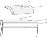
Fig. 10 is a configuration diagram showing the configuration of the water receiving portion and the dewatering portion for cleaning the wet-cloth. The water
110: plunger 120: outer body
130: dustpan 135: spring for returning dustpan position
140: collecting box 145: dustpan cam contact
150: wheel 160: cam
170: a duster 180: a rotary pressure rod for dewatering
190: Water cleaning water tank 195: Water conditioner
210: spur gear 220: pinion gear
225: pinion gear bundle fixing frame 230: internal gear
250: mop rotation total 255: mop rotation total lock
260: The mop all round 265: The mop
270: empty space inside the mop 275:
280: spool spindle spring
285: Power transmission gear 290: Gear motor
295: Spring
Claims (11)
A dust collection unit collecting the garbage through the cylindrical mop and automatically collecting the garbage in the dustpan;
A cleaning unit that varies the height of the wheel shaft and the height of the cylindrical mop shaft;
A dewatering unit for dewatering the water absorbed in the mop and collecting it in the dust collecting unit;
And a water cleaning water tank for cleaning the water.
The power transmission unit connects a spur gear to a wheel and sits the periphery of the spur gear so that two or more pinion gears are rotated at a fixed position. The power transmission unit sits the outer periphery of the pinion gear with the internal gear, So as to rotate in a reverse direction.
The power transmission unit connects the internal gear to the wheel and squeezes the two or more pinion gears to rotate in a fixed position. The rotational force of the wheels causes the cylindrical mop to rotate in the reverse direction To the cleaning device.
The garbage collecting part is configured such that the dust catcher provided on the front, back, front or back of the cylindrical mop is periodically repeatedly attached to and spaced from the cylindrical mop by a cam attached to a gear shaft for rotating the cylindrical mop to collect garbage pushed through the mop And the dust separator is fixed to the upper end of the cylindrical mop to remove the residual garbage attached to the mop to collect it in the dust collecting box of the garbage compartment.
Wherein the lower end of the garbage compartment is curved in a direction opposite to the warp direction of the garbage compartment, and the lower end of the garbage compartment is bent in a direction opposite to the warp direction of the garbage compartment. Typical cleaning device.
Wherein a dust separator having a shape of a compact brush is installed horizontally in accordance with the width of the mop and is always in close contact with the surface of the mop.
Wherein the cleaning unit is capable of removing the cylindrical mop by adjusting the length of the mop rotation body.
A gear attached to the entire mop shaft and a gear transmitting power, and a space is provided between the inner teeth and the outer diameters of the two toothed wheels, and a spring function is provided between the meshing teeth. So as to be variable.
The cleaning device of claim 1, characterized in that the surface of the mop is made of a microfiber cloth or a cotton or brush (brush) form.
Wherein the rotating body in the form of a round rod provided in parallel with the cylindrical mop is in close contact with the mop and rotates together with the mop to apply pressure to draw the water.
Wherein the water tub includes a water tank for storing water at an upper end portion of the cylindrical mop and a water amount controller for controlling the amount of water supplied to the mop.
Priority Applications (1)
| Application Number | Priority Date | Filing Date | Title |
|---|---|---|---|
| KR1020130068173A KR20140145714A (en) | 2013-06-14 | 2013-06-14 | rolling type sweeping device |
Applications Claiming Priority (1)
| Application Number | Priority Date | Filing Date | Title |
|---|---|---|---|
| KR1020130068173A KR20140145714A (en) | 2013-06-14 | 2013-06-14 | rolling type sweeping device |
Publications (1)
| Publication Number | Publication Date |
|---|---|
| KR20140145714A true KR20140145714A (en) | 2014-12-24 |
Family
ID=52675363
Family Applications (1)
| Application Number | Title | Priority Date | Filing Date |
|---|---|---|---|
| KR1020130068173A KR20140145714A (en) | 2013-06-14 | 2013-06-14 | rolling type sweeping device |
Country Status (1)
| Country | Link |
|---|---|
| KR (1) | KR20140145714A (en) |
Cited By (7)
| Publication number | Priority date | Publication date | Assignee | Title |
|---|---|---|---|---|
| CN108451455A (en) * | 2018-03-27 | 2018-08-28 | 佛山市集知汇科技有限公司 | A kind of rolling mop with water squeezing feature |
| CN108478131A (en) * | 2018-03-27 | 2018-09-04 | 佛山市集知汇科技有限公司 | A kind of rolling mop |
| CN111150341A (en) * | 2020-01-22 | 2020-05-15 | 帝舍智能科技(武汉)有限公司 | Cleaning tool |
| CN112873230A (en) * | 2021-01-15 | 2021-06-01 | 于文佳 | Ground cleaning and sterilizing robot based on information technology control |
| CN113584854A (en) * | 2021-06-17 | 2021-11-02 | 姚少辉 | Fabric dust removing device |
| CN114071252A (en) * | 2020-07-29 | 2022-02-18 | 刘情 | Communication intelligence box structure |
| CN115251789A (en) * | 2022-09-20 | 2022-11-01 | 施贝煜 | Sweeping and mopping integrated device |
-
2013
- 2013-06-14 KR KR1020130068173A patent/KR20140145714A/en not_active Application Discontinuation
Cited By (9)
| Publication number | Priority date | Publication date | Assignee | Title |
|---|---|---|---|---|
| CN108451455A (en) * | 2018-03-27 | 2018-08-28 | 佛山市集知汇科技有限公司 | A kind of rolling mop with water squeezing feature |
| CN108478131A (en) * | 2018-03-27 | 2018-09-04 | 佛山市集知汇科技有限公司 | A kind of rolling mop |
| CN111150341A (en) * | 2020-01-22 | 2020-05-15 | 帝舍智能科技(武汉)有限公司 | Cleaning tool |
| WO2021147202A1 (en) * | 2020-01-22 | 2021-07-29 | 帝舍智能科技(武汉)有限公司 | Cleaning tool |
| CN114071252A (en) * | 2020-07-29 | 2022-02-18 | 刘情 | Communication intelligence box structure |
| CN114071252B (en) * | 2020-07-29 | 2024-04-16 | 深圳中科德能科技有限公司 | Communication intelligent box structure |
| CN112873230A (en) * | 2021-01-15 | 2021-06-01 | 于文佳 | Ground cleaning and sterilizing robot based on information technology control |
| CN113584854A (en) * | 2021-06-17 | 2021-11-02 | 姚少辉 | Fabric dust removing device |
| CN115251789A (en) * | 2022-09-20 | 2022-11-01 | 施贝煜 | Sweeping and mopping integrated device |
Similar Documents
| Publication | Publication Date | Title |
|---|---|---|
| KR20140145714A (en) | rolling type sweeping device | |
| CN114468875A (en) | Cleaning robot and cleaning robot system | |
| CN208301596U (en) | A kind of self-cleaning is swept the floor moping floor integrated machine | |
| CN207640328U (en) | A kind of Intelligent cleaning robot | |
| CN107049159B (en) | Mopping piece and cleaning robot system | |
| CN112674658A (en) | Base station and cleaning robot system | |
| CN203252589U (en) | Floor cleaning machine | |
| KR101577319B1 (en) | Autpmatic cleaner without electrical power | |
| KR20150101857A (en) | Cleaner with rotating brushes centrifugal | |
| CN112190189A (en) | Cleaning robot | |
| CN113171032A (en) | Sweeping and mopping integrated separated floor washing machine and sweeping and mopping method | |
| CN100522038C (en) | Device for cleaning the ground | |
| KR101560446B1 (en) | An automatic cleaner without electrical power | |
| CN111493758A (en) | Mopping machine capable of automatically cleaning composite mopping zone during walking | |
| CN110693403A (en) | Crawler-type electric mop with bucket | |
| KR20150011499A (en) | round duster and flat duster in one sweeper | |
| CN201404197Y (en) | Household cleaner | |
| CN102715874A (en) | Floor cleaner | |
| CN214208258U (en) | Mopping robot | |
| CN107212816A (en) | One kind mops floor mechanism | |
| CN214259188U (en) | Cleaning robot | |
| CN101879051A (en) | Electrical mopping and sweeping machine | |
| CN201171655Y (en) | Induction toll with wiping and self-cleaning function | |
| CN2899698Y (en) | Floor cleaner | |
| CN210277060U (en) | Mopping assembly and intelligent cleaning robot thereof |
Legal Events
| Date | Code | Title | Description |
|---|---|---|---|
| A201 | Request for examination | ||
| E902 | Notification of reason for refusal | ||
| E601 | Decision to refuse application |