KR20140142902A - Alternation pressure type foundation strengthening apparatus and method - Google Patents
Alternation pressure type foundation strengthening apparatus and method Download PDFInfo
- Publication number
- KR20140142902A KR20140142902A KR20130064621A KR20130064621A KR20140142902A KR 20140142902 A KR20140142902 A KR 20140142902A KR 20130064621 A KR20130064621 A KR 20130064621A KR 20130064621 A KR20130064621 A KR 20130064621A KR 20140142902 A KR20140142902 A KR 20140142902A
- Authority
- KR
- South Korea
- Prior art keywords
- hydraulic cylinder
- press
- foundation
- file
- pile
- Prior art date
Links
Images


Classifications
-
- E—FIXED CONSTRUCTIONS
- E02—HYDRAULIC ENGINEERING; FOUNDATIONS; SOIL SHIFTING
- E02D—FOUNDATIONS; EXCAVATIONS; EMBANKMENTS; UNDERGROUND OR UNDERWATER STRUCTURES
- E02D7/00—Methods or apparatus for placing sheet pile bulkheads, piles, mouldpipes, or other moulds
- E02D7/20—Placing by pressure or pulling power
-
- E—FIXED CONSTRUCTIONS
- E02—HYDRAULIC ENGINEERING; FOUNDATIONS; SOIL SHIFTING
- E02D—FOUNDATIONS; EXCAVATIONS; EMBANKMENTS; UNDERGROUND OR UNDERWATER STRUCTURES
- E02D13/00—Accessories for placing or removing piles or bulkheads, e.g. noise attenuating chambers
- E02D13/04—Guide devices; Guide frames
-
- E—FIXED CONSTRUCTIONS
- E02—HYDRAULIC ENGINEERING; FOUNDATIONS; SOIL SHIFTING
- E02D—FOUNDATIONS; EXCAVATIONS; EMBANKMENTS; UNDERGROUND OR UNDERWATER STRUCTURES
- E02D27/00—Foundations as substructures
- E02D27/32—Foundations for special purposes
- E02D27/48—Foundations inserted underneath existing buildings or constructions
-
- E—FIXED CONSTRUCTIONS
- E02—HYDRAULIC ENGINEERING; FOUNDATIONS; SOIL SHIFTING
- E02D—FOUNDATIONS; EXCAVATIONS; EMBANKMENTS; UNDERGROUND OR UNDERWATER STRUCTURES
- E02D5/00—Bulkheads, piles, or other structural elements specially adapted to foundation engineering
- E02D5/72—Pile shoes
-
- E—FIXED CONSTRUCTIONS
- E02—HYDRAULIC ENGINEERING; FOUNDATIONS; SOIL SHIFTING
- E02D—FOUNDATIONS; EXCAVATIONS; EMBANKMENTS; UNDERGROUND OR UNDERWATER STRUCTURES
- E02D5/00—Bulkheads, piles, or other structural elements specially adapted to foundation engineering
- E02D5/74—Means for anchoring structural elements or bulkheads
- E02D5/80—Ground anchors
-
- E—FIXED CONSTRUCTIONS
- E02—HYDRAULIC ENGINEERING; FOUNDATIONS; SOIL SHIFTING
- E02D—FOUNDATIONS; EXCAVATIONS; EMBANKMENTS; UNDERGROUND OR UNDERWATER STRUCTURES
- E02D2300/00—Materials
- E02D2300/0026—Metals
- E02D2300/0029—Steel; Iron
- E02D2300/0032—Steel; Iron in sheet form, i.e. bent or deformed plate-material
Landscapes
- Engineering & Computer Science (AREA)
- Structural Engineering (AREA)
- Life Sciences & Earth Sciences (AREA)
- General Life Sciences & Earth Sciences (AREA)
- Mining & Mineral Resources (AREA)
- Paleontology (AREA)
- Civil Engineering (AREA)
- General Engineering & Computer Science (AREA)
- Placing Or Removing Of Piles Or Sheet Piles, Or Accessories Thereof (AREA)
Abstract
Description
본 발명은 기초 보강장치에 관한 것으로, 특히, 주변에 대한 영향을 최소화하는 가운데 건물 내 좁은 공간에서도 파일의 압입시공이 가능한 것은 물론, 설치와 이동이 간편하며 지층의 상태에 따라 압입하중을 조절하면서 유압실린더의 특유의 느린 작동속도를 극복하고 신속한 시공이 가능하여 전체 공기를 단축할 수 있는 교번 압입식 기초 보강장치 및 기초 보강공법에 관한 것이다.
The present invention relates to a basic reinforcement apparatus, and more particularly, to a reinforcement apparatus for a basic reinforcement apparatus capable of minimizing the influence on the surroundings, permitting the insertion of a file in a narrow space in a building, The present invention relates to an alternate press-fit type basic reinforcement device and a basic reinforcement method which can shorten the total air by overcoming a characteristic slow operating speed of a hydraulic cylinder and enabling quick construction.
일반적으로, 시공된 구조물에 침하가 발생 되거나 기초보강을 하여야 하는 경우 지금까지는 대부분 지반에 시멘트 액이나 모르타르 등을 주입하는 방법을 사용하여 왔으나, 시공결과에 대한 품질확보 및 평가가 곤란하고, 주입방법에 의한 지금까지의 기술은 추가침하의 억제가 대부분이었으며, 연약지반 층이 두껍거나, 인상하여야 할 높이가 큰 경우에는 구조물의 기초보강이나 인상이 가능하다 할지라도 과다한 비용이 소요된다는 문제점이 있었다.Generally, in case where a settlement occurs in the applied structure or the foundation should be reinforced, up to now, a method of injecting cement liquid or mortar into the ground has been used. However, it is difficult to secure and evaluate the quality of the construction result, The present invention has the problem that the additional settlement is mostly suppressed and that even if the soft ground layer is thick or the height to be raised is large, it is possible to reinforce or raise the structure, excessive cost is required.
또한 주입을 위한 천공 등에 있어 구조물 내부의 천공위치까지 중장비를 반입하여야 하기 때문에 시공 자체가 불가능하거나 추가손상을 초래할 수 있었다. In addition, since the heavy equipment should be carried to the drilling position inside the structure in the perforation for injection, the construction itself may be impossible or additional damage may be caused.
또한 고압의 에어컴프레서를 이용하거나 현탁액에 의한 천공방법은 공기압에 의한 손상이나 주입재가 경화되기 전 지반의 액상화로 내력을 더욱 약화시키는 경우도 있었으며. 오거에 의한 천공방법도 기존구조물에서는 적용할 수 없는 경우가 대부분이었다. In addition, the use of high pressure air compressors or suspension punching methods may further impair the damage caused by air pressure or the liquefaction of the ground before the injection material hardens. The drilling method by auger was mostly not applicable to existing structures.
이에 반하여 강관파일 압입에 의한 방법은 무진동 무소음의 친환경방법으로 강관파일을 소요의 경질지층까지 압입한 후 압입한 파일에 의하여 침하된 구조물의 인상과 기초보강이 동시에 이루어질 뿐만 아니라 파일 선단 지층의 내력 및 압입파일의 내력도 정확하게 파악되는 등 기존의 제반 문제점들을 해결할 수 있는 공법이라 할 수 있다. On the other hand, the method by press-fitting the steel pipe file is an eco-friendly method of noiseless silent noise. After the steel pipe file is press-fitted to the required hard layer, not only the lifting and basic reinforcement of the sub- And the internal strength of the indentation file can be accurately detected. Thus, it can be said that the method can solve the existing problems.
하지만 침하된 기존 구조물에 반력장치를 사용할 수 없는 경우 즉, 개방되지 않은 제한된 폐쇄공간에서 위와 같은 파일압입에 의한 방법을 적용함에 있어서는 파일압입을 위한 반력지지체 및 인상을 위한 구체적인 공법개발이 없어 이에 대한 기술개발의 필요성이 대두 된 바 있다.However, in the case where the reaction force device can not be used for the subsided structure, that is, in applying the method by the above-mentioned file press-fitting in the limited closed space that is not open, there is no development of concrete support for the press- The need for technology development has been raised.
이에 따라 한국등록특허 제0321669호(2006.08.31)에서는 압입체를 이용하여 파일을 압입하는 보다 구체화된 공법을 개시하기도 하였다. 이 공법에 따르면 폐쇄된 구조물 내측 저면에 천공홀을 형성시키는 단계, 천공홀에 철근을 포함한 반력구의 하단정착부를 구조물 저면 하부에 정착시킨 후, 반력구의 상단부를 구조물 내부에 설치된 상단지지체에 고정시켜 반력지지체를 설치하는 단계, 천공홀에 압입체를 세팅한 후, 압입체 상단과 상단지지체 사이에 압입수단을 설치, 작동시켜 압입체를 구조물 하부에 압입시키는 단계, 압입된 압입체 상부에 인상수단을 설치하여 구조물을 인상시키는 단계를 포함하여 이루어는 것을 기술적 핵심으로 하고 있었다. Accordingly, Korean Patent No. 0321669 (Aug. 31, 2006) discloses a more concrete method of press-fitting a file using an abrasive article. According to this method, a perforation hole is formed in an inner bottom surface of a closed structure, a lower end fixing portion of a reaction force including a reinforcing bar is fixed to the lower hole of the structure, and the upper end of the reaction force is fixed to the upper support, A step of installing a supporting body, setting a pressing body in the perforation hole, and then installing and operating a pressing means between the pressing body upper end and the upper supporting body to press the pressing body into the lower part of the structure, And a step of raising the structure by installing it.
하지만, 전술된 종래기술의 경우 반력지지체와 압입수단을 설치하는 과정이 매우 복잡하였으며, 이에 따라 일단 설치된 반력지지체와 압입수단을 이동 설치하기도 극히 곤란하다는 문제점이 있었다.However, in the case of the above-described related art, the process of installing the reaction force support and the press-in means is very complicated, and it is extremely difficult to install the reaction force support and the press-in means once installed.
또한, 하나의 파일을 압입한 후 다른 파일을 압입하는데 유압실린더의 특유의 느린 작동시간으로 인해 많은 시간이 소요되어 하나의 반력지지체와 압입수단만을 사용해서는 전체 공사시간이 너무 길어지는 치명적인 문제점이 있었다.
In addition, since it takes a long time to press the other file due to the specific slow operation time of the hydraulic cylinder after press-fitting one file, there is a fatal problem that the entire construction time becomes too long by using only one reaction force support and press- .
이에 본 발명은 상기와 같은 종래의 제반 문제점을 해소하기 위해 제안된 것으로, 본 발명의 목적은 주변에 대한 영향을 최소화하는 가운데 건물 내 좁은 공간에서도 파일의 압입시공이 가능한 것은 물론, 설치와 이동이 간편하며 지층의 상태에 따라 압입하중을 조절하면서 유압실린더 특유의 느린 작동속도를 극복하고 신속한 시공이 가능하도록 한 교번 압입식 기초 보강장치 및 기초 보강공법을 제공하는데 있다.
It is therefore an object of the present invention to minimize the influence on the surroundings and to be able to press-fit a file even in a narrow space in a building, And to provide a basic reinforcement device and a basic reinforcement method that can overcome a slow operation speed peculiar to a hydraulic cylinder and enable rapid construction while controlling an indentation load according to a state of a stratum.
상기와 같은 목적을 달성하기 위하여 본 발명의 기술적 사상에 의한 교번 압입식 기초 보강장치는, 상호 이격을 두고 수직하게 세워져 지층의 표면에 고정되는 한 쌍의 수직프레임과, 상기 수직프레임의 상단부들을 연결하여 설치된 수평프레임으로 이루어진 지지프레임과; 상기 수평프레임을 따라 좌우로 슬라이딩 가능하게 설치된 슬라이딩부재와; 좌우로 이동 가능하도록 상기 슬라이딩부재에 좌우로 나란히 설치되어, 상기 슬라이딩부재에 의해 교번하여 좌우로 이동하면서 기초파일을 지체 없이 연속적으로 지층에 압입할 수 있도록 한 제1유압실린더 및 제2유압실린더;를 포함하여 구성되는 것을 그 기술적 구성상의 특징으로 한다. In order to achieve the above object, an alternate press-fit type basic reinforcing apparatus according to the technical idea of the present invention comprises a pair of vertical frames vertically erected with mutual spacing and fixed to the surface of a ground layer, A support frame made up of a horizontal frame installed therein; A sliding member slidably installed laterally along the horizontal frame; A first hydraulic cylinder and a second hydraulic cylinder which are installed side by side on the sliding member so as to be movable left and right, and which can press the foundation file continuously without delay, while alternately moving left and right by the sliding member; The present invention is characterized by its technical structure.
여기서, 상기 수평프레임은 H형강을 가로로 눕힌 것으로 구비하되 상기 H형강의 플랜지가 상측과 하측에 각각 위치하도록 하며, 상기 슬라이딩부재는 상기 H형강에서 하측에 위치한 플랜지에 슬라이딩 가능하도록 결합된 것을 특징으로 할 수 있다. Here, the horizontal frame has a H-shaped cross-section, and the flange of the H-shaped steel is positioned on the upper side and the lower side, respectively, and the sliding member is slidably coupled to the flange located on the lower side of the H- .
또한, 상기 수직프레임의 하단에는 플레이트가 구비되고, 상기 플레이트를 지층의 표면에 고정하는 앵커(anchor)가 설치되는 것을 특징으로 할 수 있다. In addition, a plate is provided at the lower end of the vertical frame, and an anchor for fixing the plate to the surface of the ground layer is provided.
또한, 상기 기초파일은 서로를 상하로 연결할 수 있도록 상단부와 하단부에 각각 암나사와 수나사 형성된 것을 특징으로 할 수 있다. The foundation piles may be formed with female threads and male threads at the upper and lower ends, respectively, so that the foundation piles can be connected to each other up and down.
또한, 상기 제1유압실린더 및 제2유압실린더에 의해 지층에 압입되는 다수의 기초파일 중 최하단에 위치하여 지층에 최초 압입되는 기초파일의 하단부에 설치할 수 있도록 압입용 슈(shoe)가 구비되며, 상기 압입용 슈는, 상기 기초파일의 하단부에 결합될 수 있도록 링 형태로 이루어지되, 하단으로 갈수록 외경이 줄어들도록 경사진 외주면으로 이루어지고, 하단의 내경은 상기 기초파일의 내경보다 좁게 형성되며, 상단부의 외경은 상기 기초파일의 외경보다 넓게 형성되어 상기 기초파일과의 체결시 외측으로 돌출된 단턱부를 형성하는 것을 특징으로 할 수 있다.In addition, a press-fitting shoe is provided at the lower end of a plurality of foundation papers press-fitted into the ground layer by the first hydraulic cylinder and the second hydraulic cylinder so as to be installed at the lower end of the foundation pile to be initially press- Wherein the press-fit shoe is formed in a ring shape so as to be engageable with a lower end portion of the foundation pile, and has an inclined outer circumferential surface that decreases in outer diameter toward the lower end, and an inner diameter of the lower end is narrower than an inner diameter of the foundation pile, And the outer diameter of the upper end portion is formed to be wider than the outer diameter of the foundation pile to form a stepped portion protruding outward when fastened to the foundation pile.
또한, 상기 제1유압실린더 및 제2유압실린더의 아암과 기초파일의 사이에 위치시켜 상기 아암의 길이를 연장할 수 있도록 한 연장부재를 더 구비하는 것을 특징으로 할 수 있다. The apparatus may further include an extension member positioned between the arms of the first hydraulic cylinder and the second hydraulic cylinder and the base pile to extend the length of the arm.
한편, 본 발명에 의한 교번 압입식 기초 보강공법은, 기초파일을 번갈아 다단으로 압입하여 기초를 보강하는 기초 보강공법에 있어서,On the other hand, in the alternate press-fit type basic reinforcing method according to the present invention, in the basic reinforcing method in which the foundation piles are alternately press-
좌우로 나란히 설치된 제1유압실린더 및 제2유압실린더를 구비하고, A first hydraulic cylinder and a second hydraulic cylinder provided side by side,
제1유압실린더에 의해 기초파일을 지층에 압입한 후, 상기 제1유압실린더의 아암이 상승하는 시간동안 기다리지 않고 상기 제1유압실린더를 대신하여 아암이 상승된 상태인 제2유압실린더를 위치시키고 새로운 기초파일을 앞서 제1유압실린더에 의해 지층에 압입된 기초파일 상단에 연결하여 상기 제2유압실린더에 의해 지체 없이 압입하며, 상기 제2유압실린더에 의해 기초파일을 지층에 압입한 후, 상기 제2유압실린더의 아암이 상승하는 시간동안 기다리지 않고 상기 제2유압실린더를 대신하여 아암이 상승된 상태인 제1유압실린더를 위치시키고 또 다른 새로운 기초파일을 앞서 제2유압실린더에 의해 지층에 압입된 기초파일 상단에 연결하여 상기 제1유압실린더에 의해 지체 없이 압입하는 방식으로 제1유압실린더와 제2유압실린더를 교번하면서 기초파일을 연속적으로 압입하는 것을 그 기술적 구성상의 특징으로 한다. After the base pile is pressed into the ground layer by the first hydraulic cylinder, the second hydraulic cylinder in which the arm is in the raised state is positioned instead of the first hydraulic cylinder without waiting for the time for the arm of the first hydraulic cylinder to rise The new foundation file is connected to the upper end of the foundation file press-fitted into the foundation layer by the first hydraulic cylinder and is press-fitted without delay by the second hydraulic cylinder, the foundation pile is press-fitted into the foundation layer by the second hydraulic cylinder, The first hydraulic cylinder in which the arm is in an elevated state is positioned in place of the second hydraulic cylinder without waiting for the time for the arm of the second hydraulic cylinder to rise and another new foundation file is previously pressed into the ground layer by the second hydraulic cylinder And the first hydraulic cylinder and the second hydraulic cylinder are alternately replaced in such a manner that the first hydraulic cylinder and the second hydraulic cylinder are press-fitted without delay by the first hydraulic cylinder To subsequently press-fitted into the chopail characterized in that on the technical configuration.
여기서, 다수의 기초파일 중 최초의 기초파일을 압입하기 전에 지층의 표면을 일정 깊이까지 드릴로 천공하여 압입용 자리를 잡는 것을 특징으로 할 수 있다. Here, the surface of the stratum may be drilled to a certain depth before the first foundation file among the plurality of foundation files is press-fitted to hold the indentation place.
또한, 다수의 기초파일 중 최초의 기초파일을 압입할 때에는 지층에 대하여 기초파일의 압입이 이루어질 때까지 제1유압실린더에 의해 가하는 압력을 단계적으로 높여주고, 기초파일의 압입이 이루어지는 압력을 압입용 압력으로 재설정하여 제2유압실린더에 적용하는 것을 특징으로 할 수 있다.
When the first foundation file among the plurality of foundation files is press-fitted, the pressure applied by the first hydraulic cylinder is stepped up until the foundation file is press-fitted into the foundation layer, and the pressure at which the foundation file is press- And the pressure is reset to apply to the second hydraulic cylinder.
본 발명에 의한 교번 압입식 기초 보강장치 및 기초 보강공법은, 제1유압실린더 및 제2유압실린더를 좌우로 교번하여 이동시키면서 기초파일을 번갈아 압입할 수 있도록 한 구성에 의해 특유의 느린 작동속도를 갖는 유압실린더를 사용함에도 불구하고 기초파일을 신속하게 시공하는 것이 가능하여 전체 공기를 대폭 단축할 수 있다. The alternate press-in type basic reinforcing apparatus and the basic reinforcing method according to the present invention are capable of alternately pressing the first and second hydraulic cylinders while alternately moving the first hydraulic cylinder and the second hydraulic cylinder, It is possible to quickly construct the foundation pile, thereby greatly shortening the total air.
또한, 본 발명은 한 쌍의 유압실린더를 이용하여 기초파일을 압입하는 방법이므로 진동이나 소음이 없기 때문에 주변에 대한 영향을 최소화할 수 있다. In addition, since the present invention is a method of press-fitting a foundation pile using a pair of hydraulic cylinders, the influence to the surroundings can be minimized because there is no vibration or noise.
또한, 본 발명은 역 U자형의 지지프레임을 기본 골격으로 구성하고 한 쌍의 유압실린더가 수작업으로 이동할 수 있도록 간단하게 구성되어 건물 내 좁은 작업공간에서도 파일의 압입시공이 얼마든지 가능하다. In addition, the present invention is configured such that the inverted U-shaped support frame is configured as a basic skeleton and the pair of hydraulic cylinders can be moved by hand so that the file can be pressed and installed even in a narrow work space in the building.
또한, 본 발명은 단계적으로 압입용 압력을 가하도록 구성되어 지층의 상태에 따라 최적의 압입용 압력을 재설정할 수 있고 지층의 실제 저항강도 내지 단단함을 파악하는 것이 가능하다. In addition, the present invention is configured to step-press the press-fitting pressure so that the optimum press-fitting pressure can be reset according to the state of the ground layer, and it is possible to grasp the actual resistance strength or rigidity of the ground layer.
또한, 본 발명은 압입용 슈를 구비하는 구성에 의하여 지층에 대한 기초파일의 압입을 용이하게 할 수 있으며, 압입된 기초파일의 지지력을 견고하게 향상시킬 수 있다.
Further, according to the present invention, it is possible to easily press-fit the foundation pile with respect to the ground layer by the constitution including the press-in shoe, and to strongly improve the supporting force of the press-fitted foundation pile.
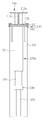
도 1은 본 발명의 실시예에 의한 교번 압입식 기초 보강장치를 설명하기 위한 사시도
도 2는 본 발명의 실시예에 의한 교번 압입식 기초 보강장치에서 수평프레임 및 슬라이딩부재의 결합관계를 설명하기 위한 부분 단면도
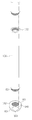
도 3은 본 발명의 실시예에 의한 교번 압입식 기초 보강장치에서 기초파일 및 압입용 슈의 구성 및 결합관계를 설명하기 위한 조립사시도
도 4a 내지 도 4g는 본 발명의 실시예에 의한 교번 압입식 기초 보강공법을 설명하기 위한 일련의 참조도1 is a perspective view for explaining an alternate pressing type basic reinforcing apparatus according to an embodiment of the present invention;
FIG. 2 is a partial cross-sectional view for explaining an engagement relationship between a horizontal frame and a sliding member in an alternate press-fit type basic reinforcing apparatus according to an embodiment of the present invention. FIG.
3 is an assembled perspective view for explaining the constitution and the coupling relationship of the foundation pile and the press-fitting shoe in the alternate press-in type basic reinforcing apparatus according to the embodiment of the present invention.
4A to 4G are a series of reference drawings for explaining an alternate press-fit type basic reinforcement method according to an embodiment of the present invention.
첨부한 도면을 참조하여 본 발명의 실시예들에 의한 교번 압입식 기초 보강장치 및 기초 보강공법에 대하여 상세히 설명한다. 본 발명은 다양한 변경을 가할 수 있고 여러 가지 형태를 가질 수 있는바, 특정 실시예들을 도면에 예시하고 본문에 상세하게 설명하고자 한다. 그러나 이는 본 발명을 특정한 개시 형태에 대해 한정하려는 것이 아니며, 본 발명의 사상 및 기술 범위에 포함되는 모든 변경, 균등물 내지 대체물을 포함하는 것으로 이해되어야 한다. 각 도면을 설명하면서 유사한 참조부호를 유사한 구성요소에 대해 사용하였다. 첨부된 도면에 있어서, 구조물들의 치수는 본 발명의 명확성을 기하기 위하여 실제보다 확대하거나, 개략적인 구성을 이해하기 위하여 실제보다 축소하여 도시한 것이다.The alternate pressing type basic reinforcing apparatus and the basic reinforcing method according to the embodiments of the present invention will be described in detail with reference to the accompanying drawings. The present invention is capable of various modifications and various forms, and specific embodiments are illustrated in the drawings and described in detail in the text. It is to be understood, however, that the invention is not intended to be limited to the particular forms disclosed, but on the contrary, is intended to cover all modifications, equivalents, and alternatives falling within the spirit and scope of the invention. Like reference numerals are used for like elements in describing each drawing. In the accompanying drawings, the dimensions of the structures are enlarged to illustrate the present invention, and are actually shown in a smaller scale than the actual dimensions in order to understand the schematic structure.
또한, 제1 및 제2 등의 용어는 다양한 구성요소들을 설명하는데 사용될 수 있지만, 상기 구성요소들은 상기 용어들에 의해 한정되어서는 안 된다. 상기 용어들은 하나의 구성요소를 다른 구성요소로부터 구별하는 목적으로만 사용된다. 예를 들어, 본 발명의 권리 범위를 벗어나지 않으면서 제1 구성요소는 제2 구성요소로 명명될 수 있고, 유사하게 제2 구성요소도 제1 구성요소로 명명될 수 있다. 한편, 다르게 정의되지 않는 한, 기술적이거나 과학적인 용어를 포함해서 여기서 사용되는 모든 용어들은 본 발명이 속하는 기술분야에서 통상의 지식을 가진 자에 의해 일반적으로 이해되는 것과 동일한 의미를 가지고 있다. 일반적으로 사용되는 사전에 정의되어 있는 것과 같은 용어들은 관련 기술의 문맥 상 가지는 의미와 일치하는 의미를 가지는 것으로 해석되어야 하며, 본 출원에서 명백하게 정의하지 않는 한, 이상적이거나 과도하게 형식적인 의미로 해석되지 않는다.Also, the terms first and second, etc. may be used to describe various components, but the components should not be limited by the terms. The terms are used only for the purpose of distinguishing one component from another. For example, without departing from the scope of the present invention, the first component may be referred to as a second component, and similarly, the second component may also be referred to as a first component. On the other hand, unless otherwise defined, all terms used herein, including technical or scientific terms, have the same meaning as commonly understood by one of ordinary skill in the art to which this invention belongs. Terms such as those defined in commonly used dictionaries are to be interpreted as having a meaning consistent with the contextual meaning of the related art and are to be interpreted as either ideal or overly formal in the sense of the present application Do not.
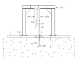
도 1은 본 발명의 실시예에 의한 교번 압입식 기초 보강장치를 설명하기 위한 사시도이고, 도 2는 본 발명의 실시예에 의한 교번 압입식 기초 보강장치에서 수평프레임 및 슬라이딩부재의 결합관계를 설명하기 위한 부분 단면도이며, 도 3은 본 발명의 실시예에 의한 교번 압입식 기초 보강장치에서 기초파일 및 압입용 슈의 구성 및 결합관계를 설명하기 위한 조립사시도이다.FIG. 1 is a perspective view for explaining an alternate press-in type basic reinforcing apparatus according to an embodiment of the present invention, and FIG. 2 is a perspective view showing a combined relationship between a horizontal frame and a sliding member in an alternate pressing type basic reinforcing apparatus according to an embodiment of the present invention Fig. 3 is an assembled perspective view for explaining the structure and coupling relationship of the foundation pile and the press-fitting shoe in the alternate press-fit type basic reinforcing apparatus according to the embodiment of the present invention.
도시된 바와 같이, 본 발명의 교번 압입식 기초 보강장치는, 압입에 따른 반력을 지지하는 지지프레임(110)과, 한 쌍으로 이루어진 제1유압실린더(120a) 및 제2유압실린더(120b)와, 제1유압실린더(120a) 및 제2유압실린더(120b)를 좌우로 슬라이딩 이동시켜주는 슬라이딩부재(130)와, 연장부재(140)와, 압입용 슈(160)를 포함하여 이루어지며, 상기 제1유압실린더(120a) 및 제2유압실린더(120b)를 슬라이딩부재(130)에 의해 좌우로 교번하여 이동시키면서 기초파일(150)을 번갈아 압입할 수 있도록 구성되어 특유의 느린 작동속도를 갖는 유압실린더의 사용에도 불구하고 기초파일에 대한 신속한 압입시공이 가능하게 된다. As shown in the figure, the alternate press-fit basic reinforcing apparatus of the present invention includes a
아래에서는 상기 각 구성요소들을 중심으로 본 발명의 실시예에 의한 교번 압입식 기초 보강장치의 구성에 대해 상세하게 설명하기로 한다. Hereinafter, the configuration of an alternate press-fit type basic reinforcing apparatus according to an embodiment of the present invention will be described in detail with reference to the above-described components.
상기 지지프레임(110)은 상기 기초파일(150)을 압입할 때 발생하는 반력을 지지하는 역할을 하는 것으로, 상호 이격을 두고 수직하게 세워져 지층의 표면에 고정되는 한 쌍의 수직프레임(111)과, 상기 수직프레임(111)의 상단부들을 연결하여 설치된 수평프레임(112)으로 이루어지며 전체적으로 역 U자 형태를 갖는다. The
여기서 상기 수직프레임(111)과 수평프레임(112)은 압입에 따른 반력을 충분히 지지할 수 있도록 높은 강도를 갖는 H형강으로 구비되는 것이 바람직하다. 이 중 수평프레임(112)의 경우 슬라이딩부재(130)에 대하여 레일 역할을 할 수 있도록 H형강을 가로로 눕혀 설치하되 플랜지(1112a,112b)가 웨브(112c)를 중심으로 상측과 하측에 각각 위치하도록 한다. 이로써 상기 슬라이딩부재(130)가 하측 플랜지(112b)를 레일로 삼아 슬라이딩 가능하도록 결합될 수 있다.The
또한, 상기 지지프레임(110)의 수직프레임(111) 하단부는 앵커(111a)(anchor)에 의하여 지층에 견고하게 고정된다. 이를 위해 상기 수직프레임(111)의 하단에는 수직프레임(111)이 차지하는 면적보다 넓은 면적의 플레이트(111a)가 더 구비되고, 플레이트(111a)를 지층의 표면에 고정하는 앵커(111a)(anchor)가 설치된다. 여기서 상기 앵커(111a)의 규격 및 수량은 기초파일(150)의 압입시 예상되는 반력을 고려하여 정하면 되며, 앵커(111a)의 설치는 드릴로 지층을 천공한 후 해머로 앵커(111a)를 박아 넣고 나서 너트로 체결하면 된다. 단, 도ㅇ1과같이 같이 지층 표면에 슬래브(S)가 시공된 경우라면 슬래브(S)를 천공하여 앵커(111a)를 설치하면 되며 슬래브(S) 없이 지층에 바로 설치하는 경우보다 앵커(111a)의 길이는 상대적으로 짧아진다. The lower end of the
이같은 상기 지지프레임(110)의 구성에 따르면 기초파일(150)을 압입할 때 발생하는 반력에 대하여 상기 제1유압실린더(120a) 및 제2유압실린더(120b)를 지지할 수 있는 충분한 지지력을 발휘할 수 있고 앵커(111a)의 너트 체결을 해제할 후 간단히 이동 설치가 가능해진다. According to the structure of the
상기 제1유압실린더(120a) 및 제2유압실린더(120b)는 좌우로 이동하면서 기초파일(150)을 교번하여 압입하도록 구성된다. 이를 위해 제1유압실린더(120a) 및 제2유압실린더(120b)는 몸체(121)와 상기 몸체(121)로부터 진퇴하는(도면상으로 진출시 하강, 후퇴시 상승하는) 아암(122)으로 이루어진 일반적인 형태의 것으로 구비되며 상기 슬라이딩부재(130)에 좌우로 나란히 설치되어 상기 슬라이딩부재(130)가 수평프레임(112)을 따라 좌우로 이동할 때 함께 이동하게 된다. 이같은 구성에 따르면 상기 슬라이딩부재(130)를 이동시키면서 한번은 제1유압실린더(120a)로 기초파일(150)을 압입하고 한번은 제2유압실린더(120b)로 기초파일(150)을 압입하는 방법으로 교번하여 번갈아가면서 기초파일(150)을 압입할 수 있게 된다. 이때 기초파일(150)을 압입하기 위해 각 유압실린더의 아암(122)이 하강한 후에 다시 상승하는 데까지 소요되는 긴 시간을 기다리지 않고 다른 유압실린더를 사용하여 즉시 기초파일(150)에 대한 압입작업을 실시할 수 있는 것이다. 이로써, 유압실린더를 사용하는데 따른 느린 작동속도를 극복하면서 신속한 시공이 가능해진다. The first
상기 슬라이딩부재(130)는 상기 제1유압실린더(120a) 및 제2유압실린더(120b)를 좌우로 교번하여 이동시켜주는 역할을 한다. 이를 위해 상기 슬라이딩부재(130)는 H형강이 가로로 눕혀져 구비된 수평프레임(112)에서 하측 플랜지(112b)에 슬라이딩 가능하도록 결합된다. 이처럼 상기 수평프레임(112)의 하측 플랜지(112b)에 대하여 슬라이딩부재(130)가 결합되는 구성을 도 2에서 확인할 수 있다. 도 2에서 볼 수 있는 것처럼 상기 슬라이딩부재(130)는 하측 플랜지(112b)를 레일로 삼아 그 양편 측변부에 슬라이딩 가능하게 걸쳐지는 ㄱ자형의 슬라이딩 가이드(131)와, 상기 하측 플랜지(112b)의 하측에서 상기 한 쌍의 슬라이딩 가이드(131)를 연결하면서 상기 제1유압실린더(120a)와 제2유압실린더(120b)를 지지해주는 지지패널(132)로 이루어진다. 여기서 상기 슬라이딩부재(130)의 이동시 슬라이딩 가이드(131)와 지지패널(132)이 접촉하는 수평프레임(112)의 하측 플랜지(112b) 영역에는 윤활을 위한 그리스(grease)가 충분한 양으로 도포된다. 이처럼 슬라이딩부재(130)가 구비되면 작업자가 제1유압실린더(120a)나 제2유압실린더(120b)의 몸체(121)를 잡고 수평프레임(112)을 따라 좌우로 간단히 이동시키는 것이 가능해진다. The sliding
상기 연장부재(140)는 상기 제1유압실린더(120a) 및 제2유압실린더(120b)의 아암(122)과 기초파일(150)의 사이에 끼워 넣어 상기 아암(122)의 길이를 연장할 수 있도록 한 부재이다. 상기 연장부재(140)는 강재로 만든 짧은 원통형상으로 연장이 필요한 길이에 따라 여러 개를 적층하여 사용한다. 또한, 도면에 따르면 상기 연장부재(140)의 상하폭이 비교적 짧게 도시되었지만 기초파일(150)을 압입하기 위해 요구되는 길이에 대하여 상기 제1유압실린더(120a) 및 제2유압실린더(120b)의 작용 길이를 고려하여 보다 긴 상하폭을 갖는 것으로 구비될 수 있음은 물론이다. The
상기 압입용 슈(160)(shoe)는 상기 제1유압실린더(120a) 및 제2유압실린더(120b)에 의해 지층에 압입되는 다수의 기초파일(150) 중 최하단에 위치하여 최초 압입되는 기초파일(150)의 하단부에 선택적으로 설치된다. 상기 압입용 슈(160)(shoe)의 구성을 살펴보면 도 3에 도시된 것처럼, 기초파일(150)의 하단부에 형성된 수나사(151)에 나사체결되도록 내경에는 암나사(161)를 갖는 링 형태로 이루어지되, 하단으로 갈수록 외경이 줄어들도록 경사진 외주면(164)을 갖는다. 여기서 상기 압입용 슈(180)는 기초파일(150)의 하단부에 대하여 나사체결뿐만 아니라 끼움방식으로 체결되거나 용접방식으로 접합될 수 있는데 용접방식에 의한 접합이 다른 방식들에 비해 비용 측면에서 유리하기 때문에 가장 바람직하다고 할 수 있다.The
이같이 압입용 슈(160)가 경사진 외주면(164)을 갖게 되면 같은 압력이 가해질 때 지층에 대하여 용이하게 압입될 수 있다. 또한, 상기 압입용 슈(160) 하단의 내경(163)은 상기 기초파일(150)의 내경보다 좁게 형성되는데, 이는 점토층 같은 지층에 압입될 때 기초파일(150) 내부로 유입되는 점토의 양을 제한하여 기초파일(150) 내주면에 대하여 유입되는 지층의 접촉마찰을 줄임으로써 기초파일(150)의 압입이 방해받지 않도록 하기 위함이다. 또한, 상기 압입용 슈(160) 상단부의 외경은 상기 기초파일(150)의 외경보다 넓게 형성되어 상기 기초파일(150)과의 체결시 외측으로 돌출된 단턱부(162)를 형성하도록 하는데, 이는 기초파일(150)이 일단 지층에 압입된 상태가 되면 보다 견고하게 지지력을 발휘할 수 있도록 하기 위함이다. 아울러 점토층 같은 지층에 압입될 때 가장 선단부에서 돌출된 상기 단턱부(162)에 의해 뒤따라 압입되는 기초파일(150)의 외주면에 대하여 지층의 접촉 및 마찰을 줄일 수 있게 되어 기초파일(150)의 압입이 방해받지 않도록 하기 위함이다.Thus, when the press-fitting
참고로, 본 발명의 실시예에 의한 교번 압입식 기초 보강장치에 사용되는 기초파일(150)은 서로를 상하로 연결할 수 있도록 상단부와 하단부에 각각 암나사(152)와 수나사(151) 형성된다. 상기 기초파일(150)은 시공현장의 여건을 고려하여 다양한 규격의 것으로 구비될 수 있는데, 건물 내 좁은 공간에서도 시공이 가능한 최소규격은 상하 길이가 1000mm 내외가 될 수 있다. 예컨대, 이같은 규격의 기초파일(150)을 사용하는 경우 30m 깊이로 지층에 압입한다고 할 때 거의 30개 가까이 사용된다. 시공기간 및 기초파일(150)을 압입하여 시공해야하는 지점의 수를 충분히 고려하여 본 발명의 실시예에 의한 교번 압입식 기초 보강장치를 필요한 최소한의 개수만큼 초기 설치한 후 자리를 이동시키면서 시공한다.
For reference, the
이와 같이 구성된 본 발명의 실시예에 의한 교번 압입식 기초 보강공법을 도 4a 내지 도 4g를 포함하여 첨부한 도면에 의거 상세히 설명하면 다음과 같다. 단, 도 4a 내지 도 4g는 본 발명의 실시예에 의한 교번 압입식 기초 보강공법을 설명하기 위한 일련의 참조도이다. The alternate press-fit type basic reinforcement method according to the embodiment of the present invention will be described in detail with reference to the accompanying drawings, including FIGS. 4A to 4G. 4A to 4G are a series of reference views for explaining an alternate press-fit type basic reinforcement method according to an embodiment of the present invention.
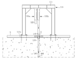
먼저, 도 4a에 도시된 것처럼 지지프레임(110)을 포함한 장치 전체를 기초파일(150)을 압입하기 위한 위치로 이동시킨 후 지층의 표면에 고정한다. 이를 위해 앵커(111a)를 박아 넣고 너트를 체결하는 방법으로 수직프레임(111) 하단에 구비된 플레이트(111a)를 슬래브(S)(슬래브(S)가 시공된 경우) 및 지층의 표면에 견고하게 고정한다. First, as shown in FIG. 4A, the entire apparatus including the
이후, 슬래브(S)를 포함하여 전석층 등 압입이 어려운 특성의 층이 지층의 표면에 존재하는 경우 일정 깊이까지 천공함으로써 기초파일(150)을 압입하기 위한 압입용 자리(H)를 잡는다. 이때 크롤러 드릴(crawler drill)이나 코어드릴(core drill)을 사용하면 된다. 이와 함께, 슬라이딩부재(130)를 수평프레임(112)을 따라 슬라이딩 이동시켜 제1유압실린더(120a)를 상기 압입용 자리(H)의 바로 상측으로 이동시켜준다. Thereafter, when the layer including the slab S is present on the surface of the stratum such that the layer is difficult to be press-fitted, such as an obelisk, it is perforated to a certain depth to hold the indentation H for press-fitting the
이후, 도 4b에 도시된 것처럼 최초 압입될 기초파일(150) 하나를 그 하단부에 압입용 슈(160)를 설치한 상태로 하여 압입용 자리(H)에 초기 삽입하여 지지하고 제1유압실린더(120a)의 아암(122)과 기초파일(150) 사이에 연장부재(140)를 끼워 설치한다. 그러면 상기 제1유압실린더(120a)와 기초파일(150) 사이의 간극이 사라지고 기초파일(150)을 압입할 수 있는 상태가 된다. Thereafter, as shown in FIG. 4B, one of the
이후, 도 4c와 같이 제1유압실린더(120a)를 작동하여 아암(122)을 하강시켜주면 자리를 잡고 있던 기초파일(150)이 지층에 압입되기 시작한다. 이때 상기 제1유압실린더(120a)의 아암(122)을 통해 가하는 초기 압력은 지층에 대한 기초 조사자료를 토대로 예측하여 설정한 것인데, 만일 초기 압력에 의해 지층에 대한 기초파일(150)의 압입이 이루어지지 않는 경우에는 기초파일(150)의 압입이 이루어질 때까지 가하는 압력을 단계적으로 높여주고 실제 기초파일(150)의 압입이 이루어지는 압력을 압입용 압력으로 재설정하여 제2유압실린더(120b)에도 적용한다. Thereafter, as shown in FIG. 4C, the first
이후, 제1유압실린더(120a)에 의해 기초파일(150)의 압입이 완료되면 도 4d와 같이 상기 제1유압실린더(120a)의 아암(122)이 상승하는 시간동안 기다리지 않고 상기 제1유압실린더(120a)를 대신하여 아암(122)이 상승된 상태로 있는 제2유압실린더(120b)를 압입용 자리(H) 상부로 위치시키기 위해 슬라이딩부재(130)를 이동시켜준다. 4D, when the
이후, 도 4e와 같이 새로운 기초파일(150)을 앞서 제1유압실린더(120a)에 의해 지층에 압입된 기초파일(150) 상단에 나사체결하여 연결하고 도 4f와 같이 제2유압실린더(120b)의 아암(122)과 새로운 기초파일(150) 사이에 연장부재(140)를 끼워 넣는다. 4E, the new
이후, 지체 없이 제2유압실린더(120b)를 작동하여 아암(122)을 하강함으로써 도 4g와 같이 새로운 기초파일(150)을 지층에 압입한다. 이때 상기 제2유압실린더(120b)가 가하는 압력은 위에서 재설정된 압입용 압력에 따른다. 이로써 두 개의 기초파일(150)에 대한 압입작업이 완료된다. Thereafter, the second
전술된 바와 같이 제2유압실린더(120b)에 의한 새로운 기초파일(150)의 압입이 완료되면, 앞서와 마찬가지로 제2유압실린더(120b)의 아암(122)이 상승하는 시간동안 기다리지 않고 상기 제2유압실린더(120b)를 대신하여 아암(122)이 상승된 상태인 제1유압실린더(120a)를 위치시키고 또 다른 새로운 기초파일(150)을 앞서 제2유압실린더(120b)에 의해 지층에 압입된 기초파일(150) 상단에 연결하여 상기 제1유압실린더(120a)에 의해 지체 없이 압입하는 방식으로 제1유압실린더(120a)와 제2유압실린더(120b)를 교번하면서 정해진 개수만큼 기초파일(150)을 번갈아 압입해주면 된다. When the press of the
이상에서 본 발명의 바람직한 실시예를 설명하였으나, 본 발명은 다양한 변화와 변경 및 균등물을 사용할 수 있다. 본 발명은 상기 실시예를 적절히 변형하여 동일하게 응용할 수 있음이 명확하다. 따라서 상기 기재 내용은 하기 특허청구범위의 한계에 의해 정해지는 본 발명의 범위를 한정하는 것이 아니다.
While the present invention has been particularly shown and described with reference to exemplary embodiments thereof, it is to be understood that the invention is not limited to the disclosed exemplary embodiments. It is clear that the present invention can be suitably modified and applied in the same manner. Therefore, the above description does not limit the scope of the present invention, which is defined by the limitations of the following claims.
110 : 지지프레임 111 : 수직프레임
111a : 플레이트 111b : 앵커
112 : 수평프레임 120a, 120b : 제1유압실린더, 제2유압실린더
121 : 몸체 122 : 아암
130 : 슬라이딩부재 131 : 슬라이딩 가이드
132 : 지지패널 140 : 연장부재
150 : 기초파일 160 : 압입용 슈 110: support frame 111: vertical frame
111a:
112:
121: body 122: arm
130: Sliding member 131: Sliding guide
132: support panel 140: extension member
150: Foundation file 160: Indentation shoe
Claims (11)
상기 수평프레임을 따라 좌우로 슬라이딩 가능하게 설치된 슬라이딩부재와;
좌우로 이동 가능하도록 상기 슬라이딩부재에 좌우로 나란히 설치되어, 상기 슬라이딩부재에 의해 교번하여 좌우로 이동하면서 기초파일을 연속적으로 지층에 압입할 수 있도록 한 제1유압실린더 및 제2유압실린더;를 포함하여 구성되는 교번 압입식 기초 보강장치.A supporting frame formed of a pair of vertical frames vertically erected with mutual spacing and fixed to the surface of the ground layer and a horizontal frame connected with upper ends of the vertical frame;
A sliding member slidably installed laterally along the horizontal frame;
And a first hydraulic cylinder and a second hydraulic cylinder which are arranged side by side on the sliding member so as to be movable left and right, and which can press the base file continuously into the layer while alternately moving left and right by the sliding member Wherein the first reinforcing member and the second reinforcing reinforcing reinforcing member are made of a metal.
상기 수평프레임은 H형강을 가로로 눕힌 것으로 구비하되 상기 H형강의 플랜지가 상측과 하측에 각각 위치하도록 하며,
상기 슬라이딩부재는 상기 H형강의 하측 플랜지를 레일로 삼아 그 양편 측변부에 슬라이딩 가능하게 걸쳐지는 ㄱ자형의 슬라이딩 가이드와, 상기 하측 플랜지의 하측에서 상기 한 쌍의 슬라이딩 가이드 간을 연결하면서 상기 제1유압실린더 및 제2유압실린더를 지지해주는 지지패널로 이루어지는 것을 특징으로 하는 교번 압입식 기초 보강장치.The method according to claim 1,
Wherein the horizontal frame has an H-shaped cross-section lying transversely, and a flange of the H-shaped section is positioned on the upper side and the lower side, respectively,
Wherein the sliding member includes a pair of sliding guides that are slidably disposed on both sides of the lower flange of the H-shaped portion as a rail and a pair of sliding guides which are connected to each other at a lower side of the lower flange, And a support panel for supporting the hydraulic cylinder and the second hydraulic cylinder.
상기 수직프레임의 하단에는 플레이트가 구비되고, 상기 플레이트를 지층의 표면에 고정하는 앵커(anchor)가 설치되는 것을 특징으로 하는 교번 압입식 기초 보강장치.3. The method of claim 2,
And an anchor for fixing the plate to the surface of the ground layer is provided at a lower end of the vertical frame.
상기 기초파일은 서로를 상하로 연결할 수 있도록 상단부와 하단부에 각각 암나사와 수나사 형성된 것을 특징으로 하는 교번 압입식 기초 보강장치.The method according to claim 1,
Wherein the foundation piles are formed with a female screw and a male screw at an upper end and a lower end, respectively, so that the foundation piles can be connected to each other up and down.
상기 제1유압실린더 및 제2유압실린더에 의해 지층에 압입되는 다수의 기초파일 중 최하단에 위치하여 지층에 최초 압입되는 기초파일의 하단부에 설치할 수 있도록 압입용 슈(shoe)가 구비되며,
상기 압입용 슈는, 상기 기초파일의 하단부에 결합될 수 있도록 링 형태로 이루어지되, 하단으로 갈수록 외경이 줄어들도록 경사진 외주면으로 이루어지고, 하단의 내경은 상기 기초파일의 내경보다 좁게 형성되며, 상단부의 외경은 상기 기초파일의 외경보다 넓게 형성되어 상기 기초파일과의 체결시 외측으로 돌출된 단턱부를 형성하는 것을 특징으로 하는 교번 압입식 기초 보강장치.5. The method of claim 4,
A shoe for press-fitting is provided at the lower end of a plurality of foundation papers press-fitted into the ground layer by the first hydraulic cylinder and the second hydraulic cylinder so as to be installed at the lower end of the foundation pile to be first press-
Wherein the press-fit shoe is formed in a ring shape so as to be engageable with a lower end portion of the foundation pile, and has an inclined outer circumferential surface that decreases in outer diameter toward the lower end, and an inner diameter of the lower end is narrower than an inner diameter of the foundation pile, Wherein an outer diameter of the upper end portion is formed wider than an outer diameter of the foundation pile to form a step portion projecting outwardly when fastened to the foundation pile.
상기 제1유압실린더 및 제2유압실린더의 아암과 기초파일의 사이에 위치시켜 상기 아암의 길이를 연장할 수 있도록 한 연장부재를 더 구비하는 것을 특징으로 하는 교번 압입식 기초 보강장치.5. The method of claim 4,
Further comprising an extension member positioned between the arms of the first hydraulic cylinder and the second hydraulic cylinder and the base pile to extend the length of the arm.
좌우로 나란히 설치된 제1유압실린더 및 제2유압실린더를 구비하고,
제1유압실린더에 의해 기초파일을 지층에 압입한 후, 상기 제1유압실린더의 아암이 상승하는 시간동안 기다리지 않고 상기 제1유압실린더를 대신하여 아암이 상승된 상태인 제2유압실린더를 위치시키고 새로운 기초파일을 앞서 제1유압실린더에 의해 지층에 압입된 기초파일 상단에 연결하여 상기 제2유압실린더에 의해 지체 없이 압입하며,
상기 제2유압실린더에 의해 기초파일을 지층에 압입한 후, 상기 제2유압실린더의 아암이 상승하는 시간동안 기다리지 않고 상기 제2유압실린더를 대신하여 아암이 상승된 상태인 제1유압실린더를 위치시키고 또 다른 새로운 기초파일을 앞서 제2유압실린더에 의해 지층에 압입되어 있는 기초파일 상단에 연결하여 상기 제1유압실린더에 의해 지체 없이 압입하는 방식으로 제1유압실린더와 제2유압실린더를 교번하면서 기초파일을 연속적으로 압입하는 것을 특징으로 하는 교번 압입식 기초 보강공법.A foundation reinforcing method for reinforcing a foundation by press-fitting a foundation file continuously in multiple stages,
A first hydraulic cylinder and a second hydraulic cylinder provided side by side,
After the base pile is pressed into the ground layer by the first hydraulic cylinder, the second hydraulic cylinder in which the arm is in the raised state is positioned instead of the first hydraulic cylinder without waiting for the time for the arm of the first hydraulic cylinder to rise A new foundation file is connected to the upper end of the foundation file press-fitted in the ground layer by the first hydraulic cylinder and is press-fitted by the second hydraulic cylinder without delay,
A first hydraulic cylinder in which the arm is in an elevated state in place of the second hydraulic cylinder is positioned at a position corresponding to the position of the second hydraulic cylinder, And another new basic file is connected to the upper end of the base file pressed in advance by the second hydraulic cylinder, and the first hydraulic cylinder and the second hydraulic cylinder are alternately replaced in such a manner that they are pressed in by the first hydraulic cylinder without delay Characterized in that the foundation file is continuously press-fitted.
상기 기초파일은 상단부와 하단부에 각각 암나사와 수나사 형성되어 기초파일 서로 간에 나사체결되도록 한 것을 특징으로 하는 교번 압입식 기초 보강공법.8. The method of claim 7,
Wherein the foundation file is formed by a female screw and a male screw at the upper end and the lower end, respectively, so that the foundation files are screwed together with each other.
상기 제1유압실린더 및 제2유압실린더에 의해 지층에 압입되는 다수의 기초파일 중 최하단에 위치하여 지층에 최초 압입되는 기초파일의 하단부에 압입용 슈(shoe)를 설치하며,
상기 압입용 슈는, 상기 기초파일의 하단부에 결합될 수 있도록 링 형태로 이루어지되, 하단으로 갈수록 외경이 줄어들도록 경사진 외주면으로 이루어지고, 하단의 내경은 상기 기초파일의 내경보다 좁게 형성되며, 상단부의 외경은 상기 기초파일의 외경보다 넓게 형성되어 상기 기초파일과의 체결시 외측으로 돌출된 단턱부를 형성하는 것을 특징으로 하는 교번 압입식 기초 보강공법.9. The method of claim 8,
A shoe for press-fitting is provided at the lower end of a foundation pile which is located at the lowermost end of the plurality of foundation piles press-fitted into the ground layer by the first hydraulic cylinder and the second hydraulic cylinder,
Wherein the press-fit shoe is formed in a ring shape so as to be engageable with a lower end portion of the foundation pile, and has an inclined outer circumferential surface that decreases in outer diameter toward the lower end, and an inner diameter of the lower end is narrower than an inner diameter of the foundation pile, Wherein the outer diameter of the upper end portion is formed wider than the outer diameter of the foundation pile to form a step portion protruding outwardly when fastened to the foundation pile.
다수의 기초파일 중 최초의 기초파일을 압입하기 전에 지층의 표면을 일정 깊이까지 드릴로 천공하여 압입용 자리를 잡는 것을 특징으로 하는 교번 압입식 기초 보강공법.The method according to claim 1,
Wherein the surface of the stratum is drilled to a certain depth by drilling before the first foundation file of the plurality of foundation files is press-fitted, thereby holding the indentation for reinforcement.
다수의 기초파일 중 최초의 기초파일을 압입할 때에는 지층에 대하여 기초파일의 압입이 이루어질 때까지 제1유압실린더에 의해 가하는 압력을 단계적으로 높여주고, 기초파일의 압입이 이루어지는 압력을 압입용 압력으로 재설정하여 제2유압실린더에 적용하는 것을 특징으로 하는 교번 압입식 기초 보강공법.11. The method of claim 10,
The pressure applied by the first hydraulic cylinder is increased step by step until the foundation file is press-fitted into the foundation layer, and the pressure at which the foundation file is press-fitted is set to the press-fitting pressure And is applied to the second hydraulic cylinder.
Priority Applications (1)
| Application Number | Priority Date | Filing Date | Title |
|---|---|---|---|
| KR1020130064621A KR101514763B1 (en) | 2013-06-05 | 2013-06-05 | Alternation pressure type foundation strengthening apparatus and method |
Applications Claiming Priority (1)
| Application Number | Priority Date | Filing Date | Title |
|---|---|---|---|
| KR1020130064621A KR101514763B1 (en) | 2013-06-05 | 2013-06-05 | Alternation pressure type foundation strengthening apparatus and method |
Publications (2)
| Publication Number | Publication Date |
|---|---|
| KR20140142902A true KR20140142902A (en) | 2014-12-15 |
| KR101514763B1 KR101514763B1 (en) | 2015-04-23 |
Family
ID=52460205
Family Applications (1)
| Application Number | Title | Priority Date | Filing Date |
|---|---|---|---|
| KR1020130064621A KR101514763B1 (en) | 2013-06-05 | 2013-06-05 | Alternation pressure type foundation strengthening apparatus and method |
Country Status (1)
| Country | Link |
|---|---|
| KR (1) | KR101514763B1 (en) |
Cited By (4)
| Publication number | Priority date | Publication date | Assignee | Title |
|---|---|---|---|---|
| CN104929122A (en) * | 2015-05-20 | 2015-09-23 | 成都科创佳思科技有限公司 | Continuous static pile driver |
| CN105649082A (en) * | 2016-02-29 | 2016-06-08 | 成都绿迪科技有限公司 | Static pile driver capable of being adjusted and located |
| JP2017190635A (en) * | 2016-04-14 | 2017-10-19 | 清水建設株式会社 | Construction method for steel pipe pile |
| CN109958126A (en) * | 2017-12-22 | 2019-07-02 | 徐州盾安重工机械制造有限公司 | The pile foundation construction method of narrow space |
Family Cites Families (2)
| Publication number | Priority date | Publication date | Assignee | Title |
|---|---|---|---|---|
| JP3921299B2 (en) * | 1998-06-12 | 2007-05-30 | 株式会社技研製作所 | Pile press-fitting device |
| JP5390553B2 (en) * | 2011-03-23 | 2014-01-15 | 株式会社あけぼの産業 | Pile press-fitting device |
-
2013
- 2013-06-05 KR KR1020130064621A patent/KR101514763B1/en active IP Right Grant
Cited By (4)
| Publication number | Priority date | Publication date | Assignee | Title |
|---|---|---|---|---|
| CN104929122A (en) * | 2015-05-20 | 2015-09-23 | 成都科创佳思科技有限公司 | Continuous static pile driver |
| CN105649082A (en) * | 2016-02-29 | 2016-06-08 | 成都绿迪科技有限公司 | Static pile driver capable of being adjusted and located |
| JP2017190635A (en) * | 2016-04-14 | 2017-10-19 | 清水建設株式会社 | Construction method for steel pipe pile |
| CN109958126A (en) * | 2017-12-22 | 2019-07-02 | 徐州盾安重工机械制造有限公司 | The pile foundation construction method of narrow space |
Also Published As
| Publication number | Publication date |
|---|---|
| KR101514763B1 (en) | 2015-04-23 |
Similar Documents
| Publication | Publication Date | Title |
|---|---|---|
| KR100654228B1 (en) | Structure lifting method possible to be re-lifting using pile member | |
| KR100767093B1 (en) | Structure lifting method using pile adjustable the length | |
| KR101514763B1 (en) | Alternation pressure type foundation strengthening apparatus and method | |
| JP6461576B2 (en) | Building raising structure | |
| KR101103530B1 (en) | Apparatus for restoration of disparity sinking construction or introducing pre-stress of pipe pile | |
| KR20210033815A (en) | Method for strengthening the foundation of a structure with improved construction precision and reinforced structural strength | |
| KR101377019B1 (en) | Reactive forcing device using guide rail and foundation reinforcing method therewith | |
| KR101427340B1 (en) | Apparatus and method for pressing steel pipe | |
| JP5895320B2 (en) | Method for constructing steel structure and fixing member for steel structure | |
| KR20140065321A (en) | Apparatus for pressing of pile and operation method of the same | |
| AU2004263551A1 (en) | Pile anchor head for an underpinning pile and method of preloading the same | |
| KR101813518B1 (en) | Pre-loading method for fundamental pile | |
| CN201459776U (en) | Rock slope prestress anchorage cable detection tensioning device | |
| KR20110029877A (en) | Structure consecutive lifting apparatus and lifting method using that | |
| KR101426066B1 (en) | End supporting multi micro pile and method for reinforcing structure base using this | |
| JP6082614B2 (en) | Reconstruction method of existing building and pedestal for ground anchor | |
| JP2010084503A (en) | Structure and method for joining concrete column and steel-frame beam | |
| JP3048994B2 (en) | Rebar pull-out tester | |
| KR101785011B1 (en) | Pre-loading apparatus for pile and pre-loading method using the same | |
| JP5647448B2 (en) | Column repair method for multi-story building | |
| KR101574663B1 (en) | Apparatus and method for penetrating pile | |
| KR101689781B1 (en) | Pile pressing apparatus using foundation fixing member and horizontal reinforcing member for pile pressing and the construction method therefor | |
| JP3810759B2 (en) | Edge widening structure of existing substructure by precast block and its construction method | |
| KR101528846B1 (en) | Reactive forcing device using jack lifting apparatus and foundation reinforcing method therewith | |
| KR101445369B1 (en) | Soil Nailing Device Using Connector and Construction Method Using the Same |
Legal Events
| Date | Code | Title | Description |
|---|---|---|---|
| A201 | Request for examination | ||
| E902 | Notification of reason for refusal | ||
| GRNT | Written decision to grant | ||
| FPAY | Annual fee payment |
Payment date: 20190417 Year of fee payment: 5 |
|
| R401 | Registration of restoration |