KR20140116931A - Bleedout detection system - Google Patents
Bleedout detection system Download PDFInfo
- Publication number
- KR20140116931A KR20140116931A KR1020147022736A KR20147022736A KR20140116931A KR 20140116931 A KR20140116931 A KR 20140116931A KR 1020147022736 A KR1020147022736 A KR 1020147022736A KR 20147022736 A KR20147022736 A KR 20147022736A KR 20140116931 A KR20140116931 A KR 20140116931A
- Authority
- KR
- South Korea
- Prior art keywords
- bleed
- mold
- programmable controller
- continuous
- detection system
- Prior art date
Links
Images


Classifications
-
- B—PERFORMING OPERATIONS; TRANSPORTING
- B22—CASTING; POWDER METALLURGY
- B22D—CASTING OF METALS; CASTING OF OTHER SUBSTANCES BY THE SAME PROCESSES OR DEVICES
- B22D11/00—Continuous casting of metals, i.e. casting in indefinite lengths
- B22D11/14—Plants for continuous casting
- B22D11/148—Safety arrangements
-
- B—PERFORMING OPERATIONS; TRANSPORTING
- B22—CASTING; POWDER METALLURGY
- B22D—CASTING OF METALS; CASTING OF OTHER SUBSTANCES BY THE SAME PROCESSES OR DEVICES
- B22D11/00—Continuous casting of metals, i.e. casting in indefinite lengths
- B22D11/16—Controlling or regulating processes or operations
-
- B—PERFORMING OPERATIONS; TRANSPORTING
- B22—CASTING; POWDER METALLURGY
- B22D—CASTING OF METALS; CASTING OF OTHER SUBSTANCES BY THE SAME PROCESSES OR DEVICES
- B22D46/00—Controlling, supervising, not restricted to casting covered by a single main group, e.g. for safety reasons
Landscapes
- Engineering & Computer Science (AREA)
- Mechanical Engineering (AREA)
- Continuous Casting (AREA)
- Investigating Or Analyzing Materials By The Use Of Electric Means (AREA)
- Examining Or Testing Airtightness (AREA)
- Waste-Gas Treatment And Other Accessory Devices For Furnaces (AREA)
- Measurement Of Current Or Voltage (AREA)
- Measurement Of Levels Of Liquids Or Fluent Solid Materials (AREA)
Abstract
블리드아웃 검출 시스템을 갖는 연속적 캐스팅 금형이 기재되며, 상기 금형은, 캐스팅 금형 프레임워크, 금형 유입구 및 금형 배출구(상기 금형 배출구는 금형 캐비티 주변부를 갖는다)를 갖는 용융 금속 캐스팅 금형; 및 블리드아웃 검출 시스템(상기 블리드아웃 검출 시스템은, 상기 금형 배출구 주변부의 또는 상기 금형 배출구 주변부 부근의 센서/컨덕터에 평형 전류를 제공하는 신호 발생기; 상기 센서/컨덕터에 전기적으로 접속된 전류 검출기를 포함할 수 있다); 및 상기 센서/컨덕터의 상태에 관하여 상기 블리드아웃 검출 시스템으로부터 전기 신호를 수신하도록 구성된 프로그램화 가능 제어기를 포함할 수 있다.A continuous casting mold is described having a bleed-out detection system, the mold including a casting mold framework, a mold inlet and a mold outlet (the mold outlet having a mold cavity periphery); And a bleed-out detection system, wherein the bleed-out detection system includes a signal generator providing a balanced current to a sensor / conductor in the vicinity of the mold outlet or in the vicinity of the mold outlet, and a current detector electrically connected to the sensor / can do); And a programmable controller configured to receive an electrical signal from the bleed-out detection system as to the status of the sensor / conductor.

Description
관련 출원에 대한 상호 참조Cross-reference to related application
본 출원은 임의의 기타 출원에 대해 우선권을 주장하지 않는다.
This application does not claim priority as to any other application.
기술분야Technical field
본 발명은, 반연속적 또는 연속적 캐스팅 용융 금속 금형(casting molten metal mold)을 사용하여 캐스팅되는 응고된 금속 덩어리로부터의 원치않는 용융 금속 누출의 제어 시스템에 대한 검출 및 알림(notification)에 있어서 입력값 및/또는 출력값을 갖는 센서의 사용과 관련된다. 본 발명은 개선된 블리드아웃 검출 시스템(bleedout detection system)에 관한 것이다.
The present invention relates to the detection and notification of a control system of unwanted molten metal leaks from solidified metal agglomerates cast using a semi-continuous or continuous casting molten metal mold, / Or < / RTI > The present invention relates to an improved bleedout detection system.
금속 잉곳(ingot)들, 빌렛(billet)들 및 기타 캐스트파트(castpart)들은 통상적으로는 금속 캐스팅 설비의 바닥 수준(floor level) 아래의 대형 캐스팅 피트(pit) 위에 배치된 수직으로 배향된 금형들을 사용하는 캐스팅 공정에 의해 형성되지만, 본 발명은 수평 금형에서도 사용될 수 있다. 상기 수직 캐스팅 금형의 더 저부의 컴포넌트(component)가 출발 블록이다. 상기 캐스팅 공정이 시작될 때, 상기 출발 블록들은 이들의 가장 상부(upward-most)의 위치에 그리고 금형들 내에 있게 된다. 용융 금속이 상기 금형의 구멍 또는 캐비티 내로 부어지고 (통상적으로는 물에 의해) 냉각되는 동안에, 상기 출발 블록은 유압 실린더 또는 기타 장치에 의해 소정의 속도로 서서히 하강한다. 상기 출발 블록이 하강함에 따라, 응고된 금속 또는 알루미늄이 상기 금형의 기저부로부터 배출되어 각종 기하학적 구조의 잉곳들, 원형체(round)들 또는 빌렛들이 형성되며, 이들은 본 명세서에서 캐스트파트들이라고도 지칭될 수 있다.Metallic ingots, billets and other cast parts typically have vertically oriented dies disposed on a large casting pit below the floor level of the metal casting facility Although formed by the casting process used, the present invention can also be used in horizontal molds. The component at the bottom of the vertical casting mold is the start block. When the casting process is started, the starting blocks are in their upward-most positions and in the molds. While the molten metal is poured into the mold cavity or cavity (typically by water) and the molten metal is cooled, the departing block is slowly lowered by the hydraulic cylinder or other device at a predetermined rate. As the starting block descends, the solidified metal or aluminum is discharged from the base of the mold to form ingots, rounds or billets of various geometries, which may also be referred to herein as cast parts have.
본 발명은 일반적으로는 알루미늄, 황동, 납, 아연, 마그네슘, 구리, 강철 등을 비제한적으로 포함하는 금속들의 캐스팅에 관한 것이지만, 주어진 실시예 및 기재된 바람직한 양태는 알루미늄에 관한 것일 수 있고, 따라서, 본 발명은 더욱 일반적으로는 금속들에 적용되긴 하지만, 알루미늄 또는 용융 금속이란 용어가 본 명세서 전반에 걸쳐 일관되게 사용될 수 있다.Although the present invention is generally directed to casting metals that include, but are not limited to aluminum, brass, lead, zinc, magnesium, copper, steel, etc., the given embodiments and the described preferred embodiments may be of aluminum, Although the present invention is more generally applied to metals, the term aluminum or molten metal can be used consistently throughout this specification.
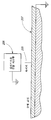
수직 캐스팅 배열을 달성하고 구성하는 다수의 방식들이 존재하지만, 도 1은 빌렛 테이블 캐스팅(billet table casting) 배열의 일례를 예시한다. 도 1에서, 알루미늄의 수직 캐스팅은 일반적으로는 공장 바닥 높이 수준 아래의 캐스팅 피트 내에서 수행된다. 상기 캐스팅 피트 바닥(101a)의 바로 아래에는 케이슨(caisson)(103)이 존재하며, 상기 케이슨 내에 유압 실린더를 위한 유압 실린더 배럴(102)이 위치한다.Although there are many ways of achieving and configuring a vertical casting arrangement, Figure 1 illustrates an example of a billet table casting arrangement. In Fig. 1, the vertical casting of aluminum is generally carried out in a casting pit below the factory floor height level. Just under the casting pit floor 101a is a
도 1에 도시된 바와 같이, 캐스팅 피트(101) 및 케이슨(103) 내에 도시된, 통상적인 수직 알루미늄 캐스팅 장치의 더 저부의 컴포넌트들은, 유압 실린더 배럴(102), 램(ram)(106), 실장 베이스 하우징(mounting base housing)(105), 플래턴(platen)(107) 및 (출발 헤드 또는 바텀 블록 베이스라고도 지칭되는) 출발 블록 베이스(108)이며, 이들은 모두 상기 캐스팅 설비 바닥(104) 아래의 높이에 도시되어 있다.1, the components of the lower portion of a typical vertical aluminum casting apparatus, shown within the
상기 실장 베이스 하우징(105)은 상기 캐스팅 피트(101)의 바닥(101a)에 실장되어 있으며, 상기 바닥의 아래에는 상기 케이슨(103)이 존재한다. 상기 케이슨(103)은 이의 측벽(103b)들과 이의 바닥(103a)에 의해 한정된다.The
또한 통상적인 금형 테이블 어셈블리(110)가 도 1에 도시되어 있으며, 이는 유압 실린더(111)에 의해 도시된 바와 같이 젖혀질 수 있는데, 상기 유압 실린더는 도 1에 도시된 바와 같이, 금형 테이블 틸트 암(tilt arm)(110a)을 밀어서 이것이 점(point)(112) 주위로 선회하도록 하고 이에 의해 상기 주요 캐스팅 프레임 어셈블리가 들어올려져 회전하도록 한다. 또한 상기 금형 테이블 어셈블리들이 상기 캐스팅 피트 위의 캐스팅 위치로 그리고 상기 위치로부터 이동하도록 하는 금형 테이블 캐리지들도 존재한다.A conventional
도 1은 또한, 상기 플래턴(107) 및 상기 출발 블록 베이스(108)가 상기 캐스팅 피트(101) 내로 부분적으로 하강하며 캐스트파트 또는 빌렛(113)이 부분적으로 형성되는 것을 도시한다. 캐스트파트(113)는 상기 출발 블록 베이스(108) 상에 있으며, 이들 모두는 당해 기술분야에 공지되어 있고, 따라서 더 상세히 도시하거나 설명할 필요가 없다. 출발 블록이란 용어가, 부품(item)(114)에 사용되었으나, 바텀 블록 및 출발 헤드라는 용어들도 당해 산업에서 부품(114)을 나타내는 데 사용되며, 잉곳이 캐스팅되는 경우에는 바텀 블록이, 그리고 빌렛이 캐스팅되는 경우에는 출발 헤드가 통상적으로 사용된다는 것을 주지해야 한다.Figure 1 also shows that the
도 1에서 상기 출발 블록 베이스(108)는 단지 하나의 출발 블록(114) 및 페디스털(pedestal)(115)을 나타내지만, 후속 도면들에 도시된 바와 같이 그리고 공지되어 있는 바와 같이, 통상적으로는 각각의 출발 블록 베이스 상에 각각 실장된 다수개가 존재하며, 이들은, 캐스팅 공정 동안에 상기 출발 블록이 하강함에 따라, 빌렛들, 특정 조형물(shape)들 또는 잉곳들을 동시에 캐스팅한다.1, the
유압 유체가 충분한 압력에서 상기 유압 실린더에 도입될 때, 상기 램(106), 그리고 결과적으로 상기 출발 블록(114)은 상기 캐스팅 공정을 위한 목적하는 출발 높이 수준으로 상승되며, 이때 상기 출발 블록들은 상기 금형 테이블 어셈블리(110) 내에 있게 된다.When the hydraulic fluid is introduced into the hydraulic cylinder at sufficient pressure, the ram 106, and consequently the
상기 출발 블록 베이스(108)의 하강은, 상기 실린더로부터 상기 유압 유체를 소정의 속도로 미터링(metering)하여 상기 램(106) 그리고 결과적으로 상기 출발 블록을 소정의 제어된 속도로 하강시킴으로써 달성된다. 상기 공정 동안에 통상적으로는 물 냉각 수단들을 사용하여 상기 금형을 제어가능하게 냉각시켜, 배출되는 잉곳들 또는 빌렛들의 응고를 돕는다.The descent of the
금형 테이블들에 적합한 다수의 금형 및 캐스팅 기술들이 존재하며, 이들은 당해 기술분야의 통상의 숙련가들에 의해 공지되어 있기 때문에, 특별히 본 발명의 각종 양태들을 실시하도록 요구되지는 않는다.There are a number of mold and casting techniques suitable for mold tables, and are not required to specifically embody various aspects of the present invention, as they are well known to those of ordinary skill in the art.
금형 테이블들이 위치되는 다수의 그리고 상이한 크기 및 구성의 캐스팅 피트들이 존재하기 때문에, 금형 테이블들은 모든 크기들 및 구성들로 생산된다. 따라서, 특정 분야에 적합한 금형 테이블에 대한 요구들 및 요건들은 다수의 인자들에 의존하며, 이들 중 몇몇은 캐스팅 피트의 치수, 물 공급원의 위치(들) 및 상기 피트를 작동시키는 개체의 실행을 포함한다.Because there are a number of cast pits of different sizes and configurations in which the mold tables are located, the mold tables are produced in all sizes and configurations. Thus, the requirements and requirements for a mold table suitable for a particular field depend on a number of factors, some of which include the dimensions of the casting pit, the location (s) of the water source and the execution of the object that actuates the pit do.
통상적인 금형 테이블의 상부 측은 금속 분배 시스템에 작동적으로 접속되거나 상호 작용한다. 또한 통상적인 금형 테이블은 자신이 수용하고 있는 금형들에 작동적으로 접속된다.The upper side of a conventional mold table is operatively connected to or interacts with the metal distribution system. A typical mold table is also operatively connected to the molds it houses.
금속이 반연속적 또는 연속적 캐스트 수직 금형을 사용하여 캐스팅되는 경우, 용융 금속은 상기 금형 내에서 냉각되고, 상기 출발 블록 베이스가 하강함에 따라 상기 금형의 저부 말단으로부터 연속적으로 배출된다. 상기 배출되는 빌렛(113), 잉곳 또는 기타 구성물은 이의 목적하는 형상을 유지하기 위해 충분히 응고되도록 의도된다. 상기 배출되는 응고된 금속과 투과성 링 벽 사이에 에어 갭이 존재한다. 이의 아래에, 상기 배출되는 응고된 금속과 상기 금형의 더 낮은 부분 및 관련 장치 사이에도 금형 에어 캐비티가 존재한다.When the metal is cast using a semicontinuous or continuous cast vertical mold, molten metal is cooled in the mold and continuously discharged from the bottom end of the mold as the starting block base descends. The discharged
상기 캐스팅 공정은 일반적으로는 윤활제를 포함하는 유체를 사용하기 때문에, 상기 유체를 금형 캐비티 주위의 목적하는 위치들에 전달하도록 설계된 도관 및/또는 배관이 필연적으로 존재한다. 상기 윤활제라는 용어는 본 명세서 전반에 걸쳐 사용될 것이지만, 이는 또한, 윤활제든 아니든, 모든 타입의 유체들을 의미하며, 이형제들도 포함할 수 있는 것으로 이해된다.Because the casting process generally uses a fluid containing a lubricant, there are inevitably conduits and / or piping designed to transfer the fluid to desired locations around the mold cavity. The term lubricant will be used throughout this specification, but it also means any type of fluid, whether lubricant or not, and is understood to include mold release agents.
캐스팅 피트 및 용융 금속 안과 주변에서의 작업은 잠재적으로 위험할 수 있으며, 안전성을 증가시키기 위한, 그리고 상기 장치의 작동자들이 노출되는 위험 또는 사고 가능성을 최소화시키기 위한 방법을 계속해서 찾는 것이 요망된다. 또한, 상기 장치 및 주변 설비들에 대한 잠재적인 손상 가능성 및 이와 관련된 비용을 감소시키는 것이 유리하다.
Casting pits and molten metal work around the perimeter can be potentially dangerous and it is desirable to continue searching for ways to increase safety and minimize the risk of exposure or accident to the operators of the apparatus. It is also advantageous to reduce the potential damage potential and associated costs for the device and peripheral equipment.
이하, 본 발명의 바람직한 양태들을 다음의 첨부 도면들을 참조로 하여 설명한다.
도 1은 통상적인 수직 캐스팅 피트, 케이슨 및 금속 캐스팅 장치의 정면도이다.
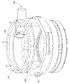
도 2는 본 발명의 양태들에 사용될 수 있는 다수의 금형 프레임워크(framework)들 중의 하나의 투시도이다.
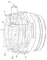
도 2a는 본 발명의 양태들에 사용될 수 있는 다수의 금형 프레임워크들 중의 하나의 투시도이며, 캐스트 제품으로부터의 용융 금속의 블리드아웃이 도시되어 있다.
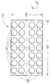
도 3은 4개의 가로열(row)들 및 7개의 세로열(column)들의 용융 금속 금형들을 갖는 금형 테이블의 개략적 평면도이다.
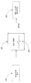
도 4는 프로그램화 가능 제어기에 접속된 블리드아웃 검출 시스템의 예시적인 개략적 상자 도표를 예시한다. 상기 블리드아웃 검출 시스템은 신호 발생기 및 전류 검출기 및 센서/컨덕터로 이루어진다.
도 4a는, 프로그램화 가능 제어기가 블리드아웃 센서 및 신호 발생기에 어떻게 작동가능하게 접속될 수 있는지를 예시하며, 여기서, 상기 프로그램화 가능 제어기는 신호 전류 검출 기능들을 제공하는 역할을 수행할 수 있다.
도 4b는, 프로그램화 가능 제어기가 블리드아웃 센서 및 전류 검출기에 어떻게 작동가능하게 접속될 수 있는지를 예시하며, 여기서, 상기 프로그램화 가능 제어기는 신호 발생 기능들을 제공하는 역할을 수행할 수 있다.
도 4c는, 프로그램화 가능 제어기 또는 "PLC"가 센서(194)에 어떻게 작동가능하게 접속될 수 있는지에 관한 예시적 구성이며, 여기서, 상기 프로그램화 가능 제어기는 전류 검출, 감지 또는 모니터링 및 신호 발생 기능들을 둘 다 제공하도록 구성될 수 있다.
도 4d는 경보 시스템(alarm system) 및 SCADA 시스템에 작동가능하게 접속된 프로그램화 가능 제어기의 예시적인 상자 도표 또는 개략도를 예시한다.
도 4e는, 프로그램화 가능 제어기가 사용자 알림 시스템에 그리고 기타 시스템 컴포넌트들에 어떻게 작동가능하게 접속될 수 있는지에 대한 예시적 상자 도표를 예시한다.
도 4f는, 블리드아웃 검출 시스템이 경보, SCADA, 사용자 알림 시스템 또는 기타 시스템에 작동가능하게 접속되어 있는 구성의 개략적 상자 도표를 예시한다.
도 5는, 개방 회로의 폐쇄, 폐쇄 회로의 개방, 또는 작동 수준의 저항 또는 임피던스의 바이패스(bypassing)에 있어서 블리드아웃이 전기 회로 경로들에 미치는 다수의 가능한 영향들을 예시한다.
도 5a는, 와이어, 블리드아웃 검출 시스템 및 금형 표면으로 이루어진 회로의 도면을 제공한다.
도 6은 상기 블리드아웃 검출 시스템에 사용될 수 있는 다수의 가능한 파형들로부터 선택된 몇가지 가능한 파형들의 도면이다.
도 7은 절연층에 의해 금형으로부터 분리된 하나의 플레이트로 이루어진 블리드아웃 센서의 다수의 가능한 양태들 중의 하나를 도시한 금형의 배출구 측의 투시도이다.
도 8은 절연층에 의해 서로 분리된 2개의 플레이트들로 이루어진 블리드아웃 센서의 다수의 가능한 양태들 중의 하나를 도시한 금형의 배출구 측의 투시도이다.
도 9는 주요 하우징 컴포넌트의 투시도이며, 이의 대표적 예는 프로그램화 가능 제어기 및 원격 시스템 컴포넌트들을 수용할 수 있다;
도 9a는 프로그램화 가능 제어기의 블록 다이어그램을 도시한 것이며, 여기서, 상기 시스템은 하나의 위치에 함유되어 있다.
도 9b는 프로그램화 가능 제어기 시스템의 블록 다이어그램을 도시한 것이며, 여기서, 상기 시스템은 주요 중앙 위치 및 원격 시스템 컴포넌트들로 이루어질 수 있다.
도 10은 블리드아웃 센서, 신호 발생기, 전류 검출기 및 원격 시스템 컴포넌트들 사이의 일반적인 상관관계를 나타낸 블록 다이어그램을 도시한 것이다.Hereinafter, preferred embodiments of the present invention will be described with reference to the accompanying drawings.
Figure 1 is a front view of a typical vertical casting pit, caisson, and metal casting device.
2 is a perspective view of one of a plurality of mold frameworks that may be used in aspects of the present invention.
2A is a perspective view of one of a number of die frameworks that may be used in aspects of the present invention, showing the bleed out of molten metal from a cast product.
3 is a schematic plan view of a mold table having molten metal molds of four rows and seven columns.
4 illustrates an exemplary schematic box diagram of a bleed-out detection system coupled to a programmable controller. The bleed-out detection system comprises a signal generator and a current detector and a sensor / conductor.
4A illustrates how a programmable controller may be operatively connected to a bleed-out sensor and a signal generator, wherein the programmable controller may serve to provide signal current detection functions.
Figure 4b illustrates how a programmable controller can be operatively connected to a bleed-out sensor and a current detector, wherein the programmable controller can serve to provide signal generation functions.
4C is an exemplary configuration of how a programmable controller or "PLC" can be operatively connected to a
Figure 4d illustrates an exemplary box diagram or a schematic diagram of a programmable controller operatively connected to an alarm system and a SCADA system.
4E illustrates an exemplary box diagram of how a programmable controller may be operatively connected to a user notification system and to other system components.
4F illustrates a schematic box diagram of an arrangement in which the bleed-out detection system is operatively connected to an alarm, SCADA, user notification system, or other system.
Figure 5 illustrates a number of possible effects of bleed-out on electrical circuit paths in the closing of an open circuit, the opening of a closed circuit, or in bypassing resistance or impedance of operating levels.
Figure 5a provides a diagram of a circuit comprising a wire, a bleed-out detection system and a mold surface.
Figure 6 is a plot of several possible waveforms selected from a number of possible waveforms that may be used in the bleed-out detection system.
Figure 7 is a perspective view of the outlet side of a mold showing one of a number of possible aspects of a bleed-out sensor consisting of one plate separated from the mold by an insulating layer.
FIG. 8 is a perspective view of a discharge side of a mold showing one of several possible aspects of a bleed-out sensor consisting of two plates separated from one another by an insulating layer. FIG.
9 is a perspective view of a main housing component, an exemplary example of which may accommodate a programmable controller and remote system components;
Figure 9a shows a block diagram of a programmable controller, wherein the system is contained in one location.
Figure 9b shows a block diagram of a programmable controller system, wherein the system can be comprised of a central central location and remote system components.
10 shows a block diagram illustrating a general correlation between a bleed-out sensor, a signal generator, a current detector, and remote system components.
바람직한 양태의 상세한 설명DETAILED DESCRIPTION OF THE PREFERRED EMBODIMENTS
본 발명에 사용되는 고정, 접속, 제작 및 기타 수단 및 컴포넌트들 중의 다수는 기재된 본 발명의 분야에서 널리 공지되어 있고 사용되고 있으며, 이들의 정확한 성질 또는 타입은 당해 기술 또는 과학분야의 숙련가가 본 발명을 이해하고 사용함에 있어 필수적이지 않으며; 따라서, 이들은 매우 상세하게 설명되지 않을 것이다. 또한, 본 발명의 임의의 특정 분야를 위해 본 명세서에 도시되거나 설명된 각종 컴포넌트들은 본 발명에 의해 예상되는 바와 같이 변형 또는 변경될 수 있고, 임의의 구성요소(element)의 특정 분야 또는 양태의 실시는 이미 당해 기술분야에서 또는 당해 기술 또는 과학분야의 숙련가에 의해 널리 공지되어 있거나 사용될 수 있으며; 따라서, 이들 각각은 매우 상세하게 논의되지 않을 것이다.Many of the fixtures, connections, fabrication, and other means and components used in the present invention are well known and used in the art to which the invention is described, and the exact nature or type thereof is not intended to be exhaustive or to limit the invention Not essential to understanding and using; Therefore, they will not be described in great detail. It is also to be understood that the various components shown or described herein for any particular application of the invention may be modified or altered as would be expected by the present invention and may be practiced or practiced in the specific fields or embodiments of any element Are already well known or may be used in the art or by those skilled in the art or science; Thus, each of these will not be discussed in great detail.
본 명세서의 특허청구범위에 사용되는 용어 "a", "an" 및 "the"는 특허청구범위 작성의 오랜 관례에 부합되도록 사용되며, 한정된 방식으로 사용되지 않는다. 본 명세서에 구체적으로 명시되지 않은 한, 용어 "a", "an" 및 "the"는 이러한 구성요소들 중의 하나에 한정되지 않으며, 대신에 "적어도 하나"를 의미한다.The terms "a "," an ", and "the ", as used in the claims of the present specification, are used to comply with the long-standing practice of claiming and are not used in a limited manner. Unless specifically stated herein, the terms "a," "an, " and" the "are not limited to one of these components, but instead refer to" at least one.
본 발명은 다양한 타입의 금속 붓기(pour) 기술들 및 구성들과 관련하여 적용 및 사용될 수 있는 것으로 이해해야 한다. 또한, 본 발명은 수평 또는 수직 캐스팅 장치들에 사용될 수 있는 것으로 이해해야 한다.It should be understood that the present invention can be applied and used in connection with various types of metal pour techniques and configurations. It should also be understood that the present invention can be used in horizontal or vertical casting devices.
따라서, 상기 금형은, 용융 금속의 공급원으로부터, 상기 특정 공급원의 타입이 무엇이든 간에, 용융 금속을 수용할 수 있어야 한다. 따라서, 상기 금형 내의 금형 캐비티들은 용융 금속의 공급원에 대해 유체 또는 용융 금속 수용 위치로 배향되어야 한다.Thus, the mold must be able to receive molten metal from a source of molten metal, whatever the type of the particular source. Thus, the mold cavities in the mold must be oriented to a fluid or molten metal receiving position relative to the source of molten metal.
본 발명의 양태들은 새로운 시스템들 및/또는 기존의 작동 캐스팅 시스템들에 대한 개선사항들과 조합될 수 있고 조합될 것이며, 이들 모두는 본 발명의 범위 내에 있다는 것을 당해 기술분야의 통상의 숙련가들은 인지할 것이다. 따라서, 본 출원인은, 미국 특허 제6,446,704호 및 미국 특허 제7,296,613호를 본 명세서에서 전부 설명되는 것 처럼 인용에 의해 포함시킨다.Aspects of the present invention may be combined and combined with improvements to new systems and / or existing operational casting systems, and those of ordinary skill in the art will recognize that they are all within the scope of the present invention something to do. Thus, Applicants have incorporated by reference US Pat. No. 6,446,704 and US Pat. No. 7,296,613, as fully described herein.
도 1은 수직 캐스팅 피트, 케이슨 및 금속 캐스팅 장치의 정면도이며, 위에 더욱 상세히 설명되어 있다.1 is a front view of a vertical casting pit, a caisson and a metal casting device, and is described in more detail above.
알루미늄과 같은 금속들의 반연속적 또는 연속적 캐스트 성형에서는, 금형 캐비티의 영역들로부터 또는 캐스트파트의 응고 쉘(solidifying shell)을 통한, 블리드아웃 또는 런 아웃(run out)이라 지칭될 수 있는 상태에 대해 더욱 신뢰가능하게 모니터링하는 것이 바람직하다. 이러한 상태는 성형 공정에서 중대한 문제들(예를 들면, 개인의 안전 및 장치의 파손)을 유발할 수 있으며, 이는 용융 금속이 상기 캐스팅 영역 내로 누출되게 한다.In semicontinuous or continuous casting of metals such as aluminum, it is further contemplated that conditions that may be referred to as bleed-out or run out, either from areas of the mold cavity, or through a solidifying shell of the cast part It is desirable to monitor them reliably. This condition can lead to significant problems in the molding process (e.g., personal safety and device breakage), which causes molten metal to leak into the casting area.
도 2는 본 발명의 양태들에 사용될 수 있는 다수의 금형 프레임워크들 중의 하나의 투시도이며, 내화 트로프(refractory trough)(135), 금형 유입구(134), 금형 배출구(136), 통상적으로는 흑연 링인 투과성 외벽(130), 물 유입 도관(133)들 및 금형 프레임워크(131)를 예시한다. 도 2는 상기 금형 배출구(136)로부터 배출되는 원형 캐스트파트(137)를 추가로 예시한다.Figure 2 is a perspective view of one of a plurality of mold frameworks that may be used in aspects of the present invention and includes a
도 2a는 도 2에 기술된 것과 동일한 부품들의 투시도이지만, 상기 캐스트파트(137)의 외부 쉘 내의 대표적인 개구부(138)를 나타내며, 이는, 용융 금속(139)이 정상적인 경계들로부터 누출됨을 초래하거나, 용어 "블리드아웃"으로 표현되는 상태를 초래한다. 당해 기술분야의 통상의 숙련가가 이해하는 바와 같이, 이러한 균열 외관 및 블리드아웃 상태들은 가변적일 수 있으며, 도 2a에 도시된 것은 다수의 가능한 블리드아웃 상태들을 나타낸다.2A is a perspective view of the same parts as described in FIG. 2, but represents a
캐스팅 환경은 혹독하고, 부식성이며, 노출된 컴포넌트들의 상당한 부식 및 열화를 유발하는 경향이 있다. 전기 기반 컴포넌트들 및/또는 전자 컴포넌트들은 더 정밀하고 제어가능한 센서들 및 검출기들을 제공할 수 있기는 하지만, 이들은 혹독한 캐스팅 환경에 때때로 더 민감하다. 따라서, 본 발명의 몇몇 양태들의 하나의 목적은, 캐스팅 환경에서의 부식 특성들이 개선된 블리드아웃 검출 시스템을 제공하는 것이다.The casting environment is harsh, corrosive, and tends to cause significant corrosion and deterioration of the exposed components. Although electrical based components and / or electronic components can provide more precise and controllable sensors and detectors, they are sometimes more susceptible to harsh casting environments. Accordingly, it is an object of some aspects of the present invention to provide a bleed-out detection system in which corrosion characteristics in a casting environment are improved.
도 3은 4개의 가로열(152)들 및 7개의 세로열(151)들의 용융 금속 금형들을 갖는 금형 테이블(150)의 개략적 평면도이며, 예시적인 2차원 X-Y 좌표들을 나타낸다. 도 3은 x 치수(153) 및 y 치수(154)를 갖는 금형 테이블을 도시한다.FIG. 3 is a schematic plan view of a mold table 150 having molten metal molds of four
본 발명의 부분으로서, 직류 전류 또는 정전류/전압 대신에 교류 전류/전압과 같은 진동 또는 변동 신호가 사용되고, 평형 전류(balanced current) 또는 전압이 대략 0의 범위 또는 허용도 내에서 유지되거나 평형을 이루는 경우, 블리드아웃 검출 컴포넌트들에 대한 부식이 감소하고/하거나 최소화되고/되거나 제거되는 것으로 밝혀졌다. 또한 본 발명의 몇몇 양태들의 목적은, 0과 같은 소정의 값에서 또는 약 0의 합당한 범위 내에서 본질적으로 평형을 이루는 평형 교류 전류 또는 전압을 제공하는 전기 기반의 신호 발생기를 제공하는 것이다.As part of the present invention, a vibrating or varying signal, such as an alternating current / voltage, is used instead of a direct current or a constant current / voltage, and a balanced current or voltage is maintained or equilibrium within a range or tolerance of approximately zero It has been found that erosion for the bleed-out detection components is reduced and / or minimized and / or eliminated. It is also an object of some aspects of the present invention to provide an electrical based signal generator that provides a balanced AC current or voltage that is essentially balanced at a predetermined value such as zero or within a reasonable range of about zero.
도 4는 본 발명의 양태의 몇몇 주요 컴포넌트들을 나타낸 간단한 상자 도표를 제공하며, 일반적으로는 블리드아웃 검출 시스템(177) 및 블리드아웃 검출 제어 시스템(178)의 양태들을 예시한다. 프로그램화 가능 제어기(180)는 신호 발생기(181)에 출력값을 전송하고 상기 신호 발생기로부터 입력값을 수용한다. 상기 신호 발생기는 상기 프로그램화 가능 제어기(180)에 제공된 상응하는 정보와 함께 상기 평형 전류를 전류 검출기(183)에 전송한다. 도 4는 전류 검출기(183)에 작동가능하게 접속된 블리드아웃 센서를 예시하고, 경보 컴포넌트(179)에 작동가능하게 접속된 프로그램화 가능 제어기(180)를 추가로 예시하며, 상기 경보 컴포넌트는, 이러한 신호를 수용하여 그 결과로서 경보, 알림, 데이터 또는 동작을 제공하도록 구성된 경보, SCADA 시스템 또는 기타 시스템 컴포넌트일 수 있다.Figure 4 provides a simple box diagram illustrating some of the major components of aspects of the present invention and generally illustrates aspects of the bleed-out
도 4a는, 블리드아웃 센서 및/또는 컨덕터(182)가 상기 프로그램화 가능 제어기(180) 컴포넌트들에 그리고 신호 발생기(181)에 접속될 수 있는 예시적 구성을 나타내며, 이는, 상기 프로그램화 가능 제어기(180)가 상기 전류 검출기의 기능을 수행할 수 있는 구성이다. 도 4b는, 상기 프로그램화 가능 제어기(190)가 블리드아웃 센서(191) 및 전류 검출기(192)에 어떻게 접속될 수 있는지를 나타내며, 이는, 상기 프로그램화 가능 제어기(이는 프로그램화 가능 로직 제어기 또는 "PLC"라고도 지칭될 수 있음)가 신호 발생 기능을 수행할 수 있는 구성이기도 하다.4A illustrates an exemplary configuration in which a bleed-out sensor and / or
도 4c는, 상기 프로그램화 가능 제어기(193) 또는 프로그램화 가능 로직 제어기("PLC")가 상기 센서(194)에 어떻게 작동가능하게 접속되는지에 대한 예시적 구성이며, 여기서, 상기 프로그램화 가능 제어기는 전류 검출 기능과 신호 발생 기능을 둘 다 제공하도록 구성될 수 있다. 당해 기술분야의 통상의 숙련가들이 이해하는 바와 같이, 이러한 시스템 배열들은 물리적 및 전기적으로 다양한 방식들로 구조화될 수 있다.4C is an exemplary configuration of how the
도 4d는, 경보 시스템(185) 및 SCADA 시스템(186)에 작동가능하게 접속된 프로그램화 가능 제어기(180)의 예시적인 상자 도표 또는 개략도를 예시한다. 도 4e는, 프로그램화 가능 제어기(180)가 사용자 알림 시스템(196)에 그리고 기타 시스템 컴포넌트들에 어떻게 작동가능하게 접속될 수 있는지에 대한 예시적 상자 도표를 나타낸다. 도 4f는, 블리드아웃 검출 시스템이 경보, SCADA, 사용자 알림 시스템 또는 기타 시스템(199)에 작동가능하게 접속되어 있는 구성의 개략적 상자 도표를 예시한다.4D illustrates an exemplary box diagram or schematic diagram of the
본 발명의 양태에서는, 블리드아웃 센서가 상기 금형 배출구 주변부에 또는 상기 금형 배출구 주변부 부근에 구성되어 있는 블리드아웃 검출 시스템들이 기재되어 있으나, 상기 시스템의 또 다른 컴포넌트들 및 구성요소들이 상기 금형 배출구 주변부에 또는 상기 금형 배출구 주변부 부근에 또는 임의의 다른 위치에 이격되어 위치할 수 있으며, 이들 모두 본 발명의 고려 범위에 속한다는 것을 당해 기술분야의 통상의 숙련가들은 인지할 것이다. 본 발명의 또 다른 양태에서, 센서/컨덕터 장치는 상기 금형 배출구 주변부에 또는 상기 금형 배출구 주변부 부근에 위치할 수 있거나, 또는 대안적으로 상기 센서/컨덕터에 대해 동일하거나 상이한 위치에 위치할 수 있다. 상기 센서/컨덕터는, 당해 기술분야의 통상의 숙련가가 인지하는 바와 같이, 개방 회로, 폐쇄 회로를 형성하도록 배열될 수 있거나, 그렇지 않으면 몇몇 예상되는 수준의 정상적 임피던스에서 작동하도록 설정될 수 있어서, 블리드아웃 상태에서, 개방 회로로부터 폐쇄 회로로 또는 폐쇄 회로로부터 개방 회로로 변화시키거나, 몇몇 다른 방식으로 이의 전체 임피던스를 변화시키는 것과 같은 몇몇 다른 특성을 나타내도록 변경될 수 있다. 도 5는, 정상적으로 개방 상태(201)에 있거나, 정상적으로 폐쇄 상태(202)에 있거나, 또는 그렇지 않으면 저항량에 의해 나타난 바와 같은 약간의 양의 임피던스(203)로 배열된, 블리드아웃 센서/컨덕터의 개략도를 제공한다. 따라서, 상기 블리드아웃 상태는 정상적인 작동 상태들에 기초하여 예상되는 전류 수준들의 변화를 가져올 수 있다. 도 5a는, 이러한 경로를 완결하기 위해 하나의 와이어(205)가 상기 블리드아웃 검출 시스템(206) 또는 블리드아웃 검출기 회로와 상기 금형(207) 및 금형 어셈블리의 전도성 물질과의 전기 접속에 어떻게 사용될 수 있는지를 나타낸 도면을 제공한다. 이러한 전기 루프들이 와이어들 또는 다양한 기타 형태들의 전도성 물질을 사용하여 완결될 수 있다는 것을 당해 기술분야의 통상의 숙련가는 인지할 것이다.In an embodiment of the present invention, a bleed-out detection system is described in which a bleed-out sensor is arranged in the periphery of the mold outlet or in the vicinity of the periphery of the mold outlet, but other components and components of the system are located at the periphery of the mold outlet Or in proximity to the periphery of the mold outlet or at any other location, all of which are within the contemplated scope of the present invention. In another aspect of the invention, the sensor / conductor device may be located at or near the mold outlet or alternatively may be located at the same or different location relative to the sensor / conductor. The sensor / conductor may be arranged to form an open circuit, a closed circuit, as known to those of ordinary skill in the art, or otherwise may be set to operate at some expected level of normal impedance, Out state, from an open circuit to a closed circuit or from a closed circuit to an open circuit, or to change some of its overall impedance in some other way. 5 is a schematic diagram of a bleed-out sensor / conductor arrangement, arranged in a slight amount of
본 명세서에서 평형 전류라는 용어가 사용되는 경우, 이는 광범위하게는 평균 참조 선 또는 점 범위의 주위에서 진동하거나 변동하는 전류를 나타내는 것으로 간주되도록 의도된다. 도 6은 가능한 파형들의 몇가지 예들을 제공하며, 이들은 전체를 망라한 것이 아니고, 이러한 파형들은 다수의 방식들로 구조화될 수 있거나 가변적일 수 있다는 것을 당해 기술분야의 통상의 숙련가는 인지할 것이다. 통상적인 양태에서, 이는 약 0 값의 중립적 참조에서 평형을 이루는 사인형 전류파(201)일 것이지만, 이는 또한 사각형 파형(202) 또는 다른 모양의 파형을 나타낼 수도 있고, 상기 사각형, 사인형 또는 다른 모양의 파형 내의 파동들 또는 면적은 모양, 피크값, 또는 평형을 이루기 위한 지속 기간이 동일할 필요는 없다. 또 다른 이러한 예들에는, 펄스 파형(203), 평균값의 양의 측과 음의 측의 모양이 동일하거나 상이할 수 있는 직사각형 파형(204), 및 삼각형 파형(205)이 포함된다. 상기 파형의 중간값 또는 평균값은, 당해 기술분야의 통상의 숙련가들이 이해하는 바와 같이, 비제한적으로, 0의 값에 있을 수 있거나 있을 수 없는 DC 바이어스 또는 DC 계수로도 나타낼 수 있다. 당해 기술분야의 통상의 숙련가를 위해, 상기 파형은 시간에 대한 애노드 값 또는 캐소드 값으로서 기술될 수도 있다.When the term balanced current is used herein, it is intended to be broadly interpreted as representing an oscillating or varying current around the average reference line or range of points. It will be appreciated by those skilled in the art that FIG. 6 provides several examples of possible waveforms, which are not exhaustive, and that such waveforms may be structured in a number of ways or may be variable. In a typical embodiment, this will be a sinusoidal
본 명세서에서 신호 발생기라는 용어가 사용되는 경우, 이는, 이의 가장 광범위한 의미에서, 블리드아웃 센서/컨덕터(이는 상기 블리드아웃 센서일 수 있거나 상기 블리드아웃 센서에 전기 접속되어 있을 수 있다)에 및/또는 상기 블리드아웃 센서/컨덕터를 통해 전기 전류, 신호 또는 기타 전기 전위 또는 전도성 에너지를 제공하거나 발생시키거나 전송하는 임의의 장치 또는 구성요소를 나타내는 데 사용된다. 당해 기술분야의 통상의 숙련가가 이해하는 바와 같이, 상기 블리드아웃 신호 발생기의 위치는 물리적으로 그리고 전기적으로 둘 다 가변적일 수 있으며, 별개의 조립된 전자 유닛으로서, 또는 상기 제어기 자체의 일부로서, 또는 그렇지 않으면 상기 블리드아웃 검출 시스템에 의해 사용되는 전기 신호를 제공하도록 배열된 컴포넌트들로서 배열될 수 있다. 본 발명의 부분적인 고려 사항에서, 상기 신호 발생기로부터의 주파수의 사용은 광범위한 값들에 걸쳐 사용될 수 있으며, 가능한 주파수는 통상적으로는 상기 센서/컨덕터 냉각제 상호작용의 임피던스 또는 이로 인한 부식 감소로부터 기인할 수 있는 목적하는 특성들과 같은 전자공학적 이점들에 따라 선택된다. 마찬가지로, 본 발명의 양태들은 위에 기재된 바와 같은 신호 발생기에 의해 제공되는 다양한 교류 파형들과 함께 사용될 수 있다.When the term signal generator is used herein, it is used in its broadest sense to refer to a bleed-out sensor / conductor (which may be the bleed-out sensor or may be electrically connected to the bleed-out sensor) and / Is used to indicate any device or component that provides, generates or transmits electrical current, signal or other electrical potential or conductive energy through the bleed-out sensor / conductor. As one of ordinary skill in the art will appreciate, the position of the bleed-out signal generator may be both physically and electrically variable, as a separate assembled electronic unit, or as part of the controller itself, or Or may be arranged as components that are otherwise arranged to provide an electrical signal used by the bleed-out detection system. In some aspects of the present invention, the use of frequencies from the signal generator can be used over a wide range of values, and the possible frequencies are typically due to the impedance of the sensor / conductor coolant interaction, Are selected according to the electronic advantages such as desired characteristics. Likewise, aspects of the present invention may be used with a variety of alternating waveforms provided by a signal generator as described above.
상기 캐스팅 냉각제 가공의 일부로서 사용되는 액체의 전도성에 따라, 상기 평형 전류를 제공하는 신호 발생기의 출력값은 수득되는 전류 수준들을 갖는 최적의 전위를 위해 조절을 필요로 할 수 있다. 본 발명의 고려되는 양태들에서, 상기 신호 발생기의 출력값은 수동으로 조절될 수 있거나, 상기 프로그램화 가능 제어기를 통해 특정 값들로 설정될 수 있거나, 또는 상기 프로그램화 가능 제어기를 통해 자동으로 조절될 수 있다. 상기 액체 냉각제의 전도성은 부식에 영향을 주는데, 그 이유는, 이것이 2개의 링들을 넘어 외부로 흘러갈 때, 하나의 링은 음성이고 하나의 링은 양성이며, 상기 액체 냉각제는 전하를 관통할 수 있도록 하는 충분한 전도성 또는 능력을 가져, 이에 의해 부식을 유발하기 때문이다.Depending on the conductivity of the liquid used as part of the casting coolant processing, the output value of the signal generator providing the equilibrium current may require regulation for an optimal potential with the resulting current levels. In the considered aspects of the present invention, the output value of the signal generator may be manually adjusted, set to specific values via the programmable controller, or may be automatically adjusted through the programmable controller have. The conductivity of the liquid coolant affects corrosion because when it flows out through the two rings one ring is negative and one ring is positive and the liquid coolant can penetrate the charge , And thereby cause corrosion.
전해 부식에서, 셀 이온들은 상기 컴포넌트들 중의 하나로부터 제거되고, 용액 중으로 이동하며, 또 다른 컴포넌트 위에 침착된다. AC를 사용함으로써, 본 발명자들은 전해 반응을 효과적으로 중화시키고, 이에 의해, 생성되는 부식을 감소시키거나 제거한다.In electrolytic corrosion, the cell ions are removed from one of the components, moved into solution, and deposited onto another component. By using AC, the present inventors effectively neutralize the electrolytic reaction, thereby reducing or eliminating the resulting corrosion.
본 명세서에서 블리드아웃 센서라는 용어가 사용되는 경우, 이는 본 발명의 고려 범위 내의 다수의 상이한 배열들의 전도성 물질들, 구성요소들 또는 컴포넌트들, 예를 들면, 비제한적으로, 금속 플레이트 또는 플레이트들, 와이어링(wiring), 또는 전도성 물질들 사이의 의도된 정상 작동 수준들의 임피던스 또는 컨덕턴스를 갖는 전도 경로를 생성하는 기타 물질들 중의 어느 하나일 수 있다. 전도성 물질들 사이의 임피던스 또는 컨덕턴스의 수준은 당해 기술분야의 통상의 숙련가들에게 공지되어 있는 다수의 방식들로 설정될 수 있다. 블리드아웃 센서/컨덕터에 대한 본 발명의 고려 범위 내의 몇몇 양태들은, 도 5에 기재된 바와 같이, 전도성 금속 부분들 사이에 위치된 물질의 전도성, 또는 저항 또는 리액턴스를 제공하는 전도성 물질들 사이의 컴포넌트들, 또는 일정 수준의 임피던스를 형성하는 몇몇 조합을 포함할 수 있다.Where the term bleed-out sensor is used herein, it is to be understood that it is intended to cover a number of different arrangements of conductive materials, components or components within the scope of the invention, such as but not limited to metal plates or plates, Wiring, or any other material that creates a conductive path with an impedance or conductance of the intended normal operating levels between the conductive materials. The level of impedance or conductance between conductive materials can be set in a number of ways known to those of ordinary skill in the art. Some aspects within the contemplation of the present invention with respect to bleed-out sensors / conductors include the use of components, such as those described in FIG. 5, between conductive materials that provide conductivity or resistance or reactance of materials located between conductive metal parts , Or some combination of forming a certain level of impedance.
도 7은 부착될 수 있는 금형(221)의 바닥과 플레이트(222)(블리드아웃 센서/컨덕터) 사이에 절연층(220)을 사용하는 본 발명의 하나의 양태를 나타낸다. 상기 양태에서, 상기 절연층(220)을 바이패스하거나 통과하는 레지스터(resistor) 또는 다른 임피던스 컴포넌트(223)가 설치된다. 상기 플레이트와 금형 몸체는, 상기 금형 몸체에 대한 순시(instantaneous) 교류 양전압 및 음전압이 수득되는 것이 관찰될 수 있다는 점에서 전기적으로 접속되어 있다. 또한 상기 냉각제 및/또는 용융 금속으로 인해 존재할 수 있는 임피던스 레벨들(225)이 도 7에 나타나 있다.Figure 7 illustrates one embodiment of the present invention in which an insulating
또 다른 양태는, 도 8에 도시된 바와 같이, 금형(221)의 바닥에 부착된 2개의 플레이트들(222a 및 222b)을 사용하며, 상기 플레이트들 사이의 절연층(220), 및 상기 플레이트들을 접속하는 위치에 놓인 레지스터(223)를 갖는다. 상기 플레이트들은 상기 2개의 플레이트들 사이의 순시 교류 양전압 및 음전압이 관찰될 수 있다는 점에서 전기적으로 접속되어 있다. 또한 상기 냉각제 및/또는 용융 금속으로 인해 존재할 수 있는 임피던스 레벨들(225)은 도 8에 나타나 있다. 전기 전류를 위해 고려되는 경로들은 상기 블리드아웃 센서/컨덕터 경로에 대한 2개 이상의 와이어들의 양태를 포함하며, 이에 의해 상기 블리드아웃 센서/컨덕터가 상기 신호 발생기, PLC 제어기 및/또는 전류 검출기에 접속될 수 있게 된다. 또한 상기 블리드아웃 센서/컨덕터에 대해 하나의 와이어를 사용하는 추가의 양태가 고려되며, 여기서, 상기 금형 및 조립된 금형 장치는 상기 전류 경로들 중의 하나를 제공할 수 있다.Another embodiment uses two
본 명세서에서 제어기 또는 프로그램화 가능 제어기라는 용어가 사용되는 경우, 이는 임의의 갯수의 상이한 타입들의 제어 구조물들, 예를 들면, 비제한적으로, 도 9 및 9a에 도시된 바와 같은 주요 컴포넌트 하우징(240)으로 이루어진 프로그램화 가능 로직 제어기, 또는 도 9 및 9b에 예시된 바와 같은 주요 컴포넌트 하우징(240)과 원격 시스템 컴포넌트들(241)의 조합을 나타낼 수 있다. 상기 프로그램화 가능 제어기는 조절 가능한 컴포넌트들을 함유하는 제어 회로, 또는 목적하는 제어 기능들을 제공하도록 배열된 사전 배선된 전자 제품들을 나타낼 수 있다. 프로그램화 가능 로직 제어기 PLC를 사용하는 것이 일반적이지만, 이것이 제어기 설정에 있어서의 유일한 대안은 아니라는 것을 당해 기술분야의 통상의 숙련가는 인지할 것이다.When the term controller or programmable controller is used herein, it should be understood that it may be any number of different types of control structures, such as, but not limited to, a
본 발명의 양태들은 전자 전류 검출기를 포함하거나 사용하지만, 본 발명은 다음의 것들을 포함할 수 있다는 것을 주지해야 한다: 다양한 전기 전류 또는 전위 수준들에 직면했을 때 상태를 전환시키거나 그렇지 않으면 변화시키는 컴포넌트 또는 컴포넌트들을 갖도록 설계된 회로, 프로그램화 가능 제어기의 부분으로 간주되는 모듈 또는 컴포넌트, 또는 다양한 수준의 전기 전위 또는 전류의 존재하에 이의 출력값을 변화시키도록 배열된 임의의 다른 물질. 도 10은 블리드아웃 센서/컨덕터(261), 전류 검출기(262) 및 프로그램화 가능 제어기(263) 사이의 상관관계의 양태에 관한 개략도를 제공한다. 도시된 바와 같은 하나의 양태에서, 상기 전류 검출기(262)는 작동시 상기 블리드아웃 센서/컨덕터(261)를 통해 흐르는 전류에 기초하여 전류 또는 전위를 수용하도록 위치할 것이며, 상기 전류를 수동으로 설정된 문턱값(threshold)들에 따라 또는 상기 제어기로부터의 입력값에 따라 처리하고, 상기 문턱값 수준들에 기초하여 상기 전자 전류 검출기로부터의 출력값을 상기 프로그램화 가능 제어기에 제공한다. 이러한 양태에서, 문턱값 래치(latch)는 전류 문턱값 수준이 검출될 때 닫히는 내부 스위치(264)에 의해 나타난다. 따라서, 상기 프로그램화 가능 제어기(263)에 대한 전류 검출기 출력값은 현재 상태에 따라 변화하여, 상기 전류 검출기의 상태에 관한 정보를 상기 프로그램화 가능 제어기에 제공한다. 본 발명을 위해 고려되는 바와 같이, 문턱값이란 용어는 상기 전류 검출기 출력값에서의 약간의 변화를 촉발시키기에 충분한 임의의 양 또는 음의 크기 값으로 나타낼 수 있다. 당해 기술분야의 통상의 숙련가에 의해 공지된 바와 같이, 회로 구조에 따라, 이러한 문턱값은 상이한 컴포넌트들, 조절 가능한 컴포넌트들의 사용에 의해, 또는 상기 프로그램화 가능 제어기 설정값들(settings)이 변화될 때에 조절될 수 있다. 위에 명시되고 당해 기술분야의 통상의 숙련가가 이해하는 바와 같이, 상기 전류 검출기는 물리적으로 그리고 전기적으로 다양한 위치들에 위치될 수 있다. 고려되는 이러한 양태들은, 예를 들면, 별개의 조립된 전자 유닛으로서, 또는 상기 제어기 자체의 일부로서, 또는 그렇지 않으면 각종 전류 수준과 직면했을 때 상태를 변화시키도록 배열된 컴포넌트들로서 구조화될 수 있다.It should be noted that aspects of the present invention may include or use an electron current detector, but the present invention may include the following: components that switch or otherwise change states when encountering various electrical currents or potential levels Or any other material arranged to change its output value in the presence of varying levels of electrical potential or current. 10 provides a schematic diagram of aspects of the correlation between the bleed-out sensor /
상기 프로그램화 가능 제어기는 작동시 상기 블리드아웃 검출 시스템의 다른 구성요소들과 관련된 다양한 기능들을 위해 구성될 수 있다는 것을 당해 기술분야의 통상의 숙련가들은 이해할 것이다. 본 발명과 관련하여 예상되는 프로그램화 가능 제어기 기능 양태들에는, 독립적으로 또는 개별적으로 또는 상기 기능들 중의 일부 또는 전부의 다양한 조합들로 사용될 수 있는 수개의 기능들이 포함되지만, 이에 한정되는 것은 아니다. 상기 프로그램화 가능 제어기가 수용하도록 설정될 수 있는 예시적 입력값들에는 다음의 것들 중의 하나 이상이 포함될 수 있으며, 이는 모든 전위 및 고려되는 입력값들의 총망라된 목록인 것으로 간주되지는 않는다: 전류 검출기로부터의 신호 또는 신호들, 상기 신호 발생기에 의해 제공되는 파형의 크기, 및 블리드아웃 센서/컨덕터가 정보 공급원인 금형 또는 금형들의 식별. 당해 기술분야의 통상의 숙련가가 이해하는 바와 같이, 상기 시스템의 다른 부분들로부터의 입력값들은 효과적으로 실제 전기 신호일 수 있거나, 전기 신호의 부재(absence)일 수 있다. 상기 프로그램화 가능 제어기의 고려되는 출력값들의 예에는 다음의 것들이 포함되며, 이것 또한 총망라된 목록은 아니다: 상기 신호 발생기가 제공하는 신호의 특성들, 예를 들면, 크기, 주파수 및/또는 파형과 관련된 상기 신호 발생기에 대한 명령어; 및 상기 전류 검출기 상태에 기초하는 상기 전류 검출기에 대한 리셋 명령어들. 작동시, 전류 검출기는 위에 기재된 문턱값에 도달할 수 있다. 상기 프로그램화 가능 제어기를 사용하여 상기 문턱값에 도달함으로써 상기 전류 검출기 설정 상태를 변경시킬 수 있다. 당해 기술분야의 통상의 숙련가들에 의해 공지된 바와 같이, 상기 프로그램화 가능 제어기는, 이의 신호를 무시하고자 할 때, 또는 이를 사용하여 또 다른 처리를 개시할 때, 상기 전류 검출기에 대한 응답을 배열하고/하거나 상기 전류 검출기를 리셋할 수 있다. 본 발명의 부분으로서 고려되는 바와 같은 추가의 가능한 프로그램화 가능 제어기 출력값들로서, 상기 프로그램화 가능 제어기는 작동자에 대한 경보 또는 다른 알림, 또는 블리드아웃 상태에 응답하는 다른 장치에 대한 명령어들을 제공하도록 배열될 수 있다. 상기 "알림"이란 용어는, 정보의 제공 또는 추가 공정 단계들에 대한 연결에서, 이러한 경보 기능들 중의 어느 것을 나타내는 데 사용될 것이다.Those skilled in the art will appreciate that the programmable controller can be configured for various functions associated with the other components of the bleed-out detection system in operation. Programmable controller functional aspects anticipated in the context of the present invention include, but are not limited to, several functions that may be used independently or individually or in various combinations of some or all of the above functions. Exemplary input values that may be set to be accepted by the programmable controller may include one or more of the following, which is not considered to be a full list of all potentials and input values considered: The size of the waveform provided by the signal generator, and the identification of the mold or mold from which the bleed-out sensor / conductor supplies information. As one of ordinary skill in the art will appreciate, the input values from other parts of the system can be effectively an actual electrical signal or an absence of electrical signals. Examples of considered output values of the programmable controller include, but are not limited to: the characteristics of the signal provided by the signal generator, e.g., size, frequency, and / or waveform Instructions for the signal generator; And reset instructions for the current detector based on the current detector state. In operation, the current detector can reach the threshold value described above. The programmable controller may be used to change the current detector setting state by reaching the threshold. As is known by those of ordinary skill in the art, the programmable controller, when attempting to ignore its signal, or using it to initiate another process, And / or reset the current detector. As further possible programmable controller output values as contemplated as part of the present invention, the programmable controller is arranged to provide alarms or other notifications to the operator, or instructions for other devices in response to the bleed-out state . The term "alert" will be used to indicate any of these alert functions, in the context of providing information or in connection to further processing steps.
본 발명의 다양한 양태들에서 예상되는 또 다른 특징은, 캐스팅 이전에, 또는 캐스팅 작업 동안에, 또는 사용자에 의해 요망되는 임의의 다른 시점에서, 상기 블리드아웃 센서/컨덕터 전류 경로 상태 및 작동가능성의 결정을 허용하는 시험 기능을 포함한다. 당해 기술분야의 통상의 숙련가에 있어서, 이러한 공정은 다양한 방식들로 배열될 수 있지만, 본 발명에서 예상되는 양태들 중의 몇몇의 경우, 상기 프로그램화 가능 제어기는 상기 블리드아웃 센서/컨덕터에 제공된 신호를, 예를 들면, 크기, 주파수 또는 파형 영역들에서 변형되도록 상기 신호 발생기를 유도하여, 상기 전류 검출기에 대한 전류가 상기 전류 검출기의 문턱값 설정들을 만족시키도록 할 것이다. 상기 전류 검출기는, 상기 프로그램화 가능 제어기가 이의 설정들에 따라 상기 블리드아웃 센서/컨덕터의 작업가능성 상태 및 이의 전기 접속 상태로서 인식할 수 있는 정보, 또는 정보의 결여를 상기 프로그램화 가능 제어기에 상응하게 전송할 것이다. 상기 잠재적인 프로그램화 가능 제어기 출력값들에 대해 위에 기재된 바와 같이, 상기 프로그램화 가능 제어기는, 상기 신호 발생기를 정상 작동 수준들로 다시 유도하는 기능들, 및 상기 전류 검출기를 이의 문턱값들과 관련하여 리셋하는 기능 중 하나 이상에 사용될 수 있다. 또한, 상기 프로그램화 가능 제어기는 수신되거나 수신되지 않은 신호들을 시험 과정(testing process)들 동안에 또는 시험 과정들 외부에서 인식하도록 배열될 수 있다.Another feature anticipated in various aspects of the present invention is the ability to determine the bleed-out sensor / conductor current path condition and operability, prior to casting, or during casting operations, or at any other point desired by the user Includes a test function that allows. One of ordinary skill in the art will recognize that this process may be arranged in a variety of ways, but in some of the aspects contemplated by the present invention, the programmable controller may provide a signal to the bleed-out sensor / , E.g., in the magnitude, frequency, or waveform regions, such that the current for the current detector will meet the threshold settings of the current detector. Wherein the programmable controller is responsive to the settings of the programmable controller for recognizing the operability state of the bleed-out sensor / conductor and the electrical connection state thereof, . As described above for the potential programmable controller output values, the programmable controller is further programmed to perform the steps of: redirecting the signal generator back to normal operating levels, and determining the current detector in relation to its thresholds Resetting functions. The programmable controller may also be arranged to recognize signals received or not received during testing processes or outside testing procedures.
당해 기술분야의 통상의 숙련가가 이해하는 바와 같이, 전기절연부(electrical insulation)는 고체, 액체, 기체 또는 몇몇 다른 형태의 전기적 분리를 나타낼 수 있다. 유사하게 이해되는 바와 같이, 상기 파형의 크기는 상당히 가변적일 수 있지만, 이상적으로는 안전성 및 회로 설계들을 위해 현저하게 낮은 수준들로 유지되면서도 여전히 목적하는 기능을 수행하기에 충분히 클 것이다.As one of ordinary skill in the art will appreciate, electrical insulation may represent a solid, liquid, gas or some other form of electrical isolation. As will be appreciated, the magnitude of the waveform can be quite variable, but will ideally be large enough to perform the desired function while remaining at significantly low levels for safety and circuit designs.
Claims (30)
캐스팅 금형 프레임워크(framework);
금형 유입구 및 금형 배출구(상기 금형 배출구는 금형 캐비티 주변부(mold cavity perimeter)를 갖는다)를 갖는 용융 금속 캐스팅 금형;
블리드아웃 검출 시스템으로서,
센서/컨덕터에 평형 전류(balanced current)를 제공하는 신호 발생기,
다른 컴포넌트(component)들에 전기적으로 접속되어 있는, 상기 금형 배출구 주변부의 또는 상기 금형 배출구 주변부 부근의 블리드아웃 센서/컨덕터, 및
센서/컨덕터 임피던스를 모니터링하도록 구성된 전류 검출기
를 포함하는 블리드아웃 검출 시스템;
상기 센서/컨덕터의 상태에 관하여 상기 블리드아웃 검출 시스템으로부터 전기 신호를 수신하도록 구성된 프로그램화 가능 제어기(programmable controller)
를 포함하는,
블리드아웃 검출 시스템을 갖는 반연속적 또는 연속적 캐스팅 금형.A semi-continuous or continuous casting mold having a bleedout detection system,
Casting mold framework;
A molten metal casting mold having a mold inlet and a mold outlet (the mold outlet having a mold cavity perimeter);
A bleed-out detection system comprising:
A signal generator providing a balanced current to the sensor / conductor,
A bleed-out sensor / conductor in the periphery of the mold outlet or in the vicinity of the mold outlet, which is electrically connected to other components, and
Current detector configured to monitor sensor / conductor impedance
A bleed-out detection system comprising:
A programmable controller configured to receive an electrical signal from the bleed-out detection system with respect to the status of the sensor /
/ RTI >
Semi-continuous or continuous casting mold with bleed-out detection system.
상기 블리드아웃 검출 시스템의 사용자에 대한 알림 또는 경보;
블리드아웃 영향을 봉쇄하기 위한 다른 장치에 대한 명령어
를 포함하는, 블리드아웃 검출 시스템을 갖는 반연속적 또는 연속적 캐스팅 금형.The programmable controller of claim 1, wherein the programmable controller is further configured to provide output values for other system components,
An alert or alert for a user of the bleed-out detection system;
Commands for other devices to block bleed-out effects
And a bleed-out detection system.
금형 배출구 주변부에 또는 금형 배출구 주변부 부근에 구성되는 전기 전도성 블리드아웃 센서/컨덕터;
상기 블리드아웃 센서/컨덕터에 평형 교류 전류를 제공하는 신호 발생기; 및
당해 블리드아웃 검출 시스템으로부터 전기 신호를 수신하도록 구성된 프로그램화 가능 제어기
를 포함하는, 블리드아웃 검출 시스템.A bleed-out detection system comprising:
An electrically conductive bleed-out sensor / conductor on the periphery of the mold outlet or near the periphery of the mold outlet;
A signal generator for providing a balanced AC current to the bleed-out sensor / conductor; And
A programmable controller configured to receive an electrical signal from the bleed-
And a bleed-out detection system.
상기 전기 전도성 블리드아웃 센서/컨덕터에 대한 와이어;
상기 전기 전도성 블리드아웃 센서/컨덕터와 상기 금형 배출구 주변부 사이의 설정 임피던스(set impedance); 및
상기 전류 경로의 부분으로서의 금형 테이블 어셈블리(mold table assembly)
를 추가로 포함하는, 블리드아웃 검출 시스템.15. The system of claim 14, wherein the bleed-
A wire to the electrically conductive bleed-out sensor / conductor;
A set impedance between the electrically conductive bleed-out sensor / conductor and the periphery of the mold outlet; And
A mold table assembly as part of the current path,
Further comprising a bleed-out detection system.
상기 전기 전도성 블리드아웃 센서/컨덕터에 대한 와이어
를 포함하고;
상기 전기 전도성 블리드아웃 센서/컨덕터는,
일정량(a set amount)의 임피던스에 의해 분리된 2조각(piece)의 전도성 물질들(상기 전도성 물질들의 조각들 중 하나는 금형과 전기적으로 접촉되어 있다); 및
상기 전류 경로의 부분으로서의 금형 및 금형 테이블 어셈블리(a mold and mold table assembly)
를 포함하는, 블리드아웃 검출 시스템.15. The system of claim 14, wherein the bleed-
The wire for the electrically conductive bleed-out sensor /
;
The electrically conductive bleed-out sensor /
Two pieces of conductive material separated by an impedance of a set amount (one of the pieces of conductive material is in electrical contact with the mold); And
A mold and a mold table assembly as part of the current path,
And a bleed-out detection system.
금형 배출구 주변부에 또는 금형 배출구 주변부 부근에 구성된 전기 전도성 컴포넌트인, 센서/컨덕터; 및
상기 전기 전도성 물질과 회로 사이의 일정량의 임피던스
를 포함하고, 상기 회로는,
교류 전류 신호 발생기; 및
전류 검출기
를 포함하는, 블리드아웃 검출 시스템.A bleed-out detection system comprising:
A sensor / conductor, which is an electrically conductive component configured around the periphery of the mold outlet or around the periphery of the mold outlet; And
A certain amount of impedance between the electrically conductive material and the circuit
The circuit comprising:
AC current signal generator; And
Current detector
And a bleed-out detection system.
레지스터(resistor); 및
상기 전기 전도성 물질과, 상기 금형 배출구 주변부의 또는 상기 금형 배출구 주변부 부근의 전도성 물질들과의 사이의 전기절연부(electrical insulation)
를 포함하는, 블리드아웃 센서.18. The method of claim 17,
A resistor; And
An electrical insulation between the electrically conductive material and conductive materials in the periphery of the mold outlet or in the vicinity of the periphery of the mold outlet,
And a bleed-out sensor.
레지스터에 의해 서로 전기적으로 접속된 2개의 금속 플레이트들
을 포함하고, 상기 2개의 금속 플레이트들은 그렇지 않으면 전기절연부에 의해 분리되어 있는, 블리드아웃 센서/컨덕터.18. The method of claim 17, wherein the electrically conductive material comprises:
Two metal plates electrically connected to each other by a resistor
Wherein the two metal plates are otherwise separated by an electrically insulating portion.
금형 배출구 주변부에 또는 금형 배출구 주변부 부근에 구성되는 전기 전도성 블리드아웃 센서/컨덕터를 제공하는 단계;
상기 블리드아웃 센서/컨덕터에 평형 교류 전류를 제공하는 신호 발생기를 제공하는 단계;
상기 블리드아웃 센서/컨덕터의 상태에 관하여 전기 신호를 수신하도록 구성된 프로그램화 가능 제어기를 제공하는 단계
를 포함하는, 반연속적 또는 연속적 캐스팅 용융 금속 금형에서 블리드아웃 상태를 검출하는 방법.A method of detecting a bleed-out state in a semi-continuous or continuous cast molten metal mold,
Providing an electrically conductive bleed-out sensor / conductor on the periphery of the mold outlet or near the periphery of the mold outlet;
Providing a signal generator to provide a balanced AC current to the bleed-out sensor / conductor;
Providing a programmable controller configured to receive an electrical signal as to the state of the bleed-out sensor / conductor
Wherein the bleed-out state is detected in a semi-continuous or continuous cast molten metal mold.
상기 신호 발생기의 교류 전류 출력값의 크기를 변경하도록 상기 신호 발생기에 명령어를 전송하는 프로그램화 가능 제어기를 제공하는 단계;
설정된 전류 수준들이 검출되었을 때 상기 프로그램화 가능 제어기에 출력값을 전기적으로 전송하는 전류 검출기를 제공하는 단계; 및
상기 시험 과정의 결과들로서 상기 전류 검출기로부터 수신된 신호를 인식하기 위해 상기 프로그램화 가능 제어기의 설정값들(settings)을 제공하는 단계
를 포함하는, 반연속적 또는 연속적 용융 금속 금형에서 블리드아웃 상태를 검출하는 방법.
26. The method of claim 25, further comprising the step of performing a test process,
Providing a programmable controller to transmit an instruction to the signal generator to change the magnitude of the alternating current output value of the signal generator;
Providing a current detector for electrically transmitting an output value to the programmable controller when set current levels are detected; And
Providing settings of the programmable controller to recognize a signal received from the current detector as a result of the test procedure;
≪ / RTI > wherein the method further comprises the step of determining a bleed-out condition in a semi-continuous or continuous molten metal mold.
Applications Claiming Priority (3)
| Application Number | Priority Date | Filing Date | Title |
|---|---|---|---|
| US13/385,421 | 2012-02-17 | ||
| US13/385,421 US8408280B1 (en) | 2012-02-17 | 2012-02-17 | Bleedout detection system |
| PCT/US2012/066133 WO2013122640A1 (en) | 2012-02-17 | 2012-11-20 | Bleedout detection system |
Publications (2)
| Publication Number | Publication Date |
|---|---|
| KR20140116931A true KR20140116931A (en) | 2014-10-06 |
| KR101655750B1 KR101655750B1 (en) | 2016-09-08 |
Family
ID=47989684
Family Applications (1)
| Application Number | Title | Priority Date | Filing Date |
|---|---|---|---|
| KR1020147022736A KR101655750B1 (en) | 2012-02-17 | 2012-11-20 | Bleedout detection system |
Country Status (14)
| Country | Link |
|---|---|
| US (1) | US8408280B1 (en) |
| EP (1) | EP2814629B1 (en) |
| JP (1) | JP6195580B2 (en) |
| KR (1) | KR101655750B1 (en) |
| CN (1) | CN104114301B (en) |
| AU (1) | AU2012369954B2 (en) |
| BR (1) | BR112014019934B1 (en) |
| CA (1) | CA2862809C (en) |
| IN (1) | IN2014MN01601A (en) |
| MX (1) | MX346651B (en) |
| NO (1) | NO2898032T3 (en) |
| RU (1) | RU2594924C2 (en) |
| TR (1) | TR201808248T4 (en) |
| WO (1) | WO2013122640A1 (en) |
Families Citing this family (2)
| Publication number | Priority date | Publication date | Assignee | Title |
|---|---|---|---|---|
| CN109954854B (en) * | 2019-04-10 | 2021-02-26 | 中冶赛迪工程技术股份有限公司 | Method and device for monitoring breakout of crystallizer of continuous casting machine, storage medium and electronic terminal |
| CN111366307B (en) * | 2020-03-05 | 2022-03-11 | 欣旺达电动汽车电池有限公司 | Liquid leakage detection device, method, storage medium and computer equipment |
Citations (2)
| Publication number | Priority date | Publication date | Assignee | Title |
|---|---|---|---|---|
| JPH09511184A (en) * | 1994-03-30 | 1997-11-11 | ラウエナー エンジニアリング リミテッド | Method and apparatus for continuously casting metal |
| KR20060035621A (en) * | 2003-06-13 | 2006-04-26 | 왁스타프, 인크. | Mold table sensing and automation system |
Family Cites Families (13)
| Publication number | Priority date | Publication date | Assignee | Title |
|---|---|---|---|---|
| JPS5148575Y2 (en) * | 1971-05-21 | 1976-11-24 | ||
| US3817311A (en) * | 1972-10-13 | 1974-06-18 | Ibm | Method and apparatus for controlling a continuous casting machine |
| JPS59125252A (en) * | 1982-12-29 | 1984-07-19 | Nippon Kokan Kk <Nkk> | Predicting method of breakout in continuous casting |
| US4712602A (en) * | 1986-09-11 | 1987-12-15 | Hazelett Strip-Casting Corporation | Pool-level sensing probe and automatic level control for twin-belt continuous metal casting machines |
| US4936374A (en) * | 1988-11-17 | 1990-06-26 | The United States Of America As Represented By The United States Department Of Energy | Sidewall containment of liquid metal with horizontal alternating magnetic fields |
| JPH07108359A (en) * | 1993-10-08 | 1995-04-25 | Aichi Steel Works Ltd | Device for monitoring friction force between continuous casting mold and cast slab |
| AUPN633295A0 (en) * | 1995-11-02 | 1995-11-23 | Comalco Aluminium Limited | Bleed out detector for direct chill casting |
| US5918473A (en) * | 1997-05-09 | 1999-07-06 | Alcan International Limited | Method and apparatus for measuring quenchant properties of coolants |
| US6446703B1 (en) * | 1998-09-30 | 2002-09-10 | Nichols Aluminum-Golden, Inc. | Method and apparatus for improving the quality of continuously cast metal |
| JP4220094B2 (en) * | 1999-04-05 | 2009-02-04 | 三菱電機株式会社 | Power semiconductor module |
| US6215290B1 (en) * | 1999-11-15 | 2001-04-10 | Semtech Corporation | Multi-phase and multi-module power supplies with balanced current between phases and modules |
| JP2006507950A (en) * | 2002-11-29 | 2006-03-09 | アーベーベー・アーベー | Control system, computer program product, apparatus and method |
| DE102005044831A1 (en) * | 2005-09-20 | 2007-03-22 | Siemens Ag | Method and device for monitoring an electric heater |
-
2012
- 2012-02-17 US US13/385,421 patent/US8408280B1/en active Active
- 2012-11-20 CA CA2862809A patent/CA2862809C/en active Active
- 2012-11-20 WO PCT/US2012/066133 patent/WO2013122640A1/en active Application Filing
- 2012-11-20 RU RU2014137451/02A patent/RU2594924C2/en active
- 2012-11-20 BR BR112014019934-5A patent/BR112014019934B1/en active IP Right Grant
- 2012-11-20 JP JP2014557626A patent/JP6195580B2/en active Active
- 2012-11-20 EP EP12868796.9A patent/EP2814629B1/en active Active
- 2012-11-20 IN IN1601MUN2014 patent/IN2014MN01601A/en unknown
- 2012-11-20 MX MX2014009452A patent/MX346651B/en active IP Right Grant
- 2012-11-20 KR KR1020147022736A patent/KR101655750B1/en active IP Right Grant
- 2012-11-20 AU AU2012369954A patent/AU2012369954B2/en active Active
- 2012-11-20 TR TR2018/08248T patent/TR201808248T4/en unknown
- 2012-11-20 CN CN201280069879.4A patent/CN104114301B/en active Active
-
2013
- 2013-09-20 NO NO13774370A patent/NO2898032T3/no unknown
Patent Citations (2)
| Publication number | Priority date | Publication date | Assignee | Title |
|---|---|---|---|---|
| JPH09511184A (en) * | 1994-03-30 | 1997-11-11 | ラウエナー エンジニアリング リミテッド | Method and apparatus for continuously casting metal |
| KR20060035621A (en) * | 2003-06-13 | 2006-04-26 | 왁스타프, 인크. | Mold table sensing and automation system |
Also Published As
| Publication number | Publication date |
|---|---|
| CN104114301B (en) | 2017-08-04 |
| TR201808248T4 (en) | 2018-07-23 |
| JP6195580B2 (en) | 2017-09-13 |
| CN104114301A (en) | 2014-10-22 |
| RU2594924C2 (en) | 2016-08-20 |
| BR112014019934A8 (en) | 2017-07-11 |
| WO2013122640A1 (en) | 2013-08-22 |
| MX2014009452A (en) | 2014-11-12 |
| JP2015514580A (en) | 2015-05-21 |
| AU2012369954A1 (en) | 2014-09-04 |
| AU2012369954B2 (en) | 2016-07-28 |
| CA2862809A1 (en) | 2013-08-22 |
| BR112014019934B1 (en) | 2019-02-26 |
| US8408280B1 (en) | 2013-04-02 |
| EP2814629A1 (en) | 2014-12-24 |
| RU2014137451A (en) | 2016-04-10 |
| KR101655750B1 (en) | 2016-09-08 |
| EP2814629B1 (en) | 2018-03-14 |
| NZ628746A (en) | 2016-09-30 |
| CA2862809C (en) | 2018-01-16 |
| IN2014MN01601A (en) | 2015-05-15 |
| NO2898032T3 (en) | 2018-03-17 |
| EP2814629A4 (en) | 2015-10-21 |
| MX346651B (en) | 2017-03-28 |
| BR112014019934A2 (en) | 2017-06-20 |
Similar Documents
| Publication | Publication Date | Title |
|---|---|---|
| ZA200509754B (en) | Mold table sensing and automation system | |
| KR101655750B1 (en) | Bleedout detection system | |
| EP2386366B1 (en) | Method and device for continuous detection of the slag level in electroslag melting assemblies with short slide moulds | |
| NZ628746B2 (en) | Bleedout detection system | |
| JP4211548B2 (en) | Molten metal leak detection method in continuous casting of aluminum | |
| KR20230003127A (en) | Casting environment monitoring | |
| KR200172779Y1 (en) | An apparatus for crushing a slag of ingot steel in a refining furnace | |
| US20150239040A1 (en) | Oxide Control System for a Continuous Casting Molten Metal Mold | |
| CN115867399A (en) | System and method for monitoring detachment of ingot from bottom block | |
| JP2008068277A (en) | Method for suppressing solidification delay in continuous casting | |
| CA3183973A1 (en) | System and method for monitoring metal level during casting | |
| RU2456355C1 (en) | Electroslag melting plant for large hollow and solid ingots | |
| JPH1112728A (en) | Sputtering device | |
| JP2006026689A (en) | Casting apparatus |
Legal Events
| Date | Code | Title | Description |
|---|---|---|---|
| A201 | Request for examination | ||
| E902 | Notification of reason for refusal | ||
| E701 | Decision to grant or registration of patent right | ||
| GRNT | Written decision to grant |