JP6195580B2 - Bleed-out detection system - Google Patents
Bleed-out detection system Download PDFInfo
- Publication number
- JP6195580B2 JP6195580B2 JP2014557626A JP2014557626A JP6195580B2 JP 6195580 B2 JP6195580 B2 JP 6195580B2 JP 2014557626 A JP2014557626 A JP 2014557626A JP 2014557626 A JP2014557626 A JP 2014557626A JP 6195580 B2 JP6195580 B2 JP 6195580B2
- Authority
- JP
- Japan
- Prior art keywords
- bleed
- mold
- continuous
- detection system
- conductive
- Prior art date
- Legal status (The legal status is an assumption and is not a legal conclusion. Google has not performed a legal analysis and makes no representation as to the accuracy of the status listed.)
- Active
Links
Images


Classifications
-
- B—PERFORMING OPERATIONS; TRANSPORTING
- B22—CASTING; POWDER METALLURGY
- B22D—CASTING OF METALS; CASTING OF OTHER SUBSTANCES BY THE SAME PROCESSES OR DEVICES
- B22D11/00—Continuous casting of metals, i.e. casting in indefinite lengths
- B22D11/16—Controlling or regulating processes or operations
-
- B—PERFORMING OPERATIONS; TRANSPORTING
- B22—CASTING; POWDER METALLURGY
- B22D—CASTING OF METALS; CASTING OF OTHER SUBSTANCES BY THE SAME PROCESSES OR DEVICES
- B22D11/00—Continuous casting of metals, i.e. casting in indefinite lengths
- B22D11/14—Plants for continuous casting
- B22D11/148—Safety arrangements
-
- B—PERFORMING OPERATIONS; TRANSPORTING
- B22—CASTING; POWDER METALLURGY
- B22D—CASTING OF METALS; CASTING OF OTHER SUBSTANCES BY THE SAME PROCESSES OR DEVICES
- B22D46/00—Controlling, supervising, not restricted to casting covered by a single main group, e.g. for safety reasons
Landscapes
- Engineering & Computer Science (AREA)
- Mechanical Engineering (AREA)
- Continuous Casting (AREA)
- Investigating Or Analyzing Materials By The Use Of Electric Means (AREA)
- Examining Or Testing Airtightness (AREA)
- Waste-Gas Treatment And Other Accessory Devices For Furnaces (AREA)
- Measurement Of Current Or Voltage (AREA)
- Measurement Of Levels Of Liquids Or Fluent Solid Materials (AREA)
Description
[関連出願の相互参照]
本願は他の出願に基づく優先権を主張しない。
[Cross-reference of related applications]
This application claims no priority based on other applications.
本発明は、入力および/または出力を備えたセンサを使用して、不所望の溶融金属が、半連続または連続鋳造溶融金型で鋳造中の凝固途中の金属塊から脱出していることを検出し、制御システムに通知することに関する。本発明は改良されたブリードアウト検出システム(bleedout detection system)に関する。 The present invention uses sensors with inputs and / or outputs to detect that undesired molten metal has escaped from a solidified metal mass during casting in a semi-continuous or continuous casting mold. And notifying the control system. The present invention relates to an improved bleedout detection system.
金属インゴット、ビレット、その他の鋳造品(castpart)は通常、鋳金設備の床面下の大型鋳造ピットの上方に配置された縦型金型を利用する鋳造工程によって形成されるが、本発明は横型金型にも適用できる。縦型鋳型の下側構成要素は開始ブロック(starting block)である。鋳造工程の開始時、開始ブロックは金型の最上位置にある。溶融金属が金型穴または空隙に注入され、(通常は水によって)冷却されるにつれ、開始ブロックは水圧シリンダまたはその他の装置によって所定速度で緩やかに降下される。開始ブロックの降下につれて、凝固した金属またはアルミニウムが金型の底部から出現して、様々な形状のインゴット、球、またはビレットが形成されて、それらは本明細書では鋳造品とも称する。 Metal ingots, billets, and other cast parts are typically formed by a casting process that utilizes a vertical mold placed above a large casting pit below the floor of a casting facility, but the present invention is horizontal. It can also be applied to molds. The lower component of the vertical mold is the starting block. At the start of the casting process, the starting block is at the top of the mold. As molten metal is poured into the mold holes or voids and cooled (usually with water), the starting block is slowly lowered at a predetermined rate by a hydraulic cylinder or other device. As the starting block descends, solidified metal or aluminum emerges from the bottom of the mold to form various shapes of ingots, spheres, or billets, also referred to herein as castings.
本発明はアルミニウム、真鍮、鉛、亜鉛、マグネシウム、銅、鋼などを制限なく含む、概して金属の鋳造に関するが、所与の例や開示する好適な実施形態はアルミニウムに関し、よって、本発明は一般的に金属に適用されるが、一貫性を持たせるために全体としてアルミニウムまたは溶融金属という用語を使用する。 Although the present invention relates generally to the casting of metals, including, without limitation, aluminum, brass, lead, zinc, magnesium, copper, steel, etc., the given examples and preferred embodiments disclosed relate to aluminum, so the present invention is generally Although generally applied to metals, the term aluminum or molten metal as a whole is used for consistency.
縦型鋳造構造を実現し、構成する方法は多数存在するが、図1はビレットテーブル鋳造構造の一例を示す。図1では、アルミニウムの縦型鋳造は一般的に、鋳造ピット内の上昇した作業床の下方で行われる。鋳造ピット床101aの真下には、水圧シリンダ用の水圧シリンダバレル102が配置されるケーソン(caisson)103がある。
Although there are many methods for realizing and configuring a vertical casting structure, FIG. 1 shows an example of a billet table casting structure. In FIG. 1, aluminum vertical casting is typically performed below the elevated work floor in the casting pit. Directly below the
図1に示すように、鋳造ピット101とケーソン103内に示される典型的な縦型アルミニウム鋳造装置の下部の構成要素は、水圧シリンダバレル102、ラム106、搭載ベースハウジング105、プラテン107、および開始ブロックベース108(開始ヘッドまたはボトムブロックベースとも称する)であり、いずれも鋳造設備床104の下方に示される。
As shown in FIG. 1, the lower components of a typical vertical aluminum casting apparatus shown in the
搭載ベースハウジング105は鋳造ピット101の床101aに搭載され、その下にケーソン103が配置される。ケーソン103は側壁103bと床103aによって画定される。
The
典型的な金型テーブルアセンブリ110も図1に示されており、図示されるように金型テーブル傾斜アーム110aを押す水圧シリンダ111によって傾斜させられ、図1に示すように点112を中心に旋回することによって主鋳造枠アセンブリを上昇および回転させることができる。金型テーブルアセンブリを鋳造ピット上方の鋳造位置との間で往復させる金型テーブルキャリッジも設けられる。
A typical
図1は、鋳造品またはビレット113が部分的に形成されている鋳造ピット101内で途中まで降下したプラテン107と開始ブロックベース108も示す。鋳造品113は開始ブロックベース108上にあり、それらはすべて当該技術において既知であるため、これ以上詳細に図示も記載も必要ではない。開始ブロックという用語をアイテム114に対して使用したが、ボトムブロックと開始ヘッドという用語もアイテム114を指すのに当該業界において使用されており、ボトムブロックは通常、インゴットが鋳造されるときに使用され、開始ヘッドはビレットが鋳造されるときに使用される。
FIG. 1 also shows the
図1の開始ブロックベース108は1つの開始ブロック114と1つの台座(pedestal)115のみを示しているが、通常は開始ブロックベース毎にいくつか搭載され、後の図に示され既知であるように、開始ブロックが鋳造工程中に降下されるにつれ、ビレット、特殊形状、またはインゴットを同時に鋳造する。
The
水圧液体が十分な圧力で水圧シリンダに導入されると、ラム106、ひいては開始ブロック114が鋳造工程のための所望の上昇開始位置へと上昇して、開始ブロックは金型テーブルアセンブリ110内に収まる。
When the hydraulic liquid is introduced into the hydraulic cylinder at sufficient pressure, the
開始ブロックベース108の下降は、水圧液体を所定速度でシリンダから投入することによって、ラム106と開始ブロックを所定の制御された速度で降下させることによって達成される。金型は、通常は水冷却手段を用いて、出現するインゴットまたはビレットの凝固を助ける工程中、制御可能に冷却される。
The lowering of the
金型テーブルに適合する金型および鋳造技術は多数存在し、当業者にとって既知であるため、本発明の各種実施形態を実行するために特別な金型および鋳造技術は不要である。 Since there are many molds and casting techniques that are compatible with the mold table and are known to those skilled in the art, no special mold and casting techniques are required to implement the various embodiments of the present invention.
金型テーブルを配置するように構成された様々なサイズおよび構成の鋳造ピットが多数あるため、金型テーブルはあらゆるサイズおよび構造をとる。したがって、特定用途に合致する金型テーブルの需要および要件は多数の要因に左右され、たとえば、鋳造ピットの寸法、水源の位置(複数可)、ピットを作動する実体の手法などである。 Due to the large number of casting pits of various sizes and configurations configured to place the mold table, the mold table takes any size and structure. Thus, the demand and requirements of a mold table to suit a particular application depend on a number of factors, such as the size of the casting pit, the location of the water source (s), the manner in which the pit operates.
典型的な金型テーブルの上側は金属分布システムと動作可能に連結する、あるいは相互作用する。典型的な金型テーブルは、収容する金型とも動作可能に連結する。 The upper side of a typical mold table is operably connected to or interacts with the metal distribution system. A typical mold table is also operatively coupled to a receiving mold.
金属が半連続または連続鋳造縦型金型を用いて鋳造されるとき、溶融金属が金型内で冷却され、開始ブロックベースの降下に合わせて金型の下端から連続的に出現する。出現するビレット113、インゴット、またはその他の構造は、所望の形状を維持するように十分に凝固することを目的とする。出現する凝固金属と透過性リング壁間に空隙が存在する。その下には、出現する凝固金属と金型の下側および関連設備間にも金型空隙が生じる。
When the metal is cast using a semi-continuous or continuous casting vertical mold, the molten metal is cooled in the mold and emerges continuously from the lower end of the mold as the starting block base descends. The emerging
通常、鋳造工程は潤滑剤を含む流体を使用するため、必然的に管および/または配管は流体を金型空隙周囲の所望位置に送達するように設計される。潤滑剤という用語を明細書全体を通じて使用するが、この用語は潤滑剤であるかないかにかかわらずあらゆる種類の流体も意味し、離型剤も含みうると理解される。 Typically, the casting process uses a fluid that includes a lubricant, so that the tubes and / or piping are necessarily designed to deliver the fluid to the desired location around the mold cavity. The term lubricant is used throughout the specification, but it is understood that this term means any type of fluid, whether or not it is a lubricant, and may include mold release agents.
鋳造ピットおよび溶融金属またはその周囲で作業することは危険を伴い、安全性を高め、装置のオペレータがさらされる危険または事故の可能性を最小限に抑える方法を見つけることが常に求められている。また、装置および周辺施設の潜在的損傷の可能性と関連コストを低減することも有益である。 Working in or around casting pits and molten metal is dangerous and there is always a need to find a way to increase safety and minimize the risk of accidents or accidents to which the equipment operator is exposed. It is also beneficial to reduce the potential damage and associated costs of equipment and surrounding facilities.
本発明の好適な実施形態を以下の添付図面を参照して説明する。
本発明で利用される固定、接続、製造、およびその他の手段と構成要素の多くは広く知られ、記載される本発明の分野で使用されており、それらの厳密な性質や種類は、当業者らが本発明を理解し使用するうえで必要ではない。したがって、詳細には説明しない。さらに、本発明の特定用途のためにここに図示または記載される各種構成要素は本発明によって予測されるように変形または変更することができ、どの要素の特定用途または実施形態の手法も当該技術または当業者によって既に広く知られ使用されているため、詳細には説明しない。 Many of the securing, connecting, manufacturing, and other means and components utilized in the present invention are widely known and used in the field of the invention described, and their exact nature and type are known to those skilled in the art. They are not necessary to understand and use the present invention. Therefore, it will not be described in detail. In addition, the various components shown or described herein for a particular application of the present invention may be varied or modified as expected by the present invention, and any particular application or embodiment approach of any element may be used in the art. Or they are already widely known and used by those skilled in the art and will not be described in detail.
請求項内の用語「a」、「an」、および「the」は限定的な意味ではなく、長年の請求項作成慣行にしたがって使用している。本明細書で特定して記載しないかぎり、用語「a」、「an」、「the」は上記要素のうちの1つに限定されるのではなく、「少なくとも1つ」を意味する。 The terms “a”, “an”, and “the” in the claims are not intended to be limiting and are used in accordance with years of claiming practice. Unless specifically stated herein, the terms “a”, “an”, “the” are not limited to one of the above elements, but mean “at least one”.
本発明は各種金属注入技術および構造に適用され、各種金属注入技術および構造に関連して利用することができると理解すべきである。さらに、本発明は横型または縦型鋳造装置で利用できると理解すべきである。 It should be understood that the present invention applies to various metal implantation techniques and structures and can be utilized in connection with various metal implantation techniques and structures. Further, it should be understood that the present invention can be utilized with horizontal or vertical casting equipment.
したがって、金型は、特定の溶融金属源が何であれ、溶融金属源から溶融金属を受け取ることができなければならない。よって、金型内の金型空隙は、溶融金属源に対して流体または溶融金属を受け取る位置に配向されねばならない。 Thus, the mold must be able to receive molten metal from the molten metal source whatever the specific molten metal source. Thus, the mold cavity in the mold must be oriented to receive fluid or molten metal with respect to the molten metal source.
当業者によって、本発明の実施形態は新たなシステムおよび/または既存の鋳造システムへの後付け装置と組み合わせることができ、組み合わされると認識され、すべて本発明の範囲に含まれる。出願人は引用により米国特許第6,446,704号および米国特許第7,296,613号の全文を本明細書に記載されたかのように組み込む。 By those skilled in the art, embodiments of the present invention can be combined with and recognized as being combined with new systems and / or retrofit equipment to existing casting systems, all within the scope of the present invention. Applicants incorporate by reference the entire text of US Pat. No. 6,446,704 and US Pat. No. 7,296,613 as described herein.
図1は縦型鋳造ピット、ケーソン、および鋳金装置の正面図であり、詳細に上述したとおりである。 FIG. 1 is a front view of a vertical casting pit, a caisson, and a casting apparatus, as described above in detail.
アルミニウムなどの金属の半連続または連続注型においては、金型空隙または鋳造品の凝固中の外殻のいずれかの閉じ込めからのブリードアウト(bleedout)または流出状態と呼ばれる状態をより確実に監視することが望ましい。この状態は成型工程にとって大きな問題(人員の安全性と設備の破壊)をもたらし、溶融金属を鋳造領域へと脱出させる。 In semi-continuous or continuous casting of metals such as aluminum, more reliably monitor what is called a bleedout or spill condition from any confinement of the mold cavity or outer shell during solidification of the casting It is desirable. This condition poses a major problem for the molding process (personnel safety and equipment breakdown) and allows molten metal to escape into the casting area.
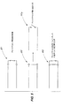
図2は、本発明の実施形態を利用することができる多数の金型枠組みのうちの1つの斜視図であり、耐火槽(illustrating refractory trough)135、金型入口134、金型出口136、通常はグラファイトリングである透過性周壁(permeable perimeter wall)130、水入口管(water inlet conduits)133、および金型枠組み131を示す。図2は金型出口136から出現する球状鋳造品137をさらに示す。
FIG. 2 is a perspective view of one of a number of mold frameworks in which embodiments of the present invention can be utilized: an illustrating
図2Aは、図2に記載されたものと同一のアイテムの斜視図であるが、鋳造品137の外殻で起こりがちな開口138を示しており、その結果、溶融金属139が通常の境界から脱出したり、「ブリードアウト」という用語で表される状態に至ったりする。当業者によって理解されるように、このような亀裂の外観とブリードアウト状況は変動する可能性があるため、図2Aに示されるように様々なブリードアウト状況が起こり得る。
FIG. 2A is a perspective view of the same item as described in FIG. 2, but showing an
鋳造環境は過酷であり、腐食性が高く、露出した構成要素の大幅な腐食や劣化を招きがちである。電気的および/または電子的構成要素はより正確で制御可能なセンサおよび検出器を提供し得るが、ときに過酷な鋳造環境の影響を受けやすい。したがって、本発明のいくつかの実施形態の目的の1つは、鋳造環境における腐食特性が向上したブリードアウト検出システムを提供することである。 The casting environment is harsh, highly corrosive and tends to cause significant corrosion and degradation of exposed components. Electrical and / or electronic components may provide more accurate and controllable sensors and detectors, but are sometimes susceptible to harsh casting environments. Accordingly, one of the objects of some embodiments of the present invention is to provide a bleedout detection system with improved corrosion characteristics in a casting environment.
図3は、4つの横列152と7つの縦列151の溶融金型を有する金型テーブル150の概略上面図であり、例示の2次元X−Y座標を示す。図3はx寸法153とy寸法154を有する金型テーブルを示す。
FIG. 3 is a schematic top view of a mold table 150 having four
交流電流/電圧などの振動信号または変動信号が直流または一定電流/電圧の代わりに使用され、平衡電流または電圧がゼロ周辺の範囲または許容範囲内で維持または均衡化される場合、ブリードアウト検出構成要素の腐食が低減、最小化、および/または排除されることが本発明の一部として判明した。また、本発明のいくつかの実施形態の目的の1つは、ゼロなどの所定値に、またはゼロ周辺の妥当な範囲内にほぼ均衡化される交流である平衡電流または交流電圧を供給する電気信号生成装置を提供することである。 Bleed-out detection configuration when vibration or fluctuation signals such as alternating current / voltage are used instead of direct current or constant current / voltage and the balanced current or voltage is maintained or balanced within a range around zero or tolerance It has been found as part of the present invention that element corrosion is reduced, minimized and / or eliminated. Another advantage of some embodiments of the present invention provides a balanced current or AC voltage to a predetermined value, or alternating current substantially balanced within a reasonable range around zero, such as zero An electrical signal generation device is provided.
図4は本発明の一実施形態のいくつかの主要構成要素を表す概略ブロック図であり、ブリードアウト検出システム177とブリードアウト検出制御システム178の実施形態を概略的に示す。プログラマブル制御装置180は信号生成装置181に出力を送信し、信号生成装置181からの入力を受信する。信号生成装置は、プログラマブル制御装置180に提供される対応情報と共に平衡電流を電流検出器183に送信する。図4は電流検出器183に動作可能に接続される導電性ブリードアウトセンサと警告構成要素179に動作可能に接続されるプログラマブル制御装置180とを示し、警告構成要素179は上記信号を受信し、その結果として警告、通知、データ、またはアクションを供給するように構成される警告/SCADAまたは/その他のシステム構成要素とすることができる。
FIG. 4 is a schematic block diagram representing some major components of one embodiment of the present invention, schematically illustrating an embodiment of a
図4Aは、導電性ブリードアウトセンサおよび/または導体182をプログラマブル制御装置180と信号生成装置181に接続できる例示の構造を示し、この構造においてプログラマブル制御装置180は電流検出器の機能を果たすことができる。図4Bは、どのようにプログラマブル制御装置190を導電性ブリードアウトセンサ191および電流検出器192に接続できるかを示し、この構造においてプログラマブル制御装置(プログラマブル論理制御装置または「PLC」とも称する)は信号生成機能を果たすこともできる。
FIG. 4A shows an exemplary structure in which a conductive bleedout sensor and / or
図4Cは、プログラマブル制御装置193またはプログラマブル論理制御装置(「PLC」)が動作可能に導電性ブリードアウトセンサ194に接続され、プログラマブル制御装置が電流検出機能と信号生成機能の両方を提供できる例示の構造を示す。当業者によって認識されるように、このようなシステム配置は、物理的および電子的に様々な形で構成することができる。
FIG. 4C illustrates an example in which a
図4Dは、警告システム185およびSCADAシステム186に動作可能に接続されるプログラマブル制御装置180の例示のブロック図または概略図である。図4Eは、どのようにプログラマブル制御装置180がユーザ通知システム196およびその他のシステム構成要素に動作可能に接続されるかを示す例示のブロック図である。図4Fは、ブリードアウト検出システムが動作可能に警告/SCADA/ユーザ通知または/その他のシステム199に接続される構造を示す概略ブロック図である。
FIG. 4D is an exemplary block diagram or schematic diagram of the
導電性ブリードアウトセンサが金型出口周辺部またはその近傍に構成される本発明の一実施形態のブリードアウト検出システムについて説明したが、当業者であれば、上記システムのその他の構成要素および素子は金型出口周辺部またはその近傍、あるいはその他の任意の位置に離隔して配置できることを認識しており、それらはすべて本発明の企図に含まれる。本発明の別の実施形態では、導電性ブリードアウトセンサは金型出口周辺部にまたはその近傍に配置することができる、あるいは導電性ブリードアウトセンサに対して同じまたは異なる位置に配置することができる。導電性ブリードアウトセンサは当業者によって認識されるように、開回路または閉回路を形成するように配置することができる、あるいは、ブリードアウト状況において、たとえば開回路から閉回路への変更、閉回路から開回路への変更、またはその他の方法によるインピーダンスの変更など、その他の特性を示すように変更し得る何らかの期待されるレベルの通常インピーダンスで動作するように設定することができる。図5は、通常開状態201にある、通常閉状態202にある、あるいは抵抗量によって示される量のインピーダンス203を伴って配置される導電性ブリードアウトセンサの概略図である。ブリードアウト状況は、正常な動作状況に基づく予測電流レベルを変更する場合がある。図5Aは、いかにして1つの電線205が金型207および金型アセンブリの導電性材料を利用して、ブリードアウト検出システム206またはブリードアウト検出回路との電気接続を行いその路を完成させるかを示す。当業者であれば、このような電気ループが電線または様々なその他の形状の導電性材料を用いて完成できることを認識するであろう。
Although the bleedout detection system according to an embodiment of the present invention in which the conductive bleedout sensor is configured in the vicinity of the mold outlet or in the vicinity thereof has been described, those skilled in the art will recognize other components and elements of the above system. It is recognized that they can be spaced apart at or near the mold exit periphery, or any other location, all of which are included in the contemplation of the present invention. In another embodiment of the present invention, conductive bleedout sensor is located in the same or different positions relative can be placed in a mold outlet peripheral portion or in the vicinity thereof, or conductive bleedout sensor that Can do. Conductive bleedout sensor as will be recognized by those skilled in the art, can be arranged so as to form an open circuit or closed circuit, or change in bleedout situations, for example from the open circuit to the closed circuit, the closed It can be set to operate at some expected level of normal impedance that can be changed to exhibit other characteristics, such as changing from circuit to open circuit, or changing impedance in other ways. Figure 5 is the normally
平衡電流という用語が本明細書で使用される際、平均基準線または点範囲辺りで振動または変動している電流を指すように幅広く解釈されることを目的とする。図6は包括的ではなく、起こり得る波形のいくつかの例を示しており、当業者が認識するように、そのような波形は様々な形で構成される、あるいは変動する。典型的な実施形態では、これはゼロの中間基準値周辺で平衡化される正弦波電流波201となるが、矩形波202またはその他の形状の波形を指すこともでき、矩形波、正弦波、またはその他の形状の波形内の波または領域は、平衡化されるために、形状、ピーク値、または期間が同一である必要はない。その他の例は、パルス波形203、平均の正側または負側の形状が同一であっても異なっていてもよい矩形波形204、三角波形205などである。波形の中央値または平均値は、当業者によって理解されるように限定ではなく、ゼロの値であってもなくてもよいDCバイアスまたはDC係数と称することもできる。当業者の場合、波形は時間に対する陽極または陰極値と記載することもある。
As used herein, the term balanced current is intended to be broadly interpreted to refer to a current that is oscillating or fluctuating around an average baseline or point range. FIG. 6 is not exhaustive and shows some examples of waveforms that may occur, and as those skilled in the art will appreciate, such waveforms may be configured or varied in various ways. In an exemplary embodiment, this will be a sinusoidal
信号生成装置という用語が本明細書で使用される際、最も幅広い意味で、電流、信号またはその他の電位、または導電エネルギーを、導電性ブリードアウトセンサ自体であっても、導電性ブリードアウトセンサと電気接続していてもよい導電性ブリードアウトセンサへ、および/または導電性ブリードアウトセンサを通じて供給、生成、または伝送する任意の装置または要素を指すために使用することができる。当業者によって理解されるように、ブリードアウト信号生成装置の位置は物理的にも電子的にも変動させることができ、別個に組み立てられた電子ユニット、制御装置自体の一部、またはブリードアウト検出システムによって使用される電気信号を供給するように構成された構成要素として配置することができる。本発明の企図の一部では、信号生成装置からの周波数の使用は広範な範囲の値全体にわたって採用することができ、使用可能な周波数は通常、導電性ブリードアウトセンサと冷却液の相互作用のインピーダンスから生じ得る所望の特性や結果的な腐食低減などの電子的利得に応じて選択される。同様に、本発明の実施形態は、上述したような信号生成装置によって提供される様々な交流波形と共に使用することができる。 When the term signal generator is used herein, in the broadest sense, the current, signal or other potential or a conductive energy, be a conductive bleedout sensor itself, and the conductive bleed out sensor to the electrical connection and have good conductive bleedout sensor also, and / or conductive bleedout supplied through sensors, generates, or may be used to refer to any device or element to be transmitted. As will be appreciated by those skilled in the art, the position of the bleedout signal generator can be varied both physically and electronically, such as a separately assembled electronic unit, part of the controller itself, or bleedout detection. It can be arranged as a component configured to provide an electrical signal for use by the system. In some contemplated of the present invention, use of the frequency from the signal generator may be employed over the entire value of the broad range, usable frequency usually interaction conductive bleedout sensors and the coolant Depending on the desired characteristics that can result from the current impedance and the electronic gain such as the resulting corrosion reduction. Similarly, embodiments of the present invention can be used with various AC waveforms provided by a signal generator as described above.
鋳造冷却工程の一部として使用される液体の導電性に応じて、平衡電流を供給する信号生成装置の出力は、結果として生じる電流レベルの最適電位を得るために調節を要する。企図される本発明の実施形態では、信号生成装置の出力は手動で調節する、プログラマブル制御装置を通じて特定値に設定する、あるいはプログラマブル制御装置を介して自動的に調節することができる。冷却液の導電性は、一方が負であり他方が正である2つのリングにわたって外側に延びるために腐食に影響を及ぼし、冷却液は電荷を通過させて腐食を引き起こすのに十分な導電性または能力を有する。 Depending on the conductivity of the liquid used as part of the casting cooling process, the output of the signal generator that supplies the balanced current needs to be adjusted to obtain the optimum potential of the resulting current level. In contemplated embodiments of the invention, the output of the signal generator can be adjusted manually, set to a specific value through a programmable controller, or automatically adjusted through the programmable controller. The conductivity of the coolant affects corrosion because it extends outward over two rings, one negative and the other positive, and the coolant is sufficiently conductive to pass charge or cause corrosion. Have the ability.
電解腐食電池では、イオンは構成要素のうちの1つから除去され、溶液内に伝送され、その他の構成要素上に付着する。我々はACを用いることによって電気分解反応を有功に中性化することで、結果的に生じる腐食を低減または排除する。 In electrolytic corrosion cells, ions are removed from one of the components, transmitted into solution, and deposited on the other component. We effectively neutralize the electrolysis reaction by using AC to reduce or eliminate the resulting corrosion.
導電性ブリードアウトセンサという用語が本明細書で使用される際、たとえば、限定するものではないが、導電性材料間の意図的な通常動作レベルのインピーダンスまたはコンダクタンスを有する導電路を生成する、金属板、配線、またはその他の材料など、本発明の企図に含まれる導電性の材料、素子、または構成要素の多数の様々な構成のうち任意の1つとすることができる。導電性材料間のインピーダンスまたはコンダクタンスのレベルは、当業者にとって既知な様々な形で設定することができる。本発明の企図に含まれる導電性ブリードアウトセンサのいくつかの実施形態は、導電性金属部間に配置される導電性物質、抵抗またはリアクタンスを提供する導電性材料間の構成要素、または図5に示されるようなインピーダンスのレベルを形成するいくつかの組み合わせを含むことができる。 When the term conductive bleedout sensor is used herein, for example, but not limited to, a metal that produces a conductive path having an intentional normal operating level impedance or conductance between conductive materials It can be any one of a number of different configurations of conductive materials, elements, or components included in the contemplation of the present invention, such as plates, wiring, or other materials. The level of impedance or conductance between the conductive materials can be set in various ways known to those skilled in the art. Some embodiments of the conductive bleed out sensor included in the contemplation of the present invention, conductive material disposed between the conductive metal section, the components between the conductive material to provide a resistance or reactance, or drawing, Several combinations that form the level of impedance as shown in FIG.
図7は、金型221の底部と装着可能な板222(導電性ブリードアウトセンサ)との間に絶縁層220を使用する本発明の一実施形態を示す。本実施形態では、抵抗またはその他のインピーダンス構成要素223は、絶縁層220を迂回または通過することによって設置される。板および金型本体は、金型本体に対する瞬時の交流正電圧と負電圧が得られる際に見られるものの中で電気接続されている。冷却液および/または溶融金属225により提示され得るインピーダンスレベルも図7に示す。
Figure 7 shows an embodiment of the present invention to use the insulating
別の実施形態は図8に示されるような金型221の底部に装着される2つの板222a、222bを使用し、板の間の絶縁層220と板どうしをつなぐ抵抗223が導入されている。板は2つの板間の瞬時の交流正電圧と負電圧が得られる際に見られるものの中で電気接続されている。冷却液および/または溶融金属225により提示され得るインピーダンスレベルも図8に示す。企図される電流路は、導電性ブリードアウトセンサ又は導体路への2つまたはそれ以上の電線の実施形態も含むことによって、信号生成装置、PLC制御装置、および/または電流検出器への接続も可能とする。導電性ブリードアウトセンサへの1つの電線を使用し、金型と組み立てられた金型装置とが電流路の1つを提供する別の実施形態も企図される。
Another embodiment uses two plates 222a and 222b attached to the bottom of the
制御装置またはプログラマブル制御装置という用語が本明細書で使用される際、図9および9Aで示されるような主要構成要素ハウジング(main component housing)240から成るプログラマブル論理制御装置、または図9および9Bに示されるような主要構成要素ハウジング240と遠隔システム構成要素241との組み合わせを限定なく含む任意数の異なる種類の制御構造を指すことができる。プログラマブル制御装置は、調節可能な構成要素を含む制御回路、または所望の制御機能を提供するように構成された配線済みの電子機器を指すことができる。当業者であれば、プログラマブル論理制御装置、PLCの使用が一般的であるが、制御装置の設定において唯一の選択肢ではないことを認識するであろう。
As the term controller or programmable controller is used herein, a programmable logic controller comprising a
本発明の実施形態は電子電流検出器を含む、あるいは利用するが、様々な電流または電位レベル、モジュール、またはプログラマブル制御装置の一部とみなされる構成要素に直面するときに状態を切り換える、あるいはその他の形で変更する構成要素(複数可)を伴うよう設計された回路、あるいは様々なレベルの電位または電流が存在する際に出力を変更するように構成されるその他の材料を含むことができることに留意すべきである。図10は、導電性ブリードアウトセンサ261、電流検出器262、およびプログラマブル制御装置263間の関係の一実施形態を示す概略図である。図示される一実施形態では、動作時の電流検出器262は導電性ブリードアウトセンサ261を通じた電流の流れに基づき電流または電位を受信し、手動で設定された閾値または制御装置からの入力に応じて電流を処理し、閾値レベルに応じて電子電流検出器からの出力をプログラマブル制御装置に供給するように配置される。本実施形態での閾値ラッチは、電流閾値レベルを検出する際にラッチする内部スイッチ264によって表される。よって、プログラマブル制御装置263への電流検出器の出力は現状に応じて変動し、電流検出器の状態に関する情報をプログラマブル制御装置に提供する。本発明に関して検討されるように、閾値という用語は、電流検出器出力の変更をトリガするのに十分な任意の正または負の値を指すことができる。当業者によって既知なように、回路構造に応じて、上記閾値は様々な構成要素、調節可能な構成要素の使用、あるいはプログラマブル制御装置の設定変更によって調節可能とすることができる。上述した通り、当業者によって認識されるように、電流検出器は様々な位置に物理的および電子的に配置することができる。このように考えられる実施形態は、様々な電流レベルに直面する際に状態を変更するように別様に構成された、別個に組み立てられた電子ユニット、制御装置自体の一部、または構成要素の構造を取ることができる。
Embodiments of the present invention include or utilize electronic current detectors, but switch states when facing various current or potential levels, modules, or components that are considered part of a programmable controller, or otherwise Can include circuits designed with component (s) that change in the form of, or other materials configured to change output in the presence of various levels of potential or current It should be noted. Figure 10 is a conductive bleed out
当業者であれば、プログラマブル制御装置は動作時のブリードアウト検出システムのその他の素子と関連する各種機能に合わせて構成できると理解するであろう。本発明に関して想定されるプログラマブル制御装置の機能の実施形態は、独立して、または個別に、または機能の一部または全部の様々な組み合わせで使用することのできるいくつかの機能を含むがそれらに限定されない。プログラマブル制御装置が受け取ることのできる例示の入力はすべての可能な考えられる入力の包括的リストではなく、電流検出器からの信号、信号生成装置によって提供される波形の大きさ、導電性ブリードアウトセンサが情報源である金型(複数可)のIDのうち1つまたはそれ以上を含むことができる。当業者によって認識されるように、システムの他の部分からの入力は実際の電気信号であっても、電気信号の不在であってもよい。プログラマブル制御装置にとって企図される出力も包括的リストではなく、大きさ、周波数、および/または波形などの信号の特徴に関する信号生成装置へのコマンド、および電流検出器状態に基づく電流検出器へのリセットコマンドを含む。動作中、電流検出器は上述の閾値に達する可能性がある。プログラマブル制御装置は、閾値に到達することによって設定される電流検出器の状態を変更するように使用することができる。当業者によって既知なように、プログラマブル制御装置は、信号を無視するとき、あるいは信号を利用して他の工程を開始するとき電流検出器に応答する、および/または電流検出器をリセットするように配置することができる。本発明の一部として企図されるように、別の可能なプログラマブル制御装置出力は、ブリードアウト状況に応答して、警告またはその他の通知をオペレータに、あるいはコマンドをその他の装置に提供するように構成することができる。「通知」という用語はこれらの警告機能のいずれを指すためにも使用され、情報を提供するか、あるいは追加の工程ステップとのリンクを提供する。 One skilled in the art will appreciate that the programmable controller can be configured for various functions associated with other elements of the bleedout detection system during operation. Embodiments of programmable controller functionality envisioned with respect to the present invention include several functions that can be used independently or individually or in various combinations of some or all of the functions. It is not limited. The exemplary inputs that can be received by the programmable controller are not a comprehensive list of all possible inputs, but the signals from the current detector, the magnitude of the waveform provided by the signal generator, the conductive bleed out sensor Sa can include one or more of the ID of the mold is the information source (s). As will be appreciated by those skilled in the art, inputs from other parts of the system may be actual electrical signals or in the absence of electrical signals. The output intended for the programmable controller is also not a comprehensive list, but commands to the signal generator regarding signal characteristics such as magnitude, frequency, and / or waveform, and reset to the current detector based on current detector status Contains commands. In operation, the current detector may reach the above threshold. The programmable controller can be used to change the state of the current detector that is set by reaching the threshold. As known by those skilled in the art, the programmable controller is responsive to the current detector and / or resets the current detector when ignoring the signal or when utilizing the signal to initiate another process. Can be arranged. As contemplated as part of the present invention, another possible programmable controller output may provide warnings or other notifications to the operator or commands to other devices in response to a bleedout situation. Can be configured. The term “notification” is used to refer to any of these alert functions and provides information or links to additional process steps.
本発明の各種実施形態で企図される別の特徴は、鋳造前、鋳造動作中、またはユーザの所望する任意の時点で導電性ブリードアウトセンサ電流路の状態および操作可能性を判定する検査機能を含む。当業者にしたがって、本プロセスは様々な形で構成することができるが、本発明で企図されるいくつかの実施形態では、プログラマブル制御装置は、電流検出器への電流が電流検出器の閾値設定を満たすように、大きさ、周波数、または波形など、導電性ブリードアウトセンサに提供される信号を変更するべく信号生成装置に命じる。それにしたがって電流検出器はプログラマブル制御装置の情報または情報の欠如を送信し、その設定に応じてプログラマブル制御装置は導電性ブリードアウトセンサの動作状態および電気接続状態を認識することができる。可能なプログラマブル制御装置出力に関して上述したように、その後、プログラマブル制御装置は、信号生成装置の正常な動作レベルへの転送、閾値との関係における電流検出器のリセット機能のうち1つまたはそれ以上のために使用することができる。また、プログラマブル制御装置は、検査工程中または検査工程外で受信された、あるいは受信されなかった信号を認識するように構成することができる。 Another feature contemplated in the various embodiments of the present invention, the casting before the casting operation or during testing function to determine the status and operability of the conductive bleedout sensor current path at any time desired by the user, including. According to those skilled in the art, the process can be configured in a variety of ways, but in some embodiments contemplated by the present invention, the programmable controller can cause the current to the current detector to set the threshold of the current detector. to meet mandates magnitude, frequency, or the like waveform, the signal generator in order to modify the signals provided to the conductive bleed out sensor. Accordingly the current detector sends a lack of information or information of the programmable controller, the programmable controller in accordance with the setting can recognize the operating state and the electrical connection state of the conductive bleed out sensor. As described above with respect to possible programmable controller outputs, the programmable controller may then transfer one or more of the following: transferring the signal generator to a normal operating level, resetting the current detector in relation to a threshold value. Can be used for. In addition, the programmable control device can be configured to recognize a signal received or not received during or outside the inspection process.
当業者によって理解されるように、電気絶縁は固体、液体、気体、またはその他の形の電気絶縁を指すことができる。同様に理解されるように、波形の大きさは大きく変動する可能性があるが、理想的には安全性と回路設計のために妥当に低いものの所望の機能を果たすのに十分なレベルで保たれる。 As will be appreciated by those skilled in the art, electrical insulation can refer to solid, liquid, gas, or other forms of electrical insulation. As can also be seen, the magnitude of the waveform can vary greatly, but ideally it is reasonably low for safety and circuit design, but kept at a level sufficient to perform the desired function. Be drunk.
Claims (30)
鋳型枠組みと、
金型入口と金型空隙周辺部を有する金型出口とを備えた溶融金属鋳型と、
ブリードアウト検出システムであって、
前記金型出口周辺部またはその近傍で他の構成要素に電気的に接続される導電性ブリードアウトセンサと、
前記導電性ブリードアウトセンサに平衡電流を供給する信号生成装置と、
前記導電性ブリードアウトセンサのインピーダンスを監視する電流検出器と、
を有するブリードアウト検出システムと、
前記ブリードアウト検出システムから前記導電性ブリードアウトセンサの状態に関する電気信号を受信するプログラマブル制御装置と、
を備える半連続または連続鋳型。 A semi-continuous or continuous mold with a bleed-out detection system,
Mold framework,
A molten metal mold with a mold inlet and a mold outlet having a mold cavity periphery; and
A bleedout detection system,
A conductive bleed-out sensor that is electrically connected to other components at or near the mold outlet periphery; and
A signal generator for supplying a balanced current to the conductive bleedout sensor;
A current detector for monitoring the impedance of the conductive bleedout sensor;
A bleed-out detection system,
A programmable controller that receives electrical signals relating to the state of the conductive bleedout sensor from the bleedout detection system;
With semi-continuous or continuous mold.
前記ブリードアウト検出システムのユーザへの通知または警告、および
ブリードアウト作用を含むその他の装置へのコマンド
を備える出力を提供するよう構成された請求項1に記載のブリードアウト検出システムを有する半連続または連続鋳型。 The programmable controller with respect to other system components,
The bleedout detection system of claim 1 configured to provide an output comprising a notification or warning to a user of the bleedout detection system and a command to other devices including a bleedout action or Continuous mold.
金型出口周辺部またはその近傍に構成される導電性ブリードアウトセンサと、
交流電流である平衡電流を前記導電性ブリードアウトセンサに供給する信号生成装置と、
前記ブリードアウト検出システムからの電気信号を受信するよう構成されたプログラマブル制御装置と、
を備えるブリードアウト検出システム。 A bleedout detection system,
A conductive bleed-out sensor configured at or near the mold outlet; and
A signal generator for supplying an equilibrium current, which is an alternating current, to the conductive bleedout sensor;
A programmable controller configured to receive an electrical signal from the bleedout detection system;
A bleed-out detection system.
前記導電性ブリードアウトセンサと前記金型出口周辺部間の設定インピーダンスと、
をさらに備え、
金型テーブルアセンブリが、前記導電性ブリードアウトセンサと前記金型出口周辺部の間に電気的に位置している請求項14に記載のブリードアウト検出システム。 A wire to the conductive bleed-out sensor;
A set impedance between the conductive bleed-out sensor and the mold outlet periphery ,
Further comprising a,
The bleed-out detection system according to claim 14 , wherein a mold table assembly is electrically located between the conductive bleed-out sensor and the mold outlet periphery .
前記導電性ブリードアウトセンサが、
設定量のインピーダンスによって隔離される2片の導電性材料と、
金型と電気接続する導電性材料片のうち1つと、
を備え、
金型テーブルアセンブリが、前記導電性ブリードアウトセンサと前記金型出口周辺部の間に電気的に位置している請求項14に記載のブリードアウト検出システム。 Further comprising an electric wire of the conductive bleed-out sensor,
The conductive bleedout sensor is
Two pieces of conductive material separated by a set amount of impedance;
One of the pieces of conductive material electrically connected to the mold ;
Equipped with a,
The bleed-out detection system according to claim 14 , wherein a mold table assembly is electrically located between the conductive bleed-out sensor and the mold outlet periphery .
導電性ブリードアウトセンサと、
前記導電性構成要素と、交流電流を生成する信号生成装置及び電流検出器を備える回路との間の設定量のインピーダンスと、
を備えるブリードアウト検出システム。 Conductive components configured in the vicinity of the mold outlet or in the vicinity thereof; and
A conductive bleedout sensor;
A set amount of impedance between the conductive component and a circuit comprising a signal generator and a current detector for generating an alternating current; and
A bleed-out detection system.
抵抗と、
前記導電性材料と前記金型出口周辺部またはその近傍の導電性材料との電気絶縁と、
を備える請求項17に記載のブリードアウト検出システム。 The impedance is
Resistance,
Electrical insulation between the conductive material and the periphery of the mold outlet or the conductive material in the vicinity thereof;
The bleed-out detection system according to claim 17.
抵抗を伴い相互に電気的に接続される2つの金属板を備え、
前記2つの金属板が電気絶縁によって別様に隔離される請求項17に記載のブリードアウト検出システム。 The conductive material is
Comprising two metal plates electrically connected to each other with resistance;
The bleed-out detection system according to claim 17, wherein the two metal plates are separately separated by electrical insulation.
金型出口周辺部またはその近傍に構成される導電性ブリードアウトセンサを設けることと、
前記導電性ブリードアウトセンサに、交流電流である平衡電流を供給する信号生成装置を設けることと、
前記導電性ブリードアウトセンサの状態に関する電気信号を受信するプログラマブル制御装置を設けることと、
を備える方法。 A method for detecting a bleed-out situation in a semi-continuous or continuous molten mold,
And providing a conductive bleed out sensor configured on the periphery or near the mold outlet,
Providing the conductive bleed-out sensor with a signal generator for supplying an equilibrium current that is an alternating current;
Providing a programmable controller for receiving electrical signals relating to the state of the conductive bleed-out sensor;
A method comprising:
交流電流出力の大きさを変更するコマンドを前記信号生成装置に送信するプログラマブル制御装置を設けることと、
設定電流レベルの検出時に前記プログラマブル制御装置に出力を電気的に送信する電流検出器を設けることと、
検査工程の結果として前記電流検出器から受信した信号を認識するように前記プログラマブル制御装置を設定することと、
によって実行される請求項25に記載の半連続または連続溶融金型におけるブリードアウト状況の検出方法。 Inspection process
Providing a programmable control device for transmitting a command to change the magnitude of the alternating current output to the signal generating device;
Providing a current detector that electrically transmits an output to the programmable controller upon detection of a set current level;
Setting the programmable controller to recognize a signal received from the current detector as a result of an inspection process;
26. The method for detecting a bleed-out state in a semi-continuous or continuous molten mold according to claim 25, which is performed by:
Applications Claiming Priority (3)
| Application Number | Priority Date | Filing Date | Title |
|---|---|---|---|
| US13/385,421 | 2012-02-17 | ||
| US13/385,421 US8408280B1 (en) | 2012-02-17 | 2012-02-17 | Bleedout detection system |
| PCT/US2012/066133 WO2013122640A1 (en) | 2012-02-17 | 2012-11-20 | Bleedout detection system |
Publications (2)
| Publication Number | Publication Date |
|---|---|
| JP2015514580A JP2015514580A (en) | 2015-05-21 |
| JP6195580B2 true JP6195580B2 (en) | 2017-09-13 |
Family
ID=47989684
Family Applications (1)
| Application Number | Title | Priority Date | Filing Date |
|---|---|---|---|
| JP2014557626A Active JP6195580B2 (en) | 2012-02-17 | 2012-11-20 | Bleed-out detection system |
Country Status (14)
| Country | Link |
|---|---|
| US (1) | US8408280B1 (en) |
| EP (1) | EP2814629B1 (en) |
| JP (1) | JP6195580B2 (en) |
| KR (1) | KR101655750B1 (en) |
| CN (1) | CN104114301B (en) |
| AU (1) | AU2012369954B2 (en) |
| BR (1) | BR112014019934B1 (en) |
| CA (1) | CA2862809C (en) |
| IN (1) | IN2014MN01601A (en) |
| MX (1) | MX346651B (en) |
| NO (1) | NO2898032T3 (en) |
| RU (1) | RU2594924C2 (en) |
| TR (1) | TR201808248T4 (en) |
| WO (1) | WO2013122640A1 (en) |
Families Citing this family (2)
| Publication number | Priority date | Publication date | Assignee | Title |
|---|---|---|---|---|
| CN109954854B (en) * | 2019-04-10 | 2021-02-26 | 中冶赛迪工程技术股份有限公司 | Method and device for monitoring breakout of crystallizer of continuous casting machine, storage medium and electronic terminal |
| CN111366307B (en) * | 2020-03-05 | 2022-03-11 | 欣旺达电动汽车电池有限公司 | Liquid leakage detection device, method, storage medium and computer equipment |
Family Cites Families (15)
| Publication number | Priority date | Publication date | Assignee | Title |
|---|---|---|---|---|
| JPS5148575Y2 (en) * | 1971-05-21 | 1976-11-24 | ||
| US3817311A (en) * | 1972-10-13 | 1974-06-18 | Ibm | Method and apparatus for controlling a continuous casting machine |
| JPS59125252A (en) * | 1982-12-29 | 1984-07-19 | Nippon Kokan Kk <Nkk> | Predicting method of breakout in continuous casting |
| US4712602A (en) * | 1986-09-11 | 1987-12-15 | Hazelett Strip-Casting Corporation | Pool-level sensing probe and automatic level control for twin-belt continuous metal casting machines |
| US4936374A (en) * | 1988-11-17 | 1990-06-26 | The United States Of America As Represented By The United States Department Of Energy | Sidewall containment of liquid metal with horizontal alternating magnetic fields |
| JPH07108359A (en) * | 1993-10-08 | 1995-04-25 | Aichi Steel Works Ltd | Device for monitoring friction force between continuous casting mold and cast slab |
| US5697423A (en) * | 1994-03-30 | 1997-12-16 | Lauener Engineering, Ltd. | Apparatus for continuously casting |
| AUPN633295A0 (en) * | 1995-11-02 | 1995-11-23 | Comalco Aluminium Limited | Bleed out detector for direct chill casting |
| US5918473A (en) * | 1997-05-09 | 1999-07-06 | Alcan International Limited | Method and apparatus for measuring quenchant properties of coolants |
| US6446703B1 (en) * | 1998-09-30 | 2002-09-10 | Nichols Aluminum-Golden, Inc. | Method and apparatus for improving the quality of continuously cast metal |
| JP4220094B2 (en) * | 1999-04-05 | 2009-02-04 | 三菱電機株式会社 | Power semiconductor module |
| US6215290B1 (en) * | 1999-11-15 | 2001-04-10 | Semtech Corporation | Multi-phase and multi-module power supplies with balanced current between phases and modules |
| JP2006507950A (en) * | 2002-11-29 | 2006-03-09 | アーベーベー・アーベー | Control system, computer program product, apparatus and method |
| US7296613B2 (en) * | 2003-06-13 | 2007-11-20 | Wagstaff, Inc. | Mold table sensing and automation system |
| DE102005044831A1 (en) * | 2005-09-20 | 2007-03-22 | Siemens Ag | Method and device for monitoring an electric heater |
-
2012
- 2012-02-17 US US13/385,421 patent/US8408280B1/en active Active
- 2012-11-20 CA CA2862809A patent/CA2862809C/en active Active
- 2012-11-20 WO PCT/US2012/066133 patent/WO2013122640A1/en active Application Filing
- 2012-11-20 RU RU2014137451/02A patent/RU2594924C2/en active
- 2012-11-20 BR BR112014019934-5A patent/BR112014019934B1/en active IP Right Grant
- 2012-11-20 JP JP2014557626A patent/JP6195580B2/en active Active
- 2012-11-20 EP EP12868796.9A patent/EP2814629B1/en active Active
- 2012-11-20 IN IN1601MUN2014 patent/IN2014MN01601A/en unknown
- 2012-11-20 MX MX2014009452A patent/MX346651B/en active IP Right Grant
- 2012-11-20 KR KR1020147022736A patent/KR101655750B1/en active IP Right Grant
- 2012-11-20 AU AU2012369954A patent/AU2012369954B2/en active Active
- 2012-11-20 TR TR2018/08248T patent/TR201808248T4/en unknown
- 2012-11-20 CN CN201280069879.4A patent/CN104114301B/en active Active
-
2013
- 2013-09-20 NO NO13774370A patent/NO2898032T3/no unknown
Also Published As
| Publication number | Publication date |
|---|---|
| CN104114301B (en) | 2017-08-04 |
| TR201808248T4 (en) | 2018-07-23 |
| CN104114301A (en) | 2014-10-22 |
| RU2594924C2 (en) | 2016-08-20 |
| BR112014019934A8 (en) | 2017-07-11 |
| WO2013122640A1 (en) | 2013-08-22 |
| MX2014009452A (en) | 2014-11-12 |
| JP2015514580A (en) | 2015-05-21 |
| AU2012369954A1 (en) | 2014-09-04 |
| AU2012369954B2 (en) | 2016-07-28 |
| CA2862809A1 (en) | 2013-08-22 |
| BR112014019934B1 (en) | 2019-02-26 |
| US8408280B1 (en) | 2013-04-02 |
| EP2814629A1 (en) | 2014-12-24 |
| RU2014137451A (en) | 2016-04-10 |
| KR20140116931A (en) | 2014-10-06 |
| KR101655750B1 (en) | 2016-09-08 |
| EP2814629B1 (en) | 2018-03-14 |
| NZ628746A (en) | 2016-09-30 |
| CA2862809C (en) | 2018-01-16 |
| IN2014MN01601A (en) | 2015-05-15 |
| NO2898032T3 (en) | 2018-03-17 |
| EP2814629A4 (en) | 2015-10-21 |
| MX346651B (en) | 2017-03-28 |
| BR112014019934A2 (en) | 2017-06-20 |
Similar Documents
| Publication | Publication Date | Title |
|---|---|---|
| EP2857121B1 (en) | Continuous casting molding device with stirring device | |
| JP6195580B2 (en) | Bleed-out detection system | |
| KR890001609B1 (en) | Molten metal level control in continuous casting | |
| EP2667986A1 (en) | Coolant control and wiper system for a continuous casting molten metal mold | |
| JP4387412B2 (en) | Mold stand detection automation system | |
| JP2010501351A (en) | Gas flow control system for molten metal molds with permeable perimeter walls | |
| CN104532334A (en) | Plating line current abnormality detection and current regulation method and device | |
| NZ628746B2 (en) | Bleedout detection system | |
| JP4211548B2 (en) | Molten metal leak detection method in continuous casting of aluminum | |
| EP1155762B1 (en) | Control device and method to stop a molten metal flow, in the event a bleedout is detected during continuous casting | |
| KR20230003127A (en) | Casting environment monitoring | |
| Karimi-Sibaki et al. | CFD Modeling of the electrode change during the ESR process | |
| WO2022020708A1 (en) | System and method for monitoring metal level during casting | |
| JP2001115219A (en) | Electrode weighing stab | |
| AU781417B2 (en) | A continuous casting mold plug activation and bleedout detection system | |
| JP2010005645A (en) | Mold for casting anode for electrolysis | |
| JP2006075840A (en) | Vertical type continuous casting apparatus for metal |
Legal Events
| Date | Code | Title | Description |
|---|---|---|---|
| A977 | Report on retrieval |
Free format text: JAPANESE INTERMEDIATE CODE: A971007 Effective date: 20150903 |
|
| A131 | Notification of reasons for refusal |
Free format text: JAPANESE INTERMEDIATE CODE: A131 Effective date: 20151006 |
|
| A601 | Written request for extension of time |
Free format text: JAPANESE INTERMEDIATE CODE: A601 Effective date: 20160106 |
|
| A601 | Written request for extension of time |
Free format text: JAPANESE INTERMEDIATE CODE: A601 Effective date: 20160203 |
|
| A601 | Written request for extension of time |
Free format text: JAPANESE INTERMEDIATE CODE: A601 Effective date: 20160307 |
|
| A521 | Request for written amendment filed |
Free format text: JAPANESE INTERMEDIATE CODE: A523 Effective date: 20160405 |
|
| A131 | Notification of reasons for refusal |
Free format text: JAPANESE INTERMEDIATE CODE: A131 Effective date: 20160913 |
|
| A601 | Written request for extension of time |
Free format text: JAPANESE INTERMEDIATE CODE: A601 Effective date: 20161212 |
|
| A601 | Written request for extension of time |
Free format text: JAPANESE INTERMEDIATE CODE: A601 Effective date: 20170210 |
|
| A521 | Request for written amendment filed |
Free format text: JAPANESE INTERMEDIATE CODE: A523 Effective date: 20170313 |
|
| TRDD | Decision of grant or rejection written | ||
| A01 | Written decision to grant a patent or to grant a registration (utility model) |
Free format text: JAPANESE INTERMEDIATE CODE: A01 Effective date: 20170718 |
|
| A61 | First payment of annual fees (during grant procedure) |
Free format text: JAPANESE INTERMEDIATE CODE: A61 Effective date: 20170815 |
|
| R150 | Certificate of patent or registration of utility model |
Ref document number: 6195580 Country of ref document: JP Free format text: JAPANESE INTERMEDIATE CODE: R150 |
|
| R250 | Receipt of annual fees |
Free format text: JAPANESE INTERMEDIATE CODE: R250 |
|
| R250 | Receipt of annual fees |
Free format text: JAPANESE INTERMEDIATE CODE: R250 |
|
| R250 | Receipt of annual fees |
Free format text: JAPANESE INTERMEDIATE CODE: R250 |
|
| R250 | Receipt of annual fees |
Free format text: JAPANESE INTERMEDIATE CODE: R250 |