KR20140090717A - Fixing apparatus for steering column in vehicles - Google Patents
Fixing apparatus for steering column in vehicles Download PDFInfo
- Publication number
- KR20140090717A KR20140090717A KR1020120151376A KR20120151376A KR20140090717A KR 20140090717 A KR20140090717 A KR 20140090717A KR 1020120151376 A KR1020120151376 A KR 1020120151376A KR 20120151376 A KR20120151376 A KR 20120151376A KR 20140090717 A KR20140090717 A KR 20140090717A
- Authority
- KR
- South Korea
- Prior art keywords
- steering column
- mounting bracket
- sliding groove
- vehicle
- sliding
- Prior art date
Links
Images

Classifications
-
- B—PERFORMING OPERATIONS; TRANSPORTING
- B62—LAND VEHICLES FOR TRAVELLING OTHERWISE THAN ON RAILS
- B62D—MOTOR VEHICLES; TRAILERS
- B62D1/00—Steering controls, i.e. means for initiating a change of direction of the vehicle
- B62D1/02—Steering controls, i.e. means for initiating a change of direction of the vehicle vehicle-mounted
- B62D1/16—Steering columns
- B62D1/20—Connecting steering column to steering gear
-
- B—PERFORMING OPERATIONS; TRANSPORTING
- B62—LAND VEHICLES FOR TRAVELLING OTHERWISE THAN ON RAILS
- B62D—MOTOR VEHICLES; TRAILERS
- B62D1/00—Steering controls, i.e. means for initiating a change of direction of the vehicle
- B62D1/02—Steering controls, i.e. means for initiating a change of direction of the vehicle vehicle-mounted
- B62D1/16—Steering columns
- B62D1/18—Steering columns yieldable or adjustable, e.g. tiltable
- B62D1/19—Steering columns yieldable or adjustable, e.g. tiltable incorporating energy-absorbing arrangements, e.g. by being yieldable or collapsible
- B62D1/195—Yieldable supports for the steering column
-
- B—PERFORMING OPERATIONS; TRANSPORTING
- B60—VEHICLES IN GENERAL
- B60Y—INDEXING SCHEME RELATING TO ASPECTS CROSS-CUTTING VEHICLE TECHNOLOGY
- B60Y2300/00—Purposes or special features of road vehicle drive control systems
- B60Y2300/08—Predicting or avoiding probable or impending collision
- B60Y2300/097—Vehicle operation after collision
Abstract
Description
본 발명은 차량의 스티어링 컬럼용 고정장치에 관한 것으로서, 특히, 차량 충돌 후에 스티어링 컬럼의 처짐 및 회전을 방지할 수 있는 차량의 스티어링 컬럼용 고정장치에 관한 것이다.
The present invention relates to a fixing device for a steering column of a vehicle, and more particularly to a fixing device for a steering column of a vehicle capable of preventing deflection and rotation of the steering column after a vehicle collision.
일반적인 스티어링 시스템(steering system)은 운전자가 발생시킨 회전력을 차량의 바퀴에 전달하여 차량의 진행방향을 바꾼다.A typical steering system transmits the rotational force generated by the driver to the wheels of the vehicle to change the direction of the vehicle.
이러한 스티어링 시스템은 운전석에 설치되는 스티어링 휠(steering wheel)과, 스티어링 휠에 연결되는 스티어링 샤프트(steering shaft) 및 스티어링 샤프트의 외측을 감싸며 설치되는 스티어링 컬럼(steering column)을 포함한다.Such a steering system includes a steering wheel installed on a driver's seat, a steering shaft connected to the steering wheel, and a steering column surrounding the outside of the steering shaft.
스티어링 컬럼은 운전자의 다양한 신체 조건에 적합하게 변화될 수 있도록, 틸트 기능과 높이 조절 기능을 갖는다.
The steering column has a tilt function and a height adjustment function so that it can be changed to suit various physical conditions of the driver.
본 발명의 배경기술은 대한민국 공개특허공보 2010??0031944호(2010.03.25 공개, 발명의 명칭: 스티어링 컬럼)에 개시되어 있다.
BACKGROUND ART [0002] The background art of the present invention is disclosed in Korean Patent Publication No. 20100031944 (published on Mar. 25, 2010, entitled " Steering Column ").
일반적인 차량의 스티어링 컬럼은 스티어링 컬럼을 지지하는 마운팅 브래킷이 차량 충돌 시에 차체에서 분리되기 때문에 차량 충돌이 발생되면 스티어링 컬럼이 하측으로 처지거나 회전되면서 충돌 성능이 저하되는 문제점이 있다.A steering column of a general vehicle has a problem that the collision performance is deteriorated when the steering column is sagged or rotated downward when a vehicle collision occurs because the mounting bracket supporting the steering column is separated from the vehicle body at the time of a vehicle collision.
따라서 이를 개선할 필요성이 요청된다.Therefore, there is a need for improvement.
본 발명은 차량 충돌 후에 스티어링 컬럼의 처짐 및 회전을 방지할 수 있는 차량의 스티어링 컬럼용 고정장치를 제공하는데 그 목적이 있다.
An object of the present invention is to provide a fixing device for a steering column of a vehicle which can prevent deflection and rotation of the steering column after a vehicle collision.
본 발명은, 차체에 고정되는 마운팅 브래킷; 스티어링 컬럼을 상하 방향으로 유동 가능하게 지지하는 틸트 브래킷; 상기 틸트 브래킷을 상기 마운팅 브래킷에 전후 방향으로 슬라이딩 가능하게 연결하는 지지부를 포함하는 것을 특징으로 한다.The present invention provides a vehicle comprising: a mounting bracket fixed to a vehicle body; A tilt bracket for supporting the steering column so as to be vertically movable; And a support for slidably connecting the tilt bracket to the mounting bracket in the forward and backward directions.
또한, 본 발명의 상기 지지부는, 상기 마운팅 브래킷에 형성되고, 전후 방향으로 길게 형성되는 슬라이딩홈부; 및 상기 슬라이딩홈부에 유동 가능하게 삽입되도록 상기 틸트 브래킷에 형성되는 슬라이딩돌기를 포함하는 것을 특징으로 한다.Further, the support portion of the present invention may include: a sliding groove portion formed in the mounting bracket and elongated in the front-rear direction; And a sliding protrusion formed on the tilt bracket to be inserted into the sliding groove.
또한, 본 발명의 상기 지지부는 상기 슬라이딩홈부와 상기 슬라이딩돌기 사이에 개재되는 가이드부시를 더 포함하는 것을 특징으로 한다.The support portion of the present invention may further include a guide bush interposed between the sliding groove and the sliding protrusion.
또한, 본 발명의 상기 가이드부시는, 상기 마운팅 브래킷의 저면에 밀착되는 본체; 상기 본체의 양측 단부로부터 굴곡되어 상기 슬라이딩홈부와 상기 슬라이딩돌기 사이에 개재되는 굴곡부; 및 상기 굴곡부의 단부에 형성되고, 상기 슬라이딩돌기가 상기 슬라이딩홈부를 따라 이동될 때에 상기 본체가 유동되는 것을 방지하는 스토퍼를 포함하는 것을 특징으로 한다.Further, the guide bush of the present invention includes: a main body which is closely attached to the bottom surface of the mounting bracket; A bending portion bent from both side ends of the body and interposed between the sliding groove and the sliding protrusion; And a stopper formed at an end of the bent portion, the stopper preventing the body from flowing when the sliding protrusion is moved along the sliding groove portion.
또한, 본 발명의 상기 마운팅 브래킷은 알루미늄재질을 포함하여 이루어지는 것을 특징으로 한다.
Further, the mounting bracket of the present invention is made of aluminum material.
본 발명에 따른 차량의 스티어링 컬럼용 고정장치는, 스티어링 컬럼을 지지하는 마운팅 브래킷이 스티어링 컬럼을 전후 방향으로 슬라이딩 가능하게 지지하므로 차량 충돌 시에 스티어링 컬럼이 전후 방향으로 이동되면서 충격이 상쇄되고, 스티어링 컬럼이 하측으로 처지거나 회전되는 것을 방지하여 차량의 충돌 성능 저하를 방지하는 이점이 있다.
In the fixing device for a steering column of a vehicle according to the present invention, the mounting bracket supporting the steering column slidably supports the steering column in the longitudinal direction so that the impact is canceled while the steering column is moved in the forward and backward direction at the time of a vehicle collision, There is an advantage that the collapse of the collision performance of the vehicle can be prevented by preventing the column from being sagged or rotated downward.
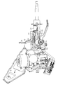
도 1은 본 발명의 일 실시예에 따른 고정장치를 구비하는 차량용 스티어링 컬럼이 도시된 구성도이다.
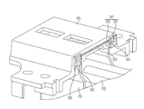
도 2는 본 발명의 일 실시에에 따른 차량의 스티어링 컬럼용 고정장치가 도시된 분해 사시도이다.
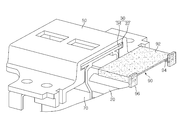
도 3은 본 발명의 일 실시예에 따른 차량의 스티어링 컬럼용 고정장치가 도시된 사시도이다.
도 4는 본 발명의 일 실시에에 따른 차량의 스티어링 컬럼용 고정장치가 도시된 사용 상태도이다.FIG. 1 is a configuration diagram showing a steering column for a vehicle having a fixing device according to an embodiment of the present invention.
2 is an exploded perspective view showing a fixing device for a steering column of a vehicle according to an embodiment of the present invention.
3 is a perspective view showing a fixing device for a steering column of a vehicle according to an embodiment of the present invention.
4 is a use state diagram showing a fixing device for a steering column of a vehicle according to an embodiment of the present invention.
이하, 첨부된 도면들을 참조하여 본 발명에 따른 차량의 스티어링 컬럼용 고정장치의 일 실시예를 설명한다.Hereinafter, an embodiment of a fixing device for a steering column of a vehicle according to the present invention will be described with reference to the accompanying drawings.
이러한 과정에서 도면에 도시된 선들의 두께나 구성요소의 크기 등은 설명의 명료성과 편의상 과장되게 도시되어 있을 수 있다.In this process, the thicknesses of the lines and the sizes of the components shown in the drawings may be exaggerated for clarity and convenience of explanation.
또한, 후술되는 용어들은 본 발명에서의 기능을 고려하여 정의된 용어들로써, 이는 사용자, 운용자의 의도 또는 관례에 따라 달라질 수 있다.In addition, the terms described below are terms defined in consideration of the functions of the present invention, which may vary depending on the intention or custom of the user, the operator.
그러므로 이러한 용어들에 대한 정의는 본 명세서 전반에 걸친 내용을 토대로 내려져야 할 것이다.
Therefore, definitions of these terms should be made based on the contents throughout this specification.
도 1은 본 발명의 일 실시예에 따른 고정장치를 구비하는 차량용 스티어링 컬럼이 도시된 구성도이고, 도 2는 본 발명의 일 실시에에 따른 차량의 스티어링 컬럼용 고정장치가 도시된 분해 사시도이고, 도 3은 본 발명의 일 실시예에 따른 차량의 스티어링 컬럼용 고정장치가 도시된 사시도이고, 도 4는 본 발명의 일 실시에에 따른 차량의 스티어링 컬럼용 고정장치가 도시된 사용 상태도이다.FIG. 1 is an exploded perspective view of a steering column fixing apparatus for a vehicle according to an embodiment of the present invention. FIG. 2 is a perspective view of the steering column fixing apparatus for a vehicle according to an embodiment of the present invention. FIG. 3 is a perspective view showing a fixing device for a steering column of a vehicle according to an embodiment of the present invention, and FIG. 4 is a state diagram showing a fixing device for a steering column of a vehicle according to an embodiment of the present invention.
도 1 내지 도 4를 참조하면, 본 발명의 일 실시예에 따른 차량의 스티어링 컬럼용 고정장치는, 차체(10)에 고정되는 마운팅 브래킷(50)과, 스티어링 컬럼(20)을 상하 방향으로 유동 가능하게 지지하는 틸트 브래킷(70)과, 틸트 브래킷(70)을 마운팅 브래킷(50)에 전후 방향으로 슬라이딩 가능하게 연결하는 지지부(30)를 포함한다.1 to 4, a fixing device for a steering column of a vehicle according to an embodiment of the present invention includes a
스티어링 컬럼(20)은 틸트 브래킷(70)에 의해 상하 방향으로 회전 가능하게 지지되므로 운전자가 스티어링 휠의 위치를 운전자의 취향에 맞게 조절할 수 있다.Since the
틸트 브래킷(70)은 고정부에 의해 전후 방향으로 슬라이딩 가능하게 지지되므로 차량 충돌 시에 틸트 브래킷(70)과 스티어링 컬럼(20)이 전후 방향으로 유동되면서 충격을 흡수할 수 있어 차량의 충돌 성능이 향상된다.Since the
본 실시예의 마운팅 브래킷(50)은 체결부재(58)에 의해 차체(10)에 고정되고, 고정부에 의해 틸트 브래킷(70)이 전후 방향으로 슬라이딩 가능하게 지지된다.The
따라서 차량 충돌 시에 스티어링 컬럼(20)이 마운팅 브래킷(50)으로부터 이탈되지 않고, 스티어링 컬럼(20)이 고정부에 의해 전후 방향으로 슬라이딩되면서 충격을 흡수하므로 스티어링 컬럼(20)이 하측 방향으로 떨어지거나 회전되는 것을 방지할 수 있게 된다.Therefore, at the time of a vehicle collision, the
지지부(30)는, 마운팅 브래킷(50)에 형성되고, 전후 방향으로 길게 형성되는 슬라이딩홈부(32)와, 슬라이딩홈부(32)에 유동 가능하게 삽입되도록 틸트 브래킷(70)에 형성되는 슬라이딩돌기(34)를 포함한다.The
슬라이딩홈부(32)는 마운팅 브래킷(50)의 저면에 한 쌍의 슬라이딩홈부(32)가 간격을 유지하도록 형성되고, 한 쌍의 슬라이딩홈부(32)는 평행을 이루며 전후 방향으로 길게 형성된다.The sliding
슬라이딩돌기(34)는 슬라이딩홈부(32)를 따라 삽입될 수 있도록 틸트 브래킷(70)의 상단에 한 쌍의 슬라이딩돌기(34)가 형성된다.A pair of sliding
따라서 틸트 브래킷(70)과 마운팅 브래킷(50)을 결합할 때에는 슬라이딩홈부(32)의 일측 단부로부터 슬라이딩돌기(34)를 삽입하여 틸트 브래킷(70)과 마운팅 브래킷(50)의 결합을 행할 수 있게 된다.When the
또한, 지지부(30)는 슬라이딩홈부(32)와 슬라이딩돌기(34) 사이에 개재되는 가이드부시(90)를 더 포함한다.The
가이드부시(90)는 슬라이딩홈부(32)와 슬라이딩돌기(34) 사이에 개재되어 슬라이딩돌기(34)가 슬라이딩홈부(32)를 따라 쉽게 유동되는 것을 방지하므로 차량이 충돌이 발생되지 않는 상태에서 틸트 브래킷(70)이 마운팅 브래킷(50)으로부터 유동되는 것을 방지하게 된다.The
가이드부시(90)는, 마운팅 브래킷(50)의 저면에 밀착되는 본체(92)와, 본체(92)의 양측 단부로부터 굴곡되어 슬라이딩홈부(32)와 슬라이딩돌기(34) 사이에 개재되는 굴곡부(94)와, 굴곡부(94)의 단부에 형성되고, 슬라이딩돌기(34)가 슬라이딩홈부(32)를 따라 이동될 때에 본체(92)가 유동되는 것을 방지하는 스토퍼(96)를 포함한다.The
본체(92)는 마운팅 브래킷(50)의 저면에 밀착되는 패널 모양으로 형성되고, 굴곡부(94)는 본체(92)의 양단부로부터 하측 방향으로 'ㄷ'모양으로 굴곡되어 슬라이딩돌기(34)의 양측 단부를 감싸도록 형성된다.The
스토퍼(96)는 굴곡부(94)의 일측 단부에 굴곡부(94)의 두께와 비교하여 더 큰 패널 모양으로 형성되어 굴곡부(94)의 일측 단부를 폐쇄하도록 설치된다.The
따라서 본체(92) 및 굴곡부(94)를 슬라이딩홈부(32)와 슬라이딩돌기(34) 사이에 개재시킬 때에 본체(92) 및 굴곡부(94)가 슬라이딩홈부(32)와 슬라이딩돌기(34) 사이에 완전히 삽입되면 스토퍼(96)가 슬라이딩홈부(32) 및 슬라이딩돌기(34)의 단부에 밀착되면서 본체(92) 및 굴곡부(94)의 삽입이 더 이상 이루어지지 않도록 한다.When the
스토퍼(96)는 본체(92) 및 굴곡부(94)가 삽입되는 방향과 직교되는 패널 모양으로 형성되어 굴곡부(94)의 일측 단부에 설치된다.The
따라서 본체(92) 및 굴곡부(94)를 슬라이딩홈부(32)와 슬라이딩돌기(34) 사이로 삽입할 때에 작업자가 스토퍼(96)를 가압하여 본체(92) 및 굴곡부(94)를 슬라이딩홈부(32)와 슬라이딩돌기(34) 사이의 간격으로 용이하게 삽입할 수 있게 된다.Therefore, when inserting the
마운팅 브래킷(50)은 알루미늄재질을 포함하여 이루어지므로 마운팅 브래킷(50)의 강도를 향상시킬 수 있어 차량 충돌 시에 마운팅 브래킷(50)이 파손되어 스티어링 컬럼(20)이 하측 방향으로 떨어지거나 회전되는 것을 방지할 수 있게 된다.Since the
또한, 마운팅 브래킷(50)은 체결부재(58)에 의해 차체(10)에 결합되고, 지지부(30)에 의해 스티어링 컬럼(20)이 마운팅 브래킷(50)에 전후 방향으로 슬라이딩 가능하게 지지되므로 차량 충돌 시에 스티어링 컬럼(20)이 마운팅 브래킷(50)으로부터 분리되도록 하는 별도의 캡슐이 요구되지 않는다.Since the
미설명 부호 60은 마운팅 플레이트(50)에 설치되는 컬링 플레이트(60)이고, 미설명 부호 78은 틸트 브래킷(70)에 설치되고, 컬링 플레이트(60)를 가압하는 윙부재(78)이다.
상기와 같이 구성된 본 발명의 일 실시예에 따른 차량의 스티어링 컬럼용 고정장치의 작동을 살펴보면 다음과 같다.Operation of the steering column fixing apparatus for a vehicle according to an embodiment of the present invention will now be described.
스티어링 컬럼(20)을 차체(10)에 설치할 때에는 마운팅 브래킷(50)을 체결부재(58)에 의해 차체(10)에 조립하고, 스티어링 컬럼(20)과 틸트 브래킷(70)을 조립한 후에 슬라이딩돌기(34)를 슬라이딩홈부(32)에 삽입하여 마운팅 브래킷(50)과 틸트 브래킷(70)의 조립을 완료한다.When mounting the
이후에, 작업자는 슬라이딩홈부(32)와 슬라이딩돌기(34) 사이의 간격으로 가이드부시(90)를 삽입하여 틸트 브래킷(70)이 유동되는 것을 방지하게 된다.Thereafter, the operator inserts the
차량 충돌이 발생되면 스티어링 컬럼(20)이 전후 방향으로 유동되면서 충격을 상쇄시키게 되는데, 이때, 슬라이딩돌기(34)는 슬라이딩홈부(32)를 따라 전후 방향으로 슬라이딩된다.When a vehicle collision occurs, the
따라서 스티어링 컬럼(20)은 전후 방향으로 슬라이딩되면서 충격을 상쇄시키고, 스티어링 컬럼(20)이 하측 방향으로 떨어지는 것을 방지하게 된다.Therefore, the
또한, 차량 충돌에 의해 스티어링 컬럼(20)이 전후 방향으로 슬라이딩되어도 슬라이딩돌기(34)는 슬라이딩홈부(32) 내측에 위치되므로 스티어링 컬럼(20)이 회전되는 것을 방지할 수 있게 된다.Further, even if the
이로써, 차량 충돌 후에 스티어링 컬럼(20)의 처짐 및 회전을 방지할 수 있는 차량의 스티어링 컬럼용 고정장치를 제공할 수 있게 된다.
This makes it possible to provide a fixing device for a steering column of a vehicle that can prevent deflection and rotation of the
본 발명은 도면에 도시되는 일 실시예를 참고로 하여 설명되었으나, 이는 예시적인 것에 불과하며, 당해 기술이 속하는 분야에서 통상의 지식을 가진 자라면 이로부터 다양한 변형 및 균등한 타 실시예가 가능하다는 점을 이해할 것이다.While the present invention has been particularly shown and described with reference to exemplary embodiments thereof, it is to be understood that the invention is not limited to the disclosed embodiments, but, on the contrary, is intended to cover various modifications and equivalent arrangements included within the spirit and scope of the appended claims. .
또한, 차량의 스티어링 컬럼용 고정장치를 예로 들어 설명하였으나, 이는 예시적인 것에 불과하며, 차량의 스티어링 컬럼용 고정장치가 아닌 다른 제품에도 본 발명의 고정장치가 사용될 수 있다.Also, although a fixing device for a steering column of a vehicle has been described as an example, this is merely an example, and the fixing device of the present invention can be used for products other than the fixing device for a steering column of a vehicle.
따라서 본 발명의 진정한 기술적 보호범위는 아래의 특허청구범위에 의해서 정하여져야 할 것이다.
Accordingly, the true scope of the present invention should be determined by the following claims.
10 : 차체 20 : 스티어링 컬럼
30 : 지지부 32 : 슬라이딩홈부
34 : 슬라이딩돌기 50 : 마운팅 브래킷
58 : 체결부재 60 : 컬링 플레이트
70 : 틸트 브래킷 78 : 윙부재
90 : 가이드부시 92 : 본체
94 : 굴곡부 96 : 스토퍼10: Body 20: Steering column
30: Support part 32: Sliding groove part
34: Sliding projection 50: Mounting bracket
58: fastening member 60: curling plate
70: tilt bracket 78: wing member
90: Guide bush 92: Body
94: Bend 96: Stopper
Claims (5)
스티어링 컬럼을 상하 방향으로 유동 가능하게 지지하는 틸트 브래킷;
상기 틸트 브래킷을 상기 마운팅 브래킷에 전후 방향으로 슬라이딩 가능하게 연결하는 지지부를 포함하는 것을 특징으로 하는 차량의 스티어링 컬럼용 고정장치.
A mounting bracket fixed to the vehicle body;
A tilt bracket for supporting the steering column so as to be vertically movable;
And a support for slidably connecting the tilt bracket to the mounting bracket in the forward and backward directions.
상기 마운팅 브래킷에 형성되고, 전후 방향으로 길게 형성되는 슬라이딩홈부; 및
상기 슬라이딩홈부에 유동 가능하게 삽입되도록 상기 틸트 브래킷에 형성되는 슬라이딩돌기를 포함하는 것을 특징으로 하는 차량의 스티어링 컬럼용 고정장치.
The apparatus according to claim 1,
A sliding groove portion formed in the mounting bracket and elongated in the front-rear direction; And
And a sliding protrusion formed on the tilt bracket to be inserted into the sliding groove part so as to be freely movable.
상기 지지부는 상기 슬라이딩홈부와 상기 슬라이딩돌기 사이에 개재되는 가이드부시를 더 포함하는 것을 특징으로 하는 차량의 스티어링 컬럼용 고정장치.3. The method of claim 2,
Wherein the support portion further comprises a guide bush interposed between the sliding groove and the sliding protrusion.
상기 마운팅 브래킷의 저면에 밀착되는 본체;
상기 본체의 양측 단부로부터 굴곡되어 상기 슬라이딩홈부와 상기 슬라이딩돌기 사이에 개재되는 굴곡부; 및
상기 굴곡부의 단부에 형성되고, 상기 슬라이딩돌기가 상기 슬라이딩홈부를 따라 이동될 때에 상기 본체가 유동되는 것을 방지하는 스토퍼를 포함하는 것을 특징으로 하는 차량의 스티어링 컬럼용 고정장치.
[5] The apparatus of claim 3,
A main body which is brought into close contact with a bottom surface of the mounting bracket;
A bending portion bent from both side ends of the body and interposed between the sliding groove and the sliding protrusion; And
And a stopper formed at an end of the bent portion to prevent the body from flowing when the sliding protrusion is moved along the sliding groove portion.
상기 마운팅 브래킷은 알루미늄재질을 포함하여 이루어지는 것을 특징으로 하는 차량의 스티어링 컬럼용 고정장치.
5. The method according to any one of claims 1 to 4,
Wherein the mounting bracket includes an aluminum material.
Priority Applications (2)
| Application Number | Priority Date | Filing Date | Title |
|---|---|---|---|
| KR1020120151376A KR20140090717A (en) | 2012-12-21 | 2012-12-21 | Fixing apparatus for steering column in vehicles |
| CN201310285397.9A CN103879437B (en) | 2012-12-21 | 2013-07-09 | Fixing device for steering column for vehicle |
Applications Claiming Priority (1)
| Application Number | Priority Date | Filing Date | Title |
|---|---|---|---|
| KR1020120151376A KR20140090717A (en) | 2012-12-21 | 2012-12-21 | Fixing apparatus for steering column in vehicles |
Publications (1)
| Publication Number | Publication Date |
|---|---|
| KR20140090717A true KR20140090717A (en) | 2014-07-18 |
Family
ID=50948651
Family Applications (1)
| Application Number | Title | Priority Date | Filing Date |
|---|---|---|---|
| KR1020120151376A KR20140090717A (en) | 2012-12-21 | 2012-12-21 | Fixing apparatus for steering column in vehicles |
Country Status (2)
| Country | Link |
|---|---|
| KR (1) | KR20140090717A (en) |
| CN (1) | CN103879437B (en) |
Family Cites Families (5)
| Publication number | Priority date | Publication date | Assignee | Title |
|---|---|---|---|---|
| JP3388158B2 (en) * | 1997-10-29 | 2003-03-17 | 日野自動車株式会社 | Steering support structure |
| FR2805512B1 (en) * | 2000-02-24 | 2002-05-03 | Nacam | DEVICE FOR LINEAR GUIDANCE OF A STEERING COLUMN |
| KR101065895B1 (en) * | 2007-03-30 | 2011-09-19 | 주식회사 만도 | Steering Column for Motor Vehicle Having Collision Energy Absorbing Apparatus |
| KR101204541B1 (en) * | 2007-11-12 | 2012-11-23 | 주식회사 만도 | A telescopic device and tilt device of the steering column for a vehicle |
| KR20110109297A (en) * | 2010-03-31 | 2011-10-06 | 남양공업주식회사 | System for suction impact of steering column |
-
2012
- 2012-12-21 KR KR1020120151376A patent/KR20140090717A/en not_active Application Discontinuation
-
2013
- 2013-07-09 CN CN201310285397.9A patent/CN103879437B/en active Active
Also Published As
| Publication number | Publication date |
|---|---|
| CN103879437A (en) | 2014-06-25 |
| CN103879437B (en) | 2017-07-21 |
Similar Documents
| Publication | Publication Date | Title |
|---|---|---|
| EP2574491B1 (en) | Support device of an adjustable vehicular display integrated in the dashboard of a vehicle, in particular an industrial or commercial vehicle | |
| US8985542B2 (en) | Sensor assembly for a movable seat | |
| US10486731B2 (en) | Steering apparatus | |
| US9457700B2 (en) | Head rest | |
| CN104742975A (en) | Cowl cross member assembly for vehicle | |
| KR101576377B1 (en) | Reclining module for head rest | |
| JP6505554B2 (en) | Slide position detection device for vehicle seat | |
| US20110115275A1 (en) | Swivelable Arm Rest For Use In A Vehicle | |
| US9415714B2 (en) | Lumber support apparatus for vehicle | |
| KR100636402B1 (en) | Lumbar support device for automobile | |
| KR101795442B1 (en) | Steering column assembly for a car | |
| WO2015045492A1 (en) | Knee protector structure for vehicle | |
| EP2921341B1 (en) | Adjustable side support | |
| KR20140090717A (en) | Fixing apparatus for steering column in vehicles | |
| KR101615224B1 (en) | Steering column assembly for car | |
| JP2013100022A (en) | Instrument panel structure | |
| KR101620312B1 (en) | The head rest for automobile to be attached the head supporter | |
| JP2011057004A (en) | Steering adjusting clearance shielding structure | |
| KR20130052644A (en) | Adjusting mechanism, in particular in the interior fittings area of a motor vehicle | |
| CN111328311B (en) | Headrest control device | |
| KR20160013405A (en) | Apparatus for adjusting height of armrest | |
| CN111163994B (en) | Adjustable steering column assembly | |
| JP6772750B2 (en) | Vehicle steering device | |
| EP2554430B1 (en) | Seat back tilting mechnism of a vehicle seat, in particular for industrial and commercial vehicles | |
| CN104249753A (en) | Steering system attachment |
Legal Events
| Date | Code | Title | Description |
|---|---|---|---|
| A201 | Request for examination | ||
| E902 | Notification of reason for refusal | ||
| E601 | Decision to refuse application |