KR20140089216A - Unit for supplying chemical - Google Patents
Unit for supplying chemical Download PDFInfo
- Publication number
- KR20140089216A KR20140089216A KR1020130001194A KR20130001194A KR20140089216A KR 20140089216 A KR20140089216 A KR 20140089216A KR 1020130001194 A KR1020130001194 A KR 1020130001194A KR 20130001194 A KR20130001194 A KR 20130001194A KR 20140089216 A KR20140089216 A KR 20140089216A
- Authority
- KR
- South Korea
- Prior art keywords
- flow rate
- chemical liquid
- chemical solution
- supply
- chemical
- Prior art date
Links
Images


Classifications
-
- H—ELECTRICITY
- H01—ELECTRIC ELEMENTS
- H01L—SEMICONDUCTOR DEVICES NOT COVERED BY CLASS H10
- H01L21/00—Processes or apparatus adapted for the manufacture or treatment of semiconductor or solid state devices or of parts thereof
- H01L21/67—Apparatus specially adapted for handling semiconductor or electric solid state devices during manufacture or treatment thereof; Apparatus specially adapted for handling wafers during manufacture or treatment of semiconductor or electric solid state devices or components ; Apparatus not specifically provided for elsewhere
- H01L21/67005—Apparatus not specifically provided for elsewhere
- H01L21/67011—Apparatus for manufacture or treatment
- H01L21/67017—Apparatus for fluid treatment
- H01L21/67028—Apparatus for fluid treatment for cleaning followed by drying, rinsing, stripping, blasting or the like
- H01L21/6704—Apparatus for fluid treatment for cleaning followed by drying, rinsing, stripping, blasting or the like for wet cleaning or washing
-
- H—ELECTRICITY
- H01—ELECTRIC ELEMENTS
- H01L—SEMICONDUCTOR DEVICES NOT COVERED BY CLASS H10
- H01L21/00—Processes or apparatus adapted for the manufacture or treatment of semiconductor or solid state devices or of parts thereof
- H01L21/67—Apparatus specially adapted for handling semiconductor or electric solid state devices during manufacture or treatment thereof; Apparatus specially adapted for handling wafers during manufacture or treatment of semiconductor or electric solid state devices or components ; Apparatus not specifically provided for elsewhere
- H01L21/67005—Apparatus not specifically provided for elsewhere
- H01L21/67242—Apparatus for monitoring, sorting or marking
- H01L21/67253—Process monitoring, e.g. flow or thickness monitoring
Abstract
Description
본 발명은 약액을 이용하여 기판을 처리하는 장치 및 방법에 관한 것이다.The present invention relates to an apparatus and a method for processing a substrate using a chemical liquid.
반도체소자 또는 액정 디스플레이를 제조하기 위해서, 기판에 포토리소그라피, 식각, 애싱, 이온주입, 그리고 박막 증착등의 다양한 공정들이 수행된다. 이러한 공정에는 오염물 및 파티클이 생성되며, 이를 제거하기 위해 각각의 공정 진행 전 또는 후 단계에는 기판을 세정하는 세정공정이 실시된다. In order to manufacture semiconductor devices or liquid crystal displays, various processes such as photolithography, etching, ashing, ion implantation, and thin film deposition are performed on the substrate. In such a process, contaminants and particles are generated. In order to remove the contaminants and particles, a cleaning process is performed to clean the substrate before or after each process step.
세정공정은 기설정된 유량 및 온도로 제어된 약액을 기판으로 공급하는 공정을 포함한다. 일반적으로 세정공정에는 약액의 토출유량을 제어하기 위해 고정량 공급방식 또는 피드백 공급방식이 사용된다. The cleaning process includes a step of supplying a chemical solution controlled to a predetermined flow rate and temperature to the substrate. Generally, in the cleaning process, a fixed amount supply method or a feedback supply method is used to control the discharge flow rate of the chemical liquid.
고정량 공급방식은 작업자가 매뉴얼로 밸브의 개구율을 고정하여 약액의 공급 유량을 조정하는 방식이다. 도1은 고정량 공급방식으로 약액의 유량을 조정 시 약액의 유량 변동을 보여주는 표이다. 도1을 참조하면, 고정량 공급방식은 공정 초기에 요구되는 토출 유량에 대해 빠른 반응속도를 가진다. 그러나 요구되는 토출 유량이 변경될 시 작업자에 의해 변경되어야 한다. 또한 고정량 공급방식을 사용 시 복수 개의 장치들에 동일한 공급 유량을 제공하도록 조정하는 것은 어렵다. 또한 고온의 약액에 대해 고정량 공급방식을 사용 시 밸브는 열변형으로 인해 약액의 실제 공급 유량이 요구 유량과 상이할 수 있다.The fixed amount supply method is a method in which the operator manually adjusts the flow rate of the chemical liquid by fixing the opening ratio of the valve. FIG. 1 is a table showing fluctuation of the flow rate of the chemical liquid when the flow rate of the chemical liquid is adjusted by the fixed amount supply system. Referring to FIG. 1, the fixed quantity supply system has a rapid reaction rate with respect to the discharge flow rate required at the initial stage of the process. However, it must be changed by the operator when the required discharge flow rate is changed. It is also difficult to adjust to provide the same feed rate to a plurality of devices when using a fixed quantity feed scheme. Also, when a fixed amount supply method is used for a high temperature chemical solution, the actual supply flow rate of the chemical liquid may be different from the required flow rate due to thermal deformation of the valve.
이에 반해 피드백 공급방식은 약액공급라인에 공급되는 약액의 유량을 측정하고, 측정된 값을 기초로 하여 약액의 공급 유량을 실시간으로 조정하는 방식이다. 도2는 피드백 공급방식으로 약액의 유량을 조정 시 약액의 유량 변동을 보여주는 표이다. 도2를 참조하면, 피드백 공급방식은 장치의 주변 환경에 대해 빠르게 대응이 가능하다. 그러나 동작신호에 의한 초기 반응속도가 고정량 공급방식에 비해 느리고, 약액의 초기 공급 유량이 요구 유량을 오버할 수 있다.On the other hand, the feedback supply method measures the flow rate of the chemical liquid supplied to the chemical liquid supply line, and adjusts the supply flow rate of the chemical liquid based on the measured value in real time. Fig. 2 is a table showing fluctuation of the flow rate of the chemical liquid when the flow rate of the chemical liquid is adjusted by the feedback supply system. Referring to FIG. 2, the feedback supply method can quickly respond to the environment of the apparatus. However, the initial reaction rate due to the operation signal is slower than the fixed amount supply method, and the initial supply flow rate of the chemical solution may exceed the required flow rate.
본 발명은 고정량 공급방식과 피드백 공급방식의 단점을 해소할 수 있는 장치를 제공하고자 한다.The present invention is intended to provide a device capable of eliminating the disadvantages of the fixed quantity supply method and the feedback supply method.
본 발명의 실시예에는 약액을 이용하여 기판을 처리하는 장치 및 방법을 제공한다. 약액공급유닛은 약액이 제공되는 액 공급원, 상기 액 공급원 및 노즐에 연결되는 약액공급라인, 그리고 상기 약액공급라인에 설치되고, 약액의 유량이 일정하게 공급되도록 약액의 유량을 조절하는 유량조절부를 포함하되, 상기 유량조절부는 약액 토출 초기에 약액의 유량을 고정량 공급방식으로 조절하고, 이후에 약액의 유량을 피드백 공급방식으로 조절한다.An embodiment of the present invention provides an apparatus and a method for processing a substrate using a chemical liquid. The chemical liquid supply unit includes a liquid supply source to which the chemical liquid is supplied, a chemical liquid supply line connected to the liquid supply source and the nozzle, and a flow rate adjusting unit installed in the chemical liquid supply line and controlling the flow rate of the chemical liquid so that the chemical liquid flow rate is uniformly supplied The flow rate regulator adjusts the flow rate of the chemical liquid at the initial stage of the chemical liquid discharge to the fixed amount supply mode, and then adjusts the flow rate of the chemical liquid to the feedback supply mode.
상기 유량조절부는 상기 약액공급라인에 제공된 약액의 유량을 측정하는 유량측정부재, 상기 약액공급라인에 제공된 약액의 유량을 조절하는 유량조절부재, 그리고 상기 유량측정부재 및 상기 유량조절부재에 연결되고, 상기 유량조절부재를 상기 고정량 공급방식 또는 상기 피드백 공급방식으로 제어하는 제어기를 포함하되, 상기 제어기는 상기 고정량 공급방식으로 상기 유량조절부재를 제어 시 상기 유량조절부재의 개구율이 고정시키고, 상기 피드백 공급방식으로 상기 유량조절부재를 제어 시 상기 유량측정부재로부터 측정된 정보를 기초로 하여 상기 유량조절부재의 개구율을 조절할 수 있다. 상기 제어기는 기설정된 시간동안 상기 유량조절부재를 상기 고정량 공급방식으로 제어하고, 그 이후에 상기 유량조절부재를 상기 피드백 공급방식으로 제어할 수 있다. 상기 기설정된 시간은 약액의 공급유량이 공정에서 요구되는 유량에 도달되는 시간과 동일하거나 이보다 길게 제공될 수 있다.Wherein the flow rate regulator includes a flow rate measuring member for measuring a flow rate of the chemical solution supplied to the chemical solution supply line, a flow rate adjusting member for adjusting a flow rate of the chemical solution supplied to the chemical solution supply line, And a controller for controlling the flow rate adjusting member to the fixed amount supply mode or the feedback supply mode, wherein the controller fixes the opening ratio of the flow rate adjusting member when the flow rate adjusting member is controlled by the fixed amount supply mode, The opening ratio of the flow rate adjusting member can be adjusted based on the information measured from the flow rate measuring member when the flow rate adjusting member is controlled by the feedback supply method. The controller can control the flow regulating member in the fixed amount supply mode for a predetermined time and thereafter control the flow regulating member in the feedback regulating manner. The predetermined time may be equal to or longer than the time at which the supply flow rate of the chemical liquid reaches the flow rate required in the process.
기판처리장치는 기판을 지지하는 스핀헤드, 상기 스핀헤드에 지지된 기판 상으로 약액을 분사하는 노즐을 가지는 분사유닛, 그리고 상기 분사유닛에 약액을 공급하는 약액공급유닛을 포함하되, 상기 약액공급유닛은 약액이 제공되는 액 공급원, 상기 액 저장원 및 상기 노즐에 연결되는 약액공급라인, 그리고 상기 약액공급라인에 설치되고, 약액의 유량이 일정하게 공급되도록 약액의 공급 유량을 조절하는 유량조절부를 포함하되, 상기 유량조절부는 약액 토출 초기에 약액의 유량을 고정량 공급방식으로 조절하고, 이후에 약액의 유량을 피드백 공급방식으로 조절한다.The substrate processing apparatus includes a spin head for supporting a substrate, a spray unit having a nozzle for spraying a chemical solution onto a substrate supported by the spin head, and a chemical solution supply unit for supplying a chemical solution to the spray unit, A chemical liquid supply line connected to the liquid storage source and the nozzle, and a flow rate adjusting unit installed in the chemical liquid supply line and controlling a supply flow rate of the chemical liquid so that the chemical liquid flow rate is uniformly supplied The flow rate regulator adjusts the flow rate of the chemical liquid at the initial stage of the chemical liquid discharge to the fixed amount supply mode, and then adjusts the flow rate of the chemical liquid to the feedback supply mode.
상기 유량조절부는 상기 약액공급라인에 제공된 약액의 유량을 측정하는 유량측정부재, 상기 약액공급라인에 제공된 약액의 유량을 조절하는 유량조절부재, 그리고 상기 유량측정부재 및 상기 유량조절부재에 연결되고, 상기 유량조절부재를 상기 고정량 공급방식 또는 상기 피드백 공급방식으로 제어하는 제어기를 포함하되, 상기 제어기는 상기 고정량 공급방식으로 상기 유량조절부재를 제어 시 상기 유량조절부재의 개구율이 고정시키고, 상기 피드백 공급방식으로 상기 유량조절부재를 제어 시 상기 유량측정부재로부터 측정된 정보를 기초로 하여 상기 유량조절부재의 개구율을 조절할 수 있다.Wherein the flow rate regulator includes a flow rate measuring member for measuring a flow rate of the chemical solution supplied to the chemical solution supply line, a flow rate adjusting member for adjusting a flow rate of the chemical solution supplied to the chemical solution supply line, And a controller for controlling the flow rate adjusting member to the fixed amount supply mode or the feedback supply mode, wherein the controller fixes the opening ratio of the flow rate adjusting member when the flow rate adjusting member is controlled by the fixed amount supply mode, The opening ratio of the flow rate adjusting member can be adjusted based on the information measured from the flow rate measuring member when the flow rate adjusting member is controlled by the feedback supply method.
기판 상에 약액을 공급하여 상기 기판을 처리하는 방법은 약액공급라인에 설치된 유량조절부재를 고정량 공급방식으로 제어하여 약액의 공급 유량이 일정하도록 제어하는 고정량 공급단계 및 상기 고정량 공급단계 이후에, 상기 유량조절부재를 피드백 공급방식으로 제어하여 약액의 유량이 일정하도록 제어하는 피드백 공급단계를 포함한다.A method of supplying a chemical solution on a substrate and treating the substrate includes a fixed amount supply step of controlling a flow amount adjusting member provided in a chemical solution supply line to a fixed amount supply mode so that the supply flow rate of the chemical solution is constant, And a feedback supply step of controlling the flow rate adjusting member to a feedback supply mode to control the flow rate of the chemical liquid to be constant.
상기 고정량 공급단계는 기설정된 시간 이후에 상기 피드백 공급단계로 전환하되, 상기 기설정 시간은 약액의 공급유량이 공정에서 요구되는 유량에 도달되는 시간과 동일하거나, 이보다 길게 제공될 수 있다.The fixed amount supply step is switched to the feedback supply step after a predetermined time, and the predetermined time may be equal to or longer than the time when the supply flow rate of the chemical liquid reaches the flow rate required in the process.
본 발명의 실시예에 의하면, 공정 초기에 고정량 공급방식으로 액을 공급하고, 이후에 피드백 공급방식으로 액을 공급하므로, 공정 초기에 공급되는 약액의 유량의 반응속도를 높히고, 이후에 공급되는 약액의 유량 변동에 대해 대처할 수 있다.According to the embodiment of the present invention, since the liquid is supplied in the fixed amount supply method at the beginning of the process and then the liquid is supplied by the feedback supply method, the reaction rate of the flow rate of the chemical liquid supplied at the beginning of the process is increased, It is possible to cope with the fluctuation of the flow rate of the chemical liquid.
도1은 고정량 공급방식으로 약액의 유량을 조정 시 약액의 유량 변동을 보여주는 표이다.
도2는 피드백 공급방식으로 약액의 유량을 조정 시 약액의 유량 변동을 보여주는 표이다.
도3은 본 발명의 실시예에 따른 기판처리설비를 보여주는 평면도이다.
도4는 도3의 기판처리유닛을 보여주는 단면도이다.
도5는 도3의 약액공급유닛을 개략적으로 보여주는 블럭도이다.
도6은 도5의 약액공급유닛에 의해 공급되는 약액의 유량을 보여주는 표이다.FIG. 1 is a table showing fluctuation of the flow rate of the chemical liquid when the flow rate of the chemical liquid is adjusted by the fixed amount supply system.
Fig. 2 is a table showing fluctuation of the flow rate of the chemical liquid when the flow rate of the chemical liquid is adjusted by the feedback supply system.
3 is a plan view showing a substrate processing apparatus according to an embodiment of the present invention.
4 is a cross-sectional view showing the substrate processing unit of Fig.
5 is a block diagram schematically showing the chemical liquid supply unit of FIG.
FIG. 6 is a table showing the flow rate of the chemical liquid supplied by the chemical liquid supply unit of FIG. 5;
본 발명의 실시예는 여러 가지 형태로 변형될 수 있으며, 본 발명의 범위가 아래에서 서술하는 실시예로 인해 한정되어지는 것으로 해석되어서는 안된다. 본 실시예는 당업계에서 평균적인 지식을 가진 자에게 본 발명을 보다 완전하게 설명하기 위해서 제공되는 것이다. 따라서 도면에서의 구성 요소의 형상 등은 보다 명확한 설명을 강조하기 위해서 과장된 것이다.The embodiments of the present invention can be modified into various forms and the scope of the present invention should not be interpreted as being limited by the embodiments described below. The present embodiments are provided to enable those skilled in the art to more fully understand the present invention. Accordingly, the shapes of the components and the like in the drawings are exaggerated in order to emphasize a clearer description.
본 실시예에는 세정액 및 건조액을 사용하여 기판을 세정 처리하는 공정을 예로 들어 설명한다. 그러나 본 실시예는 세정공정에 한정되지 않으며, 현상액 및 식각액 등 다양한 종류의 액에 적용 가능하다. .In this embodiment, a process of cleaning the substrate by using a cleaning liquid and a drying liquid will be described as an example. However, the present embodiment is not limited to the cleaning process, and can be applied to various kinds of liquids such as a developing solution and an etching solution. .
이하, 도3 내지 도6을 참조하여 본 발명의 일 예를 상세히 설명한다.Hereinafter, an example of the present invention will be described in detail with reference to FIG. 3 to FIG.
도3은 본 발명의 실시예에 따른 기판처리설비를 보여주는 평면도이다. 도3을 참조하면, 기판처리설비(1)는 인덱스모듈(10)과 공정처리모듈(20)을 가진다. 인덱스모듈(10)은 로드포트(120) 및 이송프레임(140)을 가진다. 로드포트(120), 이송프레임(140), 그리고 공정처리모듈(20)은 순차적으로 일렬로 배열된다. 이하, 로드포트(120), 이송프레임(140), 그리고 공정처리모듈(20)이 배열된 방향을 제1방향(12)이라 하고, 상부에서 바라볼 때, 제1방향(12)과 수직한 방향을 제2방향(14)이라 하며, 제1방향(12)과 제2방향(14)을 포함한 평면에 수직인 방향을 제3방향(16)이라 칭한다. 3 is a plan view showing a substrate processing apparatus according to an embodiment of the present invention. Referring to FIG. 3, the
로드포트(140)에는 기판(W)이 수납된 캐리어(130)가 안착된다. 로드포트(120)는 복수 개가 제공되며 이들은 제2방향(14)을 따라 일렬로 배치된다. 로드포트(120)의 개수는 공정처리모듈(20)의 공정효율 및 풋 프린트조건 등에 따라 증가하거나 감소할 수도 있다. 캐리어(130)에는 기판(W)들을 지면에 대해 수평하게 배치한 상태로 수납하기 위한 다수의 슬롯(미도시)이 형성된다. 캐리어(130)로는 전면개방일체형포드(Front Opening Unifed Pod;FOUP)가 사용될 수 있다. The carrier 130 in which the substrate W is accommodated is seated in the
공정처리모듈(20)은 버퍼유닛(220), 이송챔버(240), 그리고 공정챔버(260)를 가진다. 이송챔버(240)는 그 길이 방향이 제 1 방향(12)과 평행하게 배치된다. 이송챔버(240)의 양측에는 각각 기판처리부(300a)(260)들이 배치된다. 이송챔버(240)의 일측 및 타측에서 기판처리부(300a)(260)들은 이송챔버(240)를 기준으로 대칭되도록 제공된다. 이송챔버(240)의 일측에는 복수 개의 기판처리부(300a)(260)들이 제공된다. 공정챔버(260)들 중 일부는 이송챔버(240)의 길이 방향을 따라 배치된다. 또한, 공정챔버(260)들 중 일부는 서로 적층되게 배치된다. 즉, 이송챔버(240)의 일측에는 공정챔버(260)들이 A X B의 배열로 배치될 수 있다. 여기서 A는 제1방향(12)을 따라 일렬로 제공된 공정챔버(260)의 수이고, B는 제3방향(16)을 따라 일렬로 제공된 공정챔버(260)의 수이다. 이송챔버(240)의 일측에 공정챔버(260)가 4개 또는 6개 제공되는 경우, 공정챔버(260)들은 2 X 2 또는 3 X 2의 배열로 배치될 수 있다. 공정챔버(260)의 개수는 증가하거나 감소할 수도 있다. 상술한 바와 달리, 공정챔버(260)는 이송챔버(240)의 일측에만 제공될 수 있다. 또한, 공정챔버(260)는 이송챔버(240)의 일측 및 양측에 단층으로 제공될 수 있다.The
버퍼유닛(220)은 이송프레임(140)과 이송챔버(240) 사이에 배치된다. 버퍼 유닛(220)은 이송챔버(240)와 이송프레임(140) 간에 기판(W)이 반송되기 전에 기판(W)이 머무르는 공간을 제공한다. 버퍼유닛(220)의 내부에는 기판(W)이 놓이는 슬롯(미도시)이 제공된다. 슬롯(미도시)들은 서로 간에 제3방향(16)을 따라 이격되도록 복수 개가 제공된다. 버퍼유닛(220)은 이송프레임(140)과 마주보는 면 및 이송챔버(240)와 마주보는 면이 개방된다. The
이송프레임(140)은 로드포트(120)에 안착된 캐리어(130)와 버퍼유닛(220) 간에 기판(W)을 반송한다. 이송프레임(140)에는 인덱스레일(142)과 인덱스로봇(144)이 제공된다. 인덱스레일(142)은 그 길이 방향이 제2방향(14)과 나란하게 제공된다. 인덱스로봇(144)은 인덱스레일(142) 상에 설치되며, 인덱스레일(142)을 따라 제2방향(14)으로 직선 이동된다. 인덱스로봇(144)은 베이스(144a), 몸체(144b), 그리고 인덱스암(144c)을 가진다. 베이스(144a)는 인덱스레일(142)을 따라 이동 가능하도록 설치된다. 몸체(144b)는 베이스(144a)에 결합된다. 몸체(144b)는 베이스(144a) 상에서 제3방향(16)을 따라 이동 가능하도록 제공된다. 또한, 몸체(144b)는 베이스(144a) 상에서 회전 가능하도록 제공된다. 인덱스암(144c)은 몸체(144b)에 결합되고, 몸체(144b)에 대해 전진 및 후진 이동 가능하도록 제공된다. 인덱스암(144c)은 복수 개 제공되어 각각 개별 구동되도록 제공된다. 인덱스암(144c)들은 제3방향(16)을 따라 서로 이격된 상태로 적층되게 배치된다. 인덱스암(144c)들 중 일부는 공정처리모듈(20)에서 캐리어(130)로 기판(W)을 반송할 때 사용되고, 이의 다른 일부는 캐리어(130)에서 공정처리모듈(20)로 기판(W)을 반송할 때 사용될 수 있다. 이는 인덱스로봇(144)이 기판(W)을 반입 및 반출하는 과정에서 공정 처리 전의 기판(W)으로부터 발생된 파티클이 공정 처리 후의 기판(W)에 부착되는 것을 방지할 수 있다. The
이송챔버(240)는 버퍼유닛(220)과 공정챔버(260) 간에, 그리고 공정챔버(260)들 간에 기판(W)을 반송한다. 이송챔버(240)에는 가이드레일(242)과 메인로봇(244)이 제공된다. 가이드레일(242)은 그 길이 방향이 제1방향(12)과 나란하도록 배치된다. 메인로봇(244)은 가이드레일(242) 상에 설치되고, 가이드레일(242) 상에서 제1방향(12)을 따라 직선 이동된다. 메인로봇(244)은 베이스(244a), 몸체(244b), 그리고 메인암(244c)을 가진다. 베이스(244a)는 가이드레일(242)을 따라 이동 가능하도록 설치된다. 몸체(244b)는 베이스(244a)에 결합된다. 몸체(244b)는 베이스(244a) 상에서 제3방향(16)을 따라 이동 가능하도록 제공된다. 또한, 몸체(244b)는 베이스(244a) 상에서 회전 가능하도록 제공된다. 메인암(244c)은 몸체(244b)에 결합되고, 이는 몸체(244b)에 대해 전진 및 후진 이동 가능하도록 제공된다. 메인암(244c)은 복수 개 제공되어 각각 개별 구동되도록 제공된다. 메인암(244c)들은 제3방향(16)을 따라 서로 이격된 상태로 적층되게 배치된다. The
공정처리챔버(260)는 기판(W)에 대해 세정 공정을 수행하는 기판처리장치(300)가 제공된다. 기판처리장치(300)는 수행하는 세정 공정의 종류에 따라 상이한 구조를 가질 수 있다. 이와 달리 각각의 공정처리챔버(260) 내의 기판처리장치(300)는 동일한 구조를 가질 수 있다. 선택적으로 공정챔버(260)들은 복수 개의 그룹으로 구분되어, 동일한 그룹에 속하는 공정챔버(260) 내에 기판처리장치(300)들은 서로 동일하고, 서로 상이한 그룹에 속하는 공정챔버(260) 내에 기판처리장치(300)의 구조는 서로 상이하게 제공될 수 있다.The
기판처리장치(300)는 기판처리유닛(302) 및 약액공급유닛(304)을 포함한다. 기판처리유닛(302)은 기판(W)에 대해 세정공정을 수행하고, 약액공급유닛(304)은 기판처리유닛(302)으로 약액을 공급한다. 도4는 도3의 기판처리장치의 기판처리유닛을 보여주는 단면도이다. 도4를 참조하면, 기판처리유닛(302)은 하우징(320), 스핀헤드(340), 승강유닛(360), 그리고 분사유닛(380)를 포함한다. 하우징(320)은 상부가 개방된 통 형상을 가진다. 하우징(320)은 내부회수통(322) 및 외부회수통(328)을 가진다. 각각의 회수통(322,328)은 공정에 사용된 약액들 중 서로 상이한 약액을 회수한다. 내부회수통(322)은 스핀헤드(340)를 감싸는 환형의 링 형상으로 제공되고, 외부회수통(328)은 내부회수통(328)을 감싸는 환형의 링 형상으로 제공된다. 내부회수통(322)의 내측공간(322a) 및 내부회수통(322)과 외부회수통(328)의 사이공간(328a)은 각각 내부회수통(322) 및 외부회수통(328)으로 약액이 유입되는 유입구로서 기능한다. 일 예에 의하면, 각각의 유입구는 서로 상이한 높이에 위치될 수 있다. 각각의 회수통(322,328)의 저면 아래에는 회수라인(322b,328b)이 연결된다. 각각의 회수통(322,328)에 유입된 약액들은 회수라인(322b,328b)을 통해 외부의 약액재생시스템(미도시)으로 제공되어 재사용될 수 있다.The substrate processing apparatus 300 includes a
스핀헤드(340)는 공정 진행 중 기판(W)을 지지하고 기판(W)을 회전시킨다. 스핀헤드(340)는 몸체(342), 지지핀(344), 척핀(346), 그리고 지지축(348)을 가진다. 몸체(342)는 상부에서 바라볼 때 대체로 원형으로 제공되는 상부면을 가진다. 몸체(342)의 저면에는 구동부(349)에 의해 회전가능한 지지축(348)이 고정결합된다.The
지지핀(344)은 복수 개 제공된다. 지지핀(344)은 몸체(342)의 상부면의 가장자리부에 소정 간격으로 이격되게 배치되고 몸체(342)에서 상부로 돌출된다. 지지 핀(344)들은 서로 간에 조합에 의해 전체적으로 환형의 링 형상을 가지도록 배치된다. 지지핀(344)은 몸체(342)의 상부면으로부터 기판(W)이 일정거리 이격되도록 기판(W)의 후면 가장자리를 지지한다. A plurality of support pins 344 are provided. The support pins 344 are spaced apart from the edge of the upper surface of the
척핀(346)은 복수 개 제공된다. 척핀(346)은 몸체(342)의 중심에서 지지핀(344)보다 멀리 떨어지게 배치된다. 척핀(346)은 몸체(342)에서 상부로 돌출되도록 제공된다. 척핀(346)은 스핀헤드(340)가 회전될 때 기판(W)이 정 위치에서 측 방향으로 이탈되지 않도록 기판(W)의 측부를 지지한다. 척핀(346)은 몸체(342)의 반경 방향을 따라 대기위치와 지지위치 간에 직선 이동이 가능하도록 제공된다. 대기위치는 지지위치에 비해 몸체(342)의 중심으로부터 멀리 떨어진 위치이다. 기판(W)이 스핀헤드(340)에 로딩 또는 언로딩 시 척핀(346)은 대기위치에 위치되고, 기판(W)에 대해 공정 수행 시 척 핀(346)은 지지위치에 위치된다. 지지위치에서 척핀(346)은 기판(W)의 측부와 접촉된다.A plurality of the chuck pins 346 are provided. The
승강유닛(360)은 하우징(320)을 상하 방향으로 직선이동시킨다. 하우징(320)이 상하로 이동됨에 따라 스핀헤드(340)에 대한 하우징(320)의 상대 높이가 변경된다. 승강유닛(360)은 브라켓(362), 이동축(364), 그리고 구동기(366)를 가진다. 브라켓(362)은 하우징(320)의 외벽에 고정설치되고, 브라켓(362)에는 구동기(366)에 의해 상하 방향으로 이동되는 이동축(364)이 고정결합된다. 기판(W)이 스핀 헤드(340)에 놓이거나, 스핀헤드(340)로부터 들어올려 질 때 스핀헤드(340)가 하우징(320)의 상부로 돌출되도록 하우징(320)은 하강된다. 또한, 공정이 진행될 시에는 기판(W)에 공급된 약액의 종류에 따라 약액이 기설정된 회수통(360)으로 유입될 수 있도록 하우징(320)의 높이가 조절한다. 선택적으로, 승강유닛(360)은 스핀헤드(340)를 상하 방향으로 이동시킬 수 있다.The
분사유닛(380)은 기판(W) 상으로 복수의 약액들을 분사한다. 분사유닛(380)은 복수 개로 제공될 수 있다. 각각의 분사유닛(380)은 지지축(386), 지지대(382), 그리고 노즐(384)을 포함한다. 지지축(386)은 하우징(320)의 일측에 배치된다. 지지축(386)은 그 길이방향이 상하방향으로 제공되는 로드 형상을 가진다. 지지축(386)은 구동부재(388)에 의해 회전 및 승강운동이 가능하다. 이와 달리 지지축(386)은 구동부재(388)에 의해 수평방향으로 직선이동 및 승강운동할 수 있다. 지지대(382)는 노즐(384)을 지지한다. 지지대(382)는 지지축(386)에 결합되고, 끝단 저면에는 노즐(384)이 고정 결합된다. 노즐(384)은 지지축(386)의 회전에 의해 스윙이동될 수 있다. 일 예에 의하면, 약액은 고온의 황산(H2SO4) 또는 이를 포함한 케미칼일 수 있다.The
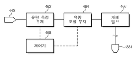
약액공급유닛(304)은 노즐(384)에 약액을 공급한다. 도5는 도3의 약액공급유닛을 개략적으로 보여주는 블럭도이다. 도5를 참조하면, 약액공급유닛(304)은 약액공급라인(420), 액 공급원(440), 그리고 유량조절부(460)를 포함한다. 약액공급라인(420)은 노즐(384) 및 액 공급원(440)에 연결된다, 액 공급원(440)에 제공된 약액은 약액공급라인(420)을 통해 노즐(384)로 공급된다. 유량조절부(460)는 약액공급라인(420)을 통해 노즐(384)로 공급되는 약액의 유량을 조절한다. 유량조절부(460)는 개폐밸브(466), 유량측정부재(462), 유량조절부재(464), 그리고 제어기(468)를 포함한다. 유량측정부재(462), 유량조절부재(464), 그리고 개폐밸브(466)는 약액이 흐르는 방향에 따라 약액공급라인(420)에 순차적으로 위치된다. 개폐밸브(466)는 노즐(384)과 인접하게 위치된다. 개폐밸브(466)는 약액의 토출 유무에 따라 약액공급라인(420)을 개폐한다. The chemical liquid supply unit 304 supplies the chemical liquid to the
유량측정부재(462)는 액 공급원(440)으로부터 약액공급라인(420)에 공급되는 약액의 유량을 측정한다. 유량측정부재(462)는 약액의 유량을 측정하고, 측정된 값을 제어기(468)로 제공한다. 예컨대, 유량측정부재(462)는 초음파 유량계일 수 있다. The flow
유량조절부재(464)는 약액공급라인(420)에서 노즐(384)로 공급되는 약액의 유량을 조절한다. 일 예에 의하면, 유량조절부재(464)는 가스의 가압력에 의해 개구율이 조절되는 정압밸브일 수 있다. 유량조절부재(464)는 고정량 공급방식과 피드백 공급방식으로 약액의 공급 유량을 조정한다. 여기서 고정량 공급방식은 유량조절부재(464)의 개구율을 고정하여 약액의 공급유량을 일정하게 유지시키는 방식이다. 피드백 공급방식은 변동되는 약액의 유량을 실시간으로 측정하고, 측정된 값에 따라 유량조절부재(464)의 개구율을 실시간으로 조절하여 약액의 공급유량을 일정하게 유지시키는 방식이다. 유량조절부재(464)는 약액이 공급되는 시간 경과에 따라 서로 상이한 공급방식으로 약액의 유량을 조절한다. 일 예에 의하면, 유량조절부재(464)는 약액의 초기 공급 시 고정량 공급방식으로 약액의 유량을 조절하고, 이후에 피드백 공급방식으로 약액의 유량을 조절한다. The flow
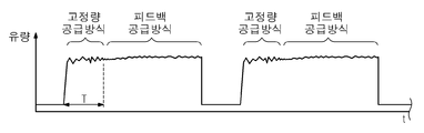
제어기(468)는 유량측정부재(462)와 유량조절부재(464)에 연결된다. 제어기(468)는 유량측정부재(462)로부터 측정된 유량 측정값을 기초로 하여 유량조절부재(464)를 제어한다. 제어기(468)는 약액이 공급되는 시계열적 단계에 따라 유량조절부재(464)가 고정량 공급방식 또는 피드백 공급방식을 가지도록 유량조절부재(464)를 제어한다. 도6은 도5의 약액공급유닛에 의해 공급되는 약액의 유량을 보여주는 표이다. 도6을 참조하면, 제어기(468)는 약액의 초기 공급 시 유량조절부재(464)가 고정량 공급방식으로 약액의 유량을 조절하도록 유량조절부재(464)를 제어한다. 기설정 시간이 경과되면, 제어기(468)는 유량조절부재(464)가 피드백 공급방식으로 약액의 유량을 조절하도록 유량조절부재(464)를 제어한다. 제어기(468)는 기설정 시간(T)이 경과되면, 유량측정부재(462)로부터 측정된 정보를 제공받아 유량의 변동사항에 대응하여 약액의 공급 유량이 일정하도록 유량조절부재(464)를 제어한다. 일 예에 의하면, 제어기(468)는 공급 유량의 오차범위가 기설정된 범위를 넘지 않도록 유량조절부재(464)를 제어한다. 고정량 공급방식으로 약액의 유량을 조정하는 기설정된 시간(T)은 약액의 유량이 공정에서 요구되는 유량에 도달되는 시간과 동일하거나, 이보다 길게 제공될 수 있다. 제어기(468)가 유량조절부재(464)를 고정량 공급방식으로 제어하는 기설정 시간(T)은 5초 일 수 있다.The
440: 액 공급원 420: 약액공급라인
460: 유량조절부 462: 유량측정부재
464: 유량조절부재 468: 제어기440: Liquid supply source 420: Chemical liquid supply line
460: Flow regulator 462: Flow measuring member
464: Flow control member 468:
Claims (2)
상기 액 공급원 및 노즐에 연결되는 약액공급라인과;
상기 약액공급라인에 설치되고, 약액의 유량이 일정하게 공급되도록 약액의 유량을 조절하는 유량조절부를 포함하되,
상기 유량조절부는 약액 토출 초기에 약액의 유량을 고정량 공급방식으로 조절하고, 이후에 약액의 유량을 피드백 공급방식으로 조절하는 약액공급유닛.A liquid supply source for supplying the chemical liquid;
A chemical liquid supply line connected to the liquid supply source and the nozzle;
And a flow rate adjusting unit installed in the chemical liquid supply line and adjusting a flow rate of the chemical liquid so that the flow rate of the chemical liquid is constantly supplied,
Wherein the flow rate regulator adjusts the flow rate of the chemical liquid at the initial stage of the chemical liquid supply to a fixed amount supply system and then adjusts the flow rate of the chemical liquid to a feedback supply system.
상기 유량조절부는,
상기 약액공급라인에 제공된 약액의 유량을 측정하는 유량측정부재와;
상기 약액공급라인에 제공된 약액의 유량을 조절하는 유량조절부재와;
상기 유량측정부재 및 상기 유량조절부재에 연결되고, 상기 유량조절부재를 상기 고정량 공급방식 또는 상기 피드백 공급방식으로 제어하는 제어기를 포함하되,
상기 제어기는 상기 고정량 공급방식으로 상기 유량조절부재를 제어 시 상기 유량조절부재의 개구율이 고정시키고, 상기 피드백 공급방식으로 상기 유량조절부재를 제어 시 상기 유량측정부재로부터 측정된 정보를 기초로 하여 상기 유량조절부재의 개구율을 조절하는 약액공급유닛.The method according to claim 1,
Wherein the flow-
A flow rate measuring member for measuring a flow rate of the chemical solution supplied to the chemical solution supply line;
A flow rate adjusting member for adjusting a flow rate of the chemical solution supplied to the chemical liquid supply line;
And a controller connected to the flow rate measuring member and the flow rate adjusting member and controlling the flow rate adjusting member to the fixed amount supply mode or the feedback supply mode,
Wherein the controller fixes the opening ratio of the flow rate adjusting member when the flow rate adjusting member is controlled by the fixed amount supplying system and controls the flow rate adjusting member based on information measured from the flow rate measuring member And controls the opening ratio of the flow rate controlling member.
Priority Applications (1)
| Application Number | Priority Date | Filing Date | Title |
|---|---|---|---|
| KR1020130001194A KR102149485B1 (en) | 2013-01-04 | 2013-01-04 | Unit for supplying chemical, Appratus and Method for treating substrate with the unit |
Applications Claiming Priority (1)
| Application Number | Priority Date | Filing Date | Title |
|---|---|---|---|
| KR1020130001194A KR102149485B1 (en) | 2013-01-04 | 2013-01-04 | Unit for supplying chemical, Appratus and Method for treating substrate with the unit |
Publications (2)
| Publication Number | Publication Date |
|---|---|
| KR20140089216A true KR20140089216A (en) | 2014-07-14 |
| KR102149485B1 KR102149485B1 (en) | 2020-08-31 |
Family
ID=51737469
Family Applications (1)
| Application Number | Title | Priority Date | Filing Date |
|---|---|---|---|
| KR1020130001194A KR102149485B1 (en) | 2013-01-04 | 2013-01-04 | Unit for supplying chemical, Appratus and Method for treating substrate with the unit |
Country Status (1)
| Country | Link |
|---|---|
| KR (1) | KR102149485B1 (en) |
Cited By (4)
| Publication number | Priority date | Publication date | Assignee | Title |
|---|---|---|---|---|
| KR101634686B1 (en) * | 2014-12-24 | 2016-07-08 | 주식회사 선익시스템 | Nozzle jet head module and nozzle jet system having the same |
| KR20190037805A (en) * | 2017-09-29 | 2019-04-08 | 세메스 주식회사 | Apparatus and Method for treating substrate |
| KR20200028590A (en) * | 2018-09-07 | 2020-03-17 | 세메스 주식회사 | Method and apparatus for treating substrate |
| US11772115B2 (en) | 2019-09-26 | 2023-10-03 | Semes Co., Ltd. | Substrate treating apparatus and treatment liquid dispensing method for controlling a temperature of treatment liquid |
Citations (5)
| Publication number | Priority date | Publication date | Assignee | Title |
|---|---|---|---|---|
| JPH11114474A (en) * | 1997-10-13 | 1999-04-27 | Dainippon Screen Mfg Co Ltd | Substrate treatment apparatus |
| KR20060029372A (en) * | 2004-10-01 | 2006-04-06 | 세메스 주식회사 | System and control method for supplying chemical |
| KR20060100634A (en) * | 2005-03-17 | 2006-09-21 | 세메스 주식회사 | Method for liquid mixing supply |
| KR20080094144A (en) * | 2007-04-19 | 2008-10-23 | 씨앤지하이테크 주식회사 | A solution supply method and chemical solution supply apparatus |
| KR20120015928A (en) * | 2010-08-13 | 2012-02-22 | 세메스 주식회사 | Nozzzle and apparatus for treating a substrate wi th the nozzle |
-
2013
- 2013-01-04 KR KR1020130001194A patent/KR102149485B1/en active IP Right Grant
Patent Citations (5)
| Publication number | Priority date | Publication date | Assignee | Title |
|---|---|---|---|---|
| JPH11114474A (en) * | 1997-10-13 | 1999-04-27 | Dainippon Screen Mfg Co Ltd | Substrate treatment apparatus |
| KR20060029372A (en) * | 2004-10-01 | 2006-04-06 | 세메스 주식회사 | System and control method for supplying chemical |
| KR20060100634A (en) * | 2005-03-17 | 2006-09-21 | 세메스 주식회사 | Method for liquid mixing supply |
| KR20080094144A (en) * | 2007-04-19 | 2008-10-23 | 씨앤지하이테크 주식회사 | A solution supply method and chemical solution supply apparatus |
| KR20120015928A (en) * | 2010-08-13 | 2012-02-22 | 세메스 주식회사 | Nozzzle and apparatus for treating a substrate wi th the nozzle |
Cited By (5)
| Publication number | Priority date | Publication date | Assignee | Title |
|---|---|---|---|---|
| KR101634686B1 (en) * | 2014-12-24 | 2016-07-08 | 주식회사 선익시스템 | Nozzle jet head module and nozzle jet system having the same |
| KR20190037805A (en) * | 2017-09-29 | 2019-04-08 | 세메스 주식회사 | Apparatus and Method for treating substrate |
| US10651059B2 (en) | 2017-09-29 | 2020-05-12 | Semes Co., Ltd. | Apparatus and method for treating substrate |
| KR20200028590A (en) * | 2018-09-07 | 2020-03-17 | 세메스 주식회사 | Method and apparatus for treating substrate |
| US11772115B2 (en) | 2019-09-26 | 2023-10-03 | Semes Co., Ltd. | Substrate treating apparatus and treatment liquid dispensing method for controlling a temperature of treatment liquid |
Also Published As
| Publication number | Publication date |
|---|---|
| KR102149485B1 (en) | 2020-08-31 |
Similar Documents
| Publication | Publication Date | Title |
|---|---|---|
| KR102063322B1 (en) | Apparatus and Method for treating a substrate | |
| KR101607521B1 (en) | Apparatus and Method for treating substrate | |
| KR101605715B1 (en) | Method for treating substrate | |
| KR102149485B1 (en) | Unit for supplying chemical, Appratus and Method for treating substrate with the unit | |
| KR20170134094A (en) | Apparatus and method for treating substrate | |
| KR102222456B1 (en) | Unit for supplying chemical, Apparatus and method for treating substrate with the unit | |
| KR101344930B1 (en) | Apparatus for treating a substrate | |
| KR20190019229A (en) | Cleaning liquid supplying unit, substrate treating apparatus including the same and substrate treating method | |
| KR102098599B1 (en) | Chemical supply unit | |
| KR101471540B1 (en) | Method and Apparatus for treating substrate | |
| KR20180002101A (en) | Apparatus and Method for treating substrate | |
| KR101884851B1 (en) | Apparatus for treating a substrate and method for controlling temperature of nozzle | |
| KR20180070220A (en) | Unit for supplying liquid and apparatus for treating a substrate with the unit | |
| KR20190089801A (en) | Cleaning liquid supplying unit, substrate treating apparatus including the same and substrate treating method | |
| KR102075674B1 (en) | Apparatus for treating chemical, Apparatus and Method for treating substrate with the same | |
| KR20150068761A (en) | Apparatus for treating substrate | |
| KR102409472B1 (en) | Apparatus for treating a substrate | |
| KR102489739B1 (en) | Apparatus for treating substrate and method for supplying treating liquid | |
| KR20180030010A (en) | Apparatus and Method for treating substrate with unit | |
| KR20200122763A (en) | Apparatus and method for treating substrate | |
| KR20180081700A (en) | Appratus for treating substrate | |
| WO2024090082A1 (en) | Substrate processing method and substrate processing device | |
| KR101993730B1 (en) | Apparatus and method fdr cleaning substrates | |
| KR101993732B1 (en) | Apparatus for treating substrate and method for setting nozzle position | |
| KR102063323B1 (en) | Unit supplying chemical, Apparatus and Method for treating substrate with the unit |
Legal Events
| Date | Code | Title | Description |
|---|---|---|---|
| A201 | Request for examination | ||
| AMND | Amendment | ||
| E902 | Notification of reason for refusal | ||
| AMND | Amendment | ||
| E601 | Decision to refuse application | ||
| AMND | Amendment | ||
| E902 | Notification of reason for refusal | ||
| AMND | Amendment | ||
| X701 | Decision to grant (after re-examination) | ||
| GRNT | Written decision to grant |