KR20140058058A - The battery module - Google Patents
The battery module Download PDFInfo
- Publication number
- KR20140058058A KR20140058058A KR1020120124605A KR20120124605A KR20140058058A KR 20140058058 A KR20140058058 A KR 20140058058A KR 1020120124605 A KR1020120124605 A KR 1020120124605A KR 20120124605 A KR20120124605 A KR 20120124605A KR 20140058058 A KR20140058058 A KR 20140058058A
- Authority
- KR
- South Korea
- Prior art keywords
- electrode tab
- battery
- negative electrode
- positive electrode
- battery cell
- Prior art date
Links
Images


Classifications
-
- H—ELECTRICITY
- H01—ELECTRIC ELEMENTS
- H01M—PROCESSES OR MEANS, e.g. BATTERIES, FOR THE DIRECT CONVERSION OF CHEMICAL ENERGY INTO ELECTRICAL ENERGY
- H01M50/00—Constructional details or processes of manufacture of the non-active parts of electrochemical cells other than fuel cells, e.g. hybrid cells
- H01M50/50—Current conducting connections for cells or batteries
- H01M50/502—Interconnectors for connecting terminals of adjacent batteries; Interconnectors for connecting cells outside a battery casing
-
- H—ELECTRICITY
- H01—ELECTRIC ELEMENTS
- H01M—PROCESSES OR MEANS, e.g. BATTERIES, FOR THE DIRECT CONVERSION OF CHEMICAL ENERGY INTO ELECTRICAL ENERGY
- H01M50/00—Constructional details or processes of manufacture of the non-active parts of electrochemical cells other than fuel cells, e.g. hybrid cells
- H01M50/50—Current conducting connections for cells or batteries
- H01M50/531—Electrode connections inside a battery casing
-
- H—ELECTRICITY
- H01—ELECTRIC ELEMENTS
- H01M—PROCESSES OR MEANS, e.g. BATTERIES, FOR THE DIRECT CONVERSION OF CHEMICAL ENERGY INTO ELECTRICAL ENERGY
- H01M50/00—Constructional details or processes of manufacture of the non-active parts of electrochemical cells other than fuel cells, e.g. hybrid cells
- H01M50/50—Current conducting connections for cells or batteries
- H01M50/543—Terminals
-
- Y—GENERAL TAGGING OF NEW TECHNOLOGICAL DEVELOPMENTS; GENERAL TAGGING OF CROSS-SECTIONAL TECHNOLOGIES SPANNING OVER SEVERAL SECTIONS OF THE IPC; TECHNICAL SUBJECTS COVERED BY FORMER USPC CROSS-REFERENCE ART COLLECTIONS [XRACs] AND DIGESTS
- Y02—TECHNOLOGIES OR APPLICATIONS FOR MITIGATION OR ADAPTATION AGAINST CLIMATE CHANGE
- Y02E—REDUCTION OF GREENHOUSE GAS [GHG] EMISSIONS, RELATED TO ENERGY GENERATION, TRANSMISSION OR DISTRIBUTION
- Y02E60/00—Enabling technologies; Technologies with a potential or indirect contribution to GHG emissions mitigation
- Y02E60/10—Energy storage using batteries
Landscapes
- Chemical & Material Sciences (AREA)
- Chemical Kinetics & Catalysis (AREA)
- Electrochemistry (AREA)
- General Chemical & Material Sciences (AREA)
- Connection Of Batteries Or Terminals (AREA)
- Battery Mounting, Suspending (AREA)
Abstract
Description
본 발명은 충전 및 방전이 가능한 배터리셀(또는 서브모듈)이 다수개가 전기적으로 연결된 배터리 모듈에 관한 것이다.
The present invention relates to a battery module in which a plurality of battery cells (or submodules) capable of charging and discharging are electrically connected.
최근, 충방전이 가능한 이차전지는 와이어리스 모바일 기기의 에너지원으로 광범위하게 사용되고 있다.BACKGROUND ART [0002] In recent years, rechargeable secondary batteries have been widely used as energy sources for wireless mobile devices.
또한, 이차전지는 화석 연료를 사용하는 기존의 가솔린 차량, 디젤 차량 등의 대기오염 등을 해결하기 위한 방안으로 제시되고 있는 전기자동차(EV), 하이브리드 전기자동차(HEV) 등의 동력원으로서도 주목받고 있다.The secondary battery is also attracting attention as a power source for an electric vehicle (EV) and a hybrid electric vehicle (HEV), which are proposed as solutions for the air pollution of existing gasoline vehicles and diesel vehicles using fossil fuels .
소형 모바일 기기에서는 디바이스 1 대당 하나 또는 두서너 개의 배터리 셀들이 사용됨에 비하여, 자동차 등과 같은 중대형 디바이스에서는 고출력 대용량의 필요성으로 인해, 단위전지로서 다수의 배터리 셀을 전기적으로 연결한 중대형 전지팩이 사용된다.In a small-sized mobile device, one or a few battery cells are used per device, whereas a middle- or large-sized battery pack such as an automobile uses a middle- or large-sized battery pack in which a plurality of battery cells are electrically connected as a unit battery due to the necessity of a large-
중대형 전지팩은 가능하면 작은 크기와 중량으로 제조되는 것이 바람직하므로, 높은 집적도로 적층될 수 있고 용량 대비 중량이 작은 각형 전지, 파우치형 전지 등이 중대형 전지팩의 배터리 셀로서 주로 사용되고 있다. 그 중에서도, 중량이 작고 전해액의 누액 가능성이 적으며 제조비가 저렴한 파우치형 전지가 특히 많은 관심을 모으고 있다.Since the middle- or large-sized battery pack is preferably manufactured in a small size and weight, a prismatic battery, a pouch-type battery, and the like, which can be stacked with a high degree of integration and have a small weight to capacity ratio, are mainly used as the battery cells of the middle- or large-sized battery pack. Among them, a pouch type battery having a small weight, a low possibility of electrolyte leakage, and a low manufacturing cost is particularly attracting much attention.
한편, 하이브리드 자동차 등 고출력의 리튬 전지가 요구되는 경우에 배터리셀(또는 서브모듈)을 수십에서 수백 개 적층하고, 이를 직렬 또는 병렬 연결하여 고전압 또는 고전류를 얻게 된다.On the other hand, when a high output lithium battery such as a hybrid automobile is required, several tens to hundreds of battery cells (or sub-modules) are stacked and connected in series or parallel to obtain a high voltage or a high current.
그리고, 종래기술 US 20110135970 A1에는 배터리셀 적층체에 있어서, 서로 마주보는 일측 배터리셀과 타측 배터리셀을 버스 바와 같은 연결 부재에 의해 전기적으로 연결하는 기술이 개시되어 있다.In the prior art US 20110135970 A1, a technique of electrically connecting one side battery cell and the other side battery cell facing each other by a connecting member such as a bus bar in a battery cell stack body is disclosed.
그러나 종래기술은 버스 바와 같은 연결 부재를 이용함으로써, 제조비용이 증가되는 문제점이 있다.
However, the prior art uses a connecting member such as a bus bar, which increases the manufacturing cost.
본 발명은 상기와 같은 문제점을 해결하기 위하여 안출된 것으로, 별도의 연결 부재를 이용하지 않고 배터리셀 간을 전기적으로 연결할 수 있는 배터리 모듈을 제공하기 위한 것이다.
SUMMARY OF THE INVENTION The present invention has been made in order to solve the above problems, and it is an object of the present invention to provide a battery module which can electrically connect battery cells without using a separate connecting member.
본 발명의 실시예에 따른 배터리 모듈은 외부로 양극탭과 음극탭이 돌출 형성되는 배터리셀;을 포함하며, 상기 양극탭과 음극탭 중 적어도 하나의 단부에 절개홈이 형성되어 한 쌍의 절개부로 분리되고, 상기 배터리셀이 다수개 적층되어 전기적으로 연결된다.A battery module according to an embodiment of the present invention includes a battery cell having a positive electrode tab and a negative electrode tab protruded from the outside, wherein at least one of the positive electrode tab and the negative electrode tab has a cut- And a plurality of the battery cells are stacked and electrically connected.
또한, 상기 양극탭과 음극탭은 상기 절개홈이 직사각형 형태로 형성된다.In addition, the positive electrode tab and the negative electrode tab are formed in a rectangular shape.
또한, 상기 양극탭과 음극탭은 상기 절개홈의 모퉁이가 일정 곡률을 가지고 절곡된 형태로 형성된다.In addition, the positive electrode tab and the negative electrode tab are formed in a shape in which the corners of the incision grooves are bent with a certain curvature.
또한, 상기 배터리 모듈은 상기 배터리셀간에 서로 마주보는 상기 배터리셀의 양극탭에 구성된 절개부와 다른 배터리셀의 음극탭에 구성된 절개부가 서로를 향해 벤딩되며 그 면이 결합되어 형성되는 제1결합부에 의해 직렬 연결된다.In addition, the battery module may include a cut-out portion formed in the positive electrode tab of the battery cell facing the battery cells and a cut-out portion formed in the negative electrode tab of the other battery cell bent toward each other, Respectively.
또한, 상기 제1결합부에서 상기 절개부의 면이 용접에 의해 결합된다.Further, the surface of the incision portion is welded to the first engagement portion.
또한, 상기 배터리 모듈은 상기 배터리셀의 양극탭이 다른 배터리셀의 양극탭과 결합되고 상기 배터리셀의 음극탭이 다른 배터리셀의 음극탭과 결합되어 병렬 연결된 서브모듈이 다수개 적층되며, 상기 서브모듈들은 상기 서브모듈간에 서로 마주보는 상기 서브모듈의 배터리셀의 양극탭에 구성된 절개부와 다른 서브모듈의 배터리셀의 음극탭에 구성된 절개부가 서로를 향해 벤딩되며 그 면이 결합되어 형성되는 제2결합부에 의해 직렬 연결된다.In addition, the battery module has a plurality of submodules in which a positive electrode tab of the battery cell is coupled to a positive electrode tab of another battery cell, a negative electrode tab of the battery cell is coupled with a negative electrode tab of another battery cell, Modules are formed by bending the cut-out portion formed on the positive electrode tab of the battery cell of the sub-module facing each other and the cut-out portion formed on the negative electrode tab of the battery cell of the other sub-module, And are connected in series by a coupling portion.
또한, 상기 제2결합부에서 상기 절개부의 면이 용접에 의해 결합된다.
Further, the surface of the incision portion is welded to the second engagement portion.
이에 따라, 본 발명의 실시예에 따른 배터리 모듈은 양극탭과 음극탭의 간단한 변형에 의해 배터리셀들을 전기적으로 연결함으로써, 배터리셀들을 전기적인 연결에 별도의 연결 부재가 필요하지 않아 제조비용이 감소되는 효과가 있다.
Accordingly, in the battery module according to the embodiment of the present invention, since the battery cells are electrically connected by simple deformation of the positive electrode tab and the negative electrode tab, no separate connecting member is required for electrically connecting the battery cells, .
도 1은 본 발명의 실시예 1에 따른 배터리 모듈의 사시도
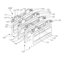
도 2는 본 발명의 실시예 1에 따른 배터리 모듈의 분해사시도
도 3은 본 발명의 실시예 2에 따른 배터리 모듈의 사시도
도 4는 본 발명의 실시예 2에 따른 배터리 모듈의 분해사시도1 is a perspective view of a battery module according to a first embodiment of the present invention;
Fig. 2 is an exploded perspective view of the battery module according to the first embodiment of the present invention. Fig.
3 is a perspective view of a battery module according to a second embodiment of the present invention.
4 is an exploded perspective view of the battery module according to the second embodiment of the present invention.
이하, 본 발명의 기술적 사상을 첨부된 도면을 사용하여 더욱 구체적으로 설명한다.Hereinafter, the technical idea of the present invention will be described more specifically with reference to the accompanying drawings.
첨부된 도면은 본 발명의 기술적 사상을 더욱 구체적으로 설명하기 위하여 도시한 일예에 불과하므로 본 발명의 기술적 사상이 첨부된 도면의 형태에 한정되는 것은 아니다.
BRIEF DESCRIPTION OF THE DRAWINGS The accompanying drawings, which are included to provide a further understanding of the technical concept of the present invention, are incorporated in and constitute a part of the specification, and are not intended to limit the scope of the present invention.
도 1은 본 발명의 실시예 1에 따른 배터리 모듈의 사시도, 도 2는 본 발명의 실시예 1에 따른 배터리 모듈의 분해사시도이다.FIG. 1 is a perspective view of a battery module according to Embodiment 1 of the present invention, and FIG. 2 is an exploded perspective view of a battery module according to Embodiment 1 of the present invention.
도 1 내지 도 2에 도시된 바와 같이, 본 발명의 실시예 1에 따른 배터리 모듈(1000)은 일정간격 이격되어 나란히 적층되는 다수개의 배터리셀(110)과, 배터리셀(110)간을 전기적으로 연결하는 구조를 포함할 수 있다.As shown in FIGS. 1 and 2, a
먼저, 본 발명의 실시예 1에 따른 배터리 모듈(1000)에 구성된 배터리셀(110)에 대해 설명하자면 다음과 같다.First, the
배터리셀(110)은 전극조립체(미도시), 케이스(111)를 포함하여 구성되며, 양극탭(120) 및 음극탭(130)이 외부로 돌출 형성된다.The
전극조립체는 양극판과 음극판 사이에 분리막이 개재되는 구성으로, 양극판에 양극탭(120)이 돌출형성되며, 음극판에 음극탭(130)이 돌출 형성된다.The electrode assembly has a separator interposed between the positive electrode plate and the negative electrode plate. The positive electrode tab protrudes from the positive electrode plate, and the negative electrode tab protrudes from the negative electrode plate.
양극탭(120) 및 음극탭(130)은 외부에 전원 연결되기 위한 역할을 한다.The
케이스(111)는 양극탭(120) 및 음극탭(130)이 외부로 돌출되도록 내부에 전극조립체가 수납된다. 더욱 상세하게, 케이스(111)는 내부에 형성된 공간부의 가장자리를 따라 실링부재가 도포되어 내부에 전극조립체가 밀봉된다. 또한, 케이스(111)는 알루미늄이나 알루미늄 합금 또는 니켈이 도금된 스틸 등과 같은 도전성 금속재로 이루어질 수 있다.The
도면에는 케이스(111)가 파우치 형태이며, 양극탭(120) 및 음극탭(130)이 모두 일측에 돌출된 예를 도시하였으나, 본 발명은 이에 한정되지 아니한다.Although the
다음으로, 본 발명의 실시예 1에 따른 배터리 모듈(1000)에 구성된 배터리셀(110)간을 전기적으로 연결하는 구조에 대해 설명하자면 다음과 같다.Next, a structure for electrically connecting the
도 1 내지 도 2를 참조하면, 배터리셀(110)의 양극탭(120)과 음극탭(130) 중 적어도 하나의 단부에 절개홈(121, 131)이 형성되어 양극탭에 구성되는 한 쌍의 절개부(122, 123)와 음극탭에 구성되는 한 쌍의 절개부(132, 133)로 분리된다.1 and 2,
또한, 그 배터리셀(110)이 다수개 적층된 후, 그 배터리셀(110)의 적층방향으로 서로 마주보는 배터리셀(110)의 양극탭(120)에 구성된 한 쌍의 절개부(122, 123) 중 하나의 절개부(122)와 다른 배터리셀(110)의 음극탭(130)에 구성된 한 쌍의 절개부(132, 133) 중 하나의 절개부(132)가 서로를 향해 벤딩되며 그 면이 결합되어 형성되는 제1결합부(140)에 의해 직렬 연결된다.A plurality of
물론, 배터리셀(110)의 양극탭(120)에 구성된 한 쌍의 절개부(122, 123) 중 다른 하나의 절개부(123)와 다른 배터리셀(110)의 음극탭(130)에 구성된 한 쌍의 절개부(132, 133) 중 다른 하나의 절개부(133)가 서로를 향해 벤딩되며 그 면이 결합되어 형성되는 제1결합부(140)에 의해 직렬 연결될 수 있다.Of course, when the cut-out
이 때, 양극탭(120)과 음극탭(130)은 각각의 절개부(122, 123, 132, 133)의 벤딩이 간편하게 이루어질 수 있도록 각각의 절개홈(121, 131)이 직사각형 형태로 함몰 형성될 수 있다.The
또한, 양극탭(120)과 음극탭(130)은 각각의 절개부(122, 123, 132, 133)의 벤딩에 의해 그 모퉁이가 파단되는 것을 방지할 수 있도록 각각의 절개홈(121, 131)의 모퉁이가 일정 곡률을 가지고 절곡된 형태로 형성되는 것이 바람직하다.The
또한, 제1결합부(140)에서 서로 마주보는 배터리셀(110)의 양극탭(120)에 구성된 한 쌍의 절개부(122, 123) 중 하나의 절개부(122)의 면과 배터리셀(110)의 음극탭(130)에 구성된 한 쌍의 절개부(132, 133) 중 하나의 절개부(132)의 면이 용접에 의해 결합된다. 이 때, 용접은 제조시간이 적게 소요될 수 있도록 순간용접이 가능한 레이저 용접이나 자외선 용접을 이용하는 것이 바람직하다.The surface of one of the
이에 따라, 본 발명의 실시예 1에 따른 배터리 모듈(1000)은 양극탭(120)과 음극탭(130)의 간단한 변형에 의해 배터리셀(110)들을 전기적으로 연결함으로써, 배터리셀들(110)을 전기적인 연결에 별도의 연결 부재가 필요하지 않아 제조비용이 감소되는 효과가 있다.The
한편, 도 1 내지 도 2에는 배터리셀(110)들이 상호 직렬 연결된 실시예가 도시되었으나, 본 발명은 이에 한정되지 않고, 배터리셀(110)들이 상호 병렬 연결되거나 직렬과 병렬의 조합으로 연결될 수 있다. 이 때, 배터리셀(110)들이 병렬 연결되거나 직렬과 병렬의 조합으로 연결되는 경우에도, 본 발명의 실시예 1에 따른 양극탭(120)과 음극탭(130)을 이용하여 배터리셀(110)들을 상호 간편하게 연결할 수 있다.
1 and 2 show an embodiment in which
도 3은 본 발명의 실시예 2에 따른 배터리 모듈의 사시도, 도 4는 본 발명의 실시예 2에 따른 배터리 모듈의 분해사시도이다.FIG. 3 is a perspective view of a battery module according to a second embodiment of the present invention, and FIG. 4 is an exploded perspective view of a battery module according to a second embodiment of the present invention.
도 3 내지 도 4에 도시된 바와 같이, 본 발명의 실시예 2에 따른 배터리 모듈(1000`)은 2개의 배터리셀(110)이 서로 병렬 연결되는 서브모듈(100)이 다수개 적층되며, 그 서브모듈(100)간을 직렬 연결하기 위한 구성이 개시된다.3 to 4, the battery module 1000 'according to the second embodiment of the present invention includes a plurality of
먼저, 본 발명의 실시예 2에 따른 배터리 모듈(1000`)에 구성된 서브모듈(100)에 대해 설명하자면 다음과 같다.First, the
서브모듈(100)은 배터리셀(110)의 양극탭(120)이 다른 배터리셀(110)의 양극탭(120)과 결합되고 배터리셀(110)의 음극탭(130)이 다른 배터리셀(110)의 음극탭(130)과 결합되어 병렬 연결된다. 즉, 양극탭(120)과 양극탭(120)이 결합되고, 음극탭(130)과 음극탭(130)이 결합되는 것이다. 또한 서브모듈(100)을 이루는 배터리셀(110) 사이에는 배터리셀(110)이 이격된 간격을 유지하기 위한 밀착부재가 구비될 수 있다.The
다음으로, 본 발명의 실시예 2에 따른 배터리 모듈(1000`)에 구성된 서브모듈(100)간을 직렬 연결하는 구조에 대해 설명하자면 다음과 같다.Next, a structure for serially connecting the
도 5 내지 도 6을 참조하면, 서브모듈(100)들은 서브모듈(100)간에 서로 마주보는 배터리셀(110)의 양극탭과 음극탭 중 적어도 하나의 단부에 절개홈(121, 131)이 형성되어 양극탭에 구성되는 한 쌍의 절개부(122, 123)와 음극탭(130)에 구성되는 한 쌍의 절개부(132, 133)로 구성된다.5 to 6, the
또한, 서브모듈(100)들은 서브모듈(100)간에 서로 마주보는 서브모듈(100)의 배터리셀(110)의 양극탭(120)에 구성된 한 쌍의 절개부(122, 123)중 하나의 절개부(122)와 다른 서브모듈(100)의 배터리셀(110)의 음극탭(130)에 구성된 한 쌍의 절개부(132, 133)중 하나의 절개부(132)가 서로를 향해 결합되며 그 면이 결합되어 형성되는 제2결합부(150)에 의해 직렬 연결된다.The
이 때, 제2결합부(150)에서 서브모듈(100)의 배터리셀(110)의 양극탭(120)에 구성된 한 쌍의 절개부(122, 123)중 하나의 절개부(122)의 면과 다른 서브모듈(100)의 배터리셀(110)의 음극탭(130)에 구성된 한 쌍의 절개부(132, 133)중 하나의 절개부(132)의 면이 용접에 의해 결합된다. 이 때, 용접은 제조시간이 적게 소요될 수 있도록 순간용접이 가능한 레이저 용접이나 자외선 용접을 이용하는 것이 바람직하다.At this time, the surface of one of the pair of
이에 따라, 본 발명의 실시예 2에 따른 배터리 모듈(1000`)은 별도의 연결부재를 이용하지 않고 하나의 배터리 모듈(1000`)에서 직렬 및 병렬 연결이 가능한 장점이 있다.Accordingly, the battery module 1000 'according to the second embodiment of the present invention is advantageous in that it can be connected in series and in parallel in one battery module 1000' without using a separate connecting member.
본 발명은 상기한 실시예에 한정되지 아니하며, 적용범위가 다양함은 물론이고, 청구범위에서 청구하는 본 발명의 요지를 벗어남이 없이 다양한 변형 실시가 가능한 것은 물론이다.It will be understood by those skilled in the art that various changes in form and details may be made therein without departing from the spirit and scope of the invention as defined by the appended claims.
1000, 1000` : 배터리 모듈
100 : 서브모듈
110 : 배터리셀 111 : 케이스
120 : 양극탭 130 : 음극탭
121, 131 : 절개홈 122, 123, 132, 133 : 절개부
140 : 제1결합부 150 : 제2결합부1000, 1000`: Battery module
100: Submodule
110: battery cell 111: case
120: positive electrode tab 130: negative electrode tab
121, 131: cutting
140: first coupling portion 150: second coupling portion
Claims (7)
상기 양극탭과 음극탭 중 적어도 하나의 단부에 절개홈이 형성되어 한 쌍의 절개부로 분리되고,
상기 배터리셀이 다수개 적층되어 전기적으로 연결되는 배터리 모듈.
And a battery cell in which a positive electrode tab and a negative electrode tab are protruded from the outside,
Wherein at least one of the positive electrode tab and the negative electrode tab has a cutout groove formed therein and separated into a pair of cutouts,
Wherein the plurality of battery cells are stacked and electrically connected to each other.
상기 절개홈이 직사각형 형태로 형성되는 배터리 모듈.
The battery pack according to claim 1, wherein the positive electrode tab and the negative electrode tab
Wherein the cut-out groove is formed in a rectangular shape.
상기 절개홈의 모퉁이가 일정 곡률을 가지고 절곡된 형태로 형성되는 배터리 모듈.
The battery pack according to claim 2, wherein the positive electrode tab and the negative electrode tab
And a corner of the incision groove is bent to have a predetermined curvature.
상기 배터리셀간에 서로 마주보는 상기 배터리셀의 양극탭에 구성된 절개부와 다른 배터리셀의 음극탭에 구성된 절개부가 서로를 향해 벤딩되며 그 면이 결합되어 형성되는 제1결합부에 의해 직렬 연결되는 배터리 모듈.
The battery module according to claim 1, wherein the battery module
A cut-away portion formed in the positive electrode tab of the battery cell facing the battery cells and a cut-out portion formed in the negative electrode tab of the other battery cell are bent toward each other, module.
상기 제1결합부에서 상기 절개부의 면이 용접에 의해 결합되는 배터리 모듈.
5. The method of claim 4,
And a surface of the cutout portion is welded to the first engagement portion.
상기 배터리셀의 양극탭이 다른 배터리셀의 양극탭과 결합되고 상기 배터리셀의 음극탭이 다른 배터리셀의 음극탭과 결합되어 병렬 연결된 서브모듈이 다수개 적층되며,
상기 서브모듈들은 상기 서브모듈간에 서로 마주보는 상기 서브모듈의 배터리셀의 양극탭에 구성된 절개부와 다른 서브모듈의 배터리셀의 음극탭에 구성된 절개부가 서로를 향해 벤딩되며 그 면이 결합되어 형성되는 제2결합부에 의해 직렬 연결되는 배터리 모듈.
The battery module according to claim 1, wherein the battery module
A plurality of submodules in which a positive electrode tab of the battery cell is coupled with a positive electrode tab of another battery cell and a negative electrode tab of the battery cell is coupled with a negative electrode tab of another battery cell,
Wherein the submodules are formed by bending the incision part formed on the positive electrode tab of the battery cell of the submodule facing each other and the incision part formed on the negative electrode tab of the battery cell of another submodule facing each other, And a battery module connected in series by the second coupling portion.
상기 제2결합부에서 상기 절개부의 면이 용접에 의해 결합되는 배터리 모듈.The method according to claim 6,
And a surface of the cutout portion is welded to the second engagement portion.
Priority Applications (1)
| Application Number | Priority Date | Filing Date | Title |
|---|---|---|---|
| KR1020120124605A KR102113156B1 (en) | 2012-11-06 | 2012-11-06 | The battery module |
Applications Claiming Priority (1)
| Application Number | Priority Date | Filing Date | Title |
|---|---|---|---|
| KR1020120124605A KR102113156B1 (en) | 2012-11-06 | 2012-11-06 | The battery module |
Publications (2)
| Publication Number | Publication Date |
|---|---|
| KR20140058058A true KR20140058058A (en) | 2014-05-14 |
| KR102113156B1 KR102113156B1 (en) | 2020-05-20 |
Family
ID=50888540
Family Applications (1)
| Application Number | Title | Priority Date | Filing Date |
|---|---|---|---|
| KR1020120124605A KR102113156B1 (en) | 2012-11-06 | 2012-11-06 | The battery module |
Country Status (1)
| Country | Link |
|---|---|
| KR (1) | KR102113156B1 (en) |
Cited By (3)
| Publication number | Priority date | Publication date | Assignee | Title |
|---|---|---|---|---|
| CN110102609A (en) * | 2019-05-24 | 2019-08-09 | 广西超威鑫锋能源有限公司 | A kind of curved tab mold of side plug-in type |
| DE102019116701A1 (en) | 2018-06-19 | 2019-12-19 | Sk Innovation Co., Ltd. | BATTERY CELL WITH A VARIETY OF ELECTRODES AND BATTERY MODULE WITH SUCH A BATTERY CELL |
| CN110620209A (en) * | 2018-06-19 | 2019-12-27 | Sk新技术株式会社 | Battery having a plurality of electrodes and battery module using the same |
Citations (5)
| Publication number | Priority date | Publication date | Assignee | Title |
|---|---|---|---|---|
| KR20060072029A (en) * | 2004-12-22 | 2006-06-27 | 에스케이 주식회사 | High power lithium unit cell and high power lithium battery pack having the same |
| US20110135970A1 (en) | 2009-12-03 | 2011-06-09 | Samsung Sdi Co., Ltd. | Circuit substrate module and battery module using the same |
| KR101074992B1 (en) * | 2011-01-05 | 2011-10-18 | 박봉찬 | Battery cell electrode for storage battery |
| KR20120072575A (en) * | 2010-12-24 | 2012-07-04 | 삼성에스디아이 주식회사 | Electrode assembly and secondary battery with the same |
| KR20120076020A (en) * | 2010-12-29 | 2012-07-09 | 에스케이이노베이션 주식회사 | Battery module and tab ultrasonic wave welding method |
-
2012
- 2012-11-06 KR KR1020120124605A patent/KR102113156B1/en active IP Right Grant
Patent Citations (5)
| Publication number | Priority date | Publication date | Assignee | Title |
|---|---|---|---|---|
| KR20060072029A (en) * | 2004-12-22 | 2006-06-27 | 에스케이 주식회사 | High power lithium unit cell and high power lithium battery pack having the same |
| US20110135970A1 (en) | 2009-12-03 | 2011-06-09 | Samsung Sdi Co., Ltd. | Circuit substrate module and battery module using the same |
| KR20120072575A (en) * | 2010-12-24 | 2012-07-04 | 삼성에스디아이 주식회사 | Electrode assembly and secondary battery with the same |
| KR20120076020A (en) * | 2010-12-29 | 2012-07-09 | 에스케이이노베이션 주식회사 | Battery module and tab ultrasonic wave welding method |
| KR101074992B1 (en) * | 2011-01-05 | 2011-10-18 | 박봉찬 | Battery cell electrode for storage battery |
Cited By (7)
| Publication number | Priority date | Publication date | Assignee | Title |
|---|---|---|---|---|
| DE102019116701A1 (en) | 2018-06-19 | 2019-12-19 | Sk Innovation Co., Ltd. | BATTERY CELL WITH A VARIETY OF ELECTRODES AND BATTERY MODULE WITH SUCH A BATTERY CELL |
| CN110620209A (en) * | 2018-06-19 | 2019-12-27 | Sk新技术株式会社 | Battery having a plurality of electrodes and battery module using the same |
| KR20190143407A (en) | 2018-06-19 | 2019-12-30 | 에스케이이노베이션 주식회사 | Battery having multi electrode-lead and The battery module |
| KR20210109494A (en) | 2018-06-19 | 2021-09-06 | 에스케이이노베이션 주식회사 | Battery having multi electrode-lead and The battery module |
| US11545706B2 (en) | 2018-06-19 | 2023-01-03 | Sk Innovation Co., Ltd. | Battery cell having a plurality of electrodes and battery module using the same |
| CN110102609A (en) * | 2019-05-24 | 2019-08-09 | 广西超威鑫锋能源有限公司 | A kind of curved tab mold of side plug-in type |
| CN110102609B (en) * | 2019-05-24 | 2023-09-22 | 广西超威能源有限公司 | Side inserted type lug bending die |
Also Published As
| Publication number | Publication date |
|---|---|
| KR102113156B1 (en) | 2020-05-20 |
Similar Documents
| Publication | Publication Date | Title |
|---|---|---|
| EP2927986B1 (en) | Battery cell having missing portion and battery pack comprising same | |
| JP6510633B2 (en) | Battery pack case with efficient cooling structure | |
| EP3151307B1 (en) | Battery module and battery pack comprising same | |
| US7405022B2 (en) | Secondary battery pack having configuration of alternative orientation | |
| US9741984B2 (en) | Battery module of novel structure and battery pack comprising the same | |
| EP2535962B1 (en) | Battery module having enhanced welding reliability and medium or large battery pack including same | |
| KR101547814B1 (en) | Battery Module Having Indirect Air-Cooling Structure | |
| EP2779269B1 (en) | Battery cell having a novel structure | |
| KR101509474B1 (en) | Battery Assembly Having Single Electrode Terminal Connecting Part | |
| JP7484992B2 (en) | Energy storage element | |
| EP2765632A1 (en) | Battery module assembly having improved reliability and medium or large-sized battery pack including same | |
| US10367175B2 (en) | Multicavity battery module | |
| KR102055852B1 (en) | Pouch-typed secondary battery comprising modified leads and battery module comprising the same | |
| KR20140044440A (en) | Battery pack | |
| CN108123073B (en) | Laminated battery for series connection and battery pack | |
| EP3731302B1 (en) | Battery module, battery pack comprising same battery module, and vehicle comprising same battery pack | |
| KR20150137840A (en) | Unit battery module and Battery module having the same | |
| KR20190143407A (en) | Battery having multi electrode-lead and The battery module | |
| KR102113156B1 (en) | The battery module | |
| KR20150036897A (en) | Battery Module Having Metal Printed Circuit Board | |
| KR20140019951A (en) | Battery module with bus-bar for changing position of output terminal | |
| KR101485180B1 (en) | Battery module comprising several unit batteries, and battery pack including the same | |
| KR101891481B1 (en) | Connecting Structure of Secondary Battery Cell | |
| KR101906923B1 (en) | Battery Module and Laser welding method for Battery Module | |
| CN116249652A (en) | Connecting part, battery monomer, battery and electric equipment |
Legal Events
| Date | Code | Title | Description |
|---|---|---|---|
| A201 | Request for examination | ||
| E902 | Notification of reason for refusal | ||
| E902 | Notification of reason for refusal | ||
| E701 | Decision to grant or registration of patent right | ||
| GRNT | Written decision to grant |