KR20140020782A - Method of manufacturing semiconductor device, method of processing substrate and substrate processing apparatus - Google Patents
Method of manufacturing semiconductor device, method of processing substrate and substrate processing apparatus Download PDFInfo
- Publication number
- KR20140020782A KR20140020782A KR1020130094066A KR20130094066A KR20140020782A KR 20140020782 A KR20140020782 A KR 20140020782A KR 1020130094066 A KR1020130094066 A KR 1020130094066A KR 20130094066 A KR20130094066 A KR 20130094066A KR 20140020782 A KR20140020782 A KR 20140020782A
- Authority
- KR
- South Korea
- Prior art keywords
- pressure
- processing
- gas
- flow rate
- film
- Prior art date
Links
- 238000012545 processing Methods 0.000 title claims abstract description 239
- 238000000034 method Methods 0.000 title claims abstract description 118
- 239000000758 substrate Substances 0.000 title claims abstract description 115
- 239000004065 semiconductor Substances 0.000 title claims abstract description 13
- 238000004519 manufacturing process Methods 0.000 title claims abstract description 11
- 230000008569 process Effects 0.000 claims abstract description 102
- 238000010926 purge Methods 0.000 claims abstract description 70
- 238000002360 preparation method Methods 0.000 claims 1
- 230000015556 catabolic process Effects 0.000 abstract 1
- 238000006731 degradation reaction Methods 0.000 abstract 1
- 239000007789 gas Substances 0.000 description 242
- 235000012431 wafers Nutrition 0.000 description 77
- 239000010408 film Substances 0.000 description 34
- 239000002994 raw material Substances 0.000 description 33
- 238000012546 transfer Methods 0.000 description 26
- 230000007246 mechanism Effects 0.000 description 21
- 238000006243 chemical reaction Methods 0.000 description 17
- 239000011261 inert gas Substances 0.000 description 17
- 230000008859 change Effects 0.000 description 15
- 238000006073 displacement reaction Methods 0.000 description 10
- 238000002407 reforming Methods 0.000 description 10
- 239000007788 liquid Substances 0.000 description 9
- 229910052760 oxygen Inorganic materials 0.000 description 9
- 239000001301 oxygen Substances 0.000 description 8
- 238000003860 storage Methods 0.000 description 8
- 239000000376 reactant Substances 0.000 description 7
- 230000004913 activation Effects 0.000 description 6
- 238000001816 cooling Methods 0.000 description 6
- 238000010586 diagram Methods 0.000 description 6
- 230000003028 elevating effect Effects 0.000 description 6
- 238000010438 heat treatment Methods 0.000 description 6
- 238000011084 recovery Methods 0.000 description 6
- 238000012423 maintenance Methods 0.000 description 5
- 238000003672 processing method Methods 0.000 description 5
- IJGRMHOSHXDMSA-UHFFFAOYSA-N Atomic nitrogen Chemical compound N#N IJGRMHOSHXDMSA-UHFFFAOYSA-N 0.000 description 4
- XUIMIQQOPSSXEZ-UHFFFAOYSA-N Silicon Chemical compound [Si] XUIMIQQOPSSXEZ-UHFFFAOYSA-N 0.000 description 4
- QVGXLLKOCUKJST-UHFFFAOYSA-N atomic oxygen Chemical compound [O] QVGXLLKOCUKJST-UHFFFAOYSA-N 0.000 description 4
- 239000000460 chlorine Substances 0.000 description 4
- 238000004140 cleaning Methods 0.000 description 4
- 230000007423 decrease Effects 0.000 description 4
- 230000000694 effects Effects 0.000 description 4
- 229910052710 silicon Inorganic materials 0.000 description 4
- ZMANZCXQSJIPKH-UHFFFAOYSA-N Triethylamine Chemical compound CCN(CC)CC ZMANZCXQSJIPKH-UHFFFAOYSA-N 0.000 description 3
- 230000015572 biosynthetic process Effects 0.000 description 3
- 229910052799 carbon Inorganic materials 0.000 description 3
- 239000000498 cooling water Substances 0.000 description 3
- 230000008021 deposition Effects 0.000 description 3
- 238000005530 etching Methods 0.000 description 3
- 239000000463 material Substances 0.000 description 3
- 239000010703 silicon Substances 0.000 description 3
- 238000011144 upstream manufacturing Methods 0.000 description 3
- KDSNLYIMUZNERS-UHFFFAOYSA-N 2-methylpropanamine Chemical compound CC(C)CN KDSNLYIMUZNERS-UHFFFAOYSA-N 0.000 description 2
- QUSNBJAOOMFDIB-UHFFFAOYSA-N Ethylamine Chemical compound CCN QUSNBJAOOMFDIB-UHFFFAOYSA-N 0.000 description 2
- BAVYZALUXZFZLV-UHFFFAOYSA-N Methylamine Chemical compound NC BAVYZALUXZFZLV-UHFFFAOYSA-N 0.000 description 2
- 150000001412 amines Chemical class 0.000 description 2
- 238000013459 approach Methods 0.000 description 2
- 238000009530 blood pressure measurement Methods 0.000 description 2
- HQABUPZFAYXKJW-UHFFFAOYSA-N butan-1-amine Chemical compound CCCCN HQABUPZFAYXKJW-UHFFFAOYSA-N 0.000 description 2
- OMRRUNXAWXNVFW-UHFFFAOYSA-N fluoridochlorine Chemical compound ClF OMRRUNXAWXNVFW-UHFFFAOYSA-N 0.000 description 2
- GNPVGFCGXDBREM-UHFFFAOYSA-N germanium atom Chemical compound [Ge] GNPVGFCGXDBREM-UHFFFAOYSA-N 0.000 description 2
- 239000012535 impurity Substances 0.000 description 2
- 229910052757 nitrogen Inorganic materials 0.000 description 2
- 239000011368 organic material Substances 0.000 description 2
- 230000003647 oxidation Effects 0.000 description 2
- 238000007254 oxidation reaction Methods 0.000 description 2
- WGYKZJWCGVVSQN-UHFFFAOYSA-N propylamine Chemical compound CCCN WGYKZJWCGVVSQN-UHFFFAOYSA-N 0.000 description 2
- 229910001220 stainless steel Inorganic materials 0.000 description 2
- 239000010935 stainless steel Substances 0.000 description 2
- 239000006200 vaporizer Substances 0.000 description 2
- OKTJSMMVPCPJKN-UHFFFAOYSA-N Carbon Chemical compound [C] OKTJSMMVPCPJKN-UHFFFAOYSA-N 0.000 description 1
- KZBUYRJDOAKODT-UHFFFAOYSA-N Chlorine Chemical compound ClCl KZBUYRJDOAKODT-UHFFFAOYSA-N 0.000 description 1
- ZAMOUSCENKQFHK-UHFFFAOYSA-N Chlorine atom Chemical compound [Cl] ZAMOUSCENKQFHK-UHFFFAOYSA-N 0.000 description 1
- YCKRFDGAMUMZLT-UHFFFAOYSA-N Fluorine atom Chemical compound [F] YCKRFDGAMUMZLT-UHFFFAOYSA-N 0.000 description 1
- VEXZGXHMUGYJMC-UHFFFAOYSA-N Hydrochloric acid Chemical compound Cl VEXZGXHMUGYJMC-UHFFFAOYSA-N 0.000 description 1
- 229910003902 SiCl 4 Inorganic materials 0.000 description 1
- VYPSYNLAJGMNEJ-UHFFFAOYSA-N Silicium dioxide Chemical compound O=[Si]=O VYPSYNLAJGMNEJ-UHFFFAOYSA-N 0.000 description 1
- 230000003213 activating effect Effects 0.000 description 1
- 150000001721 carbon Chemical group 0.000 description 1
- 125000004432 carbon atom Chemical group C* 0.000 description 1
- 239000012159 carrier gas Substances 0.000 description 1
- 229910052801 chlorine Inorganic materials 0.000 description 1
- 125000001309 chloro group Chemical group Cl* 0.000 description 1
- SLLGVCUQYRMELA-UHFFFAOYSA-N chlorosilicon Chemical compound Cl[Si] SLLGVCUQYRMELA-UHFFFAOYSA-N 0.000 description 1
- 230000008602 contraction Effects 0.000 description 1
- 239000002826 coolant Substances 0.000 description 1
- 238000005202 decontamination Methods 0.000 description 1
- 230000003588 decontaminative effect Effects 0.000 description 1
- 238000009792 diffusion process Methods 0.000 description 1
- 229910001873 dinitrogen Inorganic materials 0.000 description 1
- 238000007599 discharging Methods 0.000 description 1
- 238000009826 distribution Methods 0.000 description 1
- 229910052731 fluorine Inorganic materials 0.000 description 1
- 239000011737 fluorine Substances 0.000 description 1
- 125000001153 fluoro group Chemical group F* 0.000 description 1
- 229910052732 germanium Inorganic materials 0.000 description 1
- 239000011521 glass Substances 0.000 description 1
- 239000003779 heat-resistant material Substances 0.000 description 1
- 229910052739 hydrogen Inorganic materials 0.000 description 1
- 230000006872 improvement Effects 0.000 description 1
- 238000009434 installation Methods 0.000 description 1
- 238000009413 insulation Methods 0.000 description 1
- JJWLVOIRVHMVIS-UHFFFAOYSA-N isopropylamine Chemical compound CC(C)N JJWLVOIRVHMVIS-UHFFFAOYSA-N 0.000 description 1
- 238000005259 measurement Methods 0.000 description 1
- 239000002184 metal Substances 0.000 description 1
- 230000001590 oxidative effect Effects 0.000 description 1
- 238000009832 plasma treatment Methods 0.000 description 1
- 230000009467 reduction Effects 0.000 description 1
- 238000007789 sealing Methods 0.000 description 1
- 238000004904 shortening Methods 0.000 description 1
- HBMJWWWQQXIZIP-UHFFFAOYSA-N silicon carbide Chemical compound [Si+]#[C-] HBMJWWWQQXIZIP-UHFFFAOYSA-N 0.000 description 1
- 239000010409 thin film Substances 0.000 description 1
Images


Classifications
-
- H—ELECTRICITY
- H01—ELECTRIC ELEMENTS
- H01L—SEMICONDUCTOR DEVICES NOT COVERED BY CLASS H10
- H01L21/00—Processes or apparatus adapted for the manufacture or treatment of semiconductor or solid state devices or of parts thereof
- H01L21/02—Manufacture or treatment of semiconductor devices or of parts thereof
- H01L21/02104—Forming layers
-
- H—ELECTRICITY
- H01—ELECTRIC ELEMENTS
- H01L—SEMICONDUCTOR DEVICES NOT COVERED BY CLASS H10
- H01L21/00—Processes or apparatus adapted for the manufacture or treatment of semiconductor or solid state devices or of parts thereof
- H01L21/02—Manufacture or treatment of semiconductor devices or of parts thereof
- H01L21/04—Manufacture or treatment of semiconductor devices or of parts thereof the devices having potential barriers, e.g. a PN junction, depletion layer or carrier concentration layer
- H01L21/18—Manufacture or treatment of semiconductor devices or of parts thereof the devices having potential barriers, e.g. a PN junction, depletion layer or carrier concentration layer the devices having semiconductor bodies comprising elements of Group IV of the Periodic Table or AIIIBV compounds with or without impurities, e.g. doping materials
- H01L21/30—Treatment of semiconductor bodies using processes or apparatus not provided for in groups H01L21/20 - H01L21/26
- H01L21/324—Thermal treatment for modifying the properties of semiconductor bodies, e.g. annealing, sintering
-
- C—CHEMISTRY; METALLURGY
- C23—COATING METALLIC MATERIAL; COATING MATERIAL WITH METALLIC MATERIAL; CHEMICAL SURFACE TREATMENT; DIFFUSION TREATMENT OF METALLIC MATERIAL; COATING BY VACUUM EVAPORATION, BY SPUTTERING, BY ION IMPLANTATION OR BY CHEMICAL VAPOUR DEPOSITION, IN GENERAL; INHIBITING CORROSION OF METALLIC MATERIAL OR INCRUSTATION IN GENERAL
- C23C—COATING METALLIC MATERIAL; COATING MATERIAL WITH METALLIC MATERIAL; SURFACE TREATMENT OF METALLIC MATERIAL BY DIFFUSION INTO THE SURFACE, BY CHEMICAL CONVERSION OR SUBSTITUTION; COATING BY VACUUM EVAPORATION, BY SPUTTERING, BY ION IMPLANTATION OR BY CHEMICAL VAPOUR DEPOSITION, IN GENERAL
- C23C16/00—Chemical coating by decomposition of gaseous compounds, without leaving reaction products of surface material in the coating, i.e. chemical vapour deposition [CVD] processes
- C23C16/44—Chemical coating by decomposition of gaseous compounds, without leaving reaction products of surface material in the coating, i.e. chemical vapour deposition [CVD] processes characterised by the method of coating
- C23C16/4401—Means for minimising impurities, e.g. dust, moisture or residual gas, in the reaction chamber
- C23C16/4408—Means for minimising impurities, e.g. dust, moisture or residual gas, in the reaction chamber by purging residual gases from the reaction chamber or gas lines
-
- C—CHEMISTRY; METALLURGY
- C23—COATING METALLIC MATERIAL; COATING MATERIAL WITH METALLIC MATERIAL; CHEMICAL SURFACE TREATMENT; DIFFUSION TREATMENT OF METALLIC MATERIAL; COATING BY VACUUM EVAPORATION, BY SPUTTERING, BY ION IMPLANTATION OR BY CHEMICAL VAPOUR DEPOSITION, IN GENERAL; INHIBITING CORROSION OF METALLIC MATERIAL OR INCRUSTATION IN GENERAL
- C23C—COATING METALLIC MATERIAL; COATING MATERIAL WITH METALLIC MATERIAL; SURFACE TREATMENT OF METALLIC MATERIAL BY DIFFUSION INTO THE SURFACE, BY CHEMICAL CONVERSION OR SUBSTITUTION; COATING BY VACUUM EVAPORATION, BY SPUTTERING, BY ION IMPLANTATION OR BY CHEMICAL VAPOUR DEPOSITION, IN GENERAL
- C23C16/00—Chemical coating by decomposition of gaseous compounds, without leaving reaction products of surface material in the coating, i.e. chemical vapour deposition [CVD] processes
- C23C16/44—Chemical coating by decomposition of gaseous compounds, without leaving reaction products of surface material in the coating, i.e. chemical vapour deposition [CVD] processes characterised by the method of coating
- C23C16/4412—Details relating to the exhausts, e.g. pumps, filters, scrubbers, particle traps
-
- C—CHEMISTRY; METALLURGY
- C23—COATING METALLIC MATERIAL; COATING MATERIAL WITH METALLIC MATERIAL; CHEMICAL SURFACE TREATMENT; DIFFUSION TREATMENT OF METALLIC MATERIAL; COATING BY VACUUM EVAPORATION, BY SPUTTERING, BY ION IMPLANTATION OR BY CHEMICAL VAPOUR DEPOSITION, IN GENERAL; INHIBITING CORROSION OF METALLIC MATERIAL OR INCRUSTATION IN GENERAL
- C23C—COATING METALLIC MATERIAL; COATING MATERIAL WITH METALLIC MATERIAL; SURFACE TREATMENT OF METALLIC MATERIAL BY DIFFUSION INTO THE SURFACE, BY CHEMICAL CONVERSION OR SUBSTITUTION; COATING BY VACUUM EVAPORATION, BY SPUTTERING, BY ION IMPLANTATION OR BY CHEMICAL VAPOUR DEPOSITION, IN GENERAL
- C23C16/00—Chemical coating by decomposition of gaseous compounds, without leaving reaction products of surface material in the coating, i.e. chemical vapour deposition [CVD] processes
- C23C16/44—Chemical coating by decomposition of gaseous compounds, without leaving reaction products of surface material in the coating, i.e. chemical vapour deposition [CVD] processes characterised by the method of coating
- C23C16/455—Chemical coating by decomposition of gaseous compounds, without leaving reaction products of surface material in the coating, i.e. chemical vapour deposition [CVD] processes characterised by the method of coating characterised by the method used for introducing gases into reaction chamber or for modifying gas flows in reaction chamber
- C23C16/45523—Pulsed gas flow or change of composition over time
-
- C—CHEMISTRY; METALLURGY
- C23—COATING METALLIC MATERIAL; COATING MATERIAL WITH METALLIC MATERIAL; CHEMICAL SURFACE TREATMENT; DIFFUSION TREATMENT OF METALLIC MATERIAL; COATING BY VACUUM EVAPORATION, BY SPUTTERING, BY ION IMPLANTATION OR BY CHEMICAL VAPOUR DEPOSITION, IN GENERAL; INHIBITING CORROSION OF METALLIC MATERIAL OR INCRUSTATION IN GENERAL
- C23C—COATING METALLIC MATERIAL; COATING MATERIAL WITH METALLIC MATERIAL; SURFACE TREATMENT OF METALLIC MATERIAL BY DIFFUSION INTO THE SURFACE, BY CHEMICAL CONVERSION OR SUBSTITUTION; COATING BY VACUUM EVAPORATION, BY SPUTTERING, BY ION IMPLANTATION OR BY CHEMICAL VAPOUR DEPOSITION, IN GENERAL
- C23C16/00—Chemical coating by decomposition of gaseous compounds, without leaving reaction products of surface material in the coating, i.e. chemical vapour deposition [CVD] processes
- C23C16/44—Chemical coating by decomposition of gaseous compounds, without leaving reaction products of surface material in the coating, i.e. chemical vapour deposition [CVD] processes characterised by the method of coating
- C23C16/455—Chemical coating by decomposition of gaseous compounds, without leaving reaction products of surface material in the coating, i.e. chemical vapour deposition [CVD] processes characterised by the method of coating characterised by the method used for introducing gases into reaction chamber or for modifying gas flows in reaction chamber
- C23C16/45557—Pulsed pressure or control pressure
-
- C—CHEMISTRY; METALLURGY
- C23—COATING METALLIC MATERIAL; COATING MATERIAL WITH METALLIC MATERIAL; CHEMICAL SURFACE TREATMENT; DIFFUSION TREATMENT OF METALLIC MATERIAL; COATING BY VACUUM EVAPORATION, BY SPUTTERING, BY ION IMPLANTATION OR BY CHEMICAL VAPOUR DEPOSITION, IN GENERAL; INHIBITING CORROSION OF METALLIC MATERIAL OR INCRUSTATION IN GENERAL
- C23C—COATING METALLIC MATERIAL; COATING MATERIAL WITH METALLIC MATERIAL; SURFACE TREATMENT OF METALLIC MATERIAL BY DIFFUSION INTO THE SURFACE, BY CHEMICAL CONVERSION OR SUBSTITUTION; COATING BY VACUUM EVAPORATION, BY SPUTTERING, BY ION IMPLANTATION OR BY CHEMICAL VAPOUR DEPOSITION, IN GENERAL
- C23C16/00—Chemical coating by decomposition of gaseous compounds, without leaving reaction products of surface material in the coating, i.e. chemical vapour deposition [CVD] processes
- C23C16/44—Chemical coating by decomposition of gaseous compounds, without leaving reaction products of surface material in the coating, i.e. chemical vapour deposition [CVD] processes characterised by the method of coating
- C23C16/54—Apparatus specially adapted for continuous coating
-
- H—ELECTRICITY
- H01—ELECTRIC ELEMENTS
- H01L—SEMICONDUCTOR DEVICES NOT COVERED BY CLASS H10
- H01L21/00—Processes or apparatus adapted for the manufacture or treatment of semiconductor or solid state devices or of parts thereof
- H01L21/02—Manufacture or treatment of semiconductor devices or of parts thereof
- H01L21/04—Manufacture or treatment of semiconductor devices or of parts thereof the devices having potential barriers, e.g. a PN junction, depletion layer or carrier concentration layer
- H01L21/18—Manufacture or treatment of semiconductor devices or of parts thereof the devices having potential barriers, e.g. a PN junction, depletion layer or carrier concentration layer the devices having semiconductor bodies comprising elements of Group IV of the Periodic Table or AIIIBV compounds with or without impurities, e.g. doping materials
- H01L21/22—Diffusion of impurity materials, e.g. doping materials, electrode materials, into or out of a semiconductor body, or between semiconductor regions; Interactions between two or more impurities; Redistribution of impurities
-
- H—ELECTRICITY
- H01—ELECTRIC ELEMENTS
- H01L—SEMICONDUCTOR DEVICES NOT COVERED BY CLASS H10
- H01L21/00—Processes or apparatus adapted for the manufacture or treatment of semiconductor or solid state devices or of parts thereof
- H01L21/67—Apparatus specially adapted for handling semiconductor or electric solid state devices during manufacture or treatment thereof; Apparatus specially adapted for handling wafers during manufacture or treatment of semiconductor or electric solid state devices or components ; Apparatus not specifically provided for elsewhere
- H01L21/67005—Apparatus not specifically provided for elsewhere
- H01L21/67011—Apparatus for manufacture or treatment
- H01L21/67017—Apparatus for fluid treatment
- H01L21/67063—Apparatus for fluid treatment for etching
Landscapes
- Chemical & Material Sciences (AREA)
- Engineering & Computer Science (AREA)
- General Chemical & Material Sciences (AREA)
- Chemical Kinetics & Catalysis (AREA)
- Materials Engineering (AREA)
- Mechanical Engineering (AREA)
- Metallurgy (AREA)
- Organic Chemistry (AREA)
- Physics & Mathematics (AREA)
- Condensed Matter Physics & Semiconductors (AREA)
- General Physics & Mathematics (AREA)
- Manufacturing & Machinery (AREA)
- Computer Hardware Design (AREA)
- Microelectronics & Electronic Packaging (AREA)
- Power Engineering (AREA)
- Chemical Vapour Deposition (AREA)
Abstract
Description
본 발명은 반도체 웨이퍼를 처리하는 반도체 장치의 제조 방법, 기판 처리 방법 및 기판 처리 장치에 관한 것이다.The present invention relates to a method for manufacturing a semiconductor device, a substrate processing method and a substrate processing apparatus for processing a semiconductor wafer.
기판 처리 장치에 관한 기술에 있어서, 복수의 기판이 수용되는 수용 용기를 기판 처리 장치 본체 내에 수용하는 장치로서 종형(縱型) 열처리 장치가 알려져 있다. 이 종형 열처리 장치에서 기판은 통상적으로 수용 용기에 복수 매 수용된 상태에서 장치 내에 반송되고, 1회의 프로세스 처리로 수십∼수백 매의 기판이 동시에 처리된다(예컨대 특허문헌 1).In the technique related to a substrate processing apparatus, a vertical heat treatment apparatus is known as an apparatus for accommodating a container containing a plurality of substrates in a substrate processing apparatus main body. In this vertical heat treatment apparatus, the board | substrate is conveyed in an apparatus normally in the state accommodated in the accommodating container normally, and several tens-several hundred board | substrates are processed simultaneously by one process process (for example, patent document 1).
예컨대 450mm의 웨이퍼에 대응하는 종형 열처리 장치의 처리 매수는 300mm의 웨이퍼에 대응하는 종형 열처리 장치의 처리 매수와 같다. 하지만 웨이퍼(기판)가 예컨대 300mm로부터 450mm로 대구경화(大口徑化)하는 것에 의해 수용 용기나 반응로 등의 각 부재의 크기도 각각 대형화한다. 이에 따라 장치 전체가 대형화하게 되어 300mm의 웨이퍼에 대응하는 종형 열처리 장치와 동등한 처리 프로세스에서는 웨이퍼의 처리에 시간이 걸려 스루풋이 저하한다.For example, the number of sheets of the vertical heat treatment apparatus corresponding to the wafer of 450 mm is the same as the number of sheets of the vertical heat treatment apparatus corresponding to the wafer of 300 mm. However, when the wafer (substrate) is largely cured, for example, from 300 mm to 450 mm, the size of each member such as an accommodating container or a reaction furnace is also increased. As a result, the entire apparatus is enlarged, and in the processing process equivalent to the vertical heat treatment apparatus corresponding to the 300 mm wafer, the processing of the wafer takes time and the throughput decreases.
본 발명의 목적은 기판의 대구경화에 따른 스루풋의 저하를 억제하는 것을 가능하게 하는 반도체 장치의 제조 방법, 기판 처리 방법 및 기판 처리 장치를 제공하는 데 있다.SUMMARY OF THE INVENTION An object of the present invention is to provide a method for manufacturing a semiconductor device, a substrate processing method and a substrate processing device, which make it possible to suppress a decrease in throughput due to large diameter of a substrate.
본 발명의 일 형태에 의하면, 기판을 처리하는 처리실과, 상기 기판 상에 제1 막을 형성하기 위한 제1 처리 가스를 공급하는 제1 처리 가스 공급부; 상기 제1 막 상에 제2 막을 형성하기 위한 제2 처리 가스를 공급하는 제2 처리 가스 공급부; 상기 처리실 내의 분위기를 퍼지하는 퍼지 가스를 공급하는 퍼지 가스 공급부; 상기 제1 처리 가스, 상기 제2 처리 가스 및 상기 퍼지 가스 각각의 공급 유량을 조절하는 유량 제어 장치; 상기 처리실을 배기하는 배기 장치; 상기 배기 장치에 설치되어 배기 압력을 검출하는 압력 검출기; 상기 처리실 내의 압력을 조절하는 압력 조절기; 및 적어도 상기 압력 검출기 및 상기 압력 조절기 및 상기 유량 제어 장치에 접속되고 상기 압력 검출기에 의해 검출된 압력에 따라 상기 압력 조절기 및 상기 유량 제어 장치를 제어하는 제어부를 구비한 기판 처리 장치를 이용한 반도체 장치의 제조 방법으로서, (a) 상기 처리실 내의 상기 기판에 상기 유량 제어 장치를 개재하여 적어도 상기 제1 처리 가스를 공급하는 공정; (b) 상기 (a) 공정 이후, 상기 처리실 내에 상기 퍼지 가스를 공급하는 제1 퍼지를 수행하는 공정; (c) 상기 (b) 공정 이후, 상기 기판에 적어도 상기 제2 처리 가스를 공급하는 공정; 및 (d) 상기 (c) 공정 이후, 상기 처리실 내에 상기 퍼지 가스를 공급하는 제2 퍼지를 수행하는 공정을 포함하는 반도체 장치의 제조 방법이 제공된다.According to one embodiment of the present invention, there is provided a processing chamber for processing a substrate, and a first processing gas supply unit for supplying a first processing gas for forming a first film on the substrate; A second processing gas supply unit supplying a second processing gas for forming a second film on the first film; A purge gas supply unit supplying a purge gas for purging an atmosphere in the processing chamber; A flow rate control device for controlling a supply flow rate of each of the first processing gas, the second processing gas, and the purge gas; An exhaust device for exhausting the processing chamber; A pressure detector installed at the exhaust device to detect exhaust pressure; A pressure regulator controlling a pressure in the processing chamber; And a control unit connected to at least the pressure detector and the pressure regulator and the flow rate control device and controlling the pressure regulator and the flow rate control device according to the pressure detected by the pressure detector. A manufacturing method, comprising: (a) supplying at least said first processing gas to said substrate in said processing chamber via said flow control device; (b) after the step (a), performing a first purge for supplying the purge gas into the processing chamber; (c) supplying at least the second processing gas to the substrate after step (b); And (d) after the step (c), performing a second purge for supplying the purge gas into the processing chamber.
또한 본 발명의 다른 일 형태에 의하면, 기판을 처리하는 처리실과, 상기 기판 상에 제1 막을 형성하기 위한 제1 처리 가스를 공급하는 제1 처리 가스 공급부; 상기 제1 막 상에 제2 막을 형성하기 위한 제2 처리 가스를 공급하는 제2 처리 가스 공급부; 상기 처리실 내의 분위기를 퍼지하는 퍼지 가스를 공급하는 퍼지 가스 공급부; 상기 제1 처리 가스, 상기 제2 처리 가스 및 상기 퍼지 가스 각각의 공급 유량을 조절하는 유량 제어 장치; 상기 처리실을 배기하는 배기 장치; 상기 배기 장치에 설치되어 배기 압력을 검출하는 압력 검출기; 상기 처리실 내의 압력을 조절하는 압력 조절기; 및 적어도 상기 압력 검출기 및 상기 압력 조절기 및 상기 유량 제어 장치에 접속되고 상기 압력 검출기에 의해 검출된 압력에 따라 상기 압력 조절기 및 상기 유량 제어 장치를 제어하는 제어부를 구비한 기판 처리 장치를 이용한 기판 처리 방법으로서, (a) 상기 처리실 내의 상기 기판에 상기 유량 제어 장치를 개재하여 적어도 상기 제1 처리 가스를 공급하는 공정; (b) 상기 (a) 공정 이후, 상기 처리실 내에 상기 퍼지 가스를 공급하는 제1 퍼지를 수행하는 공정; (c) 상기 (b) 공정 이후, 상기 기판에 적어도 상기 제2 처리 가스를 공급하는 공정; 및 (d) 상기 (c) 공정 이후, 상기 처리실 내에 상기 퍼지 가스를 공급하는 제2 퍼지를 수행하는 공정을 포함하는 기판 처리 방법이 제공된다.According to another embodiment of the present invention, there is provided a processing chamber for processing a substrate, and a first processing gas supply unit for supplying a first processing gas for forming a first film on the substrate; A second processing gas supply unit supplying a second processing gas for forming a second film on the first film; A purge gas supply unit supplying a purge gas for purging an atmosphere in the processing chamber; A flow rate control device for controlling a supply flow rate of each of the first processing gas, the second processing gas, and the purge gas; An exhaust device for exhausting the processing chamber; A pressure detector installed at the exhaust device to detect exhaust pressure; A pressure regulator controlling a pressure in the processing chamber; And a control unit connected to at least the pressure detector, the pressure regulator, and the flow rate control device and controlling the pressure regulator and the flow rate control device in accordance with the pressure detected by the pressure detector. (A) supplying at least said first processing gas to said substrate in said processing chamber via said flow control device; (b) after the step (a), performing a first purge for supplying the purge gas into the processing chamber; (c) supplying at least the second processing gas to the substrate after step (b); And (d) after the step (c), performing a second purge for supplying the purge gas into the process chamber.
또한 본 발명의 다른 일 형태에 의하면, 기판을 처리하는 처리실; 상기 기판 상에 제1 막을 형성하기 위한 제1 처리 가스를 공급하는 제1 처리 가스 공급부; 상기 제1 막 상에 제2 막을 형성하기 위한 제2 처리 가스를 공급하는 제2 처리 가스 공급부; 상기 처리실 내의 분위기를 퍼지하는 퍼지 가스를 공급하는 퍼지 가스 공급부; 상기 제1 처리 가스, 제2 처리 가스 및 퍼지 가스 각각의 공급 유량을 조절하는 유량 제어 장치; 상기 처리실을 배기하는 배기 장치; 상기 배기 장치에 설치되어 배기 압력을 검출하는 압력 검출기; 상기 처리실 내의 압력을 조절하는 압력 조절기; 및 적어도 상기 압력 검출기, 상기 압력 조절기 및 상기 유량 제어 장치에 접속되고, 상기 압력 검출기에 의해 검출된 압력에 따라 상기 압력 조절기 및 상기 유량 제어 장치를 제어하는 제어부를 구비하는 기판 처리 장치가 제공된다.According to another embodiment of the present invention, there is provided a processing chamber for processing a substrate; A first processing gas supply unit supplying a first processing gas for forming a first film on the substrate; A second processing gas supply unit supplying a second processing gas for forming a second film on the first film; A purge gas supply unit supplying a purge gas for purging an atmosphere in the processing chamber; A flow rate control device for adjusting a supply flow rate of each of the first process gas, the second process gas, and the purge gas; An exhaust device for exhausting the processing chamber; A pressure detector installed at the exhaust device to detect exhaust pressure; A pressure regulator controlling a pressure in the processing chamber; And a control unit connected to at least the pressure detector, the pressure regulator, and the flow rate control device, the control unit controlling the pressure regulator and the flow rate control device in accordance with the pressure detected by the pressure detector.
본 발명에 의하면, 기판의 대구경화에 따른 스루풋의 저하를 억제하는 것을 가능하게 하는 반도체 장치의 제조 방법, 기판 처리 방법 및 기판 처리 장치를 제공할 수 있다.According to the present invention, it is possible to provide a method for manufacturing a semiconductor device, a substrate processing method, and a substrate processing device, which make it possible to suppress a decrease in throughput due to large diameter of a substrate.
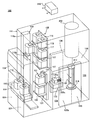
도 1은 본 발명에 적용되는 기판 처리 장치의 사투시도.
도 2는 본 발명이 적용되는 기판 처리 장치를 도시하는 투시 측면도.
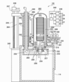
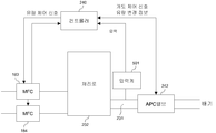
도 3은 본 발명이 적용되는 기판 처리 장치의 처리로 및 처리로 주변의 개략 구성도.
도 4a는 본 발명에 따른 기판 처리 공정을 도시한 플로우 차트.
도 4b는 압력 제어 공정을 상세하게 도시한 플로우 차트.
도 4c는 본 발명에 적용되는 기판 처리 장치의 처리로 내의 압력의 설정값과 측정값을 비교한 그래프.
도 5는 본 발명에 적용되는 기판 처리 장치 주변의 구성을 간략하게 도시한 도면.
도 6은 본 발명에 적용되는 기판 처리 장치의 처리로 내의 시간 변화에 따른 압력 변화를 도시한 그래프.
도 7은 본 발명의 제2 실시 형태에 적용되는 기판 처리 장치의 일 예를 도시하는 개략도.
도 8은 본 발명의 제2 실시 형태에 적용되는 기판 처리 장치 주변의 구성을 간략하게 도시한 도면.
도 9는 본 발명의 제2 실시 형태에 적용되는 기판 처리 장치의 처리로 내의 압력의 설정값과 측정값을 비교한 그래프.1 is a perspective view of a substrate processing apparatus applied to the present invention.
2 is a perspective side view showing a substrate processing apparatus to which the present invention is applied.
3 is a schematic configuration diagram of a process furnace and a process furnace periphery of the substrate processing apparatus to which the present invention is applied.
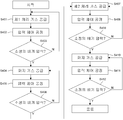
4A is a flow chart illustrating a substrate processing process in accordance with the present invention.
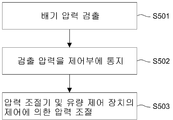
4B is a flow chart illustrating in detail the pressure control process.
Fig. 4C is a graph comparing the set value and the measured value of the pressure in the processing furnace of the substrate processing apparatus applied to the present invention.
5 is a diagram schematically showing a configuration around a substrate processing apparatus applied to the present invention.
6 is a graph showing a change in pressure with a change in time in a processing furnace of a substrate processing apparatus applied to the present invention.
7 is a schematic diagram illustrating an example of a substrate processing apparatus applied to a second embodiment of the present invention.
FIG. 8 is a diagram schematically showing a configuration around a substrate processing apparatus applied to a second embodiment of the present invention. FIG.
9 is a graph in which a set value and a measured value of pressure in a processing furnace of a substrate processing apparatus applied to a second embodiment of the present invention are compared.
<발명자들이 얻은 지견>Knowledge gained by inventors
발명자들은 연구를 거듭한 결과, 아래와 같은 문제점을 발견하였다. 처리실 내의 기판에 대하여 제1 원료 가스를 공급하는 공정, 제1 원료 가스의 공급을 정지한 상태에서 처리실 내에 잔류하는 제1 원료 가스를 배기 라인에 의해 배기하는 공정, 처리실 내의 기판에 대하여 제2 원료 가스를 공급하는 공정 및 제2 원료 가스의 공급을 정지한 상태에서 처리실 내에 잔류하는 제2 원료 가스를 배기 라인에 의해 배기하는 공정을 소정 횟수 반복하는 것에 의하여 기판 상에 박막을 형성하는 처리를 수행하는 기판 처리 방법에서는 스루풋 향상을 목적으로 하여 원료 가스를 공급하거나 배기하는 것에 의해 처리실 내를 신속하게 소정의 압력으로 조절할 필요가 있다. 처리 대상이 되는 기판이 대구경화하면, 처리실 내의 용적이 증대하고 공급하는 가스 유량도 증가한다. 따라서, 가스 공급의 유량을 제어하는 매스 플로우 컨트롤러(MFC)를 이용하여 처리실 내의 압력을 일정하게 하기 위해서 유량 조절을 할 때에, 유량 조절의 타이밍이 지나치게 느리면 오버슈트가 발생하고, 타이밍이 지나치게 빠르면 언더슈트가 발생하기 쉬워진다.The inventors have conducted the following studies and found the following problems. Supplying the first raw material gas to the substrate in the processing chamber; exhausting the first raw material gas remaining in the processing chamber by the exhaust line with the supply of the first raw material gas stopped; and supplying the second raw material to the substrate in the processing chamber. A process of forming a thin film on the substrate is performed by repeating a process of supplying a gas and a process of exhausting the second source gas remaining in the process chamber by the exhaust line while the supply of the second source gas is stopped a predetermined number of times. In the substrate processing method described above, it is necessary to quickly adjust the inside of the processing chamber to a predetermined pressure by supplying or exhausting source gas for the purpose of throughput improvement. When the substrate to be processed is largely cured, the volume in the processing chamber increases and the gas flow rate supplied increases. Therefore, when adjusting the flow rate in order to make the pressure in the process chamber constant by using a mass flow controller (MFC) that controls the flow rate of the gas supply, an overshoot occurs if the timing of the flow adjustment is too slow, and if the timing is too fast, the undershoot occurs. A chute tends to occur.
본 발명은 본 발명자들이 발견한 상기 지견에 기초한다.The present invention is based on the above findings found by the present inventors.
<제1 실시 형태>≪ First Embodiment >
다음으로 본 발명의 실시 형태를 도면에 기초하여 설명한다. 본 발명이 적용되는 실시 형태에서 기판 처리 장치는 일 예로서 반도체 장치(IC)의 제조 방법에서의 처리 장치를 실시하는 반도체 제조 장치로서 구성된다. 또한 이하의 설명에서는 기판 처리 장치로서 기판에 산화, 확산 처리 등을 수행하는 종형의 장치(이하, 단순히 처리 장치라고 부른다)를 적용한 경우에 대하여 설명한다. 도 1은 본 발명이 적용되는 기판 처리 장치의 사시도로서 도시된다. 또한 도 2는 도 1에 도시하는 기판 처리 장치의 측면 투시도다.EMBODIMENT OF THE INVENTION Next, embodiment of this invention is described based on drawing. In the embodiment to which the present invention is applied, the substrate processing apparatus is configured as a semiconductor manufacturing apparatus that performs the processing apparatus in the manufacturing method of the semiconductor device (IC) as an example. In addition, the following description demonstrates the case where the vertical type apparatus (henceforth simply a processing apparatus) is applied to a board | substrate as an substrate processing apparatus which performs oxidation, a diffusion process, etc .. 1 is a perspective view of a substrate processing apparatus to which the present invention is applied. 2 is a side perspective view of the substrate processing apparatus shown in FIG.
도 1 및 도 2에 도시되는 바와 같이 실리콘 등으로 이루어지는 복수의 웨이퍼(200)(기판)를 수용하고, 수용 용기로서 이용되는 웨이퍼 캐리어로서 후프(110)(이하 포드라고 부른다)가 사용되는 기판 처리 장치(100)는 기판 처리 장치 본체로서 이용되는 광체(筐體)(111)를 구비한다.1 and 2, a substrate processing in which a plurality of wafers 200 (substrates) made of silicon or the like are accommodated and a hoop 110 (hereinafter referred to as a pod) is used as a wafer carrier used as a storage container. The
광체(111)의 정면 벽(111a)의 정면 전방부에는 메인터넌스 가능하도록 설치된 개구부로서의 정면 메인터넌스구(口)(103)가 개설되고, 이 정면 메인터넌스구(103)를 개폐하는 정면 메인터넌스 도어(104)가 각각 설치된다. 광체(111)의 정면 벽(111a)에는 포드 반입 반출구(112)가 광체(111)의 내외를 연통하도록 개설되고, 포드 반입 반출구(112)는 프론트 셔터(113)에 의해 개폐되도록 이루어진다. 포드 반입 반출구(112)의 정면 전방측에는 반입 반출부로서 이용되는 로드 포트(114)가 설치되고, 로드 포트(114)는 포드(110)를 재치하여 위치를 맞추도록 구성된다. 포드(110)는 로드 포트(114) 상에 공정 내 반송 장치(도시되지 않음)에 의해 반입되고, 또한 로드 포트(114) 상으로부터 반출되도록 이루어진다.In the front front part of the
광체(111) 내의 전후 방향의 대략 중앙부에서의 상부에는 포드 선반(105)(수용 선반)이 설치된다. 포드 선반(105)은 수직으로 설치되는 지지부(116)와, 지지부(116)에 대하여 예컨대 상중하단의 각 위치에서 수직 방향으로 각각 독립해서 이동 가능하도록 보지된 복수 단의 재치부(117)를 구비하고, 포드 선반(105)은 복수 단의 재치부(117)에 포드(110)를 복수 개 각각 재치한 상태에서 보지하도록 구성된다. 즉 포드 선반(105)은 예컨대 2개의 포드(110)를 일직선 상에 동일 방향을 향해서 배치하여 수직 방향에 복수 단으로 복수 개의 포드(110)를 수용한다.The pod shelf 105 (receiving shelf) is provided in the upper part in the substantially center part of the front-back direction in the
광체(111) 내에서의 로드 포트(114)와 포드 선반(105) 사이에는 포드 반송 장치(118)(수용 용기 반송 기구)가 설치된다. 포드 반송 장치(118)는 포드(110)를 보지한 상태에서 수직 방향으로 승강 가능한 축부로서의 포드 엘리베이터(118a)와, 포드(110)를 재치하여 수평 방향으로 반송하는 반송부로서의 포드 반송부(118b)로 구성되고, 포드 반송 장치(118)는 포드 엘리베이터(118a)와 포드 반송부(118b)의 연속 동작에 의해 로드 포트(114), 포드 선반(105), 포드 오프너(121) 사이에서 포드(110)를 반송하도록 구성된다.A pod carrying device 118 (a container carrying mechanism) is provided between the
광체(111) 내의 전후 방향의 대략 중앙부에서의 하부에는 서브 광체(119)가 후단에 걸쳐 구축된다. 서브 광체(119)의 정면 벽(119a)에는 웨이퍼(200)를 서브 광체(119) 내에 대하여 반입 반출하기 위한 웨이퍼 반입 반출구(120)가 한 쌍, 예컨대 수직 방향으로 상하 2단으로 배열하여 개설되고, 상하단의 웨이퍼 반입 반출구(120)에는 한 쌍의 포드 오프너(121)가 각각 설치된다. 포드 오프너(121)는 포드(110)를 재치하는 재치대(122)와, 밀폐 부재로서 이용되는 포드(110)의 캡을 탈착하는 캡 탈착 기구(123)를 구비한다. 포드 오프너(121)는 재치대(122)에 재치된 포드(110)의 캡을 캡 탈착 기구(123)에 의해 탈착하는 것에 의해 포드(110)의 웨이퍼 출입구를 개폐하도록 구성된다.The
서브 광체(119)는 포드 반송 장치(118)나 포드 선반(105)의 설치 공간으로부터 유체적으로 격리된 이재실(124)을 구성한다. 이재실(124) 앞쪽 영역에는 웨이퍼 이재 기구(125)가 설치되고, 웨이퍼 이재 기구(125)는 웨이퍼(200)를 수평 방향으로 회전 또는 직동 가능한 웨이퍼 이재 장치(125a) 및 웨이퍼 이재 장치(125a)를 승강시키기 위한 웨이퍼 이재 장치 엘리베이터(125b)로 구성된다. 도 1에 모식적으로 도시되는 바와 같이 웨이퍼 이재 장치 엘리베이터(125b)는 내압(耐壓) 광체(111) 우측 단부와 서브 광체(119)의 이재실(124) 전방 영역 우단부 사이에 설치된다. 이 웨이퍼 이재 장치 엘리베이터(125b) 및 웨이퍼 이재 장치(125a)의 연속 동작에 의해 웨이퍼 이재 장치(125a)의 트위저(125c)(기판 보지체)를 웨이퍼(200)의 재치부로서 보트(217)(기판 보지구)에 대하여 웨이퍼(200)를 장전(charging) 및 탈장(discharging)하도록 구성된다.The
이재실(124)의 후측 영역에는 보트(217)를 수용하여 대기시키는 대기부(126)가 구성된다. 대기부(126)의 상방에는 처리실로서 이용되는 처리로(202)가 설치된다. 처리로(202)의 하단부는 노구(爐口) 셔터(147)에 의해 개폐되도록 구성된다. 또한 도시하지 않지만, 웨이퍼 처리 조건 등에 의해 산소 농도를 낮추는 경우 등 필요에 따라 처리로(202) 바로 아래의 대기부(126)를 둘러싸도록 예비실(로드록 실)을 설치하고, 미리 산소 농도를 저하시키거나, 기판 처리된 웨이퍼의 냉각 등을 수행해도 좋다.In the rear region of the
도 1에 모식적으로 도시되는 바와 같이, 내압 광체(111) 우측 단부와 서브 광체(119)의 대기부(126) 우단부 사이에는 보트(217)를 승강시키기 위한 보트 엘리베이터(115)가 설치된다. 보트 엘리베이터(115)의 승강대에 연결된 연결구로서의 암(128)에는 개체(蓋體)로서의 씰 캡(219)이 수평으로 설치되고, 씰 캡(219)은 보트(217)를 수직으로 지지하여 처리로(202)의 하단부를 폐색 가능하도록 구성된다. 보트(217)는 복수 개의 보지 부재를 구비하고, 복수 매(예컨대 25∼200매 정도)의 웨이퍼(200)를 그 중심을 맞춰서 수직 방향으로 정렬시킨 상태에서 각각 수평하게 보지하도록 구성된다.As schematically shown in FIG. 1, a
도 1에 모식적으로 도시되는 바와 같이, 이재실(124)의 웨이퍼 이재 장치 엘리베이터(125b) 측 및 보트 엘리베이터(115) 측과 반대측인 좌측 단부에는 청정화된 분위기 또는 불활성 가스인 클린 에어(133)을 공급하도록 공급 팬 및 방진 필터로 구성된 클린 유닛(134)이 설치되고, 웨이퍼 이재 장치(125a)와 클린 유닛(134) 사이에는, 웨이퍼의 원주 방향의 위치를 조정시키는 기판 정합 장치로서의 노치(notch) 맞춤 장치(미도시)가 설치된다. 클린 유닛(134)으로부터 유출된 클린 에어(133)는 노치 맞춤 장치(미도시) 및 웨이퍼 이재 장치(125a), 대기부(126)에 있는 보트(217)에 유통된 후, 도시되지 않는 덕트에 의해 흡입되고 광체(111)의 외부에 배기가 이루어지거나, 또는 클린 유닛(134)의 흡입측인 일차측(공급측)까지 순환되고 다시 클린 유닛(134)에 의해 이재실(124) 내에 유출되도록 구성된다.As schematically shown in FIG. 1,
다음으로 기판 처리 장치(100)의 동작에 대하여 설명한다. 또한 이하의 설명에서 기판 처리 장치(100)를 구성하는 각(各) 부(部)의 동작은 컨트롤러(240)에 의해 제어된다. 도 3에는 상기 기판 처리 장치(100)의 처리로(202) 및 처리로(202) 주변의 개략 구성도이며, 종단면도가 도시된다. 컨트롤러(240) 내의 온도 제어부(238), 가스 유량 제어부(235), 압력 제어부(236), 구동 제어부(237) 각각은 조작부(미도시) 및 입출력부(미도시)를 포함하고, 기판 처리 장치(100) 전체를 제어하는 주(主)제어부(239)에 전기적으로 접속된다. 가스 유량 제어부(235), 압력 제어부(236), 구동 제어부(237), 온도 제어부(238), 주제어부(239)는 컨트롤러(240)로서 구성된다. 예컨대 컨트롤러(240)는 구동 제어부(241)에 의하여 포드 반송 장치(118), 포드 선반(105), 웨이퍼 이재 기구(125), 보트 엘리베이터(115) 등을 제어한다.Next, the operation of the
도 1 및 도 2에 도시되는 바와 같이 포드(110)가 로드 포트(114)에 공급되면, 포드 반입 반출구(112)가 프론트 셔터(113)에 의해 개방되고, 로드 포트(114) 상의 포드(110)는 포드 반송 장치(118)에 의해 광체(111)의 내부로 포드 반입 반출구(112)로부터 반입된다. 반입된 포드(110)는 포드 선반(105)이 지정된 재치부(117)로 포드 반송 장치(118)에 의해 자동적으로 반송되고 일시적으로 보관된 후, 포드 선반(105)으로부터 일방의 포드 오프너(121)에 반송되어서 재치대(122)에 이재되거나, 또는 직접 포드 오프너(121)에 반송되어서 재치대(122)에 이재된다. 이 때 포드 오프너(121)의 웨이퍼 반입 반출구(120)는 캡 탈착 기구(123)에 의해 폐색되고, 이재실(124)에는 클린 에어(133)가 유통되어서 충만된다. 예컨대 이재실(124)에는 클린 에어(133)로서 질소 가스가 충전되는 것에 의해 산소 농도가 20ppm 이하와, 광체(111)의 내부[대기(大氣) 분위기]의 산소 농도보다 훨씬 낮게 설정된다.As shown in FIGS. 1 and 2, when the
재치대(122)에 재치된 포드(110)는 그 개구측 단면이 서브 광체(119)의 정면 벽(119a)에서의 웨이퍼 반입 반출구(120)의 개구 연변부(緣邊部)에 밀어붙여지는 것과 함께, 그 캡이 캡 탈착 기구(123)에 의해 제거되어 웨이퍼 출입구가 개방된다. 포드(110)가 포드 오프너(121)에 의해 개방되면, 웨이퍼(200)는 포드(110)로부터 웨이퍼 이재 장치(125a)의 트위저(125c)에 의해 웨이퍼 출입구를 통해서 픽업되고, 도시되지 않는 노치 맞춤 장치(미도시)로 웨이퍼를 조정한 후, 이재실(124)의 후방에 있는 대기부(126)로 반입되어 보트(217)에 장전(charging)된다. 보트(217)에 웨이퍼(200)를 수도한 웨이퍼 이재 장치(125a)는 포드(110)에 돌아가 다음 웨이퍼(200)를 보트(217)에 장전한다.In the
이 일방(상단 또는 하단)의 포드 오프너(121)에서의 웨이퍼 이재 기구(125)에 의한 웨이퍼의 보트(217)로의 장전 작업 중에 타방(하단 또는 상단)의 포드 오프너(121)에는 포드 선반(105)으로부터 다른 포드(110)가 포드 반송 장치(118)에 의해 반송되어 이재되고, 포드 오프너(121)에 의한 포드(110)의 개방 작업이 동시에 진행된다.The
미리 지정된 매수의 웨이퍼(200)가 보트(217)에 장전되면, 노구 셔터(147)에 의해 닫쳐진 처리로(202)의 하단부가 노구 셔터(147)에 의해 개방된다. 계속해서 웨이퍼(200)군(群)을 보지한 보트(217)는 씰 캡(219)이 보트 엘리베이터(115)에 의해 상승되는 것에 의해 처리로(202) 내에 반입(로딩)된다.When a predetermined number of
로딩 후에는 처리로(202)에서 웨이퍼(200)에 임의의 처리가 실시된다. 처리 후는 노치 맞춤 장치(미도시)에서의 웨이퍼의 정합 공정을 제외하면 대략 전술한 것과 반대의 순서로 웨이퍼(200) 및 포드(110)는 광체의 외부로 불출(拂出)된다.After loading, the
다음으로 상기 기판 처리 장치(100)의 처리로(202) 및 처리로(202) 주변의 구성에 대하여 설명한다. 도 3에 도시되는 바와 같이 처리로(202)는 가열 기구로서의 히터(206)를 포함한다. 히터(206)는 원통 형상이며, 히터 소선(素線)과 그 주위에 설치된 단열 부재로 구성되고, 도시되지 않는 보지체에 지지되는 것에 의해 수직으로 설치된다.Next, the structure around the
히터(206)의 내측에는 히터(206)와 동심원 형상으로 반응관으로서의 아우터 튜브(205)가 배설(配設)된다. 아우터 튜브(205)는 석영(SiO2) 또는 탄화실리콘(SiC) 등의 내열 재료로 이루어지고, 상단이 폐색되고 하단이 개구된 원통 형상으로 형성된다. 아우터 튜브(205)의 내측의 통중공부(筒中空部)에는 처리실(201)이 형성되고, 기판으로서의 웨이퍼(200)를 상기 보트(217)에 의해 수평 자세로 수직 방향에 다단으로 정렬한 상태에서 수용 가능하도록 구성된다.Inside the
아우터 튜브(205)의 하방에는 아우터 튜브(205)와 동심원 형상으로 매니폴드(209)가 배설된다. 매니폴드(209)는 예컨대 스텐레스 등으로 이루어지고, 상단 및 하단이 개구된 원통 형상으로 형성된다. 이 매니폴드(209)는 아우터 튜브(205)를 지지하도록 설치된다. 또한 매니폴드(209)와 아우터 튜브(205) 사이에는 씰 부재로서의 O링(309)이 설치된다. 이 매니폴드(209)가 도시되지 않는 보지체에 지지되는 것에 의해 아우터 튜브(205)는 수직으로 설치된 상태가 된다. 이와 같이 아우터 튜브(205)와 매니폴드(209)에 의해 반응 용기가 형성된다.Below the
매니폴드(209)에는 가스 배기관(231)이 설치되는 것과 함께 가스 공급관(232)(가스 공급 노즐)이 관통하도록 설치된다. 가스 공급관(232)은 처리로(202)의 내벽과 웨이퍼(200) 사이에서의 원호 형상의 공간에 처리로(202)의 내벽 하부로부터 상부를 따라 웨이퍼(200)의 적재 방향 상방을 향해서 상승하도록 설치되고, 또한 상류측에서 예컨대 3개로 나뉘어지고, 밸브(177, 178, 179)와 가스 유량 제어 장치로서의 MFC(183, 184, 185)를 개재하여 제1 가스 공급원(180), 제2 가스 공급원(181), 제3 가스 공급원(182)에 각각 접속된다. MFC(183, 184, 185) 및 밸브(177, 178, 179)에는 가스 유량 제어부(235)가 전기적으로 접속되고, MFC(183, 184, 185)는 공급되는 가스의 유량이 원하는 유량이 되도록 원하는 타이밍에 제어하도록 구성된다.The manifold 209 is provided so that the
또한 본 실시 형태에서는 전술한 바와 같이 가스 공급관(232)이 상류측에서 3개로 나뉘는 형상으로 설명하였지만, 본 발명은 이에 한정되지 않고, 가스 공급원마다 개별로 설치되어도 좋고, 또한 길이가 다른 가스 공급관을 각각 기판 처리의 보지 영역에 맞춰서 설치해도 좋고, 이들을 조합시켜도 좋다. 또한 가스 공급관에 설치되는 가스 공급을 위한 가스 공급공은 웨이퍼의 적재 간격과 동일한 간격으로 가스 공급공이 설치될 수 있는 다공 노즐이어도 좋고, 가스 공급을 균일하게 하기 위한 버퍼실을 설치해도 좋다.In the present embodiment, as described above, the
가스 배기관(231)의 하류측에는 압력 검출기로서의 압력계(압력 센서) 및 압력 조절기로서의 APC 밸브(242)를 개재하여 진공 펌프 등의 진공 배기 장치(246)가 접속된다. 압력계 및 APC 밸브(242)에는 압력 제어부(236)가 전기적으로 접속되고, 압력 제어부(236)는 압력계에 의해 검출된 압력값에 기초하여 APC 밸브(242)의 개도(開度)를 조절하는 것에 의해 처리실(201) 내의 압력이 원하는 압력이 되도록 원하는 타이밍에 제어하도록 구성된다.On the downstream side of the
매니폴드(209)의 하방에는 매니폴드(209)의 하단 개구를 기밀하게 폐색하기 위한 노구 개체로서 씰 캡(219)이 설치된다. 씰 캡(219)은 예컨대 스텐레스 등의 금속을 재료로 하여 원반 형상으로 형성된다. 씰 캡(219)의 상면에는 매니폴드(209)의 하단에 당접하는 씰 부재로서의 O링(301)이 설치된다. 씰 캡(219)에는 회전 기구(254)가 설치된다. 회전 기구(254)의 회전축(255)은 씰 캡(219)을 관통하여 상기 보트(217)에 접속되고, 보트(217)를 회전시키는 것에 의해 웨이퍼(200)를 회전시키도록 구성된다. 씰 캡(219)은 처리로(202)의 외측에 설치된 승강 기구로서의 후술하는 승강 모터(248)에 의해 수직 방향으로 승강되도록 구성되고, 이에 의해 보트(217)를 처리실(201)에 대하여 반입 반출하는 것이 가능하도록 이루어진다. 회전 기구(254) 및 승강 모터(248)에는 구동 제어부(237)가 전기적으로 접속되고, 원하는 동작을 하도록 원하는 타이밍에 제어하도록 구성된다.Below the manifold 209, a
히터(206) 근방에는 처리실(201) 내의 온도를 검출하는 온도 검출부로서의 온도 센서(도시되지 않음)가 설치된다. 히터(206) 및 온도 센서에는 전기적으로 온도 제어부(238)가 접속되고, 온도 센서에 의해 검출된 온도 정보에 기초하여 히터(206)로의 통전 상태를 조절하는 것에 의해 처리실(201) 내의 온도가 원하는 온도 분포가 되도록 원하는 타이밍에 제어하도록 구성된다.In the vicinity of the
이 처리로(202)의 구성에서 제1 처리 가스는 제1 가스 공급원(180)으로부터 공급되고 MFC(183)에 의하여 그 유량이 조절된 후, 밸브(177)를 개재하여 가스 공급관(232)에 의해 처리실(201) 내에 공급된다. 또한 제2 처리 가스는 제2 가스 공급원(181)으로부터 공급되고 MFC(184)에 의하여 그 유량이 조절된 후, 밸브(178)를 개재하여 가스 공급관(232)에 의해 처리실(201) 내에 공급된다. 제3 처리 가스는 제3 가스 공급원(182)으로부터 공급되고 MFC(185)에 의하여 그 유량이 조절된 후, 밸브(179)를 개재하여 가스 공급관(232)에 의해 처리실(201) 내에 공급된다. 또한 처리실(201) 내의 가스는 가스 배기관(231)에 접속된 진공 배기 장치(246)로서의 진공 펌프에 의해 처리실(201)로부터 배기된다.In the configuration of the
상기 서브 광체(119)의 외면에 하기판(下基板)(245)이 설치된다. 하기판(245)에는 승강대(249)와 결합하는 가이드 샤프트(264) 및 승강대(249)에 체결되는 볼 나사(244)가 설치된다. 하기판(245)에 설치된 가이드 샤프트(264) 및 볼 나사(244)의 상단에 상기판(上基板)(247)이 설치된다. 볼 나사(244)는 상기판(247)에 설치된 승강 모터(248)에 의해 회전된다. 볼 나사(244)가 회전하는 것에 의해 승강대(249)가 승강하도록 구성된다.A
승강대(249)에는 중공의 승강 샤프트(250)가 수직으로 설치되고, 승강대(249)와 승강 샤프트(250)의 연결부는 기밀(氣密)하게 이루어진다. 승강 샤프트(250)는 승강대(249)와 함께 승강되도록 이루어진다. 승강 샤프트(250)는 서브 광체(119)의 천정판(251)을 관통한다. 승강 샤프트(250)가 관통하는 천정판(251)의 관통공은 승강 샤프트(250)에 대하여 접촉하지 않도록 충분한 여유가 있다. 서브 광체(119)와 승강대(249) 사이에는 승강 샤프트(250)의 주위를 피복하도록 신축성을 가지는 중공 신축체로서의 벨로즈(265)가 서브 광체(119)를 기밀하게 유지하기 위해서 설치된다. 벨로즈(265)는 승강대(249)의 승강량에 대응할 수 있는 충분한 신축량을 가지고, 벨로즈(265)의 내경은 승강 샤프트(250)의 외형에 비해 충분히 커서 벨로즈(265)의 신축으로 접촉하지 않도록 구성된다.A
승강 샤프트(250)의 하단에는 승강 기판(252)이 수평하게 고착된다. 승강 기판(252)의 하면에는 O링 등의 씰 부재를 개재하여 구동부 커버(253)가 기밀하게 설치된다. 승강 기판(252)과 구동부 커버(253)로 구동부 수납 케이스(256)가 구성된다. 이 구성에 의해 구동부 수납 케이스(256) 내부는 서브 광체(119) 내의 분위기와 격리된다.The lifting
또한 구동부 수납 케이스(256)의 내부에는 보트(217)의 회전 기구(254)가 설치되고, 회전 기구(254)의 주변은 냉각 기구(257)에 의해 냉각된다.Moreover, the
전력 공급 케이블(258)이 승강 샤프트(250)의 상단으로부터 승강 샤프트(250)의 중공부를 지나서 회전 기구(254)에 인도되어 접속된다. 또한 냉각 기구(257), 씰 캡(219)에는 냉각 유로(259)가 형성되고, 냉각 유로(259)에는 냉각수를 공급하는 냉각수 배관(260)이 접속되고, 승강 샤프트(250)의 상단으로부터 승강 샤프트(250)의 중공부를 통과한다.The
승강 모터(248)가 구동되어 볼 나사(244)가 회전하는 것에 의해 승강대(249) 및 승강 샤프트(250)를 개재하여 구동부 수납 케이스(256)가 승강한다.As the lifting
구동부 수납 케이스(256)가 상승하는 것에 의해 승강 기판(252)에 기밀하게 설치되는 씰 캡(219)이 처리로(202)의 개구부인 노구(161)를 폐색하여 웨이퍼 처리가 가능한 상태가 된다. 구동부 수납 케이스(256)가 하강되는 것에 의해 씰 캡(219)과 함께 보트(217)가 강하되어 웨이퍼(200)를 외부에 반출할 수 있는 상태가 된다.As the driving
가스 유량 제어부(235), 압력 제어부(236), 구동 제어부(237), 온도 제어부(238) 각각은 조작부 및 입출력부를 포함하고, 기판 처리 장치(100) 전체를 제어하는 주제어부(239)에 전기적으로 접속된다. 이 가스 유량 제어부(235), 압력 제어부(236), 구동 제어부(237), 온도 제어부(238), 주제어부(239)는 컨트롤러(240)를 구성한다.Each of the gas flow
(기판 처리 공정)(Substrate processing step)
다음으로, 기판 처리 장치(100)를 이용하여 웨이퍼(200) 상에 소정의 막을 형성하는 기판 처리 공정에 대하여 도 3 및 도 4a~4c를 이용하여 설명한다. 도 4a는 본 발명에 따른 기판 처리 공정을 도시한 플로우 차트이고, 도 4b는 압력 제어 공정을 상세하게 도시한 플로우 차트이다. 도 4c는 본 발명에 적용되는 기판 처리 장치의 처리로 내의 압력 설정값과 압력 측정값을 비교한 그래프다.Next, the substrate processing process of forming a predetermined film on the
여기서 본 실시 형태에서는 제1 가스 공급원(180)으로부터 공급되는 가스를 제1 막 형성을 위한 제1 원료 가스(제1 처리 가스)라고 하고, 제2 가스 공급원(181)으로부터 공급되는 가스를 제2 막 형성을 위한 제2 원료 가스(제2 처리 가스)라고 하고, 제3 가스 공급원(182)으로부터 공급되는 가스를 처리로 내의 분위기를 퍼지(purge)하기 위한 퍼지 가스로 하여 기판 처리 공정에 대하여 설명한다. 그러나, 본 발명은 이에 한정되지 않고, 예컨대 제2 가스 공급원(181)으로부터는 캐리어 가스로서의 불활성 가스를 공급해도 좋고, 가스 공급원을 늘려서 에칭을 위한 에칭 가스를 공급해도 좋다.In this embodiment, the gas supplied from the first gas supply source 180 is referred to as a first source gas (first processing gas) for forming the first film, and the gas supplied from the second gas supply source 181 is referred to as a second gas. The substrate processing process will be described as a second source gas (second process gas) for film formation, and a gas supplied from the third gas supply source 182 as a purge gas for purging the atmosphere in the processing furnace. do. However, this invention is not limited to this, For example, the inert gas as a carrier gas may be supplied from the 2nd gas supply source 181, The gas supply source may be extended, and the etching gas for etching may be supplied.
또한 본 실시 형태에서의 가스 공급원으로부터 공급되는 처리 가스의 구체 예로서는 예컨대 실리콘 원자를 함유하는 실리콘 함유 가스(SiH4, Si2H6, Si3H8, SiCl4, Si2Cl6, SiHCl3, SiH2Cl2)나, 게르마늄 원자를 포함하는 게르마늄 함유 가스(GeH4, GeCl4), 탄소 원자를 함유하는 탄소 원자 함유 가스(C3H8,), 탄소 원소와 질소 원소를 포함하는 아민계 가스(에틸아민, 트리에틸아민, 메틸아민, 프로필아민, 이소프로필아민, 부틸아민, 이소부틸아민 등의 아민을 포함한다) 등이 있다. 마찬가지로 본 실시 형태에서의 가스 공급원으로부터 공급되는 불활성 가스로서는 질소(N2) 가스 외에 Ar가스, He가스, Ne가스, Xe가스 등의 희가스 등이 있다. 또한 클리닝 가스로서는 염소 원자를 함유하는 염소 함유 가스나, 불소 원자를 함유하는 불소 함유 가스 등이 있고, 예컨대 염소 가스(Cl2), 염화수소(HCl), ClF3 등을 들 수 있다.In addition, a concrete example a silicon-containing gas containing a silicon atom (SiH 4, Si 2 H 6 , Si 3 H 8, SiCl 4, Si 2 Cl 6, SiHCl of the process gas supplied from the gas supply source in the third embodiment, SiH 2 Cl 2 ), germanium containing gas containing germanium atoms (GeH 4 , GeCl 4 ), carbon atom containing gas containing carbon atoms (C 3 H 8 ,), amine system containing carbon and nitrogen elements Gases (including amines such as ethylamine, triethylamine, methylamine, propylamine, isopropylamine, butylamine, isobutylamine), and the like. Similarly, inert gas supplied from the gas supply source in the present embodiment includes rare gas such as Ar gas, He gas, Ne gas, and Xe gas, in addition to nitrogen (N 2 ) gas. Examples of the cleaning gas include chlorine-containing gas containing chlorine atoms, fluorine-containing gas containing fluorine atoms, and the like, and examples thereof include chlorine gas (Cl 2 ), hydrogen chloride (HCl), and ClF 3 .
미리 설정된 매수의 웨이퍼(200)를 보지한 보트(217)가 처리로(202) 내로 로딩되면, 온도 제어부(238)의 제어에 따라 히터(206)가 처리로(202) 내를 소정의 기판 처리 온도까지 승온한다.When the
처리로(202) 내가 소정의 기판 처리 온도까지 승온되면, 제1 가스 공급원(180)으로부터 제1 원료 가스가 가스 유량 제어부(235)의 제어에 따라 MFC(183)에 의해 유량이 조절되면서 밸브(177)를 개재하여 처리로(202) 내가 설정된 압력으로 될 때까지 소정 시간을 들여서 공급된다(S401~S403).When the inside of the
먼저, 제1 처리 가스를 공급하고(S401), 압력 제어 공정을 수행한다(S402). 그 다음에, 배기 압력이 소정의 압력인지 확인한다(S403). S403 단계에서 배기 압력이 소정의 압력이 아니면 S401 단계로 되돌아간다. 그러나, S403 단계에서 배기 압력이 소정의 압력이면 S404 단계로 진행한다.First, a first processing gas is supplied (S401), and a pressure control process is performed (S402). Next, it is checked whether the exhaust pressure is a predetermined pressure (S403). If the exhaust pressure is not the predetermined pressure in step S403, the process returns to step S401. However, if the exhaust pressure is a predetermined pressure in step S403, the process proceeds to step S404.
도 4b를 참조하면, 압력 제어 공정에서는 배기 압력을 검출하고(S501), 검출된 배기 압력을 나타내는 신호를 제어부에 송신하고(S502), 압력 조절기 및 유량 제어 장치를 제어하여 압력을 조절한다(S503).Referring to FIG. 4B, in the pressure control process, the exhaust pressure is detected (S501), a signal indicating the detected exhaust pressure is transmitted to the control unit (S502), and the pressure regulator and the flow control device are controlled to adjust the pressure (S503). ).
제1 원료 가스 공급에 의해 처리로(202) 내의 압력이 설정한 압력이 되면, 밸브(177)를 닫아 제1 원료 가스의 공급을 정지하고, 제3 가스 공급원(182)으로부터 퍼지 가스를 공급한다(S404). 그리고, 도 4b에 도시된 압력 제어 공정을 수행하고(S405), 배기 압력이 소정의 압력인지 확인한다(S406). S406 단계에서 배기 압력이 소정의 압력이 아니면 S404 단계로 되돌아가고, 배기 압력이 소정의 압력이면 S407 단계로 진행한다. S404~S406 단계에서는, MFC(185)에 의하여 그 유량이 조절된 후, 밸브(179)를 개재하여 퍼지 가스가 공급된다. 이와 함께, 압력 제어부(236)의 제어에 따라 APC 밸브(242)에 의해 배기량을 조절하면서 처리로(202) 내에 잔류하는 제1 원료 가스를 소정 시간 퍼지한다.When the pressure in the
제1 원료 가스를 소정 시간 퍼지한 후, 밸브(179)를 닫아 퍼지 가스의 공급을 정지하고, 제2 가스 공급원(181)으로부터 제2 원료 가스가 가스 유량 제어부(235)의 제어에 따라 MFC(184)에 의해 유량이 조절되면서 밸브(178)를 개재하여 처리로(202) 내가 설정된 압력이 될 때까지 소정 시간을 들여서 공급된다(S407~S409).After purging the first raw material gas for a predetermined time, the
먼저, 제2 처리 가스를 공급하고(S407), 도 4b에 도시된 압력 제어 공정을 수행한다(S408). 그 다음에, 배기 압력이 소정의 압력인지 확인한다(S409). S409 단계에서 배기 압력이 소정의 압력이 아니면 S407 단계로 되돌아간다. 그러나, S409 단계에서 배기 압력이 소정의 압력이면 S410 단계로 진행한다.First, a second processing gas is supplied (S407), and a pressure control process shown in FIG. 4B is performed (S408). Next, it is checked whether the exhaust pressure is a predetermined pressure (S409). If the exhaust pressure is not the predetermined pressure in step S409, the flow returns to step S407. However, if the exhaust pressure is a predetermined pressure in step S409, the flow proceeds to step S410.
제2 원료 가스의 공급에 의해 처리로(202) 내가 설정된 압력이 되면, 밸브(178)를 닫아 제2 원료 가스의 공급을 정지하고, 제3 가스 공급원(182)으로부터 퍼지 가스가 MFC(185)에 의하여 그 유량이 조절되면서 밸브(179)를 개재하여 공급된다(S410). 그리고, 도 4b에 도시된 압력 제어 공정을 수행하고(S411), 배기 압력이 소정의 압력인지 확인한다(S412). S412 단계에서 배기 압력이 소정의 압력이 아니면 S410 단계로 되돌아가고, 배기 압력이 소정의 압력이면 퍼지 가스의 공급을 종료한다. S410~S412 단계에서는, 압력 제어부(236)의 제어에 따라 APC 밸브(242)에 의해 배기량을 조절하면서 처리로(202) 내에 잔류하는 제2 원료 가스를 소정 시간 퍼지한다.When the pressure inside the
이상의 공정(S401∼S412)을 연속적으로 수행하는 사이클을 소정 횟수 반복하는 것에 의해, 원하는 두께를 갖는 막을 웨이퍼(200) 상에 형성한다. 또한 필요에 따라 에칭(클리닝) 가스를 공급해도 좋다.By repeating the cycle of performing the above processes S401 to S412 a predetermined number of times, a film having a desired thickness is formed on the
다음으로 전술한 기판 처리 공정을 이용하여 처리로 내의 압력을 실시간으로 제어하는 경우에 대하여 도 5 및 도 6을 이용하여 설명한다. 도 5는 본 발명에 적용되는 기판 처리 장치의 주변의 구성을 간략하게 도시한 도면이며, 도 6은 본 발명에 적용되는 기판 처리 장치의 처리로 내의 시간 변화에 따른 압력 변화를 도시한 그래프다.Next, the case where the pressure in a process furnace is controlled in real time using the above-mentioned substrate processing process is demonstrated using FIG. 5 and FIG. FIG. 5 is a view schematically showing the configuration of the periphery of the substrate processing apparatus applied to the present invention, and FIG. 6 is a graph showing the pressure change according to the time change in the processing furnace of the substrate processing apparatus applied to the present invention.
본 실시 형태에서는 처리로(202)와 APC 밸브(242) 사이의 가스 배기관(231)에 압력계(501)를 설치한다. 압력계(501)는 배기 압력을 계측하고, 측정된 값을 컨트롤러(240)에 피드백한다. 컨트롤러(240)는 압력계(501)로부터 수신한 압력값에 기초하여, MFC(183, 184, 185)에 유량 제어 신호를, APC 밸브(242)에 개도 제어 신호 및 유량 변경 정보를 각각 송신한다. 이에 의하여, 실시간으로 처리로(202) 내의 압력을 제어하는 것이 가능하다.In this embodiment, the
구체적으로, 예컨대 제1 원료 가스를 공급하는 공정(S401)에서, 제1 원료 가스의 공급 시작 직후에는 압력계(501)로부터의 압력값에 기초하여 컨트롤러(240)는 가스 공급 유량의 증가를 지시하는 유량 제어 신호를 MFC(183)에 송신하여, 제1 원료 가스 공급 유량을 증가시킨다. 처리로(202) 내의 압력이 소정의 압력값에 근접해지면, 압력계(501)로부터의 측정값을 수신한 컨트롤러(240)는 가스 공급 유량의 감소를 지시하는 유량 제어 신호를 MFC(183)에 송신한다. 그러면, MFC(183)는 처리로(202) 내의 압력이 일정하게 유지되도록 제1 원료 가스의 공급량을 제어한다.Specifically, for example, in the step S401 of supplying the first source gas, the
또한, 제1 원료 가스를 퍼지하는 공정(S402)에서, 퍼지 공정시작 직후에는 압력계(501)로부터의 압력값에 기초하여 컨트롤러(240)는 가스 공급 유량의 증가를 지시하는 유량 제어 신호를 MFC(185)에 송신하여, 제1 원료 가스 공급 유량을 증가시킨다. 또한, 컨트롤러(240)는 APC 밸브(242)에 개도 제어 신호와 유량 변경 신호를 송신하여 배기량을 증가시킨다. 처리로 내의 압력이 소정값 부근까지 저하하면, 압력계(501)로부터의 압력값에 기초하여 컨트롤러(240)는 유량 제어 신호를 MFC(185)에 송신하여 퍼지 가스 공급량을 적절한 양으로 변경시키고, 개도 제어 신호와 유량 변경 정보를 APC 밸브(242)로 송신하여 배기량을 감소시킨다. 여기서 제2 원료 가스 공급 공정(S403)이나 제2 원료 가스 퍼지 공정(S404)에 대해서도 마찬가지의 제어를 수행한다. 본 발명은 전술한 제어 내용에 한정되지 않으며, 목적이나 조건에 따라 제어 내용을 변경해도 문제는 없다.Further, in the step S402 of purging the first source gas, immediately after the start of the purge step, the
이와 같이 압력계에 의해 측정된 압력값을 실시간으로 컨트롤러에 반영하여 가스의 공급량 및 반응로로부터의 가스 배기량을 제어할 수 있도록 구성하는 것에 의해, MFC(183, 184, 185) 제어에 의한 가스 공급 유량의 변경과 APC 밸브(242) 제어에 의한 배기량 변경의 타이밍을 동기화하는 것이 가능하다. 이에 의하여, 오버슈트나 언더슈트의 발생을 억제하는 것이 가능하다. 즉 MFC와 APC 밸브를 연동시키는 것에 의해 오버슈트나 언더슈트의 발생이 억제된다.Thus, the gas supply flow rate by MFC (183, 184, 185) control is comprised by reflecting the pressure value measured by the pressure gauge to the controller in real time so that the supply amount of gas and the gas discharge amount from a reaction furnace can be controlled. It is possible to synchronize the timing of the change of the displacement and the displacement of the displacement by the control of the
(본 실시 형태에 따른 효과)(Effects according to the present embodiment)
본 실시 형태에 의하면, 이하에 나타내는 1개 또는 복수의 효과를 갖는다.According to the present embodiment, the following one or more effects are provided.
본 실시 형태에 의하면, 압력계에 의해 측정된 압력값을 실시간으로 컨트롤러에 반영하고, 가스의 공급량 및 반응로로부터의 가스 배기량을 제어할 수 있는 구성으로 하는 것에 의해, MFC 제어에 의한 가스 공급의 유량 변경과, APC 밸브 제어에 의한 배기량 변경의 타이밍을 동기화하는 것이 가능해지고, 오버슈트나 언더슈트의 발생을 억제할 수 있다.According to this embodiment, the flow rate of the gas supply by MFC control is made by reflecting the pressure value measured by the pressure gauge to the controller in real time, and controlling the gas supply amount and the gas exhaust amount from the reactor. It is possible to synchronize the change and the timing of the displacement of the displacement by the APC valve control, and the occurrence of overshoot and undershoot can be suppressed.
또한 본 실시 형태에 의하면, 기판 처리 공정에서 처리로 내의 압력값이 설정 압력값에 도달하는 시간을 단축하는 것에 의해 기판 처리 공정에서의 1사이클당 처리 시간을 단축하는 것이 가능해지고, 그 결과, 기판 처리 장치의 스루풋을 향상시키는 것이 가능해진다.Moreover, according to this embodiment, it becomes possible to shorten the processing time per cycle in a substrate processing process by shortening the time which the pressure value in a process furnace reaches | attains a set pressure value in a substrate processing process, As a result, a board | substrate It is possible to improve the throughput of the processing apparatus.
<제2 실시 형태>≪ Second Embodiment >
다음으로 본 발명의 제2 실시 형태에 대하여 설명한다.Next, a second embodiment of the present invention will be described.
전술한 제1 실시 형태에서는 뱃치(batch)식 종형 기판 처리 장치에 기초하여 실시예를 설명하였지만, 본 실시 형태에서는 매엽형(枚葉型) 기판 처리 장치에 기초한 실시예에 대하여 설명한다.Although the Example was demonstrated based on the batch type vertical substrate processing apparatus in 1st Embodiment mentioned above, the Example based on the sheet | leaf type substrate processing apparatus is described in this embodiment.
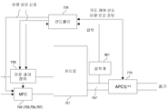
도 7은 실시 형태에 따른 기판 처리 장치인 매엽형 기판 처리 장치의 일 예를 도시하는 개략도이다. 도 7에 도시되는 바와 같이 반응실(701) 내에 상부 개구가 서셉터(702)에 의해 피복된 중공의 히터 유닛(718)이 설치된다. 히터 유닛(718)의 내부에는 히터(703)가 설치되고, 히터(703)에 의해 서셉터(702) 상에 재치되는 웨이퍼(704)를 가열하도록 이루어진다. 서셉터(702) 상에 재치되는 웨이퍼(704)는 예컨대 반도체 실리콘 웨이퍼, 유리 등이다.7 is a schematic view showing an example of a sheet type substrate processing apparatus that is a substrate processing apparatus according to the embodiment. As shown in FIG. 7, a
반응실(701) 외에 기판 회전 유닛(712)이 설치되고, 기판 회전 유닛(712)에 의해 반응실(701) 내의 히터 유닛(718)을 회전하여 서셉터(702) 상의 웨이퍼(704)를 회전할 수 있도록 이루어진다. 웨이퍼(704)를 회전시키는 것은 성막 공정, 개질 공정에서의 기판 처리를 웨이퍼 면내에서 신속하고 균일하게 수행하기 위해서이다.In addition to the
또한 반응실(701) 내의 서셉터(702)의 상방에 다수의 공(孔)(708)을 포함하는 샤워 헤드(706)가 설치된다. 이 샤워 헤드(706)에는 성막 가스를 공급하는 원료 공급관(705)과 래디컬을 공급하는 래디컬 공급관(713)이 공통적으로 접속되어서 성막 가스 또는 래디컬을 샤워 헤드(706)로부터 샤워 형상으로 반응실(701) 내에 분출할 수 있도록 이루어진다. 여기서 샤워 헤드(706)는 성막 공정에서 웨이퍼(704)에 공급하는 성막 가스와, 개질 공정에서 웨이퍼(704)에 공급하는 래디컬을 각각 공급하는 동일한 공급구를 구성한다.In addition, a
반응실(701) 외부에는 성막 원료로서의 유기 액체 원료를 공급하는 성막 원료 공급 유닛(709)과, 성막 원료의 액체 공급 유량을 제어하는 유량 제어 수단으로서의 액체 유량 제어 장치(728)와, 성막 원료를 기화하는 기화기(729)가 설치된다. 또한, 반응실(701) 외부에는 미반응 가스 또는 퍼지 가스로서의 불활성 가스를 공급하는 불활성 가스 공급 유닛(710)과, 불활성 가스의 공급 유량을 제어하는 유량 제어 수단으로서의 MFC(746)가 설치된다. 예컨대 웨이퍼(200) 상에 HfO2막을 성막하는 경우에는 성막 원료로서는 Hf-(MMP)4 등의 유기 재료를 이용한다. 또한 불활성 가스로서는 Ar, He, N2 등을 이용한다. 성막 원료 공급 유닛(709)에 설치된 원료 가스 공급관(705b)과, 불활성 가스 공급 유닛(710)에 설치된 불활성 가스 공급관(705a)을 단일화하여, 샤워 헤드(706)에 접속되는 원료 공급관(705)이 설치된다. 원료 공급관(705)은 웨이퍼(704) 상에 원하는 막을 형성하는 성막 공정에서 샤워 헤드(706)에 제3 원료 가스와 불활성 가스의 혼합 가스를 공급하도록 이루어진다. 원료 가스 공급관(705b), 불활성 가스 공급관(705a)에는 각각 밸브(721, 720)를 설치하고, 이 밸브(721, 720)를 개폐하는 것에 의해 제3 원료 가스와 불활성 가스의 혼합 가스의 공급을 제어하는 것이 가능하도록 이루어진다.Outside the
또한 반응실(701) 외부에는 가스를 플라즈마에 의해 활성화시켜서 반응물로서의 래디컬을 형성하는 플라즈마원으로서 기능하는 반응물 활성화 유닛(711)(리모트 플라즈마 유닛)이 설치된다. 개질 공정에서 이용하는 래디컬은 원료로서 Hf-(MMP)4 등의 유기 재료를 이용하는 경우, 예컨대 산소 래디컬이 좋다. 이는 산소 래디컬에 의해 HfO2막 형성 직후에 C나 H 등의 불순물 제거 처리를 효율적으로 실시할 수 있기 때문이다. 또한 클리닝 공정에서 이용하는 래디컬은 ClF3 래디컬이 좋다. 개질 공정에서 예컨대 산소 함유 가스(O2, N2O, NO 등)를 플라즈마에 의해 분해한 산소 래디컬 분위기에서 막을 산화시키는 처리를 리모트 플라즈마 산화 (RPO: remote plasma oxidation) 처리라고 부른다.Further, outside the
반응물 활성화 유닛(711)의 상류측에는 가스 공급관(737)이 설치된다. 이 가스 공급관(737)에는 제4 원료 가스를 공급하는 제4 원료 가스 공급 유닛(747), 플라즈마를 발생시키는 가스인 제5 원료 가스를 공급하는 제5 원료 가스 공급 유닛(748) 및 제6 원료 가스를 공급하는 제6 원료 가스 공급 유닛(749)이 공급관(752, 753, 754)을 개재하여 접속되고, 개질 공정으로 사용하는 가스 및 클리닝 공정으로 사용하는 가스를 반응물 활성화 유닛(711)에 대하여 공급하도록 이루어진다. 제4 원료 가스 공급 유닛(747), 제5 원료 가스 공급 유닛(748) 및 제6 원료 가스 공급 유닛(749)에는 각각의 가스의 공급 유량을 제어하는 유량 제어 수단으로서의 매스 플로우 컨트롤러(755, 756, 757)가 설치된다. 공급관(752, 753, 754)에는 각각 밸브(758, 759, 760)를 설치하고, 이 밸브(758, 759, 760)를 개폐하는 것에 의해 제4, 제5, 제6 각각의 원료 가스의 공급을 제어하는 것이 가능하도록 이루어진다.A
반응물 활성화 유닛(711)의 하류측에는 샤워 헤드(706)에 접속되는 래디컬 공급관(713)이 설치되고, 개질 공정 또는 클리닝 공정에서 샤워 헤드(706)에 산소 래디컬 또는 불화염소 래디컬을 공급하도록 이루어진다. 또한 래디컬 공급관(713)에는 밸브(724)를 설치하고 밸브(724)를 개폐하는 것에 의해 래디컬의 공급을 제어하는 것이 가능하도록 이루어진다.On the downstream side of the
반응실(701)에 배기구(707a)가 설치되고, 그 배기구(707a)는 제해 장치(도시되지 않음)에 연통하는 배기관(707)에 접속된다. 배기관(707)에는 성막 원료를 회수하기 위한 원료 회수 트랩(716)이 설치된다. 이 원료 회수 트랩(716)은 성막 공정과 개질 공정에 공용으로 이용된다. 원료 회수 트랩(716)의 하류에는 APC 밸브(715)가 설치되고, 배기량의 조절을 수행하여 처리로(701) 내의 압력을 조절한다. 상기 배기구(707a) 및 배기관(707)은 배기 라인을 구성한다.An
또한 원료 가스 공급관(705b) 및 래디컬 공급관(713)에는 배기관(707)에 설치한 원료 회수 트랩(716)에 접속되는 원료 가스 바이패스관(714a) 및 래디컬 바이패스관(714b)[이들을 단순히 바이패스관(714)이라고도 부른다]이 각각 설치된다. 원료 가스 바이패스관(714a) 및 래디컬 바이패스관(714b)에 각각 밸브(722, 723)를 설치한다. 이 밸브의 개폐에 의해 성막 공정에서 반응실(701) 내의 웨이퍼(704)에 성막 가스를 공급할 때에는 개질 공정에서 사용하는 래디컬의 공급은 정지시키지 않고 반응실(701)을 바이패스하도록 래디컬 바이패스관(714b), 원료 회수 트랩(716)을 개재하여 미리 배기한다. 또한 개질 공정에서 웨이퍼(704)에 래디컬을 공급할 때에는 성막 공정에서 사용하는 성막 가스의 공급은 정지시키지 않고 반응실(701)을 바이패스하도록 원료 가스 바이패스관(714a), 원료 회수 트랩(716)을 개재하여 배기한다.In addition, the raw material
그리고 처리로(701) 내에서 웨이퍼(704) 상에 원하는 막을 형성하는 성막 공정과, 성막 공정에서 형성한 원하는 막 중의 특정 원소 등의 불순물을 반응물 활성화 유닛(711)을 이용한 플라즈마 처리에 의해 제거하는 개질 공정을 상기 밸브(720∼724)의 개폐 등을 제어하는 것에 의해 연속적으로 복수 회 반복하도록 제어하는 컨트롤러(725)가 설치된다.The film forming step of forming a desired film on the
여기서 컨트롤러(725)는 제1 실시 형태와 마찬가지로 가스 유량 제어부(235), 압력 제어부(236), 구동 제어부(237), 온도 제어부(238), 주제어부(239)를 포함하고, 또한 액체 유량 제어 장치(728)와 MFC(746, 755, 756, 757)와 APC 밸브(715)에 전기적으로 접속된다.Here, the
여기서 도 8과 도 9를 이용하여 제2 실시 형태의 압력 제어에 대하여 설명한다. 도 8은 본 발명의 제2 실시 형태에 적용되는 기판 처리 장치 주변의 구성을 간략하게 도시한 도면이며, 도 9는 본 발명의 제2 실시 형태에 적용되는 기판 처리 장치의 처리로 내의 압력 설정값과 압력 측정값을 비교한 그래프다. 컨트롤러(725)는 액체 유량 제어 장치(728)와 MFC(746, 755, 756, 757)에 유량 제어 신호를 송신하는 것에 의해 가스 유량을 제어하고, 처리로(701)와 APC 밸브(715) 사이에 설치된 압력계(801)로부터 압력 측정값을 수신하여 APC 밸브(715)에 개도 제어 신호와 유량 변경 정보를 송신하는 것에 의해 처리로(701) 내의 압력을 원하는 압력값으로 유지할 수 있다.Here, the pressure control of 2nd Embodiment is demonstrated using FIG. 8 and FIG. FIG. 8 is a diagram schematically showing a configuration around the substrate processing apparatus applied to the second embodiment of the present invention, and FIG. 9 is a pressure set value in the processing furnace of the substrate processing apparatus applied to the second embodiment of the present invention. This is a graph comparing pressure measurement with. The
즉, 성막 원료 공급 유닛(709)으로부터 공급된 액체 원료를 액체 유량 제어 장치(728)에 의하여 유량 제어하고 기화기(729)에 의하여 기화시킨다. 기화된 원료 가스는 샤워 헤드(706)를 개재하여 처리로 내가 설정된 압력값이 될 때까지 웨이퍼(704) 상에 계속해서 공급된다(S901). 기화된 원료 가스가 공급되는 것에 의해 처리로(701) 내의 압력이 설정된 압력값에 도달하고, 소정의 시간이 경과하면 처리로(701)에 설치된 가스 배기관(707)에 의해 배기되는 것과 함께 불활성 가스 공급 유닛(710)으로부터 불활성 가스가 공급되고, 처리로(701) 내에 공급된 기화 원료 가스가 퍼지된다(S902). 기화 원료 가스가 퍼지되면, 제4 가스 공급 유닛(747)으로부터 공급되는 가스가 반응물 활성화 유닛(711)에 의해 활성화되어 래디컬을 포함하는 가스로서 샤워 헤드(706)를 개재하여 처리로(701) 내가 설정된 압력값이 될 때까지 처리로(701) 내에 공급된다(S903). 래디컬을 포함하는 가스에 의해 처리로(701) 내가 소정의 압력값이 된 후 소정의 시간이 경과하면, 다시 가스 배기관(707)에 의해 배기되는 것과 함께 불활성 가스 공급 유닛(710)으로부터 불활성 가스가 공급되고, 처리로(701) 내에 공급된 래디컬을 포함하는 가스가 퍼지된다(S904).That is, the liquid raw material supplied from the film-forming raw
제1 실시 형태와 마찬가지로, 제2 실시 형태에서도 제1 원료 가스를 공급하는 공정(S901)에서 제1 원료 가스의 공급 시작 직후에는 압력계(801)로부터의 압력값에 기초하여 컨트롤러(725)는 액체 유량 제어 장치(728)에 유량 제어 신호를 송신하여 대유량으로 원료 가스의 공급 유량을 증가시킨다. 처리로(701) 내의 압력이 소정의 압력값에 근접해지면, 압력계(801)로부터의 측정값을 수신한 컨트롤러(725)는 가스 공급 유량이 낮아지도록 액체 유량 제어 장치(728)에 유량 제어 신호를 송신한다. 이에 의하여 제1 원료 가스의 공급량이 제어되어 처리로(701) 내의 압력이 일정하게 유지된다.Similarly to the first embodiment, in the second embodiment, the
또한, 제1 원료 가스를 퍼지하는 공정(S902)에서, 퍼지 공정 시작 직후에는 압력계(801)로부터의 압력값에 기초하여 컨트롤러(725)는 MFC(746)에 유량 제어 신호를 송신하여 불활성 가스의 공급 유량을 증가시키고, APC 밸브(715)에 개도 제어 신호와 유량 변경 신호를 송신하여 배기량을 증가시킨다. 처리로 내의 압력이 소정값 부근까지 저하하면, 압력계(801)로부터의 압력값에 기초하여 컨트롤러(725)는 MFC(746)에 유량 제어 신호를 송신하여 퍼지 가스 공급량을 적절한 양으로 변경하고, APC 밸브(715)에 개도 제어 신호와 유량 변경 정보를 송신하여 배기량이 낮아지도록 제어한다. 제2 원료 가스 공급 공정(S903)이나 제2 원료 가스 퍼지 공정(S904)에서도 마찬가지의 제어를 수행한다. 그러나, 본 발명은 이에 한정되지 않으며, 전술한 제어 내용뿐만 아니라 목적이나 조건에 의해 제어 내용을 변경해도 된다.Further, in the step S902 of purging the first source gas, immediately after the start of the purge step, the
(본 실시 형태에 따른 효과)(Effects according to the present embodiment)
전술한 제2 실시 형태에 의하면, 제1 실시 형태와 마찬가지의 효과를 얻을 수 있다.According to the second embodiment described above, the same effects as in the first embodiment can be obtained.
<본 발명의 다른 실시 형태>≪ Another embodiment of the present invention >
이상, 본 발명의 실시 형태를 구체적으로 설명하였지만 본 발명은 전술한 실시 형태에 한정되지 않고, 그 요지를 일탈하지 않는 범위 내에서 갖가지 변경이 가능하다.As mentioned above, although embodiment of this invention was described concretely, this invention is not limited to embodiment mentioned above, A various change is possible in the range which does not deviate from the summary.
예컨대 본 발명의 제1 실시 형태에서는 뱃치식의 종형 장치에 대하여 설명하였지만, 뱃치식의 횡형(橫型) 장치이어도 좋고, 처리로가 복수 존재하는 종형 또는 횡형의 기판 처리 장치이어도 좋다.For example, in the first embodiment of the present invention, a batch type vertical apparatus has been described, but a batch type horizontal apparatus may be used, or a vertical or horizontal substrate processing apparatus in which a plurality of processing furnaces exist.
마찬가지로 제2 실시 형태에서는 플라즈마를 이용하여 기판 처리를 수행하는 기판 처리 장치에 대하여 설명하였지만 이에 한정되지 않고, 플라즈마를 이용하지 않는 매엽형 기판 처리 장치로 수행해도 좋고, 또한 매엽형 기판 처리 장치는 웨이퍼를 1매씩 처리하는 매엽 장치이어도 좋고, 복수 매 뱃치로 처리하는 다매엽 장치이어도 좋다.Similarly, in the second embodiment, a substrate processing apparatus for performing substrate processing using plasma has been described. However, the present invention is not limited thereto, and the substrate processing apparatus may be performed using a single wafer substrate processing apparatus that does not use plasma. May be a sheet-measuring device for treating each sheet, or may be a multi-sheet device for treating a plurality of sheets.
<본 발명의 바람직한 형태><Preferred embodiment of the present invention>
이하에 본 발명의 바람직한 형태에 대하여 부기한다.Hereinafter, preferred embodiments of the present invention will be described.
(부기1) 기판을 처리하는 처리실과, 처리 가스 원료의 공급 유량을 조절하는 유량 제어 장치와, 압력을 계측하는 압력 검출기와, 상기 처리실 내 압력을 조절하는 압력 조절기와, 적어도 상기 압력 검출기, 상기 압력 조절기 및 상기 유량 제어 장치에 접속되고 상기 압력 검출기에 의해 검출된 압력값에 따라 상기 압력 조절기 및 상기 유량 제어 장치를 제어하는 제어부를 구비한 기판 처리 장치를 이용한 반도체 장치의 제조 방법으로서, 상기 처리실 내의 기판에 대하여 유량 제어 장치를 개재하여 적어도 제1 처리 가스를 공급하는 공정; 상기 제1 처리 가스를 공급하는 공정 후, 상기 처리실 내를 퍼지하는 퍼지 가스를 공급하는 제1 퍼지 공정; 상기 제1 퍼지 공정 후, 적어도 제2 처리 가스를 공급하는 공정; 및 상기 제2 처리 가스를 공급하는 공정 후, 상기 처리실 내를 퍼지하는 퍼지 가스를 공급하는 제2 퍼지 공정;을 포함하는 반도체 장치의 제조 방법.(Supplementary Note 1) A processing chamber for processing a substrate, a flow rate control device for adjusting a supply flow rate of a processing gas raw material, a pressure detector for measuring pressure, a pressure regulator for adjusting a pressure in the processing chamber, and at least the pressure detector, the A method of manufacturing a semiconductor device using a substrate processing apparatus having a control unit connected to a pressure regulator and the flow rate control device and controlling the pressure regulator and the flow rate control device in accordance with a pressure value detected by the pressure detector, wherein the process chamber Supplying at least a first processing gas to a substrate therein via a flow rate control device; A first purge step of supplying a purge gas for purging the inside of the process chamber after the step of supplying the first process gas; Supplying at least a second processing gas after the first purge process; And a second purge step of supplying a purge gas for purging the inside of the process chamber after the step of supplying the second process gas.
(부기2) 기판을 처리하는 처리실과, 처리 가스 원료의 공급 유량을 조절하는 유량 제어 장치와, 압력을 계측하는 압력 검출기와, 상기 처리실 내 압력을 조절하는 압력 조절기와, 적어도 상기 압력 검출기, 상기 압력 조절기 및 상기 유량 제어 장치에 접속되고 상기 압력 검출기에 의해 검출된 압력값에 따라 상기 압력 조절기 및 상기 유량 제어 장치를 제어하는 제어부를 구비한 기판 처리 장치를 이용한 기판 처리 방법으로서, 상기 처리실 내의 기판에 대하여 유량 제어 장치를 개재하여 적어도 제1 처리 가스를 공급하는 공정; 상기 제1 처리 가스를 공급하는 공정 후, 상기 처리실 내를 퍼지하는 퍼지 가스를 공급하는 제1 퍼지 공정; 상기 제1 퍼지 공정 후, 적어도 제2 처리 가스를 공급하는 공정; 및 상기 제2 처리 가스를 공급하는 공정 후, 상기 처리실 내를 퍼지하는 퍼지 가스를 공급하는 제2 퍼지 공정;을 포함하는 기판 처리 방법.(Supplementary Note 2) A processing chamber for processing a substrate, a flow rate control device for adjusting a supply flow rate of a processing gas raw material, a pressure detector for measuring pressure, a pressure regulator for adjusting a pressure in the processing chamber, at least the pressure detector, and A substrate processing method using a substrate processing apparatus having a controller connected to a pressure regulator and the flow rate control device and controlling the pressure regulator and the flow rate control device in accordance with a pressure value detected by the pressure detector, the substrate in the processing chamber. Supplying at least a first processing gas to a via a flow control device; A first purge step of supplying a purge gas for purging the inside of the process chamber after the step of supplying the first process gas; Supplying at least a second processing gas after the first purge process; And a second purge step of supplying a purge gas for purging the inside of the process chamber after the step of supplying the second process gas.
(부기3) 기판을 처리하는 처리실; 상기 처리실 내에 처리 가스를 공급하는 가스 공급원; 상기 가스 공급원으로부터 공급되는 가스의 유량을 가변 하는 가스 유량 제어 장치를 구비한 가스 공급부; 상기 가스 공급부에서 상기 처리실 내에 공급된 가스를 배기하는 배기관; 상기 처리실과 상기 배기관 사이에 설치되고 압력을 측정하는 압력 검출기; 상기 처리실 내의 압력을 조절하는 압력 조절기; 및 적어도 상기 가스 유량 제어 장치와 상기 압력 검출기 및 상기 압력 조절기에 접속되어 상기 압력 검출기의 측정값에 따라 상기 가스 유량 제어 장치와 상기 압력 조절기를 제어하는 제어부;를 포함하는 기판 처리 장치.(Supplementary Note 3) a processing chamber for processing the substrate; A gas supply source supplying a processing gas into the processing chamber; A gas supply unit including a gas flow rate control device that varies a flow rate of a gas supplied from the gas supply source; An exhaust pipe exhausting the gas supplied from the gas supply unit into the processing chamber; A pressure detector installed between the processing chamber and the exhaust pipe and measuring pressure; A pressure regulator controlling a pressure in the processing chamber; And a control unit connected to at least the gas flow rate control device, the pressure detector, and the pressure regulator to control the gas flow rate control device and the pressure regulator in accordance with a measurement value of the pressure detector.
100: 반도체 제조 장치 105: 포드 선반
110: 포드 111: 광체
114: 로드 포트 118: 포드 반송 장치
125: 웨이퍼 이재기 125c: 암
177, 178, 179: 밸브 180: 제1 가스 공급원
181: 제2 가스 공급원 182: 제3 가스 공급원
183, 184, 185: MFC 200: 웨이퍼
201: 반응실 202: 처리로
205: 반응관 206: 히터
209: 매니폴드 217: 보트
217a: 보트 단열부 238: 온도 제어부
235: 가스 유량 제어부 231: 가스 배기관
236: 압력 제어부 219: 씰 캡
237: 구동 제어부 239: 주제어부
240: 컨트롤러 242: APC밸브
244: 볼 나사 248: 승강 모터
249: 승강대 250: 승강 샤프트
254: 회전 기구 255: 회전축
264: 가이드 샤프트 265: 벨로즈
252: 승강 기판 253: 구동부 커버
256: 구동부 수납 케이스 257: 냉각 기구
258: 전력 공급 케이블 259: 냉각수 유로
260: 냉각수 배관100: semiconductor manufacturing apparatus 105: Ford shelf
110: Ford 111:
114: load port 118: Ford conveying device
125:
177, 178, 179: valve 180: first gas source
181: second gas source 182: third gas source
183, 184, 185: MFC 200: Wafer
201: reaction chamber 202: furnace
205: reaction tube 206: heater
209: manifold 217: boat
217a: boat insulation 238: temperature control
235: gas flow control unit 231: gas exhaust pipe
236: pressure control unit 219: seal cap
237: driving control unit 239: main control unit
240: controller 242: APC valve
244: ball screw 248: lifting motor
249: platform 250: lifting shaft
254: rotation mechanism 255: rotation axis
264: guide shaft 265: bellows
252: lifting substrate 253: driving unit cover
256: drive part storage case 257: cooling mechanism
258: power supply cable 259: coolant flow path
260: cooling water piping
Claims (10)
(a) 상기 제1 처리 가스 공급부에 의하여 상기 제1 처리 가스를 상기 유량 제어 장치를 개재하여 상기 처리실 내에 공급하여 상기 기판 상에 상기 제1 막을 형성하는 공정;
(b) 적어도 상기 제1 처리 가스가 상기 처리실 내에 공급된 후 상기 압력 검출기에 의하여 배기 압력이 검출되면, 검출된 상기 배기 압력을 나타내는 신호를 상기 제어부에 송신하는 공정;
(c) 상기 제어부가 상기 신호를 수신하면, 상기 배기 압력이 소정의 압력이 되도록 상기 제어부에 의하여 상기 압력 조절기 및 상기 유량 제어 장치를 제어하는 공정;
(d) 상기 제1 막이 형성된 후, 상기 퍼지 가스 공급부에 의하여 상기 퍼지 가스를 공급하는 공정; 및
(e) 상기 제2 처리 가스 공급부에 의하여 상기 제2 처리 가스를 상기 유량 제어부를 개재하여 상기 처리실 내에 공급하여 상기 제1 막 상에 상기 제2 막을 형성하는 공정
을 포함하는 반도체 장치의 제조 방법.A first processing gas supply unit supplying a processing chamber for processing a substrate and a first processing gas for forming a first film on the substrate; A second processing gas supply unit supplying a second processing gas for forming a second film on the first film; A purge gas supply unit supplying a purge gas for purging an atmosphere in the processing chamber; A flow rate control device for controlling a supply flow rate of each of the first processing gas, the second processing gas, and the purge gas; An exhaust device for exhausting the processing chamber; A pressure detector installed at the exhaust device to detect exhaust pressure; A pressure regulator controlling a pressure in the processing chamber; And a control unit connected to at least the pressure detector and the pressure regulator and the flow rate control device and controlling the pressure regulator and the flow rate control device according to the pressure detected by the pressure detector. As a manufacturing method,
(a) supplying the first processing gas into the processing chamber via the flow control device by the first processing gas supply unit to form the first film on the substrate;
(b) transmitting a signal indicative of the detected exhaust pressure to the controller if exhaust pressure is detected by the pressure detector after at least the first process gas has been supplied into the process chamber;
(c) when the control unit receives the signal, controlling the pressure regulator and the flow rate control device by the control unit so that the exhaust pressure becomes a predetermined pressure;
(d) supplying the purge gas by the purge gas supply unit after the first film is formed; And
(e) supplying the second processing gas into the processing chamber via the flow control unit by the second processing gas supply unit to form the second film on the first film;
Wherein the semiconductor device is a semiconductor device.
상기 (c) 공정은 상기 (b) 공정에서 검출된 상기 배기 압력이 제1 압력 이상인 경우에는, 상기 제1 처리 가스의 공급 유량을 감소시키도록 상기 유량 제어 장치를 제어하는 공정을 포함하는 반도체 장치의 제조 방법.The method of claim 1,
The step (c) includes the step of controlling the flow rate control device to reduce the supply flow rate of the first processing gas when the exhaust pressure detected in the step (b) is equal to or greater than the first pressure. Method of preparation.
(f) 상기 제2 처리 가스가 상기 처리실 내에 공급된 후 배기 압력을 검출하는 공정;
(g) 상기 (f) 공정에서 검출된 상기 배기 압력이 제2 압력 이상인 경우에는, 상기 제2 처리 가스의 공급 유량을 감소시키도록 상기 유량 제어 장치를 제어하는 공정; 및
(h) 상기 퍼지 가스를 상기 처리실 내에 공급하는 공정
을 더 포함하는 반도체 장치의 제조 방법.The method of claim 1,
(f) detecting exhaust pressure after the second processing gas is supplied into the processing chamber;
(g) controlling the flow rate control device to reduce the supply flow rate of the second processing gas when the exhaust pressure detected in the step (f) is equal to or greater than the second pressure; And
(h) supplying the purge gas into the processing chamber
Further comprising the steps of:
상기 유량 제어 장치는 매스 플로우 컨트롤러를 포함하는 반도체 장치의 제조 방법.The method of claim 1,
The flow rate control device includes a mass flow controller.
상기 압력 조절기는 APC 밸브를 포함하는 반도체 장치의 제조 방법.The method of claim 1,
And the pressure regulator comprises an APC valve.
(a) 상기 제1 처리 가스 공급부에 의하여 상기 제1 처리 가스를 상기 유량 제어 장치를 개재하여 상기 처리실 내에 공급하여 상기 기판 상에 상기 제1 막을 형성하는 공정;
(b) 적어도 상기 제1 처리 가스가 상기 처리실 내에 공급된 후 상기 압력 검출기에 의하여 배기 압력이 검출되면, 검출된 상기 배기 압력을 나타내는 신호를 상기 제어부에 송신하는 공정;
(c) 상기 제어부가 상기 신호를 수신하면, 상기 배기 압력이 소정의 압력이 되도록 상기 제어부에 의하여 상기 압력 조절기 및 상기 유량 제어 장치를 제어하는 공정;
(d) 상기 제1 막이 형성된 후, 상기 퍼지 가스 공급부에 의하여 상기 퍼지 가스를 공급하는 공정; 및
(e) 상기 제2 처리 가스 공급부에 의하여 상기 제2 처리 가스를 상기 유량 제어부를 개재하여 상기 처리실 내에 공급하여 상기 제1 막 상에 상기 제2 막을 형성하는 공정
을 포함하는 기판 처리 방법.A first processing gas supply unit supplying a processing chamber for processing a substrate and a first processing gas for forming a first film on the substrate; A second processing gas supply unit supplying a second processing gas for forming a second film on the first film; A purge gas supply unit supplying a purge gas for purging an atmosphere in the processing chamber; A flow rate control device for controlling a supply flow rate of each of the first processing gas, the second processing gas, and the purge gas; An exhaust device for exhausting the processing chamber; A pressure detector installed at the exhaust device to detect exhaust pressure; A pressure regulator controlling a pressure in the processing chamber; And a control unit connected to at least the pressure detector, the pressure regulator, and the flow rate control device and controlling the pressure regulator and the flow rate control device in accordance with the pressure detected by the pressure detector. As
(a) supplying the first processing gas into the processing chamber via the flow control device by the first processing gas supply unit to form the first film on the substrate;
(b) transmitting a signal indicative of the detected exhaust pressure to the controller if exhaust pressure is detected by the pressure detector after at least the first process gas has been supplied into the process chamber;
(c) when the control unit receives the signal, controlling the pressure regulator and the flow rate control device by the control unit so that the exhaust pressure becomes a predetermined pressure;
(d) supplying the purge gas by the purge gas supply unit after the first film is formed; And
(e) supplying the second processing gas into the processing chamber via the flow control unit by the second processing gas supply unit to form the second film on the first film;
≪ / RTI >
상기 기판 상에 제1 막을 형성하기 위한 제1 처리 가스를 공급하는 제1 처리 가스 공급부;
상기 제1 막 상에 제2 막을 형성하기 위한 제2 처리 가스를 공급하는 제2 처리 가스 공급부;
상기 처리실 내의 분위기를 퍼지하는 퍼지 가스를 공급하는 퍼지 가스 공급부;
상기 제1 처리 가스, 제2 처리 가스 및 퍼지 가스 각각의 공급 유량을 조절하는 유량 제어 장치;
상기 처리실을 배기하는 배기 장치;
상기 배기 장치에 설치되어 배기 압력을 검출하는 압력 검출기;
상기 처리실 내의 압력을 조절하는 압력 조절기; 및
적어도 상기 압력 검출기, 상기 압력 조절기 및 상기 유량 제어 장치에 접속되고, 상기 압력 검출기에 의해 검출된 압력에 따라 상기 압력 조절기 및 상기 유량 제어 장치를 제어하는 제어부
를 구비하는 기판 처리 장치.A processing chamber for processing the substrate;
A first processing gas supply unit supplying a first processing gas for forming a first film on the substrate;
A second processing gas supply unit supplying a second processing gas for forming a second film on the first film;
A purge gas supply unit supplying a purge gas for purging an atmosphere in the processing chamber;
A flow rate control device for adjusting a supply flow rate of each of the first process gas, the second process gas, and the purge gas;
An exhaust device for exhausting the processing chamber;
A pressure detector installed at the exhaust device to detect exhaust pressure;
A pressure regulator controlling a pressure in the processing chamber; And
A control unit connected to at least the pressure detector, the pressure regulator, and the flow rate control device, the control unit controlling the pressure regulator and the flow rate control device according to the pressure detected by the pressure detector.
And the substrate processing apparatus.
상기 압력 검출기는 상기 배기 압력을 검출하면 검출된 상기 배기 압력을 나타내는 신호를 상기 제어부에 송신하고,
상기 제어부는 상기 압력 검출기로부터 수신된 상기 신호에 기초하여 상기 처리실 내의 압력이 소정의 압력이 되도록 상기 압력 조절기와 상기 유량 제어 장치를 제어하는 기판 처리 장치.The method of claim 7, wherein
The pressure detector transmits a signal indicating the detected exhaust pressure to the controller when detecting the exhaust pressure.
And the control unit controls the pressure regulator and the flow rate control device such that the pressure in the processing chamber becomes a predetermined pressure based on the signal received from the pressure detector.
상기 유량 제어 장치는 매스 플로우 컨트롤러를 포함하는 기판 처리 장치.The method of claim 7, wherein
The flow rate control device includes a mass flow controller.
상기 압력 조절기는 APC 밸브를 포함하는 기판 처리 장치.The method of claim 7, wherein
The pressure regulator includes an APC valve.
Applications Claiming Priority (2)
| Application Number | Priority Date | Filing Date | Title |
|---|---|---|---|
| JPJP-P-2012-178640 | 2012-08-10 | ||
| JP2012178640A JP6061545B2 (en) | 2012-08-10 | 2012-08-10 | Semiconductor device manufacturing method, substrate processing method, and substrate processing apparatus |
Related Child Applications (1)
| Application Number | Title | Priority Date | Filing Date |
|---|---|---|---|
| KR1020150099498A Division KR101614275B1 (en) | 2012-08-10 | 2015-07-14 | Method of manufacturing semiconductor device, method of processing substrate and substrate processing apparatus |
Publications (1)
| Publication Number | Publication Date |
|---|---|
| KR20140020782A true KR20140020782A (en) | 2014-02-19 |
Family
ID=50066492
Family Applications (2)
| Application Number | Title | Priority Date | Filing Date |
|---|---|---|---|
| KR1020130094066A KR20140020782A (en) | 2012-08-10 | 2013-08-08 | Method of manufacturing semiconductor device, method of processing substrate and substrate processing apparatus |
| KR1020150099498A KR101614275B1 (en) | 2012-08-10 | 2015-07-14 | Method of manufacturing semiconductor device, method of processing substrate and substrate processing apparatus |
Family Applications After (1)
| Application Number | Title | Priority Date | Filing Date |
|---|---|---|---|
| KR1020150099498A KR101614275B1 (en) | 2012-08-10 | 2015-07-14 | Method of manufacturing semiconductor device, method of processing substrate and substrate processing apparatus |
Country Status (4)
| Country | Link |
|---|---|
| US (1) | US8791031B2 (en) |
| JP (1) | JP6061545B2 (en) |
| KR (2) | KR20140020782A (en) |
| TW (1) | TWI547993B (en) |
Cited By (1)
| Publication number | Priority date | Publication date | Assignee | Title |
|---|---|---|---|---|
| KR20190005246A (en) * | 2019-01-07 | 2019-01-15 | 무진전자 주식회사 | Apparatus for wafer treatment |
Families Citing this family (11)
| Publication number | Priority date | Publication date | Assignee | Title |
|---|---|---|---|---|
| KR101427726B1 (en) * | 2011-12-27 | 2014-08-07 | 가부시키가이샤 히다치 고쿠사이 덴키 | Substrate processing apparatus and method of manufacturing semiconductor device |
| US10100407B2 (en) * | 2014-12-19 | 2018-10-16 | Lam Research Corporation | Hardware and process for film uniformity improvement |
| KR102487805B1 (en) * | 2015-04-28 | 2023-01-12 | 주성엔지니어링(주) | Apparatus and method for processing substrate |
| SG11201800143RA (en) * | 2015-08-04 | 2018-02-27 | Hitachi Int Electric Inc | Substrate processing device, semiconductor device manufacturing method, and recording medium |
| US11332824B2 (en) | 2016-09-13 | 2022-05-17 | Lam Research Corporation | Systems and methods for reducing effluent build-up in a pumping exhaust system |
| US10115607B2 (en) * | 2016-09-16 | 2018-10-30 | Applied Materials, Inc. | Method and apparatus for wafer outgassing control |
| JP6763274B2 (en) * | 2016-10-14 | 2020-09-30 | 東京エレクトロン株式会社 | Film forming equipment, cleaning method of film forming equipment and storage medium |
| JP6864705B2 (en) * | 2018-03-29 | 2021-04-28 | 株式会社Kokusai Electric | Manufacturing method of substrate processing equipment, control system and semiconductor equipment |
| JP6681452B1 (en) * | 2018-10-19 | 2020-04-15 | 株式会社Kokusai Electric | Substrate processing apparatus and semiconductor device manufacturing method |
| KR102208815B1 (en) * | 2019-05-10 | 2021-01-28 | 주식회사 뉴파워 프라즈마 | Control method of substrate processing system |
| CN115440633B (en) * | 2022-10-17 | 2023-07-11 | 北京北方华创微电子装备有限公司 | Semiconductor process equipment and exhaust gas adjusting mechanism |
Family Cites Families (14)
| Publication number | Priority date | Publication date | Assignee | Title |
|---|---|---|---|---|
| US5758680A (en) * | 1996-03-29 | 1998-06-02 | Lam Research Corporation | Method and apparatus for pressure control in vacuum processors |
| US6142163A (en) * | 1996-03-29 | 2000-11-07 | Lam Research Corporation | Method and apparatus for pressure control in vacuum processors |
| JP2003209063A (en) * | 2001-11-08 | 2003-07-25 | Tokyo Electron Ltd | Heat treatment apparatus and method therefor |
| WO2008016143A1 (en) * | 2006-08-04 | 2008-02-07 | Hitachi Kokusai Electric Inc. | Substrate processing apparatus and semiconductor device manufacturing method |
| JP2008235611A (en) * | 2007-03-21 | 2008-10-02 | Tohoku Univ | Plasma processing equipment and method for processing plasma |
| JP5060916B2 (en) * | 2007-11-05 | 2012-10-31 | 株式会社日立国際電気 | Substrate processing apparatus, semiconductor device manufacturing method, and substrate processing method |
| JP2009218262A (en) * | 2008-03-07 | 2009-09-24 | Omron Corp | Electronic device manufacturing method using plasma reaction furnace |
| JP2010073823A (en) * | 2008-09-17 | 2010-04-02 | Tokyo Electron Ltd | Film deposition apparatus, film deposition method and computer-readable storage medium |
| JP2011044446A (en) * | 2009-08-19 | 2011-03-03 | Tokyo Electron Ltd | Pressure control apparatus, pressure control method and substrate processing apparatus |
| JP2011134781A (en) * | 2009-12-22 | 2011-07-07 | Hitachi Kokusai Electric Inc | Method of manufacturing semiconductor device, and substrate processing device |
| JP5470149B2 (en) * | 2010-04-23 | 2014-04-16 | 株式会社日立国際電気 | Substrate processing apparatus, semiconductor device manufacturing method and cleaning method |
| TWI520177B (en) * | 2010-10-26 | 2016-02-01 | Hitachi Int Electric Inc | Substrate processing apparatus , semiconductor device manufacturing method and computer-readable recording medium |
| JP5921168B2 (en) * | 2011-11-29 | 2016-05-24 | 株式会社日立国際電気 | Substrate processing equipment |
| JP5960614B2 (en) * | 2012-03-29 | 2016-08-02 | Ckd株式会社 | Fluid control system and fluid control method |
-
2012
- 2012-08-10 JP JP2012178640A patent/JP6061545B2/en active Active
-
2013
- 2013-08-08 TW TW102128460A patent/TWI547993B/en active
- 2013-08-08 KR KR1020130094066A patent/KR20140020782A/en not_active IP Right Cessation
- 2013-08-09 US US13/963,695 patent/US8791031B2/en active Active
-
2015
- 2015-07-14 KR KR1020150099498A patent/KR101614275B1/en active IP Right Grant
Cited By (1)
| Publication number | Priority date | Publication date | Assignee | Title |
|---|---|---|---|---|
| KR20190005246A (en) * | 2019-01-07 | 2019-01-15 | 무진전자 주식회사 | Apparatus for wafer treatment |
Also Published As
| Publication number | Publication date |
|---|---|
| US8791031B2 (en) | 2014-07-29 |
| TW201421573A (en) | 2014-06-01 |
| JP2014036216A (en) | 2014-02-24 |
| KR20150088229A (en) | 2015-07-31 |
| JP6061545B2 (en) | 2017-01-18 |
| US20140045278A1 (en) | 2014-02-13 |
| KR101614275B1 (en) | 2016-04-21 |
| TWI547993B (en) | 2016-09-01 |
Similar Documents
| Publication | Publication Date | Title |
|---|---|---|
| KR101614275B1 (en) | Method of manufacturing semiconductor device, method of processing substrate and substrate processing apparatus | |
| KR100932168B1 (en) | Method of manufacturing substrate processing apparatus and semiconductor device | |
| US8529701B2 (en) | Substrate processing apparatus | |
| US10131992B2 (en) | Substrate processing apparatus, method of controlling substrate processing apparatus, method of maintaining substrate processing apparatus, and recording medium | |
| US20100151682A1 (en) | Method of manufacturing semiconductor device and substrate processing apparatus | |
| KR100996689B1 (en) | Manufacturing method of semiconductor apparatus, film forming method and substrate processing apparatus | |
| JP5235142B2 (en) | Semiconductor device manufacturing method and substrate processing apparatus | |
| JPWO2014157071A1 (en) | Substrate processing apparatus, semiconductor device manufacturing method, and substrate processing method | |
| JP2011181817A (en) | Substrate processing apparatus | |
| KR20210127738A (en) | Semiconductor device manufacturing method, substrate processing apparatus and program | |
| KR101550590B1 (en) | Method of manufacturing semiconductor device, method of processing substrate and substrate processing apparatus | |
| JP2013197507A (en) | Substrate processing apparatus, substrate processing method, and semiconductor device manufacturing method | |
| KR101070668B1 (en) | Method of manufacturing semiconductor device and substrate processing apparatus | |
| JP4880408B2 (en) | Substrate processing apparatus, substrate processing method, semiconductor device manufacturing method, main controller, and program | |
| JP2013062271A (en) | Substrate processing apparatus | |
| JP2008172061A (en) | Temperature controlling system, substrate processor, and manufacturing method of semiconductor device | |
| JP2012191191A (en) | Substrate processing apparatus | |
| JP2012195355A (en) | Substrate processing device and substrate manufacturing method | |
| JP2014179550A (en) | Substrate processing apparatus | |
| JP2007258630A (en) | Board processing device | |
| JP2007227470A (en) | Substrate processor | |
| KR20210052222A (en) | Method of manufacturing semiconductor device, program and substrate processing apparatus | |
| WO2004057656A1 (en) | Substrate processing device and semiconductor device producing method | |
| JP2008072054A (en) | Substrate processing apparatus | |
| JP2009117555A (en) | Substrate treatment equipment |
Legal Events
| Date | Code | Title | Description |
|---|---|---|---|
| A201 | Request for examination | ||
| E902 | Notification of reason for refusal | ||
| AMND | Amendment | ||
| AMND | Amendment | ||
| E801 | Decision on dismissal of amendment | ||
| A107 | Divisional application of patent | ||
| SUBM | Surrender of laid-open application requested |