KR20130143097A - Mounting base - Google Patents
Mounting base Download PDFInfo
- Publication number
- KR20130143097A KR20130143097A KR1020137017370A KR20137017370A KR20130143097A KR 20130143097 A KR20130143097 A KR 20130143097A KR 1020137017370 A KR1020137017370 A KR 1020137017370A KR 20137017370 A KR20137017370 A KR 20137017370A KR 20130143097 A KR20130143097 A KR 20130143097A
- Authority
- KR
- South Korea
- Prior art keywords
- bolt
- bottom plate
- foundation
- base
- concrete floor
- Prior art date
Links
- 239000004567 concrete Substances 0.000 claims abstract description 320
- 229910000831 Steel Inorganic materials 0.000 claims abstract description 186
- 239000010959 steel Substances 0.000 claims abstract description 186
- 238000009434 installation Methods 0.000 claims abstract description 165
- 239000004568 cement Substances 0.000 claims description 112
- 239000000463 material Substances 0.000 claims description 70
- 238000004078 waterproofing Methods 0.000 claims description 65
- 238000000034 method Methods 0.000 claims description 47
- 238000012790 confirmation Methods 0.000 claims description 14
- 229910052751 metal Inorganic materials 0.000 abstract description 430
- 239000002184 metal Substances 0.000 abstract description 430
- 239000004570 mortar (masonry) Substances 0.000 abstract description 133
- 238000010276 construction Methods 0.000 abstract description 97
- 238000003780 insertion Methods 0.000 abstract description 94
- 230000037431 insertion Effects 0.000 abstract description 94
- 239000010410 layer Substances 0.000 description 107
- 239000012778 molding material Substances 0.000 description 54
- XLYOFNOQVPJJNP-UHFFFAOYSA-N water Substances O XLYOFNOQVPJJNP-UHFFFAOYSA-N 0.000 description 36
- 238000004519 manufacturing process Methods 0.000 description 30
- 230000003014 reinforcing effect Effects 0.000 description 24
- 238000005553 drilling Methods 0.000 description 20
- 239000010426 asphalt Substances 0.000 description 19
- 238000009415 formwork Methods 0.000 description 19
- 238000003466 welding Methods 0.000 description 16
- 239000000853 adhesive Substances 0.000 description 12
- 230000001070 adhesive effect Effects 0.000 description 12
- XEEYBQQBJWHFJM-UHFFFAOYSA-N Iron Chemical compound [Fe] XEEYBQQBJWHFJM-UHFFFAOYSA-N 0.000 description 8
- 230000007246 mechanism Effects 0.000 description 8
- 230000002093 peripheral effect Effects 0.000 description 8
- 238000004378 air conditioning Methods 0.000 description 7
- 230000007797 corrosion Effects 0.000 description 7
- 238000005260 corrosion Methods 0.000 description 7
- 238000011900 installation process Methods 0.000 description 7
- 238000000465 moulding Methods 0.000 description 7
- 229920005989 resin Polymers 0.000 description 7
- 239000011347 resin Substances 0.000 description 7
- 239000000956 alloy Substances 0.000 description 4
- 229910045601 alloy Inorganic materials 0.000 description 4
- 229910052782 aluminium Inorganic materials 0.000 description 4
- XAGFODPZIPBFFR-UHFFFAOYSA-N aluminium Chemical compound [Al] XAGFODPZIPBFFR-UHFFFAOYSA-N 0.000 description 4
- 230000006866 deterioration Effects 0.000 description 4
- 229910052742 iron Inorganic materials 0.000 description 4
- 239000011150 reinforced concrete Substances 0.000 description 4
- 239000011800 void material Substances 0.000 description 4
- 230000004927 fusion Effects 0.000 description 3
- 239000011796 hollow space material Substances 0.000 description 3
- 230000000379 polymerizing effect Effects 0.000 description 3
- 238000004904 shortening Methods 0.000 description 3
- 239000012790 adhesive layer Substances 0.000 description 2
- 238000013459 approach Methods 0.000 description 2
- 230000000903 blocking effect Effects 0.000 description 2
- 238000002844 melting Methods 0.000 description 2
- 230000008018 melting Effects 0.000 description 2
- 239000012779 reinforcing material Substances 0.000 description 2
- 239000004593 Epoxy Substances 0.000 description 1
- JOYRKODLDBILNP-UHFFFAOYSA-N Ethyl urethane Chemical compound CCOC(N)=O JOYRKODLDBILNP-UHFFFAOYSA-N 0.000 description 1
- BZHJMEDXRYGGRV-UHFFFAOYSA-N Vinyl chloride Chemical compound ClC=C BZHJMEDXRYGGRV-UHFFFAOYSA-N 0.000 description 1
- 238000012423 maintenance Methods 0.000 description 1
- 238000003825 pressing Methods 0.000 description 1
- 239000000758 substrate Substances 0.000 description 1
- 229920003002 synthetic resin Polymers 0.000 description 1
- 239000000057 synthetic resin Substances 0.000 description 1
Images


Classifications
-
- E—FIXED CONSTRUCTIONS
- E04—BUILDING
- E04D—ROOF COVERINGS; SKY-LIGHTS; GUTTERS; ROOF-WORKING TOOLS
- E04D13/00—Special arrangements or devices in connection with roof coverings; Protection against birds; Roof drainage ; Sky-lights
- E04D13/14—Junctions of roof sheathings to chimneys or other parts extending above the roof
- E04D13/1407—Junctions of roof sheathings to chimneys or other parts extending above the roof for flat roofs
-
- E—FIXED CONSTRUCTIONS
- E02—HYDRAULIC ENGINEERING; FOUNDATIONS; SOIL SHIFTING
- E02D—FOUNDATIONS; EXCAVATIONS; EMBANKMENTS; UNDERGROUND OR UNDERWATER STRUCTURES
- E02D27/00—Foundations as substructures
- E02D27/32—Foundations for special purposes
-
- E—FIXED CONSTRUCTIONS
- E04—BUILDING
- E04C—STRUCTURAL ELEMENTS; BUILDING MATERIALS
- E04C5/00—Reinforcing elements, e.g. for concrete; Auxiliary elements therefor
-
- E—FIXED CONSTRUCTIONS
- E04—BUILDING
- E04B—GENERAL BUILDING CONSTRUCTIONS; WALLS, e.g. PARTITIONS; ROOFS; FLOORS; CEILINGS; INSULATION OR OTHER PROTECTION OF BUILDINGS
- E04B1/00—Constructions in general; Structures which are not restricted either to walls, e.g. partitions, or floors or ceilings or roofs
- E04B1/16—Structures made from masses, e.g. of concrete, cast or similarly formed in situ with or without making use of additional elements, such as permanent forms, substructures to be coated with load-bearing material
- E04B1/165—Structures made from masses, e.g. of concrete, cast or similarly formed in situ with or without making use of additional elements, such as permanent forms, substructures to be coated with load-bearing material with elongated load-supporting parts, cast in situ
-
- E—FIXED CONSTRUCTIONS
- E04—BUILDING
- E04B—GENERAL BUILDING CONSTRUCTIONS; WALLS, e.g. PARTITIONS; ROOFS; FLOORS; CEILINGS; INSULATION OR OTHER PROTECTION OF BUILDINGS
- E04B1/00—Constructions in general; Structures which are not restricted either to walls, e.g. partitions, or floors or ceilings or roofs
- E04B1/38—Connections for building structures in general
- E04B1/41—Connecting devices specially adapted for embedding in concrete or masonry
-
- F—MECHANICAL ENGINEERING; LIGHTING; HEATING; WEAPONS; BLASTING
- F16—ENGINEERING ELEMENTS AND UNITS; GENERAL MEASURES FOR PRODUCING AND MAINTAINING EFFECTIVE FUNCTIONING OF MACHINES OR INSTALLATIONS; THERMAL INSULATION IN GENERAL
- F16M—FRAMES, CASINGS OR BEDS OF ENGINES, MACHINES OR APPARATUS, NOT SPECIFIC TO ENGINES, MACHINES OR APPARATUS PROVIDED FOR ELSEWHERE; STANDS; SUPPORTS
- F16M9/00—Special layout of foundations with respect to machinery to be supported
-
- F—MECHANICAL ENGINEERING; LIGHTING; HEATING; WEAPONS; BLASTING
- F24—HEATING; RANGES; VENTILATING
- F24S—SOLAR HEAT COLLECTORS; SOLAR HEAT SYSTEMS
- F24S25/00—Arrangement of stationary mountings or supports for solar heat collector modules
- F24S25/60—Fixation means, e.g. fasteners, specially adapted for supporting solar heat collector modules
- F24S25/61—Fixation means, e.g. fasteners, specially adapted for supporting solar heat collector modules for fixing to the ground or to building structures
- F24S25/617—Elements driven into the ground, e.g. anchor-piles; Foundations for supporting elements; Connectors for connecting supporting structures to the ground or to flat horizontal surfaces
-
- F—MECHANICAL ENGINEERING; LIGHTING; HEATING; WEAPONS; BLASTING
- F24—HEATING; RANGES; VENTILATING
- F24F—AIR-CONDITIONING; AIR-HUMIDIFICATION; VENTILATION; USE OF AIR CURRENTS FOR SCREENING
- F24F13/00—Details common to, or for air-conditioning, air-humidification, ventilation or use of air currents for screening
- F24F13/32—Supports for air-conditioning, air-humidification or ventilation units
-
- Y—GENERAL TAGGING OF NEW TECHNOLOGICAL DEVELOPMENTS; GENERAL TAGGING OF CROSS-SECTIONAL TECHNOLOGIES SPANNING OVER SEVERAL SECTIONS OF THE IPC; TECHNICAL SUBJECTS COVERED BY FORMER USPC CROSS-REFERENCE ART COLLECTIONS [XRACs] AND DIGESTS
- Y02—TECHNOLOGIES OR APPLICATIONS FOR MITIGATION OR ADAPTATION AGAINST CLIMATE CHANGE
- Y02E—REDUCTION OF GREENHOUSE GAS [GHG] EMISSIONS, RELATED TO ENERGY GENERATION, TRANSMISSION OR DISTRIBUTION
- Y02E10/00—Energy generation through renewable energy sources
- Y02E10/40—Solar thermal energy, e.g. solar towers
- Y02E10/47—Mountings or tracking
Landscapes
- Engineering & Computer Science (AREA)
- Architecture (AREA)
- General Engineering & Computer Science (AREA)
- Structural Engineering (AREA)
- Civil Engineering (AREA)
- Physics & Mathematics (AREA)
- Mechanical Engineering (AREA)
- Life Sciences & Earth Sciences (AREA)
- Chemical & Material Sciences (AREA)
- Sustainable Development (AREA)
- Sustainable Energy (AREA)
- Thermal Sciences (AREA)
- Combustion & Propulsion (AREA)
- Electromagnetism (AREA)
- General Life Sciences & Earth Sciences (AREA)
- Paleontology (AREA)
- Mining & Mineral Resources (AREA)
- Foundations (AREA)
- Joining Of Building Structures In Genera (AREA)
- Working Measures On Existing Buildindgs (AREA)
Abstract
<과제> 설치에 필요로 하는 노력이나 비용을 저감할 수가 있음과 아울러, 시공기간을 단축할 수가 있는 설치 기초를 제공한다.
<해결 수단> 설치 기초(10A)는 금속 토대(16)와, 토대(16)의 높이 치수를 조절하는 높이 조절 볼트(18)와, 지지 볼트 삽통공(39, 40)에 삽통된 지지 볼트(19)와, 토대(16)에 설치된 금속 덮개(17)와, 콘크리트 마루(12)의 상면과 토대(16)의 사이의 공간(46)에 충전된 모르타르(20)로 형성되어 있다. 기초(10A)에서는 볼트(19)의 제1고정 단부(47)가 금속판(24)에 개구하는 삽통공(39)에 삽통되어 너트(50)를 통해 금속판(24)에 고정되고, 볼트(19)의 제2고정 단부(48)가 철골 들보(56)에 너트(51)를 통해 고정되고, 볼트(19)의 제1고정 단부(47) 중의 콘크리트 마루(12)의 상면과 금속판(24)의 사이로 뻗는 부분이 공간(46)에 충전된 모르타르(20)와 일체로 되고, 금속 덮개(17)가 토대(16)의 금속관(23)의 정부 개구(27)를 폐색하고 있다.<Problem> It provides installation base that can reduce effort and cost required for installation and shorten construction period.
Solution The mounting base 10A includes a metal base 16, a height adjustment bolt 18 for adjusting the height dimension of the base 16, and a support bolt inserted into the support bolt insertion holes 39 and 40 ( 19, the metal cover 17 provided in the base 16, and the mortar 20 filled in the space 46 between the upper surface of the concrete floor 12 and the base 16 are formed. In the base 10A, the first fixed end 47 of the bolt 19 is inserted into the insertion hole 39 opening in the metal plate 24 to be fixed to the metal plate 24 through the nut 50, and the bolt 19 The second fixed end 48 of) is fixed to the steel beams 56 via the nut 51, the upper surface of the concrete floor 12 of the first fixed end 47 of the bolt 19 and the metal plate 24. A portion extending between the ones is integrated with the mortar 20 filled in the space 46, and the metal cover 17 blocks the government opening 27 of the metal pipe 23 of the base 16.

Description
본 발명은 설치 기초에 관한 것으로, 보다 상세하게는 철골 기둥 및 철골 들보로 형성된 철골 몸체와 철골 몸체에 시설된 콘크리트 마루(floor)를 가지는 철골 구조물에 태양 전지판이나 안테나, 저수조, 정화조, 공기조절 기기 등의 기계 기구, 철탑이나 철골 건설물 등의 건축물을 설치하기 위해서 사용하는 설치 기초에 관한 것이다.The present invention relates to an installation base, and more particularly, to a steel structure having a steel body formed of steel pillars and steel beams and a concrete floor installed in the steel body, solar panels or antennas, water tanks, septic tanks, air conditioning equipment. The present invention relates to a mounting base used to install a building such as a mechanical appliance such as a steel tower, a steel tower, or a steel frame construction.
신설 또는 기설의 철근 콘크리트 구조나 철근 철골 콘크리트 구조 등의 콘크리트 구조물에서는, 옥상이나 지하의 슬라브에 태양 전지판이나 안테나, 저수조, 정화조, 공기조절 기기 등의 여러 가지 기계 기구, 철탑이나 철골 건설물 등의 여러 가지 건축물이 설치된다. 통상적으로 이러한 기계 기구나 건축물은, 그 내부에의 물의 침입을 방지할 목적, 기계 기구나 건축물의 배면측의 유지관리를 가능하게 할 목적으로부터 이들이 콘크리트 슬라브의 상면에 직접적으로 설치되는 일은 없고, 이들이 슬라브에 설치된 설치 기초 상에 설치된다.In concrete structures such as new or existing reinforced concrete structures or reinforced steel concrete structures, various mechanical mechanisms such as solar panels, antennas, reservoirs, septic tanks, air conditioning equipment, steel towers, steel structures, etc. Various buildings are installed. Typically, these mechanical mechanisms and buildings are not directly installed on the upper surface of the concrete slab for the purpose of preventing the ingress of water into the interior thereof, or for the purpose of enabling the maintenance of the back side of the mechanical mechanisms and buildings. It is installed on the mounting base installed on the slab.
이러한 설치 기초의 일례로서 특허 문헌 1은 태양전지 패널 설치 구조를 개시하고 있다. 특허 문헌 1에 있어서 설명되어 있는 종래 기술에서는, 태양전지 패널의 시공 현장의 설치 개소에 있어서 거푸집을 제작하고, 그 거푸집 내에 콘크리트를 타설·양생함으로써 기초를 만들고, 반송되어 온 태양전지 패널 및 그 가대(架臺)를 그 기초 상에 설치하는 구조이다. 그러한 종래 기술의 설치 기초에서는, 시공 현장에서 거푸집을 제작해야 하기 때문에, 그 만큼이 시간이 드는 것은 물론, 거푸집 내에 유입시킨 콘크리트의 양생에 시간이 걸려 짧은 시공기간에 설치 구조를 만들 수가 없다.As an example of such a mounting foundation,
이와 관련된 종래 기술의 문제점을 해결하기 위해서, 특허 문헌 1에 명시된 태양전지 패널 설치 구조에서는, 기초 부품 제조 공장에 있어서 콘크리트제 또는 철근 콘크리트제의 기초를 미리 제조하고, 그 기초를 콘크리트 구조물의 옥상이나 지하의 시공 현장으로 반송한다. 그 후, 옥상이나 지하의 슬라브의 설치 개소에 얇은 시멘트층을 형성하고, 그 시멘트층을 접착층으로 하여 그 위에 기초를 얹어 슬라브와 일체화하고, 태양전지 패널의 설치용 가대를 이들의 기초 상에 설치한다. 특허 문헌 1에 개시된 태양전지 패널 설치 구조는, 태양전지 패널을 설치하기 위한 기초를 형성할 때에 시공 현장에 있어서 거푸집을 제작할 필요가 없기 때문에, 그 만큼의 수고를 줄일 수 있어 시공 현장에 있어서의 시공 작업을 간략화할 수가 있음과 아울러, 콘크리트를 양생하는 시간을 덜 수가 있어 그 만큼의 시공기간을 단축할 수가 있다.In order to solve the related problems of the related art, in the solar cell panel installation structure described in
상기 특허 문헌 1에 명시된 태양전지 패널 설치 구조에서는, 시공 현장에 있어서 콘크리트를 양생할 필요는 없지만, 기초 부품 제조 공장에 있어서 콘크리트를 양생하여 기초를 만들지 않으면 안 되어, 기초의 제조에 콘크리트의 양생이 필요한 것에 변화는 없고, 기초의 제조에 시간을 필요로 한다. 또한, 제조한 기초를 공장으로부터 시공 현장으로 반송할 필요가 있어 상당한 중량을 가지는 기초를 반송하는 수고를 필요로 하기 때문에, 기초를 시공하는 노력이나 비용을 저감할 수가 없다. 또, 공장에서 제조된 기초를 슬라브에 고정하는 경우, 콘크리트층을 접착층으로 하여 슬라브에 고정하는 방법이나 오목부를 슬라브에 형성하여 기초의 하단을 그 오목부에 끼워넣는 방법밖에 채용하지 못하여 기초를 슬라브에 강고하게 고정시킬 수가 없다.In the solar cell panel installation structure described in
본 발명의 목적은, 설치에 필요로 하는 노력이나 비용을 저감할 수가 있음과 아울러, 시공기간을 단축할 수가 있는 설치 기초를 제공하는 것에 있다. 본 발명의 다른 목적은, 철골 구조물에 강고하게 설치할 수가 있고, 기계 기기나 건축물을 강고하게 설치할 수가 있는 설치 기초를 제공하는 것에 있다.An object of the present invention is to provide an installation base that can reduce the effort and cost required for installation and can shorten the construction period. Another object of the present invention is to provide an installation base that can be firmly installed in a steel frame structure and that can be installed firmly in a mechanical device or a building.
상기 과제를 해결하기 위한 제1 및 제2 발명의 전제는, 철골 기둥 및 철골 들보로 형성된 철골 몸체와 철골 몸체에 시설된 콘크리트 마루를 가지는 철골 구조물의 소정의 개소에 설치되는 설치 기초이다.The premise of the 1st and 2nd invention for solving the said subject is the installation base installed in the predetermined | prescribed location of the steel frame structure which has the steel frame body formed by the steel frame pillar and the steel frame and the concrete floor installed in the steel frame.
상기 전제에 있어서의 제1 발명의 특징은, 설치 기초가, 철골 들보와 콘크리트 마루(floor)에 개구하는 볼트 구멍에 삽통(揷通)되어, 콘크리트 마루를 관통하여 상방으로 뻗는 제1고정 단부 및 철골 들보를 관통하여 하방으로 뻗는 제2고정 단부를 가지는 복수개의 지지 볼트와, 콘크리트 마루로부터 상방으로 소정 치수 이간하는 토대와, 토대에 설치된 덮개와, 토대의 외주연(outer circumferential edge)과 콘크리트 마루의 사이에 설치되어 콘크리트 마루와 토대의 외주연과의 사이의 공극을 폐색하는 프레임재와, 콘크리트 마루와 토대와 프레임재에 둘러싸여진 공간에 충전된 시멘트 경화물로 형성되고, 토대가, 콘크리트 마루에 대향하는 저판과, 저판으로부터 상방으로 뻗는 중공의 관재를 구비하고, 이들 지지 볼트의 제1고정 단부가 저판에 개구하는 볼트 구멍에 삽통되어 소정의 고정 수단을 통해 저판에 고정되고, 이들 볼트의 제2고정 단부가 철골 들보에 소정의 고정 수단을 통해 고정되고, 이들 지지 볼트의 제1고정 단부 중의 콘크리트 마루와 저판의 사이로 뻗는 부분이 공간에 충전된 시멘트 경화물과 일체로 되고, 덮개가 관재의 정부(頂部) 개구를 폐색하고, 설치 기초에서는, 공간에 시멘트 경화물을 충전한 직후로서 시멘트 경화물의 양생기간의 경과전에, 덮개에 의해 관재의 정부 개구가 폐색되고, 덮개에 의해 관재의 정부 개구가 폐색된 후로부터 시멘트 경화물의 양생기간이 개시되고, 양생기간의 경과후에, 볼트의 제1고정 단부 중의 콘크리트 마루와 저판의 사이로 뻗는 부분이 시멘트 경화물과 일체로 되는 것에 있다.The 1st fixed end part which the installation base is inserted into the bolt hole opened to a steel beam and a concrete floor, and extends upwards through a concrete floor is the characteristic of the 1st invention in the said premises, and A plurality of support bolts having a second fixed end extending downward through the steel beams, a foundation spaced apart from the concrete floor by a predetermined dimension, a cover installed on the foundation, an outer circumferential edge and the concrete floor It is formed by the frame member which is installed between the walls and closes the gap between the concrete floor and the outer periphery of the foundation, and the cement hardened material filled in the space surrounded by the concrete floor and the foundation and the frame member. A bolt having a bottom plate opposed to the bottom plate and a hollow tube member extending upwardly from the bottom plate, wherein the first fixed ends of these support bolts open to the bottom plate. It is inserted into the yoke and fixed to the bottom plate through the predetermined fixing means, and the second fixing ends of these bolts are fixed to the steel beams through the predetermined fixing means, extending between the concrete floor and the bottom plate of the first fixing ends of these supporting bolts. The part becomes integral with the cement cured product filled in the space, and the cover closes the top opening of the pipe, and on the installation basis, immediately after the cement cured product is filled in the space, before the curing period of the cement cured product, The curing opening of the cement hardened material starts after the government opening of the pipe is closed by the cover, and the curing opening of the cement cured product is started from the closing of the government opening of the pipe by the cover, and after the curing period, the concrete floor and the bottom plate of the first The part extending in between is integrated with the cement hardened | cured material.
상기 제1 발명의 일례로서는, 저판이, 관재의 직경방향 내방으로 뻗는 제1부분과, 관재의 직경방향 외방으로 뻗는 제2부분을 구비하고, 지지 볼트의 제1고정 단부가 저판의 제2부분에 개구하는 볼트 구멍에 삽통(揷通)되어 저판의 제2부분에 고정되고, 지지 볼트의 제2고정 단부가 제2부분에 대향하는 철골 들보에 개구하는 볼트 구멍에 삽통되어 철골 들보에 고정되고, 프레임재가 저판의 제2부분의 외주연과 콘크리트 마루의 사이에 설치되어 콘크리트 마루와 제2부분의 외주연과의 사이의 공극을 폐색하고, 지지 볼트의 제1고정 단부 중의 콘크리트 마루와 저판의 제2부분의 사이로 뻗는 부분이 공간에 충전된 시멘트 경화물과 일체로 되어 있다.As an example of the first invention, the bottom plate includes a first portion extending radially inwardly of the tube and a second portion extending radially outwardly of the tube, and the first fixed end of the support bolt is a second portion of the bottom plate. It is inserted into the bolt hole opening in the hole and fixed to the second part of the bottom plate, and the second fixed end of the support bolt is inserted into the bolt hole opening to the steel beam opposite to the second part and fixed to the steel beam. The frame member is installed between the outer periphery of the second part of the bottom plate and the concrete floor to close the void between the concrete floor and the outer periphery of the second part, and the concrete floor and the bottom plate of the first fixed end of the support bolt The portion extending between the second portions is integrated with the cement cured product filled in the space.
상기 제1 발명의 다른 일례로서는, 콘크리트 마루가, 철골 기둥 및 철골 들보 상에 시설된 콘크리트 슬라브와, 슬라브 상에 시설된 방수층과, 방수층 상에 시설된 누름 콘크리트(covering concrete)로 형성되고, 지지 볼트가, 저판의 제2부분에 개구하는 볼트 구멍에 삽통됨과 아울러, 콘크리트 마루로부터 누름 콘크리트와 방수층을 제거한 슬라브에 개구하는 볼트 구멍에 삽통되고, 관재와 저판의 제1부분이 철골 기둥과 철골 들보의 교차 개소에 시설된 슬라브 상에 배치되고, 저판의 제2부분이 철골 들보에 시설된 슬라브 상에 배치되고, 저판이 슬라브로부터 상방으로 소정 치수 이간하고 있다.As another example of the first invention, the concrete floor is formed of a concrete slab installed on a steel column and a steel beam, a waterproof layer provided on the slab, and covering concrete provided on the waterproof layer, and supported. While the bolt is inserted into the bolt hole opening in the second part of the bottom plate, it is inserted into the bolt hole opening in the slab from which the pressed concrete and the waterproofing layer are removed from the concrete floor, and the first part of the pipe member and the bottom plate is the steel column and the steel beam. It is arrange | positioned on the slab provided in the intersection place of and the 2nd part of the bottom plate is arrange | positioned on the slab provided in the steel frame beam, and the base plate is spaced apart predetermined dimension upwards from the slab.
상기 전제에 있어서의 제2 발명의 특징은, 설치 기초가, 콘크리트 마루로부터 상방으로 뻗는 제1고정 단부 및 콘크리트 마루에 개구하는 앵커홀(anchor hole)에 고정된 제2고정 단부를 가지는 복수개의 앵커 볼트(anchor bolt)와, 콘크리트 마루로부터 상방으로 소정 치수 이간하는 토대와, 토대에 설치된 덮개와, 토대의 외주연과 콘크리트 마루의 사이에 설치되어 콘크리트 마루와 토대의 외주연과의 사이의 공극을 폐색하는 프레임재와, 콘크리트 마루와 토대와 프레임재에 둘러싸여진 공간에 충전된 시멘트 경화물로 형성되고, 토대가, 콘크리트 마루의 상면에 대향하는 저판과, 저판의 상면에 위치하는 중공의 관재를 구비하고, 이들 앵커 볼트의 제1고정 단부가 저판에 개구하는 볼트 구멍에 삽통되어 소정의 고정 수단을 통해 저판에 고정되고, 이들 앵커 볼트의 제1고정 단부 중의 콘크리트 마루와 저판의 사이로 뻗는 부분이 공간에 충전된 시멘트 경화물과 일체로 되고, 덮개가 관재의 정부 개구를 폐색하고, 설치 기초에서는, 공간에 시멘트 경화물을 충전한 직후로서 시멘트 경화물의 양생기간의 경과전에, 덮개에 의해 관재의 정부 개구가 폐색되고, 덮개에 의해 관재의 정부 개구가 폐색된 후로부터 시멘트 경화물의 양생기간이 개시되고, 양생기간의 경과후에, 볼트의 제1고정 단부 중의 콘크리트 마루와 저판의 사이로 뻗는 부분이 시멘트 경화물과 일체로 되는 것에 있다.A feature of the second aspect of the present invention is that a plurality of anchors have a mounting base having a first fixed end extending upward from the concrete floor and a second fixed end fixed to an anchor hole opening in the concrete floor. The gap between the concrete floor and the outer circumference of the concrete floor is provided between the anchor bolt, the foundation spaced apart from the concrete floor by a predetermined dimension, the cover provided on the foundation, and the outer periphery of the foundation and the concrete floor. It is formed of a frame member to be blocked, a cement hardened product filled in a concrete floor, a foundation and a space surrounded by the frame member, and the foundation is a bottom plate facing the upper surface of the concrete floor, and a hollow pipe member positioned on the upper surface of the bottom plate. A first fixing end of these anchor bolts is inserted into a bolt hole opening in the bottom plate to be fixed to the bottom plate through a predetermined fixing means, and these anchors The portion extending between the concrete floor and the bottom plate of the first fixed end of the groove is integrated with the cement cured product filled in the space, and the cover obstructs the government opening of the pipe, and on the installation basis, the cement cured product is filled in the space. Immediately before the passage of the curing period of the cement cured material, the curing opening of the cement cured product is started from the closing of the government opening of the tube by the cover, and the curing opening of the cement cured product is started from the closing of the government opening of the pipe by the cover. The part which extends between the concrete floor and the bottom plate among the 1st fixed ends of is integrated with the cement hardened | cured material.
상기 제2 발명의 일례로서는, 저판이, 관재의 직경방향 내방으로 뻗는 제1부분과, 관재의 직경방향 외방으로 뻗는 제2부분을 구비하고, 앵커 볼트의 제1고정 단부가 저판의 제2부분에 개구하는 볼트 구멍에 삽통되어 저판의 제2부분에 고정되고, 앵커 볼트의 제2고정 단부가 제2부분에 대향하는 콘크리트 마루에 개구하는 앵커홀에 고정되고, 앵커 볼트의 제1고정 단부 중의 콘크리트 마루와 저판의 제2부분의 사이로 뻗는 부분이 공간에 충전된 시멘트 경화물과 일체로 되어 있다.As an example of the second invention, the bottom plate includes a first portion extending radially inwardly of the tube and a second portion extending radially outward of the tube, and the first fixed end of the anchor bolt is a second portion of the bottom plate. The second fixing end of the anchor bolt is fixed to the anchor hole opening to the concrete floor facing the second portion, and is inserted into the bolt hole opening in the bolt hole opening in the bottom plate. The part extending between the concrete floor and the second part of the bottom plate is integrated with the cement hardened material filled in the space.
상기 제2 발명의 다른 일례로서는, 콘크리트 마루가, 철골 기둥 및 철골 들보 상에 시설된 콘크리트 슬라브와, 슬라브 상에 시설된 방수층과, 방수층 상에 시설된 누름 콘크리트로 형성되고, 앵커 볼트가, 저판의 제2부분에 개구하는 볼트 구멍에 삽통됨과 아울러, 콘크리트 마루로부터 누름 콘크리트와 방수층을 제거한 슬라브에 개구하는 앵커홀에 고정되고, 관재와 저판의 제1부분이 철골 기둥과 철골 들보의 교차 개소에 시설된 슬라브 상에 배치되고, 저판의 제2부분이 철골 들보에 시설된 슬라브 상에 배치되고, 저판이 슬라브로부터 상방으로 소정 치수 이간하고 있다.As another example of said 2nd invention, a concrete floor is formed from the concrete slab provided on the steel column and the steel beam, the waterproof layer provided on the slab, and the pressed concrete provided on the waterproof layer, and the anchor bolt is a bottom plate. It is inserted into the bolt hole opening in the second part of the wall, and is fixed in the anchor hole opening in the slab from which the concrete and the waterproofing layer are removed from the concrete floor, and the first part of the pipe and the bottom plate is located at the intersection of the steel column and the steel beam. It is arrange | positioned on the equipped slab, the 2nd part of the bottom plate is arrange | positioned on the slab installed in the steel frame beam, and the base plate is spaced predetermined dimension upwards from the slab.
상기 제1 및 제2 발명의 다른 일례로서 저판의 제2부분에는, 그 주연(circumferential edge)으로부터 상방으로 기립하는 제1측판과, 제1측판의 사이에 위치하여 제2부분으로부터 상방으로 기립하는 제2측판이 연접되고, 토대에는, 저판의 제2부분과 제1측판에 둘러싸여진 공간이 획성되고, 시멘트 경화물이 공간에 충전되어 있다.As another example of the first and second inventions, the second portion of the bottom plate is positioned between the first side plate standing up from the circumferential edge and the first side plate and standing up from the second portion. The second side plate is joined to each other, and a space surrounded by the second portion of the bottom plate and the first side plate is defined on the foundation, and the cement cured product is filled in the space.
상기 제1 및 제2 발명의 다른 일례로서 저판의 제2부분에는, 그 주연으로부터 상방으로 기립하는 제1측판과, 제1측판의 사이에 위치하여 제2부분으로부터 상방으로 기립하는 제2측판이 연접되고, 토대에는, 저판의 제2부분과 제1측판에 둘러싸여진 공간이 획성되고, 정판(頂板)이 공간의 정부 개구를 폐색하고 있다.As another example of the said 1st and 2nd invention, in the 2nd part of a bottom plate, the 1st side plate which stands up from the periphery and the 2nd side plate which is located between 1st side plate and stands up from a 2nd part are A space surrounded by the second portion of the bottom plate and the first side plate is formed on the foundation, and the top plate blocks the government opening of the space.
상기 제1 및 제2 발명의 다른 일례로서는, 설치 기초가 토대를 덮는 방수층을 포함하고, 방수층의 저판의 제2부분으로부터 외측으로 뻗는 부분이 콘크리트 마루의 방수층에 연결되어 있다.As another example of the said 1st and 2nd invention, the installation base includes a waterproofing layer which covers a base, and the part which extends outward from the 2nd part of the bottom plate of a waterproofing layer is connected to the waterproofing layer of a concrete floor.
상기 제1 및 제2 발명의 다른 일례로서 저판의 소정의 개소에는, 콘크리트 마루와 저판의 사이의 공간에 시멘트 경화물을 충전하기 위한 충전 구멍이 만들어져 있다.As another example of the said 1st and 2nd invention, the filling hole for filling a cement hardened | cured material is made in the space between the concrete floor and the bottom plate in the predetermined location of a bottom plate.
상기 제1 및 제2 발명의 다른 일례로서 저판의 소정의 개소에는, 콘크리트 마루와 저판의 사이의 공간에 충전된 시멘트 경화물의 충전 상태를 확인하기 위한 확인 구멍이 만들어져 있다.As another example of the said 1st and 2nd invention, the confirmation hole for confirming the filling state of the cement hardened | cured material filled in the space between the concrete floor and the bottom plate is made in the predetermined location of the bottom plate.
상기 제1 및 제2 발명의 다른 일례로서는, 설치 기초가 저판에 개구하는 나착공(螺着孔)에 나착(螺着)되어 토대의 높이 치수를 조절하는 높이 조절 볼트를 포함하고, 높이 조절 볼트의 저판에 대한 나착 위치를 조절함으로써 공간의 높이 치수를 조절 가능하고 또한 콘크리트 마루로부터의 상기 토대의 높이 치수를 조절 가능하다.As another example of the said 1st and 2nd invention, an installation base includes a height adjustment bolt which is screwed in the screwing hole which opens to a bottom plate, and adjusts the height dimension of a base, The height adjustment bolt It is possible to adjust the height dimension of the space by adjusting the position of attachment to the bottom plate of the substrate and also to adjust the height dimension of the foundation from the concrete floor.
상기 제1 발명과 관련된 설치 기초에 의하면, 복수개의 지지 볼트, 콘크리트 마루로부터 상방으로 소정 치수 이간하는 토대, 토대에 설치된 덮개와, 콘크리트 마루와 토대의 외주연과의 사이의 공극을 폐색하는 프레임재, 공간에 충전된 시멘트 경화물로 형성되고, 이들이 모두 범용 부품화되어 시공 현장(설치 개소)에 있어서 유닛 시스템으로서 조립할 수 있기 때문에, 기초를 시공할 때에 시공 현장에 있어서 거푸집을 제작할 필요가 없는 것은 물론, 기초 부품 제조 공장이나 시공 현장에 있어서 기초를 만들기 위해서 시멘트 경화물을 양생할 필요가 없고, 복수개의 지지 볼트를 경량인 토대의 저판과 철골 들보에 고정하고, 공간에 시멘트 경화물을 충전함과 아울러, 토대에 덮개를 고정하는 것만으로 기초를 구축할 수가 있어 거푸집의 제작이나 시멘트 경화물의 양생에 드는 수고나 시간을 덜 수가 있음과 아울러, 시공 작업을 간략화할 수가 있어 그 만큼의 시공기간을 큰 폭으로 단축할 수가 있다. 설치 기초는 지지 볼트의 제1고정 단부가 토대의 저판에 고정되고, 지지 볼트의 제2고정 단부가 철골 들보에 고정됨과 아울러, 시멘트 경화물의 양생기간이 경과한 후에 볼트의 부분이 시멘트 경화물과 일체로 되고, 기초에 걸리는 하중을 볼트와 시멘트 경화물로 분담하기 때문에, 철골 구조물에 강고하게 설치할 수가 있음과 아울러, 거기에 태양 전지판이나 안테나, 저수조, 정화조, 공기조절 기기 등의 기계 기구, 철탑이나 철골 건설물 등의 건축물을 강고하게 설치할 수가 있다. 설치 기초는 콘크리트 마루와 토대의 저판과 프레임재에 둘러싸여진 공간에 시멘트 경화물이 충전되고, 기초 상에 기계 기기나 건축물을 설치한 경우의 기초에 걸리는 하중을 지지 볼트와 경화한 시멘트 경화물로 분담하기 때문에, 기초에 걸리는 하중으로 그것이 의도하지 않게 경사지거나 기초가 붕괴되는 일이 없이 기계 기기나 건축물을 확실하게 지지할 수가 있다. 설치 기초는 콘크리트 마루와 토대의 외주연과의 사이의 공극이 프레임재에 의해 폐색되고 시멘트 경화물을 상기 공간에 충전했다고 해도, 그 시멘트 경화물이 공극(공간)으로부터 누출되는 일은 없고, 공간에 시멘트 경화물을 충전한 직후로서 시멘트 경화물의 양생기간을 기다리는 일이 없이, 덮개에 의해 관재의 정부 개구를 폐색할 수가 있고, 시멘트 경화물의 양생기간을 기다리는 일이 없이 다음의 기초의 설치 작업을 행할 수가 있기 때문에, 시멘트 경화물의 양생기간분의 시공기간을 단축할 수가 있어 설치 기초의 시공기간을 큰 폭으로 단축할 수가 있다. 설치 기초는 토대의 외주연의 외측 근방에 시멘트 경화물의 양생을 위한 거푸집을 설치할 필요가 없어 거푸집을 설치하기 위한 수고나 시간, 비용을 생략할 수가 있다.According to the installation base which concerns on the said 1st invention, the frame member which occludes the space | gap between a some support bolt, the base spaced predetermined dimension upwards from the concrete floor, the cover provided in the base, and the outer periphery of the concrete floor and the base Since it is formed from the cement hardened | cured material filled in the space, and since these are all generalized parts and can be assembled as a unit system in a construction site (installation location), it is not necessary to manufacture the formwork at the construction site when constructing a foundation. Of course, it is not necessary to cure the hardened cement product to make a foundation in a basic component manufacturing plant or a construction site, and a plurality of support bolts are fixed to the base plate and the steel beam of the lightweight base, and the cement hardened material is filled in the space. In addition, I can build the foundation just to fix a cover to the foundation, and production of formwork and cement The labor and time required for curing of the cured product can be reduced, and the construction work can be simplified, thereby greatly shortening the construction period. The mounting base is fixed with the first fixed end of the support bolt to the base plate of the foundation, the second fixed end of the support bolt to the steel beams, and after the curing period of the cement hardened material has elapsed, the portion of the bolt is As it is integrated, the load applied to the foundation is shared by bolts and hardened cement, so that it can be firmly installed on steel structures, and mechanical devices such as solar panels, antennas, water tanks, septic tanks, air conditioning equipment, and steel towers. And buildings such as steel structures can be firmly installed. The installation foundation is filled with cement hardened material in the space surrounded by the concrete floor and base plate and frame material, and the load applied to the foundation when a mechanical device or building is installed on the foundation is supported by supporting bolts and hardened cement hardened material. Because of the sharing, the load on the foundation can reliably support a mechanical device or a building without inadvertently inclining or collapsing the foundation. Even if the space between the concrete floor and the outer periphery of the foundation is blocked by the frame material and the cement hardened material is filled in the space, the cement hardened material does not leak from the void (space), Immediately after filling the cement cured product, the opening of the pipe can be closed by the cover without waiting for the curing period of the cement cured product, and the following basic installation work can be performed without waiting for the curing period of the cement cured product. As a result, the construction period for the curing period of the cement cured product can be shortened, and the construction period for the installation foundation can be greatly shortened. The installation foundation does not need to install the formwork for curing the cement cured product near the outer periphery of the foundation, so that labor, time and cost for installing the formwork can be omitted.
저판이 제1 및 제2부분을 구비하고, 지지 볼트의 제1고정 단부가 저판의 제2부분에 개구하는 볼트 구멍에 삽통되고, 제2부분에 고정되고, 지지 볼트의 제2고정 단부가 제2부분에 대향하는 철골 들보에 개구하는 볼트 구멍에 삽통되어 철골 들보에 고정되고, 프레임재가 콘크리트 마루와 제2부분의 외주연과의 사이의 공극을 폐색하고, 지지 볼트의 제1고정 단부 중의 콘크리트 마루와 저판의 제2부분의 사이로 뻗는 부분이 공간에 충전된 시멘트 경화물과 일체로 되어 있는 설치 기초는, 그것을 시공할 때에 시공 현장에 있어서 거푸집을 제작할 필요가 없는 것은 물론, 기초 부품 제조 공장이나 시공 현장에 있어서 기초를 만들기 위해서 시멘트 경화물을 양생할 필요가 없고, 복수개의 지지 볼트를 경량인 토대의 저판의 제2부분과 철골 들보에 고정하고, 공간에 시멘트 경화물을 충전함과 아울러, 토대에 덮개를 고정하는 것만으로 기초를 구축할 수가 있어 거푸집의 제작이나 시멘트 경화물의 양생에 드는 수고나 비용, 시간을 덜 수가 있음과 아울러, 시공 작업을 간략화할 수가 있어 그 만큼의 시공기간을 큰 폭으로 단축할 수가 있다. 설치 기초는 지지 볼트의 제1고정 단부가 저판의 제2부분에 고정되고, 지지 볼트의 제2고정 단부가 철골 들보에 고정됨과 아울러, 시멘트 경화물의 양생기간이 경과한 후에 볼트의 부분이 시멘트 경화물과 일체로 되고, 기초에 걸리는 하중을 볼트와 시멘트 경화물로 분담하기 때문에, 철골 구조물에 강고하게 설치할 수가 있음과 아울러, 거기에 태양 전지판이나 안테나, 저수조, 정화조, 공기조절 기기 등의 기계 기구, 철탑이나 철골 건설물 등의 건축물을 강고하게 설치할 수가 있다. 설치 기초는 저판을 관재의 직경방향 외방으로 늘여 제2부분을 형성함으로써 저판의 면적을 확보하고, 그 저판에 의해 기초에 걸리는 하중을 지탱하고, 대신에 관재의 직경방향의 치수를 작게 하여 관재의 중량을 감소시킬 수가 있기 때문에, 관재의 중량을 경량화할 수가 있고, 그 결과로서 기초의 중량을 경량화할 수가 있다.The bottom plate has first and second portions, the first fixed end of the support bolt is inserted into a bolt hole opening in the second portion of the bottom plate, fixed to the second portion, and the second fixed end of the support bolt It is inserted into the bolt hole opening to the steel beams opposed to the two parts, and fixed to the steel beams, and the frame member closes the void between the concrete floor and the outer periphery of the second part, and the concrete in the first fixed end of the support bolt The installation base which the part which extends between the floor and the 2nd part of a bottom plate is integrated with the cement hardened | cured material filled in the space does not need to manufacture formwork at a construction site when constructing it, It is not necessary to cure the hardened cement product in order to make a foundation in the construction site, and a plurality of support bolts are fixed to the second part of the base plate of the lightweight base and the steel beams, The cement can be filled with cement, and the foundation can be built by simply fixing the cover to the foundation, thereby reducing the labor, cost, and time required for the production of formwork and curing of the cement cured product. The construction period can be significantly shortened. The installation base is characterized in that the first fixed end of the support bolt is fixed to the second part of the bottom plate, the second fixed end of the support bolt is fixed to the steel beam and the part of the bolt is cemented after the curing period of the cement hardened material has passed. It is integrated with the cargo and shares the load on the foundation with bolts and hardened cement, so that it can be firmly installed on steel structures, and mechanical devices such as solar panels, antennas, water tanks, septic tanks, and air conditioning equipment. It is possible to firmly install buildings such as steel towers and steel structures. The installation base secures the area of the bottom plate by extending the bottom plate outward in the radial direction of the pipe member to form a second portion, and supports the load applied to the foundation by the bottom plate, and instead reduces the radial dimension of the pipe member to Since the weight can be reduced, the weight of the pipe can be reduced, and as a result, the weight of the foundation can be reduced.
콘크리트 마루가 콘크리트 슬라브, 방수층, 누름 콘크리트로 형성되고, 지지 볼트가 저판의 제2부분에 개구하는 볼트 구멍에 삽통됨과 아울러 콘크리트 마루로부터 누름 콘크리트와 방수층을 제거한 슬라브에 개구하는 볼트 구멍에 삽통되고, 관재 및 저판의 제1부분이 철골 기둥과 철골 들보의 교차 개소에 시설된 슬라브 상에 배치되고, 저판의 제2부분이 철골 들보에 시설된 슬라브 상에 배치되고, 저판이 슬라브의 상면으로부터 상방으로 소정 치수 이간하고 있는 설치 기초는, 복수개의 지지 볼트를 경량인 토대의 저판의 제2부분과 철골 들보에 고정하고, 공간에 시멘트 경화물을 충전함과 아울러, 토대에 덮개를 고정하는 것만으로 기초를 구축할 수가 있어 거푸집의 제작이나 시멘트 경화물의 양생에 드는 수고나 비용, 시간을 덜 수가 있음과 아울러, 시공 작업을 간략화할 수가 있어 그 만큼의 시공기간을 큰 폭으로 단축할 수가 있다. 설치 기초는 그 설치 개소가 기설의 철골 구조물의 옥상이나 지하에 방수 기능을 시설한 방수층을 구비한 콘크리트 마루인 경우에서도, 설치 개소의 방수층을 제거한 후의 노출된 콘크리트 슬라브에 기초를 설치하고, 기초를 설치한 직후에 설치 개소 근방의 방수층을 보수(새로운 방수층을 시설)할 수가 있기 때문에, 기초를 신속하게 설치할 수가 있어 기초의 설치에 필요로 하는 시간을 큰 폭으로 단축할 수가 있다.The concrete floor is formed of concrete slab, waterproof layer, pressed concrete, the support bolt is inserted into the bolt hole opening in the second part of the bottom plate and inserted into the bolt hole opening in the slab from which the pressed concrete and waterproof layer are removed from the concrete floor, The first part of the pipe and the bottom plate is placed on the slab installed at the intersection of the steel column and the steel beam, the second part of the bottom plate is placed on the slab installed on the steel beam and the bottom plate is upwards from the top of the slab. The installation base spaced a predetermined dimension is fixed to the second part of the base plate and the steel frame beam of the lightweight base, while filling the cement hardened material in the space, and fixing the cover to the base only It can be used to reduce the labor, cost, and time required for the production of formwork and curing of cement cured products. Therefore, the construction work can be simplified, and the construction period can be greatly shortened. Even if the installation point is a concrete floor with a waterproof layer provided with a waterproofing function on the roof or basement of an existing steel structure, the foundation is installed on the exposed concrete slab after removing the waterproofing layer of the installation point. Immediately after installation, the waterproofing layer in the vicinity of the installation location can be repaired (a new waterproofing layer is provided), so that the foundation can be quickly installed and the time required for the installation of the foundation can be greatly shortened.
상기 제2 발명과 관련된 설치 기초에 의하면, 복수개의 앵커 볼트, 콘크리트 마루로부터 상방으로 소정 치수 이간하는 토대, 토대에 설치된 덮개, 콘크리트 마루와 토대의 외주연과의 사이의 공극을 폐색하는 프레임재, 공간에 충전된 시멘트 경화물로 형성되고, 이들이 모두 범용 부품화되어 시공 현장(설치 개소)에 있어서 유닛 시스템으로서 조립할 수 있기 때문에, 기초를 시공할 때에 시공 현장에 있어서 거푸집을 제작할 필요가 없는 것은 물론, 기초 부품 제조 공장이나 시공 현장에 있어서 기초를 만들기 위해서 시멘트 경화물을 양생할 필요가 없고, 복수개의 앵커 볼트를 콘크리트 마루의 앵커홀과 경량인 토대의 저판에 고정하고, 공간에 시멘트 경화물을 충전함과 아울러, 토대에 덮개를 고정하는 것만으로 기초를 구축할 수가 있어 거푸집의 제작이나 시멘트 경화물의 양생에 드는 수고나 시간을 덜 수가 있음과 아울러, 시공 작업을 간략화할 수가 있어 그 만큼의 시공기간을 큰 폭으로 단축할 수가 있다. 설치 기초는 앵커 볼트의 제1고정 단부가 토대의 저판에 고정되고, 앵커 볼트의 제2고정 단부가 콘크리트 마루의 앵커홀에 고정됨과 아울러, 시멘트 경화물의 양생기간이 경과한 후에 볼트의 부분이 시멘트 경화물과 일체로 되고, 기초에 걸리는 하중을 볼트와 시멘트 경화물로 분담하기 때문에, 철골 구조물에 강고하게 설치할 수가 있음과 아울러, 거기에 태양 전지판이나 안테나, 저수조, 정화조, 공기조절 기기 등의 기계 기구, 철탑이나 철골 건설물 등의 건축물을 강고하게 설치할 수가 있다. 설치 기초는 콘크리트 마루와 토대의 저판과 프레임재에 둘러싸여진 공간에 시멘트 경화물이 충전되고, 기초 상에 기계 기기나 건축물을 설치한 경우의 기초에 걸리는 하중을 앵커 볼트와 경화한 시멘트 경화물로 분담하기 때문에, 기초에 걸리는 하중으로 그것이 의도하지 않게 경사지거나 기초가 붕괴되는 일이 없이 기계 기기나 건축물을 확실하게 지지할 수가 있다. 설치 기초는 콘크리트 마루와 토대의 외주연과의 사이의 공극이 프레임재에 의해 폐색되고 시멘트 경화물을 상기 공간에 충전했다고 해도, 그 시멘트 경화물이 공극(공간)으로부터 누출되는 일은 없고, 공간에 시멘트 경화물을 충전한 직후로서 시멘트 경화물의 양생기간을 기다리는 일이 없이, 덮개에 의해 관재의 정부 개구를 폐색할 수가 있고, 시멘트 경화물의 양생기간을 기다리는 일이 없이 다음의 기초의 설치 작업을 행할 수가 있기 때문에, 시멘트 경화물의 양생기간분의 시공기간을 단축할 수가 있어 설치 기초의 시공기간을 큰 폭으로 단축할 수가 있다. 설치 기초는 토대의 외주연의 외측 근방에 시멘트 경화물의 양생을 위한 거푸집을 설치할 필요가 없어 거푸집을 설치하기 위한 수고나 시간, 비용을 생략할 수가 있다.According to the installation base according to the second invention, a plurality of anchor bolts, a base spaced apart from the concrete floor upwards by a predetermined dimension, a cover provided on the foundation, a frame member to close the gap between the concrete floor and the outer periphery of the foundation, It is formed of a cement cured product filled in the space, and since they are all universal parts and can be assembled as a unit system at a construction site (installation point), it is of course not necessary to produce a formwork at the construction site when constructing a foundation. It is not necessary to cure a hardened cement product to make a foundation in a basic parts manufacturing plant and a construction site, and fix a plurality of anchor bolts to the anchor hole of the concrete floor and the base plate of the lightweight base, In addition to the filling box, the base can be built just by fixing the cover to the base, In addition to reducing the labor and time required for curing the hardened material and the cement cured product, the construction work can be simplified and the construction period can be greatly shortened. The installation foundation is based on the first fixing end of the anchor bolt is fixed to the bottom plate of the foundation, the second fixing end of the anchor bolt is fixed to the anchor hole of the concrete floor, and the part of the bolt is cemented after the curing period of the cement hardened material has passed. It is integrated with the cured product, and the load applied to the foundation is shared by the bolt and the cement cured product, so that it can be firmly installed in the steel structure, and there are also machines such as solar panels, antennas, water tanks, septic tanks, and air conditioning equipment. It is possible to firmly install structures such as appliances, steel towers, and steel structures. The installation foundation is filled with cement hardened material in the space surrounded by the concrete floor and base plate and frame member, and the load applied to the foundation when a machine or building is installed on the foundation is anchor bolt and hardened cement hardened material. Because of the sharing, the load on the foundation can reliably support a mechanical device or a building without inadvertently inclining or collapsing the foundation. Even if the space between the concrete floor and the outer periphery of the foundation is blocked by the frame material and the cement hardened material is filled in the space, the cement hardened material does not leak from the void (space), Immediately after filling the cement cured product, the opening of the pipe can be closed by the cover without waiting for the curing period of the cement cured product, and the following basic installation work can be performed without waiting for the curing period of the cement cured product. As a result, the construction period for the curing period of the cement cured product can be shortened, and the construction period for the installation foundation can be greatly shortened. The installation foundation does not need to install the formwork for curing the cement cured product near the outer periphery of the foundation, so that labor, time and cost for installing the formwork can be omitted.
저판이 제1 및 제2부분을 구비하고, 앵커 볼트의 제1고정 단부가 저판의 제2부분에 개구하는 볼트 구멍에 삽통되고, 제2부분에 고정되고, 앵커 볼트의 제2고정 단부가 제2부분에 대향하는 콘크리트 마루에 개구하는 앵커홀에 고정되고, 앵커 볼트의 제1고정 단부 중의 콘크리트 마루와 저판의 제2부분의 사이로 뻗는 부분이 공간에 충전된 시멘트 경화물과 일체로 되어 있는 설치 기초는, 그것을 시공할 때에 시공 현장에 있어서 거푸집을 제작할 필요가 없는 것은 물론, 기초 부품 제조 공장이나 시공 현장에 있어서 기초를 만들기 위해서 시멘트 경화물을 양생할 필요가 없고, 복수개의 앵커 볼트를 콘크리트 마루의 앵커홀과 경량인 토대의 저판의 제2부분에 고정하고, 공간에 시멘트 경화물을 충전함과 아울러, 토대에 덮개를 고정하는 것만으로 기초를 구축할 수가 있어 거푸집의 제작이나 시멘트 경화물의 양생에 드는 수고나 시간을 덜 수가 있음과 아울러, 시공 작업을 간략화할 수가 있어 그 만큼의 시공기간을 큰 폭으로 단축할 수가 있다. 설치 기초는 앵커 볼트의 제1고정 단부가 저판의 제2부분에 고정되고, 앵커 볼트의 제2고정 단부가 콘크리트 마루의 앵커홀에 고정됨과 아울러, 시멘트 경화물의 양생기간이 경과한 후에 볼트의 부분이 시멘트 경화물과 일체로 되고, 기초에 걸리는 하중을 볼트와 시멘트 경화물로 분담하기 때문에, 철골 구조물에 강고하게 설치할 수가 있음과 아울러, 거기에 태양 전지판이나 안테나, 저수조, 정화조, 공기조절 기기 등의 기계 기구, 철탑이나 철골 건설물 등의 건축물을 강고하게 설치할 수가 있다. 설치 기초는 저판을 관재의 직경방향 외방으로 늘여 제2부분을 형성함으로써 저판의 면적을 확보하고, 그 저판에 의해 기초에 걸리는 하중을 지탱하고, 대신에 관재의 직경방향의 치수를 작게 하여 관재의 중량을 감소시킬 수가 있기 때문에, 관재의 중량을 경량화할 수가 있고, 그 결과로서 기초의 중량을 경량화할 수가 있다.The bottom plate has first and second portions, the first fixed end of the anchor bolt is inserted into a bolt hole opening in the second portion of the bottom plate, fixed to the second portion, and the second fixed end of the anchor bolt An installation in which a part of the first fixed end of the anchor bolt, which extends between the concrete floor and the second part of the bottom plate, is fixed to the anchor hole opening to the concrete floor opposite to the two parts and is integral with the cement hardened material filled in the space. The foundation does not need to produce the formwork at the construction site when constructing it, and of course, it is not necessary to cure the cement hardened material to make the foundation at the foundation part manufacturing plant and the construction site, It is fixed to the anchor hole and the second part of the bottom plate of the lightweight foundation, and to fill the space with cement hardened material, and to fix the foundation to the foundation just to fix the cover It is possible to shorten the number chukhal Has less labor and time required for manufacturing the dies and the cured cement and curing as well, it is possible to simplify the constructions of the construction period as much considerably. The installation base is a part of the bolt after the curing period of the cement hardened material is passed, while the first fixing end of the anchor bolt is fixed to the second part of the bottom plate, the second fixing end of the anchor bolt is fixed to the anchor hole of the concrete floor. It is integrated with the cement cured product, and the load applied to the foundation is shared by the bolt and the cement cured product, so that it can be firmly installed in the steel structure, and there are solar panels, antennas, water tanks, septic tanks, and air conditioning equipment. It is possible to firmly install buildings such as mechanical appliances, steel towers, and steel structures. The installation base secures the area of the bottom plate by extending the bottom plate outward in the radial direction of the pipe member to form a second portion, and supports the load applied to the foundation by the bottom plate, and instead reduces the radial dimension of the pipe member to Since the weight can be reduced, the weight of the pipe can be reduced, and as a result, the weight of the foundation can be reduced.
콘크리트 마루가 콘크리트 슬라브, 방수층, 누름 콘크리트로 형성되고, 앵커 볼트가 저판의 제2부분에 개구하는 볼트 구멍에 삽통됨과 아울러 콘크리트 마루로부터 누름 콘크리트와 방수층을 제거한 슬라브에 개구하는 앵커홀에 고정되고, 관재와 저판의 제1부분이 철골 기둥과 철골 들보의 교차 개소에 시설된 슬라브 상에 배치되고, 저판의 제2부분이 철골 들보에 시설된 슬라브 상에 배치되고, 저판이 슬라브로부터 상방으로 소정 치수 이간하고 있는 설치 기초는, 복수개의 앵커 볼트를 콘크리트 슬라브의 앵커홀과 경량인 토대의 저판의 제2부분에 고정하고, 공간에 시멘트 경화물을 충전함과 아울러, 토대에 덮개를 고정하는 것만으로 기초를 구축할 수가 있어 거푸집의 제작이나 시멘트 경화물의 양생에 드는 수고나 비용, 시간을 덜 수가 있음과 아울러, 시공 작업을 간략화할 수가 있어 그 만큼의 시공기간을 큰 폭으로 단축할 수가 있다. 설치 기초는 그 설치 개소가 기설의 철골 구조물의 옥상이나 지하에 방수 기능을 시설한 방수층을 구비한 콘크리트 마루인 경우에서도, 설치 개소의 방수층을 제거한 후의 노출된 콘크리트 슬라브에 기초를 설치하고, 기초를 설치한 직후에 설치 개소 근방의 방수층을 보수(새로운 방수층을 시설)할 수가 있기 때문에, 기초를 신속하게 설치할 수가 있어 기초의 설치에 필요로 하는 시간을 큰 폭으로 단축할 수가 있다.The concrete floor is formed of concrete slab, waterproof layer, pressed concrete, anchor bolt is inserted into the bolt hole opening in the second part of the bottom plate and fixed to the anchor hole opening in the slab from which the pressed concrete and waterproof layer are removed from the concrete floor, The first part of the pipe and the bottom plate is disposed on the slab installed at the intersection of the steel column and the steel beam, the second part of the bottom plate is disposed on the slab installed on the steel beam and the bottom plate is predetermined dimension upward from the slab. The installation base which is spaced apart fixes a plurality of anchor bolts to the anchor hole of the concrete slab and the second part of the bottom plate of the light weight foundation, fills the cement hardened | cured material in space, and only fixes a cover to the foundation The foundation can be constructed, which saves the effort, cost and time required for the manufacture of formwork and curing of cement cured products. Ulreo, it is possible to simplify the construction work it is possible to shorten the construction period of as much as by a significant margin. Even if the installation point is a concrete floor with a waterproof layer provided with a waterproofing function on the roof or basement of an existing steel structure, the foundation is installed on the exposed concrete slab after removing the waterproofing layer of the installation point. Immediately after installation, the waterproofing layer in the vicinity of the installation location can be repaired (a new waterproofing layer is provided), so that the foundation can be quickly installed and the time required for the installation of the foundation can be greatly shortened.
저판의 제2부분에 제1측판과 제2측판이 연접되고, 토대에 저판의 제2부분과 제1측판에 둘러싸여진 공간이 획성되고, 시멘트 경화물이 공간에 충전되어 있는 설치 기초는, 제1 및 제2측판이 저판의 강도를 증가시키는 보강판으로서 기능하기 때문에, 저판의 변형이나 파손이 이들 측판에 의해 방지되고, 설치 기초를 철골 구조물에 강고하게 고정시킬 수가 있어 기초에 걸리는 하중으로 그것이 의도하지 않게 경사지거나 기초가 붕괴되는 일이 없이 기계 기기나 건축물을 확실하게 지지할 수가 있다. 설치 기초는 공간에 시멘트 경화물을 충전하기 때문에, 지지 볼트 또는 앵커 볼트가 공간에 있어서 노출되는 일이 없고, 볼트의 부식이나 고정의 느슨해짐을 방지할 수가 있고, 볼트가 부식하는 것에 의한 볼트와 저판과의 고정의 해제를 방지할 수가 있음과 아울러, 볼트가 느슨해지는 것에 의한 기초로서의 기능의 상실을 방지할 수가 있다.The installation base in which the first side plate and the second side plate are joined to the second portion of the bottom plate, the space surrounded by the second portion and the first side plate of the bottom plate is defined, and the cement cured product is filled in the space. Since the first and second side plates function as a reinforcing plate to increase the strength of the bottom plate, deformation and breakage of the bottom plate can be prevented by these side plates, and the installation base can be firmly fixed to the steel structure, so that It can reliably support a machine or building without inadvertently inclining or breaking the foundation. Since the mounting base fills the space with the cement hardened material, the support bolts or anchor bolts are not exposed in the space, and the bolts and bottom plate due to the corrosion of the bolts can be prevented. It is possible to prevent release of the clamping and prevent loss of function as a foundation due to loosening of the bolt.
저판의 제2부분에 제1측판과 제2측판이 연접되고, 토대에 저판의 제2부분과 제1측판에 둘러싸여진 공간이 획성되고, 정판이 공간의 정부 개구를 폐색하고 있는 설치 기초는, 제1 및 제2측판이 저판의 강도를 증가시키는 보강판으로서 기능하기 때문에, 저판의 변형이나 파손이 이들 측판에 의해 방지되고, 설치 기초를 철골 구조물에 강고하게 고정시킬 수가 있어 기초에 걸리는 하중으로 그것이 의도하지 않게 경사지거나 기초가 붕괴되는 일이 없이 기계 기기나 건축물을 확실하게 지지할 수가 있다. 설치 기초는 지지 볼트 또는 앵커 볼트가 외부에 노출되는 일이 없어 공간으로의 물의 진입을 방지할 수가 있기 때문에, 볼트의 부식을 방지할 수가 있고, 볼트가 부식하는 것에 의한 볼트와 저판과의 고정의 해제를 방지할 수가 있다. 설치 기초는 공간의 정부 개구를 정판으로 폐색하는 것뿐이므로, 공간에 시멘트 경화물을 충전하는 경우와 비교하여 시멘트 경화물을 양생하는 기간을 단축할 수가 있어 그 만큼의 시공기간을 단축할 수가 있다.The installation base where the 1st side plate and the 2nd side plate are joined to the 2nd part of the base plate, and the space enclosed by the 2nd part and the 1st side plate of the base plate is defined on the base, and the base plate blocks the government opening of the space, Since the first and second side plates function as a reinforcing plate to increase the strength of the bottom plate, deformation and breakage of the bottom plate can be prevented by these side plates, and the mounting base can be firmly fixed to the steel structure, so that the load applied to the foundation It can reliably support a machine or building without inadvertently inclining or breaking the foundation. Since the mounting bolts do not expose the support bolts or anchor bolts to the outside and prevent water from entering the space, corrosion of the bolts can be prevented, and the bolts and the bottom plate are fixed by the corrosion of the bolts. It can prevent the release. Since the foundation is only to block the government opening of the space with the platen, the period of curing the cement cured product can be shortened as compared with the case of filling the cement cured product into the space, which can shorten the construction period. .
토대를 덮는 방수층을 포함하고, 방수층의 저판의 제2부분으로부터 외측으로 뻗는 부분이 콘크리트 마루의 방수층에 연결되어 있는 설치 기초는, 그것이 철골 구조물의 옥외에 설치된 경우에서도 방수층에 의해 토대로의 물의 침입을 방지할 수가 있고, 토대에 물이 진입하는 것에 의한 토대의 부식이나 강도 저하를 방지할 수가 있다. 또, 콘크리트 마루에의 물의 진입을 방지할 수가 있고, 물의 진입에 의한 콘크리트 마루나 철골 몸체의 열화를 방지할 수가 있다.The installation base including the waterproofing layer covering the base and extending outward from the second part of the bottom plate of the waterproofing layer is connected to the waterproofing layer of the concrete floor, even if it is installed outdoors of the steel structure, the intrusion of water by the waterproofing layer It is possible to prevent the corrosion of the foundation and the decrease in strength caused by water entering the foundation. In addition, it is possible to prevent water from entering the concrete floor and to prevent deterioration of the concrete floor or the steel frame body due to the water entry.
콘크리트 마루의 상면과 저판의 사이의 공간에 시멘트 경화물을 충전하기 위한 충전 구멍이 저판의 소정의 개소에 만들어져 있는 설치 기초는, 볼트를 고정한 후에 충전 구멍을 이용하여 공간에 시멘트 경화물을 충전할 수가 있기 때문에, 공간에 시멘트 경화물을 확실하게 충전할 수가 있다. 설치 기초는 그 위에 기계 기기나 건축물을 설치한 경우의 기초에 걸리는 하중을 지지 볼트 또는 앵커 볼트와 경화한 시멘트 경화물에 분담시킬 수가 있어 기초에 걸리는 하중으로 그것이 의도하지 않게 경사지거나 기초가 붕괴되는 일이 없이 기계 기기나 건축물을 확실하게 지지할 수가 있다.The installation base in which the filling hole for filling the cement cured product in the space between the upper surface of the concrete floor and the bottom plate is made in a predetermined position of the bottom plate is used to fill the cement cured product in the space using the filling hole after fixing the bolt. As a result, the cement cured product can be reliably filled in the space. The installation foundation can share the load on the foundation when installing mechanical equipment or buildings on the support bolt or anchor bolt and the hardened cement hardened material, and the load on the foundation inadvertently inclines or collapses the foundation. I can reliably support a machine and a building without work.
콘크리트 마루와 저판의 사이의 공간에 충전된 시멘트 경화물의 충전 상태를 확인하기 위한 확인 구멍이 저판의 소정의 개소에 만들어져 있는 설치 기초는, 확인 구멍을 이용하여 공간에 충전된 시멘트 경화물의 충전 상태를 확인함으로써, 시멘트 경화물이 공간에 치우쳐 충전되는 일이 없이 시멘트 경화물을 공간 전역에 치우침이 없이 충전할 수가 있다. 설치 기초는 그 위에 기계 기기나 건축물을 설치한 경우의 기초에 걸리는 하중을 지지 볼트 또는 앵커 볼트와 경화한 시멘트 경화물에 분담시킬 수가 있어 기초에 걸리는 하중으로 그것이 의도하지 않게 경사지거나 기초가 붕괴되는 일이 없이 기계 기기나 건축물을 확실하게 지지할 수가 있다.The installation base, in which a confirmation hole for confirming the filling state of the cement cured product filled in the space between the concrete floor and the bottom plate, is made in a predetermined position of the bottom plate, uses the confirmation hole to determine the filling state of the cement cured product filled in the space. By confirming, it is possible to fill the cement cured product without biasing the entire cement space without causing the cement cured product to fill the space. The installation foundation can share the load on the foundation when installing mechanical equipment or buildings on the support bolt or anchor bolt and the hardened cement hardened material, and the load on the foundation inadvertently inclines or collapses the foundation. I can reliably support a machine and a building without work.
저판에 개구하는 나착공에 나착되어 토대의 높이 치수를 조절하는 높이 조절 볼트를 포함하고, 높이 조절 볼트의 저판에 대한 나착 위치를 조절함으로써 공간의 높이 치수를 조절 가능하고 또한 콘크리트 마루로부터의 토대의 높이 치수를 조절 가능한 설치 기초는, 높이 조절 볼트를 이용함으로써 기초의 시공중에 토대의 높이 치수를 자유롭게 바꿀 수가 있어 기초의 높이 치수의 변경 요구에 즉석에서 대응할 수가 있다. 설치 기초는 복수개의 이들을 설치하는 경우에 이들 기초끼리의 높이 치수를 용이하게 조절할 수가 있어 이들 기초의 높이 치수를 균일하게 갖출 수가 있다.It includes a height adjustment bolt that is attached to the drilled hole opening in the bottom plate to adjust the height dimension of the foundation, the height dimension of the space can be adjusted by adjusting the position of the height adjustment bolt to the bottom plate, and also the foundation from the concrete floor The installation base which can adjust a height dimension can change the height dimension of a foundation freely during construction of a foundation by using a height adjustment bolt, and can respond to the request of changing the height dimension of a foundation immediately. When a plurality of these bases are provided, the height dimensions of these bases can be easily adjusted, and the height dimensions of these bases can be uniformly provided.
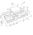
도 1은 일례로서 나타내는 설치 기초의 사시도이다.
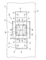
도 2는 설치 기초의 상면도이다.
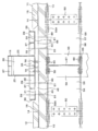
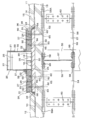
도 3은 도 1의 A-A선 단면도이다.
도 4는 금속 토대의 상면도이다.
도 5는 금속 토대의 측면도이다.
도 6은 설치 기초의 시공 순서의 일례를 나타내는 도이다.
도 7은 도 6으로부터 이어지는 설치 기초의 시공 순서를 나타내는 도이다.
도 8은 도 7로부터 이어지는 설치 기초의 시공 순서를 나타내는 도이다.
도 9는 도 8로부터 이어지는 설치 기초의 시공 순서를 나타내는 도이다.
도 10은 다른 일례로서 나타내는 설치 기초의 사시도이다.
도 11은 설치 기초의 상면도이다.
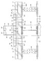
도 12는 도 10의 B-B선 단면도이다.
도 13은 금속 토대의 상면도이다.
도 14는 금속 토대의 측면도이다.
도 15는 설치 기초의 시공 순서의 일례를 나타내는 도이다.
도 16은 도 15로부터 이어지는 설치 기초의 시공 순서를 나타내는 도이다.
도 17은 도 15로부터 이어지는 설치 기초의 시공 순서를 나타내는 도이다.
도 18은 다른 일례로서 나타내는 설치 기초의 사시도이다.
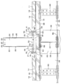
도 19는 도 1의 A-A선 단면도이다.
도 20은 금속 토대의 상면도이다.
도 21은 금속 토대의 측면도이다.
도 22는 도 18의 설치 기초의 시공 순서의 일례를 나타내는 도이다.
도 23은 도 22로부터 이어지는 설치 기초의 시공 순서를 나타내는 도이다.
도 24는 도 23으로부터 이어지는 설치 기초의 시공 순서를 나타내는 도이다.
도 25는 도 24로부터 이어지는 설치 기초의 시공 순서를 나타내는 도이다.1 is a perspective view of a mounting base shown as an example.
2 is a top view of the mounting foundation.
3 is a sectional view taken along the line AA in Fig.
4 is a top view of the metal foundation.
5 is a side view of the metal foundation.
It is a figure which shows an example of the construction procedure of a mounting foundation.
It is a figure which shows the construction procedure of the mounting foundation which continues from FIG.
It is a figure which shows the construction procedure of the installation foundation which continues from FIG.
It is a figure which shows the construction procedure of the installation foundation which continues from FIG.
It is a perspective view of the mounting base shown as another example.
11 is a top view of the mounting foundation.
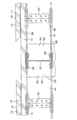
12 is a sectional view taken along line BB of Fig.
13 is a top view of the metal foundation.
14 is a side view of a metal foundation.
It is a figure which shows an example of the construction procedure of a mounting foundation.
It is a figure which shows the construction procedure of the installation foundation which continues from FIG.
It is a figure which shows the construction procedure of the mounting foundation which continues from FIG.
It is a perspective view of the mounting base shown as another example.
19 is a cross-sectional view taken along the line AA of FIG. 1.
20 is a top view of the metal foundation.
21 is a side view of the metal base.
It is a figure which shows an example of the construction procedure of the installation foundation of FIG.
It is a figure which shows the construction procedure of the mounting foundation which continues from FIG.
It is a figure which shows the construction procedure of the mounting foundation which continues from FIG.
It is a figure which shows the construction procedure of the installation foundation which continues from FIG.
일례로서 나타내는 설치 기초(10A)의 사시도인 도 1 등의 첨부의 도면을 참조하여 본 발명과 관련된 설치 기초의 상세를 설명하면 이하와 같다. 도 1에서는, 철골 구조물(11)에 설치된 1개의 설치 기초(10A)를 도시하고 있지만, 기초(10A)의 개수를 도시의 그것에 한정하는 것은 아니고, 일반적으로는 2개 이상의 기초(10A)가 철골 구조물(11)에 설치된다. 또한, 도 2는 설치 기초(10A)의 상면도이며, 도 3은 도 1의 A-A선 단면도이다. 도 4는 금속 토대(16)의 상면도이며, 도 5는 금속 토대(16)의 측면도이다. 도 1에서는 상하방향을 화살표 X1, 횡방향을 화살표 X2로 나타내고, 전후방향을 화살표 X3으로 나타낸다.With reference to the accompanying drawings, such as FIG. 1 which is a perspective view of the mounting
설치 기초(10A)는 신설 또는 기설의 철골 구조물(11)(철골 건물을 포함하는 모든 철골 건축물)의 옥상이나 지하의 소정의 설치 개소에 설치된다. 설치 개소는 옥상이나 지하의 철골 기둥과 철골 들보의 교차 개소에 시설된 슬라브이다. 여기서, 「슬라브」란 엄밀하게는 「마루판」을 의미하지만, 이 실시의 형태에서는, 철골 구조물(11)의 지하의 마루뿐만 아니라 옥상의 마루도 포함하는 의미로 이용한다.The
이 기초(10A)를 고정시키는 철골 구조물(11)은, 도 3에 나타내듯이, 철골 몸체(54)와, 몸체(54) 상에 시설된 콘크리트 마루(12)로 형성되어 있다. 철골 몸체(54)는 철골 기둥(55)과 철골 들보(beam)(56)로 형성되어 있다. 철골 기둥(55)이나 철골 들보(56)에는 웹(web)(57) 및 플랜지(flange)(58)를 가지는 H형강이 사용되고 있다. 철골 기둥(55)의 H형강(H-shaped steel)에는 콘크리트(59)가 타설되어 있다. 이들 H형강은 이들 플랜지(58)에 고정된 연결판(connecting plate)(60)을 통해 연결되어 있다. 또한, 철골 기둥(55)이나 철골 들보(56)에는 H형강 외에, 각형 강관이나 원형 강관, 산형강(山形鋼), 홈형강, C형강(C-shaped steel)의 어느 것을 사용할 수도 있다.The
콘크리트 마루(12)는 콘크리트 슬라브(13)와, 슬라브(13) 상에 시설된 방수층(14)과, 방수층(14) 상에 시설되는 누름 콘크리트(15)(모르타르층)로 형성되어 있다. 또한, 철골 구조물(11)이 지하에 구축된 경우, 방수층(14)과 누름 콘크리트(15)가 존재하지 않고, 슬라브(13)만으로 콘크리트 마루(12)를 형성하는 경우가 있다. 또, 슬라브(13)에는 도시는 하고 있지 않지만, 복수개의 철근이 매설되어 있다.The
설치 기초(10A)는 그것이 콘크리트 마루(12)로부터 누름 콘크리트(15)와 방수층(14)을 제거한 콘크리트 슬라브(13) 상에 설치된다. 설치 기초(10A)는 금속 토대(16)(토대) 및 금속 덮개(17)(덮개), 복수개의 높이 조절 볼트(18), 복수개의 지지 볼트(19), 모르타르(20)(시멘트 경화물), 방수층(21), 성형재(22)(프레임재)의 범용화(규격화)된 각 기초 구성부품을 이용하여 이들 기초 구성부품을 소정의 매뉴얼화된 순서로 조립하여 만들어져 있다.The mounting
철골 들보(56)를 형성하는 H형강의 상부 플랜지(58A)에는 지지 볼트(19)를 삽통하는 복수의 지지 볼트 삽통공(61)(볼트 구멍)이 만들어져 있다. 지지 볼트 삽통공(61)은 드릴에 의해 만들어지고, 콘크리트 슬라브(13)에 매설된 철근을 피한 상태로, H형강의 상부 플랜지(58A)를 상하방향으로 관통하고 있다. 이들 지지 볼트 삽통공(61)은 상부 플랜지(58A)에 있어서 횡방향과 전후방향으로 소정 간격으로 늘어서 있다. 상부 플랜지(58A)에는 지지 볼트 삽통공(61)이 8개 만들어져 있지만, 삽통공(61)의 개수에 특히 한정은 없고, 기초(10A)를 설치하기 전에 행하는 구조 계산(강도 계산)에 의해 그 개수가 결정된다.A plurality of support bolt insertion holes 61 (bolt holes) through which the
금속 토대(16)는 형상이나 치수가 동일한 규격화된 범용품이며, 복수개의 이들이 시공 현장 이외의 기초 부품 제조 공장에서 제조된 후, 시공 현장으로 반송된다. 금속 토대(16)는 콘크리트 마루(12)로부터 누름 콘크리트(15)와 방수층(14)을 제거한 콘크리트 슬라브(13) 상에 배치되어 있다. 금속 토대(16)는 중공 통상(筒狀)의 금속관(23)(관재)과 평면 형상이 대략 직사각형인 금속판(24)(저판)으로 형성되어 있다. 금속 토대(16)는 금속판(24)의 상면에 금속관(23)을 용접함으로써 제조된다. 금속관(23)이나 금속판(24)은 철이나 알루미늄, 합금 등의 금속으로 만들어져 있다.The
금속 토대(16)에서는 그것을 형성하는 금속관(23)(금속판(24)의 후기하는 제1부분(30)을 포함)이 철골 기둥(55)과 철골 들보(56)의 교차 개소에 시설된 콘크리트 슬라브(13)의 바로 위에 배치되고, 금속판(24)의 후기하는 제2부분(31)이 철골 들보(56)에 시설된 콘크리트 슬라브(13)의 바로 위에 배치되어 있다. 또한, 금속 토대(16)는 철근 콘크리트 기초와 비교하여 콘크리트가 생략되어 있는 분만큼 경량이다. 그러므로, 그 금속 토대(16)를 이용함으로써 기초(10A)의 중량을 큰 폭으로 경량화할 수가 있다.In the
금속관(23)은 대략 직사각형의 각 측판(25)을 가지고, 그 단면이 대략 사각형으로 성형되어 있다. 금속관(23)은 금속판(24)의 중앙부의 상면에 배치되고, 그 하단연이 금속판(24)의 상면에 용접에 의해 접합(융착)되어 있다. 금속관(23)에는 이들 측판(25)에 의해 중공 공간(26)이 획성되고, 금속관(23)의 정부에는 이들 측판(25)의 상단연(upper end edge)에 둘러싸여진 정부 개구(27)가 형성되어 있다. 금속관(23)의 정부에는 덮개 고정 볼트(28)를 나착하는 복수의 고정 볼트 나착공(29)이 만들어져 있다. 고정 볼트 나착공(29)에는 덮개 고정 볼트(28)가 나착하는 암나사(도시하지 않음)가 만들어져 있다.The
금속판(24)은 금속관(23)의 하단연으로부터 직경방향 내방(금속관(23)의 횡방향 내측)으로 뻗는 제1부분(30)과 금속관(23)의 하단연(lower end edge)으로부터 직경방향 외방(금속관(23)의 횡방향 외측)으로 뻗는 제2부분(31)을 가진다. 제1부분(30)에는 높이 조절 볼트(18)를 나착하는 복수의 조절 볼트 나착공(32)이 만들어져 있다(도 4 참조). 조절 볼트 나착공(32)에는 높이 조절 볼트(18)가 나착하는 암나사(도시하지 않음)가 만들어져 있다. 또한, 제1부분(30)에 있어서의 볼트 나착공(32)의 개수나 천공 개소에 특히 한정은 없고, 이들 볼트 나착공(32)를 제1부분(30)의 임의의 개소에 만들 수가 있다.The
금속판(24)의 제1부분(30)의 중앙부에는, 모르타르(20)를 충전하기 위한 타원형의 충전 구멍(33)이 만들어져 있다. 제1부분(30)의 네 귀퉁이에는, 모르타르(20)의 충전 상태를 확인하기 위한 확인 구멍(34)이 만들어져 있다(도 4 참조). 제1부분(30)에는 횡방향과 종방향으로 뻗는 복수의 보강판(35)이 설치되어 있다. 이들 보강판(35)은 금속관(23)의 내면과 금속판(24)의 상면에 용접에 의해 접합(융착)되어 있다. 보강판(35)은 금속관(23) 및 금속판(24)의 강도를 증가시키는 보강재로서 기능한다.An
금속판(24)의 제2부분(31)은 횡방향으로 뻗는 양쪽 단연(end edge)(주연)과 전후방향으로 뻗는 양쪽 측연(side edge)(주연)을 가진다. 제2부분(31)에는 그 양쪽 단연을 따라 단연으로부터 상방으로 기립하는 직사각형의 제1측판(36)이 용접에 의해 접합(융착)되고, 그 양쪽 측연을 따라 측연으로부터 상방으로 기립하는 직사각형의 제1측판(36)이 용접에 의해 접합(융착)되어 있다. 제2부분(31)(제1부분(30)을 포함)의 단연에 연접된 제1측판(36)은 서로 평행하게 횡방향으로 뻗어 있다. 제2부분(31)의 측연에 연접된 제1측판(36)은 서로 평행하게 전후방향으로 뻗어 있다.The
금속판(24)의 제2부분(31)에는 제1측판(36)의 사이에 위치하여 제2부분(31)으로부터 상방으로 기립하는 직사각형의 제2측판(37)이 용접에 의해 접합(융착)되어 있다. 제2측판(37)은 서로 평행하게 전후방향으로 뻗어 있다. 제1 및 제2측판(36, 37)은 금속판(24)의 제2부분(31)의 강도를 증가시키는 보강판으로서 기능한다. 금속 토대(16)에는 금속판(24)의 제2부분(31)과 제1측판(36)에 둘러싸여진 공간(38)이 획성되어 있다. 공간(38)에는 모르타르(20)(시멘트 경화물)가 충전되고, 그 모르타르(20)가 공간(38)에 있어서 경화하고 있다(도 3 참조). 또한, 도시는 하고 있지 않지만, 금속판(24)의 제2부분(31)의 상면에 금속제의 정판이 배치되고, 그 정판이 공간(38)의 개구를 폐색하고 있어도 좋다. 이 경우, 공간(38)에 모르타르(20)는 충전되지 않고, 정판이 제1 및 제2측판(36, 37)의 상단연에 용접에 의해 접합(융착)된다.The
금속판(24)의 제2부분(31)에는 지지 볼트(19)를 삽통하는 복수의 지지 볼트 삽통공(39)(볼트 구멍)이 만들어져 있다. 지지 볼트 삽통공(39)은 드릴에 의해 만들어지고, 금속판(24)의 제2부분(31)을 상하방향으로 관통하고 있다. 이들 지지 볼트 삽통공(39)은 제2부분(31)에 있어서 횡방향과 전후방향으로 소정 간격으로 늘어서 있다. 도 4에서는 지지 볼트 삽통공(39)이 8개 만들어져 있지만, 삽통공(39)의 개수에 특히 한정은 없고, 기초(10A)를 설치하기 전에 행하는 구조 계산(강도 계산)에 의해 그 개수가 결정된다.A plurality of support bolt insertion holes 39 (bolt holes) are formed in the
또한, 콘크리트 슬라브(13)의 기초 설치 위치에는 이들 지지 볼트(19)를 삽통하는 복수의 지지 볼트 삽통공(40)(볼트 구멍)이 만들어져 있다. 지지 볼트 삽통공(40)은 드릴에 의해 만들어지고, 콘크리트 슬라브(13)에 매설된 철근을 피한 상태로, 콘크리트 슬라브(13)를 상하방향으로 관통하고 있다. 지지 볼트 삽통공(40)은 금속 토대(16)를 콘크리트 슬라브(13)의 상면에 얹은 경우의, 금속판(24)의 제2부분(31)에 형성된 지지 볼트 삽통공(39)의 위치와 일치한다. 이들 지지 볼트 삽통공(40)은 콘크리트 슬라브(13)에 있어서 횡방향과 전후방향으로 소정 간격으로 늘어서 있다.Moreover, the some support bolt insertion hole 40 (bolt hole) which penetrates these
금속 덮개(17)는 형상이나 치수가 동일한 규격화된 범용품이며, 복수개의 이들이 시공 현장 이외의 기초 부품 제조 공장에서 제조된 후, 시공 현장으로 반송된다. 금속 덮개(17)는 철이나 알루미늄, 합금 등의 금속으로 만들어지고, 그 평면 형상이 대략 직사각형으로 성형되어 있다. 금속 덮개(17)의 하면에 있어서 덮개(17)의 주연의 내측에는 덮개(17)를 금속관(23)의 정부에 고정하기 위한 앵글재(41)(강재)가 용접에 의해 접합(융착)되어 있다. 금속 덮개(17)의 하면에 있어서 덮개(17)의 주연에는 물빼기 앵글재(42)(강재)가 용접에 의해 접합(융착)되어 있다. 앵글재(41)에는 덮개 고정 볼트(28)를 삽통하는 고정 볼트 삽통공(도시하지 않음)이 만들어지고, 그 고정 볼트 삽통공에 육각 너트(43)가 용접에 의해 접합(융착)되어 있다.The
금속 덮개(17)는 앵글재(41)에 만들어진 고정 볼트 삽통공에 삽통된 덮개 고정 볼트(28)와 앵글재(41)에 장착된 육각 너트(43)에 의해 금속관(24)의 정부에 고정되어 금속관(24)의 정부 개구(27)를 수밀(watertight)하게 폐색하고 있다. 금속 덮개(17)의 상면에는, 도시는 하고 있지 않지만, 태양 전지판이나 안테나, 저수조, 정화조, 공기조절 기기 등의 기계 기구, 철탑이나 철골 건설물 등의 건축물을 설치하기 위한 고정기구가 장착되어 있다.The
높이 조절 볼트(18)는 수나사(도시하지 않음)가 만들어진 축(44)과 볼트 헤드(45)로 형성된 육각 볼트이다. 높이 조절 볼트(18)의 축(44)은 금속판(24)의 제1부분(30)에 만들어진 조절 볼트 나착공(32)에 미리 나착되어 있다. 볼트 헤드(45)에 있어서 높이 조절 볼트(18)를 반시계방향으로 회전시키면, 볼트(18)의 축(44)이 볼트 나착공(32)의 하방으로 점차 나아감과 아울러, 제1부분(30)의 하면으로부터 하방으로 뻗어 나오고 볼트 헤드(45)가 콘크리트 기둥(13)의 상면에 맞닿는다. 이에 의해 금속 토대(16)를 콘크리트 슬라브(12)나 콘크리트 기둥(13)의 상면으로부터 상방으로 소정의 치수만큼 이간시킬 수가 있다. 반대로, 높이 조절 볼트(18)를 시계방향으로 회전시키면, 볼트(18)의 축(44)이 볼트 나착공(32)의 상방으로 점차 나아감과 아울러, 제1부분(30)의 하면으로부터 상방으로 뻗어 나온다. 이에 의해 금속 토대(16)를 콘크리트 슬라브(12)나 콘크리트 기둥(13)의 상면에 접근시킬 수가 있다.The
높이 조절 볼트(18)를 조절 볼트 나착공(32)에 있어서 회전시킴으로써 금속 토대(16)의 금속판(24)이 콘크리트 슬라브(12)나 콘크리트 기둥(13)의 상면으로부터 상방으로 이간하고, 슬라브(12)나 콘크리트 기둥(13)의 상면과 금속판(24)의 하면과의 사이에 소정의 높이 치수의 공간(46)이 형성된다. 금속 토대(16)의 금속판(24)의 제1부분(30)에 대한 이들 높이 조절 볼트(18)의 나착 위치를 조절함으로써, 공간(46)의 높이 치수를 조절할 수가 있고, 콘크리트 슬라브(12)나 콘크리트 기둥(13)의 상면으로부터의 금속 토대(16)의 높이 치수를 볼트(18)의 길이 한도로 조절할 수가 있다.By rotating the
지지 볼트(19)는 길이나 직경이 동일한 규격화된 범용품이며, 복수개의 이들이 시공 현장 이외의 기초 부품 제조 공장에서 제조된 후, 시공 현장으로 반송된다. 이들 볼트(19)는 강재로 만들어지고, 금속판(24)의 제2부분(31)에 만들어진 지지 볼트 삽통공(39)에 삽통되고, 콘크리트 슬라브(13)(콘크리트 마루)에 만들어진 지지 볼트 삽통공(40)에 삽통되고, 또한 H형강의 상부 플랜지(58A)에 만들어진 지지 볼트 삽통공(61)에 삽통되어 있다. 지지 볼트(19)는 콘크리트 슬라브(13)의 상면으로부터 상방으로 뻗는 제1고정 단부(47)와, H형강의 상부 플랜지(58A)로부터 하방으로 뻗는 제2고정 단부(48)와, 지지 볼트 삽통공(40, 61)에 위치하여 제1 및 제2고정 단부(47, 48)의 사이로 뻗는 중간부(49)를 가진다.The
지지 볼트(19)의 제1고정 단부(47)는 금속판(24)에 개구하는 지지 볼트 삽통공(39)에 삽통되고, 육각 이중 너트(50)(고정 수단)를 통해 금속판(24)에 고정되어 있다. 육각 이중 너트(50)는 제1고정 단부(47)의 금속판(24)으로부터 상방으로 뻗어 나오는 부분에 장착되어 있다. 지지 볼트(19)의 제2고정 단부(48)는 H형강의 상부 플랜지(58A)에 육각 이중 너트(51)(고정 수단)를 통해 고정되어 있다. 지지 볼트(19)의 이들 고정 단부(47, 48)에 육각 이중 너트(50, 51)을 나착하는 경우, 높이 조절 볼트(18)에 의해 콘크리트 슬라브(12)나 콘크리트 기둥(13)의 상면으로부터의 금속 토대(16)의 높이 치수가 이미 조절되어 있다.The first fixing
모르타르(20)는 콘크리트 슬라브(13)의 상면과 금속판(24)의 하면과의 사이에 형성된 공간(46)에 충전되어 있다. 모르타르(20)는 금속판(24)에 형성된 충전 구멍(33)으로부터 충전된다. 공간(46)에서는 거기에 충전된 모르타르(20)가 경화하고, 모르타르(20)가 콘크리트 슬라브(13)의 상면과 금속판(24)의 제1 및 제2부분(30, 31)의 하면에 접합되어 있음과 아울러, 지지 볼트(19)에 접합되어 있다.The
공간(46)에서는 지지 볼트(19)의 제1고정 단부(47) 중의 콘크리트 슬라브(13)의 상면과 금속판(24)의 제2부분(31)의 사이로 뻗는 부분이 모르타르(20)와 일체로 되어 있다. 경화한 모르타르(20)는 기초(10A) 상(금속 덮개(17) 상)에 태양 전지판이나 안테나, 저수조, 정화조, 공기조절 기기 등의 기계 기구, 철탑이나 철골 건설물 등의 건축물을 설치한 경우의 기초(10A)에 걸리는 하중을 지지 볼트(19)와 함께 분담한다. 또한, 공간(46)에 충전하는 시멘트 경화물에는 모르타르(20) 외에 콘크리트를 이용할 수도 있다.In the
금속관(23)과 금속판(24)의 교차부에는 삼각기둥 형상의 성형재(22)(프레임재)가 설치되어 있다. 성형재(22)는 금속관(23)이나 금속판(24)에 접착제(도시하지 않음)를 통해 고착되고, 금속관(23) 외주연 전역을 둘러싸고 있다. 누름 콘크리트(15)와 콘크리트 슬라브(13)에는 삼각기둥 형상의 성형재(22)(프레임재)가 설치되어 있다. 성형재(22)는 슬라브(13)나 누름 콘크리트(15)에 접착제(도시하지 않음)를 통해 고착되어 있다. 성형재(22)는 금속 토대(16)의 외주연(금속판(24)의 외주연)과 콘크리트 슬라브(13)(콘크리트 마루)의 사이에 설치되어 금속판(24)의 외주연 전역을 둘러싸고, 콘크리트 슬라브(13)와 금속판(24)의 외주연과의 사이의 공극을 폐색하고 있다.At the intersection of the
방수층(21)은 금속관(23)의 각 측판(25)의 외측에 설치되어 측판(25) 전역을 덮음과 아울러, 금속판(24)의 외측(공간(38)의 충전된 모르타르(20)의 상면, 또는 공간(38)을 폐색하는 정판의 상면)에 설치되어 금속판(24) 전역이나 제1 및 제2측판(36, 37) 전역을 덮고 있다. 방수층(21)에는 얇은 아스팔트 시트를 복수 중합하여 아스팔트 시트층을 만드는 아스팔트 방수가 이용되고 있다. 아스팔트 시트는 그 접착성에 의해 금속관(23)의 측판(25), 모르타르(20), 제1 및 제2측판(36, 37), 성형재(22)에 고착하고 있다. 방수층(21)의 금속판(24)의 제2부분(31)으로부터 외측으로 뻗는 부분(성형재(22)에 고착된 아스팔트 시트)은 철골 구조물(11)의 방수층(14)에 연결되어 있다. 또한, 방수층(21)으로서 아스팔트 방수 외에, 염화비닐 시트 방수나 고무 시트 방수, 우레탄 방수나 에폭시 방수, FRP 방수를 이용할 수도 있다.The
도 6은 설치 기초(10A)의 시공 순서의 일례를 나타내는 도이며, 도 7은 도 6으로부터 이어지는 설치 기초(10A)의 시공 순서를 나타내는 도이다. 도 8은 도 7로부터 이어지는 설치 기초(10A)의 시공 순서를 나타내는 도이며, 도 9는 도 8로부터 이어지는 설치 기초(10A)의 시공 순서를 나타내는 도이다. 도 6~도 9에서는 철골 구조물(11)을 단면으로서 나타내고, 일부를 제외한 기초(10A)의 각 부품을 단면으로서 나타낸다. 도 6~도 9를 참조하여 설치 기초(10A)를 철골 구조물(11)의 옥상에 설치하는 경우를 예로 하여 기초(10A)의 시공 순서를 설명하면 이하와 같다.FIG. 6: is a figure which shows an example of the construction procedure of 10 A of installation foundations, and FIG. 7 is a figure which shows the construction procedure of 10 A of installation foundations continued from FIG. FIG. 8: is a figure which shows the construction procedure of the
기초 부품 제조 공장에서 제조된 범용 부품화된 각 기초 부품(금속 토대(16)(토대), 금속 덮개(17)(덮개), 높이 조절 볼트(18), 지지 볼트(19), 방수층(21), 성형재(22)(프레임재))를 공장으로부터 시공 현장으로 반송한다. 또한, 기초 부품 제조 공장으로부터의 출하시에는, 금속판(24)의 제2부분(31)에 지지 볼트 삽통공(39)(볼트 구멍)이 만들어져 있지 않고, 시공 개소에 있어서 제2부분(31)에 지지 볼트 삽통공(39)을 천공한다. 또, 금속판(24)의 제1부분(30)에는 복수의 조절 볼트 나착공(32)이 기초 부품 제조 공장에 있어서 미리 만들어져 있고, 이들 볼트 나착공(32)에 높이 조절 볼트(18)가 나착되어 있다.Each generalized componentized foundation component manufactured by the basic component manufacturing plant (metal base 16 (base), metal cover 17 (cover),
옥상에 있어서의 철골 구조물(11)의 구성은, 도 6에 나타내듯이, 철골 기둥(55) 및 철골 들보(56)(철골 몸체(54))와, 콘크리트 슬라브(13)와, 슬라브(13) 상에 시설된 방수층(14)과, 방수층(14) 상에 시설되는 누름 콘크리트(15)로 형성되어 있다. 최초로, 철골 구조물(11)의 옥상에 있어서의 기초(10A)의 설치 개소를 위치 결정하고, 그 설치 개소(콘크리트 마루(12))에 마킹(marking)을 함과 아울러, 도 6에 나타내듯이, 그 설치 개소에 있어서, 콘크리트 마루(12)로부터 누름 콘크리트(15)와 방수층(14)을 제거하여 슬라브(13)를 노출시킨다.As shown in FIG. 6, the structure of the steel-
또한, 도시의 콘크리트 마루(12)는 콘크리트 슬라브(13)와 방수층(14)과 누름 콘크리트(15)로 형성되어 있지만, 콘크리트 마루(12)를 도시의 그것에 한정하는 것은 아니고, 현재 사용되고 있는 다른 구성의 콘크리트 마루 구조 모두에 이 설치 기초(10A)를 시공할 수가 있다. 예를 들어, 콘크리트 슬라브 상에 또한 합성수지를 도포하여 수지 피막을 형성한 콘크리트 마루 구조의 경우, 기초 설치 개소에서는, 콘크리트 마루로부터 수지 피막과 누름 콘크리트와 방수층을 제거하여 슬라브를 노출시킨다.In addition, although the
콘크리트 마루(12)로부터 콘크리트 슬라브(13)를 노출시킨 후 슬라브(13)의 내부에 설치된 철근의 위치를 센서를 이용하여 측정한다. 다음에, 이들 철근을 피하는 위치에 지지 볼트(19)를 설치하기 위해, 지지 볼트 삽통공(39)(볼트 구멍)의 철근을 피한 위치의 천공 개소를 금속판(24)의 제2부분(31)에 마킹한다. 마킹에 맞추어 드릴을 이용하여 금속판(24)의 제2부분(31)의 천공 개소에 지지 볼트 삽통공(39)을 천공한다(삽통공 볼트 구멍 천공 공정). 볼트 삽통공(39)을 천공한 후, 도 7에 나타내듯이, 슬라브(13)에 있어서의 기초 설치 개소의 마킹에 맞추어 그 설치 개소에 금속 토대(16)를 가설치한다(토대 가설치 공정).After exposing the
토대 가설치 공정에 있어서 금속 토대(16)를 가설치하면, 금속관(23) 및 금속판(24)의 제1부분(30)이 철골 기둥(55)과 철골 들보(56)의 교차 개소에 시설된 콘크리트 슬라브(13)의 바로 위에 위치하고, 금속판(24)의 제2부분(31)이 철골 들보(56)에 시설된 콘크리트 슬라브(13)의 바로 위에 위치함과 아울러, 높이 조절 볼트(18)의 볼트 헤드(45)가 콘크리트 슬라브(13)의 상면에 맞닿는다. 설치 개소에 금속 토대(16)를 가설치하면, 콘크리트 슬라브(13)의 상면에 맞닿는 이들 높이 조절 볼트(18)에 지탱되어 토대(16)가 슬라브(13)의 상면에 자립한다.When the
금속 토대(16)를 가설치한 후, 토대(16)의 금속판(24)의 제1부분(30)에 대한 이들 높이 조절 볼트(18)의 나착 위치를 조절하고, 콘크리트 슬라브(13)의 상면으로부터의 토대(16)의 설치 높이(높이 치수)(공간(46)의 높이 치수)를 조절한다(설치 높이 조절 공정). 설치 높이 조절 공정에서는, 높이 조절 볼트(18)의 설명에 있어서 말한 것처럼, 조절 볼트(18)를 조절 볼트 나착공(32)에 있어서 시계방향과 반시계방향의 어느 쪽인가로 회전시키고, 금속 토대(16)의 콘크리트 슬라브(13)의 상면으로부터의 이간 치수를 조절한다.After provision of the
설치 기초(10A)는 높이 조절 볼트(18)를 이용함으로써 기초(10A)의 시공중에 금속 토대(16)의 높이 치수를 자유롭게 바꿀 수가 있어 기초(10A)의 높이 치수의 변경 요구에 즉석에서 대응할 수가 있다. 설치 기초(10A)는 복수개의 이들을 설치하는 경우에 이들 기초(10A)끼리의 높이 치수를 용이하게 조절할 수가 있어 이들 기초(10A)의 높이 치수를 균일하게 갖출 수가 있다.The
금속 토대(16)의 높이 치수를 조절한 후, 금속판(24)의 지지 볼트 삽통공(39)의 위치에 맞추어 콘크리트 슬라브(13)의 지지 볼트 삽통공(40)(볼트 구멍)의 천공 개소에 마킹을 한다. 다음에, 가설치 개소(설치 개소)로부터 금속 토대(16)를 일시적으로 치운 후, 드릴을 이용하여 마킹한 천공 개소에 지지 볼트 삽통공(40)을 천공함과 아울러(볼트 구멍 천공 공정), 지지 볼트 삽통공(39)의 위치에 맞추어 H형강의 상부 플랜지(58A)에 지지 볼트 삽통공(61)을 천공한다(볼트 구멍 천공 공정). 콘크리트 슬라브(13)나 상부 플랜지(58A)에 지지 볼트 삽통공(40, 61)을 만든 후, 도 8에 나타내듯이, 금속판(24)의 제2부분(31)에 만들어진 지지 볼트 삽통공(39)에 지지 볼트(19)를 삽통하고, 슬라브(13)에 만들어진 지지 볼트 삽통공(40)에 볼트(19)를 삽통함과 아울러, 상부 플랜지(58A)에 만들어진 지지 볼트 삽통공(61)에 볼트(19)를 삽통한다.After adjusting the height dimension of the
지지 볼트(19)를 지지 볼트 삽통공(39, 40, 61)에 삽통하면, 제1고정 단부(47)가 콘크리트 슬라브(13)의 상면으로부터 상방으로 뻗어 나오고, 제2고정 단부(48)가 상부 플랜지(58A)로부터 하방으로 뻗어 나옴과 아울러, 중간부(49)가 지지 볼트 삽통공(40, 61)에 위치한다. 다음에, 지지 볼트(19)의 제1고정 단부(47) 중의 금속판(24)으로부터 상방으로 뻗어 나오는 부분에 육각 이중 너트(50)를 나착함과 아울러, 지지 볼트(19)의 제2고정 단부(48)에 육각 이중 너트(51)를 나착하고, 지지 볼트(19)를 금속판(24)과 H형강의 상부 플랜지(58A)에 고정한다(지지 볼트 고정 공정).When the
지지 볼트(19)를 금속판(24)과 상부 플랜지(58A)에 고정한 후, 도 9에 나타내듯이, 금속판(24)의 제2부분(31)과 제1측판(36)에 둘러싸여진 공간(38)에 모르타르(20)(시멘트 경화물)를 충전하고, 모르타르(20)를 양생시킨다. 또한, 모르타르(20)의 양생기간을 제거하기 위해, 도시는 하고 있지 않지만, 모르타르(20)의 충전에 대신하여 금속판(24)의 제2부분(31)의 상면에 금속제의 정판을 배치하고, 그 정판에 의해 공간(38)의 정부 개구를 폐색한다. 이 경우, 공간(38)에 모르타르(20)는 충전하지 않고, 정판을 제1 및 제2측판(36, 37)의 상단연에 용접에 의해 접합(융착)한다.After fixing the
모르타르(20)가 경화한 후(양생한 후), 또는 정판으로 공간(38)의 정부 개구를 폐색한 후, 금속관(23)과 금속판(24)의 교차부에 삼각기둥 형상의 성형재(22)를 설치하고, 그 성형재(22)를 금속관(23)과 금속판(24)에 접착제(도시하지 않음)를 통해 고착한다. 또한, 누름 콘크리트(15)와 콘크리트 슬라브(13)에 삼각기둥 형상의 성형재(22)를 설치하고, 그 성형재(22)를 누름 콘크리트(15)와 슬라브(13)에 접착제(도시하지 않음)를 통해 고착한다(프레임재 설치 공정). 금속관(23)과 금속판(24)의 교차부에 성형재(22)를 설치하면, 성형재(22)가 금속관(23)의 외주연 전역을 둘러싼다. 누름 콘크리트(15)와 콘크리트 슬라브(13)에 성형재(22)를 설치하면, 성형재(22)가 금속판(24)의 외주연 전역을 둘러싸고, 성형재(22)가 콘크리트 슬라브(13)와 금속판(24)의 외주연과의 사이의 공극을 폐색한다.After the
성형재(22)를 설치한 후, 금속관(23)의 각 측판(25)의 외측과 금속판(24)의 외측(공간(38)의 충전된 모르타르(20)의 상면, 또는 공간(38)을 폐색하는 정판의 상면)에 방수층(21)을 설치한다(방수층 설치 공정). 방수층 설치 공정에서는, 복수의 얇은 아스팔트 시트를 금속관(23)의 각 측판(25)의 외측과 금속판(24)의 외측과 성형재(22)의 외측에 고착하여 방수층(21)을 만듦과 아울러, 성형재(22)로부터 뻗는 방수층(21)을 콘크리트 마루(12)의 방수층(14)에 연결한다. 설치 기초(10A)는 그것이 철골 구조물(11)의 옥외에 설치된 경우에서도 방수층(21)에 의해 금속 토대(16)에의 물의 침입을 방지할 수가 있고, 토대(16)에 물이 진입하는 것에 의한 토대(16)의 부식이나 강도 저하를 방지할 수가 있다. 또, 콘크리트 마루(12)(슬라브(13))로의 물의 진입을 방지할 수가 있고, 물의 진입에 의한 콘크리트 마루(12)나 철골 구조물(11)의 열화를 방지할 수가 있다.After the
방수층(21)을 설치한 후, 콘크리트 슬라브(13)의 상면과 금속판(24)의 하면과의 사이에 형성된 공간(46)에 모르타르(20)(시멘트 경화물)를 충전한다(시멘트 경화물 충전 공정). 시멘트 경화물 충전 공정에서는, 확인 구멍(34)으로부터 공간(46)에 있어서의 모르타르(20)의 충전 상태를 확인하면서, 충전 구멍(33)으로부터 공간(46)에 모르타르(20)를 충전한다.After installing the
설치 기초(10A)는 지지 볼트(19)를 금속판(24)이나 상부 플랜지(58A)에 고정한 후에 충전 구멍(33)을 이용하여 공간(46)에 모르타르(20)를 충전할 수가 있기 때문에, 공간(46)에 모르타르(20)를 확실하게 충전할 수가 있다. 설치 기초(10A)는 확인 구멍(34)을 이용하여 공간(46)에 충전된 모르타르(20)의 충전 상태를 확인함으로써, 모르타르(20)가 공간(46)에 치우쳐 충전되는 일이 없어 모르타르(20)를 공간(46) 전역에 치우침이 없이 충전할 수가 있다.Since the mounting
공간(46)에 모르타르(20)를 충전한 직후, 모르타르(20)의 양생기간을 기다리는 일이 없이, 즉시 금속관(23)의 정부에 금속 덮개(17)를 끼워넣어 금속관(23)의 정부 개구(27)를 폐색한다. 금속관(23)의 정부에 금속 덮개(17)를 끼워넣은 후, 금속관(23)의 각 측판(25)의 상부에 만들어진 고정 볼트 나착공(29)에 덮개 고정 볼트(28)를 나착함과 아울러, 금속 덮개(17)의 앵글재(41)의 덮개 고정 볼트 삽통공에 볼트(29)를 삽통하고, 볼트 삽통공에 장착된 육각 너트(43)에 볼트(29)를 나착하여 덮개(17)를 금속관(23)의 정부에 고정한다(정부 폐쇄 공정)(도 3 원용). 금속관(23)의 정부 개구(27)는 금속 덮개(17)에 의해 수밀하게 폐색된다.Immediately after the
또한, 공극(공간(46)의 주연)이 성형재(22)에 의해 폐색되어 있기 때문에, 성형재(22)가 경화전의 모르타르(20)의 누설을 방지하는 제방으로 되어, 공간(46)에 충전된 모르타르(20)가 공극(공간(46))으로부터 누출되는 일은 없고, 모르타르(20)의 충전 후에 즉시 금속 덮개(17)로 정부 개구(27)를 폐색할 수가 있다. 설치 기초(10A)에서는 금속관(23)의 정부에 금속 덮개(17)를 끼워넣은(고정한) 직후로서 공간(46)에 충전된 모르타르(20)가 미경화 상태에 있고, 금속관(23)의 정부에 덮개(17)를 고정한 후로부터 모르타르(20)의 양생기간이 개시된다.In addition, since the voids (periphery of the space 46) are closed by the
공간(46)에서는 모르타르(20)의 양생기간이 경과하고, 거기에 충전된 모르타르(20)가 경화함으로써, 지지 볼트(19)의 제1고정 단부(47) 중의 콘크리트 기둥(13)(콘크리트 몸체(13))의 상면과 금속관(23)의 금속판(24)의 사이로 뻗는 부분(볼트(19)의 제1고정 단부(47) 중의 금속판(24)의 하면으로부터 하방으로 노출되는 부분)이 모르타르(20)와 일체로 되어 철근 모르타르를 형성한다.In the
이상의 각 공정이 종료하면, 도 1~3에 나타내는 설치 기초(10A)가 완성된다. 설치 기초(10A)는 모르타르(20)를 공간(46)에 충전한 후, 모르타르(20)의 양생기간을 기다리는 일이 없이, 즉시 금속관(23)의 정부 개구(27)를 금속 덮개(17)에 의해 폐색하여, 기초(10A)를 완성시킬 수가 있기 때문에, 공간(46)에 충전한 모르타르(20)의 양생기간분만큼 시공기간을 단축할 수가 있어 양생기간을 기다리는 일이 없이 복수의 기초(10A)의 시공을 병행하여 행할 수가 있다.When each above process is complete | finished, the
설치 기초(10A)는 복수개의 지지 볼트(19)를 경량인 금속 토대(16)의 금속판(24)의 제2부분(31)과 철골 들보(56)(H형강의 상부 플랜지(58A))에 고정하고, 공간(46)에 모르타르(20)를 충전함과 아울러, 금속관(23)의 정부에 금속 덮개(17)를 고정하는 것만으로 기초(10A)를 구축할 수가 있고, 이들이 모두 범용 부품화되어 유닛 시스템으로서 조립할 수 있기 때문에, 거푸집의 제작이나 모르타르의 양생에 드는 수고나 비용, 시간을 덜 수가 있음과 아울러, 시공 작업을 간략화할 수가 있어 그 만큼의 시공기간을 큰 폭으로 단축할 수가 있다.The mounting
설치 기초(10A)는 그 설치 개소가 기설의 철골 구조물(11)의 옥상이나 지하에 방수 기능을 시설한 방수층을 구비한 슬라브(13)인 경우에서도, 설치 개소의 방수층(14)을 제거한 후의 노출한 슬라브(13)에 기초(10A)를 설치하고, 기초(10A)를 설치한 직후에 설치 개소 근방의 방수층을 보수(새로운 방수층(21)을 시설)할 수가 있기 때문에, 기초(10A)를 신속하게 설치할 수가 있어 기초(10A)의 설치에 필요로 하는 시간을 큰 폭으로 단축할 수가 있다.10 A of installation foundations are exposed after removing the
설치 기초(10A)는 지지 볼트(19)의 제1고정 단부(47)가 금속판(24)의 제2부분(31)에 고정되고, 지지 볼트(19)의 제2고정 단부(48)가 철골 들보(56)(H형강의 상부 플랜지(58A))에 고정되기 때문에, 그것을 철골 구조물(11)에 강고하게 고정시킬 수가 있어 태양 전지판이나 안테나, 저수조, 정화조, 공기조절 기기 등의 기계 기구, 철탑이나 철골 건설물 등의 건축물을 강고하게 설치할 수가 있다. 설치 기초(10A)는 콘크리트 슬라브(13)의 상면과 금속판(24)의 하면과의 사이의 공간(46)에 모르타르(20)가 충전되고, 기초(10A) 상에 기계 기기나 건축물을 설치한 경우의 기초(10A)에 걸리는 하중을 지지 볼트(19)와 모르타르(20)로 분담하기 때문에, 기초(10A)에 걸리는 하중으로 그것이 의도하지 않게 경사지거나 기초(10A)가 붕괴되는 일이 없이 기계 기기나 건축물을 확실하게 지지할 수가 있다.The mounting
도 10은 다른 일례로서 나타내는 설치 기초(10B)의 사시도이며, 도 11은 설치 기초(10B)의 상면도이다. 도 12는 도 10의 B-B선 단면도이며, 도 13은 금속 토대(16)의 상면도이다. 도 14는 금속 토대(16)의 측면도이다. 도 10에서는 상하방향을 화살표 X1, 횡방향을 화살표 X2로 나타내고, 전후방향을 화살표 X3으로 나타낸다.FIG. 10: is a perspective view of the mounting
이 설치 기초(10B)가 도 1의 그것과 다른 바는 지지 볼트(19)에 대신해 앵커 볼트(62)가 사용되고, 그 앵커 볼트(62)가 콘크리트 슬라브(13)에 만들어진 앵커홀(63)에 고정되어 있는 점, 철골 들보(56)를 형성하는 H형강의 상부 플랜지(58A)에 지지 볼트 삽통공(61)이 만들어지지 않은 점에 있다. 또한, 이 기초(10B)의 그 외의 구성은, 도 1의 기초(10A)의 구성과 동일하므로 도 1의 기초(10A)와 동일한 부호를 붙임과 아울러, 도 1의 기초(10A)의 설명을 원용함으로써, 이 기초(10B)에 있어서의 그 외의 구성의 상세한 설명은 생략한다.This mounting
설치 기초(10B)는 도 1의 그것과 마찬가지로 콘크리트 마루(12)로부터 누름 콘크리트(15)(모르타르층)와 방수층(14)을 제거한 콘크리트 슬라브(13) 상에 설치된다. 설치 기초(10B)는 금속 토대(16)(토대) 및 금속 덮개(17)(덮개), 복수개의 높이 조절 볼트(18), 복수개의 앵커 볼트(62), 모르타르(20), 방수층(21), 성형재(22)(프레임재)의 범용화(규격화)된 각 기초 구성부품을 소정의 순서로 조립하여 만들어져 있다.The mounting
금속 토대(16)는 콘크리트 마루(12)로부터 누름 콘크리트(15)와 방수층(14)을 제거한 콘크리트 슬라브(13) 상에 배치되어 있다. 금속 토대(16)는 금속관(23)과 금속판(24)으로 형성되어 있다. 금속관(23)(금속판(24)의 제1부분(30)을 포함)은 철골 기둥(55)과 철골 들보(56)의 교차 개소에 시설된 콘크리트 슬라브(13)의 바로 위에 배치되고, 금속판(24)의 제2부분(31)은 철골 들보(56)에 시설된 콘크리트 슬라브(13)의 바로 위에 배치되어 있다. 금속관(23)은 도 1의 기초(10A)의 그것과 동일하다. 또한, 금속 토대(16)는 콘크리트가 생략되어 있는 분만큼 경량이며, 그 토대(16)를 이용함으로써 기초(10B)의 중량을 큰 폭으로 경량화할 수가 있다.The
금속판(24)은 금속관(23)의 하단연으로부터 직경방향 내방으로 뻗는 제1부분(30)과 금속관(23)의 하단연으로부터 직경방향 외방으로 뻗는 제2부분(31)을 가진다. 제1부분(30)에는 높이 조절 볼트(18)를 나착하는 복수의 조절 볼트 나착공(32)이 만들어져 있다(도 13 참조). 제1부분(30)의 중앙부에는, 모르타르(20)를 충전하기 위한 타원형의 충전 구멍(33)이 만들어지고, 제1부분(30)의 네 귀퉁이에는, 모르타르(20)의 충전 상태를 확인하기 위한 확인 구멍(34)이 만들어져 있다(도 13 참조). 제1부분(30)에는 횡방향과 종방향으로 뻗는 복수의 보강판(35)이 설치되어 있다.The
금속판(24)의 제2부분(31)에는 그 양쪽 단연(end edge)을 따라 단연으로부터 상방으로 기립하는 제1측판(36)이 설치되고, 그 양쪽 측연을 따라 측연으로부터 상방으로 기립하는 제1측판(36)이 설치되어 있다. 또한, 제1측판(36)의 사이에 위치하여 제2부분(31)으로부터 상방으로 기립하는 제2측판(37)이 설치되어 있다. 금속판(24)의 제2부분(31)과 제1측판(36)에 둘러싸여진 공간(38)에는 모르타르(20)(시멘트 경화물)가 충전되고, 그 모르타르(20)가 공간(38)에 있어서 경화하고 있다(도 12 참조). 또한, 도 1의 기초(10A)와 마찬가지로 금속판(24)의 제2부분(31)의 상면에 금속제의 정판이 배치되고, 그 정판이 공간(38)의 개구를 폐색하고 있어도 좋다.The
금속판(24)의 제2부분(31)에는 앵커 볼트(62)를 삽통하는 복수의 앵커 볼트 삽통공(39)(볼트 구멍)이 만들어져 있다. 이들 앵커 볼트 삽통공(39)은 제2부분(31)에 있어서 횡방향과 전후방향으로 소정 간격으로 늘어서 있다. 또한, 콘크리트 슬라브(13)의 기초 설치 위치에는 이들 앵커 볼트(62)를 고정하는 복수의 앵커홀(63)이 만들어져 있다. 앵커홀(63)은 드릴에 의해 만들어지고, 콘크리트 슬라브(13)에 매설된 철근을 피한 상태로, 슬라브(13)의 상면으로부터 하면을 향해 상하방향으로 뻗어 H형강의 상부 플랜지(58A) 근방에 이르고 있다. 앵커홀(63)은 금속 토대(16)를 콘크리트 슬라브(13)의 상면에 얹은 경우의, 금속판(24)의 제2부분(31)에 형성된 앵커 볼트 삽통공(39)의 위치와 일치한다. 이들 앵커홀(63)은 콘크리트 슬라브(13)에 있어서 횡방향과 전후방향으로 소정 간격으로 늘어서 있다.A plurality of anchor bolt insertion holes 39 (bolt holes) through which the
금속 덮개(17)나 높이 조절 볼트(18)는 도 1의 기초(10A)의 그것들과 동일하다. 금속 덮개(17)는 도 1의 그것과 마찬가지로 앵글재(41)에 만들어진 고정 볼트 삽통공에 삽통된 덮개 고정 볼트(28)와 앵글재(41)에 장착된 육각 너트(43)에 의해 금속관(24)의 정부에 고정되어 금속관(24)의 정부 개구를 수밀(watertight)하게 폐색하고 있다.The
높이 조절 볼트(18)는 도 1의 그것과 마찬가지로 그것을 조절 볼트 나착공(32)에 있어서 회전시킴으로써 금속 토대(16)의 금속판(24)이 콘크리트 슬라브(13)의 상면으로부터 상방으로 이간하고, 슬라브(13)의 상면과 금속판(24)의 하면과의 사이에 소정의 높이 치수의 공간(46)이 형성된다. 금속 토대(16)의 금속판(24)의 제1부분(30)에 대한 이들 높이 조절 볼트(18)의 나착 위치를 조절함으로써, 공간(46)의 높이 치수를 조절할 수가 있고, 콘크리트 슬라브(13)의 상면으로부터의 금속 토대(16)의 높이 치수를 볼트(18)의 길이 한도로 조절할 수가 있다.The
앵커 볼트(62)는 길이나 직경이 동일한 규격화된 범용품이며, 복수개의 이들이 시공 현장 이외의 기초 부품 제조 공장에서 제조된다. 앵커 볼트(62) 강재로 만들어지고, 금속판(24)의 제2부분(31)에 만들어진 앵커 볼트 삽통공(39)에 삽통되고, 또한 콘크리트 슬라브(13)에 만들어진 앵커홀(63)에 삽입되어 있다. 이들 앵커 볼트(62) 콘크리트 슬라브(13)의 상면으로부터 상방으로 뻗는 제1고정 단부(64)와 앵커홀(63)에 삽입되어 홀(63)에 고정된 제2고정 단부(65)를 가진다. 앵커 볼트(62)의 이들 단부(64, 65)에는 수나사(도시하지 않음)가 만들어져 있다.The
앵커 볼트(62)의 제2고정 단부(65)는 그 주위면이 앵커홀(63)에 수지 접착제를 통해 고정되어 있다. 앵커 볼트(62)의 제1고정 단부(64)는 앵커 볼트 삽통공(39)에 삽통되고, 제1고정 단부(64) 중의 금속판(24)의 상면으로부터 상방으로 노출되는 부분에는 육각 이중 너트(50)가 나착되어 있다. 앵커 볼트(62)의 제1고정 단부(64)는 육각 이중 너트(50)(고정 수단)를 통해 금속판(24)에 고정되어 있다. 앵커 볼트(62)의 고정 단부(64)에 육각 이중 너트(50)를 나착하는 경우, 높이 조절 볼트(18)에 의해 콘크리트 슬라브(13)의 상면으로부터의 금속 토대(16)의 높이 치수가 이미 조절되어 있다.The second
모르타르(20)는 금속판(24)에 형성된 충전 구멍(33)으로부터 공간(46)에 충전되어 있다. 공간(46)에서는 거기에 충전된 모르타르(20)가 경화하고, 모르타르(20)가 콘크리트 슬라브(13)의 상면과 금속판(24)의 제1 및 제2부분(30, 31)의 하면에 접합되어 있음과 아울러, 앵커 볼트(62)에 접합되어 있다. 공간(46)에서는 앵커 볼트(62)의 제1고정 단부(64) 중의 콘크리트 슬라브(13)의 상면과 금속판(24)의 제2부분(31)의 사이로 뻗는 부분이 모르타르(20)와 일체로 되어 있다. 경화한 모르타르(20)는 기초(10A) 상(금속 덮개(17) 상)에 태양 전지판이나 안테나, 저수조, 정화조, 공기조절 기기 등의 기계 기구, 철탑이나 철골 건설물 등의 건축물을 설치한 경우의 기초(10A)에 걸리는 하중을 앵커 볼트(62)와 함께 분담한다.The
금속관(23)과 금속판(24)의 교차부에는 삼각기둥 형상의 성형재(22)(프레임재)가 설치되어 있다. 성형재(22)는 금속관(23)이나 금속판(24)에 접착제(도시하지 않음)를 통해 고착되고, 금속관(23)의 외주연 전역을 둘러싸고 있다. 누름 콘크리트(15)와 콘크리트 슬라브(13)에는 삼각기둥 형상의 성형재(22)(프레임재)가 설치되어 있다. 성형재(22)는 슬라브(13)나 누름 콘크리트(15)에 접착제(도시하지 않음)를 통해 고착되어 있다. 성형재(22)는 금속 토대(16)의 외주연(금속판(24)의 외주연)과 콘크리트 슬라브(13)(콘크리트 구조물)와의 사이에 설치되어 금속판(24)의 외주연 전역을 둘러싸고, 슬라브(13)와 금속판(24)의 외주연과의 사이의 공극을 폐색하고 있다.At the intersection of the
방수층(21)은 금속관(23)의 각 측판(25)의 외측에 설치되어 측판(25) 전역을 덮음과 아울러, 금속판(24)의 외측(공간(38)의 충전된 모르타르(20)의 상면, 또는 공간(38)을 폐색하는 정판의 상면)에 설치되어 금속판(24) 전역이나 제1 및 제2측판(36, 37) 전역을 덮고 있다. 방수층(21)에는 얇은 아스팔트 시트를 복수 중합하여 아스팔트 시트층을 만드는 아스팔트 방수가 이용되고 있다. 아스팔트 시트는 그 접착성에 의해 금속관(23)의 측판(25), 모르타르(20), 제1 및 제2측판(36, 37), 성형재(22)에 고착하고 있다. 방수층(21)의 금속판(24)의 제2부분(31)으로부터 외측으로 뻗는 부분(성형재(22)에 고착된 아스팔트 시트)은 콘크리트 마루(12)의 방수층(14)에 연결되어 있다.The
도 15는 설치 기초(10B)의 시공 순서의 일례를 나타내는 도이며, 도 16은 도 15로부터 이어지는 설치 기초(10B)의 시공 순서를 나타내는 도이다. 도 17은 도 15로부터 이어지는 설치 기초(10B)의 시공 순서를 나타내는 도이다. 도 15~도 17에서는 철골 구조물(11)을 단면으로서 나타내고, 일부를 제외한 기초(10B)의 각 부품을 단면으로서 나타낸다.FIG. 15: is a figure which shows an example of the construction procedure of the
도 6을 원용함과 아울러 도 15~도 17을 참조하여 설치 기초(10B)를 철골 구조물(11)의 옥상에 설치하는 경우를 예로 하여 설치 기초(10B)의 시공 순서를 설명하면 이하와 같다. 또한, 기초 부품 제조 공장으로부터의 출하시에는, 금속판(24)의 제2부분(31)에 지지 볼트 삽통공(39)(볼트 구멍)이 만들어져 있지 않고, 시공 개소에 있어서 제2부분(31)에 지지 볼트 삽통공(39)을 천공한다. 또, 금속판(24)의 제1부분(30)에는 복수의 조절 볼트 나착공(32)이 기초 부품 제조 공장에 있어서 미리 만들어져 있고, 이들 볼트 나착공(32)에 높이 조절 볼트(18)가 나착되어 있다.Referring to FIG. 6 and referring to FIGS. 15 to 17, the construction procedure of the
기초 부품 제조 공장에서 제조된 범용 부품화된 각 기초 부품(금속 토대(16)(토대), 금속 덮개(17)(덮개), 높이 조절 볼트(18), 앵커 볼트(62), 방수층(21), 성형재(22)(프레임재))를 공장으로부터 시공 현장으로 반송한 후, 철골 구조물(11)의 옥상에 있어서의 기초(10B)의 설치 개소를 위치 결정하고, 그 설치 개소에 마킹을 한다. 다음에, 그 설치 개소에 있어서, 콘크리트 마루(12)로부터 누름 콘크리트(15)와 방수층(14)을 제거하여 콘크리트 슬라브(13)를 노출시킨다(도 6 원용).Each generalized componentized foundation component manufactured by the basic component manufacturing plant (metal base 16 (base), metal cover 17 (cover),
콘크리트 구조물(11)로부터 콘크리트 슬라브(13)를 노출시킨 후, 슬라브(13)의 내부에 설치된 철근의 위치를 센서를 이용하여 측정한다. 다음에, 이들 철근을 피하는 위치에 지지 볼트(19)를 설치하기 위해, 지지 볼트 삽통공(39)(볼트 구멍)의 철근을 피한 위치의 천공 개소를 금속판(24)의 제2부분(31)에 마킹한다. 마킹에 맞추어 드릴을 이용하여 금속판(24)의 제2부분(31)의 천공 개소에 지지 볼트 삽통공(39)을 천공한다(삽통공 볼트 구멍 천공 공정). 볼트 삽통공(39)을 천공한 후, 도 15에 나타내듯이, 슬라브(13)에 있어서의 기초 설치 개소의 마킹에 맞추어 그 설치 개소에 금속 토대(16)를 가설치한다(토대 가설치 공정).After exposing the
토대 가설치 공정에 있어서 금속 토대(16)를 가설치하면, 금속관(23) 및 금속판(24)의 제1부분(30)이 철골 기둥(55)과 철골 들보(56)의 교차 개소에 시설된 콘크리트 슬라브(13)의 바로 위에 위치하고, 금속판(24)의 제2부분(31)이 철골 들보(56)에 시설된 콘크리트 슬라브(13)의 바로 위에 위치함과 아울러, 높이 조절 볼트(18)의 볼트 헤드(45)가 콘크리트 슬라브(13)의 상면에 맞닿는다. 설치 개소에 금속 토대(16)를 가설치하면, 콘크리트 슬라브(13)의 상면에 맞닿는 높이 조절 볼트(18)에 지탱되어 토대(16)가 슬라브(13)의 상면에 자립한다.When the
금속 토대(16)를 가설치한 후, 토대(16)의 금속판(24)의 제1부분(30)에 대한 이들 높이 조절 볼트(18)의 나착 위치를 조절하고, 콘크리트 슬라브(13)의 상면으로부터의 토대(16)의 설치 높이(높이 치수)(공간(46)의 높이 치수)를 조절한다(설치 높이 조절 공정). 설치 기초(10B)는 높이 조절 볼트(18)를 이용함으로써 기초(10B)의 시공중에 금속 토대(16)의 높이 치수를 자유롭게 바꿀 수가 있어 기초(10B)의 높이 치수의 변경 요구에 즉석에서 대응할 수가 있다. 설치 기초(10B)는 복수개의 이들을 설치하는 경우에 이들 기초(10B)끼리의 높이 치수를 용이하게 조절할 수가 있어 이들 기초(10B)의 높이 치수를 균일하게 갖출 수가 있다.After provision of the
금속 토대(16)의 높이 치수를 조절한 후, 금속판(24)의 지지 볼트 삽통공(39)의 위치에 맞추어 콘크리트 슬라브(13)의 지지 볼트 삽통공(40)(볼트 구멍)의 천공 개소에 마킹을 한다. 다음에, 가설치 개소(설치 개소)로부터 금속 토대(16)를 일시적으로 치운 후, 드릴을 이용하여 마킹한 천공 개소에 지지 볼트 삽통공(40)을 천공한다(삽통공 천공 공정). 콘크리트 슬라브(13)에 지지 볼트 삽통공(40)을 만든 후, 금속 토대(16)를 설치 개소에 다시 가설치하고, 도 16에 나타내듯이, 금속판(24)의 제2부분(31)에 만들어진 지지 볼트 삽통공(39)에 지지 볼트(19)를 삽통함과 아울러, 슬라브(13)에 만들어진 지지 볼트 삽통공(40)에 지지 볼트(19)를 삽통한다.After adjusting the height dimension of the
앵커 볼트(62)를 삽통공(39)에 삽통하고, 앵커홀(63)에 삽입하면, 제1고정 단부(64)가 콘크리트 슬라브(13)의 상면으로부터 상방으로 뻗어 나오고, 제2고정 단부(65)가 앵커홀(63)에 위치한다. 앵커 볼트(62)의 제2고정 단부(65)는 그 주위면이 앵커홀(63)에 수지 접착제를 통해 고정된다. 다음에, 앵커 볼트(62)의 제1고정 단부(64) 중의 금속판(24)으로부터 상방으로 뻗어 나오는 부분에 육각 이중 너트(50)를 나착하고, 앵커 볼트(62)를 금속판(24)과 콘크리트 슬라브(13)에 고정한다(지지 볼트 고정 공정).When the
앵커 볼트(62)를 금속판(24)과 콘크리트 슬라브(13)에 고정한 후, 도 17에 나타내듯이, 금속판(24)의 제2부분(31)과 제1측판(36)에 둘러싸여진 공간(38)에 모르타르(20)를 충전하고, 모르타르(20)를 양생시킨다. 또한, 도 1의 기초(10A)와 마찬가지로 모르타르(20)의 충전에 대신하여 금속판(24)의 제2부분(31)의 상면에 금속제의 정판을 배치하고, 그 정판에 의해 공간(38)의 정부 개구를 폐색해도 좋다.After fixing the
모르타르(20)가 경화한 후, 또는 정판으로 공간(38)의 정부 개구를 폐색한 후, 금속관(23)과 금속판(24)의 교차부에 삼각기둥 형상의 성형재(22)를 설치함과 아울러, 누름 콘크리트(15)와 콘크리트 슬라브(13)에 삼각기둥 형상의 성형재(22)를 설치한다(프레임재 설치 공정). 금속관(23)과 금속판(24)의 교차부에 성형재(22)를 설치하면, 성형재(22)가 금속관(23)의 외주연 전역을 둘러싼다. 누름 콘크리트(15)와 콘크리트 슬라브(13)에 성형재(22)를 설치하면, 성형재(22)가 금속판(24)의 외주연 전역을 둘러싸고, 성형재(22)가 슬라브(13)와 금속판(24)의 외주연과의 사이의 공극을 폐색한다.After the
성형재(22)를 설치한 후, 금속관(23)의 각 측판(25)의 외측과 금속판(24)의 외측(공간(38)의 충전된 모르타르(20)의 상면, 또는 공간(38)을 폐색하는 정판의 상면)에 방수층(21)을 설치한다(방수층 설치 공정). 방수층 설치 공정에서는, 도 1의 기초(10A)와 마찬가지로 복수의 얇은 아스팔트 시트를 금속관(23)의 각 측판(25)의 외측과 금속판(24)의 외측과 성형재(22)의 외측에 고착하여 방수층(21)을 만듦과 아울러, 성형재(22)로부터 뻗는 방수층(21)을 철골 구조물(11)의 방수층(14)에 연결한다. 설치 기초(10B)는 그것이 철골 구조물(11)의 옥외에 설치된 경우에서도 방수층(21)에 의해 금속 토대(16)에의 물의 침입을 방지할 수가 있고, 토대(16)에 물이 진입하는 것에 의한 토대(16)의 부식이나 강도 저하를 방지할 수가 있다. 또, 콘크리트 마루(12)로의 물의 진입을 방지할 수가 있고, 물의 진입에 의한 마루(12)나 철골 구조물(11)의 열화를 방지할 수가 있다.After the
방수층(21)을 설치한 후, 공간(46)에 모르타르(20)를 충전한다(시멘트 경화물 충전 공정). 시멘트 경화물 충전 공정에서는, 확인 구멍(34)으로부터 공간(46)에 있어서의 모르타르(20)의 충전 상태를 확인하면서, 충전 구멍(33)으로부터 공간(46)에 모르타르(20)를 충전한다. 설치 기초(10B)는 앵커 볼트(62)를 금속판(24)이나 콘크리트 슬라브(13)에 고정한 후에 충전 구멍(33)을 이용하여 공간(46)에 모르타르(20)를 충전할 수가 있기 때문에, 공간(46)에 모르타르(20)를 확실하게 충전할 수가 있다. 설치 기초(10B)는 확인 구멍(34)을 이용하여 공간(46)에 충전된 모르타르(20)의 충전 상태를 확인함으로써, 모르타르(20)가 공간(46)에 치우쳐 충전되는 일이 없어 모르타르(20)를 공간(46) 전역에 치우침이 없이 충전할 수가 있다.After the
공간(46)에 모르타르(20)를 충전한 직후, 모르타르(20)의 양생기간을 기다리는 일이 없이, 즉시 금속관(23)의 정부에 금속 덮개(17)를 끼워넣어 금속관(23)의 정부 개구(27)를 폐색한다. 금속관(23)의 정부에 금속 덮개(17)를 끼워넣은 후, 금속관(23)의 각 측판(25)의 상부에 만들어진 고정 볼트 나착공(29)에 덮개 고정 볼트(28)를 나착함과 아울러, 금속 덮개(17)의 앵글재(41)의 덮개 고정 볼트 삽통공에 볼트(29)를 삽통하고, 볼트 삽통공에 장착된 육각 너트(43)에 볼트(29)를 나착하여 덮개(17)를 금속관(23)의 정부에 고정한다(정부 폐쇄 공정)(도 12 원용). 금속관(23)의 정부 개구(27)는 금속 덮개(17)에 의해 수밀하게 폐색된다.Immediately after the
또한, 공극(공간(46)의 주연)이 성형재(22)에 의해 폐색되어 있기 때문에, 성형재(22)가 경화전의 모르타르(20)의 누설을 방지하는 제방으로 되어, 공간(46)에 충전된 모르타르(20)가 공극(공간(46))으로부터 누출되는 일은 없고, 모르타르(20)의 충전 후에 즉시 금속 덮개(17)로 정부 개구(27)를 폐색할 수가 있다. 설치 기초(10B)에서는, 금속관(23)의 정부에 금속 덮개(17)를 끼워넣은(고정한) 직후로서 공간(46)에 충전된 모르타르(20)가 미경화 상태에 있고, 금속관(23)의 정부에 덮개(17)를 고정한 후로부터 모르타르(20)의 양생기간이 개시된다.In addition, since the voids (periphery of the space 46) are closed by the
공간(46)에서는 모르타르(20)의 양생기간이 경과하고, 거기에 충전된 모르타르(20)가 경화함으로써, 지지 볼트(19)의 제1고정 단부(47) 중의 콘크리트 슬라브(12)의 상면과 금속관(23)의 금속판(24)의 사이로 뻗는 부분(볼트(19)의 제1고정 단부(47) 중의 금속판(24)의 하면으로부터 하방으로 노출되는 부분)이 모르타르(20)와 일체로 되어 철근 모르타르를 형성한다.In the
이상의 각 공정이 종료하면, 도 10~12에 나타내는 설치 기초(10B)가 완성된다. 설치 기초(10B)는 모르타르(20)를 공간(46)에 충전한 후, 모르타르(20)의 양생기간을 기다리는 일이 없이, 즉시 금속관(23)의 정부 개구(27)를 금속 덮개(17)에 의해 폐색하여, 기초(10B)를 완성시킬 수가 있기 때문에, 공간(46)에 충전한 모르타르(20)의 양생기간분만큼 시공기간을 단축할 수가 있어 양생기간을 기다리는 일이 없이 복수의 기초(10B)의 시공을 병행하여 행할 수가 있다.When each above process is complete | finished, the
설치 기초(10B)는 복수개의 앵커 볼트(62)를 경량인 금속 토대(16)의 금속판(24)의 제2부분(31)과 콘크리트 슬라브(13)(앵커홀(63))에 고정함과 아울러, 공간(46)에 모르타르(20)를 충전하고, 금속관(23)의 정부에 금속 덮개(17)를 고정하는 것만으로 기초(10B)를 구축할 수가 있고, 이들이 모두 범용 부품화되어 유닛 시스템으로서 조립할 수 있기 때문에, 거푸집의 제작이나 모르타르의 양생에 드는 수고나 비용, 시간을 덜 수가 있음과 아울러, 시공 작업을 간략화할 수가 있어 그 만큼의 시공기간을 큰 폭으로 단축할 수가 있다.The mounting
설치 기초(10B)는 그 설치 개소가 기설의 철골 구조물(11)의 옥상이나 지하에 방수 기능을 시설한 방수층을 구비한 콘크리트 마루(12)인 경우에서도, 설치 개소의 방수층(14)을 제거한 후의 노출된 콘크리트 슬라브(13)에 기초(10B)를 설치하고, 기초(10B)를 설치한 직후에 설치 개소 근방의 방수층(14)을 보수(새로운 방수층(21)을 시설)할 수가 있기 때문에, 기초(10B)를 신속하게 설치할 수가 있어 기초(10B)의 설치에 필요로 하는 시간을 큰 폭으로 단축할 수가 있다.Even if the
설치 기초(10B)는 앵커 볼트(62)의 제1고정 단부(64)가 금속판(24)의 제2부분(31)에 고정되고, 앵커 볼트(62)의 제2고정 단부(65)가 콘크리트 슬라브(12)(앵커홀(63))에 고정되기 때문에, 그것을 철골 구조물(11)에 강고하게 고정시킬 수가 있어 태양 전지판이나 안테나, 저수조, 정화조, 공기조절 기기 등의 기계 기구, 철탑이나 철골 건설물 등의 건축물을 강고하게 설치할 수가 있다.The mounting
설치 기초(10B)는 콘크리트 슬라브(13)의 상면과 금속판(24)의 하면과의 사이의 공간(46)에 모르타르(20)가 충전되고, 기초(10B) 위에 기계 기기나 건축물을 설치한 경우의 기초(10B)에 걸리는 하중을 앵커 볼트(62)와 모르타르(20)로 분담하기 때문에, 기초(10B)에 걸리는 하중으로 그것이 의도하지 않게 경사지거나 기초(10B)가 붕괴되는 일이 없이 기계 기기나 건축물을 확실하게 지지할 수가 있다.When the
도 18은 다른 일례로서 나타내는 설치 기초(10C)의 사시도이며, 도 19는 도 18의 C-C선 단면도이며, 도 20은 금속 토대(16)의 상면도이다. 도 21은 금속 토대(16)의 측면도이다. 도 18에서는 상하방향을 화살표 X1, 횡방향을 화살표 X2로 나타내고, 전후방향을 화살표 X3으로 나타낸다. 설치 기초(10C)는 도 1의 그것과 마찬가지로 콘크리트 마루(12)로부터 누름 콘크리트(15)(모르타르층)와 방수층(14)을 제거한 콘크리트 슬라브(13) 상에 설치된다. 설치 기초(10C)는 금속 토대(16)(토대) 및 금속 덮개(17)(덮개), 복수개의 높이 조절 볼트(18), 복수개의 앵커 볼트(62), 모르타르(20), 방수층(21), 성형재(22)(프레임재)의 범용화(규격화)된 각 기초 구성부품을 소정의 순서로 조립하여 만들어져 있다.FIG. 18 is a perspective view of the mounting
금속 토대(16)는 형상이나 치수가 동일한 규격화된 범용품이며, 복수개의 이들이 시공 현장 이외의 기초 부품 제조 공장에서 제조된 후, 시공 현장으로 반송된다. 금속 토대(16)는 콘크리트 마루(12)로부터 누름 콘크리트(15)와 방수층(14)을 제거한 콘크리트 슬라브(13) 상에 배치되어 있다. 금속 토대(16)는 중공 통상의 금속관(23)(관재)과 평면 형상이 대략 직사각형인 금속판(24)(저판)으로 형성되어 있다. 금속 토대(16)는 금속판(24)의 상면에 금속관(23)을 용접함으로써 제조된다. 금속관(23)이나 금속판(24)은 철이나 알루미늄, 합금 등의 금속으로 만들어져 있다. 금속관(23)이나 후기하는 금속판(24)의 제1 및 제2부분(30, 31)은 철골 기둥(55)과 철골 들보(56)의 교차 개소에 시설된 콘크리트 슬라브(13)의 바로 위에 배치되어 있다. 또한, 금속 토대(16)는 철근 콘크리트 기초와 비교하여 콘크리트가 생략되어 있는 분만큼 경량이다. 그러므로, 그 금속 토대(16)를 이용함으로써 기초(10C)의 중량을 큰 폭으로 경량화할 수가 있다.The
금속관(23)은 대략 직사각형의 각 측판(25)을 가지고, 그 단면이 대략 사각형으로 성형되어 있다. 금속관(23)은 금속판(24)의 중앙부의 상면에 배치되고, 그 하단연이 금속판(24)의 상면에 용접에 의해 접합(융착)되어 있다. 금속관(23)에는 이들 측판(25)에 의해 중공 공간(26)이 획성되고, 금속관(23)의 정부에는 이들 측판(25)의 상단연에 둘러싸여진 정부 개구(27)가 형성되어 있다. 금속관(23)의 정부에는 덮개 고정 볼트(28)를 나착하는 복수의 고정 볼트 나착공(29)이 만들어져 있다. 고정 볼트 나착공(29)에는 덮개 고정 볼트(28)가 나착하는 암나사(도시하지 않음)가 만들어져 있다.The
금속판(24)은 금속관(23)의 하단연으로부터 직경방향 내방으로 뻗는 제1부분(30)과 금속관(23)의 하단연으로부터 직경방향 외방으로 뻗는 제2부분(31)을 가진다. 제2부분(31)에는 높이 조절 볼트(18)를 나착하는 복수의 조절 볼트 나착공(32)이 만들어져 있다(도 20 참조). 조절 볼트 나착공(32)에는 높이 조절 볼트(18)가 나착하는 암나사(도시하지 않음)가 만들어져 있다. 또한, 제2부분(31)에 있어서의 볼트 나착공(32)의 개수나 천공 개소에 특히 한정은 없고, 이들 볼트 나착공(32)를 제2부분(31)의 임의의 개소에 만들 수가 있다. 금속판(24)의 제1부분(30)의 중앙부에는, 모르타르(20)를 충전하기 위한 타원형의 충전 구멍(33)이 만들어져 있다. 제2부분(31)에는 모르타르(20)의 충전 상태를 확인하기 위한 확인 구멍(34)이 만들어져 있다(도 20 참조).The
금속판(24)의 제2부분(31)은 횡방향으로 뻗는 양쪽 단연(주연)과 전후방향으로 뻗는 양쪽 측연(주연)을 가진다. 금속관(23)과 금속판(24)의 제2부분(31)에는 상하방향으로 뻗는 복수의 보강판(35)이 설치되어 있다. 이들 보강판(35)은 금속관(23)의 외면과 금속판(24)의 상면에 용접에 의해 접합(융착)되어 있다. 보강판(35)은 금속관(23) 및 금속판(24)의 강도를 증가시키는 보강재로서 기능한다.The
금속판(24)의 제2부분(31)에는 앵커 볼트(62)를 삽통하는 복수의 앵커 볼트 삽통공(39)(볼트 구멍)이 만들어져 있다. 앵커 볼트 삽통공(39)은 드릴에 의해 만들어지고, 금속판(24)의 제2부분(31)을 상하방향으로 관통하고 있다. 이들 앵커 볼트 삽통공(39)은 제2부분(31)에 있어서 횡방향과 전후방향으로 소정 간격으로 늘어서 있다. 도 20에서는, 앵커 볼트 삽통공(39)이 4개 만들어져 있지만, 삽통공(39)의 개수에 특히 한정은 없고, 기초(10C)를 설치하기 전에 행하는 구조 계산(강도 계산)에 의해 그 개수가 결정된다.A plurality of anchor bolt insertion holes 39 (bolt holes) through which the
또한, 콘크리트 몸체(12)의 기초 설치 위치에는 이들 앵커 볼트(62)를 삽통하는 복수의 앵커홀(63)(볼트 구멍)이 만들어져 있다. 앵커홀(63)은 드릴에 의해 만들어지고, 콘크리트 슬라브(13)에 매설된 철근을 피한 상태로, 슬라브(13)에 대해 상하방향으로 뻗어 있다. 앵커홀(63)은 금속 토대(16)를 콘크리트 슬라브(13)의 상면에 얹은 경우의, 금속판(24)의 제2부분(31)에 형성된 앵커 볼트 삽통공(39)의 위치와 일치한다. 이들 앵커홀(63)은 콘크리트 슬라브(13)에 있어서 횡방향과 전후방향으로 소정 간격으로 늘어서 있다.Moreover, the some anchor hole 63 (bolt hole) which penetrates these
금속 덮개(17)는 형상이나 치수가 동일한 규격화된 범용품이며, 철이나 알루미늄, 합금 등의 금속으로 만들어지고, 그 평면 형상이 대략 직사각형으로 성형되어 있다. 금속 덮개(17)의 하면에 있어서 덮개(17)의 주연의 내측에는 덮개(17)를 금속관(23)의 정부에 고정하기 위한 앵글재(41)(강재)가 용접에 의해 접합(융착)되어 있다. 앵글재(41)에는 덮개 고정 볼트(28)를 삽통하는 고정 볼트 삽통공(도시하지 않음)이 만들어지고, 그 고정 볼트 삽통공에 육각 너트(43)가 용접에 의해 접합(융착)되어 있다.The
금속 덮개(17)는 앵글재(41)에 만들어진 고정 볼트 삽통공에 삽통된 덮개 고정 볼트(28)와 앵글재(41)에 장착된 육각 너트(43)에 의해 금속관(24)의 정부에 고정되어 금속관(24)의 정부 개구(27)를 수밀(watertight)하게 폐색하고 있다. 금속 덮개(17)의 상면에는, 도시는 하고 있지 않지만, 태양 전지판이나 안테나, 저수조, 정화조, 공기조절 기기 등의 기계 기구, 철탑이나 철골 건설물 등의 건축물을 설치하기 위한 고정기구가 장착되어 있다.The
높이 조절 볼트(18)는 수나사가 만들어진 축(44)과 볼트 헤드(45)로 형성된 육각 볼트이다. 높이 조절 볼트(18)의 축(44)은 금속판(24)의 제2부분(31)에 만들어진 조절 볼트 나착공(32)에 미리 나착되어 있다. 볼트 헤드(45)에 있어서 높이 조절 볼트(18)를 반시계방향으로 회전시키면, 볼트(18)의 축(44)이 볼트 나착공(32)의 하방으로 점차 나아감과 아울러, 제2부분(31)의 하면으로부터 하방으로 뻗어 나오고 볼트 헤드(45)가 콘크리트 기둥(13)의 상면에 맞닿는다. 이에 의해 금속 토대(16)를 콘크리트 몸체(12)의 상면으로부터 상방으로 소정의 치수만큼 이간시킬 수가 있다. 반대로, 높이 조절 볼트(18)를 시계방향으로 회전시키면, 볼트(18)의 축(44)이 볼트 나착공(32)의 상방으로 점차 나아감과 아울러, 제2부분(31)의 하면으로부터 상방으로 뻗어 나온다. 이에 의해 금속 토대(16)를 콘크리트 몸체(12)의 상면에 접근시킬 수가 있다.The
높이 조절 볼트(18)를 조절 볼트 나착공(32)에 있어서 회전시킴으로써 금속 토대(16)의 금속판(24)이 콘크리트 몸체(12)의 상면으로부터 상방으로 이간하고, 몸체(12)의 상면과 금속판(24)의 하면과의 사이에 소정의 높이 치수의 공간(46)이 형성된다. 금속 토대(16)의 금속판(24)의 제2부분(31)에 대한 이들 높이 조절 볼트(18)의 나착 위치를 조절함으로써, 공간(46)의 높이 치수를 조절할 수가 있고, 콘크리트 몸체(12)의 상면으로부터의 금속 토대(16)의 높이 치수를 볼트(18)의 길이 한도로 조절할 수가 있다.By rotating the
앵커 볼트(62)는 길이나 직경이 동일한 규격화된 범용품이며, 강재로 만들어지고, 금속판(24)의 제2부분(31)에 만들어진 앵커 볼트 삽통공(39)에 삽통되고, 또한 콘크리트 슬라브(13)에 만들어진 앵커홀(63)에 삽통되어 있다. 앵커 볼트(62) 콘크리트 슬라브(13)의 상면으로부터 상방으로 뻗는 제1고정 단부(64)와 슬라브(13)에 고정된 제2고정 단부(65)를 가진다.The
앵커 볼트(62)의 제1고정 단부(64)는 금속판(24)에 개구하는 앵커 볼트 삽통공(39)에 삽통되고, 육각 너트(50)(고정 수단)를 통해 금속판(24)에 고정되어 있다. 육각 너트(50)는 제1고정 단부(64)의 금속판(24)으로부터 상방으로 뻗어 나오는 부분에 장착되어 있다. 앵커 볼트(62)의 제2고정 단부(65)는 콘크리트 슬라브(13)의 앵커홀(63)에 주입된 수지 접착제(고정 수단)(도시하지 않음)에 의해 삽통공(40)에 고정되어 있다. 앵커 볼트(62)의 제1고정 단부(64)에 육각 너트(50)를 나착하는 경우, 높이 조절 볼트(18)에 의해 콘크리트 슬라브(13)의 상면으로부터의 금속 토대(16)의 높이 치수가 이미 조절되어 있다.The first fixing
모르타르(20)는 콘크리트 슬라브(13)의 상면과 금속판(24)의 하면과의 사이에 형성된 공간(46)에 충전되어 있다. 모르타르(20)는 금속판(24)에 형성된 충전 구멍(33)으로부터 충전된다. 공간(46)에서는 거기에 충전된 모르타르(20)가 경화하고, 모르타르(20)가 콘크리트 슬라브(13)의 상면과 금속판(24)의 제1 및 제2부분(30, 31)의 하면에 접합되어 있음과 아울러, 앵커 볼트(62)에 접합되어 있다.The
공간(46)에서는 앵커 볼트(62)의 제1고정 단부(64) 중의 콘크리트 슬라브(13)의 상면과 금속판(24)의 제2부분(31)의 사이로 뻗는 부분이 모르타르(20)와 일체로 되어 있다. 경화한 모르타르(20)는 기초(10C) 상(금속 덮개(17) 상)에 태양 전지판이나 안테나, 저수조, 정화조, 공기조절 기기 등의 기계 기구, 철탑이나 철골 건설물 등의 건축물을 설치한 경우의 기초(10C)에 걸리는 하중을 앵커 볼트(62)와 함께 분담한다.In the
금속관(23) 및 금속판(24)과 누름 콘크리트(15) 및 콘크리트 슬라브(13)에는 성형재(22)(프레임재)가 설치되어 있다. 성형재(22)는 금속관(23)이나 슬라브(13), 누름 콘크리트(15)에 접착제(도시하지 않음)를 통해 고착되어 있다. 성형재(22)는 금속관(23) 외주연 전역을 둘러쌈과 아울러, 금속 토대(16)의 외주연(금속판(24)의 외주연)과 콘크리트 슬라브(13)와의 사이에 설치되어 금속판(24)의 외주연 전역을 둘러싸고 있다. 성형재(22)는 콘크리트 슬라브(13)와 금속판(24)의 외주연과의 사이의 공극을 폐색하고 있다.In the
방수층(21)은 금속관(23)의 각 측판(25)의 외측에 설치되어 측판(25) 전역을 덮음과 아울러, 금속판(24)의 외측에 설치되어 금속판(24) 전역을 덮고 있다. 방수층(21)에는 얇은 아스팔트 시트를 복수 중합하여 아스팔트 시트층을 만드는 아스팔트 방수가 이용되고 있다. 아스팔트 시트는 그 접착성에 의해 금속관(23)의 측판(25), 모르타르(20), 성형재(22)에 고착하고 있다. 방수층(21)의 금속판(24)의 제2부분(31)으로부터 외측으로 뻗는 부분(성형재(22)에 고착된 아스팔트 시트)은 콘크리트 구조물(11)의 방수층(14)에 연결되어 있다.The
도 22는 설치 기초(10C)의 시공 순서의 일례를 나타내는 도이며, 도 23은 도 22로부터 이어지는 설치 기초(10C)의 시공 순서를 나타내는 도이다. 도 24는 도 23으로부터 이어지는 설치 기초(10C)의 시공 순서를 나타내는 도이며, 도 25는 도 24로부터 이어지는 설치 기초(10C)의 시공 순서를 나타내는 도이다. 도 22~도 25에서는 철골 구조물(11)을 단면으로서 나타내고, 일부를 제외한 기초(10C)의 각 부품을 단면으로서 나타낸다. 도 22~도 25를 참조하여 설치 기초(10C)를 철골 구조물(11)의 옥상에 설치하는 경우를 예로 하여 기초(10C)의 시공 순서를 설명하면 이하와 같다.FIG. 22: is a figure which shows an example of the construction procedure of 10 C of installation foundations, and FIG. 23 is a figure which shows the construction procedure of 10 C of installation foundations continued from FIG. FIG. 24: is a figure which shows the construction procedure of the
또한, 기초 부품 제조 공장으로부터의 출하시에는, 금속판(24)의 제2부분(31)에 앵커 볼트 삽통공(39)(볼트 구멍)이 만들어져 있지 않고, 시공 개소에 있어서 제2부분(31)에 앵커 볼트 삽통공(39)을 천공한다. 또, 금속판(24)의 제2부분(31)에는 복수의 조절 볼트 나착공(32)이 기초 부품 제조 공장에 있어서 미리 만들어져 있고, 이들 볼트 나착공(32)에 높이 조절 볼트(18)가 나착되어 있다.In addition, at the time of shipment from a basic component manufacturing plant, the anchor bolt insertion hole 39 (bolt hole) is not made in the
기초 부품 제조 공장에서 제조된 범용 부품화된 각 기초 부품(금속 토대(16)(토대), 금속 덮개(17)(덮개), 높이 조절 볼트(18), 앵커 볼트(62)(앵커 볼트), 방수층(21), 성형재(22)(프레임재))를 공장으로부터 시공 현장으로 반송한 후, 철골 구조물(11)의 옥상에 있어서의 기초(10C)의 설치 개소를 위치 결정하고, 그 설치 개소에 마킹을 한다. 다음에, 그 설치 개소에 있어서, 철골 구조물(11)로부터 누름 콘크리트(15)와 방수층(14)을 제거하여 콘크리트 슬라브(13)를 노출시킨다.Each universal componentized foundation part manufactured at the foundation part manufacturing plant (metal base 16 (base), metal cover 17 (cover),
철골 구조물(11)로부터 콘크리트 슬라브(13)를 노출시킨 후, 슬라브(13)의 내부에 설치된 철근의 위치를 센서를 이용하여 측정한다. 다음에, 이들 철근을 피하는 위치에 앵커 볼트(62)를 설치하기 위해 앵커 볼트 삽통공(39)(볼트 구멍)의 철근을 피한 위치의 천공 개소를 금속판(24)의 제2부분(31)에 마킹한다. 마킹에 맞추어 드릴을 이용하여 금속판(24)의 제2부분(31)의 천공 개소에 앵커 볼트 삽통공(39)을 천공한다(삽통공 볼트 구멍 천공 공정). 볼트 삽통공(39)을 천공한 후, 도 23에 나타내듯이, 콘크리트 슬라브(13)에 있어서의 기초 설치 개소의 마킹에 맞추어 그 설치 개소에 금속 토대(16)를 가설치한다(토대 가설치 공정).After exposing the
토대 가설치 공정에 있어서 금속 토대(16)를 가설치하면, 금속관(23) 및 금속판(24)의 제1 및 제2부분(30, 31)이 콘크리트 몸체(12) 상에 위치하고, 높이 조절 볼트(18)의 볼트 헤드(45)가 콘크리트 몸체(12)의 상면에 맞닿는다. 설치 개소에 금속 토대(16)를 가설치하면, 콘크리트 몸체(12)의 상면에 맞닿는 이들 높이 조절 볼트(18)에 지탱되어 토대(16)가 몸체(12)의 상면에 자립한다.When the
금속 토대(16)를 가설치한 후, 토대(16)의 금속판(24)의 제2부분(31)에 대한 이들 높이 조절 볼트(18)의 나착 위치를 조절하고, 콘크리트 슬라브(13)의 상면으로부터의 토대(16)의 설치 높이(높이 치수)(공간(46)의 높이 치수)를 조절한다(설치 높이 조절 공정). 설치 기초(10C)는 높이 조절 볼트(18)를 이용함으로써 기초(10C)의 시공중에 금속 토대(16)의 높이 치수를 자유롭게 바꿀 수가 있어 기초(10C)의 높이 치수의 변경 요구에 즉석에서 대응할 수가 있다. 설치 기초(10C)는 복수개의 이들을 설치하는 경우에 이들 기초(10C)끼리의 높이 치수를 용이하게 조절할 수가 있어 이들 기초(10C)의 높이 치수를 균일하게 갖출 수가 있다.After provision of the
금속 토대(16)의 높이 치수를 조절한 후, 금속판(24)의 앵커 볼트 삽통공(39)의 위치에 맞추어 콘크리트 슬라브(13)의 앵커홀(63)(볼트 구멍)의 천공 개소에 마킹(marking)을 한다. 다음에, 가설치 개소(설치 개소)로부터 금속 토대(16)를 일시적으로 치운 후, 드릴을 이용하여 마킹한 천공 개소에 앵커홀(63)을 천공한다(삽통공 천공 공정). 콘크리트 슬라브(13)에 앵커홀(63)을 만든 후, 금속 토대(16)를 설치 개소에 다시 가설치하고, 도 24에 나타내듯이, 금속판(24)의 제2부분(31)에 만들어진 앵커 볼트 삽통공(39)에 앵커 볼트(62)를 삽통함과 아울러, 슬라브(13)에 만들어진 앵커홀(63)에 앵커 볼트(62)를 삽통한다.After adjusting the height dimension of the
앵커 볼트(62)를 앵커 볼트 삽통공(39, 40)에 삽통하면, 제1고정 단부(64)가 콘크리트 슬라브(13)의 상면으로부터 상방으로 뻗어 나오고, 제2고정 단부(65)가 슬라브(13)의 앵커홀(63)에 위치한다. 또한, 앵커홀(63)에는 수지 접착제(고정 수단)(도시하지 않음)가 주입되어 있고, 앵커 볼트(62)의 제2고정 단부(65)가 수지 접착제에 의해 삽통공(40)에 고정되어 있다. 다음에, 앵커 볼트(62)의 제1고정 단부(64) 중의 금속판(24)으로부터 상방으로 뻗어 나오는 부분에 육각 너트(50)를 나착하고, 앵커 볼트(62)를 금속판(24)과 콘크리트 슬라브(13)에 고정한다(앵커 볼트 고정 공정).When the
앵커 볼트(62)를 금속판(24)과 콘크리트 슬라브(13)에 고정한 후, 도 25에 나타내듯이, 금속관(23) 및 금속판(24)과 누름 콘크리트(15) 및 콘크리트 슬라브(12)로에 성형재(22)(프레임재)를 설치한다(프레임재 설치 공정). 성형재(22)를 설치하면, 성형재(22)가 금속관(23) 외주연 전역을 둘러쌈과 아울러, 금속판(24)의 외주연 전역을 둘러싸고, 성형재(22)가 콘크리트 슬라브(13)와 금속판(24)의 외주연과의 사이의 공극을 폐색한다.After fixing the
성형재(22)를 설치한 후, 금속관(23)의 각 측판(25)의 외측과 금속판(24)의 외측(성형재(22)의 외측)에 방수층(21)을 설치한다(방수층 설치 공정). 방수층 설치 공정에서는, 도 1의 기초(10A)와 마찬가지로 복수의 얇은 아스팔트 시트를 금속관(23)의 각 측판(25)의 외측과 성형재(22)의 외측에 고착하여 방수층(21)을 만듦과 아울러, 성형재(22)로부터 뻗는 방수층(21)을 철골 구조물(11)의 방수층(14)에 연결한다. 설치 기초(10C)는 그것이 철골 구조물(11)의 옥외에 설치된 경우에서도 방수층(21)에 의해 금속 토대(16)의 내부에의 물의 침입을 방지할 수가 있고, 내부에 물이 진입하는 것에 의한 토대(16)의 부식이나 강도 저하를 방지할 수가 있다. 또, 콘크리트 구조물(11)로의 물의 진입을 방지할 수가 있고, 물의 진입에 의한 철골 구조물(11)의 열화를 방지할 수가 있다.After installing the
방수층(21)을 설치한 후, 공간(46)에 모르타르(20)를 충전한다(시멘트 경화물 충전 공정). 시멘트 경화물 충전 공정에서는, 확인 구멍(34)으로부터 공간(46)에 있어서의 모르타르(20)의 충전 상태를 확인하면서, 충전 구멍(33)으로부터 공간(46)에 모르타르(20)를 충전한다. 설치 기초(10C)는 앵커 볼트(62)를 금속판(24)이나 콘크리트 슬라브(13)에 고정한 후에 충전 구멍(33)을 이용하여 공간(46)에 모르타르(20)를 충전할 수가 있기 때문에, 공간(46)에 모르타르(20)를 확실하게 충전할 수가 있다. 설치 기초(10C)는 확인 구멍(34)을 이용하여 공간(46)에 충전된 모르타르(20)의 충전 상태를 확인함으로써, 모르타르(20)가 공간(46)에 치우쳐 충전되는 일이 없어 모르타르(20)를 공간(46) 전역에 치우침이 없이 충전할 수가 있다.After the
공간(46)에 모르타르(20)를 충전한 직후, 모르타르(20)의 양생기간을 기다리는 일이 없이, 즉시 금속관(23)의 정부에 금속 덮개(17)를 끼워넣어 금속관(23)의 정부 개구(27)를 폐색한다. 금속관(23)의 정부에 금속 덮개(17)를 끼워넣은 후, 금속관(23)의 각 측판(25)의 상부에 만들어진 고정 볼트 나착공(29)에 덮개 고정 볼트(28)를 나착함과 아울러, 금속 덮개(17)의 앵글재(41)의 덮개 고정 볼트 삽통공에 볼트(29)를 삽통하고, 볼트 삽통공에 장착된 육각 너트(43)에 볼트(29)를 나착하여 덮개(17)를 금속관(23)의 정부에 고정한다(정부 폐쇄 공정)(도 19 참조). 금속관(23)의 정부 개구(27)는 금속 덮개(17)에 의해 수밀하게 폐색된다.Immediately after the
또한, 공극(공간(46)의 주연)이 성형재(22)에 의해 폐색되어 있기 때문에, 성형재(22)가 경화전의 모르타르(20)의 누설을 방지하는 제방으로 되어, 공간(46)에 충전된 모르타르(20)가 공극(공간(46))으로부터 누출되는 일은 없고, 모르타르(20)의 충전 후에 즉시 금속 덮개(17)로 정부 개구(27)를 폐색할 수가 있다. 설치 기초(10C)에서는, 금속관(23)의 정부에 금속 덮개(17)를 끼워넣은(고정한) 직후로서 공간(46)에 충전된 모르타르(20)가 미경화 상태에 있고, 금속관(23)의 정부에 덮개(17)를 고정한 후로부터 모르타르(20)의 양생기간이 개시된다.In addition, since the voids (periphery of the space 46) are closed by the
공간(46)에서는 모르타르(20)의 양생기간이 경과하고, 거기에 충전된 모르타르(20)가 경화함으로써, 앵커 볼트(62)의 제1고정 단부(64) 중의 콘크리트 슬라브(13)의 상면과 금속관(23)의 금속판(24)의 사이로 뻗는 부분(볼트(19)의 제1고정 단부(64) 중의 금속판(24)의 하면으로부터 하방으로 노출되는 부분)이 모르타르(20)와 일체로 되어 철근 모르타르를 형성한다.In the
이상의 각 공정이 종료하면, 도 18, 19에 나타내는 설치 기초(10C)가 완성된다. 설치 기초(10C)는 모르타르(20)를 공간(46)에 충전한 후, 모르타르(20)의 양생기간을 기다리는 일이 없이, 즉시 금속관(23)의 정부 개구(27)를 금속 덮개(17)에 의해 폐색하여, 기초(10C)를 완성시킬 수가 있기 때문에, 공간(46)에 충전한 모르타르(20)의 양생기간분만큼 시공기간을 단축할 수가 있어 양생기간을 기다리는 일이 없이 복수의 기초(10C)의 시공을 병행하여 행할 수가 있다.When each above process is complete | finished, the
설치 기초(10C)는 복수개의 앵커 볼트(62)를 경량인 금속 토대(16)의 금속판(24)의 제2부분(31)과 콘크리트 슬라브(13)에 고정하고, 공간(46)에 모르타르(20)를 충전함과 아울러, 금속관(23)의 정부에 금속 덮개(17)를 고정하는 것만으로 기초(10C)를 구축할 수가 있고, 이들이 모두 범용 부품화되어 유닛 시스템으로서 조립할 수 있기 때문에, 거푸집의 제작이나 모르타르의 양생에 드는 수고나 시간을 덜 수가 있음과 아울러, 시공 작업을 간략화할 수가 있어 그 만큼의 시공기간을 큰 폭으로 단축할 수가 있다.The mounting
설치 기초(10C)는 그 설치 개소가 기설의 철골 구조물(11)의 옥상이나 지하에 방수 기능을 시설한 방수층을 구비하고 있는 경우에서도, 설치 개소의 방수층(14)을 제거한 후의 노출된 콘크리트 슬라브(13)에 기초(10C)를 설치하고, 기초(10C)를 설치한 직후에 설치 개소 근방의 방수층을 보수(새로운 방수층(21)을 시설)할 수가 있기 때문에, 기초(10C)를 신속하게 설치할 수가 있어 기초(10C)의 설치에 필요로 하는 시간을 큰 폭으로 단축할 수가 있다.10 C of installation foundations are exposed concrete slabs after removing the
설치 기초(10C)는 앵커 볼트(62)의 제1고정 단부(64)가 금속판(24)의 제2부분(31)에 고정되고, 앵커 볼트(62)의 제2고정 단부(65)가 콘크리트 슬라브(13)에 고정되기 때문에, 그것을 철골 구조물(11)에 강고하게 고정시킬 수가 있어 태양 전지판이나 안테나, 저수조, 정화조, 공기조절 기기 등의 기계 기구, 철탑이나 철골 건설물 등의 건축물을 강고하게 설치할 수가 있다.The mounting
설치 기초(10C)는 콘크리트 슬라브(13)의 상면과 금속판(24)의 하면과의 사이의 공간(46)에 모르타르(20)가 충전되고, 기초(10C) 상에 기계 기기나 건축물을 설치한 경우의 기초(10C)에 걸리는 하중을 앵커 볼트(62)와 모르타르(20)로 분담하기 때문에, 기초(10C)에 걸리는 하중으로 그것이 의도하지 않게 경사지거나 기초(10C)가 붕괴되는 일이 없이 기계 기기나 건축물을 확실하게 지지할 수가 있다.The mounting
10A 설치 기초 10B 설치 기초
10C 설치 기초
11 철골 구조물 12 콘크리트 마루
13 콘크리트 슬라브 14 방수층
15 누름 콘크리트
16 금속 토대(토대) 17 금속 덮개(덮개)
18 높이 조절 볼트
19 지지 볼트(앵커 볼트)
20 모르타르(시멘트 경화물)
21 방수층 22 성형재(프레임재)
23 금속관(관재) 24 금속판(저판)
26 중공 공간 27 정부 개구
30 제1부분 31 제2부분
33 충전 구멍 34 확인 구멍
36 제1측판 37 제2측판
39 지지(앵커) 볼트 삽통공(볼트 구멍)
40 지지 볼트 삽통공(볼트 구멍)
46 공간
47 제1고정 단부 48 제2고정 단부
50 육각 이중 나트(고정 수단)
51 육각 이중 나트(고정 수단)
54 철골 몸체 55 철골 기둥
56 철골 들보
57 웹(web) 58 플랜지(flnage)
61 앵커 볼트 삽통공(볼트 구멍)
62 앵커 볼트(anchor bolt)
63 앵커홀(anchor hole)(볼트 구멍)
64 제1고정 단부 65 제2고정 단부
10C mounting base
11
13
15 pressed concrete
16 Metal base (base) 17 Metal cover (cover)
18 height adjustment bolt
19 Support Bolts (Anchor Bolts)
20 mortar (cement cured product)
21
23 Metal tube (tube) 24 Metal plate (bottom plate)
26
30
33 Filling
36
39 Support (anchor) Bolt insertion hole (Bolt hole)
40 Support Bolt Insertion Hole (Bolt Hole)
46 spaces
47 First fixed
50 hex double nat (fixing means)
51 Hex Double Nat (fixing means)
54
56 steel beams
57
61 Anchor Bolt Insertion Hole (Bolt Hole)
62 anchor bolt
63 anchor hole (bolt hole)
64 First fixed
Claims (12)
상기 설치 기초가, 상기 철골 들보와 상기 콘크리트 마루에 개구하는 볼트 구멍에 삽통되어, 상기 콘크리트 마루를 관통하여 상방으로 뻗는 제1고정 단부 및 상기 철골 들보를 관통하여 하방으로 뻗는 제2고정 단부를 가지는 복수개의 지지 볼트와, 상기 콘크리트 마루로부터 상방으로 소정 치수 이간하는 토대와, 상기 토대에 설치된 덮개와, 상기 토대의 외주연과 상기 콘크리트 마루의 사이에 설치되어 이 콘크리트 마루와 이 토대의 외주연과의 사이의 공극을 폐색하는 프레임재와, 상기 콘크리트 마루와 상기 토대와 상기 프레임재에 둘러싸여진 공간에 충전된 시멘트 경화물로 형성되고,
상기 토대가, 상기 콘크리트 마루에 대향하는 저판과, 상기 저판으로부터 상방으로 뻗는 중공의 관재를 구비하고, 이들 지지 볼트의 제1고정 단부가, 상기 저판에 개구하는 볼트 구멍에 삽통되어 소정의 고정 수단을 통해 이 저판에 고정되고, 이들 볼트의 제2고정 단부가, 상기 철골 들보에 소정의 고정 수단을 통해 고정되고, 이들 지지 볼트의 제1고정 단부 중의 상기 콘크리트 마루와 상기 저판의 사이로 뻗는 부분이, 상기 공간에 충전된 시멘트 경화물과 일체로 되고, 상기 덮개가, 상기 관재의 정부 개구를 폐색하고,
상기 설치 기초에서는, 상기 공간에 시멘트 경화물을 충전한 직후로서 이 시멘트 경화물의 양생기간의 경과전에, 상기 덮개에 의해 상기 관재의 정부 개구가 폐색되고, 상기 덮개에 의해 상기 관재의 정부 개구가 폐색된 후로부터 시멘트 경화물의 양생기간이 개시되고, 상기 양생기간의 경과후에, 상기 볼트의 제1고정 단부 중의 상기 콘크리트 마루와 상기 저판의 사이로 뻗는 부분이 상기 시멘트 경화물과 일체로 되는 것을 특징으로 하는 설치 기초.In the installation base which is installed in a predetermined position of the steel frame structure having a steel frame formed of steel frame pillars and steel beams and the concrete floor installed in the steel frame body,
The installation base has a first fixed end extending through the steel floor and the bolt hole opening in the concrete floor, extending upwardly through the concrete floor, and a second fixed end extending downward through the steel beam. A plurality of support bolts, a base spaced apart from the concrete floor by a predetermined dimension, a cover provided on the foundation, and an outer periphery of the base and the concrete floor, It is formed of a frame member for closing the gap between the cement hardened material filled in the space surrounded by the concrete floor, the foundation and the frame member,
The foundation is provided with a bottom plate facing the concrete floor and a hollow tube extending upward from the bottom plate, and the first fixing end of these supporting bolts is inserted into a bolt hole opening in the bottom plate so that a predetermined fixing means is provided. Fixed to this base plate, and the second fixed ends of these bolts are fixed to the steel beams through predetermined fixing means, and portions extending between the concrete floor and the bottom plate of the first fixed ends of these support bolts And integrally with the cement cured product filled in the space, the cover closes the government opening of the pipe,
In the installation base, immediately after the cement cured product is filled into the space, and before the curing period of the cement cured product is elapsed, the government opening of the tube is closed by the lid, and the government opening of the tube is blocked by the lid. The curing period of the cement cured product is started from the beginning, and after the curing period, a portion of the first fixed end of the bolt extending between the concrete floor and the bottom plate is integrated with the cement cured product. Installation foundation.
상기 저판이, 상기 관재의 직경방향 내방으로 뻗는 제1부분과, 상기 관재의 직경방향 외방으로 뻗는 제2부분을 구비하고, 상기 지지 볼트의 제1고정 단부가, 상기 저판의 제2부분에 개구하는 볼트 구멍에 삽통되어 이 저판의 제2부분에 고정되고, 상기 지지 볼트의 제2고정 단부가, 상기 제2부분에 대향하는 상기 철골 들보에 개구하는 볼트 구멍에 삽통되어 이 철골 들보에 고정되고, 상기 프레임재가, 상기 저판의 제2부분의 외주연과 상기 콘크리트 마루의 사이에 설치되어 이 콘크리트 마루와 이 제2부분의 외주연과의 사이의 공극을 폐색하고, 상기 지지 볼트의 제1고정 단부 중의 상기 콘크리트 마루와 상기 저판의 제2부분의 사이로 뻗는 부분이, 상기 공간에 충전된 시멘트 경화물과 일체로 되어 있는 설치 기초.The method of claim 1,
The bottom plate has a first portion extending radially inwardly of the tubular material, and a second portion extending radially outwardly of the tubular material, wherein the first fixed end of the support bolt is open to the second portion of the bottomplate. And a second fixed end of the support bolt is inserted into a bolt hole opened in the steel beam opposite to the second portion and fixed to the steel beam. And the frame member is provided between the outer periphery of the second part of the bottom plate and the concrete floor to close the gap between the concrete floor and the outer periphery of the second part and to fix the first fixing bolt. The installation base in which the part which extends between the said concrete floor in the edge part and the 2nd part of the said bottom plate is integrated with the cement hardened | cured material filled in the said space.
상기 콘크리트 마루가, 상기 철골 기둥 및 상기 철골 들보 상에 시설된 콘크리트 슬라브와, 상기 슬라브 상에 시설된 방수층과, 상기 방수층 상에 시설된 누름 콘크리트로 형성되고, 상기 지지 볼트가, 상기 저판의 제2부분에 개구하는 볼트 구멍에 삽통됨과 아울러, 상기 콘크리트 마루로부터 상기 누름 콘크리트와 상기 방수층을 제거한 상기 슬라브에 개구하는 볼트 구멍에 삽통되고, 상기 관재와 상기 저판의 제1부분이, 상기 철골 기둥과 상기 철골 들보의 교차 개소에 시설된 상기 슬라브 상에 배치되고, 상기 저판의 제2부분이, 상기 철골 들보에 시설된 상기 슬라브 상에 배치되고, 상기 저판이, 상기 슬라브로부터 상방으로 소정 치수 이간하고 있는 설치 기초.3. The method of claim 2,
The concrete floor is formed of a concrete slab provided on the steel column and the steel beams, a waterproof layer provided on the slab, and pressed concrete provided on the waterproof layer, and the support bolt is formed of the bottom plate. It is inserted into a bolt hole opening in two parts, and is inserted into a bolt hole opening in the slab from which the pressed concrete and the waterproofing layer have been removed from the concrete floor. Disposed on the slab provided at the intersection of the steel beams, and a second portion of the bottom plate is disposed on the slab provided on the steel beams, and the bottom plate is spaced apart from the slab by a predetermined dimension upwards. Installation foundation.
상기 설치 기초가, 상기 콘크리트 마루로부터 상방으로 뻗는 제1고정 단부 및 이 콘크리트 마루에 개구하는 앵커홀에 고정된 제2고정 단부를 가지는 복수개의 앵커 볼트와, 상기 콘크리트 마루로부터 상방으로 소정 치수 이간하는 토대와, 상기 토대에 설치된 덮개와, 상기 토대의 외주연과 상기 콘크리트 마루의 사이에 설치되어 이 콘크리트 마루와 이 토대의 외주연과의 사이의 공극을 폐색하는 프레임재와, 상기 콘크리트 마루와 상기 토대와 상기 프레임재에 둘러싸여진 공간에 충전된 시멘트 경화물로 형성되고,
상기 토대가, 상기 콘크리트 마루의 상면에 대향하는 저판과, 상기 저판의 상면에 위치하는 중공의 관재를 구비하고, 이들 앵커 볼트의 제1고정 단부가, 상기 저판에 개구하는 볼트 구멍에 삽통되어 소정의 고정 수단을 통해 이 저판에 고정되고, 이들 앵커 볼트의 제1고정 단부 중의 상기 콘크리트 마루와 상기 저판의 사이로 뻗는 부분이, 상기 공간에 충전된 시멘트 경화물과 일체로 되고, 상기 덮개가, 상기 관재의 정부 개구를 폐색하고,
상기 설치 기초에서는, 상기 공간에 시멘트 경화물을 충전한 직후로서 이 시멘트 경화물의 양생기간의 경과전에, 상기 덮개에 의해 상기 관재의 정부 개구가 폐색되고, 상기 덮개에 의해 상기 관재의 정부 개구가 폐색된 후로부터 시멘트 경화물의 양생기간이 개시되고, 상기 양생기간의 경과후에, 상기 볼트의 제1고정 단부 중의 상기 콘크리트 마루와 상기 저판의 사이로 뻗는 부분이 상기 시멘트 경화물과 일체로 되는 것을 특징으로 하는 설치 기초.In the installation base which is installed in the predetermined position of the existing steel frame structure which has the steel frame body formed by the steel frame and the steel beams, and the concrete floor installed in the said steel frame body,
A plurality of anchor bolts having a first fixed end extending upwardly from the concrete floor and a second fixed end fixed to an anchor hole opening in the concrete floor, and spaced apart from the concrete floor by a predetermined dimension A frame member provided between the foundation, the cover provided on the foundation, the outer periphery of the foundation and the concrete floor, and closing the gap between the concrete floor and the outer periphery of the foundation, the concrete floor and the Formed of a cement cured product filled in the base and the space surrounded by the frame member,
The foundation is provided with a bottom plate facing the upper surface of the concrete floor, and a hollow pipe member located on the upper surface of the bottom plate, and the first fixing end of these anchor bolts is inserted into a bolt hole opening in the bottom plate, and is predetermined. The portion secured to the bottom plate through a fixing means of a portion extending between the concrete floor and the bottom plate of the first fixing ends of these anchor bolts is integral with the cement cured product filled in the space, and the lid is Occupy the government opening of the administration,
In the installation base, immediately after the cement cured product is filled into the space, and before the curing period of the cement cured product is elapsed, the government opening of the tube is closed by the lid, and the government opening of the tube is blocked by the lid. The curing period of the cement cured product is started from the beginning, and after the curing period, a portion of the first fixed end of the bolt extending between the concrete floor and the bottom plate is integrated with the cement cured product. Installation foundation.
상기 저판이, 상기 관재의 직경방향 내방으로 뻗는 제1부분과, 상기 관재의 직경방향 외방으로 뻗는 제2부분을 구비하고, 상기 앵커 볼트의 제1고정 단부가, 상기 저판의 제2부분에 개구하는 볼트 구멍에 삽통되어 이 저판의 제2부분에 고정되고, 상기 앵커 볼트의 제2고정 단부가, 상기 제2부분에 대향하는 상기 콘크리트 마루에 개구하는 앵커홀에 고정되고, 상기 앵커 볼트의 제1고정 단부 중의 상기 콘크리트 마루와 상기 저판의 제2부분의 사이로 뻗는 부분이, 상기 공간에 충전된 시멘트 경화물과 일체로 되어 있는 설치 기초.5. The method of claim 4,
The bottom plate has a first portion extending radially inwardly of the tubular material, and a second portion extending radially outwardly of the tubular material, wherein the first fixed end of the anchor bolt is open to the second portion of the bottomplate. Inserted into the bolt hole to be fixed to the second portion of the bottom plate, and the second fixed end of the anchor bolt is fixed to the anchor hole opening in the concrete floor facing the second portion, 1. A mounting base in which a portion extending between the concrete floor and the second portion of the bottom plate in the fixed end portion is integrated with the cement cured product filled in the space.
상기 콘크리트 마루가, 상기 철골 기둥 및 상기 철골 들보 상에 시설된 콘크리트 슬라브와, 상기 슬라브 상에 시설된 방수층과, 상기 방수층 상에 시설된 누름 콘크리트로 형성되고, 상기 앵커 볼트가, 상기 저판의 제2부분에 개구하는 볼트 구멍에 삽통됨과 아울러, 상기 콘크리트 마루로부터 상기 누름 콘크리트와 상기 방수층을 제거한 상기 슬라브에 개구하는 앵커홀에 고정되고, 상기 관재와 상기 저판의 제1부분이, 상기 철골 기둥과 상기 철골 들보의 교차 개소에 시설된 상기 슬라브 상에 배치되고, 상기 저판의 제2부분이, 상기 철골 들보에 시설된 상기 슬라브 상에 배치되고, 상기 저판이, 상기 슬라브로부터 상방으로 소정 치수 이간하고 있는 설치 기초.The method of claim 5,
The concrete floor is formed of a concrete slab provided on the steel column and the steel beams, a waterproof layer provided on the slab, and pressed concrete provided on the waterproof layer, and the anchor bolt is formed of the bottom plate. It is inserted into a bolt hole opening in two parts, and is fixed to an anchor hole opening in the slab from which the pressed concrete and the waterproofing layer are removed from the concrete floor. Disposed on the slab provided at the intersection of the steel beams, and a second portion of the bottom plate is disposed on the slab provided on the steel beams, and the bottom plate is spaced apart from the slab by a predetermined dimension upwards. Installation foundation.
상기 저판의 제2부분에는, 그 주연으로부터 상방으로 기립하는 제1측판과, 상기 제1측판의 사이에 위치하여 상기 제2부분으로부터 상방으로 기립하는 제2측판이 연접되고, 상기 토대에는, 상기 저판의 제2부분과 상기 제1측판에 둘러싸여진 공간이 획성되고, 상기 시멘트 경화물이, 상기 공간에 충전되어 있는 설치 기초.The method according to any one of claims 2, 3, 5, and 6,
A first side plate that stands up from its periphery and a second side plate that stands between the first side plate and stands up from the second portion are joined to the second portion of the bottom plate, and the base is The installation base in which the space enclosed by the 2nd part of a bottom plate and the said 1st side plate is defined, and the said cement hardened | cured material is filled in the said space.
상기 저판의 제2부분에는, 그 주연으로부터 상방으로 기립하는 제1측판과, 상기 제1측판의 사이에 위치하여 상기 제2부분으로부터 상방으로 기립하는 제2측판이 연접되고, 상기 토대에는, 상기 저판의 제2부분과 상기 제1측판에 둘러싸여진 공간이 획성되고, 정판이, 상기 공간의 정부 개구를 폐색하고 있는 설치 기초.The method according to any one of claims 2, 3, 5, and 6,
A first side plate that stands up from its periphery and a second side plate that stands between the first side plate and stands up from the second portion are joined to the second portion of the bottom plate, and the base is The installation base in which the space enclosed by the 2nd part of a bottom plate and the said 1st side plate is defined, and a top plate blocks the opening part of the said space.
상기 설치 기초가, 상기 토대를 덮는 방수층을 포함하고, 상기 방수층의 상기 저판의 제2부분으로부터 외측으로 뻗는 부분이, 상기 콘크리트 마루의 방수층에 연결되어 있는 설치 기초.The method according to any one of claims 2, 3 and 5 to 8,
The installation base includes a waterproofing layer covering the foundation, and a portion extending outward from the second portion of the bottom plate of the waterproofing layer is connected to the waterproofing layer of the concrete floor.
상기 저판의 소정의 개소에는, 상기 콘크리트 마루와 상기 저판과의 사이의 공간에 상기 시멘트 경화물을 충전하기 위한 충전 구멍이 만들어져 있는 설치 기초.10. The method according to any one of claims 1 to 9,
A mounting base for filling the cement cured product in a space between the concrete floor and the bottom plate at a predetermined location of the bottom plate.
상기 저판의 소정의 개소에는, 상기 콘크리트 마루와 상기 저판과의 사이의 공간에 충전된 상기 시멘트 경화물의 충전 상태를 확인하기 위한 확인 구멍이 만들어져 있는 설치 기초.11. The method according to any one of claims 1 to 10,
The installation base in which the confirmation hole for confirming the filling state of the said cement hardened | cured material filled in the space between the said concrete floor and the said bottom plate is made in the predetermined location of the said bottom plate.
상기 설치 기초가, 상기 저판에 개구하는 나착공에 나착되어 상기 토대의 높이 치수를 조절하는 높이 조절 볼트를 포함하고, 상기 높이 조절 볼트의 상기 저판에 대한 나착 위치를 조절함으로써 상기 공간의 높이 치수를 조절 가능하고 또한 상기 콘크리트 마루로부터의 상기 토대의 높이 치수를 조절 가능한 설치 기초.12. The method according to any one of claims 1 to 11,
The mounting base includes a height adjusting bolt which is attached to the screw hole opening in the bottom plate to adjust the height dimension of the foundation, and adjusts the height position of the space by adjusting the locking position of the height adjustment bolt with respect to the bottom plate. Mounting foundation adjustable and adjustable in height dimension of the foundation from the concrete floor.
Applications Claiming Priority (5)
| Application Number | Priority Date | Filing Date | Title |
|---|---|---|---|
| JP2010279461 | 2010-12-15 | ||
| JPJP-P-2010-279461 | 2010-12-15 | ||
| JP2011273811A JP6041485B2 (en) | 2010-12-15 | 2011-12-14 | Installation base |
| JPJP-P-2011-273811 | 2011-12-14 | ||
| PCT/JP2011/079025 WO2012081660A1 (en) | 2010-12-15 | 2011-12-15 | Mounting base |
Publications (1)
| Publication Number | Publication Date |
|---|---|
| KR20130143097A true KR20130143097A (en) | 2013-12-30 |
Family
ID=46244754
Family Applications (1)
| Application Number | Title | Priority Date | Filing Date |
|---|---|---|---|
| KR1020137017370A KR20130143097A (en) | 2010-12-15 | 2011-12-15 | Mounting base |
Country Status (6)
| Country | Link |
|---|---|
| US (1) | US8955283B2 (en) |
| EP (1) | EP2653629A1 (en) |
| JP (1) | JP6041485B2 (en) |
| KR (1) | KR20130143097A (en) |
| CN (1) | CN103370484B (en) |
| WO (1) | WO2012081660A1 (en) |
Cited By (1)
| Publication number | Priority date | Publication date | Assignee | Title |
|---|---|---|---|---|
| CN109750687A (en) * | 2019-01-27 | 2019-05-14 | 浙江大学城市学院 | The steel construction tower crane foundation platform of adjustable dimension |
Families Citing this family (17)
| Publication number | Priority date | Publication date | Assignee | Title |
|---|---|---|---|---|
| JP5960520B2 (en) * | 2012-06-22 | 2016-08-02 | 鹿島建設株式会社 | Multifunctional rooftop foundation |
| CN103508339B (en) * | 2013-03-01 | 2015-11-25 | 李文泽 | Mobile tower flap seat |
| WO2015140890A1 (en) | 2014-03-17 | 2015-09-24 | 日立機材株式会社 | Column structure and base member |
| US9422717B2 (en) | 2014-03-17 | 2016-08-23 | Senqcia Corporation | Column structure and base member |
| WO2015140893A1 (en) * | 2014-03-17 | 2015-09-24 | 日立機材株式会社 | Column structure |
| US9255408B2 (en) | 2014-03-17 | 2016-02-09 | Hitachi Metals Techno, Ltd. | Column structure and base member |
| CN103953118B (en) * | 2014-04-18 | 2016-08-24 | 中国水电顾问集团华东勘测设计研究院有限公司 | The attachment structure of sedimentation is transmitted in a kind of Factory Building flooring that cuts off to base for post and body of wall |
| US9518402B1 (en) * | 2015-09-04 | 2016-12-13 | Kundel Industries, Inc. | Anchoring system |
| US10260211B2 (en) * | 2017-05-25 | 2019-04-16 | Folding Holdings Llc | Rapidly deployable prefabricated folding building system |
| CN107288152B (en) * | 2017-08-18 | 2022-11-22 | 湖南省工业设备安装有限公司 | Tool for mounting precision equipment and construction method thereof |
| US10578337B2 (en) * | 2018-04-17 | 2020-03-03 | Jason Rickman Benton | HVAC adapter curb and installation method |
| JP2021139146A (en) * | 2020-03-04 | 2021-09-16 | 清水建設株式会社 | Equipment base and construction method of equipment base |
| US11959270B1 (en) * | 2021-04-16 | 2024-04-16 | Morse Distribution, Inc. | Stud rail systems and methods for use in reinforced concrete structures |
| CN115404901B (en) * | 2022-08-01 | 2023-05-09 | 中建交通建设集团有限公司 | Assembled slurry stirring station foundation and construction method |
| CN115506397B (en) * | 2022-09-23 | 2023-06-27 | 中国化学工程第六建设有限公司 | Accurate positioning construction method for foundation anchor bolt box |
| KR102570497B1 (en) * | 2022-11-02 | 2023-08-25 | (주)지승씨앤아이 | PC abutment wall and concrete foundation hinge joining construction method and structure |
| CN116240914A (en) * | 2023-02-27 | 2023-06-09 | 中国五冶集团有限公司 | Quick installation and accurate adjustment structure and method for cup-type foundation steel structure column |
Family Cites Families (35)
| Publication number | Priority date | Publication date | Assignee | Title |
|---|---|---|---|---|
| US2205545A (en) * | 1939-05-19 | 1940-06-25 | Schmitt Herman | Bolt anchoring device |
| US2625815A (en) * | 1943-10-23 | 1953-01-20 | Eric A Black | Adjustable anchorage |
| US2952947A (en) * | 1958-01-28 | 1960-09-20 | White Paul | Anchor bolt assembly |
| US3401733A (en) * | 1966-09-12 | 1968-09-17 | John E. Circle | Anchor bolt structure |
| US3767148A (en) * | 1970-05-19 | 1973-10-23 | Hawthorne Leslie Ltd | Apparatus for supporting machines |
| CH584865A5 (en) * | 1975-05-07 | 1977-02-15 | Bbc Brown Boveri & Cie | |
| US4275538A (en) * | 1980-01-22 | 1981-06-30 | Bounds Edward G | Building foundation method and system, with energy conservation and solar energy utilization features |
| US5016338A (en) * | 1988-09-21 | 1991-05-21 | Rowan Jr Robert L | Method for adjusting the vertical position of a frame on a foundation |
| US5505033A (en) * | 1988-12-06 | 1996-04-09 | 501 Hitachi Metals Ltd. | Column base structure and connection arrangement |
| DE59002011D1 (en) | 1989-06-01 | 1993-08-26 | Bystronic Masch | METHOD AND SYSTEM FOR PROCESSING GLASS PANES. |
| US5165651A (en) * | 1989-12-11 | 1992-11-24 | Apt, Inc. | Machine foundation and method for preparing or repairing a machine foundation |
| DE4139387A1 (en) * | 1991-11-29 | 1993-06-03 | Asea Brown Boveri | ARRANGEMENT FOR FASTENING A MACHINE PART ON A FOUNDATION |
| JPH05263506A (en) * | 1992-03-16 | 1993-10-12 | Daiwa House Ind Co Ltd | Fixing device for object on roof or floor |
| US5379563A (en) * | 1993-09-13 | 1995-01-10 | Eastman Chemical Company | Anchoring assembly |
| JPH0970188A (en) | 1995-08-30 | 1997-03-11 | Nissin Electric Co Ltd | Fixing structure of solar battery panel |
| JPH10205095A (en) * | 1996-11-22 | 1998-08-04 | Sumitomo Metal Mining Co Ltd | Mounting structure of roof floor handrail |
| US6688048B2 (en) * | 1998-04-24 | 2004-02-10 | Udo I. Staschik | Utilities container |
| US6405992B1 (en) * | 2000-09-19 | 2002-06-18 | Kermit L. Palmer | Pregrouted baseplate for supporting rotating machinery |
| US6931804B2 (en) * | 2001-06-21 | 2005-08-23 | Shear Force Wall Systems Inc. | Prefabricated shearwall having improved structural characteristics |
| JP2003138699A (en) * | 2001-10-30 | 2003-05-14 | Airec Engineering Corp | Method for installing new equipment and foundation member |
| US6893199B2 (en) * | 2001-11-26 | 2005-05-17 | Larry Michels | Sheer resistant fastener assembly |
| US6840022B1 (en) * | 2002-07-26 | 2005-01-11 | Space Saver Corporation | System for mounting a rail or the like to a support surface such as a floor |
| US20040040224A1 (en) * | 2002-08-30 | 2004-03-04 | Dayton David S. | Mounting of tubular steel columns on concrete base |
| ATE427450T1 (en) * | 2003-06-27 | 2009-04-15 | Alstom Technology Ltd | FASTENING DEVICE FOR A MACHINE FOOT OF A MACHINE AND METHOD FOR FASTENING THE SAME |
| CN1584262A (en) * | 2004-06-03 | 2005-02-23 | 奇美实业股份有限公司 | Forming apparatus and constructing method (2) for concrete floorslab futuring aperturing |
| US20060080936A1 (en) * | 2004-10-18 | 2006-04-20 | Dooley David M | Method of manufacturing reinforced structures |
| US20060080897A1 (en) * | 2004-10-20 | 2006-04-20 | O'neal James A | Modular structure resistant to forced entry and ballistic penetration |
| US20070044392A1 (en) * | 2004-11-12 | 2007-03-01 | Leblang Dennis W | Modular building construction employing concrete mold assembly |
| US20060260232A1 (en) * | 2005-04-24 | 2006-11-23 | Crawford Mark G | Reinforced foundation, and method of constructing the same |
| JP5134219B2 (en) * | 2006-07-27 | 2013-01-30 | 株式会社日立製作所 | Building construction method |
| JP4597199B2 (en) * | 2008-01-18 | 2010-12-15 | コスモシステム株式会社 | Foundation frame for installation of equipment and installation method of the foundation frame |
| CN201258602Y (en) * | 2008-08-07 | 2009-06-17 | 廖信传 | Regulable foundation |
| US20100175337A1 (en) * | 2009-01-13 | 2010-07-15 | Optisolar Inc. | Flexible roof-mount system and method for solar panels |
| CN201503747U (en) * | 2009-10-22 | 2010-06-09 | 上海宝钢工程技术有限公司 | Prefabricated base for mounting large-scale hollow reactor |
| JP3164441U (en) * | 2010-06-30 | 2010-12-02 | 日本エフ・アール・ピー株式会社 | The structure of the foundation that supports the installation stand for equipment |
-
2011
- 2011-12-14 JP JP2011273811A patent/JP6041485B2/en not_active Expired - Fee Related
- 2011-12-15 KR KR1020137017370A patent/KR20130143097A/en not_active Application Discontinuation
- 2011-12-15 US US13/993,846 patent/US8955283B2/en not_active Expired - Fee Related
- 2011-12-15 WO PCT/JP2011/079025 patent/WO2012081660A1/en active Application Filing
- 2011-12-15 EP EP11848088.8A patent/EP2653629A1/en not_active Withdrawn
- 2011-12-15 CN CN201180067685.6A patent/CN103370484B/en not_active Expired - Fee Related
Cited By (2)
| Publication number | Priority date | Publication date | Assignee | Title |
|---|---|---|---|---|
| CN109750687A (en) * | 2019-01-27 | 2019-05-14 | 浙江大学城市学院 | The steel construction tower crane foundation platform of adjustable dimension |
| CN109750687B (en) * | 2019-01-27 | 2024-05-10 | 浙江大学城市学院 | Steel structure tower crane foundation bearing platform with adjustable size |
Also Published As
| Publication number | Publication date |
|---|---|
| CN103370484A (en) | 2013-10-23 |
| CN103370484B (en) | 2015-12-16 |
| EP2653629A1 (en) | 2013-10-23 |
| US8955283B2 (en) | 2015-02-17 |
| US20130326992A1 (en) | 2013-12-12 |
| JP2012140849A (en) | 2012-07-26 |
| WO2012081660A1 (en) | 2012-06-21 |
| JP6041485B2 (en) | 2016-12-07 |
Similar Documents
| Publication | Publication Date | Title |
|---|---|---|
| KR20130143097A (en) | Mounting base | |
| KR20130143096A (en) | Mounting base | |
| JP5921116B2 (en) | Installation foundation construction method | |
| EP3383607B1 (en) | Formwork for providing a concrete foundation element, in particular a plinth with exposed horizontal reinforcing bars, plinth provided with such formwork, and structure comprising such plinth | |
| KR20140047118A (en) | Foundation system for bridges | |
| WO2012081653A1 (en) | Method of installing a mounting base | |
| JP2011247072A (en) | Installation foundation and construction method thereof | |
| KR100862005B1 (en) | Manufacturing method of segmental internally confined hollow concrete filled tube | |
| KR20100009802A (en) | All precast concrete prefabricated water storage tank using precast concrete panel for retaining wall | |
| KR20200112052A (en) | Precast wall reinforced with built-in pressure resistance | |
| KR100770006B1 (en) | Vertical connection steel-bar reinforcing structure of precast concreate column | |
| KR20190022132A (en) | Top-down method using precast-concrete colum | |
| JP5921176B2 (en) | Installation foundation construction method | |
| CN113482007A (en) | Waist beam supporting structure and construction method thereof | |
| KR20180114821A (en) | Joining structure for holloness type precast concrete column and thereof method | |
| KR100805622B1 (en) | Mold device for manufacturing multi-divided segments of sectional manhole | |
| KR100346960B1 (en) | An apparatus and method for anchoring steel column to concrete | |
| KR100860592B1 (en) | Temporary system for vertical structure using precast concreat block | |
| JP5927683B1 (en) | Substructure installation method | |
| KR20190046336A (en) | Sandwich precast concrete wall and manufacturing method thereof | |
| KR200417368Y1 (en) | Rebar and Piping Attachment Formwork | |
| JP6091740B2 (en) | Installation base | |
| KR20170051018A (en) | A twin wall structure using a PC panel and method for manufacturing of it | |
| JP3172665U (en) | Installation base | |
| KR101657628B1 (en) | Top-down method for building undergroud structure using steel pipe |
Legal Events
| Date | Code | Title | Description |
|---|---|---|---|
| WITN | Application deemed withdrawn, e.g. because no request for examination was filed or no examination fee was paid |