Background
In engineering construction deep foundation pit supporting and slope reinforcement projects, waist beam structural members are often used, and at present, the waist beam structural members are generally cast-in-place reinforced concrete or steel waist beams.
The cast-in-place reinforced concrete structure and the process have the following problems:
(1) the waist beam structure is generally a special-shaped beam, the section size of the beam is small, and an anchor rod needs to be penetrated on the section of the beam, so that the difficulty in erecting the template is high, the whole waist beam is easy to loosen, the building quality problem exists, the erecting efficiency is low, and the progress is slow;
(2) in the waist rail formwork supporting process, the wood consumption is large, and natural resources are wasted; meanwhile, a large number of workers are needed for manufacturing, installing and erecting the template of the steel bar, and the cost is high.
The steel waist beam structure and the process have the following problems:
(1) the integrity is poor, the deformation is easy, and the use function is influenced;
(2) the amount of steel used is large, and mineral resources are wasted; the welding amount is large; the weight is large, and hoisting machinery and a large amount of labor are often needed; the cost is high.
Through retrieval, the patent name of 'detachable combined type variable cross-section steel waist beam' is an invention application with the application number of 201510380197.0, and discloses a detachable combined type variable cross-section steel waist beam which adopts different cross-section steel aiming at different stress areas and aims to solve the problem of insufficient bearing of a common steel waist beam. The improved steel waist beam still has the similar problems of the structure and the process of the common steel waist beam, the workload of bolt assembly is very large although the workload of welding is reduced, and the site installation difficulty is very large because the deviation of anchor rod hole sites on a construction site is increased, most projects do not have recovery conditions on site, and the one-time investment is very large.
The patent name 'an assembled waist rail', an invention patent with the authorization number of CN102704490B, discloses an assembled waist rail, which consists of section steel and reinforced concrete. The invention relates to a steel reinforced concrete waist beam structure, which solves the problem that a steel waist beam is easy to deform, uses a large amount of steel, has heavy weight, is difficult to install and high in cost, does not have recovery conditions on most project sites, and has large one-time investment.
The patent name 'an assembled waist rail reinforcement structure and a construction method for a deep foundation pit pile anchor support', application publication No. CN 112195932A, provides an assembled waist rail reinforcement structure and a construction method for a deep foundation pit pile anchor support, and aims to facilitate the binding of reinforcing steel bars and improve the tensile property of the bottom and the compressive property of arc-shaped pile clamping surfaces on two sides. The invention is an improved cast-in-place reinforced concrete waist beam, still has similar problems of common cast-in-place reinforced concrete structures and processes, the workload of reinforcing bar binding is very large, the workload of formwork support is large, and the template turnover is difficult because of the special-shaped beam, the wood consumption is large, and the cost is higher.
Disclosure of Invention
The invention aims to provide a waist rail supporting structure and a construction method thereof, aiming at solving the problems that the difficulty is high in the waist rail supporting process, the waist rail structure is easy to loosen, the consumption of wood and steel bars is large in the traditional waist rail supporting process, and the cost is high in the prior art; meanwhile, the processes of manufacturing, installing and erecting the reinforcing steel bars are complex, and the labor intensity of operators is high.
In order to realize the purpose of the invention, the invention is realized by adopting the following technical scheme:
in one aspect, the present invention provides a wale support structure, including:
the supporting piles are distributed along the circumferential direction of the side wall of the deep foundation pit or the side slope, a soil layer is arranged between every two adjacent supporting piles, and anchor rod holes with certain inclination are formed in the soil layer and extend inwards from the side wall of the soil layer;
the waist beam mould comprises an inner side mould, an outer side mould, a top mould, a bottom mould and an end cover, wherein a pouring cavity is formed in the waist beam mould, and a plurality of pouring openings are formed in the top mould and used for pouring concrete; the inner side mold is in contact connection with the side wall of the supporting pile, wherein an inter-pile empty area is formed between every two adjacent supporting piles, the soil layer and the inner side mold;
the anchor rod passes through the inner side die and the outer side die, and the other side of the anchor rod is inserted into the anchor rod hole;
supporting component, supporting component sets up and corresponds in the empty area between the stake waist rail mould below, it includes the base, installs telescopic bracket on the base, be located the support frame at telescopic bracket top and installing the support module at support frame top, the support module is followed waist rail mould bottom extends to in the soil horizon.
In some embodiments of the present application, one side of the anchor rod extending out of the outer mold is fixed by an anchor device, and a pressure bearing plate is disposed between the anchor device and the outer mold.
In some embodiments of this application, the top mould passes through right angle sign indicating number fixed connection and is in on the fender pile, right angle sign indicating number through first fastener with the fender pile and the top mould is connected fixedly, the inside mould with it is fixed to connect through the second fastener between the fender pile.
In some embodiments of the present application, a support rib is further disposed at the bottom of the wale mold in the horizontal direction, and the support rib is fixed to the support pile.
In some embodiments of the application, the supporting module comprises a plurality of supporting plates which are mutually inserted, a first inserting portion and a second inserting portion are respectively formed on two sides of the steel membrane, and the first inserting portion and the second inserting portion are matched and inserted to connect the plurality of adjacent supporting plates into a whole.
In some embodiments of the present application, the top surface of the support frame is further provided with a plurality of brackets with openings facing the support plate, and the brackets correspond to the plugging positions of the first plugging portion and the second plugging portion.
In some embodiments of this application, be formed with the contained angle between die block and the horizontal plane, the angle of contained angle with contained angle between stock and the horizontal plane is unanimous, the outside mould with contained angle between the stock is 90 degrees.
In some embodiments of this application, the stock outside is provided with soft sleeve pipe, is located the steel casing pipe has still been cup jointed outward to the stock in dead zone between the stake, steel casing pipe one end is pegged graft downthehole, and the other end is pegged graft in the waist rail mould, steel casing pipe is in with cup jointing pour grout between the soft sleeve pipe in the stock outside.
In some embodiments of this application, the inside mould, the outside mould, the top mould, the die block of waist beam mould adopt disposable pultrusion or the welding preparation of buckling to take shape, and are a plurality of realize end to end connection through the sleeve between the waist beam mould.
In another aspect, the present invention also provides a construction method of a wale supporting structure, which includes the steps of:
1) after the supporting piles are constructed, processing anchor rod holes on the side wall of the soil layer between the adjacent supporting piles, wherein the aperture of each anchor rod hole is larger than the outer diameter of the steel pipe sleeve;
2) inserting an anchor rod of which the outer side is sleeved with a soft sleeve into an anchor rod hole, sleeving a steel sleeve on the anchor rod at the empty space between adjacent support piles, inserting one end of the steel sleeve into the anchor rod hole to be not less than 300mm in length, inserting the other end of the steel sleeve into the waist rail mold to be not less than 300mm, and filling cement slurry into the steel sleeve;
3) according to the size requirement of an actual deep foundation pit or a side slope side wall, a plurality of waist beam moulds are connected into a whole through a sleeve, an end cover is installed on the waist beam mould at the most end part, holes are drilled on an inner side mould and an outer side mould of the waist beam mould, an anchor rod, a soft sleeve and a steel sleeve penetrate through holes in the inner side mould, an anchor rod body and the soft sleeve penetrate through the outer side mould, and after the anchor rod penetrates through the waist beam mould, the end part of the anchor rod extending out of the outer side mould is fixed through a pressure bearing plate and an anchor;
4) when the supporting pile is in contact with the non-pouring opening position of the top mould of the waist beam mould, the top mould and the supporting pile are fixedly connected by adopting a right-angle corner connector, and when the supporting pile is in contact with the pouring hole position, the inner wall of the inner side mould at the pouring hole position is fixedly connected with the supporting pile through a second fastener;
horizontally fixing a supporting rib at the bottom of the waist rail mould, wherein one end of the supporting rib is fixed on the support pile;
fixing a support module below the waist beam module corresponding to the empty area between the piles;
5) pouring concrete into the waist rail mould from the pouring port, watering and curing after final setting, pouring concrete into the cavity between the piles, watering and curing after final setting, and smearing an isolating agent on the upper surface of the supporting plate in advance;
6) removing the support component below the waist rail mold;
7) and (4) carrying out prestress tension locking on the anchor rod by using a jack.
Compared with the prior art, the invention has the advantages and positive effects that:
the waist beam mold plays a role in a traditional template and steel bar configuration, is integrally manufactured, greatly saves natural resources such as template wood, steel bars and the like, is prefabricated in a factory, is simple to fix on-site, does not need complex formwork support and support work, does not need complex steel bar binding and mounting and fixing work, and reduces the labor intensity of operators;
in the design of the cross section of the waist beam, because the tension material is arranged on the surface of the beam body, under the same stress condition, the invention can save the concrete in the range of the reinforcing steel bar protection layer, and simultaneously, the factory processing of the waist beam mold enables the shape of the waist beam to be easily controlled, and the production cost to be reduced.
Other features and advantages of the present invention will become more apparent from the following detailed description of the invention when taken in conjunction with the accompanying drawings.
Detailed Description
The technical solutions in the embodiments of the present application will be clearly and completely described below with reference to the drawings in the embodiments of the present application, and it is obvious that the described embodiments are only a part of the embodiments of the present application, and not all of the embodiments. All other embodiments, which can be derived by a person skilled in the art from the embodiments given herein without making any creative effort, shall fall within the protection scope of the present application.
In the description of the present application, it is to be understood that the terms "center", "upper", "lower", "front", "rear", "left", "right", "vertical", "horizontal", "top", "bottom", "inner", "outer", and the like indicate orientations or positional relationships based on those shown in the drawings, and are only for convenience in describing the present application and simplifying the description, but do not indicate or imply that the referred device or element must have a particular orientation, be constructed in a particular orientation, and be operated, and thus should not be construed as limiting the present application.
The terms "first", "second" and "first" are used for descriptive purposes only and are not to be construed as indicating or implying relative importance or implicitly indicating the number of technical features indicated. Thus, a feature defined as "first" or "second" may explicitly or implicitly include one or more of that feature. In the description of the present application, "a plurality" means two or more unless otherwise specified.
In the description of the present application, it is to be noted that, unless otherwise explicitly specified or limited, the terms "mounted," "connected," and "connected" are to be construed broadly, e.g., as meaning either a fixed connection, a removable connection, or an integral connection; may be mechanically coupled, may be directly coupled, or may be indirectly coupled through an intermediary. The specific meaning of the above terms in the present application can be understood in a specific case by those of ordinary skill in the art.
In the present invention, unless otherwise expressly stated or limited, "above" or "below" a first feature means that the first and second features are in direct contact, or that the first and second features are not in direct contact but are in contact with each other via another feature therebetween. Also, the first feature being "on," "above" and "over" the second feature includes the first feature being directly on and obliquely above the second feature, or merely indicating that the first feature is at a higher level than the second feature. A first feature being "under," "below," and "beneath" a second feature includes the first feature being directly under and obliquely below the second feature, or simply meaning that the first feature is at a lesser elevation than the second feature.
The following disclosure provides many different embodiments or examples for implementing different features of the invention. To simplify the disclosure of the present invention, the components and arrangements of specific examples are described below. Of course, they are merely examples and are not intended to limit the present invention. Furthermore, the present invention may repeat reference numerals and/or letters in the various examples, such repetition is for the purpose of simplicity and clarity and does not in itself dictate a relationship between the various embodiments and/or configurations discussed.
An embodiment of the present application provides a wale supporting structure, which includes a plurality of support piles 100 circumferentially distributed along a deep foundation pit or a side slope sidewall, a wale formwork 200, an anchor rod 300 fixed on a soil layer 110 between adjacent support piles 100 through the wale formwork 200, and a support assembly 800 supporting the fixed wale formwork 200.
Specifically, the support piles 100 are preset around the side wall of a deep foundation pit or a side slope, a soil layer 110 of the deep foundation pit or the side slope is arranged between adjacent support piles 100, anchor rod holes 111 are preset on the surface of the soil layer 110, and the anchor rod holes 111 extend inwards from the side wall of the soil layer 110 at a certain inclination.
Waist rail mould 200 includes interior side mould 240, outside mould 220, top mould 210, die block 230 and end cover 700, according to actual length demand, can splice a plurality of waist rail moulds 200 and form wholly, connect through sleeve 900 end to end between a plurality of waist rail moulds 200, connect the back, connect upper end cover 700 at the holistic two terminal surfaces of sleeve 900, form the cavity of pouring in holistic waist rail mould 200, interior side mould 240, outside mould 220, top mould 210 and die block 230 adopt the disposable pultrusion of fibre combined material or adopt hot-rolled steel plate bending welding to make and take shape.
The fiber composite material comprises a carbon fiber composite material, a glass fiber composite material, a basalt fiber composite material and the like.
A plurality of pouring openings 211 are formed in the top die 210 in a dispersed manner, and concrete 250 is poured into the pouring cavity from the positions of the pouring openings 211; the concrete 250 is C25-C40 concrete 250, stones are easy to adopt 1-3cm or 1-2cm in particle size, the stones are compacted by vibration, watering and curing are carried out after final setting, and the anchor rod 300 can be subjected to prestress tensioning after the compressive strength reaches 20 MPa.
The inner side mold 240 is in contact connection with the side wall of the support pile 100, the corresponding position of the top mold 210 and the support pile 100 is located at the position of the pouring opening 211 or at the position of the non-pouring opening 211, and the two conditions correspond to different fixing forms:
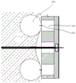
when the position of the non-casting opening 211 corresponds to the support pile 100, as shown in fig. 2, the top form 210 is fixedly connected to the support pile 100 through the right angle corner brace 400, two fixing edges of the right angle corner brace 400 are respectively connected and fixed to the support pile 100 and the top form 210 through the first fastener 410, the selection of the first fastener 410 is not limited herein, and may be a fastening bolt or a screw, and the specific fastening number of the first fastener 410 is also selected according to actual needs.
When the position of the pouring opening 211 corresponds to the support pile 100, as shown in fig. 3, since the connection position of the top mold 210 is the pouring opening 211 and has no connection plane, it is only necessary to connect and fix the inner mold 240 and the support pile 100 by the second fastening member 420, the selection of the second fastening member 420 is not limited, and a suitable fastening member is selected according to actual requirements.
The anchor rod 300 penetrates through the inner side die 240 and the outer side die 220 of the waist rail die 200 at a certain angle, the other side of the anchor rod 300 is inserted into the anchor rod hole 111, and the outer side of the anchor rod 300 is coated with a through-long soft sleeve to be isolated from the concrete 250, so that the subsequent cementation with the concrete 250 in the waist rail die 200 is avoided.
The anchor rod 300 is located at the position of the space area 500 between the piles, the steel sleeve 600 is further sleeved, the length of the steel sleeve 600 is guaranteed to meet the condition that at least one end of the steel sleeve 600 is inserted into the anchor rod hole 111 and is not less than 300mm, the other end of the steel sleeve is inserted into the waist beam mold 200 and is not less than 300mm, and the steel sleeve 600 is filled with water slurry.
An inter-pile empty area 500 is formed between every two adjacent support piles 100, soil layers 110 and inner side molds 240, the support assembly 800 is arranged below the wale mold 200 corresponding to the inter-pile empty area 500 and comprises a base 830, a telescopic support 820 arranged on the base 830, a support frame 810 positioned at the top of the telescopic support 820 and a support module arranged at the top of the support frame 810, and the support module extends into the soil layers 110 from the bottom of the wale mold 200; the top of the inter-pile vacant area 500 is supported to form a cavity opened at the upper side for filling the concrete 250 therein.
As shown in fig. 5 and 6, the supporting module comprises a plurality of supporting plates 840 which are mutually inserted, two sides of the steel membrane are respectively provided with a first inserting portion 841 and a second inserting portion 842, the first inserting portion 841 and the second inserting portion 842 are matched and inserted, a plurality of adjacent supporting plates 840 are connected into a whole, when the supporting plates 840 can be directly inserted and connected to the side wall of the soil layer 110, only one side corresponding to the waist beam mold 200 is required to be provided with the telescopic supporting frame 810, the other side is supported by the supporting plate 840 through the soil layer 110, when the side wall of the soil layer 110 is hard, and the supporting plate 840 cannot be inserted, one side of the soil layer 110 is required to be additionally provided with a group of telescopic supporting frames 810 for supporting the supporting plate 840 on one side of the soil layer 110.
In some embodiments of the present application, in order to facilitate positioning of the first inserting portion 841 and the second inserting portion 842, the top surface of the supporting frame 810 is further provided with a plurality of brackets having openings facing the supporting plate 840, the brackets correspond to the inserting positions of the first inserting portion 841 and the second inserting portion 842, and the protruding positions of the first inserting portion 841 and the second inserting portion 842 are located in the brackets, so as to ensure the flatness of the top surface of the supporting frame 810 and facilitate the installation of the supporting plate 840.
One side of the anchor rod 300 extending out of the outer side mold 220 is fixed by an anchor 320, a pressure bearing plate 310 is arranged between the anchor 320 and the outer side mold 220 and used for dispersing the pressure of the anchor 320, the pressure bearing plate 310 can be a steel backing plate or a backing plate formed by pultrusion of fiber composite materials, and the anchor 320 can be a conventional finished product.
In other embodiments of the present application, a support rib 430 is further disposed at the bottom of the wale mold 200 in the horizontal direction, the support rib 430 is installed in the horizontal direction, one end of the support rib 430 is inserted into the support pile 100, and the end of the support pile 100 extending out is located below the wale bottom mold 230 and contacts with the bottom mold 230 for supporting, so as to provide upward supporting force for the wale mold 200.
An included angle is formed between the bottom die 230 and the horizontal plane, the included angle is consistent with the included angle between the anchor rod 300 and the horizontal plane, the width of the outer die 220 is generally not less than 200mm and not more than 400mm, the horizontal width of the top is generally not less than 150mm, the widths of the spacing die and the hole are generally not less than 200mm and not more than 300mm, and raw materials are saved as far as possible while the structural strength is guaranteed.
The through hole of the outer mold 220 should be arranged at the middle part of the side edge, the connection line with the through hole of the inner mold 240 is the same with the inclination and inclination angle of the anchor rod 300, and the size of the through hole is adapted according to the size of the rod body bundle of the anchor rod 300, so that the size of the through hole is not too large.
The included angle between the outer die 220 and the anchor rod 300 is 90 degrees, so that one end of the anchor rod 300 extending out of the outer die 220 is perpendicular to the surface of the outer die 220, and the bearing plate 310 and the anchor 320 are convenient to install.
The anchor rod 300 is provided with the soft sleeve outside, avoids follow-up concrete 250 cemented with in the waist rail mould 200, and the anchor rod 300 that is located the empty area 500 between the stake still cup joints steel casing 600 outward, and steel casing 600 one end is pegged graft and is no less than 300mm in the anchor rod hole 111, and the other end is pegged graft and is no less than 300mm in the waist rail mould 200, and steel casing 600 pours grout with cup jointing between the soft sleeve in the anchor rod 300 outside.
In another aspect, the present invention also provides a construction method of a wale supporting structure, which includes the steps of:
1) after the supporting piles 100 are constructed, anchor rod holes 111 are processed on the side walls of soil layers 110 between adjacent supporting piles 100, and the aperture of each anchor rod hole 111 is larger than the outer diameter of each steel pipe sleeve; the through hole of the outer side mold 220 should be arranged in the middle of the side edge, the connection line with the through hole of the inner side mold 240 is the same with the inclination and inclination angle of the anchor rod 300, the size of the through hole is adapted according to the size of the anchor rod 300, the through hole is not too large, and the leakage of the subsequent poured concrete 250 is avoided;
2) inserting the anchor rod 300 sleeved with the soft sleeve on the outer side into the anchor rod hole 111, sleeving the steel sleeve 600 on the anchor rod 300 at the position of the inter-pile empty area 500 between the adjacent support piles 100, wherein the material is made of steel plates or is the same as the material of the waist beam mold 200, the steel sleeve 600 is connected and fixed with the waist beam molds on the two sides by using a plurality of fixing screws, one end of the steel sleeve 600 is inserted into the anchor rod hole 111 and is not less than 300mm in length, the other end of the steel sleeve is inserted into the waist beam mold 200 and is not less than 300mm in length, and cement slurry is filled in the steel sleeve 600;
3) according to the size requirement of an actual deep foundation pit or a side slope side wall, a plurality of waist beam moulds 200 are connected into a whole through a sleeve 900, an end cover 700 is installed on the waist beam mould 200 at the end part, the end cover 700 is fixed with the waist beam mould through a plurality of bolts, concrete 250 can be disassembled and reused after final setting, an anchor rod 300, a soft sleeve and a steel sleeve 600 penetrate through a through hole in an inner side mould 240, the anchor rod 300 body and the soft sleeve penetrate through an outer side mould 220, and after the anchor rod 300 penetrates through the waist beam mould 200, the end part of the anchor rod 300 extending out of the outer side mould 220 is fixed through a pressure bearing plate 310 and an anchorage device 320;
4) when the support pile 100 is in contact with the top mold 210 of the waist beam mold 200 at a position not provided with the pouring opening 211, the top mold 210 is fixedly connected with the support pile 100 by adopting the right-angle corner brace 400, and when the support pile 100 is in contact with a pouring hole, the inner wall of the inner side mold 240 at the pouring hole is fixedly connected with the support pile 100 through the second fastener 420;
horizontally fixing a supporting rib 430 at the bottom of the waist rail mould 200, wherein one end of the supporting rib 430 is fixed on the support pile 100;
fixing a support module below the position of the waist beam mold 200 corresponding to the inter-pile empty area 500;
in the case that the inner side mold 240 of the waist rail mold 200 is not located on the same vertical plane with the outer edge of the support pile 100, a support module is installed, and after the support module is installed, concrete 250 is poured to fill the gap between the waist rail mold 200 and the outer wall of the soil layer 110. The supporting plate 840 is made of a steel plate with the thickness of 4-5mm, the width of a single piece is 200-300mm, the length is generally 400-1000mm according to field configuration, the telescopic bracket 820 is adjusted according to field requirements, generally 300-1000mm, and the shape of the supporting plate 840 close to the side wall of the soil layer 110 is set to be an oblique edge;
when soil layer 110 lateral wall can be inserted to backup pad 840 one end, only establish the square timber skeleton and the telescopic bracket 810 that are on a parallel with waist rail mould 200 one side can, if soil layer 110 is too hard, when backup pad 840 can not insert into, need add a set of telescopic bracket 810 that is on a parallel with waist rail mould 200 direction in one side of soil layer 110 outer wall. The upper surface of the support plate 840 is coated with a release agent to facilitate subsequent removal.
5) Pouring concrete 250 into the waist rail mold 200 from the pouring port 211, watering and curing after final setting, pouring concrete 250 into the cavity between the piles, watering and curing after final setting, and smearing an isolating agent on the upper surface of the supporting plate 840 in advance;
6) removing the support assembly 800 below the waist rail mold 200;
7) the pre-stressed tension-locking of the anchor 300 is performed using a jack.
The waist rail mold 200 plays a role in casting concrete when a waist rail is cast, plays a role in replacing longitudinal steel bars and stirrups of a conventional waist rail when the anchor rod 300 is tensioned and subsequently operated, and is a disposable waist rail mold, and the material of the waist rail mold can be made of materials which are easy to install and have high quality, such as fiber composite materials.
Meanwhile, the simple formwork support of the empty area 500 between the piles is achieved, the supporting assembly 800 can be repeatedly used, cost is saved, compared with the prior art, the supporting assembly has the advantages of simplicity, rapidness, environmental protection and economy, and has great application value in projects such as deep foundation pit supporting and slope reinforcement.
The above examples are only intended to illustrate the technical solution of the present invention, but not to limit it; although the present invention has been described in detail with reference to the foregoing embodiments, it will be apparent to those skilled in the art that various changes may be made and equivalents may be substituted for elements thereof; and such modifications or substitutions do not depart from the spirit and scope of the corresponding technical solutions.