KR20130112697A - Metal air battery - Google Patents

Metal air battery Download PDF

Info

Publication number
KR20130112697A
KR20130112697A KR1020127031693A KR20127031693A KR20130112697A KR 20130112697 A KR20130112697 A KR 20130112697A KR 1020127031693 A KR1020127031693 A KR 1020127031693A KR 20127031693 A KR20127031693 A KR 20127031693A KR 20130112697 A KR20130112697 A KR 20130112697A
Authority
KR
South Korea
Prior art keywords
layer
positive electrode
metal
negative electrode
air battery
Prior art date
Application number
KR1020127031693A
Other languages
Korean (ko)
Inventor
마사노부 아이자와
Original Assignee
히다치 조센 가부시키가이샤
Priority date (The priority date is an assumption and is not a legal conclusion. Google has not performed a legal analysis and makes no representation as to the accuracy of the date listed.)
Filing date
Publication date
Priority claimed from JP2010128796A external-priority patent/JP2011253789A/en
Priority claimed from JP2010249938A external-priority patent/JP2012104273A/en
Priority claimed from JP2011071500A external-priority patent/JP5773699B2/en
Application filed by 히다치 조센 가부시키가이샤 filed Critical 히다치 조센 가부시키가이샤
Publication of KR20130112697A publication Critical patent/KR20130112697A/en

Links

Images

Classifications

    • HELECTRICITY
    • H01ELECTRIC ELEMENTS
    • H01MPROCESSES OR MEANS, e.g. BATTERIES, FOR THE DIRECT CONVERSION OF CHEMICAL ENERGY INTO ELECTRICAL ENERGY
    • H01M8/00Fuel cells; Manufacture thereof
    • H01M8/22Fuel cells in which the fuel is based on materials comprising carbon or oxygen or hydrogen and other elements; Fuel cells in which the fuel is based on materials comprising only elements other than carbon, oxygen or hydrogen
    • HELECTRICITY
    • H01ELECTRIC ELEMENTS
    • H01MPROCESSES OR MEANS, e.g. BATTERIES, FOR THE DIRECT CONVERSION OF CHEMICAL ENERGY INTO ELECTRICAL ENERGY
    • H01M4/00Electrodes
    • H01M4/86Inert electrodes with catalytic activity, e.g. for fuel cells
    • H01M4/8647Inert electrodes with catalytic activity, e.g. for fuel cells consisting of more than one material, e.g. consisting of composites
    • H01M4/8657Inert electrodes with catalytic activity, e.g. for fuel cells consisting of more than one material, e.g. consisting of composites layered
    • HELECTRICITY
    • H01ELECTRIC ELEMENTS
    • H01MPROCESSES OR MEANS, e.g. BATTERIES, FOR THE DIRECT CONVERSION OF CHEMICAL ENERGY INTO ELECTRICAL ENERGY
    • H01M12/00Hybrid cells; Manufacture thereof
    • H01M12/08Hybrid cells; Manufacture thereof composed of a half-cell of a fuel-cell type and a half-cell of the secondary-cell type
    • HELECTRICITY
    • H01ELECTRIC ELEMENTS
    • H01MPROCESSES OR MEANS, e.g. BATTERIES, FOR THE DIRECT CONVERSION OF CHEMICAL ENERGY INTO ELECTRICAL ENERGY
    • H01M12/00Hybrid cells; Manufacture thereof
    • H01M12/04Hybrid cells; Manufacture thereof composed of a half-cell of the fuel-cell type and of a half-cell of the primary-cell type
    • H01M12/06Hybrid cells; Manufacture thereof composed of a half-cell of the fuel-cell type and of a half-cell of the primary-cell type with one metallic and one gaseous electrode
    • HELECTRICITY
    • H01ELECTRIC ELEMENTS
    • H01MPROCESSES OR MEANS, e.g. BATTERIES, FOR THE DIRECT CONVERSION OF CHEMICAL ENERGY INTO ELECTRICAL ENERGY
    • H01M4/00Electrodes
    • H01M4/86Inert electrodes with catalytic activity, e.g. for fuel cells
    • HELECTRICITY
    • H01ELECTRIC ELEMENTS
    • H01MPROCESSES OR MEANS, e.g. BATTERIES, FOR THE DIRECT CONVERSION OF CHEMICAL ENERGY INTO ELECTRICAL ENERGY
    • H01M4/00Electrodes
    • H01M4/86Inert electrodes with catalytic activity, e.g. for fuel cells
    • H01M4/90Selection of catalytic material
    • H01M4/9016Oxides, hydroxides or oxygenated metallic salts
    • HELECTRICITY
    • H01ELECTRIC ELEMENTS
    • H01MPROCESSES OR MEANS, e.g. BATTERIES, FOR THE DIRECT CONVERSION OF CHEMICAL ENERGY INTO ELECTRICAL ENERGY
    • H01M4/00Electrodes
    • H01M4/86Inert electrodes with catalytic activity, e.g. for fuel cells
    • H01M2004/8678Inert electrodes with catalytic activity, e.g. for fuel cells characterised by the polarity
    • H01M2004/8689Positive electrodes
    • YGENERAL TAGGING OF NEW TECHNOLOGICAL DEVELOPMENTS; GENERAL TAGGING OF CROSS-SECTIONAL TECHNOLOGIES SPANNING OVER SEVERAL SECTIONS OF THE IPC; TECHNICAL SUBJECTS COVERED BY FORMER USPC CROSS-REFERENCE ART COLLECTIONS [XRACs] AND DIGESTS
    • Y02TECHNOLOGIES OR APPLICATIONS FOR MITIGATION OR ADAPTATION AGAINST CLIMATE CHANGE
    • Y02EREDUCTION OF GREENHOUSE GAS [GHG] EMISSIONS, RELATED TO ENERGY GENERATION, TRANSMISSION OR DISTRIBUTION
    • Y02E60/00Enabling technologies; Technologies with a potential or indirect contribution to GHG emissions mitigation
    • Y02E60/10Energy storage using batteries
    • YGENERAL TAGGING OF NEW TECHNOLOGICAL DEVELOPMENTS; GENERAL TAGGING OF CROSS-SECTIONAL TECHNOLOGIES SPANNING OVER SEVERAL SECTIONS OF THE IPC; TECHNICAL SUBJECTS COVERED BY FORMER USPC CROSS-REFERENCE ART COLLECTIONS [XRACs] AND DIGESTS
    • Y02TECHNOLOGIES OR APPLICATIONS FOR MITIGATION OR ADAPTATION AGAINST CLIMATE CHANGE
    • Y02EREDUCTION OF GREENHOUSE GAS [GHG] EMISSIONS, RELATED TO ENERGY GENERATION, TRANSMISSION OR DISTRIBUTION
    • Y02E60/00Enabling technologies; Technologies with a potential or indirect contribution to GHG emissions mitigation
    • Y02E60/30Hydrogen technology
    • Y02E60/50Fuel cells

Landscapes

  • Chemical & Material Sciences (AREA)
  • Chemical Kinetics & Catalysis (AREA)
  • Electrochemistry (AREA)
  • General Chemical & Material Sciences (AREA)
  • Engineering & Computer Science (AREA)
  • Manufacturing & Machinery (AREA)
  • Composite Materials (AREA)
  • Materials Engineering (AREA)
  • Life Sciences & Earth Sciences (AREA)
  • Sustainable Development (AREA)
  • Sustainable Energy (AREA)
  • Hybrid Cells (AREA)
  • Inert Electrodes (AREA)

Abstract

금속공기전지(11)는 정극(12), 부극(13), 전해질층(14) 및 공기 유입관(15)을 구비하는 이차전지다.
정극은 대략 유저 원통형의 다공질 부재이며, 알루미나로 형성된 정극 지지부(121), 도전성을 가진 페로브스카이트형 산화물로 형성된 정극 도전층(122), 및 이산화망간으로 형성된 정극 촉매층(123)을 구비한다.
부극은 스테인레스강으로 형성된 부극 지지부(131), 리튬 또는 리튬합금으로 형성된 부극 도전층(132)을 구비한다.
금속공기전지에서는 페로브스카이트형 산화물로 형성된 정극 도전층 상에 정극 촉매층을 형성함으로써, 탄소를 함유하지 않는 정극을 실현할 수 있다.
이에 따라 방전시 정극 상에 탄산리튬이 생성되는 것을 방지할 수 있고, 금속공기전지의 충전전압을 낮출 수 있다.
The metal air battery 11 is a secondary battery having a positive electrode 12, a negative electrode 13, an electrolyte layer 14, and an air inlet pipe 15.
The positive electrode is a porous member having a substantially user cylindrical shape, and includes a positive electrode support portion 121 made of alumina, a positive electrode conductive layer 122 made of conductive perovskite oxide, and a positive electrode catalyst layer 123 made of manganese dioxide.
The negative electrode includes a negative electrode support portion 131 formed of stainless steel and a negative electrode conductive layer 132 formed of lithium or lithium alloy.
In a metal-air battery, a positive electrode free of carbon can be realized by forming a positive electrode catalyst layer on a positive electrode conductive layer formed of a perovskite oxide.
Accordingly, it is possible to prevent the generation of lithium carbonate on the positive electrode during discharge, and to lower the charging voltage of the metal-air battery.

Description

금속공기전지{METAL AIR BATTERY}Metal Air Battery {METAL AIR BATTERY}

본 발명은 금속공기전지(金屬空氣電池)에 관한 것이다.
The present invention relates to a metal air battery.

종래로부터 금속을 부극(負極)의 활물질(活物質)로 하고, 공기 중의 산소를 정극(正極)의 활물질로 하는 금속공기전지가 알려져 있다. 예를 들면 일본국 공개특허 2008-66202호 공보(문헌1)에는 정극과 부극 사이에 전해질 함유층(電解質含有層)이 형성된 금속공기전지의 전해질에, 이온액체(ion 液體), 무기 미립자(無機微粒子) 및 전해질염(電解質鹽)을 함유시키는 것이 제안되어 있다. 또한 일본국 공개특허 2009-230981호 공보(문헌2)에는, 비수전해액(非水電解液) 속에 정극 및 부극이 배치된 금속공기전지에, 공기 중의 산소를 산소이온 전도성의 고체 전해질(固體電解質)을 통하여 정극에 공급하는 산소펌프를 설치하는 것이 제안되어 있다.Background Art Conventionally, metal air batteries are known in which metal is used as an active material of a negative electrode and oxygen in air is used as an active material of a positive electrode. For example, Japanese Laid-Open Patent Publication No. 2008-66202 (Patent 1) discloses an ionic liquid and an inorganic fine particle in an electrolyte of a metal-air battery in which an electrolyte-containing layer is formed between a positive electrode and a negative electrode. ) And an electrolyte salt have been proposed. In addition, Japanese Patent Laid-Open No. 2009-230981 (Patent 2) discloses a solid electrolyte having oxygen-conducting oxygen in air in a metal-air battery in which a positive electrode and a negative electrode are disposed in a nonaqueous electrolyte. It is proposed to install an oxygen pump for supplying the positive electrode through the air.

일본국 공개특허 2008-112724호 공보(문헌3)의 리튬공기 이차전지에서는, 정극이 산소의 흡방출기능(吸放出機能)을 구비하는 정극 촉매, 탄소재료 및 유기 바인더(탄소섬유 등)를 포함하고, 부극이 판상(板狀)의 리튬으로 형성된다. 정극 촉매로는 이산화망간(MnO2)이나 페로브스카이트형 산화물(perovskite type 酸化物) 등이 이용된다. 일본국 공개특허 2009-283381호 공보(문헌4)의 리튬공기 이차전지에서는, 정극이 탄소(C)를 주체로 하는 가스확산형 산소전극이며, 부극이 금속리튬 혹은 리튬이온의 흡장(吸藏) 및 방출 가능한 물질로 형성된다. 또한 정극은 20~60중량%의 페로브스카이트형 구조를 구비하는 철(Fe)계 산화물을 포함한다. In the lithium air secondary battery of JP-A-2008-112724 (Patent 3), the cathode includes a cathode catalyst, a carbon material, and an organic binder (carbon fiber, etc.) having an oxygen adsorption / discharge function. The negative electrode is formed of lithium in plate form. As the cathode catalyst, manganese dioxide (MnO 2 ), a perovskite type oxide, or the like is used. In the lithium air secondary battery of JP-A-2009-283381 (Patent 4), the positive electrode is a gas diffusion type oxygen electrode mainly composed of carbon (C), and the negative electrode is a metal lithium or lithium ion occlusion. And releasable materials. In addition, the positive electrode includes an iron (Fe) oxide having a perovskite structure of 20 to 60% by weight.

한편 금속공기전지에서는 충전(充電)시 부극 상에 금속이 국소적으로 석출(析出)됨에 의해 정극과 부극이 단락(短絡)할 우려가 있다. 따라서 정극과 부극 사이에 세퍼레이터(separator)를 설치함으로써 정극과 부극의 단락을 방지하는 방법이 제안되어 있다(예를 들면 문헌1 및 2 참조).On the other hand, in a metal air battery, there is a possibility that the positive electrode and the negative electrode are short-circuited because the metal is locally deposited on the negative electrode during charging. Therefore, the method of preventing the short circuit of a positive electrode and a negative electrode by providing a separator between a positive electrode and a negative electrode is proposed (for example, refer documents 1 and 2).

그런데 문헌1 내지 문헌4의 금속공기전지에서는 정극이 도전성(導電性) 물질로 탄소를 포함하기 때문에, 방전(放電)시 부극 금속의 탄산염인 탄산리튬(Li2CO3) 등이 정극 상에 석출된다. 이러한 금속공기전지에서는 충전시 탄산리튬을 전기분해하여 이온화하기 위하여 큰 에너지가 필요하기 때문에 충전전압이 높아져 버린다.However, in the metal air batteries of Documents 1 to 4, since the positive electrode contains carbon as a conductive material, lithium carbonate (Li 2 CO 3 ) or the like, which is a carbonate of the negative electrode metal, precipitates on the positive electrode during discharge. do. In such a metal-air battery, the charging voltage increases because a large amount of energy is required to electrolyze and ionize lithium carbonate during charging.

또한 금속공기전지에서는 정극이 다공질 부재(多孔質部材)로 형성되기 때문에 전해액이 정극을 침투하여 누출될 우려가 있다. 전해액이 누출될 경우 전지성능(전지용량 등)이 현저히 저하해 버린다.Moreover, in a metal air battery, since a positive electrode is formed from a porous member, there exists a possibility that electrolyte solution may leak through a positive electrode. If the electrolyte leaks, the battery performance (battery capacity, etc.) significantly decreases.

한편 금속공기전지에서 충전용 보조전극(즉 제3전극)을 설치하여, 방전시에 정극과 부극을 이용하고 충전시에 부극과 보조전극을 이용함으로써, 금속공기전지의 충전 및 방전의 성능을 향상시키는 방법이 고려된다. 그러나 이러한 금속공기전지에서도 충전시 부극 상에 금속이 국소적으로 석출되면 부극과 보조전극이 단락할 우려가 있다.
On the other hand, by installing a charging auxiliary electrode (that is, a third electrode) in a metal air battery, the positive electrode and the negative electrode are used for discharging, and the negative electrode and the auxiliary electrode are used for discharging, thereby improving the performance of charging and discharging the metal air battery. The method of making it is considered. However, even in such a metal air battery, if the metal is locally deposited on the negative electrode during charging, the negative electrode and the auxiliary electrode may be shorted.

본 발명은 금속공기전지에 관한 것으로서, 방전시 정극 상에 금속탄산염이 생성되는 것을 방지하는 것을 주목적으로 하고 있다. 또한 전해액이 정극을 침투하여 누출되는 것을 방지하는 것, 및 부극과 보조전극이 단락하는 것을 방지하는 것도 목적으로 하고 있다.
BACKGROUND OF THE INVENTION 1. Field of the Invention The present invention relates to a metal air battery, and aims to prevent the formation of metal carbonate on the positive electrode during discharge. It is also an object to prevent the electrolyte from leaking through the positive electrode and to prevent the short circuit between the negative electrode and the auxiliary electrode.

본 발명에 관한 하나의 바람직한 금속공기전지는, One preferred metal air battery according to the present invention,

금속을 포함하면서 방전시에 금속이온을 생성하는 부극과, A negative electrode containing metal and generating metal ions during discharge;

도전성을 가진 페로브스카이트형 산화물 및 산소환원반응(酸素還元反應)을 촉진하는 촉매를 포함하면서 탄소를 포함하지 않고, 방전시에 산소이온을 생성하는 다공질의 정극과, A porous positive electrode containing conductive perovskite oxide and a catalyst for promoting an oxygen reduction reaction and containing no carbon and generating oxygen ions at the time of discharge;

상기 부극과 상기 정극 사이에 배치되는 전해질층을Electrolyte layer disposed between the negative electrode and the positive electrode

구비한다. 이에 따라 방전시 정극 상에 금속탄산염이 생성되는 것을 방지할 수 있다.Respectively. Accordingly, it is possible to prevent the generation of metal carbonate on the positive electrode during discharge.

또한 상기 정극이, In addition, the positive electrode,

지지부(支持部)와, Support,

상기 지지부 상에 상기 페로브스카이트형 산화물로 형성된 도전막(導電膜)과,A conductive film formed of the perovskite oxide on the support portion;

상기 도전막 상에 상기 촉매로 형성된 촉매층(觸媒層)을A catalyst layer formed of the catalyst on the conductive film

구비하는 것이 바람직하다.It is preferable to provide.

보다 바람직한 금속공기전지는 상기 정극에 설치되고, 상기 전해질층에 포함된 전해액에 대하여 발액성(撥液性)을 가진 발액층(撥液層)을 추가로 구비한다. 이에 따라 전해액이 정극을 침투하여 누출되는 것을 방지할 수 있다.A more preferable metal-air battery is provided in the said positive electrode, and is further provided with the liquid repellent layer which has liquid repellency with respect to the electrolyte solution contained in the said electrolyte layer. As a result, the electrolyte solution can be prevented from leaking through the positive electrode.

본 발명에 관한 다른 바람직한 금속공기전지는, Another preferred metal air battery according to the present invention,

금속을 포함하면서 방전시에 금속이온을 생성하는 부극층과, A negative electrode layer containing metal and generating metal ions during discharge;

도전성 재료 및 산소환원반응을 촉진하는 촉매를 포함하고 방전시에 산소이온을 생성하는 다공질의 정극층과, A porous positive electrode layer containing a conductive material and a catalyst for promoting an oxygen reduction reaction and generating oxygen ions at discharge;

상기 부극층과 상기 정극층 사이에 배치되는 제1전해질층과, A first electrolyte layer disposed between the negative electrode layer and the positive electrode layer,

상기 부극층에 있어서 상기 정극층과 반대측 면에 대향하는 면을 구비하는 보조 전극층과, An auxiliary electrode layer having a surface opposed to the surface opposite to the positive electrode layer in the negative electrode layer;

상기 부극층과 상기 보조 전극층 사이에 배치되고 상기 제1전해질층과 연통하는 제2전해질층을A second electrolyte layer disposed between the negative electrode layer and the auxiliary electrode layer and in communication with the first electrolyte layer;

구비하고, Respectively,

상기 부극층의 상기 면이 상기 보조 전극층의 상기 면의 엣지부와 대향하는 부위보다 외측으로 확장된 부위를 구비하고, The surface of the negative electrode layer has a portion that extends outward from a portion facing the edge portion of the surface of the auxiliary electrode layer,

충전시에 상기 부극층과 상기 보조 전극층 사이에 전압이 부여됨으로써 상기 부극층 상에 상기 금속이 석출된다.During charging, the metal is deposited on the negative electrode layer by applying a voltage between the negative electrode layer and the auxiliary electrode layer.

이에 따라 부극층과 보조 전극층이 단락하는 것을 방지할 수 있다.As a result, the short circuit between the negative electrode layer and the auxiliary electrode layer can be prevented.

더 바람직하게는 상기 정극층, 상기 부극층 및 상기 보조 전극층이 통상(筒狀)이며, 상기 정극층이 상기 부극층의 내측에 배치되고, 상기 보조 전극층이 상기 부극층의 외측에 배치된다.More preferably, the positive electrode layer, the negative electrode layer, and the auxiliary electrode layer are ordinary, the positive electrode layer is disposed inside the negative electrode layer, and the auxiliary electrode layer is disposed outside the negative electrode layer.

상기 도전성 재료가 페로브스카이트형 산화물이며, 상기 정극층이 탄소를 포함하지 않는 경우에는 방전시 정극층 상에 금속탄산염이 생성되는 것을 방지할 수 있다.When the conductive material is a perovskite oxide and the positive electrode layer does not contain carbon, it is possible to prevent the formation of metal carbonate on the positive electrode layer during discharge.

상기의 목적 및 다른 목적, 특징, 태양 및 이점은 첨부한 도면을 참조하여 이하에 행하는 본 발명의 상세한 설명으로 밝힌다.
The above and other objects, features, aspects, and advantages will be apparent from the following detailed description of the invention made with reference to the accompanying drawings.

도1은 제1실시형태에 관한 금속공기전지의 종단면도이다.
도2는 금속공기전지의 횡단면도이다.
도3은 제2실시형태에 관한 금속공기전지의 종단면도이다.
도4는 금속공기전지의 횡단면도이다.
도5는 제3실시형태에 관한 금속공기전지의 횡단면도이다.
도6은 제4실시형태에 관한 금속공기전지의 횡단면도이다.
도7은 제5실시형태에 관한 금속공기전지의 종단면도이다.
도8은 제6실시형태에 관한 금속공기전지의 종단면도이다.
도9는 금속공기전지의 횡단면도이다.
도10은 금속공기전지의 다른 예의 횡단면도이다.
도11은 제7실시형태에 관한 금속공기전지의 종단면도이다.
도12는 금속공기전지의 횡단면도이다.
도13은 제8실시형태에 관한 금속공기전지의 횡단면도이다.
도14는 제9실시형태에 관한 금속공기전지의 횡단면도이다.
도15는 제10실시형태에 관한 금속공기전지의 종단면도이다.
도16은 제11실시형태에 관한 금속공기전지를 나타낸 종단면도이다.
도17은 금속공기전지를 나타낸 횡단면도이다.
도18.A는 비교예인 금속공기전지에서의 부극층 및 보조 전극층을 나타낸 도면이다.
도18.B는 다른 비교예인 금속공기전지에서의 부극층 및 보조 전극층을 나타낸 도면이다.
도19는 부극층 및 보조 전극층을 나타낸 도이다.
1 is a longitudinal sectional view of a metal-air battery according to a first embodiment.
2 is a cross-sectional view of a metal air battery.
3 is a longitudinal cross-sectional view of the metal-air battery according to the second embodiment.
4 is a cross-sectional view of a metal air battery.
5 is a cross sectional view of a metal-air battery according to a third embodiment.
6 is a cross sectional view of a metal-air battery according to a fourth embodiment.
7 is a longitudinal cross-sectional view of the metal-air battery according to the fifth embodiment.
8 is a longitudinal cross-sectional view of the metal-air battery according to the sixth embodiment.
9 is a cross-sectional view of a metal air battery.
10 is a cross sectional view of another example of a metal-air battery.
11 is a longitudinal cross-sectional view of the metal-air battery according to the seventh embodiment.
12 is a cross-sectional view of a metal air battery.
13 is a cross sectional view of a metal-air battery according to an eighth embodiment.
14 is a cross sectional view of a metal-air battery according to a ninth embodiment.
15 is a longitudinal sectional view of the metal-air battery according to the tenth embodiment.
16 is a longitudinal sectional view showing a metal air battery according to an eleventh embodiment.
17 is a cross-sectional view showing a metal air battery.
18A shows a negative electrode layer and an auxiliary electrode layer in a metal-air battery as a comparative example.
18.B is a view showing a negative electrode layer and an auxiliary electrode layer in another metal air battery of Comparative Example.
19 illustrates a negative electrode layer and an auxiliary electrode layer.

도1은 본 발명의 제1실시형태에 관한 금속공기전지(11)을 나타낸 종단면도이다. 금속공기전지(11)는 원통형(圓筒型, 여기에서 원통형이라 함은, 물리적으로 정확한 원통형은 물론 대략적인 원통형인 것도 포함하는 의미이다. 이하 같다.)이며, 도1은 금속공기전지(11)의 중심축(J1)을 포함하는 단면을 나타낸다. 도2는 금속공기전지(11)를 도1의 II-II 위치에서 절단한 횡단면도이다. 도1 및 도2에 나타나 있는 바와 같이 금속공기전지(11)는 정극(12), 부극(13), 전해질층(14) 및 공기 유입관(15)을 구비하는 이차전지로서, 중심축(J1)으로부터 지름방향의 외측을 향하여 공기 유입관(15), 정극(12), 전해질층(14) 및 부극(13)이 순차적으로 동심원(同心圓) 모양으로 배치된다. 바꾸어 말하면 금속공기전지(11)는 외주(外周)에 부극(13)이 배치되고 내주(內周)에 정극(12)이 배치되는 원통형이다. 1 is a longitudinal sectional view showing a metal air battery 11 according to a first embodiment of the present invention. The metal air battery 11 is a cylindrical shape (i.e., the term "cylindrical" herein means a physically accurate cylindrical shape as well as an approximate cylindrical shape. The following description will be given). The cross section containing the central axis J1 of () is shown. FIG. 2 is a cross-sectional view of the metal air battery 11 cut at the II-II position of FIG. 1. As shown in FIGS. 1 and 2, the metal-air battery 11 is a secondary battery including a positive electrode 12, a negative electrode 13, an electrolyte layer 14, and an air inlet pipe 15, and has a central axis J1. ), The air inflow pipe 15, the positive electrode 12, the electrolyte layer 14, and the negative electrode 13 are sequentially arranged in a concentric shape from the outside in the radial direction. In other words, the metal-air battery 11 is cylindrical in which the negative electrode 13 is arrange | positioned at the outer periphery and the positive electrode 12 is arrange | positioned at the inner periphery.

정극(12)은 유저 원통형(有底圓筒形)의 다공질 부재이며, 각각이 유저 원통형인 정극 지지부(121), 정극 도전층(122) 및 정극 촉매층(123)을 구비한다. 정극 도전층(122)은 정극 지지부(121)의 외측면 및 외저면 상에 적층되고, 정극 촉매층(123)은 정극 도전층(122)의 외측면 및 외저면 상에 적층된다. 정극(12)에는 정극 도전층(122)의 외측면의 일부에 정극 촉매층(123)을 대신하여 정극 집전체(124)가 설치되고, 도1에 나타나 있는 바와 같이 정극 집전체(124)의 상단에 정극 집전단자(125)가 접속된다. 정극(12) 및 정극 집전체(124)에 탄소(C)는 포함되지 않는다.The positive electrode 12 is a user cylindrical porous member, and includes a positive electrode support 121, a positive electrode conductive layer 122, and a positive electrode catalyst layer 123 each of which is a user cylindrical. The positive electrode conductive layer 122 is laminated on the outer side and the outer bottom of the positive electrode support part 121, and the positive electrode catalyst layer 123 is laminated on the outer side and the outer bottom of the positive electrode conductive layer 122. In the positive electrode 12, a positive electrode current collector 124 is provided on a part of the outer surface of the positive electrode conductive layer 122 in place of the positive electrode catalyst layer 123, and as shown in FIG. 1, an upper end of the positive electrode current collector 124. The positive electrode current collector terminal 125 is connected to it. Carbon (C) is not included in the positive electrode 12 and the positive electrode current collector 124.

정극 지지부(121)는 알루미나(산화알루미늄: Al2O3)나 지르코니아(zirconia), 세라믹, 스테인레스강 등의 금속에 의하여 형성된 다공질 부재이며, 본 실시형태에서 정극 지지부(121)는 절연체인 알루미나로 형성된다. 정극 지지부(121)의 형성은 압출성형, CIP(Cold Isostatic Press: 냉간등방압프레스) 및 소성, 또는 HIP(Hot Isostatic Press: 열간등방압프레스) 등으로 이루어진다.The positive electrode support portion 121 is a porous member formed of metal such as alumina (aluminum oxide: Al 2 O 3 ), zirconia, ceramic, stainless steel, etc. In the present embodiment, the positive electrode support portion 121 is made of alumina, which is an insulator. Is formed. The positive electrode support portion 121 is formed by extrusion molding, cold isostatic press (CIP) and firing, or hot isostatic press (HIP).

정극 도전층(122)은 도전성을 가진 페로브스카이트형 산화물(보통은 분체형(粉體型))에 의하여 주로 형성된 다공질의 얇은 도전막(導電膜)이며, 바람직하게는 화학식A1-xBO3(0.9≤1-x<1.0)으로 나타나는 페로브스카이트형 산화물로 형성된다. 본 실시형태에서 정극 도전층(122)은 란탄계의 페로브스카이트형 산화물(구체적으로는 란탄 스트론튬 망가나이트(LSM:La(Sr)MnO3)나 란탄 스트론튬 코발타이트(LSC:La(Sr)CoO3) 등의 A사이트에 란탄을 포함하는 페로브스카이트형 산화물)로 형성된다. 정극 도전층(122)의 형성은 슬러리 코트법, 수열합성법, CVD(Chemical Vapor Deposition: 화학증착) 또는 PVD(Physical Vapor Deposition: 물리증착) 등으로 이루어진다.The positive electrode conductive layer 122 is a porous thin conductive film mainly formed of a conductive perovskite oxide (usually a powder), and is preferably of Formula A 1-x BO. It is formed of a perovskite oxide represented by 3 (0.9 ≦ 1-x <1.0). In the present embodiment, the cathode conductive layer 122 is made of lanthanum-based perovskite oxide (specifically, lanthanum strontium manganite (LSM: La (Sr) MnO 3 ) or lanthanum strontium cobaltite (LSC: La (Sr) CoO). 3 ) a perovskite-type oxide containing lanthanum at the A site such as 3 ). The positive electrode conductive layer 122 is formed by a slurry coating method, a hydrothermal synthesis method, chemical vapor deposition (CVD), physical vapor deposition (PVD), or the like.

정극 촉매층(123)은 산소환원반응을 촉진하는 촉매인 망간(Mn)이나 니켈(Ni), 코발트(Co) 등의 금속 산화물로 주로 형성된 다공질 부재이다. 정극 촉매층(123)은 백금(Pt)이나 팔라듐(Pd), 은(Ag), 로듐(Rh), 루테늄(Ru)과 같은 귀금속, 또는 이들의 귀금속과 상기 금속 산화물의 혼합물로 형성되어도 좋다. 본 실시형태에서 정극 촉매층(123)은 β형(루틸형)의 결정구조를 구비하는 이산화망간(MnO2)으로 형성된다. 정극 촉매층(123)의 형성은 슬러리 코트법 및 소성, 수열합성법, CVD 또는 PVD 등으로 이루어진다.The positive electrode catalyst layer 123 is a porous member mainly formed of metal oxides such as manganese (Mn), nickel (Ni), and cobalt (Co), which are catalysts for promoting an oxygen reduction reaction. The positive electrode catalyst layer 123 may be formed of a precious metal such as platinum (Pt), palladium (Pd), silver (Ag), rhodium (Rh), ruthenium (Ru), or a mixture of these precious metals and the metal oxide. In this embodiment, the positive electrode catalyst layer 123 is formed of manganese dioxide (MnO 2 ) having a beta (rutile) crystal structure. The positive electrode catalyst layer 123 is formed by a slurry coating method and baking, hydrothermal synthesis method, CVD or PVD.

도1 및 도2에 나타나 있는 바와 같이, 부극(13)은 유저 원통형인 부극 지지부(131), 및 부극 지지부(131)의 내측면과 내저면 상에 적층된 유저 원통형의 부극 도전층(132)을 구비한다. 부극 지지부(131)는 금속 등의 도전성 재료(본 실시형태에서는 스테인레스강)로 형성된 부극 집전체이고, 부극 지지부(131)의 외측면에는 도1에 나타나 있는 바와 같이 부극 집전단자(133)가 설치된다. 부극 도전층(132)은 리튬(Li)이나 아연(Zn) 등의 금속, 또는 당해 금속을 포함하는 합금으로 형성된 얇은 도전막이며, 본 실시형태에서 부극 도전층(132)은 리튬 또는 리튬합금으로 형성된다. 부극 도전층(132)의 형성은 예를 들면 슬러리 코트법으로 이루어진다.As shown in FIGS. 1 and 2, the negative electrode 13 is a negative electrode support 131 that is a user cylindrical shape, and a user cylindrical negative electrode conductive layer 132 laminated on the inner and inner bottom surfaces of the negative electrode support 131. It is provided. The negative electrode support portion 131 is a negative electrode current collector formed of a conductive material such as metal (stainless steel in this embodiment), and a negative electrode current collector terminal 133 is provided on the outer surface of the negative electrode support portion 131 as shown in FIG. 1. do. The negative electrode conductive layer 132 is a thin conductive film formed of a metal such as lithium (Li) or zinc (Zn), or an alloy containing the metal. In this embodiment, the negative electrode conductive layer 132 is formed of lithium or lithium alloy. Is formed. The negative electrode conductive layer 132 is formed by, for example, a slurry coating method.

전해질층(14)은 비수계 전해질(非水系電解質)로 형성되고, 본 실시형태에서는 유기용제계(有機溶劑系)의 전해질 용액이 정극(12)과 부극(13) 사이에 충전(배치)된 것으로 형성된다. 전해질층(14)은 정극(12)의 정극 촉매층(123), 정극 집전체(124), 및 부극(13)의 부극 도전층(132)에 접한다. 전해질층(14)의 상면은 정극 지지부(121)의 외측면 및 부극 지지부(131)의 내측면에 접하는 원환형(圓環型, 여기에서 원환형이라 함은, 물리적으로 정확한 원환형은 물론 대략적으로 원환형인 것도 포함하는 의미이다. 이하 같다.)의 중간마개(151)로 폐쇄되고, 중간마개(151)의 상방에는 중간마개(151)와 동일한 형상의 바깥마개(152)가 설치되어서 유저 원통형인 부극(13)의 상부개구가 폐쇄된다.The electrolyte layer 14 is formed of a non-aqueous electrolyte, and in this embodiment, an electrolyte solution of an organic solvent system is filled (disposed) between the positive electrode 12 and the negative electrode 13. It is formed to be. The electrolyte layer 14 is in contact with the positive electrode catalyst layer 123 of the positive electrode 12, the positive electrode current collector 124, and the negative electrode conductive layer 132 of the negative electrode 13. The upper surface of the electrolyte layer 14 is in an annular shape which is in contact with the outer surface of the positive electrode support portion 121 and the inner surface of the negative electrode support portion 131. It is also meant to include an annular shape, which is the same as below.) The outer stopper 151 is closed to the middle stopper 151, and the upper stopper 152 having the same shape as the middle stopper 151 is installed above the user. The upper opening of the cylindrical negative electrode 13 is closed.

공기 유입관(15)은 유저 원통형 정극(12)의 내측에 배치되고, 공기 유입관(15)의 하단은 정극(12)의 정극 지지부(121)의 바닥부 근방에 위치한다. 공기 유입관(15)의 상단은 공기로부터 수분 및 이산화탄소를 제거하는 제거부(153)에 접속된다. 제거부(153)에서는 막분리법 또는 흡착에 의하여 공기 중의 수분 및 이산화탄소의 제거가 이루어진다. 공기(즉 수분 및 이산화탄소가 제거된 공기)는 제거부(153)로부터 공기 유입관(15)을 통하여 정극(12)의 내측 바닥부 근방으로 인도되어, 정극(12)에 공급되면서 정극(12)의 내측면에 따라 상승하여 정극(12)의 상부 개구를 통하여 외부로 배출된다. 금속공기전지(11)에서는 공기 유입관(15)이 제거부(153)로부터의 공기를 정극(12)에 공급하는 가스 공급부가 된다. 정극(12)에 공급된 공기는 다공질 부재인 정극 지지부(121) 및 정극 도전층(122)을 통과하여 정극 촉매층(123)에 공급된다.The air inlet pipe 15 is disposed inside the user cylindrical positive electrode 12, and the lower end of the air inlet pipe 15 is located near the bottom of the positive electrode support part 121 of the positive electrode 12. The upper end of the air inlet pipe 15 is connected to a removal unit 153 for removing water and carbon dioxide from the air. In the removing unit 153, water and carbon dioxide are removed from the air by membrane separation or adsorption. Air (ie, air from which moisture and carbon dioxide have been removed) is guided from the remover 153 through the air inlet pipe 15 to the inner bottom of the positive electrode 12, and is supplied to the positive electrode 12 while being supplied to the positive electrode 12. It rises along the inner side of and discharges to the outside through the upper opening of the positive electrode 12. In the metal-air battery 11, the air inlet pipe 15 is a gas supply unit for supplying air from the removal unit 153 to the positive electrode 12. Air supplied to the positive electrode 12 is supplied to the positive electrode catalyst layer 123 through the positive electrode support part 121 and the positive electrode conductive layer 122 which are porous members.

금속공기전지(11)에서 방전이 이루어질 때에는, 부극 집전단자(133)와 정극 집전단자(125)가 부하(예를 들면 조명기구 등)를 통하여 전기적으로 접속된다. 부극(13)에서는 부극 도전층(132)에 포함된 리튬이 산화되어 리튬이온(Li+)이 생성되고, 전자는 부극 집전단자(133), 정극 집전체(124) 및 정극 집전단자(125)를 통하여 정극(12)에 공급된다. 정극(12)에서는 공기 유입관(15)으로부터 공급된 공기 중의 산소가 부극(13)으로부터 공급된 전자에 의하여 환원되어서 산소이온(O2-)이 생성된다. 정극(12)에서는 정극 촉매층(123)에 포함된 정극 촉매에 의하여 산소이온의 생성(즉 산소의 환원반응)이 촉진되기 때문에, 당해 환원반응에 소비되는 에너지에 의한 과전압이 작아지고, 금속공기전지(11)의 방전 전압을 높일 수 있다. 정극(12)에서 생성된 산소이온은 부극(13)으로부터 전해질층(14) 속으로 용해된 리튬이온과 결합하고, 이에 따라 산화리튬(Li2O)이 생성된다.When discharge is performed in the metal-air battery 11, the negative electrode current collector terminal 133 and the positive electrode current collector terminal 125 are electrically connected through a load (for example, a lighting device). In the negative electrode 13, lithium included in the negative electrode conductive layer 132 is oxidized to generate lithium ions (Li +), and electrons are used to connect the negative electrode current collector terminal 133, the positive electrode current collector 124, and the positive electrode current collector terminal 125. It is supplied to the positive electrode 12 through. In the positive electrode 12, oxygen in the air supplied from the air inlet pipe 15 is reduced by the electrons supplied from the negative electrode 13 to generate oxygen ions O 2 −. In the positive electrode 12, since the generation of oxygen ions (that is, the reduction reaction of oxygen) is promoted by the positive electrode catalyst included in the positive electrode catalyst layer 123, the overvoltage caused by the energy consumed in the reduction reaction is reduced, and the metal air battery The discharge voltage of (11) can be raised. Oxygen ions generated in the positive electrode 12 are combined with lithium ions dissolved from the negative electrode 13 into the electrolyte layer 14, thereby producing lithium oxide (Li 2 O).

한편 금속공기전지(11)에서 충전이 이루어질 때에는 부극 집전단자(133)와 정극 집전단자(125) 사이에 전압이 부여되고, 정극(12)에서 산화리튬이 분해되면서 산소이온으로부터 정극 집전체(124)를 통하여 정극 집전단자(125)로 전자가 공급되어 산소가 발생한다. 부극(13)에서는 부극 집전단자(133)로 공급되는 전자에 의하여 리튬이온이 환원되어서 부극 도전층(132)의 표면에 리튬이 석출된다. 정극(12)에서는 정극 촉매층(123)에 포함된 정극 촉매에 의하여 산소의 발생이 촉진되기 때문에, 과전압이 작아지고 금속공기전지(11)의 충전전압을 낮출 수 있다.On the other hand, when charging is performed in the metal-air battery 11, a voltage is applied between the negative electrode current collector terminal 133 and the positive electrode current collector terminal 125, and lithium oxide is decomposed in the positive electrode 12, so that the positive electrode current collector 124 is separated from oxygen ions. Electron is supplied to the positive electrode current collector terminal 125 through the generation of oxygen. In the negative electrode 13, lithium ions are reduced by electrons supplied to the negative electrode current collector terminal 133, and lithium is deposited on the surface of the negative electrode conductive layer 132. In the positive electrode 12, since generation of oxygen is promoted by the positive electrode catalyst included in the positive electrode catalyst layer 123, the overvoltage is reduced and the charging voltage of the metal-air battery 11 can be lowered.

그런데 일반적인 금속공기전지의 정극은 도전성을 얻기 위하여 탄소를 주체로 하고, 당해 탄소에 산소의 환원반응을 촉진하는 정극 촉매가 첨가되어 있다. 그러나 이러한 금속공기전지에서는 방전시에 생성되는 리튬이온이 탄산리튬(Li2CO3)으로 정극 상에 석출되고, 충전시 탄산리튬을 전기분해하여 이온화하기 위하여 큰 에너지가 필요하기 때문에 충전전압이 높아져 버린다.By the way, the positive electrode of the general metal-air battery mainly uses carbon as a main material for obtaining conductivity, and a positive electrode catalyst for promoting the reduction reaction of oxygen is added to the carbon. However, in such a metal-air battery, lithium ions generated at the time of discharge are deposited on the positive electrode with lithium carbonate (Li 2 CO 3 ), and the charging voltage becomes high because large energy is required to electrolyze and ionize the lithium carbonate during charging. Throw it away.

이에 대하여 본 실시형태에 관한 금속공기전지(11)에서는, 페로브스카이트형 산화물로 형성된 정극 도전층(122) 상에 정극 촉매층(123)을 형성함으로써, 탄소를 함유하지 않는 정극(12)을 실현할 수 있다. 이에 따라 방전시 정극(12) 상에 탄산리튬이 생성되는 것을 방지할 수 있고, 금속공기전지(11)의 충전전압을 낮출 수 있다. 또한 정극 도전층(122)이 도전성 높은 란탄계 페로브스카이트형 산화물을 포함하고 있기 때문에, 금속공기전지(11)의 방전전압을 높일 수 있다. 또한 정극 도전층(122)에 포함된 페로브스카이트형 산화물이 화학식A1-xBO3(0.9≤1-x<1.0)으로 나타나는 것이기 때문에, 정극 도전층(122)이 수분에 의하여 열화해 버리는 것을 방지하고, 금속공기전지(11)의 내구성을 향상시킬 수 있다.In contrast, in the metal-air battery 11 according to the present embodiment, the positive electrode catalyst layer 123 is formed on the positive electrode conductive layer 122 formed of the perovskite oxide to realize the positive electrode 12 containing no carbon. Can be. Accordingly, it is possible to prevent the generation of lithium carbonate on the positive electrode 12 during discharge, and to lower the charging voltage of the metal-air battery 11. In addition, since the positive electrode conductive layer 122 contains a highly conductive lanthanum-based perovskite oxide, the discharge voltage of the metal-air battery 11 can be increased. In addition, since the perovskite oxide contained in the positive electrode conductive layer 122 is represented by the general formula A 1-x BO 3 (0.9 ≦ 1-x <1.0), the positive electrode conductive layer 122 is deteriorated by moisture. And the durability of the metal-air battery 11 can be improved.

금속공기전지(11)에서는 정극(12)의 정극 도전층(122)이 정극 지지부(121)에 의하여 지지(담지)되는 얇은 도전막이기 때문에, 비교적 고가(高價)인 페로브스카이트형 산화물의 사용량을 줄일 수 있다. 그 결과 금속공기전지(11)의 제조비용을 절감할 수 있다. 또한 부극(13)이 높은 이론전압 및 전기 화학당량을 가진 리튬 또는 리튬합금을 포함하고 있기 때문에 금속공기전지(11)의 용량을 높일 수 있다.In the metal-air battery 11, since the positive electrode conductive layer 122 of the positive electrode 12 is a thin conductive film supported (supported) by the positive electrode support part 121, the amount of perovskite oxide that is relatively expensive is used. Can be reduced. As a result, the manufacturing cost of the metal-air battery 11 can be reduced. In addition, since the negative electrode 13 contains lithium or a lithium alloy having a high theoretical voltage and an electrochemical equivalent, the capacity of the metal-air battery 11 can be increased.

상기한 바와 같이 금속공기전지(11)는 부극(13) 및 정극(12)이 각각 외주 및 내주에 배치되는 원통형이기 때문에, 금속공기전지(11)의 대형화가 요구될 경우에도 부극 도전층(132)이나 정극 도전층(122)과 같은 박막형(薄膜型)의 층을 용이하게 형성할 수 있다. 즉 금속공기전지(11)의 대형화에 용이하게 대응할 수 있다. 또한 공기 유입관(15)을 통해 수분 및 이산화탄소가 제거된 공기가 정극(12)으로 공급됨으로써, 공기 중의 이산화탄소와 리튬이온이 반응하여 정극(12)에 탄산리튬이 부착되는 것이 방지됨과 함께, 부극(13)의 부극 도전층(132)에 포함된 리튬이 수분과 반응하여 부극 도전층(132)이 열화해 버리는 것도 방지된다.As described above, the metal air battery 11 has a cylindrical shape in which the negative electrode 13 and the positive electrode 12 are disposed on the outer circumference and the inner circumference, respectively, and thus, even when the metal air battery 11 needs to be enlarged, the negative electrode conductive layer 132 ) And a thin film type layer such as the positive electrode conductive layer 122 can be easily formed. In other words, it is possible to easily cope with the increase in size of the metal-air battery 11. In addition, the air from which moisture and carbon dioxide have been removed is supplied to the positive electrode 12 through the air inlet pipe 15, thereby preventing lithium carbonate from adhering to the positive electrode 12 by reacting carbon dioxide and lithium ions in the air. The lithium contained in the negative electrode conductive layer 132 of (13) reacts with moisture to prevent the negative electrode conductive layer 132 from deteriorating.

금속공기전지(11)에서는 전해질층(14)의 비수계 전해질 용액에 무기 미립자(필러)가 첨가되어도 좋다. 무기 미립자로는 알루미나나 이산화규소(SiO2), 이산화티탄(TiO2), 제올라이트, 페로브스카이트형 산화물 등의 무기 산화물이 바람직하고, 특히 Si비가 높은(예를 들면 Si/Al이 2 이상인) 제올라이트 입자가 보다 바람직하다. 전해질층(14)의 전해질 용액이 무기 미립자를 포함함으로써, 금속공기전지(11)의 내부저항이 감소하여 전지용량이 증대함과 더불어 금속공기전지(11)로부터 누액이 방지된다. 또 이하의 실시형태에 관한 금속공기전지에서도 하기의 제1전해질층(14)에 포함된 비수계 전해질 용액이 무기 미립자를 포함하므로 상기와 동일한 효과(즉 전지용량의 증대 및 누액 방지)를 얻을 수 있다.In the metal-air battery 11, inorganic fine particles (filler) may be added to the non-aqueous electrolyte solution of the electrolyte layer 14. As the inorganic fine particles, inorganic oxides such as alumina, silicon dioxide (SiO 2 ), titanium dioxide (TiO 2 ), zeolite, and perovskite-type oxides are preferable, and particularly high Si ratios (for example, Si / Al of 2 or more) Zeolite particles are more preferred. Since the electrolyte solution of the electrolyte layer 14 contains inorganic fine particles, the internal resistance of the metal-air battery 11 is reduced, battery capacity is increased, and leakage is prevented from the metal-air battery 11. In the metal-air battery according to the following embodiment, the non-aqueous electrolyte solution included in the first electrolyte layer 14 described below contains inorganic fine particles, so that the same effects as described above (that is, increase in battery capacity and leakage prevention) can be obtained. have.

다음으로 본 발명의 제2실시형태에 관한 금속공기전지에 대하여 설명한다. 도3 및 도4는 제2실시형태에 관한 금속공기전지(11a)의 종단면도 및 횡단면도이며, 도4는 금속공기전지(11a)를 도3의 IV-IV 위치에서 절단한 도이다. 도3 및 도4에는 도면을 간소화하기 위하여 제거부(153)를 나타내지 않았다(도5 내지 도7도 동일).Next, the metal-air battery which concerns on 2nd Embodiment of this invention is demonstrated. 3 and 4 are longitudinal cross-sectional views and cross-sectional views of the metal air battery 11a according to the second embodiment, and FIG. 4 is a view in which the metal air battery 11a is cut at the IV-IV position in FIG. 3 and 4 do not show the removal unit 153 for the sake of simplicity (Fig. 5 to Fig. 7 also).

금속공기전지(11a)에서는 전해질층(14)과 정극(12) 사이에 또 하나의 전해질층(16)이 배치되고, 전해질층(14)과 전해질층(16) 사이에 분리벽층(17, 分離壁層)이 배치된다. 분리벽층(17)은 박막형의 고체 전해질이며, 리튬이온만 선택적으로 통과시킨다. 그 이외의 구성은 도1 및 도2에 나타나는 금속공기전지(11)와 같고, 이하의 설명에서는 대응하는 구성에 동일한 부호를 붙인다. 또한 2개의 전해질층(14, 16)을 구별하기 위하여 전해질층(14) 및 전해질층(16)을 각각 제1전해질층(14) 및 제2전해질층(16)이라고 한다. In the metal-air battery 11a, another electrolyte layer 16 is disposed between the electrolyte layer 14 and the positive electrode 12, and the partition wall layer 17 is disposed between the electrolyte layer 14 and the electrolyte layer 16. Iii) is arranged. The partition wall layer 17 is a thin solid electrolyte and selectively passes only lithium ions. Other configurations are the same as those of the metal-air battery 11 shown in FIGS. 1 and 2, and in the following description, the same reference numerals are assigned to corresponding configurations. In addition, in order to distinguish the two electrolyte layers 14 and 16, the electrolyte layer 14 and the electrolyte layer 16 are referred to as the first electrolyte layer 14 and the second electrolyte layer 16, respectively.

도3 및 도4에 나타나 있는 바와 같이, 제2전해질층(16)은 중심축(J1)을 중심으로 하는 유저 원통형이며 정극(12)에 접한다. 분리벽층(17)도 유저 원통형이며 제1전해질층(14) 및 제2전해질층(16)에 접한다. 제2전해질층(16)은 수계 전해질 용액이 정극(12)과 분리벽층(17) 사이에 충전(배치)됨으로써 형성된다. 제2전해질층(16)의 상면은 제1전해질층(14)의 상면과 같이 원환형의 중간마개(151, 도3에만 나타낸다)에 의하여 폐쇄된다. 본 실시형태에서 제1전해질층(14)은 비수계(예를 들면 유기용제계)의 전해질 용액을 함침(含浸)시킨 다공질 폴리머(多孔質 polymer)이며, 박막형의 고체 전해질인 분리벽층(17)은 제1전해질층(14)의 내측면 및 내저면 상에 제1전해질층(14)에 의하여 지지(담지)된다. 즉 제1전해질층(14)은 분리벽층(17)을 지지하는 분리벽지지층이기도 한다. 또한 분리벽층(17)으로서는 화학식Lil +x+ yTi2 - xAlxP3 -ySiyO12로 나타나는 글라스세라믹스(LTAP)가 이용된다.As shown in Figs. 3 and 4, the second electrolyte layer 16 is a user cylindrical shape centering on the central axis J1 and is in contact with the positive electrode 12. As shown in Figs. The partition wall layer 17 is also user cylindrical and is in contact with the first electrolyte layer 14 and the second electrolyte layer 16. The second electrolyte layer 16 is formed by filling (disposing) the aqueous electrolyte solution between the positive electrode 12 and the dividing wall layer 17. The upper surface of the second electrolyte layer 16 is closed by an annular intermediate stopper 151 (shown only in FIG. 3) like the upper surface of the first electrolyte layer 14. In the present embodiment, the first electrolyte layer 14 is a porous polymer impregnated with a non-aqueous (for example, organic solvent) electrolyte solution, and the separation wall layer 17 which is a thin solid electrolyte. Is supported (supported) by the first electrolyte layer 14 on the inner and inner bottom surfaces of the first electrolyte layer 14. That is, the first electrolyte layer 14 is also a partition wall support layer for supporting the partition wall 17. As the dividing wall layer 17, glass ceramics (LTAP) represented by the formula Li l + x + y Ti 2 - x Al x P 3- y Si y O 12 are used.

금속공기전지(11a)에서 방전이 이루어질 때에는 부극(13)의 부극 도전층(132)에 포함된 리튬이 산화되어져서 리튬이온이 생성되고, 전자는 부극 집전단자(133), 정극 집전체(124) 및 정극 집전단자(125)를 통하여 정극(12)에 공급된다. 부극 집전단자(133) 및 정극 집전단자(125)는 도3에만 나타난다. 정극(12)에서는 공기 유입관(15)에 의하여 공급된 공기 중의 산소가 부극(13)으로부터 공급된 전자에 의하여 환원되어서 산소이온이 생성되고, 산소이온이 제2전해질층(16)에 포함된 물과 반응하여 수산화물이온(OH-)이 생성된다. 수산화물이온은 부극(13)으로부터 전해질층(14) 속으로 용해된 리튬이온과 함께 수산화리튬(LiOH)이 된다. 수산화리튬은 수용성이기 때문에 제2전해질층(16)의 수계 전해질 용액에 녹는다.When discharge is performed in the metal-air battery 11a, lithium included in the negative electrode conductive layer 132 of the negative electrode 13 is oxidized to generate lithium ions, and the former is the negative electrode current collector terminal 133 and the positive electrode current collector 124. And the positive electrode current collector terminal 125 are supplied to the positive electrode 12. The negative electrode collector terminal 133 and the positive electrode collector terminal 125 appear only in FIG. 3. In the positive electrode 12, oxygen in the air supplied by the air inlet pipe 15 is reduced by electrons supplied from the negative electrode 13 to generate oxygen ions, and oxygen ions are included in the second electrolyte layer 16. Reacts with water to form hydroxide ions (OH-). The hydroxide ions become lithium hydroxide (LiOH) together with the lithium ions dissolved from the negative electrode 13 into the electrolyte layer 14. Since lithium hydroxide is water-soluble, it dissolves in the aqueous electrolyte solution of the second electrolyte layer 16.

금속공기전지(11a)에서 충전이 이루어질 때에는 부극 집전단자(133)와 정극 집전단자(125) 사이에 전압이 부여되고, 정극(12)에는 수산화물이온으로부터 정극 집전단자(125)로 전자가 공급되어서 물과 산소가 발생한다. 부극(13)에서는 부극 집전단자(133)에 공급된 전자에 의하여 리튬이온이 환원되어서 부극 도전층(132)의 표면에 리튬이 석출된다.When charging is performed in the metal-air battery 11a, a voltage is applied between the negative electrode current collector terminal 133 and the positive electrode current collector terminal 125, and electrons are supplied to the positive electrode current collector terminal 125 from the hydroxide ion to the positive electrode 12. Water and oxygen are generated. In the negative electrode 13, lithium ions are reduced by electrons supplied to the negative electrode current collector terminal 133 to deposit lithium on the surface of the negative electrode conductive layer 132.

금속공기전지(11a)에서는 제1실시형태와 같이 정극(12)이 탄소를 함유하지 않기 때문에, 방전시 정극(12) 상에 탄산리튬이 생성되는 것을 방지할 수 있고 금속공기전지(11a)의 충전전압을 낮출 수 있다. 금속공기전지(11a)에서는 특히 정극(12)과 부극(13) 사이에 분리벽층(17)을 설치함으로써, 충전시 부극(13) 상에 리튬이 수지상(樹枝狀)으로 석출될 경우에 수지상으로 석출된 부위(소위 덴드라이트)가 정극(12)을 향하여 성장하는 것을 억제할 수 있다. 그 결과 덴드라이트가 정극(12)에 도달하여 단락이 발생하는 것을 방지할 수 있다. 또한 제1전해질층(14)으로 분리벽층(17)을 지지하므로 박막형의 분리벽층(17)의 설치가 용이하게 되어, 그 결과 금속공기전지(11a)의 소형화가 실현된다. 또한 분리벽층(17)이 박막형이기 때문에 분리벽층(17)을 두껍게 할 경우에 비해 이온 도전율이 증대된다.In the metal air battery 11a, as in the first embodiment, since the positive electrode 12 does not contain carbon, it is possible to prevent the generation of lithium carbonate on the positive electrode 12 during discharge and to prevent the formation of the metal air battery 11a. The charging voltage can be lowered. In the metal-air battery 11a, in particular, by providing the separating wall layer 17 between the positive electrode 12 and the negative electrode 13, the lithium is deposited in the resinous phase when lithium is deposited in the resinous phase on the negative electrode 13 during charging. It is possible to suppress the growth of the deposited portion (so-called dendrites) toward the positive electrode 12. As a result, the dendrites reach the positive electrode 12 and the short circuit can be prevented from occurring. In addition, since the partition wall layer 17 is supported by the first electrolyte layer 14, the installation of the thin film partition wall layer 17 becomes easy, and as a result, the miniaturization of the metal-air battery 11a is realized. In addition, since the barrier layer 17 is a thin film type, the ion conductivity is increased as compared with the case where the barrier layer 17 is thickened.

다음으로 본 발명의 제3실시형태에 관한 금속공기전지에 대하여 설명한다. 도5는 제3실시형태에 관한 금속공기전지(11b)의 횡단면도이다. 금속공기전지(11b)에서는 도3 및 도4에 나타낸 금속공기전지(11a)의 분리벽층(17, 고체 전해질)을 대신하여 세퍼레이터인 분리벽층(17a)이 설치된다. 그 이외의 구성은 도3 및 도4에 나타낸 금속공기전지(11a)와 같고, 이하의 설명에서는 대응하는 구성에 동일한 부호를 붙인다.Next, the metal-air battery which concerns on 3rd Embodiment of this invention is demonstrated. 5 is a cross sectional view of the metal-air battery 11b according to the third embodiment. In the metal air battery 11b, a separator wall layer 17a serving as a separator is provided in place of the separator wall layer 17 (solid electrolyte) of the metal air battery 11a shown in Figs. Other configurations are the same as those of the metal-air battery 11a shown in Figs. 3 and 4, and in the following description, the same reference numerals are assigned to the corresponding configurations.

분리벽층(17a)은 세라믹이나 금속, 무기재료 또는 유기재료 등으로 형성된 다공질 부재이며, 리튬이온을 선택적으로 통과시키는 전해질을 구멍 내에 보전한다. 분리벽층(17a)의 형성은 압출성형, CIP 및 소성, 또는 HIP 등으로 이루어진다. 금속공기전지(11b)에서 방전 및 충전시 반응은 제2실시형태에 관한 금속공기전지(11a)와 같다.The partition wall layer 17a is a porous member formed of ceramics, metals, inorganic materials, organic materials, or the like, and retains an electrolyte for selectively passing lithium ions in the pores. The partition wall layer 17a is formed by extrusion molding, CIP and firing, or HIP. The reaction during discharging and charging in the metal air battery 11b is the same as the metal air battery 11a according to the second embodiment.

금속공기전지(11b)에서는 제1 및 제2실시형태와 같이 정극(12)이 탄소를 함유하지 않기 때문에, 방전시에 정극(12) 상에 탄산리튬이 생성되는 것을 방지할 수 있고, 금속공기전지(11b)의 충전전압을 낮출 수 있다. 또한 정극(12)과 부극(13) 사이에 분리벽층(17a)를 설치함으로써, 제2실시형태와 같이 충전시 부극(13) 상의 덴드라이트의 성장을 억제하고, 단락이 발생하는 것을 방지할 수 있다. 금속공기전지(11b)에서는 특히 세퍼레이터인 분리벽층(17a)의 설치에 제1전해질층(14)의 지지가 필요하지 않으므로 제1전해질층(14)의 재료선택의 자유도가 향상된다.In the metal air battery 11b, as in the first and second embodiments, since the positive electrode 12 does not contain carbon, it is possible to prevent the generation of lithium carbonate on the positive electrode 12 during discharge. The charging voltage of the battery 11b can be lowered. In addition, by providing the separating wall layer 17a between the positive electrode 12 and the negative electrode 13, growth of dendrites on the negative electrode 13 during charging can be suppressed as in the second embodiment, and short circuits can be prevented. have. In the metal-air battery 11b, in particular, since the support of the first electrolyte layer 14 is not required for the installation of the separator wall 17a, which is a separator, the freedom of material selection of the first electrolyte layer 14 is improved.

다음으로 본 발명의 제4실시형태에 관한 금속공기전지에 대하여 설명한다. 도6은 제4실시형태에 관한 금속공기전지(11c)의 횡단면도이다. 금속공기전지(11c)는 제2전해질층(16)과 분리벽층(17) 사이에 분리벽지지층(171)을 구비하는 점을 제외하고, 도3 및 도4에 나타난 금속공기전지(11a)와 같은 구성이고, 이하의 설명에서는 대응하는 구성에 동일한 부호를 붙인다.Next, the metal-air battery which concerns on 4th Embodiment of this invention is demonstrated. 6 is a cross sectional view of the metal-air battery 11c according to the fourth embodiment. The metal air battery 11c is provided with the metal air battery 11a shown in FIGS. 3 and 4 except that the separation wall support layer 171 is provided between the second electrolyte layer 16 and the partition wall layer 17. It is the same structure, and the following description attaches | subjects the same code | symbol to a corresponding structure.

분리벽지지층(171)은 세라믹이나 금속, 무기재료 또는 유기재료 등에 의하여 압출성형, CIP 및 소성, 또는 HIP 등의 방법으로 형성된 다공질 부재이며, 구멍 내에 제2전해질층(16)의 수계 전해질 용액이 함침된다. 박막형 고체 전해질인 분리벽층(17)은 분리벽지지층(171)의 외측면 및 외저면 상에 분리벽지지층(171)에 의해 지지(담지)된다. 금속공기전지(11c)의 방전 및 충전시 반응은 제2실시형태에 관한 금속공기전지(11a)와 같다.The partition wall support layer 171 is a porous member formed by ceramic, metal, inorganic material, organic material, or the like by extrusion molding, CIP, firing, or HIP, and the aqueous electrolyte solution of the second electrolyte layer 16 is formed in the hole. Impregnated The partition wall layer 17, which is a thin film solid electrolyte, is supported (supported) by the partition wall support layer 171 on the outer surface and the outer bottom surface of the partition wall support layer 171. The reaction during discharging and charging of the metal air battery 11c is the same as that of the metal air battery 11a according to the second embodiment.

금속공기전지(11c)에서는 제1 내지 제3실시형태와 같이 정극(12)이 탄소를 함유하지 않기 때문에, 방전시 정극(12) 상에 탄산리튬이 생성되는 것을 방지할 수 있고, 금속공기전지(11c)의 충전전압을 낮출 수 있다. 또한 정극(12)과 부극(13) 사이에 분리벽층(17) 및 분리벽지지층(171)을 설치함으로써, 제2실시형태와 같이 충전시 부극(13) 상의 덴드라이트의 성장을 억제하고 단락이 발생하는 것을 방지할 수 있다. 상기한 바와 같이, 금속공기전지(11c)에서는 분리벽층(17)이 분리벽지지층(171)에 의하여 지지되어 있고, 제1전해질층(14)에 의한 분리벽층(17)의 지지가 필요하지 않으므로, 제1전해질층(14)의 재료선택의 자유도가 향상된다.In the metal air battery 11c, since the positive electrode 12 does not contain carbon as in the first to third embodiments, it is possible to prevent the generation of lithium carbonate on the positive electrode 12 at the time of discharge. The charging voltage of 11c can be lowered. In addition, by providing the partition wall 17 and the partition wall support layer 171 between the positive electrode 12 and the negative electrode 13, the growth of the dendrite on the negative electrode 13 during charging, as in the second embodiment, is suppressed and a short circuit occurs. It can be prevented from occurring. As described above, in the metal-air battery 11c, the partition wall layer 17 is supported by the partition wall support layer 171, and the support of the partition wall layer 17 by the first electrolyte layer 14 is not necessary. The degree of freedom of material selection of the first electrolyte layer 14 is improved.

다음으로 본 발명의 제5실시형태에 관한 금속공기전지에 대하여 설명한다. 도7은 제5실시형태에 관한 금속공기전지(11d)의 종단면도이다. 금속공기전지(11d)는 제1전해질층(14)이 제1전해질층(14)의 비수계 전해질 용액을 순환시키는 순환기구(181)에 접속되는 점과, 제2전해질층(16)이 제2전해질층(16)의 수계 전해질 용액을 교환하는 교환기구에 접속되는 점을 제외하고, 도6에 나타낸 금속공기전지(11c)와 같은 구성이고, 이하의 설명에서는 대응하는 구성에 동일한 부호를 붙인다.Next, the metal-air battery which concerns on 5th Embodiment of this invention is demonstrated. 7 is a longitudinal cross-sectional view of the metal-air battery 11d according to the fifth embodiment. The metal-air battery 11d has a point in which the first electrolyte layer 14 is connected to a circulation mechanism 181 for circulating the non-aqueous electrolyte solution of the first electrolyte layer 14, and the second electrolyte layer 16 is made of a second one. The same configuration as that of the metal-air battery 11c shown in Fig. 6, except that it is connected to an exchange mechanism for exchanging the aqueous electrolyte solution of the two electrolyte layers 16, and in the following description, the same reference numerals are assigned to corresponding components. .

도7에 나타나 있는 바와 같이 금속공기전지(11d)의 측부에는 제1전해질층(14)에 전해질 용액을 공급하는 공급구(141), 및 제1전해질층(14)의 전해질 용액이 배출되는 배출구(142)가 형성된다. 공급구(141) 및 배출구(142)는 관로(143)를 통하여 순환기구(181)에 접속되고, 배출구(142)로 배출된 전해질 용액은 순환기구(181)를 거쳐 공급구(141)를 통하여 제1전해질층(14)에 다시 공급된다. 이에 따라 제1전해질층(14) 내에 전해질 용액의 흐름이 발생하고, 금속공기전지(11d)의 충전시 덴드라이트의 발생이나 성장이 억제된다. 또한 순환기구(181)에는 필터가 설치되어 있어서 충전시 등에 부극 도전층(132)으로부터 리튬의 박편이 탈피하였을 경우 등, 당해 리튬이 순환기구(181)에 의해서 회수된다.As shown in FIG. 7, a supply port 141 for supplying an electrolyte solution to the first electrolyte layer 14 and a discharge port through which the electrolyte solution of the first electrolyte layer 14 is discharged are provided at the side of the metal-air battery 11d. 142 is formed. The supply port 141 and the discharge port 142 are connected to the circulation mechanism 181 through the conduit 143, and the electrolyte solution discharged to the discharge port 142 is passed through the supply port 141 via the circulation mechanism 181. The first electrolyte layer 14 is supplied again. As a result, a flow of the electrolyte solution occurs in the first electrolyte layer 14, and generation or growth of dendrites during the charging of the metal-air battery 11d is suppressed. In addition, the circulation mechanism 181 is provided with a filter, so that the lithium is recovered by the circulation mechanism 181 when the thin flakes of lithium are peeled off from the negative electrode conductive layer 132 at the time of charging or the like.

금속공기전지(11d)에는 제2전해질층(16)에 전해질 용액을 공급하는 공급구(161)와 제2전해질층(16)의 전해질 용액이 배출되는 배출구(162)가 형성된다. 공급구(161)는 상기 교환기구의 공급기구(1821)에 접속되고, 공급기구(1821)로부터 새로운 전해질 용액이 제2전해질층(16)에 공급된다. 배출구(162)는 교환기구의 회수기구(1822)에 접속되고, 제2전해질층(16)으로부터 배출된 전해질 용액이 회수기구(1822)로 회수된다. 이에 따라 금속공기전지(11d)의 방전시에 제2전해질층(16)의 전해질 용액이 수산화리튬에 의하여 포화되는 것이 방지되고, 금속공기전지(11d)의 방전시간을 증대시킬 수 있다. 회수기구(1822)에 의하여 회수된 전해질 용액으로부터는 리튬이 회수된다. 당해 리튬은 금속공기전지의 부극 도전층(132)으로 다시 이용되어도 좋다.The metal air battery 11d is provided with a supply port 161 for supplying an electrolyte solution to the second electrolyte layer 16 and a discharge port 162 for discharging the electrolyte solution of the second electrolyte layer 16. The supply port 161 is connected to the supply mechanism 1821 of the exchange mechanism, and a fresh electrolyte solution is supplied to the second electrolyte layer 16 from the supply mechanism 1821. The discharge port 162 is connected to the recovery mechanism 1822 of the exchange mechanism, and the electrolyte solution discharged from the second electrolyte layer 16 is recovered to the recovery mechanism 1822. As a result, the electrolyte solution of the second electrolyte layer 16 is prevented from saturating with lithium hydroxide when the metal air battery 11d is discharged, and the discharge time of the metal air battery 11d can be increased. Lithium is recovered from the electrolyte solution recovered by the recovery mechanism 1822. The lithium may be used again as the negative electrode conductive layer 132 of the metal air battery.

이상과 같이 본 발명의 제1 내지 제5 실시형태에 대하여 설명했지만 상기 실시형태는 다양한 변경이 가능하다.As mentioned above, although the 1st-5th embodiment of this invention was described, the said embodiment can be variously changed.

부극(13)에서 부극 지지부(131)는 반드시 도전성 재료로 형성될 필요는 없고, 부극 지지부(131)가 절연체에 의하여 형성될 경우에는 부극 집전단자(133)는 부극 지지부(131)를 관통하여 부극 도전층(132)에 전기적으로 접속된다. 또한 반드시 부극 지지부(131)가 설치될 필요는 없고, 리튬이나 리튬합금으로 부극(13) 전체가 형성되어도 좋다. 부극 도전층(132)은 방전시에 산화되어 금속이온을 생성하는 금속을 포함하여 다양한 재료로 형성되어 있으면 된다.In the negative electrode 13, the negative electrode support part 131 does not necessarily need to be formed of a conductive material. When the negative electrode support part 131 is formed of an insulator, the negative electrode current collector terminal 133 penetrates through the negative electrode support part 131 and is negative. It is electrically connected to the conductive layer 132. In addition, the negative electrode support part 131 does not necessarily need to be provided, but the whole negative electrode 13 may be formed with lithium or a lithium alloy. The negative electrode conductive layer 132 may be formed of various materials, including a metal which is oxidized upon discharge to generate metal ions.

정극(12)에는 정극 지지부(121)가 도전성 재료로 형성되어 있는 경우, 정극 집전체(124)가 생략되고 정극 지지부(121)의 내측면에 정극 집전단자(125)가 설치되어도 좋다. 또한 정극 도전층(122)이 어느 정도 두께로 형성되어 있을 경우, 정극 도전층(122)을 지지하는 정극 지지부(121)는 생략되어도 좋다. 이 경우에 정극 집전단자(125)는 정극 도전층(122)의 내측면에 설치된다.When the positive electrode support portion 121 is formed of a conductive material in the positive electrode 12, the positive electrode current collector 124 may be omitted, and the positive electrode current collector terminal 125 may be provided on the inner surface of the positive electrode support portion 121. In addition, when the positive electrode conductive layer 122 is formed to some extent, the positive electrode support part 121 which supports the positive electrode conductive layer 122 may be abbreviate | omitted. In this case, the positive electrode current collector terminal 125 is provided on the inner side surface of the positive electrode conductive layer 122.

금속공기전지에서는 정극 지지부(121)의 재료와 정극 도전층(122)의 재료(즉 페로브스카이트형 산화물)가 혼합된 것으로 도전층을 형성하고, 당해 도전층 상에 정극 촉매층(123)을 형성하여 정극(12)으로 하여도 좋다. 또한 정극 지지부(121), 정극 도전층(122) 및 정극 촉매층(123)의 각 재료가 혼합된 것으로 정극(12)을 형성하여도 좋다. 어느 경우라도 정극(12)이 도전성을 가진 페로브스카이트형 산화물 및 산소환원반응을 촉진하는 촉매를 포함하면서 탄소를 포함하지 않으므로, 금속공기전지의 방전시 부극(13)에 포함된 금속의 탄산염이 정극(12) 상에 생성되는 것을 방지할 수 있다.In the metal-air battery, a conductive layer is formed by mixing a material of the positive electrode support part 121 and a material of the positive electrode conductive layer 122 (that is, a perovskite oxide), and a positive electrode catalyst layer 123 is formed on the conductive layer. May be used as the positive electrode 12. The positive electrode 12 may be formed by mixing the materials of the positive electrode support part 121, the positive electrode conductive layer 122, and the positive electrode catalyst layer 123. In any case, since the positive electrode 12 contains a conductive perovskite-type oxide and a catalyst for promoting an oxygen reduction reaction and does not contain carbon, the metal carbonate of the metal contained in the negative electrode 13 is discharged during the discharge of the metal-air battery. The formation on the positive electrode 12 can be prevented.

제1실시형태에 관한 금속공기전지(11)에서 전해질층(14)은 비수계 전해질로 형성되어 있으면 좋고, 예를 들면 고체 전해질로 형성되어도 좋다. 전해질층(14)이 고체 전해질로 형성될 경우, 덴드라이트의 발생 및 성장은 억제된다. 또한 제2 내지 제4실시형태에 관한 금속공기전지에서는 제2전해질층(16)이 비수계 전해질(예를 들면 비수계 전해질 용액이나 고체 전해질)로 형성되어도 좋다. 제2전해질층(16)이 비수계 전해질 용액으로 형성될 경우, 당해 전해질 용액에 상기의 무기 미립자(필러)가 첨가되어도 좋고, 전해질 용액에 무기 미립자가 포함됨으로써 금속공기전지의 내부저항이 감소하여, 전지용량이 증대하면서 금속공기전지로부터의 누액이 방지된다.In the metal-air battery 11 according to the first embodiment, the electrolyte layer 14 may be formed of a non-aqueous electrolyte, and may be formed of, for example, a solid electrolyte. When the electrolyte layer 14 is formed of a solid electrolyte, generation and growth of dendrites are suppressed. In the metal-air battery according to the second to fourth embodiments, the second electrolyte layer 16 may be formed of a non-aqueous electrolyte (for example, a non-aqueous electrolyte solution or a solid electrolyte). When the second electrolyte layer 16 is formed of a non-aqueous electrolyte solution, the inorganic fine particles (filler) may be added to the electrolyte solution, and the inorganic resistance is included in the electrolyte solution, thereby reducing the internal resistance of the metal-air battery. As the battery capacity increases, leakage from the metal air battery is prevented.

상기 금속공기전지의 구조는 원통형 이외의 형상(예를 들면 평판형(平板型))의 금속공기전지에 적용되어도 좋다. 또한 상기 실시형태에서는 이차전지에 대하여 설명하였지만 상기 금속공기전지의 구조는 1차전지나 연료전지에 적용되어도 좋다. The structure of the metal air battery may be applied to a metal air battery having a shape other than a cylindrical shape (for example, a flat plate type). Although the secondary battery has been described in the above embodiment, the structure of the metal air battery may be applied to the primary battery or the fuel cell.

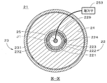
도8은 본 발명의 제6실시형태에 관한 금속공기전지(21)을 나타낸 종단면도이다. 금속공기전지(21)는 원통형이며, 도8은 금속공기전지(21)의 중심축(J1)을 포함하는 단면을 나타낸다. 도9는 금속공기전지(21)를 도8의 IX-IX 위치에서 절단한 횡단면도이다. 도8 및 도9에 나타나 있는 바와 같이 금속공기전지(21)는 정극(22), 부극(23), 전해질층(24) 및 공기 유입관(25)을 구비하는 이차전지로서, 중심축(J1)으로부터 지름방향의 외측을 향하여 공기 유입관(25), 정극(22), 전해질층(24) 및 부극(23)이 순차적으로 동심원 모양으로 배치된다. 바꾸어 말하면 금속공기전지(21)는 외주에 부극(23)이 배치되고, 내주에 정극(22)이 배치되는 원통형이다.8 is a longitudinal sectional view showing a metal air battery 21 according to a sixth embodiment of the present invention. The metal air battery 21 is cylindrical, and FIG. 8 shows a cross section including the central axis J1 of the metal air battery 21. FIG. 9 is a cross-sectional view of the metal air battery 21 cut at the IX-IX position in FIG. 8. As shown in FIGS. 8 and 9, the metal-air battery 21 is a secondary battery including a positive electrode 22, a negative electrode 23, an electrolyte layer 24, and an air inlet pipe 25. The central axis J1 ), The air inflow pipe 25, the positive electrode 22, the electrolyte layer 24, and the negative electrode 23 are sequentially arranged concentrically from the radially outward direction. In other words, the metal-air battery 21 has a cylindrical shape in which the negative electrode 23 is arranged on the outer circumference and the positive electrode 22 is arranged on the inner circumference.

정극(22)은 유저 원통형의 다공질 부재이며, 각각 유저 원통형의 정극 지지부(221), 정극 도전층(222) 및 정극 촉매층(223)을 구비한다. 금속공기전지(21)는 하기의 전해액에 대한 발액성(본 실시형태에서는 수계 전해액에 대한 방수성)을 구비하는 다공질의 발액층(229)을 추가로 구비하고, 발액층(229)은 정극(22)에 설치된다. 구체적으로 발액층(229)은 정극 지지부(221)의 외측면 및 외저면 상에 적층된다. 또한 정극 도전층(222)은 발액층(229)의 외측면 및 외저면 상에 적층되고, 정극 촉매층(223)은 정극 도전층(222)의 외측면 및 외저면 상에 적층된다. 정극(22)에서는 정극 도전층(222)의 외측면의 일부에 정극 촉매층(223)을 대신하여 정극 집전체(224)이 설치되고, 도8에 나타나 있는 바와 같이 정극 집전체(224)의 상단에 정극 집전단자(225)가 접속된다. 정극(22) 및 정극 집전체(224)에 탄소(C)는 포함되지 않는다.The positive electrode 22 is a user cylindrical porous member, and includes a user cylindrical positive electrode support 221, a positive electrode conductive layer 222, and a positive electrode catalyst layer 223, respectively. The metal-air battery 21 further includes a porous liquid repellent layer 229 having liquid repellency for the following electrolyte solution (in this embodiment, waterproof to an aqueous electrolyte solution), and the liquid repellent layer 229 has a positive electrode 22. It is installed in). Specifically, the liquid repellent layer 229 is laminated on the outer surface and the outer bottom surface of the positive electrode support portion 221. In addition, the positive electrode conductive layer 222 is laminated on the outer and outer bottom surfaces of the liquid repellent layer 229, and the positive electrode catalyst layer 223 is laminated on the outer and outer bottom surfaces of the positive electrode conductive layer 222. In the positive electrode 22, a positive electrode current collector 224 is provided on a part of the outer surface of the positive electrode conductive layer 222 in place of the positive electrode catalyst layer 223, and as shown in FIG. 8, an upper end of the positive electrode current collector 224. The positive electrode current collector terminal 225 is connected to it. Carbon (C) is not included in the positive electrode 22 and the positive electrode current collector 224.

정극 지지부(221)는 상기의 정극 지지부(121)와 마찬가지로, 예를 들면 알루미나(산화알루미늄: Al2O3)나 지르코니아(zirconia) 등의 세라믹, 또는 스테인레스강 등의 금속으로 형성된 다공질 부재이며, 본 실시형태에서 정극 지지부(221)는 절연체인 알루미나로 형성된다. 또한 정극 지지부(221)는 상기 정극 지지부(121)와 동일한 방법으로 형성된다. 정극 지지부(221) 상의 정극 도전층(222)은 상기의 정극 도전층(122)과 같이 형성되고, 정극 촉매층(223)은 상기의 정극 촉매층(123)과 같이 형성된다. The positive electrode support 221, like the positive electrode support 121 of the, for example, alumina: a porous member made of a metal such as a ceramic, or stainless steel such as (aluminum oxide Al 2 O 3) or zirconia (zirconia), In this embodiment, the positive electrode support portion 221 is formed of alumina as an insulator. In addition, the positive electrode support 221 is formed in the same manner as the positive electrode support 121. The positive electrode conductive layer 222 on the positive electrode support 221 is formed like the positive electrode conductive layer 122, and the positive electrode catalyst layer 223 is formed like the positive electrode catalyst layer 123.

또한 정극 지지부(221)와 정극 도전층(222) 사이에 배치되는 발액층(229)은 방수성을 구비하는 재료로 형성되고, 정극 도전층(222) 형성시 고온이 될 경우에는 높은 내열성을 구비하는 세라믹계 재료(예를 들면 산화물 세라믹)가 사용된다. 본 실시형태에서는 실리카(이산화규소: SiO2)나 실리카 복합 재료로 형성된 다공질막이 발액층(229)으로써 사용된다. 또한 방수성을 구비하지 않는 다공질 부재에 포화플루오로알킬기(특히 트리플루오로메틸기(CF3-)), 알킬시릴기, 플루오로시릴기, 장쇄알킬기 등의 관능기를 구비하는 물질을 피복함으로써 발액층(229)을 형성하여도 좋다.In addition, the liquid-repellent layer 229 disposed between the positive electrode support portion 221 and the positive electrode conductive layer 222 is formed of a material having waterproofness, and has a high heat resistance when the positive electrode conductive layer 222 is formed at a high temperature. Ceramic-based materials (eg oxide ceramics) are used. In this embodiment, a porous film formed of silica (silicon dioxide: SiO 2 ) or a silica composite material is used as the liquid repellent layer 229. A liquid repellent layer is formed by coating a porous member having no waterproof property with a substance having functional groups such as saturated fluoroalkyl group (particularly trifluoromethyl group (CF 3- )), alkylsilyl group, fluorosilyl group, and long chain alkyl group. 229) may be formed.

도8 및 도9에 나타나 있는 바와 같이, 부극(23)은 유저 원통형인 부극 지지부(231), 및 부극 지지부(231)의 내측면 및 내저면 상에 적층된 유저 원통형의 부극 도전층(232)을 구비한다. 부극 지지부(231)는 금속 등의 도전성 재료(본 실시형태에서는 스테인레스강)로 형성된 부극 집전체이며, 부극 지지부(231)의 외측면에는 도8에 나타나 있는 바와 같이 부극 집전단자(233)가 설치된다. 부극 도전층(232)은 아연(Zn)이나 리튬(Li) 등의 금속, 또는 당해 금속을 포함하는 합금으로 형성된 얇은 도전막이며, 본 실시형태에서 부극 도전층(232)은 아연 또는 아연합금으로 형성된다. 부극 도전층(232)의 형성은 예를 들면 슬러리 코트법으로 이루어진다.As shown in FIGS. 8 and 9, the negative electrode 23 is a user cylindrical negative electrode support 231, and a user cylindrical negative electrode conductive layer 232 laminated on the inner and inner bottom surfaces of the negative electrode support 231. It is provided. The negative electrode support 231 is a negative electrode current collector formed of a conductive material such as metal (stainless steel in this embodiment), and a negative electrode current collector terminal 233 is provided on the outer surface of the negative electrode support 231 as shown in FIG. 8. do. The negative electrode conductive layer 232 is a thin conductive film formed of a metal such as zinc (Zn) or lithium (Li), or an alloy containing the metal. In the present embodiment, the negative electrode conductive layer 232 is made of zinc or zinc alloy. Is formed. The negative electrode conductive layer 232 is formed by, for example, a slurry coating method.

전해질층(24)은 수계 전해질로 형성되고, 본 실시형태에서는 수산화칼륨(KOH)을 포함하는 전해액(전해질 용액이라고도 불린다)이 정극(22)과 부극(23) 사이에 충전(배치)됨으로써 형성된다. 전해질층(24)은 정극(22)의 정극 촉매층(223), 정극 집전체(224), 및 부극(23)의 부극 도전층(232)에 접한다. 전해질층(24)의 상면은 정극 지지부(221)의 외측면 및 부극 지지부(231)의 내측면에 접하는 원환형 중간마개(251)로 폐쇄되고, 중간마개(251)의 상방에는 중간마개(251)와 동일한 형상의 바깥마개(252)가 설치되어서 유저 원통형의 부극(23)의 상부개구가 폐쇄된다. 또 전해질층(24)에 포함된 전해액은 다른 수계 전해액이나 비수계(예를 들면 유기용제계) 전해액이어도 좋다.The electrolyte layer 24 is formed of an aqueous electrolyte, and in this embodiment, an electrolyte solution (also called an electrolyte solution) containing potassium hydroxide (KOH) is formed by filling (disposing) between the positive electrode 22 and the negative electrode 23. . The electrolyte layer 24 is in contact with the positive electrode catalyst layer 223 of the positive electrode 22, the positive electrode current collector 224, and the negative electrode conductive layer 232 of the negative electrode 23. The upper surface of the electrolyte layer 24 is closed by an annular intermediate plug 251 which is in contact with the outer surface of the positive electrode support 221 and the inner surface of the negative electrode support 231, and the intermediate plug 251 above the intermediate plug 251. The outer plug 252 having the same shape as) is provided so that the upper opening of the negative electrode 23 of the user cylinder is closed. The electrolyte solution contained in the electrolyte layer 24 may be another aqueous electrolyte solution or a non-aqueous (for example, organic solvent) electrolyte solution.

공기 유입관(25)은 유저 원통형인 정극(22)의 내측에 배치되고, 공기 유입관(25)의 하단은 정극(22)의 정극 지지부(221)의 바닥부 근방에 위치한다. 공기 유입관(25)의 상단은 공기로부터 수분 및 이산화탄소를 제거하는 제거부(253)에 접속된다. 제거부(253)에서는 막분리법 또는 흡착에 의하여 공기 중의 수분 및 이산화탄소의 제거가 이루어진다. 제거부(253)로부터의 공기(즉 수분 및 이산화탄소가 제거된 공기)는 공기 유입관(25)에 의하여 정극(22) 내측의 바닥부 근방에 인도되어, 정극(22)에 공급되면서 정극(22)의 내측면에 따라 상승하여 정극(22)의 상부 개구를 통해 외부로 배출된다. 금속공기전지(21)에서는 공기 유입관(25)이 제거부(253)로부터의 공기를 정극(22)에 공급하는 가스 공급부가 된다. 정극(22)에 공급된 공기는 각각이 다공질 부재인 정극 지지부(221), 발액층(229) 및 정극 도전층(222)을 통과하여 정극 촉매층(223)에 공급된다. 금속공기전지(21)에서는 원칙적으로 다공질의 정극 촉매층(223)에 공기와 전해액의 계면이 형성된다.The air inflow pipe 25 is disposed inside the positive electrode 22, which is a user cylinder, and the lower end of the air inflow pipe 25 is located near the bottom of the positive electrode support 221 of the positive electrode 22. The upper end of the air inlet pipe 25 is connected to a removal unit 253 which removes water and carbon dioxide from the air. The removal unit 253 removes water and carbon dioxide from the air by membrane separation or adsorption. Air from the removal unit 253 (that is, air from which moisture and carbon dioxide have been removed) is guided by the air inlet pipe 25 near the bottom of the inside of the positive electrode 22 and supplied to the positive electrode 22 while being supplied to the positive electrode 22. Ascending along the inner surface of the c), it is discharged to the outside through the upper opening of the positive electrode 22. In the metal air battery 21, the air inlet pipe 25 is a gas supply unit for supplying air from the removal unit 253 to the positive electrode 22. Air supplied to the positive electrode 22 is supplied to the positive electrode catalyst layer 223 through the positive electrode support part 221, the liquid repellent layer 229, and the positive electrode conductive layer 222, each of which is a porous member. In the metal-air battery 21, an interface between air and electrolyte is formed in the porous positive electrode catalyst layer 223 in principle.

도8의 금속공기전지(21)에서 방전이 이루어질 때에는 부극 집전단자(233)와 정극 집전단자(225)가 부하(예를 들면 조명기구 등)을 통하여 전기적으로 접속된다. 부극(23)에서는 부극 도전층(232)에 포함된 금속이 산화되어 금속이온(여기에서는 아연이온(Zn2+))이 생성되고, 전자는 부극 집전단자(233), 정극 집전단자(225) 및 정극 집전체(224)를 통하여 정극(22)에 공급된다. 정극(22)에서는 공기 유입관(25)을 통하여 공급된 공기 중의 산소가 부극(23)으로부터 공급된 전자에 의하여 환원되어 산소이온(O2-)이 생성된다. 정극(22)에서는 정극 촉매층(223)에 포함된 정극 촉매에 의하여 산소이온의 생성(즉 산소의 환원반응)이 촉진되기 때문에, 당해 환원반응에 소비되는 에너지에 의한 과전압이 작아져서 금속공기전지(21)의 방전전압을 높일 수 있다. 정극(22)에서 생성된 산소이온은 부극(23)으로부터 전해질층(24) 속으로 용해된 금속이온과 결합하고, 이에 따라 금속 산화물이 생성된다. When discharge is performed in the metal-air battery 21 of FIG. 8, the negative electrode current collector terminal 233 and the positive electrode current collector terminal 225 are electrically connected through a load (for example, a lighting device). In the negative electrode 23, a metal contained in the negative electrode conductive layer 232 is oxidized to metal ions (in this case, zinc ions (Zn 2 +)) is generated and, e is a negative electrode current collecting terminal 233, the positive electrode current collecting terminal (225) And the positive electrode 22 through the positive electrode current collector 224. In the positive electrode 22, oxygen in the air supplied through the air inlet pipe 25 is reduced by electrons supplied from the negative electrode 23 to generate oxygen ions O 2 −. In the positive electrode 22, since the production of oxygen ions (ie, a reduction reaction of oxygen) is promoted by the positive electrode catalyst included in the positive electrode catalyst layer 223, the overvoltage caused by the energy consumed in the reduction reaction is reduced, so that the metal air battery ( The discharge voltage of 21 can be increased. Oxygen ions generated in the positive electrode 22 combine with the metal ions dissolved from the negative electrode 23 into the electrolyte layer 24, thereby producing metal oxides.

한편 금속공기전지(21)에서 충전이 이루어질 때에는 부극 집전단자(233)와 정극 집전단자(225) 사이에 전압이 부여되고, 정극(22)에서 금속 산화물이 분해되는 동시에, 산소이온으로부터 정극 집전체(224)를 통하여 정극 집전단자(225)에 전자가 공급되어 산소가 발생한다. 부극(23)에서는 부극 집전단자(233)로 공급된 전자에 의하여 금속이온이 환원되어 부극 도전층(232)의 표면에 금속이 석출된다. 정극(22)에서는 정극 촉매층(223)에 포함된 정극 촉매에 의하여 산소 발생이 촉진되기 때문에, 과전압이 작아져서 금속공기전지(21)의 충전전압을 낮출 수 있다.On the other hand, when charging is performed in the metal-air battery 21, a voltage is applied between the negative electrode current collector terminal 233 and the positive electrode current collector terminal 225, the metal oxide is decomposed at the positive electrode 22, and the positive electrode current collector from oxygen ions. The electrons are supplied to the positive electrode current collector terminal 225 through 224 to generate oxygen. In the negative electrode 23, metal ions are reduced by electrons supplied to the negative electrode current collector terminal 233, and metal is deposited on the surface of the negative electrode conductive layer 232. In the positive electrode 22, since the generation of oxygen is promoted by the positive electrode catalyst included in the positive electrode catalyst layer 223, the overvoltage is reduced, so that the charging voltage of the metal-air battery 21 can be lowered.

그런데 일반적인 금속공기전지의 정극은 도전성을 얻기 위하여 탄소를 주체로 하고, 당해 탄소에 산소의 환원반응을 촉진하는 정극 촉매가 첨가되어 있다. 그러나 이러한 금속공기전지에서는, 방전시에 생성되는 금속이온이 금속탄산염으로 정극 상에 석출되고, 충전시에 금속탄산염을 전기분해하여 이온화하기 위하여 큰 에너지가 필요하기 때문에 충전전압이 높아져 버린다.By the way, the positive electrode of the general metal-air battery mainly uses carbon as a main material for obtaining conductivity, and a positive electrode catalyst for promoting the reduction reaction of oxygen is added to the carbon. However, in such a metal-air battery, the metal ions generated at the time of discharge are precipitated on the positive electrode with metal carbonate, and the charging voltage increases because a large amount of energy is required to electrolyze and ionize the metal carbonate during charging.

이에 대하여 본 실시형태에 관한 금속공기전지(21)에서는, 페로브스카이트형 산화물로 형성된 정극 도전층(222) 상에 정극 촉매층(223)을 형성함으로써 탄소를 함유하지 않는 정극(22)을 실현할 수 있다. 이에 따라 방전시 정극(22) 상에 금속탄산염이 생성되는 것을 방지할 수 있고, 금속공기전지(21)의 충전전압을 낮출 수 있다. 또한 정극 도전층(222)이 도전성이 높은 란탄계 페로브스카이트형 산화물을 포함하고 있기 때문에 금속공기전지(21)의 방전전압을 높일 수 있다. 또한 정극 도전층(222)에 포함된 페로브스카이트형 산화물이 화학식A1-xBO3(0.9≤1-x<1.0)으로 나타나는 것이기 때문에, 정극 도전층(222)이 수분에 의하여 열화해 버리는 것을 방지하고, 금속공기전지(21)의 내구성을 향상시킬 수 있다.In contrast, in the metal-air battery 21 according to the present embodiment, the positive electrode 22 containing no carbon can be realized by forming the positive electrode catalyst layer 223 on the positive electrode conductive layer 222 formed of the perovskite oxide. have. Accordingly, the metal carbonate can be prevented from being generated on the positive electrode 22 during discharge, and the charging voltage of the metal air battery 21 can be lowered. In addition, since the positive electrode conductive layer 222 contains a highly conductive lanthanum perovskite oxide, the discharge voltage of the metal-air battery 21 can be increased. In addition, since the perovskite oxide contained in the positive electrode conductive layer 222 is represented by the general formula A 1-x BO 3 (0.9 ≦ 1-x <1.0), the positive electrode conductive layer 222 deteriorates due to moisture. Can be prevented and the durability of the metal-air battery 21 can be improved.

금속공기전지(21)에서는 정극(22)의 정극 도전층(222)이 정극 지지부(221)에 의하여 지지(담지)되는 얇은 도전막이기 때문에 비교적 고가인 페로브스카이트형 산화물의 사용량을 줄일 수 있다. 따라서 금속공기전지(21)의 제조비용을 절감할 수 있다.In the metal air battery 21, since the positive electrode conductive layer 222 of the positive electrode 22 is a thin conductive film supported (supported) by the positive electrode support part 221, the amount of the relatively expensive perovskite oxide can be reduced. . Therefore, the manufacturing cost of the metal air battery 21 can be reduced.

또한 금속공기전지(21)에서는 전해질층(24)에 포함된 전해액에 대하여 발액성을 가진 발액층(229)이, 정극 도전층(222) 및 정극 촉매층(223)의, 전해질층(24)과 반대측에 설치됨으로써, 가령 전해액이 정극 촉매층(223) 및 정극 도전층(222)을 침투(통과)하더라도 전해액이 정극 지지부(221)의 내측으로(즉 공기 유입관(25)의 근방에) 누출되는 것을 방지할 수 있다. 또한 발액층(229)이 다공질 부재이므로 정극 도전층(222) 및 정극 촉매층(223)에 대하여 공기를 공급하면서 전해액의 누출(누액)을 방지할 수 있다.In the metal-air battery 21, the liquid-repellent layer 229 having liquid repellency with respect to the electrolyte contained in the electrolyte layer 24 includes the electrolyte layer 24 of the positive electrode conductive layer 222 and the positive electrode catalyst layer 223. By being installed on the opposite side, even if the electrolyte solution penetrates (passes) the positive electrode catalyst layer 223 and the positive electrode conductive layer 222, the electrolyte solution leaks inside the positive electrode support part 221 (that is, near the air inlet pipe 25). Can be prevented. In addition, since the liquid repellent layer 229 is a porous member, it is possible to prevent leakage (leakage) of the electrolyte while supplying air to the positive electrode conductive layer 222 and the positive electrode catalyst layer 223.

상기한 바와 같이 금속공기전지(21)는 부극(23) 및 정극(22)이 각각 외주 및 내주에 배치되는 원통형이기 때문에, 금속공기전지(21)의 대형화가 요구될 경우에도 부극 도전층(232)이나 정극 도전층(222)과 같은 박막형의 층을 용이하게 형성할 수 있다. 즉 금속공기전지(21)의 대형화에 용이하게 대응할 수 있다. 또한 부극(23), 정극(22), 전해질층(24) 및 발액층(229)이 동심을 갖는 유저 원통형이므로 정극(22)의 측면 및 저면 양방으로 전해액이 누출되는 것을 방지할 수 있다. 또한 공기 유입관(25)을 통하여 이산화탄소가 제거된 공기가 정극(22)에 공급됨으로써 공기 중의 이산화탄소와 금속이온이 반응하여 정극(22)에 금속탄산염이 부착되는 것이 방지된다.As described above, the metal air battery 21 has a cylindrical shape in which the negative electrode 23 and the positive electrode 22 are disposed on the outer circumference and the inner circumference, respectively. ) And a thin film layer such as the positive electrode conductive layer 222 can be easily formed. In other words, it is possible to easily cope with the increase in size of the metal-air battery 21. In addition, since the negative electrode 23, the positive electrode 22, the electrolyte layer 24, and the liquid-repellent layer 229 have concentric user cylinders, the electrolyte solution can be prevented from leaking to both the side and bottom surfaces of the positive electrode 22. In addition, the carbon dioxide is removed through the air inlet pipe 25 is supplied to the positive electrode 22, the carbon dioxide in the air and the metal ion is prevented from adhering the metal carbonate to the positive electrode 22.

금속공기전지(21)에서는 전해질층(24)의 수계전해액에 무기 미립자(필러)가 첨가되어도 좋다. 무기 미립자로는 알루미나나 이산화규소(SiO2), 이산화티탄(TiO2), 제올라이트, 페로브스카이트형 산화물 등의 무기 산화물이 바람직하고, 특히 Si비가 높은(예를 들면 Si/Al이 2 이상인) 제올라이트 입자가 더욱 바람직하다. 전해질층(24)의 전해액이 무기 미립자를 포함함으로써, 금속공기전지(21)의 내부저항이 감소하여 전지용량이 증대함과 더불어 금속공기전지(21)로부터의 누액이 방지된다. 또 후술하는 제7 내지 제10실시형태에 관한 금속공기전지에서도 전해질층에 포함된 전해액이 무기 미립자를 포함함으로써, 상기와 동일한 효과(즉 전지용량의 증대 및 누액방지)를 얻을 수 있다.In the metal air battery 21, inorganic fine particles (filler) may be added to the aqueous electrolyte solution of the electrolyte layer 24. As the inorganic fine particles, inorganic oxides such as alumina, silicon dioxide (SiO 2 ), titanium dioxide (TiO 2 ), zeolite, and perovskite-type oxides are preferable, and particularly high Si ratios (for example, Si / Al of 2 or more) Zeolite particles are more preferred. When the electrolyte solution of the electrolyte layer 24 contains inorganic fine particles, the internal resistance of the metal air battery 21 is reduced, battery capacity is increased, and leakage from the metal air battery 21 is prevented. In the metal-air battery according to the seventh to tenth embodiments described later, the same effect as that described above (that is, increase in battery capacity and leakage prevention) can be obtained when the electrolyte solution contained in the electrolyte layer contains inorganic fine particles.

도10은 금속공기전지(21)의 다른 예를 나타낸 도면이고, 도9에 대응하는 도이다. 도10의 금속공기전지(21)에서는 정극 도전층(222)은 정극 지지부(221)의 외측면 및 외저면 상에 적층되고, 정극 촉매층(223a)은 정극 도전층(222)의 외측면 및 외저면 상에 적층된다. 즉 도10의 정극(22a)에서는 도9의 발액층(229)이 생략된다. 또한 정극 촉매층(223a)은 프랙탈 구조(fractal 構造)를 구비하고 있다. 구체적으로는 정극 도전층(222)의 외측면 및 외저면의 각 면에 촉매(여기에서는 이산화망간)가 당해 면에 거의 수직이 되는 다수의 침형(針型)으로 형성되어 있고, 이것에 의하여 정극 촉매층(223a)이 방수성을 구비한다. 정극 촉매층(223a)은 예를 들면 수열합성법으로 형성된다.FIG. 10 is a diagram showing another example of the metal-air battery 21, and corresponds to FIG. In the metal-air battery 21 of FIG. 10, the positive electrode conductive layer 222 is laminated on the outer side and the outer bottom of the positive electrode support part 221, and the positive electrode catalyst layer 223a is the outer side and the outer side of the positive electrode conductive layer 222. Laminated on the bottom. That is, in the positive electrode 22a of FIG. 10, the liquid repellent layer 229 of FIG. 9 is omitted. The positive electrode catalyst layer 223a has a fractal structure. Specifically, catalysts (here, manganese dioxide) are formed on the outer and outer bottom surfaces of the positive electrode conductive layer 222 in a plurality of needle-shaped shapes that are substantially perpendicular to the surface, whereby the positive electrode catalyst layer 223a is waterproof. The positive electrode catalyst layer 223a is formed by, for example, hydrothermal synthesis.

이와 같이 도10의 금속공기전지(21)에서는 정극 도전층(222)과 전해질층(24) 사이에 배치되는 정극 촉매층(223a)(의 촉매)이 프랙탈 구조를 구비한다. 이에 따라 정극 촉매층(223a)이 발액층을 겸하므로 전해액이 내측(정극 도전층(222) 측)으로 이동하는 것을 차단하고, 그 결과 금속공기전지(21)의 구조를 간소화하면서 전해액이 정극(22a)을 침투하여 누출되는 것이 방지된다. 또한 정극 촉매층(223a)에 전해액과 공기의 계면이 보다 확실하게 형성됨으로써 산소환원반응을 더욱 촉진할 수 있다. 또 정극 도전층(222)의 외측면의 일부(즉 정극 촉매층(223a)이 형성되지 않는 부위)에는 정극 집전체(224)가 설치되는데, 정극 집전체(224)가 촘촘하게 형성되기 때문에 전해액이 정극 집전체(224)를 침투하는 경우는 없다. 즉 정극 촉매층(223a)은 불투액성 부재와 함께 정극 도전층(222)의 외측면 및 외저면의 전체를 덮고 있기 때문에 전해액이 누출되는 것이 방지된다. 물론 정극 도전층(222)의 외측면 및 외저면의 전체에 정극 촉매층(223a)이 형성되고, 정극 집전체(224)가 정극 도전층(222)의 상부나 내측에 설치되어도 좋다.As described above, in the metal-air battery 21 of FIG. 10, the cathode catalyst layer 223a (catalyst) disposed between the cathode conductive layer 222 and the electrolyte layer 24 has a fractal structure. Accordingly, since the positive electrode catalyst layer 223a also serves as a liquid repelling layer, the electrolyte solution is prevented from moving to the inner side (the positive electrode conductive layer 222 side), and as a result, the electrolyte solution is positive electrode 22a while simplifying the structure of the metal air battery 21. ) Is prevented from penetrating and leaking. In addition, since the interface between the electrolyte and the air is more reliably formed in the cathode catalyst layer 223a, the oxygen reduction reaction can be further promoted. In addition, a part of the outer surface of the cathode conductive layer 222 (that is, a portion where the cathode catalyst layer 223a is not formed) is provided with a cathode current collector 224. Since the cathode current collector 224 is formed densely, the electrolyte solution is positive. There is no case where the current collector 224 penetrates. That is, since the positive electrode catalyst layer 223a covers the entire outer and outer bottom surfaces of the positive electrode conductive layer 222 together with the impermeable member, leakage of the electrolyte solution is prevented. Of course, the positive electrode catalyst layer 223a may be formed on the outer and outer bottom surfaces of the positive electrode conductive layer 222, and the positive electrode current collector 224 may be provided above or inside the positive electrode conductive layer 222.

또한 정극 도전층(222)의 외측면 및 외저면 상에, 정극 촉매층(223a)의 촉매가 다수의 섬모양(島模樣) 또는 다공질상(多孔質狀)으로 형성되어도 좋다. 이 경우에 정극 촉매층(223a)의 촉매 상에 방수성 재료가 코팅되고, 촉매가 노출될 때까지 방수성 재료의 표면이 깎인다. 이에 따라(예를 들면 마이크로미터 오더의) 다수의 섬모양 촉매 주위 또는 다공질상 촉매의 구멍부가 방수성 재료로 충전되어 정극 촉매층(223a)이 방수성을 구비하게 된다. 방수성 재료로서 예를 들면 테플론(등록상표) 등의 불소 수지나, 세라믹계 재료, 또는 포화 플루오로알킬기(특히 트리플루오로메틸기(CF3-)), 알킬시릴기, 플루오로시릴기, 장쇄알킬기 등의 관능기를 구비하는 물질이 사용된다. In addition, the catalyst of the positive electrode catalyst layer 223a may be formed in a plurality of island shapes or porous phases on the outer surface and the outer bottom surface of the positive electrode conductive layer 222. In this case, the waterproof material is coated on the catalyst of the positive electrode catalyst layer 223a, and the surface of the waterproof material is scraped until the catalyst is exposed. As a result, the pores of the porous catalyst around the plurality of island-like catalysts (for example, in a micrometer order) are filled with a waterproof material, and the cathode catalyst layer 223a is waterproof. Examples of the waterproofing material include fluorine resins such as Teflon (registered trademark), ceramic materials, or saturated fluoroalkyl groups (particularly trifluoromethyl groups (CF 3- )), alkylsilyl groups, fluorosilyl groups, and long chain alkyl groups. The substance which has a functional group, such as these, is used.

이와 같이 정극 도전층(222)과 전해질층(24) 사이에 배치되는 정극 촉매층(223a)에 촉매가 다수의 섬모양 또는 다공질상으로 형성된 경우에는, 전해액에 대하여 발액성을 가진 재료가 촉매간에 부여된다. 이에 따라 정극 촉매층(223a)이 발액층을 겸하므로 전해액이 내측으로 이동하는 것을 차단하고, 그 결과 금속공기전지(21)의 구조를 간소화하면서 전해액이 정극(22a)으로 침투하여 누출되는 것이 방지된다. 상기 정극 촉매층(223a)(프랙탈 구조를 구비하는 것을 포함한다)은 후술하는 제7 내지 제10실시형태에 채용되어도 좋다.As described above, when the catalyst is formed in a plurality of islands or porous phases in the positive electrode catalyst layer 223a disposed between the positive electrode conductive layer 222 and the electrolyte layer 24, a material having liquid repellency with respect to the electrolyte is provided between the catalysts. do. Accordingly, since the positive electrode catalyst layer 223a also serves as a liquid repellent layer, the electrolyte solution is blocked from moving inward, and as a result, the electrolyte solution penetrates into the positive electrode 22a and is prevented from leaking while simplifying the structure of the metal air battery 21. . The positive electrode catalyst layer 223a (including the one having a fractal structure) may be employed in the seventh to tenth embodiments described later.

다음으로 본 발명의 제7실시형태에 관한 금속공기전지에 대하여 설명한다. 도11 및 도12는 제7실시형태에 관한 금속공기전지(21a)의 종단면도 및 횡단면도이며, 도12는 금속공기전지(21a)를 도11의 XII-XII 위치에서 절단한 도이다. 도11 및 도12에서는 도면을 간소화하기 위하여 제거부(253를 나타내지 않았다(도13 내지 도15도 동일).Next, the metal-air battery which concerns on 7th Embodiment of this invention is demonstrated. 11 and 12 are longitudinal cross-sectional views and cross-sectional views of the metal air battery 21a according to the seventh embodiment, and FIG. 12 is a view in which the metal air battery 21a is cut at the XII-XII position in FIG. 11 and 12, the removal unit 253 is not shown for the sake of simplicity (Figs. 13 to 15 are also the same).

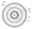
금속공기전지(21a)에서는 전해질층(24)과 부극(23) 사이에 또 하나의 전해질층(26)이 배치되고, 전해질층(24)과 전해질층(26) 사이에 분리벽층(27)이 배치된다. 분리벽층(27)은 박막형의 고체 전해질이며, 금속이온만 선택적으로 통과시킨다. 그 이외의 구성은 도8 및 도9에 나타낸 금속공기전지(21)와 같고, 이하의 설명에서는 대응하는 구성에 동일한 부호를 붙인다. 또한 2개의 전해질층(24, 26)을 구별하기 위하여 전해질층(24) 및 전해질층(26)을 각각 제1전해질층(24) 및 제2전해질층(26)이라고 한다.In the metal air battery 21a, another electrolyte layer 26 is disposed between the electrolyte layer 24 and the negative electrode 23, and a partition wall layer 27 is disposed between the electrolyte layer 24 and the electrolyte layer 26. Is placed. The partition wall layer 27 is a thin solid electrolyte and selectively passes only metal ions. Other configurations are the same as those of the metal-air battery 21 shown in Figs. 8 and 9, and in the following description, the same reference numerals are assigned to corresponding configurations. In addition, in order to distinguish the two electrolyte layers 24 and 26, the electrolyte layer 24 and the electrolyte layer 26 are referred to as a first electrolyte layer 24 and a second electrolyte layer 26, respectively.

도11 및 도12에 나타나 있는 바와 같이 제2전해질층(26)은 중심축(J1)을 중심으로 하는 유저 원통형이며, 부극(23)에 접한다. 분리벽층(27)도 유저 원통형이며, 제1전해질층(24) 및 제2전해질층(26)에 접한다. 제2전해질층(26)은 비수계(예를 들면 유기용제계) 또는 수계 전해액이 부극(23)과 분리벽층(27) 사이에 충전(배치)됨으로써 형성된다. 제2전해질층(26)의 상면은 제1전해질층(24)의 상면과 같이 원환형 중간마개(251, 도11에만 나타난다)로 폐쇄된다. 본 실시형태에서 제2전해질층(26)은 상기 전해액을 함침시킨 다공질 폴리머이며, 박막형의 고체 전해질인 분리벽층(27)은 제2전해질층(26)의 내측면 및 내저면 상에 제2전해질층(26)에 의하여 지지(담지)된다. 즉 제2전해질층(26)은 분리벽층(27)을 지지하는 분리벽지지층이기도 하다. 또한 분리벽층(27)으로는 화학식Lil +x+ yTi2 - xAlxP3 - ySiyO12로 나타나는 글라스세라믹스(LTAP)가 이용된다.As shown in Figs. 11 and 12, the second electrolyte layer 26 is a user cylindrical shape centering on the central axis J1 and is in contact with the negative electrode 23. Figs. The partition wall layer 27 is also user cylindrical and is in contact with the first electrolyte layer 24 and the second electrolyte layer 26. The second electrolyte layer 26 is formed by filling (disposing) the nonaqueous (for example, organic solvent) or aqueous electrolyte between the negative electrode 23 and the dividing wall layer 27. The upper surface of the second electrolyte layer 26 is closed by an annular intermediate plug 251 (only shown in Fig. 11), like the upper surface of the first electrolyte layer 24. In the present embodiment, the second electrolyte layer 26 is a porous polymer impregnated with the electrolyte solution, and the partition wall layer 27, which is a thin solid electrolyte, has a second electrolyte on the inner side and the inner bottom of the second electrolyte layer 26. Supported (supported) by layer 26. That is, the second electrolyte layer 26 is also a partition wall support layer that supports the partition wall 27. In addition, a glass ceramic (LTAP) represented by the formula Li l + x + y Ti 2 - x Al x P 3 - y Si y O 12 is used as the barrier layer 27.

금속공기전지(21a)에서 방전이 이루어질 때에는, 부극(23)의 부극 도전층(232)에 포함된 금속이 산화되어 금속이온이 생성되고, 전자는 부극 집전단자(233), 정극 집전단자(225) 및 정극 집전체(224)를 통하여 정극(22)에 공급된다. 부극 집전단자(233) 및 정극 집전단자(225)는 도11에만 나타난다. 정극(22)에서는 공기 유입관(25)을 통해 공급된 공기 중의 산소가 부극(23)으로부터 공급된 전자에 의하여 환원되어서 산소이온이 생성되고, 산소이온이 제1전해질층(24)에 포함된 물과 반응하여 수산화물이온(OH-)이 생성된다. 수산화물이온은 부극(23)으로부터 제2전해질층(26) 속으로 용해되어 제1전해질층(24)으로 이동한 금속이온과 함께 금속수산화물이 된다. 금속수산화물은 수용성이기 때문에 제1전해질층(24)의 수계 전해액에 녹는다.When discharge is performed in the metal air battery 21a, metal included in the negative electrode conductive layer 232 of the negative electrode 23 is oxidized to generate metal ions, and electrons are the negative electrode current collector terminal 233 and the positive electrode current collector terminal 225. And the positive electrode current collector 224 are supplied to the positive electrode 22. The negative electrode current collector terminal 233 and the positive electrode current collector terminal 225 appear only in FIG. In the positive electrode 22, oxygen in the air supplied through the air inlet pipe 25 is reduced by electrons supplied from the negative electrode 23 to generate oxygen ions, and oxygen ions are included in the first electrolyte layer 24. Reacts with water to form hydroxide ions (OH-). The hydroxide ions are dissolved into the second electrolyte layer 26 from the negative electrode 23 and become metal hydroxides together with the metal ions transferred to the first electrolyte layer 24. Since the metal hydroxide is water-soluble, it is dissolved in the aqueous electrolyte solution of the first electrolyte layer 24.

금속공기전지(21a)에서 충전이 이루어질 때에는, 부극 집전단자(233)와 정극 집전단자(225) 사이에 전압이 부여되고, 정극(22)의 수산화물이온으로부터 정극 집전단자(225)로 전자가 공급되어 물과 산소가 발생한다. 부극(23)에서는 부극 집전단자(233)에 공급되는 전자에 의하여 금속이온이 환원되어 부극 도전층(232)의 표면에 금속이 석출된다.When charging is performed in the metal-air battery 21a, a voltage is applied between the negative electrode current collector terminal 233 and the positive electrode current collector terminal 225, and electrons are supplied from the hydroxide ion of the positive electrode 22 to the positive electrode current collector terminal 225. Water and oxygen are generated. In the negative electrode 23, metal ions are reduced by electrons supplied to the negative electrode current collector terminal 233, and metal is deposited on the surface of the negative electrode conductive layer 232.

금속공기전지(21a)에서는 제6실시형태와 같이 정극(22)이 탄소를 함유하지 않기 때문에, 방전시 정극(22) 상에 금속탄산염이 생성되는 것을 방지할 수 있고, 금속공기전지(21a)의 충전전압을 낮출 수 있다. 금속공기전지(21a)에서는 특히 정극(22)과 부극(23) 사이에 분리벽층(27)을 설치함으로써, 충전시 부극(23) 상에 금속이 수지상으로 석출된 경우에 수지상으로 석출된 부위(소위 덴드라이트)가 정극(22)을 향하여 성장하는 것을 억제할 수 있다. 그 결과 덴드라이트가 정극(22)에 도달하여 단락이 발생하는 것을 방지할 수 있다. 또한 제2전해질층(26)에 의하여 분리벽층(27)을 지지함으로써 박막형의 분리벽층(27)의 설치를 용이하게 하고, 그 결과 금속공기전지(21a)의 소형화가 실현된다. 또한 분리벽층(27)이 박막형이기 때문에 분리벽층(27)을 두껍게 할 경우에 비해 이온 도전율이 증대된다.In the metal air battery 21a, as in the sixth embodiment, since the positive electrode 22 does not contain carbon, generation of metal carbonate on the positive electrode 22 during discharge can be prevented, and the metal air battery 21a can be prevented. Can lower the charging voltage. In the metal-air battery 21a, in particular, by providing the separating wall layer 27 between the positive electrode 22 and the negative electrode 23, the portion precipitated in the resinous phase when the metal precipitates in the resinous phase on the negative electrode 23 during charging ( The so-called dendrites can be suppressed from growing toward the positive electrode 22. As a result, the dendrites reach the positive electrode 22 and the short circuit can be prevented from occurring. In addition, by supporting the partition wall layer 27 by the second electrolyte layer 26, installation of the thin film partition wall 27 is facilitated, and as a result, the miniaturization of the metal-air battery 21a is realized. In addition, since the barrier layer 27 is a thin film type, the ion conductivity is increased as compared with the case where the barrier layer 27 is thickened.

또한 금속공기전지(21a)에서는 제1전해질층(24)의 전해액에 대하여 발액성을 가진 다공질의 발액층(229)이, 제1전해질층(24)과 접하는 정극(22)의 정극 지지부(221)와 정극 도전층(222) 사이에 설치된다. 이에 따라 정극 도전층(222) 및 정극 촉매층(223)에 공기를 공급하면서 제1전해질층(24)에 포함된 전해액이 누출되는 것을 방지할 수 있다.In the metal-air battery 21a, the porous liquid repellent layer 229 having liquid repellency with respect to the electrolyte solution of the first electrolyte layer 24, the positive electrode support portion 221 of the positive electrode 22 in contact with the first electrolyte layer 24 ) And the positive electrode conductive layer 222. Accordingly, the electrolyte contained in the first electrolyte layer 24 may be prevented from leaking while supplying air to the cathode conductive layer 222 and the cathode catalyst layer 223.

다음으로 본 발명의 제8실시형태에 관한 금속공기전지에 대하여 설명한다. 도13은 제8실시형태에 관한 금속공기전지(21b)의 횡단면도이다. 금속공기전지(21b)에서는 도11 및 도12에 나타나는 금속공기전지(21a)의 분리벽층(27, 고체 전해질)을 대신하여 세퍼레이터인 분리벽층(27a)이 설치된다. 그 이외의 구성은 도11 및 도12에 나타나는 금속공기전지(21a)와 같고, 이하의 설명에서는 대응하는 구성에 동일한 부호를 붙인다.Next, the metal-air battery which concerns on 8th Embodiment of this invention is demonstrated. 13 is a cross sectional view of the metal-air battery 21b according to the eighth embodiment. In the metal air battery 21b, a separator wall layer 27a serving as a separator is provided in place of the separator layer 27 (solid electrolyte) of the metal air battery 21a shown in Figs. Other configurations are the same as those of the metal-air battery 21a shown in Figs. 11 and 12, and in the following description, the same reference numerals are assigned to the corresponding configurations.

분리벽층(27a)은 세라믹이나 금속, 무기재료 또는 유기재료 등에 의하여 형성된 다공질 부재이며, 금속이온을 선택적으로 통과시키는 전해질을 구멍 내에 보전한다. 분리벽층(27a)의 형성은 압출성형, CIP 및 소성, 또는 HIP 등으로 이루어진다. 금속공기전지(21b)의 방전 및 충전시 반응은 제7실시형태에 관한 금속공기전지(21a)와 같다.The dividing wall layer 27a is a porous member formed of ceramic, metal, inorganic material, organic material, or the like, and holds electrolyte in the hole for selectively passing metal ions. The partition wall layer 27a is formed by extrusion molding, CIP and firing, or HIP. The reaction during discharging and charging of the metal air battery 21b is the same as that of the metal air battery 21a according to the seventh embodiment.

금속공기전지(21b)에서는 제6 및 제7실시형태와 같이 정극(22)이 탄소를 함유하지 않기 때문에, 방전시 정극(22) 상에 금속탄산염이 생성되는 것을 방지할 수 있고 금속공기전지(21b)의 충전전압을 낮출 수 있다. 또한 정극(22)과 부극(23) 사이에 분리벽층(27a)을 설치함으로써, 제7실시형태와 같이 충전시 부극(23) 상에 덴드라이트의 성장을 억제하고 단락이 발생하는 것을 방지할 수 있다. 또한 제1전해질층(24)의 전해액에 대하여 발액성을 가진 발액층(229)이 정극(22)에 설치됨으로써, 당해 전해액의 누출을 방지할 수 있다. 금속공기전지(21b)에서는 특히 세퍼레이터인 분리벽층(27a)의 설치에 제2전해질층(26)에 의한 지지가 필요하지 않으므로, 제2전해질층(26)의 재료선택의 자유도가 향상된다.In the metal air battery 21b, as in the sixth and seventh embodiments, since the positive electrode 22 does not contain carbon, generation of metal carbonate on the positive electrode 22 during discharge can be prevented and the metal air battery ( The charging voltage of 21b) can be lowered. In addition, by providing the separating wall layer 27a between the positive electrode 22 and the negative electrode 23, as in the seventh embodiment, it is possible to suppress the growth of dendrites on the negative electrode 23 during charging and to prevent the occurrence of a short circuit. have. Moreover, since the liquid repellent layer 229 which has liquid repellency with respect to the electrolyte solution of the 1st electrolyte layer 24 is provided in the positive electrode 22, leakage of the said electrolyte solution can be prevented. In the metal-air battery 21b, in particular, since the support by the second electrolyte layer 26 is not required for the installation of the separator wall 27a, which is a separator, the freedom of material selection of the second electrolyte layer 26 is improved.

다음으로 본 발명의 제9실시형태에 관한 금속공기전지에 대하여 설명한다. 도14는 제9실시형태에 관한 금속공기전지(21c)의 횡단면도이다. 금속공기전지(21c)는 제1전해질층(24)과 분리벽층(27) 사이에 분리벽지지층(271)을 구비하는 점을 제외하고, 도11 및 도12에 나타낸 금속공기전지(21a)와 같은 구성이고, 이하의 설명에서는 대응하는 구성에 동일한 부호를 붙인다.Next, the metal-air battery which concerns on 9th Embodiment of this invention is demonstrated. 14 is a cross sectional view of the metal-air battery 21c according to the ninth embodiment. The metal air battery 21c is provided with the metal air battery 21a shown in FIGS. 11 and 12 except that a partition wall support layer 271 is provided between the first electrolyte layer 24 and the partition wall layer 27. It is the same structure and in the following description, the same code | symbol is attached | subjected to the corresponding structure.

분리벽지지층(271)은 세라믹이나 금속, 무기재료 또는 유기재료 등에 의하여 압출성형, CIP 및 소성, 또는 HIP 등의 방법으로 형성된 다공질 부재이며, 구멍 내에 제1전해질층(24)의 수계의 전해액이 함침된다. 박막형의 고체 전해질인 분리벽층(27)은 분리벽지지층(271)의 외측면 및 외저면 상에 분리벽지지층(271)에 의하여 지지(담지)된다. 금속공기전지(21c)의 방전 및 충전시 반응은 제7실시형태에 관한 금속공기전지(21a)와 같다.The dividing wall support layer 271 is a porous member formed by ceramics, metals, inorganic materials or organic materials by extrusion molding, CIP and firing, or HIP, and the aqueous electrolyte solution of the first electrolyte layer 24 is formed in the pores. Impregnated The partition wall layer 27, which is a thin solid electrolyte, is supported (supported) by the partition wall support layer 271 on the outer surface and the outer bottom surface of the partition wall support layer 271. The reaction during discharging and charging of the metal air battery 21c is the same as that of the metal air battery 21a according to the seventh embodiment.

금속공기전지(21c)에서는 제6 내지 제8실시형태와 같이 정극(22)이 탄소를 함유하지 않기 때문에, 방전시 정극(22) 상에 금속탄산염이 생성되는 것을 방지할 수 있고 금속공기전지(21c)의 충전전압을 낮출 수 있다. 또한 정극(22)과 부극(23) 사이에 분리벽층(27) 및 분리벽지지층(271)을 설치함으로써, 제7실시형태와 같이 충전시 부극(23) 상에 덴드라이트의 성장을 억제하고 단락이 발생하는 것을 방지할 수 있다. 또한 제1전해질층(24)의 전해액에 대하여 발액성을 가진 발액층(229)이 정극(22)에 설치됨으로써, 당해 전해액의 누출을 방지할 수 있다. 상기한 바와 같이 금속공기전지(21c)에서는 분리벽층(27)이 분리벽지지층(271)에 의하여 지지되어 있고, 제2전해질층(26)에 의한 분리벽층(27)의 지지가 필요하지 않기 때문에, 제2전해질층(26)의 재료선택의 자유도가 향상된다.In the metal air battery 21c, as in the sixth to eighth embodiments, since the positive electrode 22 does not contain carbon, it is possible to prevent the formation of metal carbonate on the positive electrode 22 during discharge. The charging voltage of 21c) can be lowered. In addition, by providing the separating wall layer 27 and the separating wall support layer 271 between the positive electrode 22 and the negative electrode 23, the growth of dendrites on the negative electrode 23 during the charging as in the seventh embodiment is suppressed. This can be prevented from occurring. Moreover, since the liquid repellent layer 229 which has liquid repellency with respect to the electrolyte solution of the 1st electrolyte layer 24 is provided in the positive electrode 22, leakage of the said electrolyte solution can be prevented. As described above, in the metal-air battery 21c, the dividing wall layer 27 is supported by the dividing wall support layer 271, and the support of the dividing wall layer 27 by the second electrolyte layer 26 is not necessary. The degree of freedom of material selection of the second electrolyte layer 26 is improved.

다음으로 본 발명의 제10실시형태에 관한 금속공기전지에 대하여 설명한다. 도15는 제10실시형태에 관한 금속공기전지(21d)의 종단면도이다. 금속공기전지(21d)는 제2전해질층(26)이 제2전해질층(26)의 비수계 또는 수계 전해액을 순환시키는 순환기구(281)에 접속되는 점, 및 제1전해질층(24)이 제1전해질층(24)의 수계 전해액을 교환하는 교환기구에 접속되는 점을 제외하고, 도14에 나타낸 금속공기전지(21c)와 같은 구성이고, 이하의 설명에서는 대응하는 구성에 동일한 부호를 붙인다.Next, the metal-air battery which concerns on 10th Embodiment of this invention is demonstrated. 15 is a longitudinal cross-sectional view of a metal-air battery 21d according to the tenth embodiment. The metal-air battery 21d has a point where the second electrolyte layer 26 is connected to the circulation mechanism 281 for circulating the non-aqueous or aqueous electrolyte of the second electrolyte layer 26, and the first electrolyte layer 24 is Except for being connected to an exchange mechanism for exchanging the aqueous electrolyte solution of the first electrolyte layer 24, the structure is the same as that of the metal-air battery 21c shown in FIG. 14, and the same reference numerals are given to corresponding components in the following description. .

도15에 나타나 있는 바와 같이, 금속공기전지(21d)의 측부에는 제2전해질층(26)에 전해액을 공급하는 공급구(261), 및 제2전해질층(26)의 전해액이 배출되는 배출구(262)가 형성된다. 공급구(261) 및 배출구(262)는 관로(263)를 통하여 순환기구(281)에 접속되고, 배출구(262)로부터 배출된 전해액은 순환기구(281)를 거쳐 공급구(261)를 통하여 제2전해질층(26)에 다시 공급된다. 이에 따라 제2전해질층(26) 내에 전해액의 흐름이 발생하고, 금속공기전지(21d)의 충전시 덴드라이트의 발생이나 성장이 억제된다. 또한 순환기구(281)에는 필터가 설치되어 있어서 충전시 등에 부극 도전층(232)으로부터 금속의 박편이 탈피하였을 경우 등, 당해 금속이 순환기구(281)에 의해서 회수된다. As shown in FIG. 15, a supply port 261 for supplying an electrolyte solution to the second electrolyte layer 26 and a discharge port through which the electrolyte solution of the second electrolyte layer 26 is discharged are provided on the side of the metal-air battery 21d. 262 is formed. The supply port 261 and the discharge port 262 are connected to the circulation mechanism 281 through the conduit 263, and the electrolyte solution discharged from the discharge port 262 is formed through the supply port 261 via the circulation mechanism 281. It is supplied to the 2 electrolyte layer 26 again. As a result, the flow of the electrolyte solution occurs in the second electrolyte layer 26, and the generation and growth of dendrites during the charging of the metal-air battery 21d are suppressed. In addition, the circulation mechanism 281 is provided with a filter, so that the metal is recovered by the circulation mechanism 281, for example, when the metal flakes are released from the negative electrode conductive layer 232 at the time of charging or the like.

금속공기전지(21d)에는 제1전해질층(24)에 전해액을 공급하는 공급구(241), 및 제1전해질층(24)의 전해액이 배출되는 배출구(242)가 형성된다. 공급구(241)는 상기 교환기구의 공급기구(2821)에 접속되고, 공급기구(2821)로부터 새로운 전해액이 제1전해질층(24)에 공급된다. 배출구(242)는 교환기구의 회수기구(2822)에 접속되고, 제1전해질층(24)에서 배출된 전해액이 회수기구(2822)로 회수된다. 이에 따라 금속공기전지(21d)의 방전시 제1전해질층(24)의 전해액이 금속수산화물에 의하여 포화되는 것이 방지되고, 금속공기전지(21d)의 방전시간을 증대시킬 수 있다. 회수기구(2822)로 회수된 전해액으로부터 금속(부극 도전층(232)을 형성하는 금속)이 회수된다. 당해 금속은 금속공기전지의 부극 도전층(232)으로 다시 이용되어도 좋다.In the metal air battery 21d, a supply port 241 for supplying an electrolyte solution to the first electrolyte layer 24 and a discharge port 242 for discharging the electrolyte solution of the first electrolyte layer 24 are formed. The supply port 241 is connected to the supply mechanism 2821 of the exchange mechanism, and the new electrolyte is supplied to the first electrolyte layer 24 from the supply mechanism 2821. The discharge port 242 is connected to the recovery mechanism 2822 of the exchange mechanism, and the electrolyte solution discharged from the first electrolyte layer 24 is recovered to the recovery mechanism 2822. As a result, the electrolyte of the first electrolyte layer 24 is prevented from being saturated by the metal hydroxide when the metal air battery 21d is discharged, and the discharge time of the metal air battery 21d can be increased. Metal (metal forming the negative electrode conductive layer 232) is recovered from the electrolyte solution recovered by the recovery mechanism 2822. The metal may be used again as the negative electrode conductive layer 232 of the metal air battery.

이상과 같이 본 발명의 제6 내지 제10실시형태에 대하여 설명하였으나 상기 실시형태는 다양한 변경이 가능하다. As mentioned above, although 6th-10th embodiment of this invention was described, the said embodiment can be variously changed.

도8, 도11, 및 도13 내지 도15의 금속공기전지(21, 21a~21d)에서는 발액층(229)이 정극 도전층(222)과 정극 지지부(221) 사이에 설치되지만, 금속공기전지(21)의 설계에 따라서는 발액층(229)이 정극 지지부(221)의 내측(중심축(J1) 측)에 설치되어도 좋다.In the metal air batteries 21, 21a to 21d of FIGS. 8, 11, and 13 to 15, although the liquid repellent layer 229 is provided between the positive electrode conductive layer 222 and the positive electrode support portion 221, the metal air battery Depending on the design of (21), the liquid repellent layer 229 may be provided on the inner side (center axis J1 side) of the positive electrode support portion 221.

부극(23)에서 부극 지지부(231)는 반드시 도전성 재료로 형성될 필요는 없고, 부극 지지부(231)가 절연체로 형성될 경우에는 부극 집전단자(233)는 부극 지지부(231)를 관통하여 부극 도전층(232)에 전기적으로 접속된다. 또한 반드시 부극 지지부(231)가 설치될 필요는 없고, 아연이나 아연합금으로 부극(23) 전체가 형성되어도 좋다. 부극 도전층(232)은 방전시 산화되어 금속이온을 생성하는 금속을 포함한 다양한 재료로 형성되어도 좋다. In the negative electrode 23, the negative electrode support part 231 does not necessarily need to be formed of a conductive material. When the negative electrode support part 231 is formed of an insulator, the negative electrode current collector terminal 233 penetrates through the negative electrode support part 231 to conduct negative electrode conductivity. Is electrically connected to layer 232. In addition, the negative electrode support part 231 does not necessarily need to be provided, but the whole negative electrode 23 may be formed with zinc or a zinc alloy. The negative electrode conductive layer 232 may be formed of various materials including a metal which is oxidized during discharge to generate metal ions.

정극(22)에서는 정극 지지부(221)가 도전성 재료로 형성되어 있는 경우, 정극 집전체(224)를 생략하고 정극 지지부(221)의 내측면에 정극 집전단자(225)를 설치하여도 좋다. 또한 정극 도전층(222)이 어느 정도의 두께로 형성되어 있을 경우에는 정극 도전층(222)을 지지하는 정극 지지부(221)는 생략되어도 좋다. 이 경우에 정극 집전단자(225)는 정극 도전층(222)의 내측면에 설치된다.In the positive electrode 22, when the positive electrode support 221 is formed of a conductive material, the positive electrode current collector 224 may be omitted, and the positive electrode current collector terminal 225 may be provided on the inner surface of the positive electrode support 221. In addition, when the positive electrode conductive layer 222 is formed to some extent, the positive electrode support part 221 which supports the positive electrode conductive layer 222 may be abbreviate | omitted. In this case, the positive electrode current collector terminal 225 is provided on the inner side surface of the positive electrode conductive layer 222.

금속공기전지에서는 정극 지지부(221)의 재료와 정극 도전층(222)의 재료(즉 페로브스카이트형 산화물)가 혼합된 것으로 도전층을 형성하고, 당해 도전층 상에 정극 촉매층(223)을 형성하여 정극(22)으로 하여도 좋다. 또한 정극 지지부(221), 정극 도전층(222) 및 정극 촉매층(223)의 각 재료가 혼합된 것으로 정극(22)을 형성하여도 좋다. 어느 경우라도 정극(22)이 도전성을 가진 페로브스카이트형 산화물 및 산소환원반응을 촉진하는 촉매를 포함하면서 탄소를 포함하고 있지 않기 때문에, 금속공기전지의 방전시 부극(23)에 포함된 금속의 탄산염이 정극(22) 상에 생성되는 것을 방지할 수 있다.In the metal-air battery, a conductive layer is formed by mixing a material of the positive electrode support 221 and a material of the positive electrode conductive layer 222 (that is, a perovskite oxide), and a positive electrode catalyst layer 223 is formed on the conductive layer. The positive electrode 22 may be used. The positive electrode 22 may be formed by mixing the materials of the positive electrode support 221, the positive electrode conductive layer 222, and the positive electrode catalyst layer 223. In any case, since the positive electrode 22 contains a conductive perovskite oxide and a catalyst for promoting an oxygen reduction reaction and does not contain carbon, the metal contained in the negative electrode 23 during discharge of the metal-air battery Carbonate can be prevented from being formed on the positive electrode 22.

상기 실시형태에서는 정극(22)에 접하는 전해질층(24)에 수계 전해액이 사용되고 발액층(229, 또는 도10의 정극(22a)에서 발액층을 겸하는 정극 촉매층(223a))이 방수성을 구비할 경우에 대하여 설명하였으나, 비수계 전해액이 사용되는 경우에도 당해 전해액에 대하여 발액성을 가진 발액층을 정극에 설치함으로써 전해액이 정극을 침투하여 누출되는 것을 방지하는 것이 실현된다.In the above embodiment, when an aqueous electrolyte is used for the electrolyte layer 24 in contact with the positive electrode 22 and the liquid repellent layer 229 or the positive electrode catalyst layer 223a serving as the liquid repellent layer in the positive electrode 22a of FIG. 10 is provided with water resistance. As described above, even when a non-aqueous electrolyte is used, it is possible to prevent the electrolyte from penetrating the positive electrode and leaking by providing a liquid repellent layer having liquid repellency with respect to the electrolyte.

상기의 금속공기전지의 구조는 원통형 이외의 형상(예를 들면 평판형)의 금속공기전지에 적용되어도 좋다. 또한 상기 실시형태에서는 이차전지에 대하여 설명하였지만 상기의 금속공기전지의 구조는 1차전지나 연료전지에 적용되어도 좋다.The structure of the metal air battery described above may be applied to a metal air battery having a shape other than a cylindrical shape (for example, a flat plate type). Although the secondary battery has been described in the above embodiment, the structure of the metal air battery may be applied to the primary battery or the fuel cell.

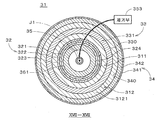
도16은 본 발명의 제11실시형태에 관한 금속공기전지(31)를 나타낸 종단면도이다. 금속공기전지(31)는 원통형이며, 도16은 금속공기전지(31)의 중심축(J1)을 포함하는 단면을 나타낸다. 도17은 금속공기전지(31)를 도16의 XVII-XVII 위치에서 절단한 횡단면도이다. 도16 및 도17에 나타나 있는 바와 같이 금속공기전지(31)는 정극층(32), 부극층(33) 및 전해질층(311)을 구비하는 이차전지다. 금속공기전지(31)는 공기 유입관(35), 또 하나의 전해질층(312) 및 보조 전극층(34)을 추가로 구비하고, 중심축(J1)으로부터 지름방향의 외측을 향하여 공기 유입관(35), 정극층(32), 전해질층(311), 부극층(33), 전해질층(312) 및 보조 전극층(34)이 순차적으로 동심원 모양으로 배치된다. 이하의 설명에서는 정극층(32)과 부극층(33) 사이의 전해질층(311)을 제1전해질층(311)이라고 부르고, 부극층(33)과 보조 전극층(34) 사이의 전해질층(312)을 제2전해질층(312)이라고 부른다. 16 is a longitudinal sectional view showing a metal air battery 31 according to the eleventh embodiment of the present invention. The metal air battery 31 is cylindrical, and FIG. 16 shows a cross section including the central axis J1 of the metal air battery 31. FIG. 17 is a cross-sectional view of the metal air battery 31 cut at the XVII-XVII position in FIG. 16. FIG. As shown in FIGS. 16 and 17, the metal-air battery 31 is a secondary battery including a positive electrode layer 32, a negative electrode layer 33, and an electrolyte layer 311. The metal air battery 31 further includes an air inlet tube 35, another electrolyte layer 312, and an auxiliary electrode layer 34, and the air inlet tube (1) is radially outward from the central axis J1. 35, the positive electrode layer 32, the electrolyte layer 311, the negative electrode layer 33, the electrolyte layer 312 and the auxiliary electrode layer 34 are sequentially arranged in a concentric shape. In the following description, the electrolyte layer 311 between the positive electrode layer 32 and the negative electrode layer 33 is called a first electrolyte layer 311, and the electrolyte layer 312 between the negative electrode layer 33 and the auxiliary electrode layer 34 is described. ) Is called the second electrolyte layer 312.

정극층(32)은 유저 원통형의 다공질 부재이며, 각각이 유저 원통형인 정극 도전층(322) 및 정극 촉매층(323), 및 후술하는 전해액에 대한 발액성(본 실시형태에서는 수계 전해액에 대한 방수성)을 가진 다공질의 발액층(321)을 구비한다. 구체적으로는 금속공기전지(31)에 중심축(J1)을 중심으로 하는 유저 원통형의 정극 지지부(361)가 설치되고, 발액층(321)은 정극 지지부(361)의 외측면 및 외저면 상에 적층된다. 또한 정극 도전층(322)은 발액층(321)의 외측면 및 외저면 상에 적층되고, 정극 촉매층(323)은 정극 도전층(322)의 외측면 및 외저면 상에 적층된다. 정극층(32)에는 정극 도전층(322)의 외측면 일부에 정극 촉매층(323)을 대신하여 정극 집전체(324)가 설치되고, 도16에 나타나 있는 바와 같이 정극 집전체(324)의 상단에 정극 집전단자(325)가 접속된다. 바람직하게는 정극층(32, 즉 발액층(321), 정극 도전층(322), 정극 촉매층(323) 및 정극 집전체(324))에 탄소(C)는 포함되지 않는다.The positive electrode layer 32 is a user cylindrical porous member, each of which has a user cylindrical positive electrode conductive layer 322 and a positive electrode catalyst layer 323, and liquid repellency for the electrolyte solution described later (water resistance to the aqueous electrolyte solution in this embodiment). It has a porous liquid repellent layer 321 having a. Specifically, a user cylindrical positive electrode support part 361 centering on the central axis J1 is provided on the metal air battery 31, and the liquid repellent layer 321 is formed on the outer surface and the outer bottom surface of the positive electrode support part 361. Are stacked. In addition, the positive electrode conductive layer 322 is laminated on the outer and outer bottom surfaces of the liquid repellent layer 321, and the positive electrode catalyst layer 323 is laminated on the outer and outer bottom surfaces of the positive electrode conductive layer 322. In the positive electrode layer 32, a positive electrode current collector 324 is provided on a part of the outer surface of the positive electrode conductive layer 322 in place of the positive electrode catalyst layer 323, and as shown in FIG. 16, an upper end of the positive electrode current collector 324. The positive electrode current collector terminal 325 is connected to it. Preferably, carbon (C) is not included in the positive electrode layer 32 (ie, the liquid repellent layer 321, the positive electrode conductive layer 322, the positive electrode catalyst layer 323, and the positive electrode current collector 324).

정극 지지부(361)는 상기의 정극 지지부(121, 221)와 같이 형성되고, 정극 도전층(322)은 상기의 정극 도전층(122, 222)과 같이 형성된다. 정극 촉매층(323)은 상기의 정극 촉매층(123, 223)과 같이 형성되고, 정극 지지부(361)와 정극 도전층(322) 사이에 배치되는 발액층(321)은 상기의 발액층(229)과 같이 형성된다.The positive electrode support part 361 is formed like the positive electrode support parts 121 and 221, and the positive electrode conductive layer 322 is formed like the positive electrode conductive layers 122 and 222. The positive electrode catalyst layer 323 is formed like the positive electrode catalyst layers 123 and 223, and the liquid repellent layer 321 disposed between the positive electrode support part 361 and the positive electrode conductive layer 322 is formed with the liquid repellent layer 229. Formed together.

도16 및 도17에 나타나 있는 바와 같이 부극층(33)은 원통형의 정극층(32)의 외측에 배치된 원통형의 부극 도전층(331)을 구비하고, 부극 도전층(331)의 상측 단부에는 도16에 나타나 있는 바와 같이 부극 집전단자(332)가 설치된다. 부극 도전층(331)은 아연(Zn)이나 리튬(Li) 등의 금속 또는 당해 금속을 포함하는 합금으로 형성된 다공질 부재이며, 본 실시형태에서 부극 도전층(331)은 아연 또는 아연합금으로 형성된다.As shown in FIGS. 16 and 17, the negative electrode layer 33 includes a cylindrical negative electrode conductive layer 331 disposed outside the cylindrical positive electrode layer 32, and is provided at an upper end of the negative electrode conductive layer 331. As shown in Fig. 16, a negative electrode current collector terminal 332 is provided. The negative electrode conductive layer 331 is a porous member formed of a metal such as zinc (Zn) or lithium (Li) or an alloy containing the metal. In this embodiment, the negative electrode conductive layer 331 is formed of zinc or zinc alloy. .

충전용 제3전극인 보조 전극층(34)은 원통형인 부극층(33)의 외측에 배치된 원통형의 보조 도전층(342)을 구비한다. 보조 도전층(342)은 금속 등의 도전성 재료(본 실시형태에서는 스테인레스강)로 형성된 다공질 부재다. 또한 도16에 나타나 있는 바와 같이 금속공기전지(31)에는 절연성 재료로 형성된 보조전극 지지부(371)가 설치된다. 보조전극 지지부(371)는 원통형의 상측 지지부(3711) 및 유저 원통형의 하측 지지부(3712)를 구비하고, 보조 도전층(342), 상측 지지부(3711) 및 하측 지지부(3712)의 지름은 같다. 보조 도전층(342)의 상단부는 상측 지지부(3711)에 고정되고, 하단부는 하측 지지부(3712)에 고정된다. 금속공기전지(31)에서는 보조 도전층(342) 및 보조전극 지지부(371)에 의하여 정극층(32), 부극층(33), 제1전해질층(311) 및 제2전해질층(312)을 내부에 수용하는 유저 원통형의 용기가 형성된다. 또 도16의 상하방향(중심축(J1) 방향)은 중력방향으로 한정된 것은 아니다.The auxiliary electrode layer 34, which is the third electrode for charging, includes a cylindrical auxiliary conductive layer 342 disposed outside the cylindrical negative electrode layer 33. The auxiliary conductive layer 342 is a porous member formed of a conductive material such as metal (in this embodiment, stainless steel). As shown in FIG. 16, the auxiliary metal support part 371 formed of an insulating material is provided in the metal-air battery 31. As shown in FIG. The auxiliary electrode support part 371 includes a cylindrical upper support part 3711 and a user cylindrical lower support part 3712, and the diameters of the auxiliary conductive layer 342, the upper support part 3711 and the lower support part 3712 are the same. The upper end of the auxiliary conductive layer 342 is fixed to the upper support part 3711, and the lower end is fixed to the lower support part 3712. In the metal air battery 31, the positive electrode layer 32, the negative electrode layer 33, the first electrolyte layer 311, and the second electrolyte layer 312 are formed by the auxiliary conductive layer 342 and the auxiliary electrode support 371. A user cylindrical container accommodated therein is formed. In addition, the up-down direction (center axis J1 direction) of FIG. 16 is not limited to the gravity direction.

보조 도전층(342)의 내측면(340)은 부극 도전층(331)의, 정극층(32)과 반대측의 외측면(330)에 대하여 균일한 간격으로 배치된다. 즉 보조 도전층(342)의 내측면(340) 상의 각 위치로부터 부극 도전층(331)의 외측면(330)까지의 거리(최단 거리)가 당해 내측면(340)의 전체에 걸쳐서 거의 동일하다. 또한 보조 도전층(342)의 외측면에는 보조전극 집전단자(343)가 접속됨과 함께, 외측면의 전체에 걸쳐서 발액층(321)과 동일한 발액층(341)이 형성된다. The inner side surface 340 of the auxiliary conductive layer 342 is disposed at uniform intervals with respect to the outer side surface 330 of the negative electrode conductive layer 331 opposite to the positive electrode layer 32. That is, the distance (shortest distance) from each position on the inner side surface 340 of the auxiliary conductive layer 342 to the outer side surface 330 of the negative electrode conductive layer 331 is substantially the same throughout the inner side surface 340. . In addition, the auxiliary electrode current collector terminal 343 is connected to the outer surface of the auxiliary conductive layer 342, and the same liquid repellent layer 341 as the liquid repellent layer 321 is formed over the entire outer surface.

제1전해질층(311)은 수계 전해질로 형성되고, 본 실시형태에서는 수산화칼륨(KOH)을 포함하는 전해액(예를 들면, 물 1리터 당 KOH를 8mol 용해시킨 8M-KOH수용액이다. 전해액은 전해질 용액으로도 불린다)이 정극층(32)과 부극층(33) 사이에 충전(배치)됨으로써 형성된다. 제1전해질층(311)은 정극층(32)의 정극 촉매층(323), 정극 집전체(324) 및 부극층(33)의 부극 도전층(331)에 접한다. 도16에 나타나 있는 바와 같이 제1전해질층(311)의 상면은 정극 지지부(361)의 외측면 및 보조전극 지지부(371)의 내측면에 접하는 원환형의 중간마개(351)에 의하여 폐쇄되고, 중간마개(351)의 상방에는 중간마개(351)와 동일한 형상의 바깥마개(352)가 설치되어, 중간마개(351)의 상방의 개구가 폐쇄된다. 또 제1전해질층(311)에 포함된 전해액은 다른 수계 전해액이나 비수계(예를 들면 유기용제계) 전해액이어도 좋다.The first electrolyte layer 311 is formed of an aqueous electrolyte, and in this embodiment, is an 8M-KOH aqueous solution in which 8 mol of KOH is dissolved per liter of water (for example, an electrolyte containing potassium hydroxide (KOH)). Also called a solution) is formed by filling (arrangement) between the positive electrode layer 32 and the negative electrode layer 33. The first electrolyte layer 311 is in contact with the positive electrode catalyst layer 323 of the positive electrode layer 32, the positive electrode current collector 324, and the negative electrode conductive layer 331 of the negative electrode layer 33. As shown in FIG. 16, the upper surface of the first electrolyte layer 311 is closed by an annular intermediate plug 351 in contact with the outer surface of the positive electrode support 361 and the inner surface of the auxiliary electrode support 371, The outer stopper 352 of the same shape as the intermediate stopper 351 is provided above the intermediate stopper 351, and the opening above the intermediate stopper 351 is closed. The electrolyte contained in the first electrolyte layer 311 may be another aqueous electrolyte solution or a non-aqueous (for example, organic solvent) electrolyte solution.

부극층(33)과 보조 전극층(34) 사이의 제2전해질층(312)은 세라믹이나 무기재료 또는 유기재료 등으로 형성된 다공질 부재(3121)를 구비하고, 다공질 부재(3121)는 압출성형, CIP 및 소성, 또는 HIP 등의 방법으로 성형된다. 도16에 나타나 있는 바와 같이 부극 도전층(331)의 하단부와 하측 지지부(3712) 사이의 간극을 통하여 제2전해질층(312)과 제1전해질층(311)이 연결되고, 다공질 부재(3121)의 구멍내에 제1전해질층(311)의 수계 전해액이 함침된다. 즉 제2전해질층(312)에도 전해액이 충전된다.The second electrolyte layer 312 between the negative electrode layer 33 and the auxiliary electrode layer 34 includes a porous member 3121 formed of a ceramic, an inorganic material, an organic material, or the like, and the porous member 3121 is formed by extrusion molding or CIP. And by firing or HIP. As shown in FIG. 16, the second electrolyte layer 312 and the first electrolyte layer 311 are connected through a gap between the lower end portion of the negative electrode conductive layer 331 and the lower support portion 3712, and the porous member 3121 is disposed. The aqueous electrolyte solution of the first electrolyte layer 311 is impregnated in the hole of. That is, the electrolyte is also filled in the second electrolyte layer 312.

공기 유입관(35)은 유저 원통형인 정극 지지부(361)의 내측에 배치되고, 공기 유입관(35)의 하단은 정극 지지부(361)의 바닥부 근방에 위치한다. 공기 유입관(35)의 상단은 공기로부터 수분 및 이산화탄소를 제거하는 제거부(353)에 접속된다. 제거부(353)에서는 막분리법 또는 흡착에 의하여 공기 중의 수분 및 이산화탄소의 제거가 이루어진다. 제거부(353)로부터의 공기(즉 수분 및 이산화탄소가 제거된 공기)는 공기 유입관(35)을 통하여 정극 지지부(361) 내측의 바닥부 근방에 인도되어, 다공질 부재인 정극 지지부(361)의 측부를 통하여 정극층(32)에 공급되면서, 정극 지지부(361)의 내측면에 따라 상승하여 정극 지지부(361)의 상부 개구를 통해 외부로 배출된다. 금속공기전지(31)에서는 공기 유입관(35)이 제거부(353)로부터의 공기를 정극층(32)에 공급하는 가스 공급부가 된다. 정극층(32)에 공급된 공기는 다공질 부재인 발액층(321) 및 정극 도전층(322)을 통과하여 정극 촉매층(323)에 공급된다. 금속공기전지(31)에서는 원칙적으로 다공질의 정극 촉매층(323)에 공기와 전해액의 계면이 형성된다.The air inflow pipe 35 is disposed inside the positive electrode support part 361 which is a user cylindrical shape, and the lower end of the air inflow pipe 35 is located near the bottom part of the positive electrode support part 361. The upper end of the air inlet pipe 35 is connected to a removal unit 353 for removing water and carbon dioxide from the air. The removal unit 353 removes water and carbon dioxide from the air by membrane separation or adsorption. Air from the remover 353 (that is, air from which moisture and carbon dioxide have been removed) is guided to the vicinity of the bottom inside the positive electrode support 361 through the air inlet pipe 35, so that the positive electrode support 361, which is a porous member, is provided. While supplied to the positive electrode layer 32 through the side portion, it rises along the inner surface of the positive electrode support part 361 and is discharged to the outside through the upper opening of the positive electrode support part 361. In the metal air battery 31, the air inlet pipe 35 is a gas supply unit that supplies air from the removal unit 353 to the positive electrode layer 32. The air supplied to the positive electrode layer 32 passes through the liquid repellent layer 321 and the positive electrode conductive layer 322, which are porous members, and is supplied to the positive electrode catalyst layer 323. In the metal-air battery 31, the interface between air and electrolyte is formed in the porous positive electrode catalyst layer 323 in principle.

도16 및 도17의 금속공기전지(31)에서는 예를 들면 정극층(32)의 외측면의 지름이 16mm(밀리미터)이며, 부극층(33)의 내측면의 지름이 20mm이고, 부극층(33)의 외측면(330)의 지름이 24mm이며, 보조 전극층(34)의 내측면(340)의 지름이 28mm이다. 또 정극층(32)과 부극층(33)의 간격(제1전해질층(311)의 두께), 및 부극층(33)과 보조 전극층(34)의 간격(제2전해질층(312)의 두께)은 4mm이하(1mm이상)인 것이 바람직하다.In the metal-air battery 31 shown in FIGS. 16 and 17, for example, the diameter of the outer surface of the positive electrode layer 32 is 16 mm (millimeter), the diameter of the inner surface of the negative electrode layer 33 is 20 mm, and the negative electrode layer ( The diameter of the outer surface 330 of 33 is 24 mm, and the diameter of the inner surface 340 of the auxiliary electrode layer 34 is 28 mm. The gap between the positive electrode layer 32 and the negative electrode layer 33 (thickness of the first electrolyte layer 311), and the gap between the negative electrode layer 33 and the auxiliary electrode layer 34 (thickness of the second electrolyte layer 312). ) Is less than 4mm (1mm or more).

도16의 금속공기전지(31)에서 방전이 이루어질 때에는, 부극 집전단자(332)와 정극 집전단자(325)가 부하(예를 들면 조명기구 등)를 통하여 전기적으로 접속된다. 부극층(33)에서는 부극 도전층(331)에 포함된 금속이 산화되어 금속이온(여기에서는 아연이온(Zn2+))이 생성되고, 전자는 부극 집전단자(332), 정극 집전단자(325) 및 정극 집전체(324)를 통하여 정극층(32)에 공급된다. 정극층(32)에서는 공기 유입관(35)으로부터 공급된 공기 중의 산소가 부극층(33)으로부터 공급된 전자에 의하여 환원되어 산소이온(O2-)이 생성된다. 정극층(32)에서는 정극 촉매층(323)에 포함된 정극 촉매에 의하여 산소이온의 생성(즉 산소의 환원반응)이 촉진되기 때문에, 당해 환원반응에 소비되는 에너지에 의한 과전압이 작아져서 금속공기전지(31)의 방전전압을 높일 수 있다. 정극층(32)에서 생성된 산소이온은 부극층(33)으로부터 제1전해질층(311) 속으로 용해된 금속이온과 결합하고, 이에 따라 금속 산화물이 생성된다.When discharge is performed in the metal-air battery 31 of FIG. 16, the negative electrode current collector terminal 332 and the positive electrode current collector terminal 325 are electrically connected through a load (for example, a lighting device). The negative electrode layer 33 in the metal contained in the negative electrode conductive layer 331 is oxidized to metal ions (in this case, zinc ions (Zn 2 +)) is generated and, e is a negative electrode current collecting terminal 332, the positive electrode current collecting terminals (325 And the positive electrode current collector 324 are supplied to the positive electrode layer 32. In the positive electrode layer 32, oxygen in the air supplied from the air inlet pipe 35 is reduced by the electrons supplied from the negative electrode layer 33 to generate oxygen ions O 2 −. In the positive electrode layer 32, since the generation of oxygen ions (that is, the reduction reaction of oxygen) is promoted by the positive electrode catalyst included in the positive electrode catalyst layer 323, the overvoltage caused by the energy consumed in the reduction reaction is reduced, so that the metal air battery The discharge voltage of (31) can be raised. Oxygen ions generated in the positive electrode layer 32 are combined with metal ions dissolved from the negative electrode layer 33 into the first electrolyte layer 311, thereby producing a metal oxide.

한편 금속공기전지(31)에서 충전이 이루어질 때에는 부극 집전단자(332)와 보조전극 집전단자(343) 사이, 즉 부극층(33)과 보조 전극층(34) 사이에 전압이 부여되고, 보조 전극층(34)에서 금속 산화물이 분해되는 동시에 산소이온으로부터 보조전극 집전단자(343)로 전자가 공급되어서 산소가 발생한다. 부극층(33)에서는 부극 집전단자(332)로 공급되는 전자에 의하여 금속이온이 환원되어서 부극 도전층(331)의 표면(외측면(330))에 금속이 석출된다. 충전시 보조 전극층(34)과 부극층(33) 사이의 전류밀도는 예를 들면 70[mA/cm2]이다. 실제로는 제2전해질층(312)의 다공질 부재(3121)와 부극층(33) 사이에는 미소(微小)한 간극이 존재하고, 하기와 같은 이유로 당해 간극에 있어서 부극 도전층(331)의 외측면(330)의 거의 전체에 대략 균일하게 금속이 석출된다. 또 보조 전극층(34)에서 발생하는 산소는 다공질의 보조 도전층(342) 및 발액층(341)을 통하여 외부로 배출된다. Meanwhile, when charging is performed in the metal-air battery 31, a voltage is applied between the negative electrode current collector terminal 332 and the auxiliary electrode current collector terminal 343, that is, between the negative electrode layer 33 and the auxiliary electrode layer 34, and the auxiliary electrode layer ( At 34, the metal oxide is decomposed and at the same time, electrons are supplied from the oxygen ion to the auxiliary electrode current collector terminal 343 to generate oxygen. In the negative electrode layer 33, metal ions are reduced by electrons supplied to the negative electrode current collector terminal 332, and metal is deposited on the surface (outer surface 330) of the negative electrode conductive layer 331. The current density between the auxiliary electrode layer 34 and the negative electrode layer 33 during charging is 70 [mA / cm 2 ], for example. In fact, a minute gap exists between the porous member 3121 of the second electrolyte layer 312 and the negative electrode layer 33, and the outer surface of the negative electrode conductive layer 331 in the gap is for the following reason. The metal is deposited almost uniformly over almost all of the 330. Oxygen generated in the auxiliary electrode layer 34 is discharged to the outside through the porous auxiliary conductive layer 342 and the liquid repellent layer 341.

그런데 일반적인 금속공기전지에서 정극층은 도전성을 얻기 위하여 탄소를 주체로 하고, 당해 탄소에 산소의 환원반응을 촉진하는 정극 촉매가 첨가되어 있다. 그러나 이러한 금속공기전지에서는 방전시 생성되는 금속이온이 금속탄산염으로 정극층 상에 석출되어서 금속공기전지가 열화해 버린다.By the way, in the general metal air battery, the cathode layer is mainly composed of carbon to obtain conductivity, and a cathode catalyst for promoting the reduction reaction of oxygen is added to the carbon. However, in such a metal air battery, metal ions generated during discharge are precipitated on the positive electrode layer with metal carbonate, resulting in deterioration of the metal air battery.

이에 대하여 본 실시형태에 관한 금속공기전지(31)에서는, 페로브스카이트형 산화물로 형성된 정극 도전층(322) 상에 정극 촉매층(323)을 형성함으로써, 탄소를 함유하지 않는 정극층(32)을 실현할 수 있다. 이에 따라 방전시 정극층(32) 상에 금속탄산염이 생성되는 것을 방지할 수 있다. 또한 정극 도전층(322)이 도전성 높은 란탄계의 페로브스카이트형 산화물을 포함하고 있기 때문에, 금속공기전지(31)의 방전전압을 높일 수 있다. 더욱이 정극 도전층(322)에 포함된 페로브스카이트형 산화물이 화학식A1- xBO3(0.9≤1-x<1.0)으로 나타나는 것이기 때문에, 정극 도전층(322)이 수분에 의하여 열화해 버리는 것을 방지하고 금속공기전지(31)의 내구성을 향상시킬 수 있다.In contrast, in the metal-air battery 31 according to the present embodiment, the cathode catalyst layer 323 is formed on the cathode conductive layer 322 formed of the perovskite oxide to form the cathode layer 32 containing no carbon. It can be realized. Accordingly, the metal carbonate can be prevented from being generated on the positive electrode layer 32 during discharge. In addition, since the positive electrode conductive layer 322 contains a highly conductive lanthanum-based perovskite oxide, the discharge voltage of the metal-air battery 31 can be increased. Furthermore, since the perovskite-type oxide contained in the positive electrode conductive layer 322 is represented by the formula A 1- x BO 3 (0.9 ≦ 1 -x <1.0), the positive electrode conductive layer 322 deteriorates due to moisture. Can be prevented and the durability of the metal-air battery 31 can be improved.

금속공기전지(31)에서는 정극층(32)의 정극 도전층(322)이 정극 지지부(361)에 의하여 지지(담지)되는 얇은 도전막이기 때문에 비교적 고가인 페로브스카이트형 산화물의 사용량을 줄일 수 있다. 그 결과 금속공기전지(31)의 제조비용을 절감할 수 있다. 또한 공기 유입관(35)에 의하여 이산화탄소가 제거된 공기가 정극층(32)에 공급되므로, 공기 중의 이산화탄소와 금속이온의 반응하여, 정극층(32)에 금속탄산염이 부착되는 것을 방지할 수 있다.In the metal air battery 31, since the positive electrode conductive layer 322 of the positive electrode layer 32 is a thin conductive film supported (supported) by the positive electrode support 361, the amount of perovskite oxide, which is relatively expensive, can be reduced. have. As a result, the manufacturing cost of the metal air battery 31 can be reduced. In addition, since the air from which carbon dioxide has been removed by the air inlet pipe 35 is supplied to the positive electrode layer 32, it is possible to prevent the metal carbonate from adhering to the positive electrode layer 32 by reacting carbon dioxide in the air with metal ions. .

다음으로 금속공기전지의 부극층과 보조 전극층의 관계에 대하여 서술한다. 도18.A 및 도18.B는 비교예인 금속공기전지에 있어서 부극층 및 보조 전극층을 나타낸 도면이고, 도16 중 중심축(J1)으로부터 좌측의 부극층(33) 및 보조 전극층(34)에 대응하는 도이다. 도18.A 및 도18.B에는 부극층(391a, 39lb) 및 보조 전극층(392a, 392b)만 도면에 나타내면서, 충전시의 전계 방향을 부호(390)를 붙인 화살표로 나타낸다. Next, the relationship between the negative electrode layer and the auxiliary electrode layer of the metal-air battery will be described. 18A and 18B are views showing the negative electrode layer and the auxiliary electrode layer in the metal-air battery of Comparative Example, and the negative electrode layer 33 and the auxiliary electrode layer 34 on the left side from the central axis J1 in FIG. Corresponding figure. 18A and 18.B show only the negative electrode layers 391a and 39lb and the auxiliary electrode layers 392a and 392b in the drawing, and the direction of the electric field during charging is indicated by the arrow 390.

도18.A에 나타나 있는 바와 같이 보조 전극층(392a)의 상하방향의 길이를 부극층(391a)보다 길게 하는 경우, 부극층(391a)의 상단부 및 하단부에 부극층(391a)과 보조 전극층(392a) 사이의 전류밀도가 높아져서 전류집중이 발생한다. 이 경우에 부극층(391a)의 상단부 및 하단부에 전해액 속에 있던 금속이 편중되어 석출되고, 보조 전극층(392a)과 부극층(391a)이 단락할 우려가 있다. 또한 도18.B에 나타나 있는 바와 같이 보조 전극층(392b)의 상하방향의 길이를 부극층(391b)과 동일하게 할 경우에도 부극층(391b)의 상단부 및 하단부에 전류집중이 발생하고 금속이 편중되어 석출되어 버린다.As shown in Fig. 18A, when the length in the vertical direction of the auxiliary electrode layer 392a is longer than that of the negative electrode layer 391a, the negative electrode layer 391a and the auxiliary electrode layer 392a are formed at the upper and lower ends of the negative electrode layer 391a. The current density between) increases and current concentration occurs. In this case, metals in the electrolyte are deposited in the upper and lower portions of the negative electrode layer 391a, and the auxiliary electrode layer 392a and the negative electrode layer 391a may be short-circuited. In addition, as shown in FIG. 18.B, when the length of the auxiliary electrode layer 392b in the vertical direction is the same as that of the negative electrode layer 391b, current concentration occurs at the upper end and the lower end of the negative electrode layer 391b, and the metal is biased. It precipitates out.

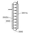
이에 대하여 금속공기전지(31)에서는 도19에 나타나 있는 바와 같이 보조 전극층(34)(의 보조 도전층(342))의 상하방향의 길이가 부극층(33)(의 부극 도전층(331))보다 짧고, 도16의 원통형의 금속공기전지(31)에서는 내측에 배치되는 부극층(33)의 외측면(330)의 면적이 외측에 배치되는 보조 전극층(34)의 내측면(340)의 면적보다 크다. 보조 전극층(34)의 내측면(340) 및 부극층(33)의 외측면(330)을 각각 보조 대향면(340) 및 부극대향(330)로 바꿔 말하면, 부극대향(330)이 보조 대향면(340)의 엣지부(도19에서는 보조 대향면(340)의 상단부(3401) 및 하단부(3402))에 대향하는 부위로부터 외측으로 넓어지는 부위(3301, 3302)를 구비한다. 이에 따라 충전시 부극층(33)의 상단부 및 하단부에 부극층(391a)과 보조 전극층(34) 사이의 전류밀도가 높아지는 것이 방지된다. 그 결과 부극층(33)의 부극대향(330) 상에 금속을 거의 균일하게 석출시킬 수 있어(금속이 국소적으로 석출되는 것이 방지되어), 부극층(33)과 보조 전극층(34)이 단락하는 것을 방지할 수 있다. On the other hand, in the metal-air battery 31, as shown in FIG. 19, the length of the up-down direction of the auxiliary electrode layer 34 (the auxiliary conductive layer 342) is negative electrode layer 33 (negative electrode conductive layer 331). Shorter, in the cylindrical metal-air battery 31 shown in FIG. 16, the area of the outer surface 330 of the negative electrode layer 33 disposed inside is the area of the inner surface 340 of the auxiliary electrode layer 34 disposed outside. Greater than In other words, the inner surface 340 of the auxiliary electrode layer 34 and the outer surface 330 of the negative electrode layer 33 are replaced with the auxiliary facing surface 340 and the negative facing 330, respectively. And a portion 3301, 3302 that extends outward from a portion facing the edge portion (340, upper end portion 3401 and lower end portion 3402 of the auxiliary opposing surface 340 in FIG. 19). Accordingly, the current density between the negative electrode layer 391a and the auxiliary electrode layer 34 is prevented from increasing at the upper and lower ends of the negative electrode layer 33 during charging. As a result, the metal can be deposited almost uniformly on the negative electrode facing 330 of the negative electrode layer 33 (preventing the metal from being deposited locally), so that the negative electrode layer 33 and the auxiliary electrode layer 34 are short-circuited. Can be prevented.

또한 부극층(33)이 다공질 부재이므로 활성인 공부(孔部)로 금속이 석출되기 쉬워져서 부극층(33) 상에 금속이 수지상으로 석출되는 것(소위 덴드라이트의 발생)을 억제할 수 있다. 또한 스테인레스강으로 형성된 보조 전극층(34)에는 탄소로 형성된 전극을 사용하여 충전시에 이산화탄소의 발생을 억제할 수 있다.In addition, since the negative electrode layer 33 is a porous member, the metal is easily precipitated by active studying, and the precipitation of the metal in the resin phase on the negative electrode layer 33 (so-called generation of dendrites) can be suppressed. . In addition, the auxiliary electrode layer 34 formed of stainless steel can be used to suppress the generation of carbon dioxide during charging by using an electrode formed of carbon.

금속공기전지(31)에서는 제1전해질층(311)에 포함된 전해액에 대하여 발액성을 가진 발액층(321)이, 정극 도전층(322) 및 정극 촉매층(323)의, 제1전해질층(311)과 반대측에 설치됨으로써, 가령 전해액이 정극 촉매층(323) 및 정극 도전층(322)을 침투(통과)한다고 하더라도 전해액이 정극 지지부(361)의 내측에(즉 공기 유입관(35)의 근방에) 누출되는 것을 방지할 수 있다. 또한 발액층(321)이 다공질 부재이므로 정극 도전층(322) 및 정극 촉매층(323)에 대한 공기의 공급을 가능하게 하면서, 전해액의 누출(누액)을 방지할 수 있다.In the metal-air battery 31, the liquid-repellent layer 321 having liquid repellency with respect to the electrolyte contained in the first electrolyte layer 311 is formed of the first electrolyte layer (the positive electrode conductive layer 322 and the positive electrode catalyst layer 323). 311), the electrolyte solution penetrates (passes) the positive electrode catalyst layer 323 and the positive electrode conductive layer 322 even inside the positive electrode support part 361 (i.e., near the air inlet pipe 35). E) can prevent leakage. In addition, since the liquid repellent layer 321 is a porous member, it is possible to supply air to the positive electrode conductive layer 322 and the positive electrode catalyst layer 323, and prevent leakage of electrolyte (leakage).

보조 전극층(34)에서는 전해액에 대한 발액성이 있고 다공질 부재인 발액층(341)이 보조 도전층(342)의, 제2전해질층(312)과 반대측 면에 설치됨으로써, 보조 도전층(342)에 공기를 공급하면서 전해액이 보조 전극층(34)의 바깥으로 누출되는 것을 방지할 수 있다.In the auxiliary electrode layer 34, the liquid-repellent layer 341, which is liquid-repellent to the electrolyte and is a porous member, is provided on the side opposite to the second electrolyte layer 312 of the auxiliary conductive layer 342, thereby providing the auxiliary conductive layer 342. It is possible to prevent the electrolyte from leaking out of the auxiliary electrode layer 34 while supplying air to the auxiliary electrode layer 34.

금속공기전지(31)의 설계에 따라서는 제1 및 제2전해질층(311, 312)의 수계 전해액에 무기 미립자(필러)가 첨가되어도 좋다. 무기 미립자로서는 알루미나나 이산화규소(SiO2), 이산화티탄(TiO2), 제올라이트, 페로브스카이트형 산화물 등의 무기 산화물이 바람직하고, 특히 Si비가 높은(예를 들면 Si/Al이 2 이상인) 제올라이트 입자가 더욱 바람직하다. 제1전해질층(311)의 전해액이 무기 미립자를 포함하므로 금속공기전지(31)의 내부저항이 감소하여 전지용량이 증대함과 더불어 금속공기전지(31)로부터의 누액이 방지된다.Depending on the design of the metal-air battery 31, inorganic fine particles (filler) may be added to the aqueous electrolyte solution of the first and second electrolyte layers 311 and 312. As the inorganic fine particles, inorganic oxides such as alumina, silicon dioxide (SiO 2 ), titanium dioxide (TiO 2 ), zeolite, and perovskite oxides are preferable, and zeolites having a high Si ratio (for example, Si / Al of 2 or more) are particularly preferred. Particles are more preferred. Since the electrolyte of the first electrolyte layer 311 contains inorganic fine particles, the internal resistance of the metal-air battery 31 decreases, thereby increasing the battery capacity and preventing leakage of the metal-air battery 31.

이상과 같이 본 발명의 제11실시형태에 대하여 설명했으나, 상기 실시형태는 다양한 변경이 가능하다. As described above, the eleventh embodiment of the present invention has been described, but the above embodiment can be modified in various ways.

제1 및 제2전해질층(311, 312)에 고체 전해질이 사용되어도 좋다. 또한 발액층은 필요에 따라 설치되는 것으로 족하고, 예를 들면 고체 전해질이 사용되는 경우에는 생략할 수 있다. 부극층(33)의 부극 도전층(331)은 방전시에 산화되어 금속이온을 생성(방출)하는 금속을 포함한 다양한 재료로 형성되어도 좋다.Solid electrolytes may be used for the first and second electrolyte layers 311 and 312. The liquid repellent layer is sufficient to be provided as necessary, and may be omitted, for example, when a solid electrolyte is used. The negative electrode conductive layer 331 of the negative electrode layer 33 may be formed of various materials including a metal which is oxidized during discharge to generate (release) metal ions.

정극층(32)에서는 정극 지지부(361) 및 발액층(321)이 도전성 재료로 형성되어 있는 경우에는, 정극 집전체(324)를 생략하고 정극 지지부(361)의 내측면에 정극 집전단자(325)를 설치하여도 좋다. 또한 정극 도전층(322)이 어느 정도의 두께로 형성되어 있을 경우에는, 정극 도전층(322)을 지지하는 정극 지지부(361)는 생략되어도 좋다. 이 경우에 정극 집전단자(325)는 정극 도전층(322)의 내측면에 설치된다.In the positive electrode layer 32, when the positive electrode support part 361 and the liquid repellent layer 321 are formed of a conductive material, the positive electrode current collector 324 is omitted and the positive electrode current collector terminal 325 is disposed on the inner side of the positive electrode support part 361. ) May be installed. In addition, when the positive electrode conductive layer 322 is formed to some extent, the positive electrode support part 361 which supports the positive electrode conductive layer 322 may be abbreviate | omitted. In this case, the positive electrode current collector terminal 325 is provided on the inner side surface of the positive electrode conductive layer 322.

금속공기전지에서는 정극 지지부(361)의 재료와 정극 도전층(322)의 재료(즉 페로브스카이트형 산화물)를 혼합한 것으로 도전층을 형성하고, 당해 도전층 상에 정극 촉매층(323)을 형성하여 정극층(32)으로 하여도 좋다. 또한 정극 지지부(361), 정극 도전층(322) 및 정극 촉매층(323)의 각 재료가 혼합된 것으로 정극층(32)이 형성되어도 좋다. 어느 경우라도 정극층(32)이 도전성을 가진 페로브스카이트형 산화물 및 산소환원반응을 촉진하는 촉매를 포함하면서 탄소를 포함하고 있지 않기 때문에, 금속공기전지의 방전시 부극층(33)에 포함된 금속의 탄산염이 정극층(32) 상에 생성되는 것을 방지할 수 있다. 금속탄산염의 생성이 문제되지 않는 경우에는 정극 도전층(322)이 다른 도전성 재료로 형성되어도 좋다.In the metal-air battery, a conductive layer is formed by mixing a material of the positive electrode support part 361 and a material of the positive electrode conductive layer 322 (that is, a perovskite oxide), and a positive electrode catalyst layer 323 is formed on the conductive layer. The positive electrode layer 32 may be used. The positive electrode layer 32 may be formed by mixing the materials of the positive electrode support part 361, the positive electrode conductive layer 322, and the positive electrode catalyst layer 323. In either case, since the positive electrode layer 32 contains a conductive perovskite oxide and a catalyst for promoting an oxygen reduction reaction and does not contain carbon, the positive electrode layer 32 is included in the negative electrode layer 33 during discharge of the metal-air battery. Metal carbonate can be prevented from being formed on the positive electrode layer 32. When generation of metal carbonate is not a problem, the positive electrode conductive layer 322 may be formed of another conductive material.

상기 금속공기전지의 구조는 예를 들면 평판형의 금속공기전지에 적용되어도 좋다. 이 경우도 부극 대향면 및 보조 대향면이 서로 대향하고, 부극 대향면이 보조 대향면의 엣지부와 대향하는 부위로부터 외측으로 넓어지는 부위(즉 서로 평행한 양면의 법선방향에서 당해 엣지부와 겹치는 부극 대향면 상의 부위로부터 당해 법선에 수직한 방향을 따라 당해 엣지부로부터 바깥으로 넓어지는 부위)를 구비함으로써, 충전시 부극층 상에 금속이 국소적으로 석출되는 것이 방지된다. 이상과 같이 부극층과 보조 전극층의 단락이 방지되는 금속공기전지는 다양한 형상으로 실현할 수 있다. 다만 정극층, 부극층 및 보조 전극층이 통상인 경우에는, 활성이면서 덴드라이트가 발생하기 쉬운 엣지부를 평판형에 비하여 줄일 수 있고(즉 엣지부가 상하단으로만 제한된다), 덴드라이트의 발생 또한 억제할 수 있다.The structure of the metal air battery may be applied to, for example, a flat metal air battery. Also in this case, the negative electrode opposing face and the auxiliary opposing face face each other, and the negative electrode opposing face extends outward from the portion facing the edge portion of the auxiliary opposing face (that is, overlapping with the edge portion in the normal direction of both sides parallel to each other). By providing a portion that widens outwardly from the edge portion along a direction perpendicular to the normal from the portion on the negative electrode facing surface, thereby preventing local precipitation of metal on the negative electrode layer during charging. As described above, the metal-air battery in which the short circuit between the negative electrode layer and the auxiliary electrode layer is prevented can be realized in various shapes. However, in the case where the positive electrode layer, the negative electrode layer, and the auxiliary electrode layer are normal, the edge portion that is active and susceptible to dendrites can be reduced as compared with the flat plate type (that is, the edge portion is limited to the upper and lower ends), and the generation of dendrites can also be suppressed. Can be.

상기 실시형태 및 각 변형예의 구성은 서로 모순되지 않는 한 적절하게 조합되어도 좋다.The configurations of the above embodiments and the respective modifications may be appropriately combined as long as they do not contradict each other.

발명을 상세하게 묘사하여 설명하였으나 상기의 설명은 예시적인 것이며 한정적인 것은 아니다. 따라서 본 발명의 범위를 일탈하지 않는 한 다수의 변형이나 태양이 가능하다고 할 수 있다.
While the invention has been described and described in detail, the foregoing description is intended to be illustrative and not restrictive. Therefore, many modifications and variations are possible without departing from the scope of the present invention.

11, 11a~11d, 21, 21a~21d, 31: 금속공기전지
12, 22, 22a: 정극
13, 23: 부극
14, 16, 24, 26, 311, 312: 전해질층
17, 17a: 분리벽층
32: 정극층
33: 부극층
34: 보조 전극층
121, 221: 정극 지지부
122, 222, 322: 정극 도전층
123, 223, 223a, 323: 정극 촉매층
229: 발액층
330: 부극 대향면
340: 보조 대향면
3301, 3302: (외측으로 확장된)부위
3401: 상단부
3402: 하단부
11, 11a-11d, 21, 21a-21d, 31: metal air battery
12, 22, 22a: positive electrode
13, 23: negative
14, 16, 24, 26, 311, and 312: electrolyte layer
17, 17a: partition wall
32: positive electrode layer
33: negative electrode layer
34: auxiliary electrode layer
121, 221: positive electrode support
122, 222, 322: positive electrode conductive layer
123, 223, 223a, and 323: positive electrode catalyst layer
229: liquid-repellent layer
330: negative opposite surface
340: secondary facing surface
3301, 3302: parts (extended)
3401: top
3402: bottom

Claims (16)

금속공기전지(金屬空氣電池)로서,
금속을 포함하면서 방전(放電)시에 금속이온(金屬 ion)을 생성하는 부극(負極)과,
도전성(導電性)을 구비하는 페로브스카이트형 산화물(perovskite type 酸化物) 및 산소환원반응(酸素還元反應)을 촉진하는 촉매를 포함하면서 탄소를 포함하지 않고, 방전시에 산소이온을 생성하는 다공질의 정극(正極)과,
상기 부극과 상기 정극 사이에 배치되는 전해질층(電解質層)을
구비하는 것을 특징으로 하는 금속공기전지.
As a metal air battery,
A negative electrode containing metal and generating metal ions during discharge;
Porous, which contains a conductive perovskite type oxide and a catalyst for promoting an oxygen reduction reaction and does not contain carbon and generates oxygen ions during discharge Positive electrode,
Electrolyte layer disposed between the negative electrode and the positive electrode
Metal air battery, characterized in that provided.
제1항에 있어서,
상기 정극이,
지지부(支持部)와,
상기 지지부 상에 상기 페로브스카이트형 산화물로 형성된 도전막(導電膜)과,
상기 도전막 상에 상기 촉매로 형성된 촉매층(觸媒層)을
구비하는 것을 특징으로 하는 금속공기전지.
The method of claim 1,
The positive electrode,
Support,
A conductive film formed of the perovskite oxide on the support portion;
A catalyst layer formed of the catalyst on the conductive film
Metal air battery, characterized in that provided.
제1항에 있어서,
상기 전해질층과 상기 정극 사이에 배치되어서 상기 정극에 접하는 또 하나의 전해질층과,
상기 전해질층과 상기 또 하나의 전해질층 사이에 배치되어서 상기 전해질층 및 상기 또 하나의 전해질층에 접하는 고체 전해질(固體電解質) 또는 세퍼레이터(separator)인 분리벽층(分離壁層)을
추가로 구비하는 것을 특징으로 하는 금속공기전지.
The method of claim 1,
Another electrolyte layer disposed between the electrolyte layer and the positive electrode and in contact with the positive electrode;
A partition wall layer disposed between the electrolyte layer and the another electrolyte layer and serving as a solid electrolyte or a separator contacting the electrolyte layer and the another electrolyte layer;
A metal air battery, characterized in that further provided.
제3항에 있어서,
상기 분리벽층이 막모양(膜模樣)의 고체 전해질이며,
상기 전해질층이, 비수계(非水系)의 전해질 용액(電解質溶液)을 함침(含浸)시킨 다공질 폴리머(多孔質 polymer)이며, 상기 분리벽층을 지지하는 것을 특징으로 하는 금속공기전지.
The method of claim 3,
The partition wall layer is a membrane-shaped solid electrolyte,
And said electrolyte layer is a porous polymer impregnated with a non-aqueous electrolyte solution, and supports said separation wall layer.
제1항에 있어서,
외주(外周)에 상기 부극이 배치되고, 내주(內周)에 상기 정극이 배치되는 원통형인 것을 특징으로 하는 금속공기전지.
The method of claim 1,
A metal air battery, wherein the negative electrode is disposed on an outer circumference and the cylindrical shape is disposed on the inner circumference.
제1항 내지 제5항 중의 어느 하나의 항에 있어서,
상기 전해질층이 전해질 용액으로 형성되어 있고,
상기 전해질 용액이 무기 미립자(無機微粒子)를 포함하는 것을 특징으로 하는 금속공기전지.
6. The method according to any one of claims 1 to 5,
The electrolyte layer is formed of an electrolyte solution,
A metal air battery, wherein the electrolyte solution contains inorganic fine particles.
제1항에 있어서,
상기 정극에 설치되고, 상기 전해질층에 포함된 전해액(電解液)에 대한 발액성(撥液性)을 가진 발액층(撥液層)을 추가로 구비하는 것을 특징으로 하는 금속공기전지.
The method of claim 1,
The metal-air battery provided in the said positive electrode and further provided with the liquid repellent layer which has liquid repellency with respect to the electrolyte solution contained in the said electrolyte layer.
제7항에 있어서,
상기 부극, 상기 정극, 상기 전해질층 및 상기 발액층이 동심(同心)의 유저 원통형(有底圓筒形)인 것을 특징으로 하는 금속공기전지.
The method of claim 7, wherein
And said negative electrode, said positive electrode, said electrolyte layer and said liquid repellent layer are concentric user cylinders.
제7항 또는 제8항에 있어서,
상기 정극이,
지지부와,
상기 지지부 상에 상기 페로브스카이트형 산화물로 형성된 도전막과,
상기 도전막 상에 상기 촉매로 형성된 촉매층을
구비하는 것을 특징으로 하는 금속공기전지.
9. The method according to claim 7 or 8,
The positive electrode,
Support,
A conductive film formed of the perovskite oxide on the support portion;
The catalyst layer formed of the catalyst on the conductive film
Metal air battery, characterized in that provided.
제9항에 있어서,
상기 발액층이, 상기 도전막 및 상기 촉매층에 대하여 상기 전해질층과는 반대측에 설치되는 다공질 부재(多孔質部材)인 것을 특징으로 하는 금속공기전지.
10. The method of claim 9,
And the liquid-repellent layer is a porous member provided on the side opposite to the electrolyte layer with respect to the conductive film and the catalyst layer.
제9항에 있어서,
상기 촉매층이 프랙탈 구조(fractal 構造)를 구비하고, 상기 도전막과 상기 전해질층 사이에 배치됨과 더불어 상기 발액층을 겸하는 것을 특징으로 하는 금속공기전지.
10. The method of claim 9,
And the catalyst layer has a fractal structure, is disposed between the conductive film and the electrolyte layer, and serves as the liquid repellent layer.
제9항에 있어서,
상기 촉매층에 있어서 상기 촉매가 다수의 섬모양(島模樣) 또는 다공질상(多孔質狀)으로 형성되고, 상기 촉매간에 상기 전해액에 대한 발액성을 가진 재료가 부여되어 있고,
상기 촉매층이 상기 도전막과 상기 전해질층 사이에 배치됨과 더불어 상기 발액층을 겸하는 것을 특징으로 하는 금속공기전지.
10. The method of claim 9,
In the catalyst layer, the catalyst is formed in a plurality of islands or porous phases, and a material having liquid repellency for the electrolyte is provided between the catalysts.
And the catalyst layer is disposed between the conductive film and the electrolyte layer, and serves as the liquid repellent layer.
금속공기전지로서,
금속을 포함하면서 방전시에 금속이온을 생성하는 부극층과,
도전성 재료 및 산소환원반응을 촉진하는 촉매를 포함하고 방전시에 산소이온을 생성하는 다공질의 정극층과,
상기 부극층과 상기 정극층 사이에 배치되는 제1전해질층과,
상기 부극층에 있어서 상기 정극층과 반대측 면에 대향하는 면을 구비하는 보조 전극층과,
상기 부극층과 상기 보조 전극층 사이에 배치되고 상기 제1전해질층과 통하는 제2전해질층을
구비하고,
상기 부극층의 상기 면이 상기 보조 전극층의 상기 면의 엣지부와 대향하는 부위보다 외측으로 확장된 부위를 구비하고,
충전시에 상기 부극층과 상기 보조 전극층 사이에 전압이 부여됨으로써 상기 부극층 상에 상기 금속이 석출(析出)되는 것을 특징으로 하는 금속공기전지.
As a metal air battery,
A negative electrode layer containing metal and generating metal ions during discharge;
A porous positive electrode layer containing a conductive material and a catalyst for promoting an oxygen reduction reaction and generating oxygen ions at discharge;
A first electrolyte layer disposed between the negative electrode layer and the positive electrode layer,
An auxiliary electrode layer having a surface opposed to the surface opposite to the positive electrode layer in the negative electrode layer;
A second electrolyte layer disposed between the negative electrode layer and the auxiliary electrode layer and communicating with the first electrolyte layer;
Respectively,
The surface of the negative electrode layer has a portion that extends outward from a portion facing the edge portion of the surface of the auxiliary electrode layer,
A metal air battery, wherein the metal is deposited on the negative electrode layer by applying a voltage between the negative electrode layer and the auxiliary electrode layer during charging.
제13항에 있어서,
상기 정극층, 상기 부극층 및 상기 보조 전극층이 통상이며, 상기 정극층이 상기 부극층의 내측에 배치되고, 상기 보조 전극층이 상기 부극층의 외측에 배치되는 것을 특징으로 하는 금속공기전지.
The method of claim 13,
The positive electrode layer, the negative electrode layer, and the auxiliary electrode layer are common, the positive electrode layer is disposed inside the negative electrode layer, and the auxiliary electrode layer is disposed outside the negative electrode layer.
제13항에 있어서,
상기 부극층이 다공질 부재인 것을 특징으로 하는 금속공기전지.
The method of claim 13,
The metal air battery, wherein the negative electrode layer is a porous member.
제13항 내지 제15항에 있어서,
상기 도전성 재료가 페로브스카이트형 산화물이며, 상기 정극층이 탄소를 포함하지 않는 것을 특징으로 하는 금속공기전지.
The method according to claim 13, wherein
And said conductive material is a perovskite oxide and said positive electrode layer does not contain carbon.
KR1020127031693A 2010-06-04 2011-06-01 Metal air battery KR20130112697A (en)

Applications Claiming Priority (7)

Application Number Priority Date Filing Date Title
JPJP-P-2010-128796 2010-06-04
JP2010128796A JP2011253789A (en) 2010-06-04 2010-06-04 Metal-air battery
JP2010249938A JP2012104273A (en) 2010-11-08 2010-11-08 Metal-air battery
JPJP-P-2010-249938 2010-11-08
JP2011071500A JP5773699B2 (en) 2011-03-29 2011-03-29 Metal air battery
JPJP-P-2011-071500 2011-03-29
PCT/JP2011/062616 WO2011152464A1 (en) 2010-06-04 2011-06-01 Metal air battery

Publications (1)

Publication Number Publication Date
KR20130112697A true KR20130112697A (en) 2013-10-14

Family

ID=45066822

Family Applications (1)

Application Number Title Priority Date Filing Date
KR1020127031693A KR20130112697A (en) 2010-06-04 2011-06-01 Metal air battery

Country Status (4)

Country Link
US (2) US20130078535A1 (en)
KR (1) KR20130112697A (en)
CN (1) CN102934280A (en)
WO (1) WO2011152464A1 (en)

Cited By (2)

* Cited by examiner, † Cited by third party
Publication number Priority date Publication date Assignee Title
WO2017135793A1 (en) * 2016-02-05 2017-08-10 주식회사 엘지화학 Cable-type secondary battery and manufacturing method therefor
KR20190055698A (en) * 2017-11-15 2019-05-23 삼성전자주식회사 Metal-air battery

Families Citing this family (22)

* Cited by examiner, † Cited by third party
Publication number Priority date Publication date Assignee Title
US9217198B2 (en) 2011-07-07 2015-12-22 Itn Energy Systems, Inc. Insertion of lithium into electrochromic devices after completion
US9293796B2 (en) 2011-12-15 2016-03-22 Itn Energy Systems, Inc. Metal-air battery with dual electrode anode
US8980485B2 (en) * 2011-12-30 2015-03-17 Itn Energy Systems, Inc. Rechargeable, thin-film, all solid-state metal-air battery
US9013777B2 (en) 2012-02-03 2015-04-21 Itn Energy Systems, Inc. Integrated device architectures for electrochromic devices
KR102032245B1 (en) * 2012-04-03 2019-10-16 삼성전자주식회사 Lithium air battery module
JP6250551B2 (en) * 2012-04-25 2017-12-20 日立造船株式会社 Method for producing functional porous body
US9899654B2 (en) 2013-03-29 2018-02-20 Hitachi Zosen Corporation Metal-air battery
US20140335429A1 (en) * 2013-05-10 2014-11-13 Zinc Air Fuel Cells, Inc. Alkaline battery with electrolyte gradient
US8728671B1 (en) * 2013-06-05 2014-05-20 ZAF Energy Systems, Incorporated Air electrodes including perovskites
US10044028B1 (en) 2014-01-29 2018-08-07 Itn Energy Systems, Inc. Composite cathode solid state battery
JP6626456B2 (en) * 2014-04-29 2019-12-25 マーレ インターナショナル ゲゼルシャフト ミット ベシュレンクテル ハフツングMAHLE International GmbH Air battery
DE102014208044A1 (en) * 2014-04-29 2015-10-29 Mahle International Gmbh Metal-air battery
JP6588716B2 (en) * 2015-03-24 2019-10-09 日立造船株式会社 Metal air battery
KR102364844B1 (en) * 2015-04-30 2022-02-18 삼성전자주식회사 Metal air battery and operation method of the metal air battery
JP2017208197A (en) * 2016-05-17 2017-11-24 日立造船株式会社 Metal air secondary battery
CN107799853A (en) * 2016-09-05 2018-03-13 中国科学院宁波材料技术与工程研究所 A kind of high-temperature solid lithium metal oxidate for lithium lithium-ion energy storage battery
US11476522B2 (en) * 2017-11-15 2022-10-18 Samsung Electronics Co., Ltd. Metal-air battery
CN109638309B (en) * 2018-12-14 2022-03-29 北京工业大学 Gas-phase countercurrent diaphragm-free metal-oxygen-containing gas flow battery
US20210226224A1 (en) * 2020-01-21 2021-07-22 Samsung Electronics Co., Ltd. Cathode including base-resistant compound and lithium-air battery including the same
JP2023007594A (en) * 2021-07-02 2023-01-19 三菱重工業株式会社 metal air battery system
CN113644347B (en) * 2021-09-02 2022-11-11 烟台浩忆生物科技有限公司 Metal-air battery and liquid injection method thereof
CN114843528B (en) * 2022-06-02 2024-01-26 何金立 Depolarization method of metal fuel cell, three-electrode metal fuel cell and application

Family Cites Families (26)

* Cited by examiner, † Cited by third party
Publication number Priority date Publication date Assignee Title
GB1284738A (en) * 1967-11-03 1972-08-09 Shell Int Research Metal-air cells
JPS4947851A (en) * 1972-09-14 1974-05-09
US3881959A (en) * 1972-09-14 1975-05-06 Fuji Electrochemical Co Ltd Air cell
JPS50121746A (en) * 1974-02-22 1975-09-23
JPS5692365U (en) * 1979-12-18 1981-07-23
JPS5844670A (en) * 1981-09-08 1983-03-15 Toshiba Battery Co Ltd Manufacture of air cell
JPH0417259A (en) * 1990-05-10 1992-01-22 Matsushita Electric Ind Co Ltd Battery
US5270128A (en) * 1992-04-03 1993-12-14 Eveready Battery Company, Inc. Air assisted alkaline cell
JP3382646B2 (en) * 1992-10-09 2003-03-04 日立マクセル株式会社 Oxygen catalyst electrode and air battery using it
US5401372A (en) * 1993-04-26 1995-03-28 Ceramatec, Inc. Electrochemical catalytic reduction cell for the reduction of NOx in an O2 -containing exhaust emission
JP2653415B2 (en) * 1994-04-06 1997-09-17 工業技術院長 Battery provided with gas diffusion electrode and method for charging and discharging the same
JPH0950828A (en) * 1995-08-04 1997-02-18 Matsushita Electric Ind Co Ltd Rectangular air cell
AU775596B2 (en) * 2000-07-19 2004-08-05 Johns Hopkins University, The Scalable, all-polymer fuel cell
JP2003109606A (en) * 2001-09-28 2003-04-11 Matsushita Electric Ind Co Ltd High molecular electrolyte fuel cell and method of manufacturing the same
US7087348B2 (en) * 2002-07-26 2006-08-08 A123 Systems, Inc. Coated electrode particles for composite electrodes and electrochemical cells
US20040241537A1 (en) * 2003-03-28 2004-12-02 Tetsuo Okuyama Air battery
US7282295B2 (en) * 2004-02-06 2007-10-16 Polyplus Battery Company Protected active metal electrode and battery cell structures with non-aqueous interlayer architecture
US20060088768A1 (en) * 2004-10-25 2006-04-27 Fang Jang C Electrode structure of lithium battery
US7291186B2 (en) * 2004-11-01 2007-11-06 Teck Cominco Metals Ltd. Solid porous zinc electrodes and methods of making same
JP2006147442A (en) * 2004-11-24 2006-06-08 Matsushita Electric Ind Co Ltd Aluminum air cell
US20070141440A1 (en) * 2005-12-21 2007-06-21 General Electric Company Cylindrical structure fuel cell
JP2008066202A (en) * 2006-09-08 2008-03-21 National Institute Of Advanced Industrial & Technology Air battery
EP2087540A4 (en) * 2006-10-13 2014-01-22 Ceramatec Inc Advanced metal-air battery having a ceramic membrane electrolyte
JP2009230981A (en) * 2008-03-21 2009-10-08 Toyota Central R&D Labs Inc Nonaqueous metal air battery
JP5215146B2 (en) * 2008-12-03 2013-06-19 日本電信電話株式会社 Lithium air secondary battery and method for producing lithium air secondary battery
JP5376586B2 (en) * 2009-06-29 2013-12-25 シャープ株式会社 Metal-air battery module and metal-air battery stack

Cited By (3)

* Cited by examiner, † Cited by third party
Publication number Priority date Publication date Assignee Title
WO2017135793A1 (en) * 2016-02-05 2017-08-10 주식회사 엘지화학 Cable-type secondary battery and manufacturing method therefor
US10923772B2 (en) 2016-02-05 2021-02-16 Lg Chem, Ltd. Cable-type secondary battery and method for manufacturing the same
KR20190055698A (en) * 2017-11-15 2019-05-23 삼성전자주식회사 Metal-air battery

Also Published As

Publication number Publication date
CN102934280A (en) 2013-02-13
US20130295472A1 (en) 2013-11-07
US20130078535A1 (en) 2013-03-28
WO2011152464A1 (en) 2011-12-08

Similar Documents

Publication Publication Date Title
KR20130112697A (en) Metal air battery
JP2011253789A (en) Metal-air battery
US8722278B2 (en) Solid oxide fuel cell and fuel cell module comprising the solid oxide fuel cell
JP5773699B2 (en) Metal air battery
US20110269047A1 (en) Metal-supported, segmented-in-series high temperature electrochemical device
KR101488915B1 (en) Iron-air accumulator with lithium mediator
EP3084870A1 (en) Electrochemical energy conversion devices and cells, and positive electrode-side materials for them
JP5904854B2 (en) Metal air battery
EP3046171B1 (en) Fuel cell and fuel cell stack
JP2013140696A (en) Solid oxide fuel battery cell
CN102651480A (en) Anode-supported solid oxide fuel cell, cell stack and preparation method thereof
JP2012104273A (en) Metal-air battery
JP5413808B2 (en) Solid oxide fuel cell and fuel cell module including the same
JP2010016000A (en) Solid electrolyte fuel battery cell stack, bundle, fuel cell, and manufacturing method of fuel cell stack
US20090130523A1 (en) Tubular Solid Polymer Fuel Cell Comprising a Rod-Shaped Current Collector With Peripheral Glas Flow Channels and Production Method Thereof
KR101015698B1 (en) Powdered fuel cell
JP5199218B2 (en) Solid oxide fuel cell and manufacturing method thereof
CN102770998A (en) Method and system for purification of gas streams for solid oxide cells
KR101289171B1 (en) Planar Solid Oxide Fuel Cell Without Manifold Sealing
KR101188997B1 (en) Solid oxide fuel cell
KR20110022911A (en) Flat tube type solid oxide fuel cell module
US7906246B2 (en) Powdered fuel cell
KR101606161B1 (en) Manufacturing method of a tubular metal supported solid oxide fuel cell
CN218039321U (en) Supporting type solid oxide single cell, battery and energy conversion device
JP2010015807A (en) Solid oxide fuel cell, solid oxide fuel cell unit, and fuel cell module equipped with the same

Legal Events

Date Code Title Description
WITN Application deemed withdrawn, e.g. because no request for examination was filed or no examination fee was paid