JP5773699B2 - Metal air battery - Google Patents

Metal air battery Download PDF

Info

Publication number
JP5773699B2
JP5773699B2 JP2011071500A JP2011071500A JP5773699B2 JP 5773699 B2 JP5773699 B2 JP 5773699B2 JP 2011071500 A JP2011071500 A JP 2011071500A JP 2011071500 A JP2011071500 A JP 2011071500A JP 5773699 B2 JP5773699 B2 JP 5773699B2
Authority
JP
Japan
Prior art keywords
electrode layer
layer
negative electrode
metal
positive electrode
Prior art date
Legal status (The legal status is an assumption and is not a legal conclusion. Google has not performed a legal analysis and makes no representation as to the accuracy of the status listed.)
Expired - Fee Related
Application number
JP2011071500A
Other languages
Japanese (ja)
Other versions
JP2012209020A (en
JP2012209020A5 (en
Inventor
正信 相澤
正信 相澤
Current Assignee (The listed assignees may be inaccurate. Google has not performed a legal analysis and makes no representation or warranty as to the accuracy of the list.)
Kanadevia Corp
Original Assignee
Hitachi Zosen Corp
Priority date (The priority date is an assumption and is not a legal conclusion. Google has not performed a legal analysis and makes no representation as to the accuracy of the date listed.)
Filing date
Publication date
Priority to JP2011071500A priority Critical patent/JP5773699B2/en
Application filed by Hitachi Zosen Corp filed Critical Hitachi Zosen Corp
Priority to US13/700,253 priority patent/US20130078535A1/en
Priority to CN2011800274665A priority patent/CN102934280A/en
Priority to PCT/JP2011/062616 priority patent/WO2011152464A1/en
Priority to KR1020127031693A priority patent/KR20130112697A/en
Publication of JP2012209020A publication Critical patent/JP2012209020A/en
Priority to US13/934,510 priority patent/US20130295472A1/en
Publication of JP2012209020A5 publication Critical patent/JP2012209020A5/ja
Application granted granted Critical
Publication of JP5773699B2 publication Critical patent/JP5773699B2/en
Expired - Fee Related legal-status Critical Current
Anticipated expiration legal-status Critical

Links

Images

Classifications

    • YGENERAL TAGGING OF NEW TECHNOLOGICAL DEVELOPMENTS; GENERAL TAGGING OF CROSS-SECTIONAL TECHNOLOGIES SPANNING OVER SEVERAL SECTIONS OF THE IPC; TECHNICAL SUBJECTS COVERED BY FORMER USPC CROSS-REFERENCE ART COLLECTIONS [XRACs] AND DIGESTS
    • Y02TECHNOLOGIES OR APPLICATIONS FOR MITIGATION OR ADAPTATION AGAINST CLIMATE CHANGE
    • Y02EREDUCTION OF GREENHOUSE GAS [GHG] EMISSIONS, RELATED TO ENERGY GENERATION, TRANSMISSION OR DISTRIBUTION
    • Y02E60/00Enabling technologies; Technologies with a potential or indirect contribution to GHG emissions mitigation
    • Y02E60/10Energy storage using batteries

Landscapes

  • Hybrid Cells (AREA)

Description

本発明は、金属空気電池に関する。   The present invention relates to a metal-air battery.

従来より、金属を負極層の活物質とし、空気中の酸素を正極層の活物質とする金属空気電池が知られている。金属空気電池では、充電時において負極層上に金属が局所的に析出することにより正極層と負極層とが短絡する虞がある。そこで、正極層と負極層との間にセパレータを設けることにより、正極層と負極層との短絡を防止する手法が提案されている(例えば、特許文献1および2参照)。   Conventionally, a metal-air battery using a metal as an active material for a negative electrode layer and oxygen in the air as an active material for a positive electrode layer is known. In the metal-air battery, there is a possibility that the positive electrode layer and the negative electrode layer are short-circuited due to local deposition of metal on the negative electrode layer during charging. Thus, a method has been proposed in which a separator is provided between the positive electrode layer and the negative electrode layer to prevent a short circuit between the positive electrode layer and the negative electrode layer (see, for example, Patent Documents 1 and 2).

特開2008−66202号公報JP 2008-66202 A 特開2009−230981号公報JP 2009-230981 A

ところで、金属空気電池において充電用の補助電極層(すなわち、第3電極)を設け、放電時に正極層および負極層を利用し、充電時に負極層および補助電極層を利用することにより、金属空気電池の充電および放電の性能を向上することが考えられる。しかしながら、このような金属空気電池においても、充電時において負極層上に金属が局所的に析出すると、負極層と補助電極層とが短絡する虞がある。   By the way, by providing an auxiliary electrode layer (that is, a third electrode) for charging in the metal-air battery, using the positive electrode layer and the negative electrode layer during discharging, and using the negative electrode layer and the auxiliary electrode layer during charging, the metal-air battery It is conceivable to improve the charging and discharging performance. However, even in such a metal-air battery, when metal is locally deposited on the negative electrode layer during charging, the negative electrode layer and the auxiliary electrode layer may be short-circuited.

本発明は上記課題に鑑みなされたものであり、負極層と補助電極層とが短絡することを防止することを目的としている。   This invention is made | formed in view of the said subject, and aims at preventing that a negative electrode layer and an auxiliary electrode layer short-circuit.

請求項1に記載の発明は、金属空気電池であって、金属を含む負極層と、導電性材料、および、酸素還元反応を促進する触媒を含む多孔質の正極層と、前記負極層と前記正極層との間に配置される第1電解質層と、前記負極層の前記正極層とは反対側の面に対向する面を有する補助電極層と、前記負極層と前記補助電極層との間に配置され、前記第1電解質層と連通する第2電解質層とを備え、前記正極層、前記負極層および前記補助電極層が筒状であり、前記負極層の前記面が、前記補助電極層の前記面のエッジ部に対向する部位から外側に広がる部位を有し、充電の際に前記負極層と前記補助電極層との間にて電圧が付与されることにより前記負極層上に前記金属が析出する。 The invention according to claim 1 is a metal-air battery, comprising a metal-containing negative electrode layer, a conductive material, and a porous positive electrode layer containing a catalyst that promotes an oxygen reduction reaction, the negative electrode layer, and the A first electrolyte layer disposed between the positive electrode layer, an auxiliary electrode layer having a surface facing the surface of the negative electrode layer opposite to the positive electrode layer, and between the negative electrode layer and the auxiliary electrode layer And the second electrolyte layer communicating with the first electrolyte layer, the positive electrode layer, the negative electrode layer, and the auxiliary electrode layer are cylindrical, and the surface of the negative electrode layer is the auxiliary electrode layer A portion that spreads outward from a portion that faces the edge portion of the surface, and a voltage is applied between the negative electrode layer and the auxiliary electrode layer during charging so that the metal is formed on the negative electrode layer. Precipitates.

請求項2に記載の発明は、請求項1に記載の金属空気電池であって、前記正極層が前記負極層の内側に配置され、前記補助電極層が前記負極層の外側に配置される。 According to a second aspect of the invention, a metal-air battery according to claim 1, which before Symbol positive electrode layer is disposed inside the negative electrode layer, the auxiliary electrode layer is disposed on the outside of the negative electrode layer .

請求項3に記載の発明は、金属空気電池であって、多孔質部材であり、金属を含む負極層と、導電性材料、および、酸素還元反応を促進する触媒を含む多孔質の正極層と、前記負極層と前記正極層との間に配置される第1電解質層と、前記負極層の前記正極層とは反対側の面に対向する面を有する補助電極層と、前記負極層と前記補助電極層との間に配置され、前記第1電解質層と連通する第2電解質層とを備え、前記負極層の前記面が、前記補助電極層の前記面のエッジ部に対向する部位から外側に広がる部位を有し、充電の際に前記負極層と前記補助電極層との間にて電圧が付与されることにより前記負極層上に前記金属が析出する。 The invention according to claim 3, a metallic air battery, Ri multi porosifying member der, a negative electrode layer containing a metal, conductive material, and, a porous comprising a catalyst that promotes oxygen reduction reaction A positive electrode layer; a first electrolyte layer disposed between the negative electrode layer and the positive electrode layer; an auxiliary electrode layer having a surface facing the surface of the negative electrode layer opposite to the positive electrode layer; and the negative electrode A second electrolyte layer disposed between the layer and the auxiliary electrode layer and communicating with the first electrolyte layer, wherein the surface of the negative electrode layer faces an edge portion of the surface of the auxiliary electrode layer has a region extending from the site to the outside, it said metal deposited on the negative electrode layer when a voltage is applied in between the anode layer and the auxiliary electrode layer during charging.

請求項4に記載の発明は、請求項1ないし3のいずれかに記載の金属空気電池であって、前記導電性材料がペロブスカイト型酸化物であり、前記正極層が炭素を含まない。   The invention according to claim 4 is the metal-air battery according to any one of claims 1 to 3, wherein the conductive material is a perovskite oxide and the positive electrode layer does not contain carbon.

本発明によれば、負極層と補助電極層とが短絡することを防止することができる。   According to the present invention, it is possible to prevent a short circuit between the negative electrode layer and the auxiliary electrode layer.

金属空気電池を示す縦断面図である。It is a longitudinal cross-sectional view which shows a metal air battery. 金属空気電池を示す横断面図である。It is a cross-sectional view showing a metal-air battery. 比較例の金属空気電池における負極層および補助電極層を示す図である。It is a figure which shows the negative electrode layer and auxiliary electrode layer in the metal air battery of a comparative example. 他の比較例の金属空気電池における負極層および補助電極層を示す図である。It is a figure which shows the negative electrode layer and auxiliary electrode layer in the metal air battery of another comparative example. 負極層および補助電極層を示す図である。It is a figure which shows a negative electrode layer and an auxiliary electrode layer.

図1は、本発明の一の実施の形態に係る金属空気電池1を示す縦断面図である。金属空気電池1は略円筒状であり、図1は、金属空気電池1の中心軸J1を含む断面を示す。図2は、金属空気電池1を図1中のA−Aの位置にて切断した横断面図である。図1および図2に示すように、金属空気電池1は、正極層2、負極層3および電解質層11を備える二次電池である。金属空気電池1は、空気導入管5、もう1つの電解質層12および補助電極層4をさらに備え、中心軸J1から径方向の外側に向かって、空気導入管5、正極層2、電解質層11、負極層3、電解質層12および補助電極層4が、順に同心円状に配置される。以下の説明では、正極層2と負極層3との間の電解質層11を第1電解質層11と呼び、負極層3と補助電極層4との間の電解質層12を第2電解質層12と呼ぶ。   FIG. 1 is a longitudinal sectional view showing a metal-air battery 1 according to an embodiment of the present invention. The metal-air battery 1 has a substantially cylindrical shape, and FIG. 1 shows a cross section including the central axis J1 of the metal-air battery 1. FIG. 2 is a cross-sectional view of the metal-air battery 1 cut at the position AA in FIG. As shown in FIGS. 1 and 2, the metal-air battery 1 is a secondary battery including a positive electrode layer 2, a negative electrode layer 3, and an electrolyte layer 11. The metal-air battery 1 further includes an air introduction tube 5, another electrolyte layer 12, and an auxiliary electrode layer 4, and the air introduction tube 5, the positive electrode layer 2, and the electrolyte layer 11 from the central axis J <b> 1 outward in the radial direction. The negative electrode layer 3, the electrolyte layer 12, and the auxiliary electrode layer 4 are arranged concentrically in order. In the following description, the electrolyte layer 11 between the positive electrode layer 2 and the negative electrode layer 3 is referred to as a first electrolyte layer 11, and the electrolyte layer 12 between the negative electrode layer 3 and the auxiliary electrode layer 4 is referred to as a second electrolyte layer 12. Call.

正極層2は、略有底円筒状の多孔質部材であり、それぞれが略有底円筒状の正極導電層22および正極触媒層23、並びに、後述の電解液に対する撥液性(本実施の形態では、水系の電解液に対する撥水性)を有する多孔質の撥液層21を備える。詳細には、金属空気電池1では、中心軸J1を中心とする略有底円筒状の正極支持部61が設けられ、撥液層21は正極支持部61の外側面上および外底面上に積層される。また、正極導電層22は撥液層21の外側面上および外底面上に積層され、正極触媒層23は正極導電層22の外側面上および外底面上に積層される。正極層2では、正極導電層22の外側面の一部において、正極触媒層23に代えて正極集電体24が設けられ、図1に示すように、正極集電体24の上端に正極集電端子25が接続される。好ましくは、正極層2(すなわち、撥液層21、正極導電層22、正極触媒層23および正極集電体24)には炭素(C)は含まれない。   The positive electrode layer 2 is a substantially bottomed cylindrical porous member, each of which has a substantially bottomed cylindrical positive electrode conductive layer 22 and a positive electrode catalyst layer 23, and a liquid repellency with respect to an electrolyte described later (this embodiment) Then, a porous liquid repellent layer 21 having water repellency with respect to an aqueous electrolyte is provided. Specifically, in the metal-air battery 1, a substantially bottomed cylindrical positive electrode support portion 61 centering on the central axis J1 is provided, and the liquid repellent layer 21 is laminated on the outer surface and the outer bottom surface of the positive electrode support portion 61. Is done. The positive electrode conductive layer 22 is laminated on the outer side surface and the outer bottom surface of the liquid repellent layer 21, and the positive electrode catalyst layer 23 is laminated on the outer side surface and the outer bottom surface of the positive electrode conductive layer 22. In the positive electrode layer 2, a positive electrode current collector 24 is provided on a part of the outer surface of the positive electrode conductive layer 22 instead of the positive electrode catalyst layer 23, and the positive electrode current collector 24 is disposed at the upper end of the positive electrode current collector 24 as shown in FIG. The electric terminal 25 is connected. Preferably, the positive electrode layer 2 (that is, the liquid repellent layer 21, the positive electrode conductive layer 22, the positive electrode catalyst layer 23, and the positive electrode current collector 24) does not contain carbon (C).

正極支持部61は、例えばアルミナ(酸化アルミニウム:Al)やジルコニア等のセラミック、あるいは、ステンレス鋼等の金属により形成される多孔質部材であり、本実施の形態では、正極支持部61は絶縁体であるアルミナにより形成される。正極支持部61の形成は、押し出し成形、CIP(Cold Isostatic Press:冷間等方圧プレス)および焼成、または、HIP(Hot Isostatic Press:熱間等方圧プレス)等により行われる。 The positive electrode support 61 is a porous member formed of a ceramic such as alumina (aluminum oxide: Al 2 O 3 ) or zirconia, or a metal such as stainless steel. In this embodiment, the positive electrode support 61 Is formed of alumina as an insulator. The positive electrode support 61 is formed by extrusion molding, CIP (Cold Isostatic Press) and firing, or HIP (Hot Isostatic Press).

正極導電層22は、導電性を有するペロブスカイト型酸化物(通常は粉体状)により主に形成される多孔質の薄い導電膜であり、好ましくは、化学式A1−xBO(0.9≦1−x<1.0)にて表されるペロブスカイト型酸化物により形成される。本実施の形態では、正極導電層22はランタン系のペロブスカイト型酸化物(具体的には、ランタンストロンチウムマンガナイト(LSM:La(Sr)MnO)やランタンストロンチウムコバルタイト(LSC:La(Sr)CoO)等のAサイトにランタンを含むペロブスカイト型酸化物)により形成される。正極導電層22の形成は、スラリーコート法、水熱合成法、CVD(Chemical Vapor Deposition:化学蒸着)またはPVD(Physical Vapor Deposition:物理蒸着)等により行われる。 The positive electrode conductive layer 22 is a porous thin conductive film mainly formed of a conductive perovskite oxide (usually in powder form), and preferably has a chemical formula A 1-x BO 3 (0.9 It is formed of a perovskite oxide represented by ≦ 1-x <1.0). In the present embodiment, the positive electrode conductive layer 22 includes a lanthanum perovskite oxide (specifically, lanthanum strontium manganite (LSM: La (Sr) MnO 3 ) or lanthanum strontium cobaltite (LSC: La (Sr) A perovskite oxide containing lanthanum at the A site such as CoO 3 ). The positive electrode conductive layer 22 is formed by a slurry coating method, a hydrothermal synthesis method, CVD (Chemical Vapor Deposition), PVD (Physical Vapor Deposition), or the like.

正極触媒層23は、酸素還元反応を促進する触媒であるマンガン(Mn)やニッケル(Ni)、コバルト(Co)等の金属酸化物により主に形成される多孔質部材である。正極触媒層23は、白金(Pt)やパラジウム(Pd)、銀(Ag)、ロジウム(Rh)、ルテニウム(Ru)のような貴金属、または、これらの貴金属と上記金属酸化物との混合物により形成されてもよい。本実施の形態では、正極触媒層23はβ型(ルチル型)の結晶構造を有する二酸化マンガン(MnO)により形成される。正極触媒層23の形成は、スラリーコート法および焼成、水熱合成法、CVDまたはPVD等により行われる。 The positive electrode catalyst layer 23 is a porous member mainly formed of a metal oxide such as manganese (Mn), nickel (Ni), or cobalt (Co) that is a catalyst for promoting an oxygen reduction reaction. The positive electrode catalyst layer 23 is formed of a noble metal such as platinum (Pt), palladium (Pd), silver (Ag), rhodium (Rh), ruthenium (Ru), or a mixture of these noble metals and the above metal oxide. May be. In the present embodiment, the positive electrode catalyst layer 23 is formed of manganese dioxide (MnO 2 ) having a β-type (rutile-type) crystal structure. The positive electrode catalyst layer 23 is formed by a slurry coating method and baking, a hydrothermal synthesis method, CVD, PVD, or the like.

また、正極支持部61と正極導電層22との間に配置される撥液層21は、撥水性を有する材料にて形成され、正極導電層22の形成時に高温となる場合には、高い耐熱性を有するセラミック系材料(例えば、酸化物セラミック)が用いられる。本実施の形態では、シリカ(二酸化ケイ素:SiO)やシリカ複合材料にて形成される多孔質膜が撥液層21として用いられる。金属空気電池1の設計によっては、撥水性を有していない多孔質部材に、飽和フルオロアルキル基(特に、トリフルオロメチル基(CF ))、アルキルシリル基、フルオロシリル基、長鎖アルキル基等の官能基を有する物質を被覆することにより、撥液層21が形成されてもよい。 Further, the liquid repellent layer 21 disposed between the positive electrode support 61 and the positive electrode conductive layer 22 is formed of a material having water repellency, and has a high heat resistance when the temperature is high when the positive electrode conductive layer 22 is formed. A ceramic material having a property (for example, oxide ceramic) is used. In the present embodiment, a porous film formed of silica (silicon dioxide: SiO 2 ) or a silica composite material is used as the liquid repellent layer 21. Depending on the design of the metal-air battery 1, a porous member that does not have water repellency may have a saturated fluoroalkyl group (particularly, a trifluoromethyl group (CF 3 )), an alkylsilyl group, a fluorosilyl group, or a long-chain alkyl group. The liquid repellent layer 21 may be formed by coating a substance having a functional group such as a group.

図1および図2に示すように、負極層3は、円筒状の正極層2の外側に配置される円筒状の負極導電層31を備え、負極導電層31の上側端部には、図1に示すように負極集電端子32が設けられる。負極導電層31は、亜鉛(Zn)やリチウム(Li)等の金属、または、当該金属を含む合金により形成された多孔質部材であり、本実施の形態では、負極導電層31は亜鉛または亜鉛合金により形成される。   As shown in FIGS. 1 and 2, the negative electrode layer 3 includes a cylindrical negative electrode conductive layer 31 disposed outside the cylindrical positive electrode layer 2. The negative electrode current collection terminal 32 is provided as shown in FIG. The negative electrode conductive layer 31 is a porous member formed of a metal such as zinc (Zn) or lithium (Li), or an alloy containing the metal. In the present embodiment, the negative electrode conductive layer 31 is zinc or zinc. It is formed from an alloy.

充電用の第3の電極である補助電極層4は、円筒状の負極層3の外側に配置される円筒状の補助導電層42を備える。補助導電層42は、金属等の導電性材料(本実施の形態では、ステンレス鋼)により形成される多孔質部材である。また、図1に示すように、金属空気電池1には、絶縁性材料にて形成される補助電極支持部71が設けられる。補助電極支持部71は、円筒状の上側支持部711および有底円筒状の下側支持部712を有し、補助導電層42、上側支持部711および下側支持部712の直径は同じである。補助導電層42の上端部は上側支持部711に固定され、下端部は下側支持部712に固定される。金属空気電池1では、補助導電層42および補助電極支持部71により、正極層2、負極層3、第1電解質層11および第2電解質層12を内部に収容する有底円筒状の容器が形成される。なお、図1の上下方向(中心軸J1方向)は重力方向であるとは限らない。   The auxiliary electrode layer 4 that is the third electrode for charging includes a cylindrical auxiliary conductive layer 42 disposed outside the cylindrical negative electrode layer 3. The auxiliary conductive layer 42 is a porous member formed of a conductive material such as metal (in this embodiment, stainless steel). As shown in FIG. 1, the metal-air battery 1 is provided with an auxiliary electrode support portion 71 formed of an insulating material. The auxiliary electrode support portion 71 includes a cylindrical upper support portion 711 and a bottomed cylindrical lower support portion 712, and the auxiliary conductive layer 42, the upper support portion 711, and the lower support portion 712 have the same diameter. . The upper end portion of the auxiliary conductive layer 42 is fixed to the upper support portion 711, and the lower end portion is fixed to the lower support portion 712. In the metal-air battery 1, the auxiliary conductive layer 42 and the auxiliary electrode support portion 71 form a bottomed cylindrical container that accommodates the positive electrode layer 2, the negative electrode layer 3, the first electrolyte layer 11, and the second electrolyte layer 12. Is done. In addition, the up-down direction (center axis J1 direction) of FIG. 1 is not necessarily a gravity direction.

補助導電層42の内側面40は負極導電層31の正極層2とは反対側の外側面30に対して均一な間隔で配置される。すなわち、補助導電層42の内側面40上の各位置から負極導電層31の外側面30までの距離(最短距離)が、当該内側面40の全体に亘っておよそ等しい。また、補助導電層42の外側面には、補助電極集電端子43が接続されるとともに、外側面の全体に亘って撥液層21と同様の撥液層41が形成される。   The inner side surface 40 of the auxiliary conductive layer 42 is disposed at a uniform interval with respect to the outer side surface 30 of the negative electrode conductive layer 31 opposite to the positive electrode layer 2. That is, the distance (shortest distance) from each position on the inner side surface 40 of the auxiliary conductive layer 42 to the outer side surface 30 of the negative electrode conductive layer 31 is approximately equal over the entire inner side surface 40. An auxiliary electrode current collecting terminal 43 is connected to the outer surface of the auxiliary conductive layer 42, and a liquid repellent layer 41 similar to the liquid repellent layer 21 is formed over the entire outer surface.

第1電解質層11は、水系の電解質により形成され、本実施の形態では、水酸化カリウム(KOH)を含む電解液(例えば、水1リットル当たりにKOHを8モル溶解させた8M−KOH水溶液である。電解液は電解質溶液とも呼ばれる。)が正極層2と負極層3との間に充填される(配置される)ことにより形成される。第1電解質層11は、正極層2の正極触媒層23、正極集電体24、および、負極層3の負極導電層31に接する。図1に示すように、第1電解質層11の上面は、正極支持部61の外側面および補助電極支持部71の内側面に接する略円環状の中蓋51により閉塞され、中蓋51の上方には、中蓋51と同形状の上蓋52が設けられて中蓋51の上方の開口が閉塞される。なお、第1電解質層11に含まれる電解液は、他の水系電解液や、非水系(例えば、有機溶剤系)電解液であってもよい。   The first electrolyte layer 11 is formed of an aqueous electrolyte. In the present embodiment, the first electrolyte layer 11 is an electrolytic solution containing potassium hydroxide (KOH) (for example, an 8M-KOH aqueous solution in which 8 mol of KOH is dissolved per liter of water). The electrolytic solution is also called an electrolytic solution.) Is filled (arranged) between the positive electrode layer 2 and the negative electrode layer 3. The first electrolyte layer 11 is in contact with the positive electrode catalyst layer 23 of the positive electrode layer 2, the positive electrode current collector 24, and the negative electrode conductive layer 31 of the negative electrode layer 3. As shown in FIG. 1, the upper surface of the first electrolyte layer 11 is closed by a substantially annular inner lid 51 in contact with the outer side surface of the positive electrode support portion 61 and the inner side surface of the auxiliary electrode support portion 71. The upper lid 52 having the same shape as the inner lid 51 is provided to close the opening above the inner lid 51. Note that the electrolytic solution contained in the first electrolyte layer 11 may be another aqueous electrolytic solution or a non-aqueous (for example, organic solvent based) electrolytic solution.

負極層3と補助電極層4との間の第2電解質層12は、セラミックや無機材料または有機材料等により形成された多孔質部材121を有し、多孔質部材121は押し出し成形、CIPおよび焼成、または、HIP等の方法で成形される。図1に示すように、負極導電層31の下端部と下側支持部712との間の間隙を介して、第2電解質層12と第1電解質層11とは連通し、多孔質部材121の孔内に第1電解質層11の水系の電解液が含浸する。すなわち、第2電解質層12においても電解液が充填される。   The second electrolyte layer 12 between the negative electrode layer 3 and the auxiliary electrode layer 4 has a porous member 121 formed of ceramic, an inorganic material, an organic material, or the like. The porous member 121 is formed by extrusion molding, CIP, and firing. Or by a method such as HIP. As shown in FIG. 1, the second electrolyte layer 12 and the first electrolyte layer 11 communicate with each other through the gap between the lower end portion of the negative electrode conductive layer 31 and the lower support portion 712, and the porous member 121 The aqueous electrolyte solution of the first electrolyte layer 11 is impregnated in the hole. That is, the electrolyte solution is filled also in the second electrolyte layer 12.

空気導入管5は、略有底円筒状の正極支持部61の内側に配置され、空気導入管5の下端は正極支持部61の底部近傍に位置する。空気導入管5の上端は、空気から水分および二酸化炭素を除去する除去部53に接続される。除去部53では、膜分離法または吸着により空気中の水分および二酸化炭素の除去が行われる。除去部53からの空気(すなわち、水分および二酸化炭素が除去された空気)は、空気導入管5により正極支持部61の内側において底部近傍へと導かれ、多孔質部材である正極支持部61の側部を介して正極層2へと供給されつつ正極支持部61の内側面に沿って上昇して正極支持部61の上部開口から外部へと排出される。金属空気電池1では、空気導入管5が、除去部53からの空気を正極層2に供給するガス供給部となる。正極層2に供給された空気は、多孔質部材である撥液層21および正極導電層22を通過して正極触媒層23へと供給される。金属空気電池1では、原則として、多孔質の正極触媒層23において空気と電解液との界面が形成される。   The air introduction tube 5 is disposed inside the substantially bottomed cylindrical positive electrode support portion 61, and the lower end of the air introduction tube 5 is positioned near the bottom portion of the positive electrode support portion 61. The upper end of the air introduction pipe 5 is connected to a removal unit 53 that removes moisture and carbon dioxide from the air. The removing unit 53 removes moisture and carbon dioxide in the air by membrane separation or adsorption. Air from the removal unit 53 (that is, air from which moisture and carbon dioxide have been removed) is guided to the vicinity of the bottom inside the positive electrode support 61 by the air introduction tube 5, and the positive electrode support 61 is a porous member. While being supplied to the positive electrode layer 2 through the side portion, the positive electrode support portion 61 rises along the inner surface and is discharged from the upper opening of the positive electrode support portion 61 to the outside. In the metal-air battery 1, the air introduction tube 5 serves as a gas supply unit that supplies the air from the removal unit 53 to the positive electrode layer 2. The air supplied to the positive electrode layer 2 passes through the liquid repellent layer 21 and the positive electrode conductive layer 22 which are porous members, and is supplied to the positive electrode catalyst layer 23. In the metal-air battery 1, in principle, an interface between air and an electrolytic solution is formed in the porous positive electrode catalyst layer 23.

図1および図2の金属空気電池1では、例えば、正極層2の外側面の直径が16mm(ミリメートル)であり、負極層3の内側面の直径が20mmであり、負極層3の外側面30の直径が24mmであり、補助電極層4の内側面40の直径が28mmである。なお、正極層2と負極層3との間隔(第1電解質層11の厚さ)、および、負極層3と補助電極層4との間隔(第2電解質層12の厚さ)は、4mm以下(1mm以上)であることが好ましい。   In the metal-air battery 1 of FIGS. 1 and 2, for example, the diameter of the outer surface of the positive electrode layer 2 is 16 mm (millimeters), the diameter of the inner surface of the negative electrode layer 3 is 20 mm, and the outer surface 30 of the negative electrode layer 3. The diameter of the inner surface 40 of the auxiliary electrode layer 4 is 28 mm. The distance between the positive electrode layer 2 and the negative electrode layer 3 (thickness of the first electrolyte layer 11) and the distance between the negative electrode layer 3 and the auxiliary electrode layer 4 (thickness of the second electrolyte layer 12) are 4 mm or less. (1 mm or more) is preferable.

図1の金属空気電池1において放電が行われる際には、負極集電端子32と正極集電端子25とが負荷(例えば、照明器具等)を介して電気的に接続される。負極層3では、負極導電層31に含まれる金属が酸化されて金属イオン(ここでは、亜鉛イオン(Zn2+))が生成され、電子は負極集電端子32、正極集電端子25および正極集電体24を介して正極層2に供給される。正極層2では、空気導入管5により供給された空気中の酸素が、負極層3から供給された電子により還元されて酸素イオン(O2−)が生成される。正極層2では、正極触媒層23に含まれる正極触媒により酸素イオンの生成(すなわち、酸素の還元反応)が促進されるため、当該還元反応に消費されるエネルギーによる過電圧が小さくなり、金属空気電池1の放電電圧を高くすることができる。正極層2にて生成された酸素イオンは、負極層3から第1電解質層11中に溶解した金属イオンと結合し、これにより金属酸化物が生成される。 When discharge is performed in the metal-air battery 1 of FIG. 1, the negative electrode current collector terminal 32 and the positive electrode current collector terminal 25 are electrically connected via a load (for example, a lighting fixture or the like). In the negative electrode layer 3, the metal contained in the negative electrode conductive layer 31 is oxidized to generate metal ions (here, zinc ions (Zn 2+ )). The positive electrode layer 2 is supplied via the electric body 24. In the positive electrode layer 2, oxygen in the air supplied from the air introduction tube 5 is reduced by electrons supplied from the negative electrode layer 3 to generate oxygen ions (O 2− ). In the positive electrode layer 2, since the production of oxygen ions (that is, the oxygen reduction reaction) is promoted by the positive electrode catalyst contained in the positive electrode catalyst layer 23, the overvoltage due to the energy consumed in the reduction reaction is reduced, and the metal-air battery 1 discharge voltage can be increased. The oxygen ions generated in the positive electrode layer 2 are combined with the metal ions dissolved in the first electrolyte layer 11 from the negative electrode layer 3, thereby generating a metal oxide.

一方、金属空気電池1において充電が行われる際には、負極集電端子32と補助電極集電端子43との間、すなわち、負極層3と補助電極層4との間に電圧が付与され、補助電極層4において金属酸化物が分解されるとともに酸素イオンから補助電極集電端子43へと電子が供給されて酸素が発生する。負極層3では、負極集電端子32に供給される電子により金属イオンが還元されて負極導電層31の表面(外側面30)に金属が析出する。充電時における補助電極層4と負極層3との間の電流密度は、例えば70[mA/cm]である。実際には、第2電解質層12の多孔質部材121と負極層3との間には微小な間隙が存在しており、後述する理由により、当該間隙において負極導電層31の外側面30のおよそ全体に亘ってほぼ均一に金属が析出する。なお、補助電極層4にて発生する酸素は、多孔質の補助導電層42および撥液層41を介して外部に排出される。 On the other hand, when charging is performed in the metal-air battery 1, a voltage is applied between the negative electrode current collector terminal 32 and the auxiliary electrode current collector terminal 43, that is, between the negative electrode layer 3 and the auxiliary electrode layer 4, In the auxiliary electrode layer 4, the metal oxide is decomposed, and electrons are supplied from the oxygen ions to the auxiliary electrode collector terminal 43 to generate oxygen. In the negative electrode layer 3, metal ions are reduced by the electrons supplied to the negative electrode current collector terminal 32, and metal is deposited on the surface (outer surface 30) of the negative electrode conductive layer 31. The current density between the auxiliary electrode layer 4 and the negative electrode layer 3 during charging is, for example, 70 [mA / cm 2 ]. Actually, a minute gap exists between the porous member 121 of the second electrolyte layer 12 and the negative electrode layer 3, and for the reason described later, the outer surface 30 of the negative electrode conductive layer 31 is approximately in the gap. The metal is deposited almost uniformly throughout. Note that oxygen generated in the auxiliary electrode layer 4 is discharged to the outside through the porous auxiliary conductive layer 42 and the liquid repellent layer 41.

ところで、通常の金属空気電池の正極層は、導電性を得るための炭素が主体とされ、当該炭素に酸素の還元反応を促進する正極触媒が添加されている。しかしながら、このような金属空気電池では、放電の際に生成される金属イオンが金属炭酸塩として正極層上に析出してしまい、金属空気電池が劣化してしまう。   By the way, the positive electrode layer of a normal metal-air battery is mainly composed of carbon for obtaining conductivity, and a positive electrode catalyst for promoting a reduction reaction of oxygen is added to the carbon. However, in such a metal-air battery, metal ions generated at the time of discharge are deposited as a metal carbonate on the positive electrode layer, and the metal-air battery is deteriorated.

これに対し、本実施の形態に係る金属空気電池1では、ペロブスカイト型酸化物にて形成された正極導電層22上に正極触媒層23を形成することにより、炭素を含有しない正極層2を実現することができる。これにより、放電の際に正極層2上に金属炭酸塩が生成されることを防止することができる。また、正極導電層22が、導電性が高いランタン系のペロブスカイト型酸化物を含んでいるため、金属空気電池1の放電電圧を高くすることができる。さらに、正極導電層22に含まれるペロブスカイト型酸化物が化学式A1−xBO(0.9≦1−x<1.0)にて表されるものであることにより、正極導電層22が水分により劣化してしまうことを防止し、金属空気電池1の耐久性を向上することができる。 On the other hand, in the metal-air battery 1 according to the present embodiment, the positive electrode layer 2 containing no carbon is realized by forming the positive electrode catalyst layer 23 on the positive electrode conductive layer 22 formed of the perovskite oxide. can do. Thereby, it can prevent that metal carbonate is produced | generated on the positive electrode layer 2 in the case of discharge. Further, since the positive electrode conductive layer 22 contains a highly conductive lanthanum perovskite oxide, the discharge voltage of the metal-air battery 1 can be increased. Further, the perovskite oxide contained in the positive electrode conductive layer 22 is represented by the chemical formula A 1-x BO 3 (0.9 ≦ 1-x <1.0), whereby the positive electrode conductive layer 22 It is possible to prevent deterioration due to moisture and improve the durability of the metal-air battery 1.

金属空気電池1では、正極層2の正極導電層22が、正極支持部61により支持(担持)される薄い導電膜であるため、比較的高価なペロブスカイト型酸化物の使用量を低減することができる。その結果、金属空気電池1の製造コストを低減することができる。また、空気導入管5により、二酸化炭素が除去された空気が正極層2に供給されることにより、空気中の二酸化炭素と金属イオンとが反応して正極層2に金属炭酸塩が付着することが防止される。   In the metal-air battery 1, since the positive electrode conductive layer 22 of the positive electrode layer 2 is a thin conductive film supported (supported) by the positive electrode support portion 61, the amount of relatively expensive perovskite oxide can be reduced. it can. As a result, the manufacturing cost of the metal-air battery 1 can be reduced. In addition, when air from which carbon dioxide has been removed is supplied to the positive electrode layer 2 by the air introduction pipe 5, carbon dioxide in the air reacts with metal ions, and metal carbonate adheres to the positive electrode layer 2. Is prevented.

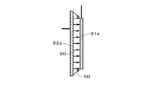
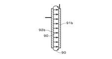
次に、金属空気電池における負極層と補助電極層との関係について述べる。図3.Aおよび図3.Bは比較例の金属空気電池における負極層および補助電極層を示す図であり、図1中の中心軸J1の左側における負極層3および補助電極層4に対応する図である。図3.Aおよび図3.Bでは、負極層91a,91bおよび補助電極層92a,92bのみを図示するとともに、充電時における電界の向きを符号90を付す矢印にて示す。   Next, the relationship between the negative electrode layer and the auxiliary electrode layer in the metal-air battery will be described. FIG. A and FIG. B is a diagram showing a negative electrode layer and an auxiliary electrode layer in a metal-air battery of a comparative example, and is a diagram corresponding to the negative electrode layer 3 and the auxiliary electrode layer 4 on the left side of the central axis J1 in FIG. FIG. A and FIG. In B, only the negative electrode layers 91a and 91b and the auxiliary electrode layers 92a and 92b are illustrated, and the direction of the electric field at the time of charging is indicated by an arrow with reference numeral 90.

図3.Aに示すように、補助電極層92aの上下方向の長さを負極層91aよりも長くする場合、負極層91aの上端部および下端部では、補助電極層92aとの間における電流密度が高くなり、電流集中が発生する。この場合、負極層91aの上端部および下端部において電解液中の金属が偏って析出し、補助電極層92aと負極層91aとが短絡する虞がある。また、図3.Bに示すように、補助電極層92bの上下方向の長さを負極層91bと等しくする場合においても、負極層91bの上端部および下端部では電流集中が発生し、金属が偏って析出してしまう。   FIG. As shown in A, when the vertical length of the auxiliary electrode layer 92a is made longer than that of the negative electrode layer 91a, the current density between the auxiliary electrode layer 92a and the upper end portion and the lower end portion of the negative electrode layer 91a is increased. , Current concentration occurs. In this case, there is a possibility that the metal in the electrolytic solution is unevenly deposited at the upper end and the lower end of the negative electrode layer 91a, and the auxiliary electrode layer 92a and the negative electrode layer 91a are short-circuited. In addition, FIG. As shown in B, even when the vertical length of the auxiliary electrode layer 92b is made equal to that of the negative electrode layer 91b, current concentration occurs at the upper end portion and the lower end portion of the negative electrode layer 91b, and the metal is unevenly deposited. End up.

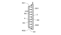
これに対し、金属空気電池1では、図4に示すように、補助電極層4(の補助導電層42)の上下方向の長さが負極層3(の負極導電層31)よりも短く、図1の円筒状の金属空気電池1では、内側に配置される負極層3の外側面30の面積が、外側に配置される補助電極層4の内側面40の面積よりも大きい。補助電極層4の内側面40および負極層3の外側面30をそれぞれ補助対向面40および負極対向面30として言い換えると、負極対向面30が、補助対向面40のエッジ部(図4では、補助対向面40の上端部401および下端部402)に対向する部位から外側に広がる部位301,302を有する。これにより、充電時に負極層3の上端部および下端部において、補助電極層4との間における電流密度が高くなることが防止される。その結果、負極層3の負極対向面30上に金属をほぼ均一に析出させることができ(金属が局所的に析出することが防止され)、負極層3と補助電極層4とが短絡することを防止することができる。   On the other hand, in the metal-air battery 1, as shown in FIG. 4, the vertical length of the auxiliary electrode layer 4 (the auxiliary conductive layer 42) is shorter than that of the negative electrode layer 3 (the negative electrode conductive layer 31). 1, the area of the outer surface 30 of the negative electrode layer 3 disposed on the inner side is larger than the area of the inner surface 40 of the auxiliary electrode layer 4 disposed on the outer side. In other words, the inner side surface 40 of the auxiliary electrode layer 4 and the outer side surface 30 of the negative electrode layer 3 are respectively referred to as the auxiliary facing surface 40 and the negative electrode facing surface 30, and the negative electrode facing surface 30 is the edge portion of the auxiliary facing surface 40 (in FIG. It has the part 301,302 which spreads outside from the part which opposes the upper end part 401 and the lower end part 402) of the opposing surface 40. As shown in FIG. This prevents the current density between the upper electrode layer 4 and the auxiliary electrode layer 4 from increasing at the upper end and the lower end of the negative electrode layer 3 during charging. As a result, the metal can be deposited almost uniformly on the negative electrode facing surface 30 of the negative electrode layer 3 (a metal is prevented from being deposited locally), and the negative electrode layer 3 and the auxiliary electrode layer 4 are short-circuited. Can be prevented.

また、負極層3が多孔質部材であることにより、活性な孔部にて金属が析出しやすくなり、負極層3上に金属が樹枝状に析出すること(いわゆる、デンドライトの発生)を抑制することができる。さらに、ステンレス鋼にて形成される補助電極層4では、炭素にて形成される電極を用いて充電する際における二酸化炭素の発生を抑制することができる。   Further, since the negative electrode layer 3 is a porous member, the metal is easily deposited in the active pores, and the metal is deposited on the negative electrode layer 3 in a dendritic manner (so-called dendrite generation) is suppressed. be able to. Furthermore, in the auxiliary electrode layer 4 formed of stainless steel, generation of carbon dioxide can be suppressed when charging is performed using an electrode formed of carbon.

金属空気電池1では、第1電解質層11に含まれる電解液に対する撥液性を有する撥液層21が、正極導電層22および正極触媒層23に対して第1電解質層11とは反対側に設けられることにより、仮に、電解液が正極触媒層23および正極導電層22を浸透(通過)したとしても、電解液が正極支持部61の内側に(すなわち、空気導入管5の近傍に)漏出することを防止することができる。さらに、撥液層21が多孔質部材であることにより、正極導電層22および正極触媒層23への空気の供給を可能としつつ、電解液の漏出(漏液)を防止することができる。   In the metal-air battery 1, the liquid repellent layer 21 having liquid repellency with respect to the electrolyte contained in the first electrolyte layer 11 is on the side opposite to the first electrolyte layer 11 with respect to the positive electrode conductive layer 22 and the positive electrode catalyst layer 23. By being provided, even if the electrolytic solution permeates (passes) the positive electrode catalyst layer 23 and the positive electrode conductive layer 22, the electrolytic solution leaks inside the positive electrode support portion 61 (that is, in the vicinity of the air introduction pipe 5). Can be prevented. Furthermore, since the liquid repellent layer 21 is a porous member, it is possible to prevent the electrolyte from leaking (leakage) while allowing air to be supplied to the positive electrode conductive layer 22 and the positive electrode catalyst layer 23.

補助電極層4では、電解液に対する撥液性を有するとともに多孔質部材である撥液層41が、補助導電層42の第2電解質層12とは反対側の面に設けられることにより、補助導電層42への空気の供給を可能としつつ、電解液が補助電極層4の外側に漏出することを防止することができる。   In the auxiliary electrode layer 4, the liquid repellent layer 41, which is liquid-repellent with respect to the electrolytic solution and is a porous member, is provided on the surface of the auxiliary conductive layer 42 opposite to the second electrolyte layer 12. While allowing air to be supplied to the layer 42, it is possible to prevent the electrolyte from leaking outside the auxiliary electrode layer 4.

金属空気電池1の設計によっては、第1および第2電解質層11,12の水系電解液に無機微粒子(フィラー)が添加されてもよい。無機微粒子としては、アルミナや二酸化ケイ素(SiO)、二酸化チタン(TiO)、ゼオライト、ペロブスカイト型酸化物等の無機酸化物が好ましく、特に、Si比が高い(例えば、Si/Alが2以上の)ゼオライト粒子がより好ましい。第1電解質層11の電解液が無機微粒子を含むことにより、金属空気電池1の内部抵抗が低減して電池容量が増大するとともに、金属空気電池1からの漏液が防止される。 Depending on the design of the metal-air battery 1, inorganic fine particles (filler) may be added to the aqueous electrolytes of the first and second electrolyte layers 11 and 12. As the inorganic fine particles, inorganic oxides such as alumina, silicon dioxide (SiO 2 ), titanium dioxide (TiO 2 ), zeolite, and perovskite oxide are preferable, and the Si ratio is particularly high (for example, Si / Al is 2 or more). Zeolite particles are preferred. When the electrolytic solution of the first electrolyte layer 11 contains inorganic fine particles, the internal resistance of the metal-air battery 1 is reduced, the battery capacity is increased, and leakage from the metal-air battery 1 is prevented.

以上、本発明の実施の形態について説明してきたが、本発明は上記実施の形態に限定されるものではなく、様々な変更が可能である。   As mentioned above, although embodiment of this invention has been described, this invention is not limited to the said embodiment, A various change is possible.

第1および第2電解質層11,12において固体電解質が用いられてもよい。また、撥液層は必要に応じて設けられるのみでよく、例えば、固体電解質が用いられる場合には省略可能である。負極層3の負極導電層31は、放電の際に酸化されて金属イオンを生成(放出)する金属を含む様々な材料により形成されてよい。   A solid electrolyte may be used in the first and second electrolyte layers 11 and 12. Further, the liquid repellent layer only needs to be provided as necessary, and can be omitted, for example, when a solid electrolyte is used. The negative electrode conductive layer 31 of the negative electrode layer 3 may be formed of various materials including a metal that is oxidized during discharge to generate (release) metal ions.

正極層2では、正極支持部61および撥液層21が導電性材料により形成されている場合、正極集電体24が省略されて正極支持部61の内側面に正極集電端子25が設けられてよい。また、正極導電層22がある程度の厚さを有している場合、正極導電層22を支持する正極支持部61は省略されてもよい。この場合、正極集電端子25は正極導電層22の内側面に設けられる。   In the positive electrode layer 2, when the positive electrode support 61 and the liquid repellent layer 21 are formed of a conductive material, the positive electrode current collector 24 is omitted and the positive electrode current collector terminal 25 is provided on the inner surface of the positive electrode support 61. It's okay. When the positive electrode conductive layer 22 has a certain thickness, the positive electrode support portion 61 that supports the positive electrode conductive layer 22 may be omitted. In this case, the positive electrode current collecting terminal 25 is provided on the inner surface of the positive electrode conductive layer 22.

金属空気電池では、正極支持部61の材料と正極導電層22の材料(すなわち、ペロブスカイト型酸化物)とが混合されたものから導電層が形成され、当該導電層上に正極触媒層23が形成されて正極層2とされてもよい。また、正極支持部61、正極導電層22および正極触媒層23の各材料が混合されたものから正極層2が形成されてもよい。いずれの場合であっても、正極層2が、導電性を有するペロブスカイト型酸化物、および、酸素還元反応を促進する触媒を含むとともに炭素を含んでいないため、金属空気電池の放電の際に、負極層3に含まれる金属の炭酸塩が正極層2上に生成されることを防止することができる。金属炭酸塩の生成が問題とならない場合には、正極導電層22は他の導電性材料にて形成されてもよい。   In the metal-air battery, a conductive layer is formed from a mixture of the material of the positive electrode support 61 and the material of the positive electrode conductive layer 22 (that is, a perovskite oxide), and the positive electrode catalyst layer 23 is formed on the conductive layer. And may be the positive electrode layer 2. Further, the positive electrode layer 2 may be formed from a mixture of the positive electrode support portion 61, the positive electrode conductive layer 22, and the positive electrode catalyst layer 23. In any case, since the positive electrode layer 2 contains a perovskite oxide having conductivity and a catalyst that promotes an oxygen reduction reaction and does not contain carbon, the metal-air battery is discharged at the time of discharge. The metal carbonate contained in the negative electrode layer 3 can be prevented from being formed on the positive electrode layer 2. In the case where generation of metal carbonate does not become a problem, the positive electrode conductive layer 22 may be formed of another conductive material.

上述の金属空気電池の構造は、例えば、平板状の金属空気電池に適用されてもよい。この場合も、負極対向面および補助対向面が互いに対向し、負極対向面が、補助対向面のエッジ部に対向する部位から外側に広がる部位(すなわち、互いに平行な両面の法線方向において、当該エッジ部と重なる負極対向面上の部位から、当該法線に垂直な方向に沿って当該エッジ部よりも外側へと広がる部位)を有することにより、充電時に負極層上に金属が局所的に析出することが防止される。以上のように、負極層と補助電極層との短絡が防止される金属空気電池は様々な形状にて実現可能である。ただし、正極層、負極層および補助電極層が筒状である場合には、活性かつデンドライトが生じやすいエッジ部を、平板状に比べて低減することができ(すなわち、エッジ部が上下端のみに制限される。)、デンドライトの発生をさらに抑制することが可能となる。   The structure of the metal-air battery described above may be applied to, for example, a flat metal-air battery. Also in this case, the negative electrode facing surface and the auxiliary facing surface face each other, and the negative electrode facing surface spreads outward from the portion facing the edge portion of the auxiliary facing surface (that is, in the normal direction of both surfaces parallel to each other) The metal is locally deposited on the negative electrode layer at the time of charging by having a part extending from the part on the negative electrode facing surface that overlaps the edge part to the outside of the edge part along the direction perpendicular to the normal line) Is prevented. As described above, the metal-air battery capable of preventing a short circuit between the negative electrode layer and the auxiliary electrode layer can be realized in various shapes. However, when the positive electrode layer, the negative electrode layer, and the auxiliary electrode layer are cylindrical, the active and easy-to-dendrite edge portions can be reduced compared to the flat plate shape (that is, the edge portions are only at the upper and lower ends). It is possible to further suppress the generation of dendrite.

上記実施の形態および各変形例における構成は、相互に矛盾しない限り適宜組み合わせられてよい。   The configurations in the above-described embodiments and modifications may be combined as appropriate as long as they do not contradict each other.

1 金属空気電池
2 正極層
3 負極層
4 補助電極層
11 第1電解質層
12 第2電解質層
22 正極導電層
23 正極触媒層
30 負極対向面
40 補助対向面
301,302 (外側に広がる)部位
401 上端部
402 下端部
DESCRIPTION OF SYMBOLS 1 Metal-air battery 2 Positive electrode layer 3 Negative electrode layer 4 Auxiliary electrode layer 11 1st electrolyte layer 12 2nd electrolyte layer 22 Positive electrode conductive layer 23 Positive electrode catalyst layer 30 Negative electrode opposing surface 40 Auxiliary opposing surface 301,302 (Expanded outside) 401 Upper end 402 Lower end

Claims (4)

金属空気電池であって、
金属を含む負極層と、
導電性材料、および、酸素還元反応を促進する触媒を含む多孔質の正極層と、
前記負極層と前記正極層との間に配置される第1電解質層と、
前記負極層の前記正極層とは反対側の面に対向する面を有する補助電極層と、
前記負極層と前記補助電極層との間に配置され、前記第1電解質層と連通する第2電解質層と、
を備え、
前記正極層、前記負極層および前記補助電極層が筒状であり、
前記負極層の前記面が、前記補助電極層の前記面のエッジ部に対向する部位から外側に広がる部位を有し、
充電の際に前記負極層と前記補助電極層との間にて電圧が付与されることにより前記負極層上に前記金属が析出することを特徴とする金属空気電池。
A metal-air battery,
A negative electrode layer containing a metal;
A porous positive electrode layer including a conductive material and a catalyst for promoting an oxygen reduction reaction;
A first electrolyte layer disposed between the negative electrode layer and the positive electrode layer;
An auxiliary electrode layer having a surface facing the surface of the negative electrode layer opposite to the positive electrode layer;
A second electrolyte layer disposed between the negative electrode layer and the auxiliary electrode layer and communicating with the first electrolyte layer;
With
The positive electrode layer, the negative electrode layer, and the auxiliary electrode layer are cylindrical,
The surface of the negative electrode layer has a portion that spreads outward from a portion facing the edge portion of the surface of the auxiliary electrode layer;
The metal-air battery, wherein the metal is deposited on the negative electrode layer by applying a voltage between the negative electrode layer and the auxiliary electrode layer during charging.
請求項1に記載の金属空気電池であって、
記正極層が前記負極層の内側に配置され、前記補助電極層が前記負極層の外側に配置されることを特徴とする金属空気電池。
The metal-air battery according to claim 1,
Before SL positive electrode layer is disposed on the inner side of the negative electrode layer, a metal-air battery, characterized in that said auxiliary electrode layer is disposed on the outside of the negative electrode layer.
属空気電池であって、
多孔質部材であり、金属を含む負極層と、
導電性材料、および、酸素還元反応を促進する触媒を含む多孔質の正極層と、
前記負極層と前記正極層との間に配置される第1電解質層と、
前記負極層の前記正極層とは反対側の面に対向する面を有する補助電極層と、
前記負極層と前記補助電極層との間に配置され、前記第1電解質層と連通する第2電解質層と、
を備え、
前記負極層の前記面が、前記補助電極層の前記面のエッジ部に対向する部位から外側に広がる部位を有し、
充電の際に前記負極層と前記補助電極層との間にて電圧が付与されることにより前記負極層上に前記金属が析出することを特徴とする金属空気電池。
A metallic air battery,
Porous member der is, a negative electrode layer containing a metal,
A porous positive electrode layer including a conductive material and a catalyst for promoting an oxygen reduction reaction;
A first electrolyte layer disposed between the negative electrode layer and the positive electrode layer;
An auxiliary electrode layer having a surface facing the surface of the negative electrode layer opposite to the positive electrode layer;
A second electrolyte layer disposed between the negative electrode layer and the auxiliary electrode layer and communicating with the first electrolyte layer;
With
The surface of the negative electrode layer has a portion that spreads outward from a portion facing the edge portion of the surface of the auxiliary electrode layer;
The metal-air battery, characterized that you said metal deposited on the negative electrode layer when a voltage is applied in between the negative electrode layer and the auxiliary electrode layer during charging.
請求項1ないし3のいずれかに記載の金属空気電池であって、
前記導電性材料がペロブスカイト型酸化物であり、前記正極層が炭素を含まないことを特徴とする金属空気電池。
The metal-air battery according to any one of claims 1 to 3,
The metal-air battery, wherein the conductive material is a perovskite oxide and the positive electrode layer does not contain carbon.
JP2011071500A 2010-06-04 2011-03-29 Metal air battery Expired - Fee Related JP5773699B2 (en)

Priority Applications (6)

Application Number Priority Date Filing Date Title
JP2011071500A JP5773699B2 (en) 2011-03-29 2011-03-29 Metal air battery
CN2011800274665A CN102934280A (en) 2010-06-04 2011-06-01 Metal air battery
PCT/JP2011/062616 WO2011152464A1 (en) 2010-06-04 2011-06-01 Metal air battery
KR1020127031693A KR20130112697A (en) 2010-06-04 2011-06-01 Metal air battery
US13/700,253 US20130078535A1 (en) 2010-06-04 2011-06-01 Metal-air battery
US13/934,510 US20130295472A1 (en) 2010-06-04 2013-07-03 Metal-air battery

Applications Claiming Priority (1)

Application Number Priority Date Filing Date Title
JP2011071500A JP5773699B2 (en) 2011-03-29 2011-03-29 Metal air battery

Publications (3)

Publication Number Publication Date
JP2012209020A JP2012209020A (en) 2012-10-25
JP2012209020A5 JP2012209020A5 (en) 2014-02-13
JP5773699B2 true JP5773699B2 (en) 2015-09-02

Family

ID=47188603

Family Applications (1)

Application Number Title Priority Date Filing Date
JP2011071500A Expired - Fee Related JP5773699B2 (en) 2010-06-04 2011-03-29 Metal air battery

Country Status (1)

Country Link
JP (1) JP5773699B2 (en)

Families Citing this family (8)

* Cited by examiner, † Cited by third party
Publication number Priority date Publication date Assignee Title
US9553328B2 (en) * 2013-08-26 2017-01-24 e-Zn Inc. Electrochemical system for storing electricity in metals
JP6353243B2 (en) * 2014-03-05 2018-07-04 シャープ株式会社 Metal air battery
JP6596213B2 (en) * 2014-11-17 2019-10-23 日立造船株式会社 Metal air battery
WO2016080115A1 (en) * 2014-11-17 2016-05-26 日立造船株式会社 Metal-air battery
JP6560025B2 (en) * 2015-05-20 2019-08-14 株式会社日本触媒 Air metal battery
JP6560028B2 (en) * 2015-06-04 2019-08-14 株式会社日本触媒 Electrode for air metal battery and air metal battery
JP6562739B2 (en) * 2015-07-01 2019-08-21 日立造船株式会社 Electrode and metal-air secondary battery
JP6902837B2 (en) * 2016-08-25 2021-07-14 シャープ株式会社 Metal-air battery

Family Cites Families (3)

* Cited by examiner, † Cited by third party
Publication number Priority date Publication date Assignee Title
JPS4947851A (en) * 1972-09-14 1974-05-09
JPH0417259A (en) * 1990-05-10 1992-01-22 Matsushita Electric Ind Co Ltd Battery
JP5215146B2 (en) * 2008-12-03 2013-06-19 日本電信電話株式会社 Lithium air secondary battery and method for producing lithium air secondary battery

Also Published As

Publication number Publication date
JP2012209020A (en) 2012-10-25

Similar Documents

Publication Publication Date Title
JP5773699B2 (en) Metal air battery
US20130078535A1 (en) Metal-air battery
JP2011253789A (en) Metal-air battery
JP4186810B2 (en) Fuel cell manufacturing method and fuel cell
EP3046171B1 (en) Fuel cell and fuel cell stack
JP5904854B2 (en) Metal air battery
KR20120040449A (en) Solid oxide electrolyte membrane, manufacturing method thereof, and fuel cell employing the same
JP2012104273A (en) Metal air battery
JP2016157693A (en) Solid oxide fuel battery single cell and solid oxide fuel battery stack
CN107408745B (en) metal air battery
JP5199218B2 (en) Solid oxide fuel cell and manufacturing method thereof
KR20190034027A (en) Lithum ion battery including nano-crystalline graphene electrode
JP2008226478A (en) Solid oxide fuel cell and manufacturing method thereof
JP5233143B2 (en) Solid oxide fuel cell
JP5352943B2 (en) Solid oxide fuel cell and stack structure thereof
KR101188997B1 (en) Solid oxide fuel cell
JP6166929B2 (en) Metal-air secondary battery
JP2007012361A (en) Solid oxide fuel cell
US20130171539A1 (en) Tubular solid oxide fuel cell module and method of manufacturing the same
JP6068228B2 (en) Separator, metal-air secondary battery, and separator manufacturing method
JP5273584B2 (en) Solid oxide fuel cell, solid oxide fuel cell unit, and fuel cell module including the same
JP2007207679A (en) Hollow platinum catalyst particles for fuel cells, membrane electrode assemblies, production methods thereof, and fuel cells
JP2015185235A (en) Electrode and secondary battery
JP5387821B2 (en) Flat type solid oxide fuel cell
JP5708541B2 (en) Tubular fuel cell connection structure and connection method, and secondary battery type fuel cell system

Legal Events

Date Code Title Description
A521 Written amendment

Free format text: JAPANESE INTERMEDIATE CODE: A523

Effective date: 20131224

A621 Written request for application examination

Free format text: JAPANESE INTERMEDIATE CODE: A621

Effective date: 20131224

A131 Notification of reasons for refusal

Free format text: JAPANESE INTERMEDIATE CODE: A131

Effective date: 20141211

A521 Written amendment

Free format text: JAPANESE INTERMEDIATE CODE: A523

Effective date: 20150128

TRDD Decision of grant or rejection written
A01 Written decision to grant a patent or to grant a registration (utility model)

Free format text: JAPANESE INTERMEDIATE CODE: A01

Effective date: 20150611

A61 First payment of annual fees (during grant procedure)

Free format text: JAPANESE INTERMEDIATE CODE: A61

Effective date: 20150630

R150 Certificate of patent or registration of utility model

Ref document number: 5773699

Country of ref document: JP

Free format text: JAPANESE INTERMEDIATE CODE: R150

LAPS Cancellation because of no payment of annual fees