JP6596213B2 - Metal air battery - Google Patents
Metal air battery Download PDFInfo
- Publication number
- JP6596213B2 JP6596213B2 JP2015068952A JP2015068952A JP6596213B2 JP 6596213 B2 JP6596213 B2 JP 6596213B2 JP 2015068952 A JP2015068952 A JP 2015068952A JP 2015068952 A JP2015068952 A JP 2015068952A JP 6596213 B2 JP6596213 B2 JP 6596213B2
- Authority
- JP
- Japan
- Prior art keywords
- positive electrode
- metal
- ceramic
- air battery
- catalyst layer
- Prior art date
- Legal status (The legal status is an assumption and is not a legal conclusion. Google has not performed a legal analysis and makes no representation as to the accuracy of the status listed.)
- Expired - Fee Related
Links
Images


Classifications
-
- H—ELECTRICITY
- H01—ELECTRIC ELEMENTS
- H01M—PROCESSES OR MEANS, e.g. BATTERIES, FOR THE DIRECT CONVERSION OF CHEMICAL ENERGY INTO ELECTRICAL ENERGY
- H01M12/00—Hybrid cells; Manufacture thereof
- H01M12/08—Hybrid cells; Manufacture thereof composed of a half-cell of a fuel-cell type and a half-cell of the secondary-cell type
-
- H—ELECTRICITY
- H01—ELECTRIC ELEMENTS
- H01M—PROCESSES OR MEANS, e.g. BATTERIES, FOR THE DIRECT CONVERSION OF CHEMICAL ENERGY INTO ELECTRICAL ENERGY
- H01M4/00—Electrodes
- H01M4/86—Inert electrodes with catalytic activity, e.g. for fuel cells
-
- H—ELECTRICITY
- H01—ELECTRIC ELEMENTS
- H01M—PROCESSES OR MEANS, e.g. BATTERIES, FOR THE DIRECT CONVERSION OF CHEMICAL ENERGY INTO ELECTRICAL ENERGY
- H01M4/00—Electrodes
- H01M4/86—Inert electrodes with catalytic activity, e.g. for fuel cells
- H01M4/90—Selection of catalytic material
-
- H—ELECTRICITY
- H01—ELECTRIC ELEMENTS
- H01M—PROCESSES OR MEANS, e.g. BATTERIES, FOR THE DIRECT CONVERSION OF CHEMICAL ENERGY INTO ELECTRICAL ENERGY
- H01M4/00—Electrodes
- H01M4/86—Inert electrodes with catalytic activity, e.g. for fuel cells
- H01M4/90—Selection of catalytic material
- H01M4/9016—Oxides, hydroxides or oxygenated metallic salts
- H01M4/9025—Oxides specially used in fuel cell operating at high temperature, e.g. SOFC
- H01M4/9033—Complex oxides, optionally doped, of the type M1MeO3, M1 being an alkaline earth metal or a rare earth, Me being a metal, e.g. perovskites
-
- H—ELECTRICITY
- H01—ELECTRIC ELEMENTS
- H01M—PROCESSES OR MEANS, e.g. BATTERIES, FOR THE DIRECT CONVERSION OF CHEMICAL ENERGY INTO ELECTRICAL ENERGY
- H01M50/00—Constructional details or processes of manufacture of the non-active parts of electrochemical cells other than fuel cells, e.g. hybrid cells
- H01M50/40—Separators; Membranes; Diaphragms; Spacing elements inside cells
- H01M50/409—Separators, membranes or diaphragms characterised by the material
- H01M50/431—Inorganic material
- H01M50/434—Ceramics
-
- H—ELECTRICITY
- H01—ELECTRIC ELEMENTS
- H01M—PROCESSES OR MEANS, e.g. BATTERIES, FOR THE DIRECT CONVERSION OF CHEMICAL ENERGY INTO ELECTRICAL ENERGY
- H01M50/00—Constructional details or processes of manufacture of the non-active parts of electrochemical cells other than fuel cells, e.g. hybrid cells
- H01M50/40—Separators; Membranes; Diaphragms; Spacing elements inside cells
- H01M50/409—Separators, membranes or diaphragms characterised by the material
- H01M50/443—Particulate material
-
- H—ELECTRICITY
- H01—ELECTRIC ELEMENTS
- H01M—PROCESSES OR MEANS, e.g. BATTERIES, FOR THE DIRECT CONVERSION OF CHEMICAL ENERGY INTO ELECTRICAL ENERGY
- H01M50/00—Constructional details or processes of manufacture of the non-active parts of electrochemical cells other than fuel cells, e.g. hybrid cells
- H01M50/40—Separators; Membranes; Diaphragms; Spacing elements inside cells
- H01M50/489—Separators, membranes, diaphragms or spacing elements inside the cells, characterised by their physical properties, e.g. swelling degree, hydrophilicity or shut down properties
-
- Y—GENERAL TAGGING OF NEW TECHNOLOGICAL DEVELOPMENTS; GENERAL TAGGING OF CROSS-SECTIONAL TECHNOLOGIES SPANNING OVER SEVERAL SECTIONS OF THE IPC; TECHNICAL SUBJECTS COVERED BY FORMER USPC CROSS-REFERENCE ART COLLECTIONS [XRACs] AND DIGESTS
- Y02—TECHNOLOGIES OR APPLICATIONS FOR MITIGATION OR ADAPTATION AGAINST CLIMATE CHANGE
- Y02E—REDUCTION OF GREENHOUSE GAS [GHG] EMISSIONS, RELATED TO ENERGY GENERATION, TRANSMISSION OR DISTRIBUTION
- Y02E60/00—Enabling technologies; Technologies with a potential or indirect contribution to GHG emissions mitigation
- Y02E60/10—Energy storage using batteries
Description
本発明は、金属空気電池に関する。 The present invention relates to a metal-air battery.
従来より、負極と正極との間にセパレータを配置した金属空気電池が知られている。例えば、特許文献1では、負極と正極との間に配置されるセパレータにおいて、セラミックにて形成される多孔質の支持体であるセパレータ本体と、セパレータ本体において負極と対向する面上にセラミックにて形成され、セパレータ本体の平均細孔径よりも小さい平均細孔径を有する多孔膜とが設けられる。特許文献1では、多孔膜の平均細孔径が、0.01μm(マイクロメートル)以上かつ2μm以下であり、多孔膜の厚さが50μm以上かつ200μm以下であることにより、負極の析出金属がセパレータを貫通することが防止される。
Conventionally, a metal-air battery in which a separator is disposed between a negative electrode and a positive electrode is known. For example, in
なお、特許文献2におけるリチウム二次電池では、セパレータがセラミック物質とバインダとにより形成される多孔膜を含み、当該バインダが3次元架橋構造を有するアクリル系ゴムにて構成される。また、特許文献3では、ペロブスカイト型酸化物の組成物を変えて、酸素還元に有効に働くものと、酸素発生に有効に働くものとを使用した二次電池用電極が開示されている。さらに、特許文献4では、酸素極層が二層構造を有している燃料電池セルが開示されており、当該酸素極層は、平均粒径が2μm以下の導電性セラミックの微細粒子からなる反応層と、平均粒径が10〜100μmの導電性セラミックの粗大粒子からなるガス供給層とからなる。 In the lithium secondary battery in Patent Document 2, the separator includes a porous film formed of a ceramic material and a binder, and the binder is made of acrylic rubber having a three-dimensional crosslinked structure. Patent Document 3 discloses an electrode for a secondary battery using a composition that works effectively for oxygen reduction and a composition that works effectively for oxygen generation by changing the composition of the perovskite oxide. Further, Patent Document 4 discloses a fuel cell in which the oxygen electrode layer has a two-layer structure, and the oxygen electrode layer is a reaction made of fine particles of conductive ceramic having an average particle size of 2 μm or less. And a gas supply layer made of coarse particles of conductive ceramic having an average particle diameter of 10 to 100 μm.
ところで、セパレータを支持体とする金属空気電池では、例えば、支持体の表面に所定のセラミックを含む材料を成膜して焼成することにより、正極導電層や正極触媒層が形成される。このような金属空気電池において、正極の厚さを大きくする場合には、成膜および焼成を繰り返す必要があり、金属空気電池の製造に長時間を要してしまう。また、セパレータの材料と、正極導電層や正極触媒層の材料との間に大きな熱膨張係数差がある場合には、焼成の際に、クラックや剥離が生じてしまう。したがって、セパレータを支持体とする金属空気電池では、正極を厚くすることが困難であり、正極の電気抵抗を低くして電池性能を向上することができない。 By the way, in the metal air battery which uses a separator as a support, for example, a positive electrode conductive layer and a positive electrode catalyst layer are formed by forming and firing a material containing a predetermined ceramic on the surface of the support. In such a metal-air battery, in order to increase the thickness of the positive electrode, it is necessary to repeat film formation and firing, and it takes a long time to manufacture the metal-air battery. Further, when there is a large difference in thermal expansion coefficient between the material of the separator and the material of the positive electrode conductive layer or the positive electrode catalyst layer, cracking or peeling occurs during firing. Therefore, in a metal-air battery using a separator as a support, it is difficult to increase the thickness of the positive electrode, and the battery performance cannot be improved by reducing the electrical resistance of the positive electrode.
本発明は上記課題に鑑みなされたものであり、電池性能を向上することを目的としている。 This invention is made | formed in view of the said subject, and aims at improving battery performance.
請求項1に記載の発明は、金属空気電池であって、筒状の正極と、前記正極の内側面または外側面に対向する負極と、前記負極と前記正極との間に配置される電解質層とを備え、前記正極が、導電性セラミックにて形成された筒状の支持体である多孔質の正極本体を有し、前記正極本体の内側面または外側面であって、前記負極側の面に、セパレータである多孔膜が絶縁性のセラミックにて形成される。
The invention according to
請求項2に記載の発明は、請求項1に記載の金属空気電池であって、前記正極本体の厚さが、前記セパレータの厚さよりも大きい。
The invention according to claim 2 is the metal-air battery according to
請求項3に記載の発明は、請求項1または2に記載の金属空気電池であって、前記正極本体の前記負極とは反対側の面に、正極触媒層であるもう1つの多孔膜がセラミックにて形成され、前記多孔膜が前記正極本体の前記内側面に形成され、前記もう1つの多孔膜が前記正極本体の前記外側面に形成される。 A third aspect of the present invention is the metal-air battery according to the first or second aspect , wherein the other porous membrane as the positive electrode catalyst layer is formed on the surface of the positive electrode body opposite to the negative electrode. The porous film is formed on the inner surface of the positive electrode body, and the other porous film is formed on the outer surface of the positive electrode body.
請求項4に記載の発明は、請求項3に記載の金属空気電池であって、前記正極触媒層の前記セラミックが前記正極本体の前記導電性セラミックと同じ結晶構造を有する。 The invention according to claim 4 is the metal-air battery according to claim 3 , wherein the ceramic of the positive electrode catalyst layer has the same crystal structure as that of the conductive ceramic of the positive electrode main body.
請求項5に記載の発明は、請求項3または4に記載の金属空気電池であって、前記正極触媒層の前記セラミックが、前記正極本体の前記導電性セラミックよりも酸素還元反応に優れ、前記正極本体の前記導電性セラミックが、前記正極触媒層の前記セラミックよりも酸素発生反応に優れる。
請求項6に記載の発明は、金属空気電池であって、筒状の正極と、前記正極の内側面または外側面に対向する負極と、前記負極と前記正極との間に配置される電解質層とを備え、前記正極が、導電性セラミックにて形成された筒状の支持体である多孔質の正極本体を有し、前記正極本体の内側面または外側面であって、前記負極とは反対側の面に、正極触媒層である多孔膜がセラミックにて形成され、前記正極触媒層の前記セラミックが前記正極本体の前記導電性セラミックと同じ結晶構造を有する。
請求項7に記載の発明は、金属空気電池であって、筒状の正極と、前記正極の内側面または外側面に対向する負極と、前記負極と前記正極との間に配置される電解質層とを備え、前記正極が、導電性セラミックにて形成された筒状の支持体である多孔質の正極本体を有し、前記正極本体の内側面または外側面であって、前記負極とは反対側の面に、正極触媒層である多孔膜がセラミックにて形成され、前記正極触媒層の前記セラミックが、前記正極本体の前記導電性セラミックよりも酸素還元反応に優れ、前記正極本体の前記導電性セラミックが、前記正極触媒層の前記セラミックよりも酸素発生反応に優れる。
Invention of Claim 5 is a metal air battery of Claim 3 or 4 , Comprising: The said ceramic of the said positive electrode catalyst layer is excellent in oxygen reduction reaction rather than the said electroconductive ceramic of the said positive electrode main body, The said The conductive ceramic of the positive electrode main body is superior in oxygen generation reaction than the ceramic of the positive electrode catalyst layer.
The invention according to claim 6 is a metal-air battery, wherein a cylindrical positive electrode, a negative electrode facing an inner surface or an outer surface of the positive electrode, and an electrolyte layer disposed between the negative electrode and the positive electrode The positive electrode has a porous positive electrode body that is a cylindrical support formed of a conductive ceramic, and is an inner surface or an outer surface of the positive electrode body, opposite to the negative electrode A porous film which is a positive electrode catalyst layer is formed of ceramic on the side surface, and the ceramic of the positive electrode catalyst layer has the same crystal structure as that of the conductive ceramic of the positive electrode body.
The invention according to claim 7 is a metal-air battery, wherein a cylindrical positive electrode, a negative electrode facing an inner surface or an outer surface of the positive electrode, and an electrolyte layer disposed between the negative electrode and the positive electrode The positive electrode has a porous positive electrode body that is a cylindrical support formed of a conductive ceramic, and is an inner surface or an outer surface of the positive electrode body, opposite to the negative electrode On the side surface, a porous film that is a positive electrode catalyst layer is formed of ceramic, and the ceramic of the positive electrode catalyst layer is superior in oxygen reduction reaction than the conductive ceramic of the positive electrode body, and the conductive material of the positive electrode body. The superior ceramic is more excellent in oxygen generation reaction than the ceramic of the positive electrode catalyst layer.
本発明によれば、正極本体を支持体とすることにより、正極を容易に厚くすることができ、正極の電気抵抗を低くして、電池性能を向上することができる。 According to the present invention, by using the positive electrode main body as a support, the positive electrode can be easily thickened, the electric resistance of the positive electrode can be lowered, and the battery performance can be improved.
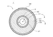
図1は、本発明の一の実施の形態に係る金属空気電池1の構成を示す図である。図1の金属空気電池1は亜鉛イオンを利用する二次電池であり、亜鉛空気二次電池である。金属空気電池は、他の金属イオンを利用してもよい。金属空気電池1の本体11は中心軸J1を中心とする略円柱状であり、図1では、中心軸J1に垂直な面における本体11の断面(後述の負極3を除く。)を示す。金属空気電池1は、正極2、負極3および電解質層4を備える。
FIG. 1 is a diagram showing a configuration of a metal-
負極3(金属極とも呼ばれる。)は、中心軸J1を中心とするコイル状の部材である。本実施の形態における負極3は、断面が略円形の線状の部材を中心軸J1を中心として螺旋状に巻いた形状を有する。負極3は、導電性材料にて形成されるコイル状の基材、および、基材の表面に形成される析出金属層を備える。中心軸J1方向における負極3の端部には負極集電端子(図示省略)が接続される。 The negative electrode 3 (also referred to as a metal electrode) is a coiled member centered on the central axis J1. The negative electrode 3 in the present embodiment has a shape in which a linear member having a substantially circular cross section is spirally wound around the central axis J1. The negative electrode 3 includes a coiled base material formed of a conductive material and a deposited metal layer formed on the surface of the base material. A negative electrode current collector terminal (not shown) is connected to the end of the negative electrode 3 in the direction of the central axis J1.
上記基材を形成する材料として、銅(Cu)、ニッケル(Ni)、銀(Ag)、金(Au)、鉄(Fe)、アルミニウム(Al)、マグネシウム(Mg)等の金属、または、いずれかの金属を含む合金が例示される。本実施の形態では、基材は銅にて形成される。集電体を兼ねる基材の導電率を高くするという観点では、基材は銅または銅合金を含むことが好ましい。基材の本体が銅にて形成される場合、当該本体の表面にニッケル等の他の金属の保護膜が形成されることが好ましい。この場合、基材の表面は、当該保護膜の表面となる。例えば、保護膜の厚さは、1〜20μm(マイクロメートル)であり、保護膜は、めっきにて形成される。析出金属層は、亜鉛(Zn)の電解析出により形成される。析出金属層は、亜鉛を含む合金の電解析出にて形成されてもよい。金属空気電池1の設計によっては、筒状または棒状の負極3が利用されてもよい。
As a material for forming the substrate, a metal such as copper (Cu), nickel (Ni), silver (Ag), gold (Au), iron (Fe), aluminum (Al), magnesium (Mg), or any An alloy containing such a metal is exemplified. In the present embodiment, the base material is formed of copper. From the viewpoint of increasing the conductivity of the base material also serving as a current collector, the base material preferably contains copper or a copper alloy. When the main body of the substrate is formed of copper, it is preferable that a protective film of other metal such as nickel is formed on the surface of the main body. In this case, the surface of the substrate is the surface of the protective film. For example, the thickness of the protective film is 1 to 20 μm (micrometer), and the protective film is formed by plating. The deposited metal layer is formed by electrolytic deposition of zinc (Zn). The deposited metal layer may be formed by electrolytic deposition of an alloy containing zinc. Depending on the design of the metal-
負極3の周囲には、円筒状のセパレータ41が設けられ、セパレータ41の周囲には、円筒状の正極2(空気極とも呼ばれる。)が設けられる。すなわち、セパレータ41の内側面は負極3に対向し、セパレータ41の外側面は正極2の内側面に対向する。負極3、セパレータ41および正極2は、中心軸J1を中心とする同心状に設けられ、中心軸J1に沿って見た場合に、負極3の外縁と正極2との間の距離は、中心軸J1を中心とする周方向の全周に亘って一定である。すなわち、金属空気電池1における負極3および正極2の間では、全周に亘って、等電位面の間隔が一定である。等電位面に粗密がないため、充放電時の電流分布は周方向において一定となる。なお、全周に亘る電流分布がおよそ均一となるのであるならば、正極2の形状は、例えば、頂点が6個以上の正多角形の筒状であってもよい。セパレータ41の詳細については後述する。
A
正極2は、導電性セラミックにて形成された筒状の支持体である多孔質の正極本体21、および、正極本体21の負極3とは反対側の外側面に形成された正極触媒層22を有する。好ましくは、正極触媒層22は、正極本体21の全周に亘って形成される。正極触媒層22の外側面の一部には、耐アルカリ性を有するセラミックにて形成されるインターコネクタ24が設けられる。インターコネクタ24の厚さは、例えば約30〜300μmである。インターコネクタ24には正極集電端子(図示省略)が接続される。正極触媒層22の外側面において、インターコネクタ24にて覆われていない領域には、撥水性を有する材料(例えば、FEP(テトラフルオロエチレン・ヘキサフルオロプロピレン共重合体)やPTFE(ポリテトラフルオロエチレン))による多孔質の層が撥液層29として形成される。撥液層29は、高いガス透過性および高い液不透過性を有する。
The positive electrode 2 includes a porous positive electrode
正極導電層である正極本体21は、導電性セラミックを含む材料の押出成形および焼成により形成される。導電性セラミックとして、好ましくは、導電性を有するペロブスカイト型酸化物またはスピネル型酸化物が利用される。本実施の形態では、正極本体21は、ペロブスカイト型酸化物(例えば、LSM(LaSrMnO3)、LSMF(LaSrMnFeO3)、あるいは、LSCF(LaSrCoFeO3))にて形成される。正極本体21において利用されるペロブスカイト型酸化物は、Co、Mn、Feのうちの少なくとも1種を含むことが好ましい。充電時における酸化による劣化を防止するという観点では、正極本体21は、導電性カーボンを含まないことが好ましい。正極本体21は、他の導電性セラミックにより形成されてよい。正極本体21のガス透過量は、2000m3/(m2・h・atm)以上であることが好ましく、この場合、正極本体21の空孔率は、30%以上であることが好ましい。空孔率が30%よりも小さい場合、ガス透過性が過度に低くなる。また、正極本体21の空孔率は、80%以下であることが好ましい。空孔率が80%よりも大きい場合、正極本体21の支持体としての強度が低下する。
The positive electrode
また、正極触媒層22は、ペロブスカイト型酸化物(例えば、LSM、LSCF、あるいは、LSMF)等の導電性セラミックの粉体を、例えばスラリーコート法および焼成により、正極本体21上に担持させた部位を含む。正極触媒層22は、正極本体21の負極3とは反対側の外側面上にセラミックにて形成された多孔膜であり、支持体である正極本体21により支持される。例えば、正極触媒層22の厚さは、正極本体21の厚さよりも十分に小さい。金属空気電池1では、原則として、多孔質の正極触媒層22近傍において空気と後述の電解液40との界面が形成される。
The positive
既述のセパレータ41は、正極本体21の負極3側の内側面に形成される多孔膜であり、当該内側面の全周に亘って形成される。セパレータ41は、例えば、シリカ(SiO2)、アルミナ(Al2O3)、ジルコニア(ZrO2)、チタニア(TiO2)、ハフニア(HfO2)およびセリア(CeO2)等の機械的強度および絶縁性が高いセラミック粉末の焼結体であり、耐アルカリ性を有する。後述するように、セパレータ41の作製では、正極本体21の内側面にスラリーコート法等により上記セラミック粉末およびバインダを含むスラリーを成膜して乾燥し、高温の焼成によりスラリーに含まれるバインダが除去される。これにより、バインダの劣化によりセパレータの寿命が短くなることが防止される。セパレータ41は、セラミックのみにて構成されることが好ましい。セパレータ41は、これらのセラミックの混合体や積層体であってもよい。
The
上記セラミック粉末の平均粒子径は、好ましくは、0.1μm以上、かつ、30μm以下であり、必要に応じて分級加工により粒子径が揃えられる。セパレータ41の平均細孔径は0.01μm以上、2μm以下であることが好ましい。これにより、負極3の析出金属(デンドライト等)がセパレータ41を貫通することが防止される。セパレータ41の平均細孔径は、正極本体21の平均細孔径よりも小さいことが好ましい。また、円筒状のセパレータ41の厚さ(肉厚)は50μm以上、200μm以下であり、正極本体21の厚さよりも小さいことが好ましい。
The average particle size of the ceramic powder is preferably 0.1 μm or more and 30 μm or less, and the particle size is adjusted by classification as necessary. The average pore diameter of the
筒状の正極2の内側(中心軸J1側)の空間には、水系の電解液40が充填される。電解液40は、正極2と負極3との間に介在し、両極に接する。負極3のおよそ全体は電解液40中に浸漬される。多孔質のセパレータ41、および、正極本体21の細孔にも電解液40が充填される。さらに、正極触媒層22の一部の細孔にも電解液40が充填される。以下の説明では、中心軸J1に沿って見た場合における負極3と正極2との間の空間を「電解質層4」という。すなわち、電解質層4は、負極3と正極2との間に配置される。本実施の形態では、電解質層4はセパレータ41を含む。
A space on the inner side (center axis J1 side) of the cylindrical positive electrode 2 is filled with an
電解液40は、アルカリ水溶液であり、好ましくは、水酸化カリウム(苛性カリ、KOH)水溶液、または、水酸化ナトリウム(苛性ソーダ、NaOH)水溶液を含む。また、電解液40は、亜鉛イオンまたは亜鉛を含むイオンを含む。すなわち、電解液40に含まれる亜鉛イオンは、様々な態様で存在してよく、亜鉛(すなわち、亜鉛原子)を含むイオンと捉えられてもよい。例えば、テトラヒドロキシ亜鉛イオンとして存在してもよい。
The
中心軸J1方向において負極3、電解質層4および正極2の両端面には、円板状の閉塞部材が固定される。各閉塞部材の中央には貫通孔が設けられる。金属空気電池1では、撥液層29および閉塞部材により、本体11内の電解液40が上記貫通孔以外から外部へと漏出することが防止される。また、両端面上の閉塞部材の貫通孔を利用して、本体11と図示省略の貯溜タンクとの間にて電解液を循環させることが可能である。
Disc-shaped closing members are fixed to both end faces of the negative electrode 3, the electrolyte layer 4, and the positive electrode 2 in the direction of the central axis J <b> 1. A through hole is provided in the center of each closing member. In the metal-
図1の金属空気電池1において放電が行われる際には、負極集電端子と正極集電端子とが、例えば、照明器具等の負荷を介して電気的に接続される。負極3が有する亜鉛は酸化されて亜鉛イオンが生成され、電子は負極集電端子、および、正極集電端子を介して正極2に供給される。多孔質の正極2では、撥液層29を透過した空気中の酸素が、負極3から供給された電子により還元され、水酸化物イオンとして電解液中に溶出する。正極2では、正極触媒により酸素の還元反応が促進される。
When discharge is performed in the metal-
一方、金属空気電池1において充電が行われる際には、負極集電端子と正極集電端子との間に電圧が付与され、正極2に対して水酸化物イオンから電子が供給されるとともに酸素が発生する。負極3では、正極集電端子を介して負極集電端子に供給される電子により金属イオンが還元されて亜鉛が析出する。
On the other hand, when the metal-
このとき、コイル状の負極3では、角部がないため、電界集中が起こりにくい。すなわち、電流密度に大きな偏りが生じない。また、負極3が、電解液40に均一に接触する。その結果、亜鉛が樹枝状に析出するデンドライトや、ひげ状(針状)に析出するウィスカーの生成および成長が大きく抑制される。実際には、負極3の表面のほぼ全体において緻密な亜鉛が均一に析出し、析出金属層が形成される。正極2では、正極触媒層22に含まれる正極触媒により酸素の発生が促進される。さらに、正極2では、カーボン素材を用いていないことにより、充電時に発生する酸素による酸化劣化が生じることはない。
At this time, since the coiled negative electrode 3 has no corners, electric field concentration hardly occurs. That is, there is no significant bias in current density. Further, the negative electrode 3 is in uniform contact with the
上述のように、金属空気電池1では、正極本体21を支持体として、正極本体21の外側面に正極触媒層22が形成され、正極本体21の内側面にセパレータ41が形成される。すなわち、セパレータ41および正極2が一繋がりの部材として作製される。図2は、セパレータ41が設けられた正極2を作製する流れを示す図である。図2は、正極2の作製の基本的な流れを示すものであり、処理順序は適宜変更されてよい。
As described above, in the metal-
正極2の作製では、まず、導電性セラミックを含む正極形成材料の押出成形および焼成により円筒状の正極本体21が多孔質の支持体として形成される(ステップS11)。導電性セラミックとして、例えば、ペロブスカイト型酸化物が利用され、ここでは、LSMまたはLSCFが利用される。正極導電層である正極本体21において高い導電性を確保し、かつ、酸素発生反応触媒としての機能も確保するという観点では、LSCFを利用することが好ましい。
In the production of the positive electrode 2, first, the cylindrical positive electrode
焼成の前に、成形体を100〜800℃で加熱処理して成形体中の有機成分を分解除去してもよい。焼成は、成形体が十分に焼結し、かつ、ガス透過性や電解液浸透性、電池性能を保持できる条件であればよく、900〜1500℃で行われることが好ましい。また、成形体を後述の他の層と共焼成してもよい。共焼成を行うことにより、成形体と当該層との間の接着強度を向上させることができる。また、各層を個別に焼成する場合に比べて、焼成工程のリードタイムを低減することができる。正極本体21は、押出成形および焼成以外の手法にて形成されてよい。
Prior to firing, the molded body may be heat-treated at 100 to 800 ° C. to decompose and remove organic components in the molded body. The firing is preferably performed at 900 to 1500 ° C. as long as the molded body is sufficiently sintered and can maintain gas permeability, electrolyte solution permeability, and battery performance. Moreover, you may co-fire a molded object with the other layer mentioned later. By performing co-firing, the adhesive strength between the molded body and the layer can be improved. Moreover, the lead time of a baking process can be reduced compared with the case where each layer is baked separately. The positive electrode
正極本体21が準備されると、正極本体21の外側面にスラリーコート法により正極触媒を含むスラリーを成膜し、正極本体21と共に焼成することにより、正極触媒層22が形成される(ステップS12)。正極触媒として、例えば、ペロブスカイト型酸化物等のセラミックが利用され、ここでは、LSM、LSCFまたはLSMFが利用される。このとき、正極触媒層22のセラミックが、正極本体21を形成する導電性セラミックと同じ結晶構造を有することにより、正極本体21と正極触媒層22との熱膨張係数差が小さくなり、焼成によるクラックや剥離の発生が抑制される。
When the positive electrode
スラリーの膜の形成(成膜)は、キャスティング法、ディッピング法、スプレー法、印刷法等の様々な手法が利用可能である。正極2における各層の膜厚は、ガス透過性、電解液浸透性等、電池性能に関わる特性を保持させるという観点と、焼成時の焼成収縮を考慮して、適宜調整される。正極触媒層22は、上記成膜および焼成以外の手法にて形成されてよい(インターコネクタ24、セパレータ41および撥液層29において同様)。
Various methods such as a casting method, a dipping method, a spray method, and a printing method can be used to form a slurry film (film formation). The film thickness of each layer in the positive electrode 2 is appropriately adjusted in consideration of maintaining characteristics related to battery performance such as gas permeability and electrolyte solution permeability, and firing shrinkage during firing. The positive
正極触媒層22が形成されると、正極触媒層22の外側面に対して、一部の領域を除いてマスキングが行われる。続いて、ペロブスカイト型酸化物等の微細な粉末を含むスラリーを用いて、スラリーコート法により当該領域に対して膜が形成され、当該膜を正極本体21および正極触媒層22と共に焼成することにより、インターコネクタ24が形成される(ステップS13)。
When the positive
インターコネクタ24が形成されると、正極本体21の内側面にスラリーコート法によりセパレータ形成材料を含むスラリーを成膜し、正極本体21、正極触媒層22およびインターコネクタ24と共に焼成することにより、セパレータ41が形成される(ステップS14)。セパレータ形成材料として、例えば、絶縁性のセラミックが利用され、ここでは、アルミナまたはジルコニアが利用される。セパレータ41の焼成では、スラリーに含まれるバインダが除去されることが好ましい。
When the
セパレータ41が形成されると、正極触媒層22の外側面にスラリーコート法により撥液材料を含むスラリーを成膜し、正極本体21、正極触媒層22、インターコネクタ24およびセパレータ41と共に焼成することにより、撥液層29が形成される(ステップS15)。撥液材料を含むスラリーの成膜では、インターコネクタ24の部分をマスキングすることが好ましい。撥液材料として、例えば、FEPやPTFEが利用される。また、スラリーに増粘剤を必要量添加してスラリー粘度を調整することにより、正極触媒層22の深度方向への染み込み深さが調整される。これにより、正極触媒層22における細孔内の粒子表面が撥液材料により完全に覆われることを防止しつつ、金属空気電池1において、正極触媒層22の近傍に三相界面を形成することが実現される。
When the
ここで、セパレータを支持体とする比較例の金属空気電池を想定する。図3は、比較例の金属空気電池9の構成を示す図であり、図1に対応する断面図である。比較例の金属空気電池9では、アルミナにて形成されるセパレータ94が筒状の支持体であり、セパレータ94の外側面に正極92の正極導電層921等が設けられる。正極92はペロブスカイト型酸化物を含むスラリーのスラリーコート法による成膜および焼成を、複数回繰り返すことにより所定の厚さにて形成される。
Here, the metal-air battery of the comparative example which uses a separator as a support body is assumed. FIG. 3 is a diagram showing a configuration of the metal-
比較例の金属空気電池9では、正極92を厚くするには、成膜および焼成を多数回繰り返す必要があるため、金属空気電池9(の正極92)の製造が煩雑となる。また、正極92のクラックや剥離も生じ易くなる。実際には、正極92の厚膜化には、製造コスト等との兼ね合いから一定の限界が生じる。したがって、比較例の金属空気電池9では、正極92の厚さが比較的薄くなる。その結果、正極92の電気抵抗が高くなり、電池性能の向上が困難となる。
In the metal-
これに対し、図1の金属空気電池1では、正極2が、導電性セラミックにて形成された筒状の支持体である多孔質の正極本体21を備え、正極本体21の内側面に絶縁性のセラミックにて形成された多孔膜であるセパレータ41が設けられる。このように、正極本体21を支持体とすることにより、正極2を容易に厚くすることができ、正極2の電気抵抗を低くして、金属空気電池1の電池性能を向上することができる。また、セパレータを支持体とする比較例のように、スラリーコートおよび焼成を繰り返して、正極2を厚膜化する必要が無いため、金属空気電池1の製造工程を減らす(簡略化する)ことができる。さらに、セパレータ41が支持体ではない金属空気電池1では、セパレータ94を支持体とする比較例の金属空気電池9に比べて、セパレータ41を大幅に薄くすることができる。その結果、負極3と正極2との間の距離を小さくして、金属空気電池1の電池性能をさらに向上することができる。また、セパレータ41の形成におけるクラックや剥離の発生も抑制することができる。
In contrast, in the metal-
図1の金属空気電池1では、正極本体21の厚さが、セパレータ41の厚さよりも大きいことにより、正極2の電気抵抗を低くしつつ、負極3と正極2との間の距離を小さくすることができ、金属空気電池1の電池性能をさらに向上することができる。正極本体21の厚さは、好ましくは、セパレータ41の厚さの3倍よりも大きく、より好ましくは、5倍よりも大きい。
In the metal-
既述のように、金属空気電池1では、正極触媒層22において電解液と空気の界面が形成される。金属空気電池1における放電では、空気中の酸素、および、電解液中の水から水酸化物イオンが生成される酸素還元反応が、正極触媒層22において主に生じる。したがって、正極触媒層22は、放電反応層として捉えることができ、正極触媒層22は、正極本体21を形成する導電性セラミックよりも、酸素還元反応に優れたセラミックにて形成されることが好ましい。正極本体21および正極触媒層22のうち、酸素還元反応の活物質である酸素と接する正極触媒層22に、酸素還元反応用の触媒を用いることにより、当該活物質が当該触媒に効率よく供給される。これにより、濃度過電圧を低減して、金属空気電池1における放電性能を向上することができる。
As described above, in the metal-
一方、金属空気電池1における充電では、電解液中の水酸化物イオンから酸素および水が生成される酸素発生反応が、正極導電層である正極本体21において主に生じる。したがって、正極本体21は、充電反応層として捉えることができ、正極本体21は、正極触媒層22を形成するセラミックよりも、酸素発生反応に優れた導電性セラミックにて形成されることが好ましい。正極本体21および正極触媒層22のうち、酸素発生反応の活物質である水酸化物イオン(を含む電解液)が充填される正極本体21に、酸素発生反応用の触媒を用いることにより、当該活物質が当該触媒に効率よく供給される。これにより、濃度過電圧を低減して、金属空気電池1における充電性能を向上することができる。
On the other hand, in the charging in the metal-
ここで、酸素還元反応および酸素発生反応の優劣の評価は、例えば、特開2005−190833号公報(特許文献3)に記載の手法により行うことが可能である。すなわち、各種材料を触媒として用いたガス拡散型電極を形成し、酸素還元反応および酸素発生反応を生じさせ、所定の電極電流密度を示す参照極に対する電圧が測定される。酸素還元反応では、当該電圧が大きい材料ほど酸素還元反応が優れているといえ、酸素発生反応では、当該電圧が小さい材料ほど酸素発生反応が優れているといえる。 Here, the superiority or inferiority of the oxygen reduction reaction and the oxygen generation reaction can be evaluated, for example, by the method described in Japanese Patent Application Laid-Open No. 2005-190833 (Patent Document 3). That is, a gas diffusion electrode using various materials as a catalyst is formed, an oxygen reduction reaction and an oxygen generation reaction are caused, and a voltage with respect to a reference electrode showing a predetermined electrode current density is measured. In the oxygen reduction reaction, it can be said that the material with a higher voltage has a better oxygen reduction reaction, and in the oxygen generation reaction, the material with a lower voltage has a better oxygen generation reaction.
正極触媒層22および正極本体21の好ましい材料は、ペロブスカイト型酸化物である。ペロブスカイト型酸化物は、Aをアルカリ金属、アルカリ土類金属、または、希土類金属とし、Bを遷移金属として、ABO3で表される。正極触媒層22の好ましい材料は、ペロブスカイト型酸化物において、AサイトがLa、Sr、Caの少なくとも一種から構成され、BサイトがFe、Ni、Co、Mnの少なくとも一種から構成される。正極本体21の好ましい材料は、ペロブスカイト型酸化物において、AサイトがLa、Srの少なくとも一種から構成され、BサイトがCo、Feの少なくとも一種から構成される(ただし、正極触媒層22の材料と相違することが好ましい。)。例えば、放電反応層である正極触媒層22をLSMまたはLSMFにて形成し、充電反応層である正極本体21をLSCFにて形成する場合、正極触媒層22のセラミックが正極本体21のセラミックよりも酸素還元反応に優れ、かつ、正極本体21のセラミックが正極触媒層22のセラミックよりも酸素発生反応に優れる。
A preferred material for the positive
<実施例1>
押出成形法および高温焼成により得られた厚さ2mm、外径16mm、内径12mm、長さ70mmの日立造船社製の円筒型ペロブスカイト酸化物多孔質セラミック支持管(LSM、平均細孔径5μm)を基盤として、以下に述べるように、スラリーコート法を用いつつ、焼成温度が高い工程順に成膜焼成することで、セパレータが設けられた正極(空気極)を作製した。以下、セラミック支持管を「セラミックチューブ」と呼ぶ。
<Example 1>
Based on a cylindrical perovskite oxide porous ceramic support tube (LSM, average pore diameter 5 μm) manufactured by Hitachi Zosen Corporation with a thickness of 2 mm, an outer diameter of 16 mm, an inner diameter of 12 mm, and a length of 70 mm obtained by extrusion molding and high-temperature firing As described below, a positive electrode (air electrode) provided with a separator was produced by performing film formation and baking in the order of processes having a high baking temperature while using a slurry coating method. Hereinafter, the ceramic support tube is referred to as “ceramic tube”.
(セパレータ用スラリーの調製1)
1層目、2層目セパレータ成膜用スラリーは、下記のようにして調製した。アルコール(ソルミックス(登録商標))3に対し、酢酸2−(2−n−ブトキシエトキシ)エチルを1加えた溶液に、3.4重量%のバインダ(エチルセルロース)を塊にならないように攪拌しながら少量ずつ添加した。攪拌はバインダが溶解して溶液が透明になるまで行った。上記のようにして得られた溶液を、予め32重量%のアルミナ粉末(例えば、昭和電工社製A−42−6)とφ10mmの樹脂ボールを入れたポットミル容器に入れて、ボールミルで10日以上混合攪拌した。
(Preparation of slurry for separator 1)
The first-layer and second-layer separator film-forming slurries were prepared as follows. To a solution obtained by adding 1 of 2- (2-n-butoxyethoxy) ethyl acetate to 3 alcohol (Solmix (registered trademark)), 3.4% by weight of binder (ethyl cellulose) was stirred so as not to become a mass. While adding little by little. Stirring was performed until the binder dissolved and the solution became transparent. The solution obtained as described above is placed in a pot mill container in which 32% by weight of alumina powder (for example, A-42-6 manufactured by Showa Denko KK) and φ10 mm resin balls are placed in advance, and the ball mill is used for 10 days or more. The mixture was stirred.
(セパレータ成膜1)
上記円筒型セラミックチューブの上端にホース状キャップ(ロートの役割をするもの)を装着し、下端は封止栓をした。上端のホース状キャップはスラリーが溢れるのを防止するためのものである。ホース状キャップをしたセラミックチューブの上端から漏斗を使用し、1層目、2層目製膜用スラリーを注入し、セラミックチューブ上部まで満たされた状態で1分間保持した。1分経過後、下端の封止栓を取り外し、スラリーを抜いた。その後、15時間以上室温で乾燥し、50℃で2時間以上乾燥させた。2回目はセラミックチューブを上下反転させてこの操作をもう一度繰り返した。その後、セラミックチューブを1250℃、4時間焼成することで、内側面に2層のアルミナ膜が積層されたセラミックチューブを得た。
(Separator film formation 1)
A hose-like cap (that functions as a funnel) was attached to the upper end of the cylindrical ceramic tube, and the lower end was sealed with a sealing plug. The hose cap at the upper end is for preventing the slurry from overflowing. Using a funnel from the upper end of the ceramic tube with a hose-like cap, the first layer and second layer slurry for casting were poured and held for 1 minute in a state filled up to the top of the ceramic tube. After 1 minute, the sealing plug at the lower end was removed and the slurry was removed. Then, it dried at room temperature for 15 hours or more, and was dried at 50 degreeC for 2 hours or more. The second time, the ceramic tube was turned upside down and this operation was repeated once more. Thereafter, the ceramic tube was baked at 1250 ° C. for 4 hours to obtain a ceramic tube having two layers of alumina films laminated on the inner surface.
(触媒層用スラリーの調製)
触媒層用スラリーは、下記のようにして調製した。アルコール(ソルミックス(登録商標)H−37)3に対し、酢酸2−(2−n−ブトキシエトキシ)エチルを1加えた溶液に、3.4重量%のバインダ(エチルセルロース)を塊にならないように攪拌しながら少量ずつ添加し、溶解するまで攪拌した。上記のようにして得られた溶液を、予め32重量%のLaSrCoFeO3原料粉末とφ10mmの樹脂ボールを入れたポットミル容器に入れて、ボールミルで10日以上混合攪拌した。
(Preparation of slurry for catalyst layer)
The catalyst layer slurry was prepared as follows. To a solution of alcohol (Solmix (registered trademark) H-37) 3 with 1 2- (2-n-butoxyethoxy) ethyl acetate added, 3.4% by weight of binder (ethyl cellulose) should not be agglomerated. Was added in small portions with stirring and stirred until dissolved. The solution obtained as described above was placed in a pot mill container in which 32% by weight of LaSrCoFeO 3 raw material powder and φ10 mm resin balls were previously placed, and mixed and stirred for 10 days or more in a ball mill.
(触媒層成膜)
上記円筒型セラミックチューブの上端と下端に封止栓をすることにより、チューブ内側にスラリーが侵入することを防止した。セラミックチューブを、その上端までスラリーに浸漬させた状態で1分間保持した。1分経過後、セラミックチューブをスラリーから引き上げ、スラリーを垂れ切りした。その後、35℃で30分以上乾燥し、80℃で2時間以上乾燥させた。乾燥後のセラミックチューブを1150℃、5時間焼成することで、外側面に正極触媒層が形成されたセラミックチューブを得た。
(Catalyst layer deposition)
By sealing plugs at the upper and lower ends of the cylindrical ceramic tube, the slurry was prevented from entering the inside of the tube. The ceramic tube was held for 1 minute while immersed in the slurry up to its upper end. After 1 minute, the ceramic tube was pulled up from the slurry, and the slurry was dripped down. Then, it dried at 35 degreeC for 30 minutes or more, and was dried at 80 degreeC for 2 hours or more. The ceramic tube after drying was fired at 1150 ° C. for 5 hours to obtain a ceramic tube having a positive electrode catalyst layer formed on the outer surface.
(インターコネクタ用スラリーの調製)
インターコネクタ成膜用スラリーを、下記の手順で調製した。ソルミックス(登録商標)H−37(日本アルコール販売社製)3に対し、酢酸2−(2−n−ブトシキエトキシ)エチル(関東化学社製)1を加えた溶液に、4重量%のバインダ(エチルセルロース(東京化成社製))を塊にならないように攪拌しながら少量ずつ添加し、溶解するまで攪拌した。上記のようにして得られた溶液を、平均粒子径3.7μmのLaSrCoFeO3(LSCF)粉末27重量%、φ10mmの樹脂ボールと共にポットミル容器に入れ、ボールミルで50時間混合し、インターコネクタ用スラリーを得た。
(Preparation of slurry for interconnectors)
An interconnector film-forming slurry was prepared by the following procedure. To a solution obtained by adding 2- (2-n-butoxyethoxy) ethyl acetate (manufactured by Kanto Chemical Co., Inc.) 1 to Solmix (registered trademark) H-37 (manufactured by Nippon Alcohol Sales Co., Ltd.) 4 wt% A binder (ethyl cellulose (manufactured by Tokyo Chemical Industry Co., Ltd.)) was added little by little with stirring so as not to clump, and stirred until dissolved. The solution obtained as described above was placed in a pot mill container together with 27% by weight of LaSrCoFeO 3 (LSCF) powder having an average particle size of 3.7 μm and a resin ball of φ10 mm, and mixed in a ball mill for 50 hours to prepare an interconnector slurry. Obtained.
(インターコネクタ成膜)
正極触媒層が形成されたセラミックチューブの外側面において、幅5mm、長さ60mmのインターコネクタを形成させる部分以外の領域をマスキングテープで被覆した。マスキングしたセラミックチューブを、LSCFスラリーに1分間浸漬させた後、35℃で30分、80℃で90分以上乾燥させ、この操作を5回繰り返した後、マスキングテープを剥がし、1150℃で4時間焼成することで、正極触媒層の外側面にインターコネクタが形成されたセラミックチューブを得た。
(Interconnector deposition)
On the outer surface of the ceramic tube on which the positive electrode catalyst layer was formed, a region other than the portion for forming the interconnector having a width of 5 mm and a length of 60 mm was covered with a masking tape. The masked ceramic tube was immersed in the LSCF slurry for 1 minute, then dried at 35 ° C. for 30 minutes and at 80 ° C. for 90 minutes or more. After repeating this operation 5 times, the masking tape was peeled off and the temperature was 1150 ° C. for 4 hours. By firing, a ceramic tube having an interconnector formed on the outer surface of the positive electrode catalyst layer was obtained.
(セパレータ用スラリーの調製2)
3層目、4層目セパレータ成膜用スラリーは、下記のようにして調製した。アルコール(ソルミックス(登録商標))3に対し、酢酸2−(2−n−ブトキシエトキシ)エチルを1加えた溶液に、2.9重量%のバインダ(エチルセルロース)を塊にならないように攪拌しながら少量ずつ添加した。攪拌はバインダが溶解して溶液が透明になるまで行った。上記のようにして得られた溶液を、予め20重量%のジルコニア粉末(例えば、東ソー社製TZ−0)とφ10mmのナイロン樹脂ボールを入れたナイロン樹脂ポット容器に入れて、ボールミルで10日以上混合攪拌した。
(Preparation of slurry for separator 2)
The third-layer and fourth-layer separator film-forming slurries were prepared as follows. To a solution obtained by adding 1- (2-n-butoxyethoxy) ethyl acetate to alcohol 3 (Solmix (registered trademark)), 2.9% by weight of binder (ethyl cellulose) was stirred so as not to become a mass. While adding little by little. Stirring was performed until the binder dissolved and the solution became transparent. The solution obtained as described above is placed in a nylon resin pot container containing 20% by weight of zirconia powder (for example, TZ-0 manufactured by Tosoh Corporation) and a nylon resin ball of φ10 mm in advance, and the ball mill is used for 10 days or more. The mixture was stirred.
(セパレータ成膜2)
内側面に2層のアルミナ膜が積層されたセラミックチューブの上端にホース状キャップ、下端に封止栓を装着した。ホース状キャップを装着したセラミックチューブの上端から漏斗を使用し、3層目、4層目成膜用スラリーを注入し、セラミックチューブ上部まで満たされた状態で1分間保持した。1分経過後、下端の封止栓を取り外し、スラリーを抜いた。その後、15時間以上室温で乾燥し、50℃で2時間以上乾燥させた。乾燥後のセラミックチューブを1000℃、4時間焼成することで、内側面に3層の膜(2層のアルミナ膜および1層のジルコニア膜)が積層されたセラミックチューブを得た。
(Separator film formation 2)
A hose-like cap was attached to the upper end of the ceramic tube in which two layers of alumina films were laminated on the inner surface, and a sealing plug was attached to the lower end. Using a funnel from the upper end of the ceramic tube equipped with a hose-like cap, the third layer and fourth layer film-forming slurries were injected and held for 1 minute in a state of being filled up to the top of the ceramic tube. After 1 minute, the sealing plug at the lower end was removed and the slurry was removed. Then, it dried at room temperature for 15 hours or more, and was dried at 50 degreeC for 2 hours or more. The dried ceramic tube was fired at 1000 ° C. for 4 hours to obtain a ceramic tube in which three layers of films (two layers of alumina film and one layer of zirconia film) were laminated on the inner surface.
引き続き、当該セラミックチューブを3層目成膜時とは上下を反対にして同様に上端にホース状キャップ、下端に封止栓を装着した。ホース状キャップをしたセラミックチューブの上端から、3層目成膜で使用したものと同じスラリーを注入し、セラミックチューブの上部まで満たした状態で1分間保持した。1分経過後、下端の封止栓を取り外し、スラリーを抜いた。その後、15時間以上室温で乾燥し、50℃で2時間以上乾燥させた。乾燥後のセラミックチューブを1000℃、4時間焼成することで、内側面に4層の膜(2層のアルミナ膜および2層のジルコニア膜)が積層されたセラミックチューブを得た。 Subsequently, the ceramic tube was attached upside down with a hose-like cap at the upper end and a sealing plug at the lower end in the same manner as in the third layer deposition. The same slurry as that used in the third-layer film formation was poured from the upper end of the ceramic tube with a hose-shaped cap, and the slurry was held for 1 minute while filling up to the upper part of the ceramic tube. After 1 minute, the sealing plug at the lower end was removed and the slurry was removed. Then, it dried at room temperature for 15 hours or more, and was dried at 50 degreeC for 2 hours or more. The dried ceramic tube was baked at 1000 ° C. for 4 hours to obtain a ceramic tube in which four layers of films (two layers of alumina film and two layers of zirconia film) were laminated on the inner surface.
(撥液層用スラリーの調製)
三井デュポン社製FEPディスパージョン原液を20重量%に希釈し、増粘剤としてアルコックス(登録商標)E−30を2.8重量%秤量し、FEP希釈溶液に増粘剤が塊にならないように撹拌しながら少量ずつ添加した。
(Preparation of slurry for liquid repellent layer)
Dilute Mitsui DuPont's FEP dispersion stock solution to 20% by weight, weigh 2.8% by weight of Alcox (registered trademark) E-30 as a thickener, so that the thickener does not clump in the FEP diluted solution Was added in small portions with stirring.
(撥液層成膜)
セラミックチューブのインターコネクタ部分に、撥液層(撥水層)がインターコネクタと重なる部分の幅が1mmになるようにテープで被覆し、上述のディスパージョンに1分間浸漬させ、室温・30分、60℃・15時間乾燥させ、280℃、50分間焼成することで撥液層が形成されたセラミックチューブを得た。
(Liquid repellent layer deposition)
The interconnector part of the ceramic tube is covered with tape so that the width of the part where the liquid repellent layer (water repellent layer) overlaps with the interconnector is 1 mm, immersed in the above-mentioned dispersion for 1 minute, room temperature, 30 minutes, The ceramic tube in which the liquid repellent layer was formed was obtained by drying at 60 ° C. for 15 hours and firing at 280 ° C. for 50 minutes.
(サンプル評価)
得られたサンプルに対して、N2ガス透過試験によりガス透過性能を評価し、耐水圧試験により耐水圧性能を評価した。円筒型ペロブスカイト酸化物多孔質セラミックチューブのガス透過性能は、2027m3/(m2・h・atm)であったのに対し、セパレータ、正極触媒層、インターコネクタおよび撥液層を形成したセラミックチューブのガス透過性能は、117m3/(m2・h・atm)となった。また、セラミックチューブの内側に水を満たし、N2ガスで徐々に加圧した耐水圧試験の結果、0.045MPaで漏水が確認された。
(sample test)
The obtained sample was evaluated for gas permeation performance by an N 2 gas permeation test, and was evaluated for water pressure resistance by a water pressure resistance test. The gas permeation performance of the cylindrical perovskite oxide porous ceramic tube was 2027 m 3 / (m 2 · h · atm), whereas the separator, the positive electrode catalyst layer, the interconnector and the liquid repellent layer were formed. The gas permeation performance was 117 m 3 / (m 2 · h · atm). Moreover, as a result of a water pressure test in which the inside of the ceramic tube was filled with water and was gradually pressurized with N 2 gas, water leakage was confirmed at 0.045 MPa.
(電池性能評価)
得られた正極(空気極)の内側にZnを2g電析させたCuコイル(負極)を挿入し、電解液(7M−KOH+0.65M−ZnO)を正極の内側に循環させ、室温にて電池性能評価を実施した。その結果、放電では、電流密度54.5mA/cm2で電圧0.69Vとなり、出力密度は0.038W/cm2となった。充電では、電流密度52.9mA/cm2で電圧2.05Vとなった。なお、放電では、放電電圧が高いほど高性能であり、出力密度が大きいほど高性能である(出力密度(W/cm2)=電流密度(A/cm2)×電圧(V))。充電では、充電電圧が低いほど高性能である。
(Battery performance evaluation)
A Cu coil (negative electrode) on which 2 g of Zn was electrodeposited was inserted inside the obtained positive electrode (air electrode), and an electrolytic solution (7M-KOH + 0.65M-ZnO) was circulated inside the positive electrode, and the battery was charged at room temperature. Performance evaluation was performed. As a result, in discharging, the voltage was 0.69 V at a current density of 54.5 mA / cm 2 , and the output density was 0.038 W / cm 2 . In charging, the voltage was 2.05 V at a current density of 52.9 mA / cm 2 . In the discharge, the higher the discharge voltage, the higher the performance, and the higher the output density, the higher the performance (output density (W / cm 2 ) = current density (A / cm 2 ) × voltage (V)). In charging, the lower the charging voltage, the higher the performance.
<比較例1>
押出成形法および高温焼成により得られた厚さ2mm、外径16mm、内径12mm、長さ70mmの日立造船社製の円筒型アルミナ多孔質セラミックチューブ(Al2O3、平均細孔径10μm)を基盤として、以下に述べるように、スラリーコート法を用いつつ、焼成温度が高い工程順に成膜焼成することで、比較例の正極を作製した。なお、比較例の正極では、後述の導電層とセパレータとの間の界面に反応相が形成されることを抑制する緩衝層が設けられる。
<Comparative Example 1>
Based on a cylindrical alumina porous ceramic tube (Al 2 O 3 , average pore diameter of 10 μm) made by Hitachi Zosen with a thickness of 2 mm, an outer diameter of 16 mm, an inner diameter of 12 mm, and a length of 70 mm obtained by extrusion molding and high-temperature firing As described below, a positive electrode of a comparative example was manufactured by performing film formation and baking in the order of processes having a high baking temperature while using a slurry coating method. Note that the positive electrode of the comparative example is provided with a buffer layer that suppresses the formation of a reaction phase at the interface between a conductive layer and a separator described later.
(緩衝層用スラリーの調製)
緩衝層用スラリーは、下記のようにして調製した。アルコール(ソルミックス(登録商標)H−37)3に対し、酢酸2−(2−n−ブトキシエトキシ)エチルを1加えた溶液に、3.4重量%のバインダ(エチルセルロース)を塊にならないように攪拌しながら少量ずつ添加し、溶解するまで攪拌した。上記のようにして得られた溶液を、予め32重量%のLaSrCoMnFeO3原料粉末とφ10mmの樹脂ボールを入れたポットミル容器に入れて、ボールミルで10日以上混合攪拌した。
(Preparation of slurry for buffer layer)
The buffer layer slurry was prepared as follows. To a solution of alcohol (Solmix (registered trademark) H-37) 3 with 1 2- (2-n-butoxyethoxy) ethyl acetate added, 3.4% by weight of binder (ethylcellulose) should not be agglomerated. Was added in small portions with stirring and stirred until dissolved. The solution obtained as described above was put in a pot mill container in which 32% by weight of LaSrCoMnFeO 3 raw material powder and φ10 mm resin balls were previously placed, and mixed and stirred for 10 days or more by a ball mill.
(導電層用スラリーの調製)
導電層用スラリーは、下記のようにして調製した。アルコール(ソルミックス(登録商標)H−37)3に対し、酢酸2−(2−n−ブトキシエトキシ)エチルを1加えた溶液に、3.4重量%のバインダ(エチルセルロース)を塊にならないように攪拌しながら少量ずつ添加し、溶解するまで攪拌した。上記のようにして得られた溶液を、予め32重量%のLaSrCoFeO3原料粉末とφ10mmの樹脂ボールを入れたポットミル容器に入れて、ボールミルで10日以上混合攪拌した。
(Preparation of slurry for conductive layer)
The slurry for conductive layers was prepared as follows. To a solution of alcohol (Solmix (registered trademark) H-37) 3 with 1 2- (2-n-butoxyethoxy) ethyl acetate added, 3.4% by weight of binder (ethylcellulose) should not be agglomerated. Was added in small portions with stirring and stirred until dissolved. The solution obtained as described above was placed in a pot mill container in which 32% by weight of LaSrCoFeO 3 raw material powder and φ10 mm resin balls were previously placed, and mixed and stirred by a ball mill for 10 days or more.
(触媒層用スラリーの調製)
触媒層用スラリーは、下記のようにして調製した。アルコール(ソルミックス(登録商標)H−37)3に対し、酢酸2−(2−n−ブトキシエトキシ)エチルを1加えた溶液に、3.4重量%のバインダ(エチルセルロース)を塊にならないように攪拌しながら少量ずつ添加し、溶解するまで攪拌した。上記のようにして得られた溶液を、予め32重量%のLaSrMnFeO3原料粉末とφ10mmの樹脂ボールを入れたポットミル容器に入れて、ボールミルで10日以上混合攪拌した。
(Preparation of slurry for catalyst layer)
The slurry for the catalyst layer was prepared as follows. To a solution of alcohol (Solmix (registered trademark) H-37) 3 with 1 2- (2-n-butoxyethoxy) ethyl acetate added, 3.4% by weight of binder (ethylcellulose) should not be agglomerated. Was added in small portions with stirring and stirred until dissolved. The solution obtained as described above was placed in a pot mill container in which 32% by weight of LaSrMnFeO 3 raw material powder and φ10 mm resin balls were previously placed, and mixed and stirred for 10 days or more in a ball mill.
(緩衝層成膜、導電層成膜、触媒層成膜)
上記円筒型セラミックチューブの上端と下端に封止栓をすることにより、チューブ内側にスラリーが侵入することを防止した。緩衝層用スラリーに、セラミックチューブをその上端まで浸漬させた状態で1分間保持した。1分経過後、セラミックチューブをスラリーから引き上げ、スラリーを垂れ切りした。その後、35℃で30分以上乾燥し、80℃で90分以上乾燥させた。この操作を2回繰り返した。
(Buffer layer deposition, conductive layer deposition, catalyst layer deposition)
By sealing plugs at the upper and lower ends of the cylindrical ceramic tube, the slurry was prevented from entering the inside of the tube. The ceramic tube was held for 1 minute in the state where the ceramic tube was immersed in the buffer layer slurry. After 1 minute, the ceramic tube was pulled up from the slurry, and the slurry was dripped down. Then, it dried at 35 degreeC for 30 minutes or more, and was dried at 80 degreeC for 90 minutes or more. This operation was repeated twice.
引き続き、導電層用スラリーに、セラミックチューブをその上端まで浸漬させた状態で1分間保持した。1分経過後、セラミックチューブをスラリーから引き上げ、スラリーを垂れ切りした。その後、35℃で30分以上乾燥し、80℃で90分以上乾燥させた。緩衝層と導電層の合計3回浸漬・乾燥後のセラミックチューブ(支持体)を1325℃、4時間焼成した。 Subsequently, the ceramic tube was held in the slurry for the conductive layer for 1 minute in a state where the ceramic tube was immersed up to its upper end. After 1 minute, the ceramic tube was pulled up from the slurry, and the slurry was dripped down. Then, it dried at 35 degreeC for 30 minutes or more, and was dried at 80 degreeC for 90 minutes or more. The ceramic tube (support) after the immersion and drying of the buffer layer and the conductive layer three times in total was fired at 1325 ° C. for 4 hours.
更に、導電層用スラリーに、セラミックチューブをその上端まで浸漬させた状態で1分間保持した。1分経過後、セラミックチューブをスラリーから引き上げ、スラリーを垂れ切りした。その後、35℃で30分以上乾燥し、80℃で90分以上乾燥させた。この操作を3回繰り返した後のセラミックチューブを1325℃、4時間焼成した。 Further, the ceramic tube was held in the slurry for the conductive layer for 1 minute in a state where the ceramic tube was immersed up to its upper end. After 1 minute, the ceramic tube was pulled up from the slurry, and the slurry was dripped down. Then, it dried at 35 degreeC for 30 minutes or more, and was dried at 80 degreeC for 90 minutes or more. The ceramic tube after repeating this operation three times was fired at 1325 ° C. for 4 hours.
更に、導電層用スラリーに、セラミックチューブをその上端まで浸漬させた状態で1分間保持した。1分経過後、セラミックチューブをスラリーから引き上げ、スラリーを垂れ切りした。その後、35℃で30分以上乾燥し、80℃で90分以上乾燥させた。この操作を3回繰り返した後、引き続き、触媒層用スラリーに、セラミックチューブをその上端まで浸漬させた状態で1分間保持した。1分経過後、セラミックチューブをスラリーから引き上げ、スラリーを垂れ切りした。その後、35℃で30分以上乾燥し、80℃で90分以上乾燥させた。導電層と触媒層の合計4回の浸漬・乾燥後のセラミックチューブを1325℃、4時間焼成した。 Further, the ceramic tube was held in the slurry for the conductive layer for 1 minute in a state where the ceramic tube was immersed up to its upper end. After 1 minute, the ceramic tube was pulled up from the slurry, and the slurry was dripped down. Then, it dried at 35 degreeC for 30 minutes or more, and was dried at 80 degreeC for 90 minutes or more. After this operation was repeated three times, the ceramic tube was continuously held in the slurry for the catalyst layer for 1 minute in a state where the ceramic tube was immersed up to its upper end. After 1 minute, the ceramic tube was pulled up from the slurry, and the slurry was dripped down. Then, it dried at 35 degreeC for 30 minutes or more, and was dried at 80 degreeC for 90 minutes or more. The ceramic tube after the immersion and drying of the conductive layer and the catalyst layer four times in total was fired at 1325 ° C. for 4 hours.
以上の工程により、緩衝層、導電層、触媒層が形成されたセラミックチューブを得た。 Through the above steps, a ceramic tube having a buffer layer, a conductive layer, and a catalyst layer was obtained.
(セパレータ用スラリーの調製1)
1層目、2層目セパレータ成膜用スラリーは、下記のようにして調製した。アルコール(ソルミックス(登録商標))3に対し、酢酸2−(2−n−ブトキシエトキシ)エチルを1加えた溶液に、3.4重量%のバインダ(エチルセルロース)を塊にならないように攪拌しながら少量ずつ添加した。攪拌はバインダが溶解して溶液が透明になるまで行った。上記のようにして得られた溶液を、予め32重量%のアルミナ粉末(例えば、昭和電工社製A−42−6)とφ10mmの樹脂ボールを入れたポットミル容器に入れて、ボールミルで10日以上混合攪拌した。
(Preparation of slurry for separator 1)
The first-layer and second-layer separator film-forming slurries were prepared as follows. To a solution obtained by adding 1 of 2- (2-n-butoxyethoxy) ethyl acetate to 3 alcohol (Solmix (registered trademark)), 3.4% by weight of binder (ethyl cellulose) was stirred so as not to become a mass. While adding little by little. Stirring was performed until the binder dissolved and the solution became transparent. The solution obtained as described above is placed in a pot mill container in which 32% by weight of alumina powder (for example, A-42-6 manufactured by Showa Denko KK) and φ10 mm resin balls are placed in advance, and the ball mill is used for 10 days or more. The mixture was stirred.
(セパレータ成膜1)
上記円筒型セラミックチューブの上端にホース状キャップ(ロートの役割をするもの)を装着し、下端は封止栓をした。上端のホース状キャップはスラリーが溢れるのを防止するためのものである。ホース状キャップをしたセラミックチューブの上端から漏斗を使用し、1層目製膜用スラリーを注入し、セラミックチューブ上部まで満たされた状態で1分間保持した。1分経過後、下端の封止栓を取り外し、スラリーを抜いた。その後、15時間以上室温で乾燥し、50℃で2時間以上乾燥させた。この操作を2回繰り返した後のセラミックチューブを1250℃、4時間焼成することで、内側面に2層のアルミナ膜が積層されたセラミックチューブを得た。なお、当該アルミナ膜の細孔径は、セラミックチューブの細孔径よりも小さく、当該アルミナ膜は、デンドライトの貫通を防止するためのものである(後述のジルコニア膜において同様)。
(Separator film formation 1)
A hose-like cap (that functions as a funnel) was attached to the upper end of the cylindrical ceramic tube, and the lower end was sealed with a sealing plug. The hose cap at the upper end is for preventing the slurry from overflowing. Using a funnel from the upper end of the ceramic tube with a hose-like cap, the slurry for forming the first layer was poured, and the ceramic tube was held for 1 minute while being filled to the top of the ceramic tube. After 1 minute, the sealing plug at the lower end was removed and the slurry was removed. Then, it dried at room temperature for 15 hours or more, and was dried at 50 degreeC for 2 hours or more. The ceramic tube after repeating this operation twice was fired at 1250 ° C. for 4 hours to obtain a ceramic tube in which two layers of alumina films were laminated on the inner surface. Note that the pore diameter of the alumina film is smaller than the pore diameter of the ceramic tube, and the alumina film is for preventing penetration of dendrites (the same applies to the zirconia film described later).
(インターコネクタ用スラリーの調製)
インターコネクタ成膜用スラリーを、下記の手順で調製した。ソルミックス(登録商標)H−37(日本アルコール販売社製)3に対し、酢酸2−(2−n−ブトシキエトキシ)エチル(関東化学社製)1を加えた溶液に、4重量%のバインダ(エチルセルロース(東京化成社製))を塊にならないように攪拌しながら少量ずつ添加し、溶解するまで攪拌した。上記のようにして得られた溶液を、平均粒子径3.7μmのLaSrCoFeO3粉末27重量%、φ10mmの樹脂ボールと共にポットミル容器に入れ、ボールミルで50時間混合し、インターコネクタ用スラリーを得た。
(Preparation of slurry for interconnectors)
An interconnector film-forming slurry was prepared by the following procedure. To a solution obtained by adding 2- (2-n-butoxyethoxy) ethyl acetate (manufactured by Kanto Chemical Co., Inc.) 1 to Solmix (registered trademark) H-37 (manufactured by Nippon Alcohol Sales Co., Ltd.) 4 wt% A binder (ethyl cellulose (manufactured by Tokyo Chemical Industry Co., Ltd.)) was added little by little with stirring so as not to clump, and stirred until dissolved. The solution obtained as described above was placed in a pot mill container together with 27% by weight of LaSrCoFeO 3 powder having an average particle size of 3.7 μm and a resin ball of φ10 mm, and mixed for 50 hours by a ball mill to obtain an interconnector slurry.
(インターコネクタ成膜)
触媒層を形成した上記セラミックチューブの外側面において、幅5mm、長さ60mmのインターコネクタを形成させる部分以外の領域をマスキングテープで被覆した。マスキングしたセラミックチューブを、LSCFスラリーに1分間浸漬させ、35℃で30分、80℃で90分以上乾燥させ、この操作を5回繰り返した後、マスキングテープを剥がし、1150℃で4時間焼成することでインターコネクタが形成されたセラミックチューブを得た。
(Interconnector deposition)
On the outer surface of the ceramic tube on which the catalyst layer was formed, a region other than the portion where the interconnector having a width of 5 mm and a length of 60 mm was formed was covered with a masking tape. The masked ceramic tube is immersed in the LSCF slurry for 1 minute, dried at 35 ° C. for 30 minutes and at 80 ° C. for 90 minutes or more. After repeating this operation 5 times, the masking tape is peeled off and fired at 1150 ° C. for 4 hours. Thus, a ceramic tube in which an interconnector was formed was obtained.
(セパレータ用スラリーの調製2)
3層目、4層目セパレータ成膜用スラリーは、下記のようにして調製した。アルコール(ソルミックス(登録商標))3に対し、酢酸2−(2−n−ブトキシエトキシ)エチルを1加えた溶液に、2.9重量%のバインダ(エチルセルロース)を塊にならないように攪拌しながら少量ずつ添加した。攪拌はバインダが溶解して溶液が透明になるまで行った。上記のようにして得られた溶液を、予め20重量%のジルコニア粉末(例えば、東ソー社製TZ−0)とφ10mmのナイロン樹脂ボールを入れたナイロン樹脂ポット容器に入れて、ボールミルで10日以上混合攪拌した。
(Preparation of slurry for separator 2)
The third-layer and fourth-layer separator film-forming slurries were prepared as follows. To a solution obtained by adding 1- (2-n-butoxyethoxy) ethyl acetate to alcohol 3 (Solmix (registered trademark)), 2.9% by weight of binder (ethyl cellulose) was stirred so as not to become a mass. While adding little by little. Stirring was performed until the binder dissolved and the solution became transparent. The solution obtained as described above is placed in a nylon resin pot container containing 20% by weight of zirconia powder (for example, TZ-0 manufactured by Tosoh Corporation) and a nylon resin ball of φ10 mm in advance, and the ball mill is used for 10 days or more. The mixture was stirred.
(セパレータ成膜2)
内側面に2層のアルミナ膜が積層されたセラミックチューブ上端にホース状キャップ、下端に封止栓を装着した。ホース状キャップをしたセラミックチューブの上端から漏斗を使用し、3層目、4層目成膜用スラリーを注入し、セラミックチューブ上部まで満たされた状態で1分間保持した。1分経過後、下端の封止栓を取り外し、スラリーを抜いた。その後、15時間以上室温で乾燥し、50℃で2時間以上乾燥させた。乾燥後のセラミックチューブを1000℃、4時間焼成することで、内側面に3層の膜(2層のアルミナ膜および1層のジルコニア膜)が積層されたセラミックチューブを得た。
(Separator film formation 2)
A hose-like cap was attached to the upper end of the ceramic tube in which two layers of alumina films were laminated on the inner surface, and a sealing plug was attached to the lower end. Using a funnel from the upper end of the ceramic tube with a hose-like cap, the third layer and fourth layer film-forming slurries were injected, and the ceramic tube was filled up to the upper part and held for 1 minute. After 1 minute, the sealing plug at the lower end was removed and the slurry was removed. Then, it dried at room temperature for 15 hours or more, and was dried at 50 degreeC for 2 hours or more. The dried ceramic tube was fired at 1000 ° C. for 4 hours to obtain a ceramic tube in which three layers of films (two layers of alumina film and one layer of zirconia film) were laminated on the inner surface.
引き続き、当該セラミックチューブを3層目成膜時とは上下を反対にして同様に上端にホース状キャップ、下端に封止栓を装着した。ホース状キャップをしたセラミックチューブの上端から、3層目成膜で使用したものと同じスラリーを注入し、セラミックチューブの上部まで満たした状態で1分間保持した。1分経過後、下端の封止栓を取り外し、スラリーを抜いた。その後、15時間以上室温で乾燥し、50℃で2時間以上乾燥させた。乾燥後のセラミックチューブを1000℃、4時間焼成することで、内側面に4層の膜(2層のアルミナ膜および2層のジルコニア膜)が積層されたセラミックチューブを得た。 Subsequently, the ceramic tube was attached upside down with a hose-like cap at the upper end and a sealing plug at the lower end in the same manner as in the third layer deposition. The same slurry as that used in the third-layer film formation was poured from the upper end of the ceramic tube with a hose-shaped cap, and the slurry was held for 1 minute while filling up to the upper part of the ceramic tube. After 1 minute, the sealing plug at the lower end was removed and the slurry was removed. Then, it dried at room temperature for 15 hours or more, and was dried at 50 degreeC for 2 hours or more. The dried ceramic tube was baked at 1000 ° C. for 4 hours to obtain a ceramic tube in which four layers of films (two layers of alumina film and two layers of zirconia film) were laminated on the inner surface.
(撥液層用スラリーの調製)
三井デュポン社製FEPディスパージョン原液を20重量%に希釈し、増粘剤としてアルコックス(登録商標)E−30を2.8重量%秤量し、FEP希釈溶液に増粘剤が塊にならないように撹拌しながら少量ずつ添加した。
(Preparation of slurry for liquid repellent layer)
Dilute Mitsui DuPont's FEP dispersion stock solution to 20% by weight, weigh 2.8% by weight of Alcox (registered trademark) E-30 as a thickener, so that the thickener does not clump in the FEP diluted solution Was added in small portions with stirring.
(撥液層成膜)
セラミックチューブのインターコネクタ部分に、撥液層がインターコネクタと重なる部分の幅が1mmになるようにテープで被覆し、上述のディスパージョンに1分間浸漬させ、室温・30分、60℃・15時間乾燥させ、280℃、50分間焼成することで撥液層を形成したセラミックチューブを得た。
(Liquid repellent layer deposition)
The interconnector part of the ceramic tube is covered with tape so that the width of the part where the liquid repellent layer overlaps the interconnector is 1 mm, and immersed in the above dispersion for 1 minute, at room temperature / 30 minutes, 60 ° C./15 hours The ceramic tube which formed the liquid repellent layer by drying and baking at 280 degreeC for 50 minutes was obtained.
(サンプル評価)
得られたサンプルに対して、N2ガス透過試験によりガス透過性能を評価し、耐水圧試験により耐水圧性能を評価した。円筒型アルミナ多孔質セラミックチューブのガス透過性能は、3015m3/(m2・h・atm)であったのに対し、緩衝層、導電層、触媒層、セパレータ、インターコネクタおよび撥液層を形成したセラミックチューブのガス透過性能は、93m3/(m2・h・atm)となった。また、セラミックチューブの内側に水を満たし、N2ガスで徐々に加圧した耐水圧試験の結果、0.065MPaで漏水が確認された。
(sample test)
The obtained sample was evaluated for gas permeation performance by an N 2 gas permeation test, and was evaluated for water pressure resistance by a water pressure resistance test. The gas permeation performance of the cylindrical alumina porous ceramic tube was 3015 m 3 / (m 2 · h · atm), while the buffer layer, conductive layer, catalyst layer, separator, interconnector and liquid repellent layer were formed. The gas permeation performance of the obtained ceramic tube was 93 m 3 / (m 2 · h · atm). Further, as a result of a water pressure test in which the inside of the ceramic tube was filled with water and was gradually pressurized with N 2 gas, water leakage was confirmed at 0.065 MPa.
(電池評価)
得られた正極(空気極)の内側にZnを2g電析させたCuコイル(負極)を挿入し、電解液(7M−KOH+0.65M−ZnO)を正極の内側に循環させ、室温にて電池性能評価を実施した。その結果、放電では、電流密度2.3mA/cm2で電圧0.70Vに達し、出力密度は0.002W/cm2であった。充電では、電流密度25mA/cm2で電圧15Vに達した。
(Battery evaluation)
A Cu coil (negative electrode) on which 2 g of Zn was electrodeposited was inserted inside the obtained positive electrode (air electrode), and an electrolytic solution (7M-KOH + 0.65M-ZnO) was circulated inside the positive electrode, and the battery was charged at room temperature. Performance evaluation was performed. As a result, in discharge, the voltage reached 0.70 V at a current density of 2.3 mA / cm 2 , and the output density was 0.002 W / cm 2 . In charging, the voltage reached 15 V at a current density of 25 mA / cm 2 .
図4は、実施例1の正極を用いた金属空気電池、および、比較例1の正極を用いた金属空気電池の充放電特性を示す図である。図5は、実施例1の正極を用いた金属空気電池、および、比較例1の正極を用いた金属空気電池の出力密度を示す図である。図4から判るように、実施例1の正極、すなわち、正極本体を支持体とする正極を用いた金属空気電池では、比較例1の正極、すなわち、セパレータを支持体とする正極を用いた金属空気電池よりも放電電圧が高く(図4中のL1,L2参照)、充電電圧が低い(図4中のL3,L4参照)。また、図5から判るように、実施例1の正極を用いた金属空気電池では、比較例1の正極を用いた金属空気電池よりも出力密度が高い。このように、実施例1の正極を用いた金属空気電池では、比較例1の正極を用いた金属空気電池よりも電池性能が高いといえる。なお、実施例1の正極の作製に要する時間は、比較例の正極の作製に要する時間の2/3程度である。 4 is a graph showing charge / discharge characteristics of a metal-air battery using the positive electrode of Example 1 and a metal-air battery using the positive electrode of Comparative Example 1. FIG. FIG. 5 is a diagram showing the output density of the metal-air battery using the positive electrode of Example 1 and the metal-air battery using the positive electrode of Comparative Example 1. As can be seen from FIG. 4, in the metal-air battery using the positive electrode of Example 1, that is, the positive electrode using the positive electrode body as a support, the metal using the positive electrode of Comparative Example 1, that is, the positive electrode using the separator as a support. The discharge voltage is higher than that of the air battery (see L1 and L2 in FIG. 4) and the charge voltage is low (see L3 and L4 in FIG. 4). Further, as can be seen from FIG. 5, the metal-air battery using the positive electrode of Example 1 has a higher output density than the metal-air battery using the positive electrode of Comparative Example 1. Thus, it can be said that the metal-air battery using the positive electrode of Example 1 has higher battery performance than the metal-air battery using the positive electrode of Comparative Example 1. The time required for producing the positive electrode of Example 1 is about 2/3 of the time required for producing the positive electrode of the comparative example.
上記金属空気電池1では様々な変形が可能である。
The metal-
金属空気電池1において、筒状の正極2の周囲に負極3が設けられてもよい。すなわち、負極3は、正極2の内側面または外側面に対向すればよい。なお、負極3が正極2の外側面に対向する金属空気電池1では、セパレータ41は正極本体21の外側面に設けられる。
In the metal-
金属空気電池1の設計によっては、例えば、セパレータ41が筒状の独立した部材として準備され、外側面に正極触媒層22が形成された正極本体21の内部に、当該部材が挿入されてもよい。また、金属空気電池1に求められる電池性能によっては、セパレータ41のみが正極本体21の内側面に形成され、正極触媒層22が省略されてもよい。金属空気電池1では、筒状の支持体である正極本体21の内側面または外側面に多孔膜がセラミックにて形成される、すなわち、正極本体21が、内側面または外側面において、セラミックにて形成された多孔膜を支持可能な筒状部材として設けられることにより、正極2を容易に厚くすることができ、正極2の電気抵抗を低くして、電池性能を向上することができる。デンドライトの発生が問題とならない場合等には、セパレータ41が省略されてよい。
Depending on the design of the metal-
上記実施の形態および各変形例における構成は、相互に矛盾しない限り適宜組み合わされてよい。 The configurations in the above-described embodiments and modifications may be combined as appropriate as long as they do not contradict each other.
1 金属空気電池
2 正極
3 負極
4 電解質層
21 正極本体
22 正極触媒層
41 セパレータ
DESCRIPTION OF
Claims (7)
筒状の正極と、
前記正極の内側面または外側面に対向する負極と、
前記負極と前記正極との間に配置される電解質層と、
を備え、
前記正極が、導電性セラミックにて形成された筒状の支持体である多孔質の正極本体を有し、
前記正極本体の内側面または外側面であって、前記負極側の面に、セパレータである多孔膜が絶縁性のセラミックにて形成されることを特徴とする金属空気電池。 A metal-air battery,
A cylindrical positive electrode;
A negative electrode facing the inner or outer surface of the positive electrode;
An electrolyte layer disposed between the negative electrode and the positive electrode;
With
The positive electrode has a porous positive electrode body that is a cylindrical support formed of a conductive ceramic;
A metal-air battery , wherein a porous film as a separator is formed of an insulating ceramic on an inner side surface or an outer side surface of the positive electrode main body and on the negative electrode side surface .
前記正極本体の厚さが、前記セパレータの厚さよりも大きいことを特徴とする金属空気電池。 The metal-air battery according to claim 1 ,
The metal-air battery, wherein a thickness of the positive electrode body is larger than a thickness of the separator.
前記正極本体の前記負極とは反対側の面に、正極触媒層であるもう1つの多孔膜がセラミックにて形成され、
前記多孔膜が前記正極本体の前記内側面に形成され、前記もう1つの多孔膜が前記正極本体の前記外側面に形成されることを特徴とする金属空気電池。 The metal-air battery according to claim 1 or 2 ,
On the surface of the positive electrode body opposite to the negative electrode, another porous film that is a positive electrode catalyst layer is formed of ceramic,
The metal-air battery, wherein the porous film is formed on the inner surface of the positive electrode body, and the another porous film is formed on the outer surface of the positive electrode body.
前記正極触媒層の前記セラミックが前記正極本体の前記導電性セラミックと同じ結晶構造を有することを特徴とする金属空気電池。 The metal-air battery according to claim 3 ,
The metal-air battery, wherein the ceramic of the positive electrode catalyst layer has the same crystal structure as the conductive ceramic of the positive electrode body.
前記正極触媒層の前記セラミックが、前記正極本体の前記導電性セラミックよりも酸素還元反応に優れ、
前記正極本体の前記導電性セラミックが、前記正極触媒層の前記セラミックよりも酸素発生反応に優れることを特徴とする金属空気電池。 The metal-air battery according to claim 3 or 4 ,
The ceramic of the positive electrode catalyst layer is superior in oxygen reduction reaction than the conductive ceramic of the positive electrode body,
The metal-air battery, wherein the conductive ceramic of the positive electrode body is superior in oxygen generation reaction than the ceramic of the positive electrode catalyst layer.
筒状の正極と、 A cylindrical positive electrode;
前記正極の内側面または外側面に対向する負極と、 A negative electrode facing the inner or outer surface of the positive electrode;
前記負極と前記正極との間に配置される電解質層と、 An electrolyte layer disposed between the negative electrode and the positive electrode;
を備え、With
前記正極が、導電性セラミックにて形成された筒状の支持体である多孔質の正極本体を有し、 The positive electrode has a porous positive electrode body that is a cylindrical support formed of a conductive ceramic;
前記正極本体の内側面または外側面であって、前記負極とは反対側の面に、正極触媒層である多孔膜がセラミックにて形成され、 A porous film that is a positive electrode catalyst layer is formed of ceramic on the inner surface or the outer surface of the positive electrode main body, on the surface opposite to the negative electrode,
前記正極触媒層の前記セラミックが前記正極本体の前記導電性セラミックと同じ結晶構造を有することを特徴とする金属空気電池。 The metal-air battery, wherein the ceramic of the positive electrode catalyst layer has the same crystal structure as the conductive ceramic of the positive electrode body.
筒状の正極と、 A cylindrical positive electrode;
前記正極の内側面または外側面に対向する負極と、 A negative electrode facing the inner or outer surface of the positive electrode;
前記負極と前記正極との間に配置される電解質層と、 An electrolyte layer disposed between the negative electrode and the positive electrode;
を備え、With
前記正極が、導電性セラミックにて形成された筒状の支持体である多孔質の正極本体を有し、 The positive electrode has a porous positive electrode body that is a cylindrical support formed of a conductive ceramic;
前記正極本体の内側面または外側面であって、前記負極とは反対側の面に、正極触媒層である多孔膜がセラミックにて形成され、 A porous film that is a positive electrode catalyst layer is formed of ceramic on the inner surface or the outer surface of the positive electrode main body, on the surface opposite to the negative electrode,
前記正極触媒層の前記セラミックが、前記正極本体の前記導電性セラミックよりも酸素還元反応に優れ、 The ceramic of the positive electrode catalyst layer is superior in oxygen reduction reaction than the conductive ceramic of the positive electrode body,
前記正極本体の前記導電性セラミックが、前記正極触媒層の前記セラミックよりも酸素発生反応に優れることを特徴とする金属空気電池。 The metal-air battery, wherein the conductive ceramic of the positive electrode body is superior in oxygen generation reaction than the ceramic of the positive electrode catalyst layer.
Priority Applications (2)
| Application Number | Priority Date | Filing Date | Title |
|---|---|---|---|
| PCT/JP2015/079134 WO2016080115A1 (en) | 2014-11-17 | 2015-10-15 | Metal-air battery |
| US15/527,243 US20170338536A1 (en) | 2014-11-17 | 2015-10-15 | Metal-air battery |
Applications Claiming Priority (2)
| Application Number | Priority Date | Filing Date | Title |
|---|---|---|---|
| JP2014232466 | 2014-11-17 | ||
| JP2014232466 | 2014-11-17 |
Publications (3)
| Publication Number | Publication Date |
|---|---|
| JP2016103457A JP2016103457A (en) | 2016-06-02 |
| JP2016103457A5 JP2016103457A5 (en) | 2018-03-01 |
| JP6596213B2 true JP6596213B2 (en) | 2019-10-23 |
Family
ID=56089593
Family Applications (1)
| Application Number | Title | Priority Date | Filing Date |
|---|---|---|---|
| JP2015068952A Expired - Fee Related JP6596213B2 (en) | 2014-11-17 | 2015-03-30 | Metal air battery |
Country Status (2)
| Country | Link |
|---|---|
| US (1) | US20170338536A1 (en) |
| JP (1) | JP6596213B2 (en) |
Families Citing this family (2)
| Publication number | Priority date | Publication date | Assignee | Title |
|---|---|---|---|---|
| US11177504B2 (en) * | 2017-08-28 | 2021-11-16 | City University Of Hong Kong | Method for fabricating a polymeric material for use in an energy storage apparatus, a polymeric material and an energy storage apparatus comprising thereof |
| US11108054B2 (en) * | 2017-10-25 | 2021-08-31 | University Of South Carolina | Alumina substrate supported solid oxide fuel cells |
Family Cites Families (2)
| Publication number | Priority date | Publication date | Assignee | Title |
|---|---|---|---|---|
| JP5773699B2 (en) * | 2011-03-29 | 2015-09-02 | 日立造船株式会社 | Metal air battery |
| JP6148472B2 (en) * | 2013-01-18 | 2017-06-14 | 日立造船株式会社 | Metal-air secondary battery and electrode manufacturing method |
-
2015
- 2015-03-30 JP JP2015068952A patent/JP6596213B2/en not_active Expired - Fee Related
- 2015-10-15 US US15/527,243 patent/US20170338536A1/en not_active Abandoned
Also Published As
| Publication number | Publication date |
|---|---|
| US20170338536A1 (en) | 2017-11-23 |
| JP2016103457A (en) | 2016-06-02 |
Similar Documents
| Publication | Publication Date | Title |
|---|---|---|
| Zhan et al. | A reduced temperature solid oxide fuel cell with nanostructured anodes | |
| JP6562739B2 (en) | Electrode and metal-air secondary battery | |
| EP2610953A1 (en) | Solid oxide fuel battery cell | |
| JP6588716B2 (en) | Metal air battery | |
| JP6121954B2 (en) | Solid oxide fuel cell | |
| CN103151548A (en) | Solid oxide fuel cell with Al2O3-YSZ electrolyte membrane and preparation method thereof | |
| JP6250551B2 (en) | Method for producing functional porous body | |
| JP6596213B2 (en) | Metal air battery | |
| US9093691B2 (en) | Porous metal substrate structure for a solid oxide fuel cell | |
| JP2004532499A (en) | Oxide ion conductive ceramic membrane structure / microstructure for high pressure oxygen production | |
| JP2017208197A (en) | Metal air secondary battery | |
| WO2016080115A1 (en) | Metal-air battery | |
| JP6068228B2 (en) | Separator, metal-air secondary battery, and separator manufacturing method | |
| RU2368983C1 (en) | High-temperature electrochemical element with electrophoretically deposited hard electrolyte and method of its manufacturing | |
| JP6259815B2 (en) | Metal air battery | |
| JP6166929B2 (en) | Metal-air secondary battery | |
| JP2006127973A (en) | Fuel battery cell | |
| JP6485123B2 (en) | Anode for fuel cell and single cell for fuel cell | |
| JP2019207885A (en) | Metal air battery | |
| KR100863315B1 (en) | Solid oxide fuel cell | |
| JPH09129250A (en) | Cell for solid electrolyte fuel cell | |
| KR101218968B1 (en) | Anode for solid oxide fuel cell and fabrication method thereof | |
| JP2015185235A (en) | Electrode and secondary battery | |
| JP6154207B2 (en) | Solid oxide fuel cell and method for producing the same | |
| KR102266054B1 (en) | Transparent Electrode and Metal Air Secondary Batteries containing the same |
Legal Events
| Date | Code | Title | Description |
|---|---|---|---|
| A521 | Request for written amendment filed |
Free format text: JAPANESE INTERMEDIATE CODE: A523 Effective date: 20180117 |
|
| A621 | Written request for application examination |
Free format text: JAPANESE INTERMEDIATE CODE: A621 Effective date: 20180117 |
|
| A131 | Notification of reasons for refusal |
Free format text: JAPANESE INTERMEDIATE CODE: A131 Effective date: 20190204 |
|
| A521 | Request for written amendment filed |
Free format text: JAPANESE INTERMEDIATE CODE: A523 Effective date: 20190401 |
|
| TRDD | Decision of grant or rejection written | ||
| A01 | Written decision to grant a patent or to grant a registration (utility model) |
Free format text: JAPANESE INTERMEDIATE CODE: A01 Effective date: 20190919 |
|
| A61 | First payment of annual fees (during grant procedure) |
Free format text: JAPANESE INTERMEDIATE CODE: A61 Effective date: 20190930 |
|
| R150 | Certificate of patent or registration of utility model |
Ref document number: 6596213 Country of ref document: JP Free format text: JAPANESE INTERMEDIATE CODE: R150 |
|
| LAPS | Cancellation because of no payment of annual fees |