JP2011253789A - Metal-air battery - Google Patents

Metal-air battery Download PDF

Info

Publication number
JP2011253789A
JP2011253789A JP2010128796A JP2010128796A JP2011253789A JP 2011253789 A JP2011253789 A JP 2011253789A JP 2010128796 A JP2010128796 A JP 2010128796A JP 2010128796 A JP2010128796 A JP 2010128796A JP 2011253789 A JP2011253789 A JP 2011253789A
Authority
JP
Japan
Prior art keywords
metal
positive electrode
air battery
layer
negative electrode
Prior art date
Legal status (The legal status is an assumption and is not a legal conclusion. Google has not performed a legal analysis and makes no representation as to the accuracy of the status listed.)
Pending
Application number
JP2010128796A
Other languages
Japanese (ja)
Other versions
JP2011253789A5 (en
Inventor
Masanobu Aizawa
正信 相澤
Current Assignee (The listed assignees may be inaccurate. Google has not performed a legal analysis and makes no representation or warranty as to the accuracy of the list.)
Hitachi Zosen Corp
Original Assignee
Hitachi Zosen Corp
Priority date (The priority date is an assumption and is not a legal conclusion. Google has not performed a legal analysis and makes no representation as to the accuracy of the date listed.)
Filing date
Publication date
Application filed by Hitachi Zosen Corp filed Critical Hitachi Zosen Corp
Priority to JP2010128796A priority Critical patent/JP2011253789A/en
Priority to US13/700,253 priority patent/US20130078535A1/en
Priority to KR1020127031693A priority patent/KR20130112697A/en
Priority to CN2011800274665A priority patent/CN102934280A/en
Priority to PCT/JP2011/062616 priority patent/WO2011152464A1/en
Publication of JP2011253789A publication Critical patent/JP2011253789A/en
Priority to US13/934,510 priority patent/US20130295472A1/en
Publication of JP2011253789A5 publication Critical patent/JP2011253789A5/ja
Pending legal-status Critical Current

Links

Images

Classifications

    • YGENERAL TAGGING OF NEW TECHNOLOGICAL DEVELOPMENTS; GENERAL TAGGING OF CROSS-SECTIONAL TECHNOLOGIES SPANNING OVER SEVERAL SECTIONS OF THE IPC; TECHNICAL SUBJECTS COVERED BY FORMER USPC CROSS-REFERENCE ART COLLECTIONS [XRACs] AND DIGESTS
    • Y02TECHNOLOGIES OR APPLICATIONS FOR MITIGATION OR ADAPTATION AGAINST CLIMATE CHANGE
    • Y02EREDUCTION OF GREENHOUSE GAS [GHG] EMISSIONS, RELATED TO ENERGY GENERATION, TRANSMISSION OR DISTRIBUTION
    • Y02E60/00Enabling technologies; Technologies with a potential or indirect contribution to GHG emissions mitigation
    • Y02E60/10Energy storage using batteries

Landscapes

  • Inert Electrodes (AREA)
  • Hybrid Cells (AREA)

Abstract

PROBLEM TO BE SOLVED: To prevent generation of metal carbonate on a positive electrode in discharge.SOLUTION: A metal-air battery 1 is a secondary battery comprising a positive electrode 2, a negative electrode 3, an electrolyte layer 4, and an air introduction pipe 5. The positive electrode 2 is a porous member which is bottomed and nearly cylindrical, and comprises a positive electrode support 21 made of alumina, a positive electrode conductive layer 22 made of perovskite oxide which has conductivity, and a positive electrode catalyst layer 23 made of manganese dioxide. The negative electrode 3 comprises a negative electrode support 31 made of stainless steel and a negative electrode conductive layer 32 made of lithium or lithium alloy. In the metal-air battery 1, the positive electrode 2 without carbon is realized by forming the positive electrode catalyst layer 23 on the positive electrode conductive layer 22 made of perovskite oxide. Therefore, generation of lithium carbonate on the positive electrode 2 in discharge is prevented, and low charging voltage of the metal-air battery 1 is realized.

Description

本発明は、金属空気電池に関する。   The present invention relates to a metal-air battery.

従来より、金属を負極の活物質とし、空気中の酸素を正極の活物質とする金属空気電池が知られている。例えば、特許文献1では、正極と負極との間に電解質含有層が設けられる金属空気電池において、電解質にイオン液体、無機微粒子および電解質塩を含有させることが提案されている。また、特許文献2では、非水電解液中に正極および負極が配置される金属空気電池において、空気中の酸素を酸素イオン伝導性の固体電解質を介して正極に供給する酸素ポンプを設けることが提案されている。   2. Description of the Related Art Conventionally, metal-air batteries using a metal as a negative electrode active material and oxygen in the air as a positive electrode active material are known. For example, Patent Document 1 proposes that in a metal-air battery in which an electrolyte-containing layer is provided between a positive electrode and a negative electrode, the electrolyte contains an ionic liquid, inorganic fine particles, and an electrolyte salt. In Patent Document 2, in a metal-air battery in which a positive electrode and a negative electrode are arranged in a non-aqueous electrolyte, an oxygen pump that supplies oxygen in the air to the positive electrode through an oxygen ion conductive solid electrolyte is provided. Proposed.

特許文献3のリチウム空気二次電池では、正極が酸素の吸放出能を有する正極触媒、炭素材料および有機バインダ(炭素繊維等)を含有し、負極が板状のリチウムにより形成される。正極触媒としては、二酸化マンガン(MnO)やペロブスカイト型酸化物等が利用される。特許文献4のリチウム空気二次電池では、正極が炭素(C)を主体とするガス拡散型酸素電極であり、負極が金属リチウムあるいはリチウムイオンの吸蔵・放出が可能な物質から形成される。また、正極は、20〜60重量%のペロブスカイト型構造を有する鉄(Fe)系の酸化物を含む。 In the lithium air secondary battery of Patent Document 3, the positive electrode contains a positive electrode catalyst having an oxygen absorption / release capability, a carbon material, and an organic binder (carbon fiber or the like), and the negative electrode is formed of plate-like lithium. As the positive electrode catalyst, manganese dioxide (MnO 2 ), perovskite oxide, or the like is used. In the lithium-air secondary battery of Patent Document 4, the positive electrode is a gas diffusion oxygen electrode mainly composed of carbon (C), and the negative electrode is formed of metal lithium or a material capable of occluding and releasing lithium ions. The positive electrode contains 20 to 60% by weight of an iron (Fe) -based oxide having a perovskite structure.

特開2008−66202号公報JP 2008-66202 A 特開2009−230981号公報JP 2009-230981 A 特開2008−112724号公報JP 2008-1112724 A 特開2009−283381号公報JP 2009-283181 A

ところで、特許文献1ないし特許文献4の金属空気電池では、正極が導電性物質として炭素を含むため、放電の際に負極金属の炭酸塩である炭酸リチウム(LiCO)等が正極上に析出する。このような金属空気電池では、充電の際に炭酸リチウムを電気分解してイオン化するために大きなエネルギーが必要であるため、充電電圧が高くなってしまう。 By the way, in the metal-air batteries of Patent Document 1 to Patent Document 4, since the positive electrode contains carbon as a conductive material, lithium carbonate (Li 2 CO 3 ), which is a carbonate of the negative electrode metal, is present on the positive electrode during discharge. Precipitate. In such a metal-air battery, since a large amount of energy is required to electrolyze and ionize lithium carbonate at the time of charging, the charging voltage becomes high.

本発明は、上記課題に鑑みなされたものであり、放電の際に正極上に金属炭酸塩が生成されることを防止することを主な目的としている。   This invention is made | formed in view of the said subject, and makes it the main objective to prevent that a metal carbonate is produced | generated on a positive electrode in the case of discharge.

請求項1に記載の発明は、金属空気電池であって、金属を含むとともに放電の際に金属イオンを生成する負極と、導電性を有するペロブスカイト型酸化物、および、酸素還元反応を促進する触媒を含むとともに炭素を含まず、放電の際に酸素イオンを生成する多孔質の正極と、前記負極と前記正極との間に配置されて前記負極に接する非水系の電解質層とを備える。   The invention according to claim 1 is a metal-air battery, which contains a metal and generates a metal ion upon discharge, a conductive perovskite oxide, and a catalyst for promoting an oxygen reduction reaction And a porous positive electrode that does not contain carbon and generates oxygen ions during discharge, and a non-aqueous electrolyte layer disposed between the negative electrode and the positive electrode and in contact with the negative electrode.

請求項2に記載の発明は、請求項1に記載の金属空気電池であって、前記正極が、ランタン系の前記ペロブスカイト型酸化物含む。   The invention according to claim 2 is the metal-air battery according to claim 1, wherein the positive electrode contains the lanthanum perovskite oxide.

請求項3に記載の発明は、請求項1または2に記載の金属空気電池であって、前記負極に含まれる前記金属がリチウムである。   The invention described in claim 3 is the metal-air battery according to claim 1 or 2, wherein the metal contained in the negative electrode is lithium.

請求項4に記載の発明は、請求項1ないし3のいずれかに記載の金属空気電池であって、前記正極が、支持部と、前記支持部上に前記ペロブスカイト型酸化物にて形成された導電膜と、前記導電膜上に前記触媒により形成された触媒層とを備える。   A fourth aspect of the present invention is the metal-air battery according to any one of the first to third aspects, wherein the positive electrode is formed of a support portion and the perovskite oxide on the support portion. A conductive film and a catalyst layer formed on the conductive film by the catalyst.

請求項5に記載の発明は、請求項1ないし4のいずれかに記載の金属空気電池であって、前記電解質層と前記正極との間に配置されて前記正極に接するもう1つの電解質層と、前記電解質層と前記もう1つの電解質層との間に配置されて前記電解質層および前記もう1つの電解質層に接する固体電解質またはセパレータである隔壁層とをさらに備える。   The invention according to claim 5 is the metal-air battery according to any one of claims 1 to 4, further comprising another electrolyte layer disposed between the electrolyte layer and the positive electrode and in contact with the positive electrode. And a partition layer that is disposed between the electrolyte layer and the another electrolyte layer and is a solid electrolyte or a separator in contact with the electrolyte layer and the another electrolyte layer.

請求項6に記載の発明は、請求項5に記載の金属空気電池であって、前記隔壁層が膜状の固体電解質であり、前記電解質層が、非水系の電解質溶液を含浸させた多孔質ポリマであり、前記隔壁層を支持する。   The invention according to claim 6 is the metal-air battery according to claim 5, wherein the partition wall layer is a membrane-like solid electrolyte, and the electrolyte layer is impregnated with a non-aqueous electrolyte solution. It is a polymer and supports the partition layer.

請求項7に記載の発明は、請求項1ないし6のいずれかに記載の金属空気電池であって、外周に前記負極が配置され、内周に前記正極が配置される円筒状である。   A seventh aspect of the present invention is the metal-air battery according to any one of the first to sixth aspects, wherein the negative electrode is disposed on the outer periphery and the positive electrode is disposed on the inner periphery.

請求項8に記載の発明は、請求項1ないし7のいずれかに記載の金属空気電池であって、前記電解質層が電解質溶液により形成されており、前記電解質溶液が無機微粒子を含む。   The invention according to claim 8 is the metal-air battery according to any one of claims 1 to 7, wherein the electrolyte layer is formed of an electrolyte solution, and the electrolyte solution contains inorganic fine particles.

請求項9に記載の発明は、請求項1ないし8のいずれかに記載の金属空気電池であって、前記電解質層が電解質溶液により形成されており、前記電解質層が前記電解質溶液を循環させる機構に接続される。   The invention according to claim 9 is the metal-air battery according to any one of claims 1 to 8, wherein the electrolyte layer is formed of an electrolyte solution, and the electrolyte layer circulates the electrolyte solution. Connected to.

請求項10に記載の発明は、請求項1ないし9のいずれかに記載の金属空気電池であって、水分および二酸化炭素が除去された空気を前記正極に供給するガス供給部をさらに備える。   A tenth aspect of the present invention is the metal-air battery according to any one of the first to ninth aspects, further comprising a gas supply unit that supplies air from which moisture and carbon dioxide have been removed to the positive electrode.

本発明では、放電の際に正極上に金属炭酸塩が生成されることを防止することができる。   In this invention, it can prevent that a metal carbonate is produced | generated on a positive electrode in the case of discharge.

第1の実施の形態に係る金属空気電池の縦断面図である。It is a longitudinal cross-sectional view of the metal air battery which concerns on 1st Embodiment. 金属空気電池の横断面図である。It is a cross-sectional view of a metal air battery. 第2の実施の形態に係る金属空気電池の縦断面図である。It is a longitudinal cross-sectional view of the metal air battery which concerns on 2nd Embodiment. 金属空気電池の横断面図である。It is a cross-sectional view of a metal air battery. 第3の実施の形態に係る金属空気電池の横断面図である。It is a cross-sectional view of the metal air battery which concerns on 3rd Embodiment. 第4の実施の形態に係る金属空気電池の横断面図である。It is a cross-sectional view of the metal air battery which concerns on 4th Embodiment. 第5の実施の形態に係る金属空気電池の縦断面図である。It is a longitudinal cross-sectional view of the metal air battery which concerns on 5th Embodiment.

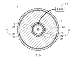
図1は、本発明の第1の実施の形態に係る金属空気電池1を示す縦断面図である。金属空気電池1は略円筒状であり、図1は、金属空気電池1の中心軸J1を含む断面を示す。図2は、金属空気電池1を図1中のA−Aの位置にて切断した横断面図である。図1および図2に示すように、金属空気電池1は、正極2、負極3、電解質層4および空気導入管5を備える二次電池であり、中心軸J1から径方向の外側に向かって、空気導入管5、正極2、電解質層4および負極3の順に同心円状に配置される。換言すれば、金属空気電池1は、外周に負極3が配置され、内周に正極2が配置される略円筒状である。   FIG. 1 is a longitudinal sectional view showing a metal-air battery 1 according to the first embodiment of the present invention. The metal-air battery 1 has a substantially cylindrical shape, and FIG. 1 shows a cross section including the central axis J1 of the metal-air battery 1. FIG. 2 is a cross-sectional view of the metal-air battery 1 cut at the position AA in FIG. As shown in FIGS. 1 and 2, the metal-air battery 1 is a secondary battery that includes a positive electrode 2, a negative electrode 3, an electrolyte layer 4, and an air introduction tube 5, and extends radially outward from the central axis J <b> 1. The air introduction tube 5, the positive electrode 2, the electrolyte layer 4 and the negative electrode 3 are arranged concentrically in this order. In other words, the metal-air battery 1 has a substantially cylindrical shape in which the negative electrode 3 is disposed on the outer periphery and the positive electrode 2 is disposed on the inner periphery.

正極2は、略有底円筒状の多孔質部材であり、それぞれが略有底円筒状の正極支持部21、正極導電層22および正極触媒層23を備える。正極導電層22は正極支持部21の外側面上および外底面上に積層され、正極触媒層23は正極導電層22の外側面上および外底面上に積層される。正極2では、正極導電層22の外側面の一部において、正極触媒層23に代えて正極集電体24が設けられ、図1に示すように、正極集電体24の上端に正極集電端子25が接続される。正極2および正極集電体24には炭素(C)は含まれない。   The positive electrode 2 is a substantially bottomed cylindrical porous member, and includes a substantially bottomed cylindrical positive electrode support 21, a positive electrode conductive layer 22, and a positive electrode catalyst layer 23. The positive electrode conductive layer 22 is stacked on the outer surface and the outer bottom surface of the positive electrode support portion 21, and the positive electrode catalyst layer 23 is stacked on the outer surface and the outer bottom surface of the positive electrode conductive layer 22. In the positive electrode 2, a positive electrode current collector 24 is provided on a part of the outer surface of the positive electrode conductive layer 22 instead of the positive electrode catalyst layer 23, and the positive electrode current collector 24 is disposed at the upper end of the positive electrode current collector 24 as shown in FIG. Terminal 25 is connected. The positive electrode 2 and the positive electrode current collector 24 do not contain carbon (C).

正極支持部21は、アルミナ(酸化アルミニウム:Al)やジルコニア、セラミック、ステンレス鋼等の金属により形成される多孔質部材であり、本実施の形態では、正極支持部21は絶縁体であるアルミナにより形成される。正極支持部21の形成は、押し出し成形、CIP(Cold Isostatic Press:冷間等方圧プレス)および焼成、または、HIP(Hot Isostatic Press:熱間等方圧プレス)等により行われる。 The positive electrode support portion 21 is a porous member formed of a metal such as alumina (aluminum oxide: Al 2 O 3 ), zirconia, ceramic, stainless steel, etc. In this embodiment, the positive electrode support portion 21 is an insulator. It is made of some alumina. The positive electrode support 21 is formed by extrusion molding, CIP (Cold Isostatic Press) and firing, or HIP (Hot Isostatic Press).

正極導電層22は、導電性を有するペロブスカイト型酸化物(通常は粉体状)により主に形成される多孔質の薄い導電膜であり、好ましくは、化学式A1−xBO(0.9≦1−x<1.0)にて表されるペロブスカイト型酸化物により形成される。本実施の形態では、正極導電層22はランタン系のペロブスカイト型酸化物(具体的には、ランタンストロンチウムマンガナイト(LSM:La(Sr)MnO)やランタンストロンチウムコバルタイト(LSC:La(Sr)CoO)等のAサイトにランタンを含むペロブスカイト型酸化物)により形成される。正極導電層22の形成は、スラリーコート法、水熱合成法、CVD(Chemical Vapor Deposition:化学蒸着)またはPVD(Physical Vapor Deposition:物理蒸着)等により行われる。 The positive electrode conductive layer 22 is a porous thin conductive film mainly formed of a conductive perovskite oxide (usually in powder form), and preferably has a chemical formula A 1-x BO 3 (0.9 It is formed of a perovskite oxide represented by ≦ 1-x <1.0). In the present embodiment, the positive electrode conductive layer 22 includes a lanthanum perovskite oxide (specifically, lanthanum strontium manganite (LSM: La (Sr) MnO 3 ) or lanthanum strontium cobaltite (LSC: La (Sr) A perovskite oxide containing lanthanum at the A site such as CoO 3 ). The positive electrode conductive layer 22 is formed by a slurry coating method, a hydrothermal synthesis method, CVD (Chemical Vapor Deposition), PVD (Physical Vapor Deposition), or the like.

正極触媒層23は、酸素還元反応を促進する触媒であるマンガン(Mn)やニッケル(Ni)、コバルト(Co)等の金属酸化物により主に形成される多孔質部材である。正極触媒層23は、白金(Pt)やパラディウム(Pd)、銀(Ag)、ロジウム(Rh)、ルテニウム(Ru)のような貴金属、または、これらの貴金属と上記金属酸化物との混合物により形成されてもよい。本実施の形態では、正極触媒層23はβ型(ルチル型)の結晶構造を有する二酸化マンガン(MnO)により形成される。正極触媒層23の形成は、スラリーコート法および焼成、水熱合成法、CVDまたはPVD等により行われる。 The positive electrode catalyst layer 23 is a porous member mainly formed of a metal oxide such as manganese (Mn), nickel (Ni), or cobalt (Co) that is a catalyst for promoting an oxygen reduction reaction. The positive electrode catalyst layer 23 is formed of a noble metal such as platinum (Pt), palladium (Pd), silver (Ag), rhodium (Rh), ruthenium (Ru), or a mixture of these noble metals and the above metal oxide. May be. In the present embodiment, the positive electrode catalyst layer 23 is formed of manganese dioxide (MnO 2 ) having a β-type (rutile) crystal structure. The positive electrode catalyst layer 23 is formed by a slurry coating method and baking, a hydrothermal synthesis method, CVD, PVD, or the like.

図1および図2に示すように、負極3は、略有底円筒状の負極支持部31、および、負極支持部31の内側面上および内底面上に積層された略有底円筒状の負極導電層32を備える。負極支持部31は、金属等の導電性材料(本実施の形態では、ステンレス鋼)により形成された負極集電体であり、負極支持部31の外側面には、図1に示すように負極集電端子33が設けられる。負極導電層32は、リチウム(Li)や亜鉛(Zn)等の金属、または、当該金属を含む合金により形成された薄い導電膜であり、本実施の形態では、負極導電層32はリチウムまたはリチウム合金により形成される。負極導電層32の形成は、例えば、スラリーコート法により行われる。   As shown in FIGS. 1 and 2, the negative electrode 3 includes a substantially bottomed cylindrical negative electrode support portion 31, and a substantially bottomed cylindrical negative electrode layered on the inner side surface and the inner bottom surface of the negative electrode support portion 31. A conductive layer 32 is provided. The negative electrode support 31 is a negative electrode current collector formed of a conductive material such as metal (stainless steel in the present embodiment). On the outer surface of the negative electrode support 31, as shown in FIG. A current collecting terminal 33 is provided. The negative electrode conductive layer 32 is a thin conductive film formed of a metal such as lithium (Li) or zinc (Zn), or an alloy containing the metal. In this embodiment, the negative electrode conductive layer 32 is lithium or lithium. It is formed from an alloy. The negative electrode conductive layer 32 is formed by, for example, a slurry coating method.

電解質層4は、非水系の電解質により形成され、本実施の形態では、有機溶剤系の電解質溶液が正極2と負極3との間に充填される(配置される)ことにより形成される。電解質層4は、正極2の正極触媒層23、正極集電体24、および、負極3の負極導電層32に接する。電解質層4の上面は、正極支持部21の外側面および負極支持部31の内側面に接する略円環状の中蓋51により閉塞され、中蓋51の上方には、中蓋51と同形状の上蓋52が設けられて略有底円筒状の負極3の上部開口が閉塞される。   The electrolyte layer 4 is formed of a non-aqueous electrolyte. In the present embodiment, the electrolyte layer 4 is formed by filling (disposing) an organic solvent-based electrolyte solution between the positive electrode 2 and the negative electrode 3. The electrolyte layer 4 is in contact with the positive electrode catalyst layer 23 of the positive electrode 2, the positive electrode current collector 24, and the negative electrode conductive layer 32 of the negative electrode 3. The upper surface of the electrolyte layer 4 is closed by a substantially annular inner lid 51 in contact with the outer surface of the positive electrode support portion 21 and the inner surface of the negative electrode support portion 31, and has the same shape as the inner lid 51 above the inner lid 51. An upper lid 52 is provided to close the upper opening of the substantially bottomed cylindrical negative electrode 3.

空気導入管5は、略有底円筒状の正極2の内側に配置され、空気導入管5の下端は正極2の正極支持部21の底部近傍に位置する。空気導入管5の上端は、空気から水分および二酸化炭素を除去する除去部53に接続される。除去部53では、膜分離法または吸着により空気中の水分および二酸化炭素の除去が行われる。除去部53からの空気(すなわち、水分および二酸化炭素が除去された空気)は、空気導入管5により正極2の内側において底部近傍へと導かれ、正極2へと供給されつつ正極2の内側面に沿って上昇して正極2の上部開口から外部へと排出される。金属空気電池1では、空気導入管5が、除去部53からの空気を正極2に供給するガス供給部となる。正極2に供給された空気は、多孔質部材である正極支持部21および正極導電層22を通過して正極触媒層23へと供給される。   The air introduction tube 5 is arranged inside the substantially bottomed cylindrical positive electrode 2, and the lower end of the air introduction tube 5 is located near the bottom of the positive electrode support portion 21 of the positive electrode 2. The upper end of the air introduction pipe 5 is connected to a removal unit 53 that removes moisture and carbon dioxide from the air. The removing unit 53 removes moisture and carbon dioxide in the air by membrane separation or adsorption. Air from the removing unit 53 (that is, air from which moisture and carbon dioxide have been removed) is guided to the vicinity of the bottom inside the positive electrode 2 by the air introduction tube 5 and is supplied to the positive electrode 2 while being supplied to the inner surface of the positive electrode 2. Are discharged from the upper opening of the positive electrode 2 to the outside. In the metal-air battery 1, the air introduction tube 5 serves as a gas supply unit that supplies the air from the removal unit 53 to the positive electrode 2. The air supplied to the positive electrode 2 passes through the positive electrode support portion 21 and the positive electrode conductive layer 22 which are porous members, and is supplied to the positive electrode catalyst layer 23.

金属空気電池1において放電が行われる際には、負極集電端子33と正極集電端子25とが負荷(例えば、照明器具等)を介して電気的に接続される。負極3では、負極導電層32に含まれるリチウムが酸化されてリチウムイオン(Li)が生成され、電子は負極集電端子33、正極集電体24および正極集電端子25を介して正極2に供給される。正極2では、空気導入管5により供給された空気中の酸素が、負極3から供給された電子により還元されて酸素イオン(O2−)が生成される。正極2では、正極触媒層23に含まれる正極触媒により酸素イオンの生成(すなわち、酸素の還元反応)が促進されるため、当該還元反応に消費されるエネルギーによる過電圧が小さくなり、金属空気電池1の放電電圧を高くすることができる。正極2にて生成された酸素イオンは、負極3から電解質層4中に溶解したリチウムイオンと結合し、これにより酸化リチウム(LiO)が生成される。 When discharging is performed in the metal-air battery 1, the negative electrode current collecting terminal 33 and the positive electrode current collecting terminal 25 are electrically connected via a load (for example, a lighting fixture). In the negative electrode 3, lithium contained in the negative electrode conductive layer 32 is oxidized to generate lithium ions (Li + ), and electrons are supplied to the positive electrode 2 through the negative electrode current collector terminal 33, the positive electrode current collector 24, and the positive electrode current collector terminal 25. To be supplied. In the positive electrode 2, oxygen in the air supplied from the air introduction tube 5 is reduced by electrons supplied from the negative electrode 3 to generate oxygen ions (O 2− ). In the positive electrode 2, the generation of oxygen ions (that is, the oxygen reduction reaction) is promoted by the positive electrode catalyst contained in the positive electrode catalyst layer 23, so the overvoltage due to the energy consumed in the reduction reaction is reduced, and the metal-air battery 1. The discharge voltage can be increased. Oxygen ions generated at the positive electrode 2 are combined with lithium ions dissolved in the electrolyte layer 4 from the negative electrode 3, thereby generating lithium oxide (Li 2 O).

一方、金属空気電池1において充電が行われる際には、負極集電端子33と正極集電端子25との間に電圧が付与され、正極2において酸化リチウムが分解されるとともに酸素イオンから正極集電体24を介して正極集電端子25へと電子が供給されて酸素が発生する。負極3では、負極集電端子33に供給される電子によりリチウムイオンが還元されて負極導電層32の表面にリチウムが析出する。正極2では、正極触媒層23に含まれる正極触媒により酸素の発生が促進されるため、過電圧が小さくなり、金属空気電池1の充電電圧を低くすることができる。   On the other hand, when charging is performed in the metal-air battery 1, a voltage is applied between the negative electrode current collector terminal 33 and the positive electrode current collector terminal 25, lithium oxide is decomposed at the positive electrode 2, and positive electrode current is collected from oxygen ions. Electrons are supplied to the positive electrode current collector terminal 25 through the electric body 24 to generate oxygen. In the negative electrode 3, lithium ions are reduced by electrons supplied to the negative electrode current collector terminal 33, and lithium is deposited on the surface of the negative electrode conductive layer 32. In the positive electrode 2, since the generation of oxygen is promoted by the positive electrode catalyst contained in the positive electrode catalyst layer 23, the overvoltage is reduced and the charging voltage of the metal-air battery 1 can be lowered.

ところで、通常の金属空気電池の正極は、導電性を得るための炭素が主体とされ、当該炭素に酸素の還元反応を促進する正極触媒が添加されている。しかしながら、このような金属空気電池では、放電の際に生成されるリチウムイオンが炭酸リチウム (LiCO)として正極上に析出し、充電の際に炭酸リチウムを電気分解してイオン化するために大きなエネルギーが必要であるため、充電電圧が高くなってしまう。 By the way, a positive electrode of a normal metal-air battery is mainly composed of carbon for obtaining conductivity, and a positive electrode catalyst for promoting a reduction reaction of oxygen is added to the carbon. However, in such a metal-air battery, lithium ions generated during discharge are deposited on the positive electrode as lithium carbonate (Li 2 CO 3 ), and the lithium carbonate is electrolyzed and ionized during charging. Since a large amount of energy is required, the charging voltage becomes high.

これに対し、本実施の形態に係る金属空気電池1では、ペロブスカイト型酸化物にて形成された正極導電層22上に正極触媒層23を形成することにより、炭素を含有しない正極2を実現することができる。これにより、放電の際に正極2上に炭酸リチウムが生成されることを防止することができ、金属空気電池1の充電電圧を低くすることができる。また、正極導電層22が、導電性が高いランタン系のペロブスカイト型酸化物を含んでいるため、金属空気電池1の放電電圧を高くすることができる。さらに、正極導電層22に含まれるペロブスカイト型酸化物が化学式A1−xBO(0.9≦1−x<1.0)にて表されるものであることにより、正極導電層22が水分により劣化してしまうことを防止し、金属空気電池1の耐久性を向上することができる。 In contrast, in the metal-air battery 1 according to the present embodiment, the positive electrode 2 containing no carbon is realized by forming the positive electrode catalyst layer 23 on the positive electrode conductive layer 22 formed of a perovskite oxide. be able to. Thereby, it can prevent that lithium carbonate is produced | generated on the positive electrode 2 in the case of discharge, and the charge voltage of the metal air battery 1 can be made low. Further, since the positive electrode conductive layer 22 contains a highly conductive lanthanum perovskite oxide, the discharge voltage of the metal-air battery 1 can be increased. Further, the perovskite oxide contained in the positive electrode conductive layer 22 is represented by the chemical formula A 1-x BO 3 (0.9 ≦ 1-x <1.0), whereby the positive electrode conductive layer 22 It is possible to prevent deterioration due to moisture and improve the durability of the metal-air battery 1.

金属空気電池1では、正極2の正極導電層22が、正極支持部21により支持(担持)される薄い導電膜であるため、比較的高価なペロブスカイト型酸化物の使用量を低減することができる。その結果、金属空気電池1の製造コストを低減することができる。また、負極3が、高い理論電圧および電気化学当量を有するリチウムまたはリチウム合金を含んでいるため、金属空気電池1を高容量化することができる。   In the metal-air battery 1, since the positive electrode conductive layer 22 of the positive electrode 2 is a thin conductive film supported (supported) by the positive electrode support portion 21, it is possible to reduce the amount of relatively expensive perovskite oxide used. . As a result, the manufacturing cost of the metal-air battery 1 can be reduced. Moreover, since the negative electrode 3 contains lithium or a lithium alloy having a high theoretical voltage and an electrochemical equivalent, the capacity of the metal-air battery 1 can be increased.

上述のように、金属空気電池1は、負極3および正極2がそれぞれ外周および内周に配置される円筒状であるため、金属空気電池1の大型化が要求される場合であっても、負極導電層32や正極導電層22のような薄膜状の層を容易に形成することができる。すなわち、金属空気電池1の大型化に容易に対応することができる。また、空気導入管5により、水分および二酸化炭素が除去された空気が正極2に供給されることにより、空気中の二酸化炭素とリチウムイオンとが反応して正極2に炭酸リチウムが付着することが防止されるとともに、負極3の負極導電層32に含まれるリチウムが水分と反応して負極導電層32が劣化してしまうことも防止される。   As described above, since the metal-air battery 1 has a cylindrical shape in which the negative electrode 3 and the positive electrode 2 are disposed on the outer periphery and the inner periphery, respectively, A thin film layer such as the conductive layer 32 and the positive electrode conductive layer 22 can be easily formed. That is, it is possible to easily cope with an increase in size of the metal-air battery 1. In addition, when air from which moisture and carbon dioxide have been removed is supplied to the positive electrode 2 through the air introduction tube 5, carbon dioxide in the air reacts with lithium ions, and lithium carbonate adheres to the positive electrode 2. In addition to being prevented, lithium contained in the negative electrode conductive layer 32 of the negative electrode 3 is prevented from reacting with moisture and deteriorating the negative electrode conductive layer 32.

金属空気電池1では、電解質層4の非水系電解質溶液に無機微粒子(フィラー)が添加されてもよい。無機微粒子としては、アルミナや二酸化ケイ素(SiO)、二酸化チタン(TiO)、ゼオライト、ペロブスカイト型酸化物等の無機酸化物が好ましく、特に、Si比が高い(例えば、Si/Alが2以上の)ゼオライト粒子がより好ましい。電解質層4の電解質溶液が無機微粒子を含むことにより、金属空気電池1の内部抵抗が低減して電池容量が増大するとともに、金属空気電池1からの漏液が防止される。なお、以下の実施の形態に係る金属空気電池においても、後述する第1電解質層4に含まれる非水系の電解質溶液が無機微粒子を含むことにより、上記と同様の効果(すなわち、電池容量の増大および漏液防止)を得ることができる。 In the metal-air battery 1, inorganic fine particles (filler) may be added to the non-aqueous electrolyte solution of the electrolyte layer 4. As the inorganic fine particles, inorganic oxides such as alumina, silicon dioxide (SiO 2 ), titanium dioxide (TiO 2 ), zeolite, and perovskite oxide are preferable, and the Si ratio is particularly high (for example, Si / Al is 2 or more). Zeolite particles are preferred. When the electrolyte solution of the electrolyte layer 4 contains inorganic fine particles, the internal resistance of the metal-air battery 1 is reduced and the battery capacity is increased, and leakage from the metal-air battery 1 is prevented. Even in the metal-air battery according to the following embodiment, the non-aqueous electrolyte solution contained in the first electrolyte layer 4 described later contains inorganic fine particles, so that the same effect as described above (that is, an increase in battery capacity) And prevention of leakage).

次に、本発明の第2の実施の形態に係る金属空気電池について説明する。図3および図4は、第2の実施の形態に係る金属空気電池1aの縦断面図および横断面図であり、図4は、金属空気電池1aを図3中のB−Bの位置にて切断した図である。図3および図4では、図を簡素化するために、除去部53の図示を省略している(図5ないし図7においても同様)。   Next, a metal air battery according to a second embodiment of the present invention will be described. 3 and 4 are a longitudinal sectional view and a transverse sectional view of the metal-air battery 1a according to the second embodiment, and FIG. 4 shows the metal-air battery 1a at the position BB in FIG. It is the figure which cut | disconnected. 3 and 4, the illustration of the removal unit 53 is omitted to simplify the drawing (the same applies to FIGS. 5 to 7).

金属空気電池1aでは、電解質層4と正極2との間にもう1つの電解質層6が配置され、電解質層4と電解質層6との間に隔壁層7が配置される。隔壁層7は、薄膜状の固体電解質であり、リチウムイオンのみを選択的に通過させる。その他の構成は、図1および図2に示す金属空気電池1と同様であり、以下の説明では、対応する構成に同符号を付す。また、2つの電解質層4,6を区別するために、電解質層4および電解質層6をそれぞれ、「第1電解質層4」および「第2電解質層6」という。   In the metal-air battery 1 a, another electrolyte layer 6 is disposed between the electrolyte layer 4 and the positive electrode 2, and a partition wall layer 7 is disposed between the electrolyte layer 4 and the electrolyte layer 6. The partition layer 7 is a thin-film solid electrolyte, and selectively allows only lithium ions to pass therethrough. Other configurations are the same as those of the metal-air battery 1 shown in FIGS. 1 and 2, and in the following description, the same reference numerals are given to the corresponding configurations. Further, in order to distinguish between the two electrolyte layers 4 and 6, the electrolyte layer 4 and the electrolyte layer 6 are referred to as “first electrolyte layer 4” and “second electrolyte layer 6”, respectively.

図3および図4に示すように、第2電解質層6は、中心軸J1を中心とする略有底円筒状であり、正極2に接する。隔壁層7も略有底円筒状であり、第1電解質層4および第2電解質層6に接する。第2電解質層6は、水系の電解質溶液が正極2と隔壁層7との間に充填される(配置される)ことにより形成される。第2電解質層6の上面は、第1電解質層4の上面と同様に、略円環状の中蓋51(図3のみに図示する。)により閉塞される。本実施の形態では、第1電解質層4は、非水系(例えば、有機溶剤系)の電解質溶液を含浸させた多孔質ポリマであり、薄膜状の固体電解質である隔壁層7は、第1電解質層4の内側面上および内底面上にて第1電解質層4により支持(担持)される。すなわち、第1電解質層4は、隔壁層7を支持する隔壁支持層でもある。また、隔壁層7としては、化学式Lil+x+yTi2−xAl3−ySi12 にて表されるガラスセラミックス(LTAP)が利用される。 As shown in FIGS. 3 and 4, the second electrolyte layer 6 has a substantially bottomed cylindrical shape centered on the central axis J <b> 1 and is in contact with the positive electrode 2. The partition wall layer 7 also has a substantially bottomed cylindrical shape and is in contact with the first electrolyte layer 4 and the second electrolyte layer 6. The second electrolyte layer 6 is formed by filling (arranging) an aqueous electrolyte solution between the positive electrode 2 and the partition wall layer 7. Similar to the top surface of the first electrolyte layer 4, the top surface of the second electrolyte layer 6 is closed by a substantially annular inner lid 51 (shown only in FIG. 3). In the present embodiment, the first electrolyte layer 4 is a porous polymer impregnated with a non-aqueous (eg, organic solvent-based) electrolyte solution, and the partition layer 7 that is a thin-film solid electrolyte is the first electrolyte layer. The first electrolyte layer 4 supports (supports) the inner surface and the inner bottom surface of the layer 4. That is, the first electrolyte layer 4 is also a partition support layer that supports the partition layer 7. Further, as the partition wall layer 7, glass ceramics (LTAP) represented by the chemical formula Li 1 + x + y Ti 2−x Al x P 3−y Si y O 12 is used.

金属空気電池1aにおいて放電が行われる際には、負極3の負極導電層32に含まれるリチウムが酸化されてリチウムイオンが生成され、電子は負極集電端子33、正極集電体24および正極集電端子25を介して正極2に供給される。負極集電端子33および正極集電端子25は図3のみに図示される。正極2では、空気導入管5により供給された空気中の酸素が、負極3から供給された電子により還元されて酸素イオンが生成され、酸素イオンが第2電解質層6に含まれる水と反応して水酸化物イオン(OH)が生成される。水酸化物イオンは、負極3から電解質層4中に溶解したリチウムイオンと共に水酸化リチウム(LiOH)となる。水酸化リチウムは水溶性であるため、第2電解質層6の水系電解質溶液に溶ける。 When discharging is performed in the metal-air battery 1a, lithium contained in the negative electrode conductive layer 32 of the negative electrode 3 is oxidized to generate lithium ions, and electrons are collected in the negative electrode current collector terminal 33, the positive electrode current collector 24, and the positive electrode current collector. It is supplied to the positive electrode 2 through the electric terminal 25. The negative electrode current collecting terminal 33 and the positive electrode current collecting terminal 25 are illustrated only in FIG. In the positive electrode 2, oxygen in the air supplied from the air introduction tube 5 is reduced by electrons supplied from the negative electrode 3 to generate oxygen ions, and the oxygen ions react with water contained in the second electrolyte layer 6. Thus, hydroxide ions (OH ) are generated. The hydroxide ions become lithium hydroxide (LiOH) together with the lithium ions dissolved in the electrolyte layer 4 from the negative electrode 3. Since lithium hydroxide is water-soluble, it dissolves in the aqueous electrolyte solution of the second electrolyte layer 6.

金属空気電池1aにおいて充電が行われる際には、負極集電端子33と正極集電端子25との間に電圧が付与され、正極2において水酸化物イオンから正極集電端子25へと電子が供給されて水と酸素が発生する。負極3では、負極集電端子33に供給される電子によりリチウムイオンが還元されて負極導電層32の表面にリチウムが析出する。   When charging is performed in the metal-air battery 1a, a voltage is applied between the negative electrode current collector terminal 33 and the positive electrode current collector terminal 25, and electrons are transferred from the hydroxide ions to the positive electrode current collector terminal 25 in the positive electrode 2. Supplying water and oxygen. In the negative electrode 3, lithium ions are reduced by electrons supplied to the negative electrode current collector terminal 33, and lithium is deposited on the surface of the negative electrode conductive layer 32.

金属空気電池1aでは、第1の実施の形態と同様に、正極2が炭素を含有しないため、放電の際に正極2上に炭酸リチウムが生成されることを防止することができ、金属空気電池1aの充電電圧を低くすることができる。金属空気電池1aでは、特に、正極2と負極3との間に隔壁層7を設けることにより、充電の際に負極3上においてリチウムが樹枝状に析出した場合に、樹枝状に析出した部位(いわゆる、デンドライト)の正極2に向けての成長を抑制することができる。その結果、デンドライトが正極2に到達して短絡が発生することを防止することができる。また、第1電解質層4により隔壁層7を支持することにより、薄膜状の隔壁層7の設置を容易とし、その結果、金属空気電池1aの小型化が実現される。さらに、隔壁層7が薄膜状であるため、隔壁層7を厚くする場合に比べてイオン導電率が増大される。   In the metal-air battery 1a, as in the first embodiment, since the positive electrode 2 does not contain carbon, it is possible to prevent lithium carbonate from being generated on the positive electrode 2 during discharge. The charging voltage of 1a can be lowered. In the metal-air battery 1a, in particular, by providing the partition layer 7 between the positive electrode 2 and the negative electrode 3, when lithium is deposited in a dendritic shape on the negative electrode 3 during charging, the portion (in a dendritic shape) ( The growth of so-called dendrites toward the positive electrode 2 can be suppressed. As a result, it is possible to prevent the dendrite from reaching the positive electrode 2 and causing a short circuit. Further, by supporting the partition wall layer 7 by the first electrolyte layer 4, the thin film partition wall layer 7 can be easily installed, and as a result, the metal-air battery 1a can be downsized. Furthermore, since the partition wall layer 7 is thin, the ionic conductivity is increased as compared with the case where the partition wall layer 7 is thickened.

次に、本発明の第3の実施の形態に係る金属空気電池について説明する。図5は、第3の実施の形態に係る金属空気電池1bの横断面図である。金属空気電池1bでは、図3および図4に示す金属空気電池1aの隔壁層7(固体電解質)に代えて、セパレータである隔壁層7aが設けられる。その他の構成は、図3および図4に示す金属空気電池1aと同様であり、以下の説明では、対応する構成に同符号を付す。   Next, a metal air battery according to a third embodiment of the present invention will be described. FIG. 5 is a cross-sectional view of a metal-air battery 1b according to the third embodiment. In the metal-air battery 1b, a partition wall layer 7a as a separator is provided instead of the partition layer 7 (solid electrolyte) of the metal-air battery 1a shown in FIGS. Other configurations are the same as those of the metal-air battery 1a shown in FIGS. 3 and 4, and in the following description, the corresponding components are denoted by the same reference numerals.

隔壁層7aは、セラミックや金属、無機材料または有機材料等により形成された多孔質部材であり、リチウムイオンを選択的に通過させる電解質を孔内に保持する。隔壁層7aの形成は、押し出し成形、CIPおよび焼成、または、HIP等により行われる。金属空気電池1bにおける放電および充電の際の反応は、第2の実施の形態に係る金属空気電池1aと同様である。   The partition layer 7a is a porous member formed of ceramic, metal, inorganic material, organic material, or the like, and holds an electrolyte that selectively allows lithium ions to pass through in the pores. The partition wall layer 7a is formed by extrusion molding, CIP and baking, HIP, or the like. The reaction in discharging and charging in the metal-air battery 1b is the same as that in the metal-air battery 1a according to the second embodiment.

金属空気電池1bでは、第1および第2の実施の形態と同様に、正極2が炭素を含有しないため、放電の際に正極2上に炭酸リチウムが生成されることを防止することができ、金属空気電池1bの充電電圧を低くすることができる。また、正極2と負極3との間に隔壁層7aを設けることにより、第2の実施の形態と同様に、充電の際における負極3上のデンドライトの成長を抑制し、短絡が発生することを防止することができる。金属空気電池1bでは、特に、セパレータである隔壁層7aの設置に第1電解質層4による支持が必要ないため、第1電解質層4の材料選択の自由度が向上される。   In the metal-air battery 1b, as in the first and second embodiments, since the positive electrode 2 does not contain carbon, it is possible to prevent lithium carbonate from being generated on the positive electrode 2 during discharge, The charging voltage of the metal-air battery 1b can be lowered. Further, by providing the partition layer 7a between the positive electrode 2 and the negative electrode 3, as in the second embodiment, the growth of dendrites on the negative electrode 3 during charging is suppressed and a short circuit occurs. Can be prevented. In the metal-air battery 1b, in particular, the support by the first electrolyte layer 4 is not necessary for the installation of the partition wall layer 7a, which is a separator. Therefore, the degree of freedom in selecting the material of the first electrolyte layer 4 is improved.

次に、本発明の第4の実施の形態に係る金属空気電池について説明する。図6は、第4の実施の形態に係る金属空気電池1cの横断面図である。金属空気電池1cは、第2電解質層6と隔壁層7との間に隔壁支持層71を備える点を除き、図3および図4に示す金属空気電池1aと同様の構成を有し、以下の説明では、対応する構成に同符号を付す。   Next, a metal air battery according to a fourth embodiment of the present invention will be described. FIG. 6 is a cross-sectional view of a metal-air battery 1c according to the fourth embodiment. The metal-air battery 1c has the same configuration as that of the metal-air battery 1a shown in FIGS. 3 and 4 except that a partition support layer 71 is provided between the second electrolyte layer 6 and the partition layer 7, and includes the following: In the description, the same reference numerals are assigned to the corresponding components.

隔壁支持層71は、セラミックや金属、無機材料または有機材料等により、押し出し成形、CIPおよび焼成、または、HIP等の方法で形成された多孔質部材であり、孔内に第2電解質層6の水系の電解質溶液が含浸する。薄膜状の固体電解質である隔壁層7は、隔壁支持層71の外側面上および外底面上にて隔壁支持層71により支持(担持)される。金属空気電池1cにおける放電および充電の際の反応は、第2の実施の形態に係る金属空気電池1aと同様である。   The partition support layer 71 is a porous member formed by a method such as extrusion, CIP and firing, or HIP using ceramic, metal, inorganic material or organic material, and the second electrolyte layer 6 is formed in the hole. The aqueous electrolyte solution is impregnated. The partition wall layer 7, which is a thin-film solid electrolyte, is supported (supported) by the partition wall support layer 71 on the outer surface and the outer bottom surface of the partition wall support layer 71. Reactions in discharging and charging in the metal-air battery 1c are the same as those in the metal-air battery 1a according to the second embodiment.

金属空気電池1cでは、第1ないし第3の実施の形態と同様に、正極2が炭素を含有しないため、放電の際に正極2上に炭酸リチウムが生成されることを防止することができ、金属空気電池1cの充電電圧を低くすることができる。また、正極2と負極3との間に隔壁層7および隔壁支持層71を設けることにより、第2の実施の形態と同様に、充電の際における負極3上のデンドライトの成長を抑制し、短絡が発生することを防止することができる。上述のように、金属空気電池1cでは、隔壁層7が隔壁支持層71により支持されており、第1電解質層4による隔壁層7の支持が必要ないため、第1電解質層4の材料選択の自由度が向上される。   In the metal-air battery 1c, as in the first to third embodiments, since the positive electrode 2 does not contain carbon, it is possible to prevent lithium carbonate from being generated on the positive electrode 2 during discharge, The charging voltage of the metal-air battery 1c can be lowered. Further, by providing the partition wall layer 7 and the partition support layer 71 between the positive electrode 2 and the negative electrode 3, as in the second embodiment, the growth of dendrites on the negative electrode 3 during charging is suppressed and a short circuit occurs. Can be prevented. As described above, in the metal-air battery 1c, the partition layer 7 is supported by the partition support layer 71, and it is not necessary to support the partition layer 7 by the first electrolyte layer 4. Therefore, the material selection of the first electrolyte layer 4 is not necessary. The degree of freedom is improved.

次に、本発明の第5の実施の形態に係る金属空気電池について説明する。図7は、第5の実施の形態に係る金属空気電池1dの縦断面図である。金属空気電池1dは、第1電解質層4が、第1電解質層4の非水系の電解質溶液を循環させる循環機構81に接続される点、および、第2電解質層6が、第2電解質層6の水系の電解質溶液を交換する交換機構に接続される点を除き、図6に示す金属空気電池1cと同様の構成を有し、以下の説明では、対応する構成に同符号を付す。   Next, a metal air battery according to a fifth embodiment of the present invention will be described. FIG. 7 is a longitudinal sectional view of a metal-air battery 1d according to the fifth embodiment. In the metal-air battery 1d, the first electrolyte layer 4 is connected to a circulation mechanism 81 that circulates the non-aqueous electrolyte solution of the first electrolyte layer 4, and the second electrolyte layer 6 is connected to the second electrolyte layer 6. The metal-air battery 1c shown in FIG. 6 has the same configuration except that it is connected to an exchange mechanism for exchanging the aqueous electrolyte solution. In the following description, the same reference numerals are given to the corresponding configurations.

図7に示すように、金属空気電池1dの側部には、第1電解質層4に電解質溶液を供給する供給口41、および、第1電解質層4の電解質溶液が排出される排出口42が形成される。供給口41および排出口42は管路43を介して循環機構81に接続され、排出口42から排出された電解質溶液は、循環機構81を介して供給口41から第1電解質層4に再度供給される。これにより、第1電解質層4内に電解質溶液の流れが生じ、金属空気電池1dの充電時におけるデンドライトの発生や成長が抑制される。また、循環機構81にはフィルターが設けられており、充電時等に負極導電層32からリチウムの薄片が剥落した場合等、当該リチウムが循環機構81において回収される。   As shown in FIG. 7, a supply port 41 for supplying the electrolyte solution to the first electrolyte layer 4 and a discharge port 42 for discharging the electrolyte solution of the first electrolyte layer 4 are provided at the side of the metal-air battery 1d. It is formed. The supply port 41 and the discharge port 42 are connected to the circulation mechanism 81 through the conduit 43, and the electrolyte solution discharged from the discharge port 42 is supplied again from the supply port 41 to the first electrolyte layer 4 through the circulation mechanism 81. Is done. Thereby, the flow of the electrolyte solution is generated in the first electrolyte layer 4, and the generation and growth of dendrite during the charging of the metal-air battery 1d is suppressed. Further, the circulation mechanism 81 is provided with a filter, and the lithium is collected in the circulation mechanism 81 when a thin piece of lithium is peeled off from the negative electrode conductive layer 32 during charging or the like.

金属空気電池1dには、第2電解質層6に電解質溶液を供給する供給口61、および、第2電解質層6の電解質溶液が排出される排出口62が形成される。供給口61は上記交換機構の供給機構821に接続され、供給機構821から新たな電解質溶液が第2電解質層6に供給される。排出口62は交換機構の回収機構822に接続され、第2電解質層6から排出された電解質溶液が回収機構822に回収される。これにより、金属空気電池1dの放電時に、第2電解質層6の電解質溶液が水酸化リチウムにより飽和することが防止され、金属空気電池1dの放電時間を増大させることができる。回収機構822により回収された電解質溶液からはリチウムが回収される。当該リチウムは、金属空気電池の負極導電層32として再利用されてもよい。   In the metal-air battery 1d, a supply port 61 for supplying an electrolyte solution to the second electrolyte layer 6 and a discharge port 62 for discharging the electrolyte solution of the second electrolyte layer 6 are formed. The supply port 61 is connected to the supply mechanism 821 of the exchange mechanism, and a new electrolyte solution is supplied from the supply mechanism 821 to the second electrolyte layer 6. The discharge port 62 is connected to the recovery mechanism 822 of the exchange mechanism, and the electrolyte solution discharged from the second electrolyte layer 6 is recovered by the recovery mechanism 822. This prevents the electrolyte solution of the second electrolyte layer 6 from being saturated with lithium hydroxide during the discharge of the metal-air battery 1d, and can increase the discharge time of the metal-air battery 1d. Lithium is recovered from the electrolyte solution recovered by the recovery mechanism 822. The lithium may be reused as the negative electrode conductive layer 32 of the metal-air battery.

以上、本発明の実施の形態について説明してきたが、本発明は上記実施の形態に限定されるものではなく、様々な変更が可能である。   As mentioned above, although embodiment of this invention has been described, this invention is not limited to the said embodiment, A various change is possible.

負極3では、負極支持部31は、必ずしも導電性材料により形成される必要はなく、負極支持部31が絶縁体により形成される場合には、負極集電端子33は、負極支持部31を貫通して負極導電層32に電気的に接続される。また、必ずしも負極支持部31は設けられる必要はなく、リチウムやリチウム合金により負極3全体が形成されてもよい。負極導電層32は、放電の際に酸化されて金属イオンを生成する金属を含む様々な材料により形成されていればよい。   In the negative electrode 3, the negative electrode support portion 31 is not necessarily formed of a conductive material. When the negative electrode support portion 31 is formed of an insulator, the negative electrode current collector terminal 33 penetrates the negative electrode support portion 31. Thus, the negative electrode conductive layer 32 is electrically connected. The negative electrode support 31 is not necessarily provided, and the entire negative electrode 3 may be formed of lithium or a lithium alloy. The negative electrode conductive layer 32 may be formed of various materials including a metal that is oxidized during discharge to generate metal ions.

正極2では、正極支持部21が導電性材料により形成されている場合、正極集電体24が省略されて正極支持部21の内側面に正極集電端子25が設けられてよい。また、正極導電層22がある程度の厚さを有している場合、正極導電層22を支持する正極支持部21は省略されてもよい。この場合、正極集電端子25は正極導電層22の内側面に設けられる。   In the positive electrode 2, when the positive electrode support portion 21 is formed of a conductive material, the positive electrode current collector 24 may be omitted and the positive electrode current collector terminal 25 may be provided on the inner surface of the positive electrode support portion 21. When the positive electrode conductive layer 22 has a certain thickness, the positive electrode support portion 21 that supports the positive electrode conductive layer 22 may be omitted. In this case, the positive electrode current collecting terminal 25 is provided on the inner surface of the positive electrode conductive layer 22.

金属空気電池では、正極支持部21の材料と正極導電層22の材料(すなわち、ペロブスカイト型酸化物)とが混合されたものから導電層が形成され、当該導電層上に正極触媒層23が形成されて正極2とされてもよい。また、正極支持部21、正極導電層22および正極触媒層23の各材料が混合されたものから正極2が形成されてもよい。いずれの場合であっても、正極2が、導電性を有するペロブスカイト型酸化物、および、酸素還元反応を促進する触媒を含むとともに炭素を含んでいないため、金属空気電池の放電の際に、負極3に含まれる金属の炭酸塩が正極2上に生成されることを防止することができる。   In the metal-air battery, a conductive layer is formed from a mixture of the material of the positive electrode support portion 21 and the material of the positive electrode conductive layer 22 (that is, a perovskite oxide), and the positive electrode catalyst layer 23 is formed on the conductive layer. And may be the positive electrode 2. Alternatively, the positive electrode 2 may be formed from a mixture of the positive electrode support portion 21, the positive electrode conductive layer 22, and the positive electrode catalyst layer 23. In any case, since the positive electrode 2 contains a conductive perovskite oxide and a catalyst that promotes an oxygen reduction reaction and does not contain carbon, the negative electrode is discharged during discharge of a metal-air battery. 3 is prevented from being produced on the positive electrode 2.

第1の実施の形態に係る金属空気電池1では、電解質層4は、非水系の電解質により形成されていればよく、例えば、固体電解質により形成されてもよい。電解質層4が固体電解質により形成される場合、デンドライトの発生および成長は抑制される。また、第2ないし第4の実施の形態に係る金属空気電池では、第2電解質層6が非水系の電解質(例えば、非水系の電解質溶液や固体電解質)により形成されてもよい。第2電解質層6が非水系の電解質溶液により形成される場合、当該電解質溶液に上述の無機微粒子(フィラー)が添加されてもよく、電解質溶液が無機微粒子を含むことにより、金属空気電池の内部抵抗が低減して電池容量が増大するとともに、金属空気電池からの漏液が防止される。   In the metal-air battery 1 according to the first embodiment, the electrolyte layer 4 may be formed of a nonaqueous electrolyte, for example, a solid electrolyte. When the electrolyte layer 4 is formed of a solid electrolyte, the generation and growth of dendrites are suppressed. In the metal-air battery according to the second to fourth embodiments, the second electrolyte layer 6 may be formed of a non-aqueous electrolyte (for example, a non-aqueous electrolyte solution or a solid electrolyte). When the second electrolyte layer 6 is formed of a non-aqueous electrolyte solution, the above-described inorganic fine particles (filler) may be added to the electrolyte solution, and the electrolyte solution contains inorganic fine particles, so that the inside of the metal-air battery The resistance is reduced and the battery capacity is increased, and leakage from the metal-air battery is prevented.

上述の金属空気電池の構造は、円筒状以外の形状(例えば、平板状)の金属空気電池に適用されてもよい。また、上記実施の形態では、二次電池について説明したが、上述の金属空気電池の構造は、一次電池や燃料電池に適用されてもよい。   The structure of the metal-air battery described above may be applied to a metal-air battery having a shape other than a cylindrical shape (for example, a flat plate shape). Moreover, in the said embodiment, although the secondary battery was demonstrated, the structure of the above-mentioned metal air battery may be applied to a primary battery or a fuel cell.

1,1a〜1d 金属空気電池
2 正極
3 負極
4 (第1)電解質層
5 空気導入管
6 第2電解質層
7,7a 隔壁層
21 正極支持部
22 正極導電層
23 正極触媒層
81 循環機構
DESCRIPTION OF SYMBOLS 1,1a-1d Metal-air battery 2 Positive electrode 3 Negative electrode 4 (1st) Electrolyte layer 5 Air introduction pipe 6 2nd electrolyte layer 7, 7a Partition layer 21 Positive electrode support part 22 Positive electrode conductive layer 23 Positive electrode catalyst layer 81 Circulation mechanism

Claims (10)

金属空気電池であって、
金属を含むとともに放電の際に金属イオンを生成する負極と、
導電性を有するペロブスカイト型酸化物、および、酸素還元反応を促進する触媒を含むとともに炭素を含まず、放電の際に酸素イオンを生成する多孔質の正極と、
前記負極と前記正極との間に配置されて前記負極に接する非水系の電解質層と、
を備えることを特徴とする金属空気電池。
A metal-air battery,
A negative electrode containing metal and generating metal ions during discharge;
A perovskite oxide having conductivity, and a porous positive electrode that contains a catalyst that promotes an oxygen reduction reaction and does not contain carbon, and generates oxygen ions during discharge;
A non-aqueous electrolyte layer disposed between the negative electrode and the positive electrode and in contact with the negative electrode;
A metal-air battery comprising:
請求項1に記載の金属空気電池であって、
前記正極が、ランタン系の前記ペロブスカイト型酸化物含むことを特徴とする金属空気電池。
The metal-air battery according to claim 1,
The metal-air battery, wherein the positive electrode contains the lanthanum-based perovskite oxide.
請求項1または2に記載の金属空気電池であって、
前記負極に含まれる前記金属がリチウムであることを特徴とする金属空気電池。
The metal-air battery according to claim 1 or 2,
The metal-air battery, wherein the metal contained in the negative electrode is lithium.
請求項1ないし3のいずれかに記載の金属空気電池であって、
前記正極が、
支持部と、
前記支持部上に前記ペロブスカイト型酸化物にて形成された導電膜と、
前記導電膜上に前記触媒により形成された触媒層と、
を備えることを特徴とする金属空気電池。
The metal-air battery according to any one of claims 1 to 3,
The positive electrode is
A support part;
A conductive film formed of the perovskite oxide on the support;
A catalyst layer formed by the catalyst on the conductive film;
A metal-air battery comprising:
請求項1ないし4のいずれかに記載の金属空気電池であって、
前記電解質層と前記正極との間に配置されて前記正極に接するもう1つの電解質層と、
前記電解質層と前記もう1つの電解質層との間に配置されて前記電解質層および前記もう1つの電解質層に接する固体電解質またはセパレータである隔壁層と、
をさらに備えることを特徴とする金属空気電池。
The metal-air battery according to any one of claims 1 to 4,
Another electrolyte layer disposed between the electrolyte layer and the positive electrode and in contact with the positive electrode;
A partition layer disposed between the electrolyte layer and the another electrolyte layer and being a solid electrolyte or separator in contact with the electrolyte layer and the other electrolyte layer;
A metal-air battery, further comprising:
請求項5に記載の金属空気電池であって、
前記隔壁層が膜状の固体電解質であり、
前記電解質層が、非水系の電解質溶液を含浸させた多孔質ポリマであり、前記隔壁層を支持することを特徴とする金属空気電池。
The metal-air battery according to claim 5,
The partition layer is a membrane-shaped solid electrolyte,
The metal-air battery, wherein the electrolyte layer is a porous polymer impregnated with a non-aqueous electrolyte solution and supports the partition wall layer.
請求項1ないし6のいずれかに記載の金属空気電池であって、
外周に前記負極が配置され、内周に前記正極が配置される円筒状であることを特徴とする金属空気電池。
The metal-air battery according to any one of claims 1 to 6,
A metal-air battery, characterized in that the negative electrode is disposed on the outer periphery and the positive electrode is disposed on the inner periphery.
請求項1ないし7のいずれかに記載の金属空気電池であって、
前記電解質層が電解質溶液により形成されており、前記電解質溶液が無機微粒子を含むことを特徴とする金属空気電池。
The metal-air battery according to any one of claims 1 to 7,
The metal-air battery, wherein the electrolyte layer is formed of an electrolyte solution, and the electrolyte solution contains inorganic fine particles.
請求項1ないし8のいずれかに記載の金属空気電池であって、
前記電解質層が電解質溶液により形成されており、前記電解質層が前記電解質溶液を循環させる機構に接続されることを特徴とする金属空気電池。
The metal-air battery according to any one of claims 1 to 8,
The metal-air battery, wherein the electrolyte layer is formed of an electrolyte solution, and the electrolyte layer is connected to a mechanism for circulating the electrolyte solution.
請求項1ないし9のいずれかに記載の金属空気電池であって、
水分および二酸化炭素が除去された空気を前記正極に供給するガス供給部をさらに備えることを特徴とする金属空気電池。
The metal-air battery according to any one of claims 1 to 9,
A metal-air battery, further comprising a gas supply unit that supplies air from which moisture and carbon dioxide have been removed to the positive electrode.
JP2010128796A 2010-06-04 2010-06-04 Metal-air battery Pending JP2011253789A (en)

Priority Applications (6)

Application Number Priority Date Filing Date Title
JP2010128796A JP2011253789A (en) 2010-06-04 2010-06-04 Metal-air battery
US13/700,253 US20130078535A1 (en) 2010-06-04 2011-06-01 Metal-air battery
KR1020127031693A KR20130112697A (en) 2010-06-04 2011-06-01 Metal air battery
CN2011800274665A CN102934280A (en) 2010-06-04 2011-06-01 Metal air battery
PCT/JP2011/062616 WO2011152464A1 (en) 2010-06-04 2011-06-01 Metal air battery
US13/934,510 US20130295472A1 (en) 2010-06-04 2013-07-03 Metal-air battery

Applications Claiming Priority (1)

Application Number Priority Date Filing Date Title
JP2010128796A JP2011253789A (en) 2010-06-04 2010-06-04 Metal-air battery

Publications (2)

Publication Number Publication Date
JP2011253789A true JP2011253789A (en) 2011-12-15
JP2011253789A5 JP2011253789A5 (en) 2013-08-29

Family

ID=45417551

Family Applications (1)

Application Number Title Priority Date Filing Date
JP2010128796A Pending JP2011253789A (en) 2010-06-04 2010-06-04 Metal-air battery

Country Status (1)

Country Link
JP (1) JP2011253789A (en)

Cited By (13)

* Cited by examiner, † Cited by third party
Publication number Priority date Publication date Assignee Title
KR20130112314A (en) * 2012-04-03 2013-10-14 삼성전자주식회사 Lithium air battery module
WO2014156763A1 (en) * 2013-03-29 2014-10-02 日立造船株式会社 Metal-air battery
JP2014194892A (en) * 2013-03-29 2014-10-09 Hitachi Zosen Corp Secondary battery
JP2014194898A (en) * 2013-03-29 2014-10-09 Hitachi Zosen Corp Electrode and secondary battery
JP2015188870A (en) * 2014-03-28 2015-11-02 日立造船株式会社 Manganese dioxide carrying method, porous ceramic member, and metal-air secondary battery
WO2015165708A3 (en) * 2014-04-29 2015-12-23 Mahle International Gmbh Metal-air battery
JP2016037400A (en) * 2014-08-05 2016-03-22 日立造船株式会社 Manufacturing method of perovskite type manganese oxide, film formation method of perovskite type manganese oxide and metal air secondary battery
JP2016157584A (en) * 2015-02-24 2016-09-01 日本電信電話株式会社 Lithium air secondary battery
JP2017515273A (en) * 2014-04-29 2017-06-08 マーレ インターナショナル ゲゼルシャフト ミット ベシュレンクテル ハフツングMAHLE International GmbH Air battery
JP2017174770A (en) * 2016-03-25 2017-09-28 株式会社日本触媒 Metal air battery
WO2019074538A1 (en) * 2017-10-09 2019-04-18 Lawrence Livermore National Security, Llc Three-dimensional rechargeable battery with solid-state electrolyte
WO2021111495A1 (en) * 2019-12-02 2021-06-10 日本電信電話株式会社 Air battery, and method for producing positive electrode of air battery
JPWO2021187356A1 (en) * 2020-03-19 2021-09-23

Citations (8)

* Cited by examiner, † Cited by third party
Publication number Priority date Publication date Assignee Title
JPH0417259A (en) * 1990-05-10 1992-01-22 Matsushita Electric Ind Co Ltd Battery
JPH06124734A (en) * 1992-10-09 1994-05-06 Hitachi Maxell Ltd Oxygen catalytic electrode and air cell using the electrode
JPH0950828A (en) * 1995-08-04 1997-02-18 Matsushita Electric Ind Co Ltd Rectangular air cell
JP2006147442A (en) * 2004-11-24 2006-06-08 Matsushita Electric Ind Co Ltd Aluminum air cell
JP2008066202A (en) * 2006-09-08 2008-03-21 National Institute Of Advanced Industrial & Technology Air battery
JP2008300346A (en) * 2007-05-01 2008-12-11 Toyota Motor Corp Air cell system
JP2009230981A (en) * 2008-03-21 2009-10-08 Toyota Central R&D Labs Inc Nonaqueous metal air battery
JP2011009163A (en) * 2009-06-29 2011-01-13 Sharp Corp Metal-air battery module, and metal-air battery stack

Patent Citations (8)

* Cited by examiner, † Cited by third party
Publication number Priority date Publication date Assignee Title
JPH0417259A (en) * 1990-05-10 1992-01-22 Matsushita Electric Ind Co Ltd Battery
JPH06124734A (en) * 1992-10-09 1994-05-06 Hitachi Maxell Ltd Oxygen catalytic electrode and air cell using the electrode
JPH0950828A (en) * 1995-08-04 1997-02-18 Matsushita Electric Ind Co Ltd Rectangular air cell
JP2006147442A (en) * 2004-11-24 2006-06-08 Matsushita Electric Ind Co Ltd Aluminum air cell
JP2008066202A (en) * 2006-09-08 2008-03-21 National Institute Of Advanced Industrial & Technology Air battery
JP2008300346A (en) * 2007-05-01 2008-12-11 Toyota Motor Corp Air cell system
JP2009230981A (en) * 2008-03-21 2009-10-08 Toyota Central R&D Labs Inc Nonaqueous metal air battery
JP2011009163A (en) * 2009-06-29 2011-01-13 Sharp Corp Metal-air battery module, and metal-air battery stack

Cited By (21)

* Cited by examiner, † Cited by third party
Publication number Priority date Publication date Assignee Title
KR102032245B1 (en) * 2012-04-03 2019-10-16 삼성전자주식회사 Lithium air battery module
KR20130112314A (en) * 2012-04-03 2013-10-14 삼성전자주식회사 Lithium air battery module
JPWO2014156763A1 (en) * 2013-03-29 2017-02-16 日立造船株式会社 Metal air battery
WO2014156763A1 (en) * 2013-03-29 2014-10-02 日立造船株式会社 Metal-air battery
JP2014194892A (en) * 2013-03-29 2014-10-09 Hitachi Zosen Corp Secondary battery
JP2014194898A (en) * 2013-03-29 2014-10-09 Hitachi Zosen Corp Electrode and secondary battery
US9899654B2 (en) 2013-03-29 2018-02-20 Hitachi Zosen Corporation Metal-air battery
JP2015188870A (en) * 2014-03-28 2015-11-02 日立造船株式会社 Manganese dioxide carrying method, porous ceramic member, and metal-air secondary battery
JP2017515273A (en) * 2014-04-29 2017-06-08 マーレ インターナショナル ゲゼルシャフト ミット ベシュレンクテル ハフツングMAHLE International GmbH Air battery
US10340504B2 (en) 2014-04-29 2019-07-02 Mahle International Gmbh Metal air battery
WO2015165708A3 (en) * 2014-04-29 2015-12-23 Mahle International Gmbh Metal-air battery
JP2016037400A (en) * 2014-08-05 2016-03-22 日立造船株式会社 Manufacturing method of perovskite type manganese oxide, film formation method of perovskite type manganese oxide and metal air secondary battery
JP2016157584A (en) * 2015-02-24 2016-09-01 日本電信電話株式会社 Lithium air secondary battery
JP2017174770A (en) * 2016-03-25 2017-09-28 株式会社日本触媒 Metal air battery
WO2019074538A1 (en) * 2017-10-09 2019-04-18 Lawrence Livermore National Security, Llc Three-dimensional rechargeable battery with solid-state electrolyte
WO2021111495A1 (en) * 2019-12-02 2021-06-10 日本電信電話株式会社 Air battery, and method for producing positive electrode of air battery
JPWO2021111495A1 (en) * 2019-12-02 2021-06-10
JP7356053B2 (en) 2019-12-02 2023-10-04 日本電信電話株式会社 Air battery and method for manufacturing air battery
JPWO2021187356A1 (en) * 2020-03-19 2021-09-23
WO2021187356A1 (en) * 2020-03-19 2021-09-23 三菱重工業株式会社 Metal-air battery system
JP7423753B2 (en) 2020-03-19 2024-01-29 三菱重工業株式会社 metal air battery system

Similar Documents

Publication Publication Date Title
JP2011253789A (en) Metal-air battery
WO2011152464A1 (en) Metal air battery
JP5773699B2 (en) Metal air battery
JP5515028B2 (en) Reversible fuel cell and reversible fuel cell module
Zhang et al. An overview of non-noble metal electrocatalysts and their associated air cathodes for Mg-air batteries
JP5904854B2 (en) Metal air battery
JP5226290B2 (en) Solid oxide battery
EP3046171B1 (en) Fuel cell and fuel cell stack
JP2012104273A (en) Metal-air battery
WO2013061067A1 (en) Direct carbon electrochemical cell
JP7161376B2 (en) Air electrode for air secondary battery and air secondary battery
JP2009193775A (en) Electrochemical cell, its manufacturing method, and operation method
JP6483509B2 (en) Negative electrode for air battery and solid electrolyte type air battery using the same
JP2006147442A (en) Aluminum air cell
Botte et al. Electrochemical energy storage: applications, processes, and trends
US10991951B2 (en) Cathode, metal-air battery including the cathode, and method of manufacturing the cathode
JP6166929B2 (en) Metal-air secondary battery
JPWO2020250468A1 (en) Primary battery
JP2020098779A (en) Electrochemical cell
JP2020098780A (en) Electrochemical cell
JP5582273B1 (en) Secondary battery type fuel cell system and manufacturing method thereof
JP5387821B2 (en) Flat type solid oxide fuel cell
JP7122946B2 (en) Air electrode catalyst for air secondary battery, method for producing air electrode catalyst, and air secondary battery
JP7149525B2 (en) Air electrode catalyst for air secondary battery and air secondary battery
JP2011169176A (en) Exhaust emission control system

Legal Events

Date Code Title Description
A621 Written request for application examination

Free format text: JAPANESE INTERMEDIATE CODE: A621

Effective date: 20121221

A521 Written amendment

Free format text: JAPANESE INTERMEDIATE CODE: A523

Effective date: 20130712

A131 Notification of reasons for refusal

Free format text: JAPANESE INTERMEDIATE CODE: A131

Effective date: 20140114

A02 Decision of refusal

Free format text: JAPANESE INTERMEDIATE CODE: A02

Effective date: 20140626