KR20130111287A - Rotary controller - Google Patents

Rotary controller Download PDF

Info

Publication number
KR20130111287A
KR20130111287A KR1020130024364A KR20130024364A KR20130111287A KR 20130111287 A KR20130111287 A KR 20130111287A KR 1020130024364 A KR1020130024364 A KR 1020130024364A KR 20130024364 A KR20130024364 A KR 20130024364A KR 20130111287 A KR20130111287 A KR 20130111287A
Authority
KR
South Korea
Prior art keywords
hydraulic
pressure
swing
port
relief
Prior art date
Application number
KR1020130024364A
Other languages
Korean (ko)
Other versions
KR101623488B1 (en
Inventor
류지 시라타니
히데토 마가키
미노루 오쿠야마
마사아키 야마모토
Original Assignee
스미토모 겐키 가부시키가이샤
Priority date (The priority date is an assumption and is not a legal conclusion. Google has not performed a legal analysis and makes no representation as to the accuracy of the date listed.)
Filing date
Publication date
Application filed by 스미토모 겐키 가부시키가이샤 filed Critical 스미토모 겐키 가부시키가이샤
Publication of KR20130111287A publication Critical patent/KR20130111287A/en
Application granted granted Critical
Publication of KR101623488B1 publication Critical patent/KR101623488B1/en

Links

Images

Classifications

    • EFIXED CONSTRUCTIONS
    • E02HYDRAULIC ENGINEERING; FOUNDATIONS; SOIL SHIFTING
    • E02FDREDGING; SOIL-SHIFTING
    • E02F9/00Component parts of dredgers or soil-shifting machines, not restricted to one of the kinds covered by groups E02F3/00 - E02F7/00
    • E02F9/08Superstructures; Supports for superstructures
    • E02F9/10Supports for movable superstructures mounted on travelling or walking gears or on other superstructures
    • E02F9/12Slewing or traversing gears
    • E02F9/121Turntables, i.e. structure rotatable about 360°
    • E02F9/128Braking systems
    • EFIXED CONSTRUCTIONS
    • E02HYDRAULIC ENGINEERING; FOUNDATIONS; SOIL SHIFTING
    • E02FDREDGING; SOIL-SHIFTING
    • E02F9/00Component parts of dredgers or soil-shifting machines, not restricted to one of the kinds covered by groups E02F3/00 - E02F7/00
    • E02F9/08Superstructures; Supports for superstructures
    • E02F9/10Supports for movable superstructures mounted on travelling or walking gears or on other superstructures
    • E02F9/12Slewing or traversing gears
    • E02F9/121Turntables, i.e. structure rotatable about 360°
    • E02F9/123Drives or control devices specially adapted therefor
    • EFIXED CONSTRUCTIONS
    • E02HYDRAULIC ENGINEERING; FOUNDATIONS; SOIL SHIFTING
    • E02FDREDGING; SOIL-SHIFTING
    • E02F9/00Component parts of dredgers or soil-shifting machines, not restricted to one of the kinds covered by groups E02F3/00 - E02F7/00
    • E02F9/20Drives; Control devices
    • E02F9/22Hydraulic or pneumatic drives
    • E02F9/2278Hydraulic circuits
    • E02F9/2285Pilot-operated systems
    • EFIXED CONSTRUCTIONS
    • E02HYDRAULIC ENGINEERING; FOUNDATIONS; SOIL SHIFTING
    • E02FDREDGING; SOIL-SHIFTING
    • E02F9/00Component parts of dredgers or soil-shifting machines, not restricted to one of the kinds covered by groups E02F3/00 - E02F7/00
    • E02F9/20Drives; Control devices
    • E02F9/22Hydraulic or pneumatic drives
    • E02F9/2278Hydraulic circuits
    • E02F9/2289Closed circuit
    • EFIXED CONSTRUCTIONS
    • E02HYDRAULIC ENGINEERING; FOUNDATIONS; SOIL SHIFTING
    • E02FDREDGING; SOIL-SHIFTING
    • E02F9/00Component parts of dredgers or soil-shifting machines, not restricted to one of the kinds covered by groups E02F3/00 - E02F7/00
    • E02F9/20Drives; Control devices
    • E02F9/22Hydraulic or pneumatic drives
    • E02F9/2278Hydraulic circuits
    • E02F9/2296Systems with a variable displacement pump
    • FMECHANICAL ENGINEERING; LIGHTING; HEATING; WEAPONS; BLASTING
    • F15FLUID-PRESSURE ACTUATORS; HYDRAULICS OR PNEUMATICS IN GENERAL
    • F15BSYSTEMS ACTING BY MEANS OF FLUIDS IN GENERAL; FLUID-PRESSURE ACTUATORS, e.g. SERVOMOTORS; DETAILS OF FLUID-PRESSURE SYSTEMS, NOT OTHERWISE PROVIDED FOR
    • F15B13/00Details of servomotor systems ; Valves for servomotor systems

Abstract

PURPOSE: A rotary controller is provided to suppress the vibration of a rotary body generated in sudden deceleration by suppressing the rapid change of deceleration caused by a rotary hydraulic motor. CONSTITUTION: A rotary controller includes a high pressure relief circuit and a hunting reduction circuit. The high pressure relief circuit relieves fluid pressure of a hydraulic line supplying hydraulic fluids for driving a hydraulic motor to a first relief pressure. The hunting reduction circuit suppresses the fluid pressure of the hydraulic line, which is connected to a deceleration hydraulic port from which the hydraulic fluids are discharged when the hydraulic motor is driving, to lower pressure than the first relief pressure. Before an operation lever operating the rotation of a rotary body returns to a neutral position, the hunting reduction circuit connected to the deceleration hydraulic port is opened. [Reference numerals] (30) Controller

Description

Rotating controller

This application claims priority based on Japanese Patent Application No. 2012-082871 for which it applied on March 30, 2012. The entire contents of which are incorporated herein by reference.

The present invention relates to a swing control device for controlling a hydraulic swing mechanism provided in a work machine such as shovel.

In working machines such as Shovel, for example, it is proposed to drive a swing mechanism for swinging an upper swing body by a hydraulic actuator. A hydraulic motor is often used as a hydraulic actuator for driving a swing mechanism (for example, refer patent document 1).

Japanese Utility Model Publication No. 66-18469

Usually, the swing operation lever is used to drive the swing mechanism to swing the swing structure. When the driver flips the swing operating lever provided in the driver's seat in the swing direction, the hydraulic pressure is supplied to the swing hydraulic motor to drive the swing mechanism. By returning the swing operation lever to the neutral position, the supply of hydraulic pressure to the swing hydraulic motor is stopped, and the swing mechanism is decelerated by the brake by the swing hydraulic motor.

The said patent document 1 has proposed the prevention of rattling of a swinging body by a brake, when returning a swinging operation lever to a neutral position. In practice, however, the swinging body is already in a decelerated state by the turning operation lever toward the neutral position. That is, before the swing operation lever is returned to the neutral position, the swing structure is in a deceleration state. As a result, even in the deceleration state before the swing operation lever is returned to the neutral position, hunting phenomenon occurs in the swing structure.

Therefore, an object of the present invention is to provide a swing control device capable of suppressing the vibration of the swinging body generated during the deceleration operation of the swinging body as described above.

According to the present invention, a swing control device for turning a swinging structure by a hydraulic motor, comprising: a high pressure relief circuit for relief of hydraulic pressure of a hydraulic line supplying hydraulic oil to a first relief pressure to drive the hydraulic motor; Has a hunting reduction circuit which suppresses the hydraulic pressure of the hydraulic line connected to the deceleration-side hydraulic port from which the hydraulic fluid is being discharged to a pressure lower than the first relief pressure when the hydraulic oil is being driven, and operates an operating lever of the turning body. Before turning back to the neutral position, a turning control device for opening the hunting reduction circuit connected to the deceleration-side hydraulic port is provided.

According to the present invention, it is possible to suppress the hydraulic rise occurring instantaneously at the deceleration side hydraulic port of the swing hydraulic motor at the time of deceleration by the hunting reduction circuit. For this reason, abrupt fluctuation | variation of the deceleration by a turning hydraulic motor can be suppressed, and the vibration of a turning body which arises at the time of sudden deceleration can be suppressed.

1 is a side view of a shovel according to one embodiment of the present invention.
FIG. 2 is a block diagram showing the configuration of a shovel driving system shown in FIG. 1.
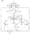
3 is a view showing a hydraulic circuit of the swing control device according to the first embodiment.
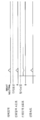
Fig. 4 is a time chart showing a change in the hydraulic pressure in the swing hydraulic motor when the upper swing body stops by turning and decelerating, and (a) shows a case in which no configuration for suppressing hunting phenomenon is provided. Indicates a case where the swing control device according to the first embodiment of the present invention is installed.
FIG. 5 is a diagram showing a hydraulic circuit of the swing control device according to the second embodiment. FIG.
FIG. 6 shows hydraulic pressure in the swing hydraulic motor when the driver performs the same operation as that of the swing operation lever shown in FIG. 4A when the swing control device according to the second embodiment is provided. Time chart indicating the change in.
FIG. 7 is a diagram illustrating a hydraulic circuit of the swing control device according to the third embodiment. FIG.
Fig. 8 shows hydraulic pressure in the swing hydraulic motor when the driver performs the same operation as that of the swing operation lever shown in Fig. 4A when the swing control device according to the third embodiment is installed. Time chart indicating the change in.
Fig. 9 is a time chart showing the change in the hydraulic pressure in the swing hydraulic motor when the swing operation lever is slightly operated when the shovel is installed on the inclined ground.

Next, an embodiment will be described with reference to the drawings.

1 is a side view showing a shovel equipped with a swing control device according to an embodiment of the present invention.

An upper revolving structure 3 is mounted on a lower traveling body 1 of a shovel via a revolving mechanism 2. The boom 4 is attached to the upper swing body 3. An arm 5 is attached to the tip of the boom 4, and a bucket 6 is attached to the tip of the arm 5. The boom 4, the arm 5, and the bucket 6 are hydraulically driven by the boom cylinder 7, the arm cylinder 8, and the bucket cylinder 9, respectively. The upper swing structure 3 is provided with a cabin 10, and a power source such as an engine is mounted.

FIG. 2 is a block diagram showing the configuration of a shovel driving system shown in FIG. 1. In Fig. 2, the mechanical dynamometer is shown by a double line, the high pressure hydraulic line by a thick line, the pilot line by a broken line, and the electric drive and control system by solid lines, respectively.

The engine 11 as a mechanical drive unit is connected to the main pump 14 and the pilot pump 15 as a hydraulic pump. A control valve 17 is connected to the main pump 14 via a high-pressure hydraulic line 16.

The control valve 17 is a control device for controlling the hydraulic system in the shovel. The traveling hydraulic motors 1A (for the right) and 1B (for the left), the boom cylinder 7, the arm cylinder 8, and the bucket cylinder 9 for the lower traveling body 1 are connected via a high pressure hydraulic line. It is connected to the control valve 17.

In addition, a swing hydraulic motor 21 for driving the swing mechanism 2 is connected to the control valve 17. The swing hydraulic motor 21 is connected to the control valve 17 via the hydraulic circuit of the swing control device, but the hydraulic circuit of the swing control device is not shown in FIG. The swing hydraulic device will be described later.

An operating device 26 is connected to the pilot pump 15 through a pilot line 25. [ The operating device 26 includes a lever 26A, a lever 26B, and a pedal 26C. The lever 26A, the lever 26B, and the pedal 26C are connected to the control valve 17 and the pressure sensor 29 via the hydraulic lines 27 and 28, respectively. The pressure sensor 29 is connected to a controller 30 that performs drive control of the electric machine. In this embodiment, the lever 26A functions as a turning operation lever.

The controller 30 is a control device as a main controller that performs drive control of the shovel. The controller 30 is composed of a CPU (Central Processing Unit) and an arithmetic processing apparatus including an internal memory, and is a device realized by executing a drive control program stored in the internal memory by the CPU.

An inclination sensor 32 for detecting the inclination angle of the shovel is provided in the upper swinging structure 3. When the shovel is provided on the inclined ground, the inclination sensor 32 supplies a signal indicating the inclination angle of the shovel to the controller 30. The inclination sensor 32 may be provided in the lower traveling body 1.

Next, a swing control device for controlling the driving of the swing hydraulic motor 21 will be described. The swing control device includes a swing hydraulic circuit for driving the swing hydraulic motor 21, and the swing hydraulic circuit is provided between the swing hydraulic motor 21 and the control valve 17.

3 is a diagram illustrating a hydraulic circuit of the swing control device 200 according to the first embodiment. First, a swing drive hydraulic circuit for driving the swing hydraulic motor 21 will be described. In FIG. 3, the swing drive hydraulic circuit is a hydraulic circuit provided between the swing hydraulic motor 21 and the control valve 17. The swing drive hydraulic circuit includes a hydraulic line 210A connecting the control valve 17 and the A port of the swing hydraulic motor, a hydraulic line 210B connecting the control valve 17 and the B port of the swing hydraulic motor, And a makeup hydraulic line 220 for connecting the hydraulic lines 210A and 210B to the tank 280.

Between the hydraulic line 210A and the make-up hydraulic line 220, a high pressure relief valve 230A is installed. When the hydraulic pressure of the hydraulic line 210A (that is, the hydraulic pressure at the A port of the swing hydraulic motor 21) is equal to or higher than the relief pressure of the high pressure relief valve 230A, the high pressure hydraulic fluid is supplied from the hydraulic line 210A. Flow through the relief valve 230A to the make-up hydraulic line 220, the working oil is low pressure is returned to the tank 280. The high pressure relief valve 230A and the make-up hydraulic line 220 constitute a high pressure relief circuit.

In addition, a check valve 240A is installed between the hydraulic line 210A and the makeup hydraulic line 220. When the hydraulic pressure of the hydraulic line 210A (that is, the hydraulic pressure in the A port of the swing hydraulic motor 21) is equal to or lower than a predetermined hydraulic pressure (make-up hydraulic pressure), the hydraulic oil in the tank 280 becomes the makeup hydraulic line 220. And flows into the hydraulic line 210A through the check valve 240A. In this way, the hydraulic oil of the hydraulic line 210A (that is, the hydraulic pressure in the A port of the swing hydraulic motor 21) is supplemented by the hydraulic oil from the make-up hydraulic line 220.

Similarly, a high pressure relief valve 230B is provided between the hydraulic line 210B and the makeup hydraulic line 220. When the hydraulic pressure of the hydraulic line 210B (that is, the hydraulic pressure at the port B of the swing hydraulic motor 21) is equal to or greater than the relief pressure of the high pressure relief valve 230B, the high pressure hydraulic fluid is supplied from the hydraulic line 210B. Flow through the relief valve 230B to the make-up hydraulic line 220, the working oil is low pressure is returned to the tank 280. The high pressure relief circuit 230B and the make-up hydraulic line 220 constitute a high pressure relief circuit.

In addition, a check valve 240B is installed between the hydraulic line 210B and the makeup hydraulic line 220. When the oil pressure of the hydraulic line 210B (that is, the oil pressure at the port B of the swing hydraulic motor 21) is equal to or lower than a predetermined oil pressure (make-up oil pressure), the hydraulic oil in the tank 280 becomes the make-up hydraulic line 220. And flows into the hydraulic line 210B through the check valve 240B. As a result, the hydraulic oil of the hydraulic line 210B (that is, the hydraulic pressure in the B port of the swing hydraulic motor 21) is replenished by the hydraulic oil from the make-up hydraulic line 220.

The high pressure hydraulic oil discharged from the main pump 14 is supplied to the control valve 17, and is supplied from the control valve 17 to the hydraulic line 210A or the hydraulic line 210B. When the control valve 17 is operated so that the high pressure hydraulic oil is supplied to the hydraulic line 210A, the hydraulic line 210B is connected to the tank 280. Therefore, the high pressure hydraulic oil is supplied to the A port of the swing hydraulic motor 21, drives the swing hydraulic motor 21 to become low pressure, and is returned to the tank 280 through the hydraulic line 210B. When the swing hydraulic motor 21 is driven, the swing mechanism 2 is driven, and the upper swing body 3 swings. The turning at this time is called turning in the right direction. That is, when the hydraulic pressure is supplied to the A port of the swing hydraulic motor, the upper swing structure 3 swings in the right direction.

On the other hand, when the control valve 17 is operated so that the high pressure hydraulic fluid is supplied to the hydraulic line 210B, the hydraulic line 210A is connected to the tank 280. Therefore, the high pressure hydraulic oil is supplied to the B port of the swing hydraulic motor 21, drives the swing hydraulic motor 21 to become low pressure, and is returned to the tank 280 through the hydraulic line 210A. When the swing hydraulic motor 21 is driven, the swing mechanism 2 is driven, and the upper swing body 3 swings. The turning at this time is called turning in the left direction. That is, when hydraulic pressure is supplied to the B port of the swing hydraulic motor, the upper swing body 3 swings leftward.

The control valve 17 is operated by the pilot pressure supplied from the operating device 26. Hydraulic pressure is supplied to the operating device 26 from the pilot pump 15, and the operating device 26 generates pilot pressure for operating the control valve 17 by using the hydraulic pressure.

That is, when the driver flips the turning operation lever 26A of the operating device 26 to the right in order to prioritize the upper swing body 3, the operating device 26 controls the control port 17A on the right side of the control valve 17. Supply pilot pressure. By the pilot pressure, the control valve 17 is operated so that the hydraulic line 210A is connected to the main pump 14 and the hydraulic line 210B is connected to the tank 280.

On the other hand, when the driver flips the turning operation lever 26A of the operating device 26 to the left in order to turn the upper swing body 3 to the left, the operating device 26 controls the control port 17B on the left side of the control valve 17. Supply pilot pressure. By the pilot pressure, the control valve 17 is operated so that the hydraulic line 210B is connected to the main pump 14 and the hydraulic line 210A is connected to the tank 280.

Although the structure described above is the structure of the turning drive apparatus 200 which drives and controls the turning hydraulic motor 21 for turning the upper swing body 3, in this embodiment, in addition to the structure mentioned above, the turning hydraulic motor 21 ) Is designed to suppress the hunting phenomenon that occurs when deceleration occurs.

The configuration for suppressing the hunting phenomenon includes a hydraulic line 250A for connecting the hydraulic line 210A and the tank 280, and a hydraulic line 250B for connecting the hydraulic line 210B and the tank 280. On / off valve 252A and diaphragm 254A are installed in the hydraulic line 250A. The hydraulic line 250B is provided with an on-off valve 252B and an aperture 254B.

On-off valves 252A and 252B are operated by signals from the controller 30. A pilot line for switching the pilot pressure supplied from the operating device 26 to the control port 17A to an electrical signal 256A connects the operating device 26 to the control port 17A of the control valve 17. It is connected to 258A. Further, a switch 256B for converting the pilot pressure supplied from the operating device 26 to the control port 17B into an electrical signal connects the operating device 26 with the control port 17B of the control valve 17. It is connected to the pilot line 258B.

When the pilot pressure is supplied from the operating device 26 to the control port 17A of the control valve 17, the switch 256A detects this and supplies a detection signal (electrical signal) to the controller 30. When the detection signal is supplied from the switch 256A, the controller 30 controls to close the on-off valve 252A and open the on-off valve 252B.

That is, when the driver flips the turning operation lever 26A to the right to make the upper swing body 3 turn to the right, the operating device 26 supplies the pilot pressure to the control port 17A on the right side of the control valve 17. Therefore, the switch 256A sends a detection signal to the controller 30. As a result, the controller 30 closes the on / off valve 252A and controls the open / close valve 252B to open. At this time, since the on-off valve 252A is closed, the high pressure hydraulic fluid from the control valve 17 does not flow into the hydraulic line 250A, but passes through the hydraulic line 210A to the A port of the turning hydraulic motor 21. Supplied. The hydraulic oil supplied to the A port drives the turning hydraulic motor 21, is discharged from the B port, flows back through the hydraulic line 210B, and returns to the tank 280. At this time, since the hydraulic line 210B connected to the B port is connected to the hydraulic line 250B, and the opening / closing valve 252B is open, a part of the hydraulic oil discharged from the B port passes through the hydraulic line 250B. It may return to 280.

As described above, the hunting reduction circuit is configured by the hydraulic line 250B, the open / close valve 252B, and the diaphragm 254B.

Similarly, when pilot pressure is supplied from the operating device 26 to the control port 17B of the control valve 17, the switch 256B detects this and supplies a detection signal (electrical signal) to the controller 30. When the detection signal is supplied from the switch 256B, the controller 30 closes the open / close valve 252B and controls the open / close valve 252A to open.

That is, when the driver flips the turning operation lever 26A to the left to turn the upper swing body 3 to the left, the operating device 26 supplies the pilot pressure to the control port 17B on the left side of the control valve 17. Therefore, the switch 256B sends a detection signal to the controller 30. As a result, the controller 30 controls the closing valve 252B to open and opens the closing valve 252A. At this time, since the on-off valve 252B is closed, the high pressure hydraulic fluid from the control valve 17 does not flow into the hydraulic line 250B, but passes through the hydraulic line 210B to the B port of the turning hydraulic motor 21. Supplied. The hydraulic oil supplied to the B port drives the turning hydraulic motor 21, is discharged from the A port, and flows back through the hydraulic line 210A to the tank 280. At this time, since the hydraulic line 210A connected to the A port is connected to the hydraulic line 250A, and the opening / closing valve 252A is open, a part of the hydraulic oil discharged from the A port is tanked via the hydraulic line 250A. It may return to 280.

As described above, the hunting reduction circuit is configured by the hydraulic line 250A, the on-off valve 252A, and the diaphragm 254A.

In the swing control device 200 having the hydraulic circuit having the above-described configuration, the operation when the swing operation lever 26A is suddenly returned to the neutral position and sudden swing deceleration is performed will be described.

First, the case where the structure which suppresses the hunting phenomenon which arises at the time of the deceleration of the swing hydraulic motor 21 for installation is not provided is demonstrated, referring FIG. 4 (a). 4 (a) is a time chart showing a change in the hydraulic pressure in the turning hydraulic motor 21 when the upper swing body 3 turns and decelerates and stops.

When the swing operation lever 26A is turned in the preferential direction at time t1, the supply of hydraulic pressure to the A port of the swing hydraulic motor 21 is started, and the oil pressure of the hydraulic lines 210A (A port) is increased. To start. At this time, the A port of the swing hydraulic motor 21 becomes the acceleration side hydraulic port. The operation amount of the swing operation lever 26A becomes the maximum at the time t2 (the state in which the swing operation lever 26A is turned to the right at the maximum), and then the maximum operation amount is maintained. At this time, the hydraulic pressure of the A port of the swing hydraulic motor starts to rise from the time t1 and becomes a constant value after the time t2. The hydraulic pressure of the A port is constant because the hydraulic pressure of the hydraulic line 210A reaches the relief pressure of the high pressure relief valve 230A. That is, the upper limit of the hydraulic pressure supplied to the A port of the swing hydraulic motor is determined by the high pressure relief valve 230A.

Since the hydraulic pressure is supplied to the A port of the swing hydraulic motor 21 from the time t1, the swing hydraulic motor 21 is driven by hydraulic pressure. As a result, the upper swing body 3 starts to rotate first. The turning speed goes up to time t3 after time t2.

Here, at time t3, the driver is operating the turning operation lever 26A back toward the half position in order to decelerate when the desired turning speed has been reached. Here, the half position represents the intermediate position between the maximum manipulated variable and the neutral position. Then, the supply of the hydraulic pressure to the hydraulic line 210A is stopped, and the hydraulic pressure of the A port of the swing hydraulic motor 21 decreases rapidly to zero. At this time, even when the hydraulic pressure supply to the A port is stopped at time t3, since the swing hydraulic motor 21 rotates by the inertia force of the upper swing body 3, the hydraulic pressure at the A port is lower than the make-up hydraulic pressure, and thus the tank 280 The hydraulic oil passing through the hydraulic oil and the high-pressure relief valve 230B in the c) flows into the hydraulic line 210A through the make-up hydraulic line 220 and the check valve 240A, and is supplied to the A port. Since this hydraulic fluid is discharged from the B port of the turning hydraulic motor 21, the oil pressure in the B port starts to rise rapidly from time t3. The B port of the turning hydraulic motor 21 at this time becomes a deceleration side hydraulic port (brake side hydraulic port). Due to the increase in the hydraulic pressure in the B port, the brake is applied by the turning hydraulic motor 21, and the acceleration of the upper swing body 3 is stopped. At this time, since the hydraulic line 210B is blocked, the hydraulic pressure in the B port of the swing hydraulic motor 21 and the hydraulic line 210B rises rapidly, and reaches the relief pressure of the high pressure relief valve 230B. By the way, since the operation amount of the turning operation lever 26A which the driver operates by the rapid deceleration of the upper turning body 3 fluctuates largely between time t3 and time t4, as shown to FIG. 4 (a), turning correspondingly In port A of the hydraulic motor 21, the oil pressure which has become zero at time t3 is raised and lowered again. In addition, the hydraulic pressure of the B port of the swing hydraulic motor 21 also varies greatly between the time t3 and the time t4. That is, the oil pressure in port B rapidly rises from the time t3 to reach the relief pressure of the high-pressure relief valve 230A, and then the operation of the swing operation lever 26A is shaken in the acceleration direction, and thus is accelerated again. , Drops sharply. Since the swing operation lever 26A is operated in the neutral position direction again, it is in a deceleration state again, and the pressure at the B port rapidly rises. Due to the fluctuations in the hydraulic pressure in the B port, a very small shock or vibration occurs as a hunting phenomenon in the swinging motion of the upper swing body 3.

When the change in the operation amount of the swing operation lever 26A disappears at time t4, the hydraulic pressure of the A port of the swing hydraulic motor 21 becomes the hydraulic pressure determined according to the operation amount (the amount of flipping) of the swing operation lever 26A. Thereafter, the turning hydraulic motor 21 is rotated at constant speed, and the upper swinging structure 3 continues to turn at the turning speed according to the driver's operation.

Subsequently, at time t5, the driver starts the operation so that the turning operation lever 26A is maximally flipped to the right again, so that the operation amount of the turning operation lever 26A is increased again to become the maximum operation amount. As a result, the hydraulic pressure supplied to the A port of the swing hydraulic motor 21 increases, reaches the relief pressure of the high-pressure relief valve 230A, and is maintained at the relief pressure.

Then, at time t6, the driver starts to return the turning operation lever 26A to the neutral position in order to stop the turning of the upper swing body 3. As a result, the oil pressure supplied to the A port of the swing hydraulic motor 21 decreases rapidly, and instead, the oil pressure of the B port rapidly rises. As a result of the sudden increase in the hydraulic pressure of the port B, a large brake is applied to the turning hydraulic motor 21, and the upper swing body 3 rapidly decelerates. The above-mentioned hunting phenomenon occurs due to the rapid deceleration of the upper swing structure 3, and the B port pressure of the swing hydraulic motor 21 fluctuates greatly, so that vibration occurs in the upper swing structure 3.

As described above, when the upper swing structure 3 is suddenly decelerated, the amount of operation of the driver's swing operation lever 26A varies, and vibration occurs in the upper swing structure 3 due to hunting. In this embodiment, in order to suppress this hunting phenomenon, the hydraulic line 250A having the on-off valve 252A and the diaphragm 254A supplies the hydraulic line 210A for supplying hydraulic pressure to the A port of the turning hydraulic motor 21. ), A hydraulic line 250B having an on / off valve 252B and an aperture 254B is connected to a hydraulic line 210B for supplying hydraulic pressure to the B port of the swing hydraulic motor 21.

FIG. 4B shows the turning hydraulic motor when the driver performs the same operation as that of the turning operation lever 26A shown in FIG. 4A when the turning control apparatus 200 is installed. It is a time chart showing a change in oil pressure in 21).

The operation and operation at each time t1 to t6 are the same as the operation and operation shown in Fig. 4A, but in the example shown in Fig. 4B, the occurrence of hunting phenomenon is suppressed. When rapid deceleration of the upper swing structure 3 is performed at time t3, the hydraulic pressure of the B port of the swing hydraulic motor 21 rises, but the rise is constant at the low pressure relief pressure in FIG.

That is, at time t3, the switch 256A detects the pilot pressure supplied from the swing operation lever 26A to the control port 17A of the control valve 17 and sends a detection signal to the controller 30. Upon receiving the detection signal, the controller 30 controls the opening / closing valve 252B to open. As a result, the hydraulic oil discharged from the B port of the swing hydraulic motor 21 flows to the tank 280 through the hydraulic line 210B. However, since the diaphragm 254B is provided in the middle of the hydraulic line 210B, and a predetermined flow path resistance is obtained, the hydraulic pressure of the hydraulic oil discharged from the B port of the turning hydraulic motor 21 after time t3 rises to some extent. . This hydraulic pressure generates an appropriate braking force, and the brakes are not suddenly applied by the turning hydraulic motor 21. Therefore, the deceleration of the upper swing body 3 is not excessively decelerated, nor is the deceleration affecting the operation of the driver's swing operation lever 26A, so that the occurrence of hunting phenomenon is suppressed.

The change in the hydraulic pressure in the B port of the swing hydraulic motor 21 at the time of turning stop at time t6 is also the same as the change in the hydraulic pressure in the B port after time t3. When switching from the turning state of the constant speed to the turning state of deceleration, the control valve 17 is controlled to narrow the hydraulic line 210 in response to the change in the pilot pressure, and the controller 30 opens / closes the valve 252B. Control to open As a result, the hydraulic oil discharged from the B port returns to the tank 280 through the diaphragm 254B, so that the hydraulic pressure in the B port does not rise rapidly. After time t6, the oil pressure in the B port rises appropriately, and when the oil pressure reaches the relief pressure of the high pressure relief valve 230B, it is maintained at the oil pressure. Thereafter, when the rotational speed of the swing hydraulic motor 21 decreases, the oil pressure at the B port decreases, and when the swing of the upper swing body 3 stops, the oil pressure becomes zero. As described above, the sudden deceleration does not occur even at the time of turning stop after time t6, and the occurrence of hunting phenomenon is suppressed because the driver's inertial force does not slow down which affects the operation of the turning operation lever 26A. Thus, when switching from the turning state of acceleration to the turning state of a fixed speed, or switching from the turning state of a constant speed to the turning state of deceleration, the hydraulic line of a deceleration side is narrowed in response to a change of pilot pressure. The control valve 17 is operated so that the controller 30 can open the hunting reduction circuit on the deceleration side, thereby suppressing the occurrence of the hunting phenomenon. In addition, the control is similarly performed when the motor is switched to the swinging state of deceleration from the rotating state of acceleration.

Next, the swing control apparatus 200A according to the second embodiment will be described with reference to FIG. 5. FIG. 5: is a figure which shows the hydraulic circuit of the turning control apparatus 200A which concerns on 2nd Embodiment.

In the configuration of the hydraulic circuit of the swing control device 200A shown in FIG. 5, the diaphragms 254A and 254B in the swing control device 200 according to the first embodiment shown in FIG. 3 are respectively low-pressure relief valves 260A, 260B). Therefore, in FIG. 5, the same code | symbol is attached | subjected to the component equivalent to the component shown in FIG. 3, and the description is abbreviate | omitted.

In the present embodiment, for example, the hydraulic oil discharged from the B port of the swing hydraulic motor at the time of the priority deceleration is returned to the tank 280 via the low pressure relief valve 260B. That is, the function of returning to the tank 280 while raising the oil pressure in B port to some extent at the time of deceleration is implement | achieved by the low pressure relief valve 260B instead of the aperture 254B. Therefore, in this embodiment, the hunting reduction circuit is comprised by the hydraulic line 250B, the on-off valve 252B, and the low pressure relief valve 260B. Similarly, a hunting reduction circuit is configured by the hydraulic line 250A, the on-off valve 252A and the low pressure relief valve 260A.

FIG. 6 shows the swing hydraulic motor 21 when the driver performs the same operation as that of the swing operation lever 26A shown in FIG. 4A when the swing control device 200A is installed. A time chart showing the change in oil pressure.

The operation and operation at each time t1 to t6 are the same as the operation and operation shown in Fig. 4A, but the hunting phenomenon is suppressed in the example shown in Fig. 6. If the upper swing structure 3 is suddenly decelerated at time t3, the hydraulic pressure of the B port of the swing hydraulic motor 21 increases, but the rise of the hydraulic pressure at the B port is a relief of the low pressure relief valve 260B. From the time point beyond the pressure, it becomes constant at the low pressure relief pressure.

That is, even if the on-off valve 252B opens at the time t3, the hydraulic fluid flows into the tank 280 via the hydraulic line 250B until the hydraulic pressure at the port B becomes the relief pressure of the low pressure relief valve 260B. Since it does not return, the oil pressure in the B port (oil pressure in the hydraulic line 210B) rises rapidly. However, when the hydraulic pressure in the B port (hydraulic in the hydraulic line 210B) becomes the relief pressure of the low pressure relief valve 260B, a part of the hydraulic oil discharged from the B port flows through the hydraulic line 250B and the low pressure relief valve ( 260B may be returned to tank 280. The low pressure relief valve 260B has a predetermined flow path resistance similar to the aperture 254B described above. As a result, the increase in the hydraulic pressure in the B port is suppressed, the sudden deceleration is suppressed, and the occurrence of hunting phenomenon is suppressed.

After time t6, the same turning deceleration as after time t3 is performed, the rise of the hydraulic pressure in the B port is suppressed, the sudden deceleration is suppressed, and the occurrence of hunting phenomenon is suppressed.

When the swing operation lever 26A is returned to the neutral position at time t7, the signal to the on-off valve 252B is not supplied, so the on-off valve 252B is closed. As a result, the working oil does not flow in the low pressure relief valve 260B, and the function of the low pressure relief valve relative to the hydraulic pressure in the B port does not work. Therefore, the oil pressure in the B port rises from the low pressure relief pressure and reaches the high pressure relief pressure. Thus, vibration can be suppressed at the time of turning stop.

Next, the turning control apparatus 200B which concerns on 3rd Embodiment is demonstrated, referring FIG. FIG. 7: is a figure which shows the hydraulic circuit of the swing control apparatus 200B which concerns on 3rd Embodiment.

The structure of the hydraulic circuit of the swing control apparatus 200B shown in FIG. 7 is the function of the low pressure relief valves 260A and 260B in the swing control apparatus 200A which concerns on 2nd Embodiment shown in FIG. 5, and a high pressure relief valve. The functions of 230A and 230B are combined into two stage relief valves 270A and 270B, respectively. In FIG. 7, the components which are the same as the components shown in FIG. 5 are given the same reference numerals, and the description thereof is omitted.

In the present embodiment, the high pressure relief valves 230A and 230B originally provided in the driving hydraulic circuit of the swing hydraulic motor 21 are respectively used as two-stage relief valves. The rise is suppressed, thereby suppressing the sudden deceleration of the upper swing structure 3 to suppress the occurrence of hunting. The switching of the relief pressures of the two-stage relief valves 270A and 270B is performed by a signal from the controller 30. For example, when the detection signal is supplied from the switch 256A to the controller 30, it is determined that the oil pressure in the B port is rapidly increased, and the controller 30 makes the second stage relief valve 270B at time t1. The switching signal is sent to turn on the function of the low pressure relief valve so that the relief valve also operates at a lower pressure relief pressure lower than that of the low pressure relief valve in the second embodiment, for example. When the swing operation lever 26A is operated at time t1, a signal is supplied to the two-stage relief valve 270B on the deceleration side, and the function of the low pressure relief valve is turned ON. Therefore, when the hydraulic pressure in the B port becomes equal to or more than the low pressure relief pressure, the working oil is returned to the tank 280 via the makeup hydraulic line 220. Thereby, even at the time t3, t6, even if an operator performs operation which returns 26 A of turning operation levers to a neutral position or a half position, generation of a hunting phenomenon can be suppressed.

If the swing operation lever 26A is returned to the neutral position at time t7, the signal to the two-stage relief valve 270B will not be supplied, so that the function of the low pressure relief valve will not function. Therefore, the oil pressure in the B port rises from the low pressure relief pressure and reaches the high pressure relief pressure. Thus, vibration can be suppressed at the time of turning stop. The change of the hydraulic pressure in the B port of the swing hydraulic motor 21 at this time becomes the same as the change shown in FIG. 6, as shown in FIG.

As described above, in the present embodiment, the hunting reduction circuit is configured by the function of the low pressure relief valve of the two-stage relief valve 270A and the make-up hydraulic line 220. Similarly, with the function of the low pressure relief valve of the two-stage relief valve 270B and the make-up hydraulic line 220, a hunting reduction circuit is configured.

In all of the above embodiments, when the shovel is provided on a flat surface and no hydraulic pressure is supplied from the control valve 17 to the swing hydraulic motor 21, the A port and the B port of the swing hydraulic motor 21 are supplied with hydraulic pressure. It was assumed that it did not occur. Here, when the shovel is provided on the inclined ground, when the center of gravity of the upper swing body 3 and the center of swing position are different, the turning force that the center of gravity of the upper swing body 3 tries to descend along the slope acts. Therefore, the oil pressure may be generated in the A port or the B port of the swing hydraulic motor 21 from the beginning. That is, when the shovel is inclined, the upper swing body 3 may try to swing only by gravity.

Under normal control, when the swing operating lever 26A is in the neutral position (that is, the swing operation is not performed), the hydraulic lines 210A connected to the A port and the hydraulic lines 210B connected to the B port are used. Both sides are in a blocked state, and the brake is applied to both turning directions by the turning hydraulic motor 21.

Even when the shovel is provided on an inclined ground, the brake is applied in both turning directions by the turning hydraulic motor 21, so that the upper swing body 3 does not turn. However, when the turning operation lever 26A is slightly operated when the shovel equipped with the above-mentioned turning control device is provided on the inclined ground and the turning force is generated in the upper turning body 3, the upper turning body 3 There is a fear of turning along the slope against the driver's intention.

Specifically, for example, a case where the shovel to which the swing control device 200 shown in FIG. 3 is mounted is provided on the inclined ground where the swing force acts on the upper swing body 3 in the right direction. In this case, when the swing operating lever 26A is in the neutral position and the upper swing structure 3 is not swing-operated, the swing hydraulic motor 21 is caused by the swing force applied to the upper swing structure 3 due to the inclination. Oil pressure at port B is increasing. In this state, as shown in Fig. 9, when the swing operating lever 26A is returned to the neutral position as soon as it is operated slightly in the priority direction, the hydraulic pressure is supplied to the A port of the swing hydraulic motor 21, The on-off valve 252B connected to the B port is opened through the hydraulic line 210B and the hydraulic line 250B. When the on-off valve 252B opens, the oil pressure in port B decreases, and when the oil pressure in port A becomes larger than the oil pressure in port B as the oil pressure in port A increases, the upper swing structure 3 Starts a priority meeting.

However, if the upper swing body 3 starts the priority swing and then performs the operation of returning the swing operation lever 26A toward the half position, the hydraulic pressure in the A port decreases, but the opening / closing valve 252B is opened. Therefore, brake pressure cannot be generated in the B port. For this reason, the weight of the upper swing body 3 cannot be supported, and the upper swing body 3 first rotates along the inclination until the swing operation lever 26A is returned to the neutral position.

In order to prevent this unintentional turning, it is preferable to control the opening / closing valves 252A and 252B not to open when shovels are provided on the inclined ground. For example, when the detection signal from any of the switches 256A and 256B is output when the swing operating lever 26A is not operated, the controller 30 determines that the shovel is installed on the inclined ground, and turns. Even when the operation lever 26A is operated, the on-off valves 252A and 252B are controlled not to open. As a result, as shown in FIG. 9, the hydraulic pressure at the B port of the swing hydraulic motor 21 rises again when the swing operation lever 26A is returned to the neutral position, so that the swing hydraulic motor ( It is possible to return to the braked state by 21).

In addition, you may judge whether the shovel is provided in the inclined place by the controller 30 based on the signal from the inclination sensor 32 provided in the shovel. That is, when the inclination angle detected by the inclination sensor 32 is larger than the predetermined value, the controller 30 controls the opening / closing valves 252A and 252B not to open even if the turning operation lever 26A is operated. . Incidentally, the inclination may be detected not only by the inclination sensor 32 but also by the detection values of the hydraulic sensors provided in the turning hydraulic lines 210A and 210B.

1 Lower traveling body
1A, 1B traveling hydraulic motor
2 swivel mechanism
3 upper swivel
4 boom
5 Cancer
6 buckets
7 boom cylinder
8 dark cylinder
9 Bucket cylinder
10 Cabins
11 engine
14 Main pump
15 Pilot Pump
16 High Pressure Hydraulic Line
17 Control Valve
21 slewing hydraulic motor
25 pilot lines
26 Operation device
26A swing control lever
26B lever
26C pedal
27 Hydraulic lines
28 Hydraulic lines
29 Pressure sensor
30 controller
32 tilt sensor
200, 200A, 200B Swivel Control
210A, 210B Hydraulic Line
220 Makeup Hydraulic Line
230A, 230B High Pressure Relief Valve
240A, 240B Check Valve
250A, 250B Hydraulic Line
252A, 252B On / Off Valve
254A, 254B Aperture
256A, 256B Switch
258A, 258B Pilot Lines
260A, 260B Low Pressure Relief Valve
270A, 270B 2-stage relief valve
280 tank

Claims (8)

A swing control device for swinging a swinging body by a hydraulic motor,
A high pressure relief circuit for relief of the hydraulic pressure of the hydraulic line for supplying hydraulic oil to the first relief pressure to drive the hydraulic motor;
Hunting reduction circuit which suppresses the hydraulic pressure of the hydraulic line connected to the deceleration side hydraulic port from which hydraulic oil is discharged when the hydraulic motor is being driven to a pressure lower than the first relief pressure.
Lt; / RTI &
A turning control device for opening said hunting reduction circuit connected to said deceleration-side hydraulic port before the operating lever for operating the swing of said swinging body returns to the neutral position.
The method according to claim 1,
And a turning control device which opens the hunting reduction circuit in response to an input by an operation of the operation lever.
The method according to claim 1 or 2,
And the hunting reduction circuit is closed when the hydraulic pressure of the deceleration-side hydraulic port is larger than the hydraulic pressure of the acceleration-side hydraulic port, and the closing control device is kept closed regardless of the operation of the operation lever.
The method according to claim 1 or 2,
When the inclination detected by at least one of the inclination sensor and the oil pressure sensor of the oil pressure line is larger than a predetermined inclination, the hunting reduction circuit is closed and the swing keeping the hunting reduction circuit is closed regardless of the operation of the operation lever. Control unit.
The method according to any one of claims 1 to 4,
The hunting reduction circuit,
On-off valve,
Aperture with predetermined flow path resistance
Swing control device having a.
The method according to any one of claims 1 to 4,
The hunting reduction circuit,
On-off valve,
Low pressure relief valve operating at a second relief pressure lower than the first relief pressure
Swing control device having a.
The method according to any one of claims 1 to 4,
A turning control device in which the function of the hunting reduction circuit is incorporated into the high pressure relief valve of the high pressure relief circuit to be a two-stage relief valve.
The method according to any one of claims 1 to 7,
And the hunting reduction circuit is closed when it is determined that the swing structure is installed on the inclined ground.
KR1020130024364A 2012-03-30 2013-03-07 Rotary controller KR101623488B1 (en)

Applications Claiming Priority (2)

Application Number Priority Date Filing Date Title
JP2012082871A JP5872363B2 (en) 2012-03-30 2012-03-30 Swing control device
JPJP-P-2012-082871 2012-03-30

Publications (2)

Publication Number Publication Date
KR20130111287A true KR20130111287A (en) 2013-10-10
KR101623488B1 KR101623488B1 (en) 2016-05-23

Family

ID=48095487

Family Applications (1)

Application Number Title Priority Date Filing Date
KR1020130024364A KR101623488B1 (en) 2012-03-30 2013-03-07 Rotary controller

Country Status (5)

Country Link
US (1) US10106955B2 (en)
EP (1) EP2644785B1 (en)
JP (1) JP5872363B2 (en)
KR (1) KR101623488B1 (en)
CN (1) CN103362169B (en)

Cited By (1)

* Cited by examiner, † Cited by third party
Publication number Priority date Publication date Assignee Title
WO2021221861A1 (en) * 2020-04-28 2021-11-04 Caterpillar Inc. Hystat swing motion actuation, monitoring, and control system

Families Citing this family (11)

* Cited by examiner, † Cited by third party
Publication number Priority date Publication date Assignee Title
JP6469646B2 (en) * 2014-02-24 2019-02-13 住友建機株式会社 Excavator and control method of excavator
KR102128630B1 (en) * 2014-03-24 2020-06-30 두산인프라코어 주식회사 control method for Swing motor of Hydraulic system
JP5873217B1 (en) * 2014-06-04 2016-03-01 株式会社小松製作所 Construction machine control system, construction machine, and construction machine control method
WO2016035902A1 (en) * 2014-09-02 2016-03-10 볼보 컨스트럭션 이큅먼트 에이비 Apparatus for controlling swing of construction machine and control method thereof
KR102426641B1 (en) 2014-11-10 2022-07-27 스미토모 겐키 가부시키가이샤 Work Machine
JP6469844B2 (en) * 2015-03-27 2019-02-13 住友重機械工業株式会社 Excavator and excavator driving method
JP6907779B2 (en) * 2017-07-24 2021-07-21 コベルコ建機株式会社 Construction machinery
WO2019078077A1 (en) 2017-10-20 2019-04-25 住友建機株式会社 Shovel
EP3943674A4 (en) * 2019-03-19 2022-07-13 Sumitomo Construction Machinery Co., Ltd. Excavator
JP7227817B2 (en) * 2019-03-26 2023-02-22 住友建機株式会社 working machine
CN110409538B (en) * 2019-06-28 2021-10-29 三一重机有限公司 Hydraulic excavator rotation brake control method and device, controller and storage medium

Family Cites Families (20)

* Cited by examiner, † Cited by third party
Publication number Priority date Publication date Assignee Title
US3238722A (en) * 1963-09-24 1966-03-08 Vsesouzny Nii Str I Dorozhnogo Platform slewing gear of single-motor universal type crane-excavator
JPS57205639A (en) * 1981-06-12 1982-12-16 Hitachi Constr Mach Co Ltd Closing device for oil-pressure circuit for inertia-mass driving
US4680929A (en) * 1983-04-04 1987-07-21 Kubota, Ltd. Swivelling working vehicle
ES2047675T3 (en) * 1989-07-26 1994-03-01 Kobe Steel Ltd METHOD OF CONTROLLING THE TURNING OPERATION OF A TURNING MECHANISM AND A HYDRAULIC CONTROL SYSTEM TO CARRY OUT THE SAME.
JP2555499B2 (en) * 1990-04-02 1996-11-20 日立建機株式会社 Hydraulic drive for civil engineering and construction machinery
US5285643A (en) 1990-04-02 1994-02-15 Hitachi Construction Machinery Co., Ltd. Hydraulic drive system for civil-engineering and construction machine
JP2531264Y2 (en) * 1991-10-31 1997-04-02 住友建機株式会社 Inertial control system for hydraulic equipment
JP2586877Y2 (en) * 1992-08-07 1998-12-14 株式会社小松製作所 Turning hydraulic device for upper turning type vehicle
JPH06173299A (en) * 1992-12-02 1994-06-21 Komatsu Ltd Turning hydraulic circuit for construction machine
KR960023541A (en) 1994-12-08 1996-07-20 안자키 사토루 Reverse Actuator of Hydraulic Actuator
US5941155A (en) * 1996-11-20 1999-08-24 Kabushiki Kaisha Kobe Seiko Sho Hydraulic motor control system
JP3408099B2 (en) * 1997-02-07 2003-05-19 新キャタピラー三菱株式会社 Swivel working device
JP2000266006A (en) * 1999-03-15 2000-09-26 Komatsu Ltd Turning controlling device
JP2003106305A (en) * 2001-09-28 2003-04-09 Kobelco Contstruction Machinery Ltd Gyrating control circuit
JP4096900B2 (en) * 2004-03-17 2008-06-04 コベルコ建機株式会社 Hydraulic control circuit for work machines
DE102005006321A1 (en) * 2005-02-11 2006-08-17 Hydac Fluidtechnik Gmbh Valve, in particular proportional pressure relief valve
KR100974275B1 (en) * 2007-12-17 2010-08-06 볼보 컨스트럭션 이키프먼트 홀딩 스웨덴 에이비 shock absorption device and method thereof for excavator
KR101572288B1 (en) * 2008-03-26 2015-11-26 카야바 고교 가부시기가이샤 Controller of hybrid construction machine
JP5175870B2 (en) 2010-01-13 2013-04-03 川崎重工業株式会社 Drive control device for work machine
JP5504423B2 (en) * 2010-08-27 2014-05-28 日立建機株式会社 Hydraulic drive device for hydraulic working machine

Cited By (2)

* Cited by examiner, † Cited by third party
Publication number Priority date Publication date Assignee Title
WO2021221861A1 (en) * 2020-04-28 2021-11-04 Caterpillar Inc. Hystat swing motion actuation, monitoring, and control system
US11585071B2 (en) 2020-04-28 2023-02-21 Caterpillar Inc. Hystat swing motion actuation, monitoring, and control system

Also Published As

Publication number Publication date
EP2644785B1 (en) 2016-02-10
CN103362169B (en) 2016-05-04
KR101623488B1 (en) 2016-05-23
US20130255243A1 (en) 2013-10-03
CN103362169A (en) 2013-10-23
JP2013213315A (en) 2013-10-17
US10106955B2 (en) 2018-10-23
EP2644785A1 (en) 2013-10-02
JP5872363B2 (en) 2016-03-01

Similar Documents

Publication Publication Date Title
KR20130111287A (en) Rotary controller
JP2013213315A5 (en)
US5063742A (en) Method of controlling swing motion of a revolving superstructure and hydraulic control system for carrying out same
US8881519B2 (en) Slewing type working machine
US10422109B2 (en) Shovel and method of controlling shovel
JP6693842B2 (en) crane
EP2706151A1 (en) Rotation-type working machine
JP2017179923A (en) Hydraulic system for work machine
US4644849A (en) Locking apparatus of inertial mass drive hydraulic circuit system
JP2011017431A (en) Electrohydraulic swing drive device
WO2014073337A1 (en) Construction machine
WO2015056520A1 (en) Hybrid-type construction machine
JP2018071311A (en) Energy regenerative system
CN111615574B (en) Rotary type construction machine
JP2004044309A (en) Rotation control device for construction machine
JP6707515B2 (en) Hydraulic system of work equipment
JP4114609B2 (en) Construction machinery
JP2011075045A (en) Hydraulic controller for hydraulic working machine
JP2010112075A (en) Device for controlling speed of actuator of working machine
JP3503472B2 (en) Revolving body brake device for construction machinery
JP3586046B2 (en) Hydraulic motor control device
JP2020139275A (en) Working machine
JP4028090B2 (en) Hydraulic controller for work machine
JP2019007586A (en) Hydraulic drive system
JPH06193730A (en) Hydraulic motor drive circuit for traveling of work vehicle

Legal Events

Date Code Title Description
A201 Request for examination
E902 Notification of reason for refusal
AMND Amendment
E902 Notification of reason for refusal
AMND Amendment
E90F Notification of reason for final refusal
AMND Amendment
E601 Decision to refuse application
E801 Decision on dismissal of amendment
AMND Amendment
X701 Decision to grant (after re-examination)
GRNT Written decision to grant
FPAY Annual fee payment

Payment date: 20190429

Year of fee payment: 4