KR20130111029A - Susceptor for chemical vapor deposition apparatus and chemical vapor deposition apparatus having the same - Google Patents
Susceptor for chemical vapor deposition apparatus and chemical vapor deposition apparatus having the same Download PDFInfo
- Publication number
- KR20130111029A KR20130111029A KR1020120033489A KR20120033489A KR20130111029A KR 20130111029 A KR20130111029 A KR 20130111029A KR 1020120033489 A KR1020120033489 A KR 1020120033489A KR 20120033489 A KR20120033489 A KR 20120033489A KR 20130111029 A KR20130111029 A KR 20130111029A
- Authority
- KR
- South Korea
- Prior art keywords
- substrate
- chemical vapor
- vapor deposition
- deposition apparatus
- Prior art date
Links
- 238000005229 chemical vapour deposition Methods 0.000 title claims abstract description 70
- 239000000758 substrate Substances 0.000 claims abstract description 143
- 238000000034 method Methods 0.000 claims description 34
- 238000010438 heat treatment Methods 0.000 claims description 25
- 238000000926 separation method Methods 0.000 claims description 20
- OKTJSMMVPCPJKN-UHFFFAOYSA-N Carbon Chemical compound [C] OKTJSMMVPCPJKN-UHFFFAOYSA-N 0.000 claims description 18
- 239000007789 gas Substances 0.000 claims description 13
- 239000012495 reaction gas Substances 0.000 claims description 10
- 229910052799 carbon Inorganic materials 0.000 claims description 9
- 238000000151 deposition Methods 0.000 claims description 9
- 229910002804 graphite Inorganic materials 0.000 claims description 9
- 239000010439 graphite Substances 0.000 claims description 9
- HBMJWWWQQXIZIP-UHFFFAOYSA-N silicon carbide Chemical compound [Si+]#[C-] HBMJWWWQQXIZIP-UHFFFAOYSA-N 0.000 claims description 9
- 230000008021 deposition Effects 0.000 claims description 7
- 230000006698 induction Effects 0.000 claims description 5
- 230000005855 radiation Effects 0.000 claims description 5
- HMDDXIMCDZRSNE-UHFFFAOYSA-N [C].[Si] Chemical compound [C].[Si] HMDDXIMCDZRSNE-UHFFFAOYSA-N 0.000 claims 4
- 238000006243 chemical reaction Methods 0.000 description 6
- IUHFWCGCSVTMPG-UHFFFAOYSA-N [C].[C] Chemical compound [C].[C] IUHFWCGCSVTMPG-UHFFFAOYSA-N 0.000 description 4
- 239000013078 crystal Substances 0.000 description 3
- 150000002736 metal compounds Chemical class 0.000 description 3
- 239000004065 semiconductor Substances 0.000 description 3
- 239000012159 carrier gas Substances 0.000 description 2
- 238000012986 modification Methods 0.000 description 2
- 230000004048 modification Effects 0.000 description 2
- 230000002093 peripheral effect Effects 0.000 description 2
- 239000000126 substance Substances 0.000 description 2
- 239000010409 thin film Substances 0.000 description 2
- 150000001875 compounds Chemical class 0.000 description 1
- 238000005260 corrosion Methods 0.000 description 1
- 230000007797 corrosion Effects 0.000 description 1
- 239000006185 dispersion Substances 0.000 description 1
- 230000000694 effects Effects 0.000 description 1
- 238000005516 engineering process Methods 0.000 description 1
- 239000010408 film Substances 0.000 description 1
- 238000002347 injection Methods 0.000 description 1
- 239000007924 injection Substances 0.000 description 1
- 239000011810 insulating material Substances 0.000 description 1
- 239000007791 liquid phase Substances 0.000 description 1
- 239000002184 metal Substances 0.000 description 1
- 239000007769 metal material Substances 0.000 description 1
- 150000004767 nitrides Chemical class 0.000 description 1
- 238000000197 pyrolysis Methods 0.000 description 1
- 238000005507 spraying Methods 0.000 description 1
- 239000002912 waste gas Substances 0.000 description 1
Images


Classifications
-
- H—ELECTRICITY
- H01—ELECTRIC ELEMENTS
- H01L—SEMICONDUCTOR DEVICES NOT COVERED BY CLASS H10
- H01L21/00—Processes or apparatus adapted for the manufacture or treatment of semiconductor or solid state devices or of parts thereof
- H01L21/02—Manufacture or treatment of semiconductor devices or of parts thereof
- H01L21/02104—Forming layers
-
- C—CHEMISTRY; METALLURGY
- C23—COATING METALLIC MATERIAL; COATING MATERIAL WITH METALLIC MATERIAL; CHEMICAL SURFACE TREATMENT; DIFFUSION TREATMENT OF METALLIC MATERIAL; COATING BY VACUUM EVAPORATION, BY SPUTTERING, BY ION IMPLANTATION OR BY CHEMICAL VAPOUR DEPOSITION, IN GENERAL; INHIBITING CORROSION OF METALLIC MATERIAL OR INCRUSTATION IN GENERAL
- C23C—COATING METALLIC MATERIAL; COATING MATERIAL WITH METALLIC MATERIAL; SURFACE TREATMENT OF METALLIC MATERIAL BY DIFFUSION INTO THE SURFACE, BY CHEMICAL CONVERSION OR SUBSTITUTION; COATING BY VACUUM EVAPORATION, BY SPUTTERING, BY ION IMPLANTATION OR BY CHEMICAL VAPOUR DEPOSITION, IN GENERAL
- C23C16/00—Chemical coating by decomposition of gaseous compounds, without leaving reaction products of surface material in the coating, i.e. chemical vapour deposition [CVD] processes
- C23C16/44—Chemical coating by decomposition of gaseous compounds, without leaving reaction products of surface material in the coating, i.e. chemical vapour deposition [CVD] processes characterised by the method of coating
- C23C16/458—Chemical coating by decomposition of gaseous compounds, without leaving reaction products of surface material in the coating, i.e. chemical vapour deposition [CVD] processes characterised by the method of coating characterised by the method used for supporting substrates in the reaction chamber
- C23C16/4582—Rigid and flat substrates, e.g. plates or discs
- C23C16/4583—Rigid and flat substrates, e.g. plates or discs the substrate being supported substantially horizontally
- C23C16/4584—Rigid and flat substrates, e.g. plates or discs the substrate being supported substantially horizontally the substrate being rotated
-
- C—CHEMISTRY; METALLURGY
- C23—COATING METALLIC MATERIAL; COATING MATERIAL WITH METALLIC MATERIAL; CHEMICAL SURFACE TREATMENT; DIFFUSION TREATMENT OF METALLIC MATERIAL; COATING BY VACUUM EVAPORATION, BY SPUTTERING, BY ION IMPLANTATION OR BY CHEMICAL VAPOUR DEPOSITION, IN GENERAL; INHIBITING CORROSION OF METALLIC MATERIAL OR INCRUSTATION IN GENERAL
- C23C—COATING METALLIC MATERIAL; COATING MATERIAL WITH METALLIC MATERIAL; SURFACE TREATMENT OF METALLIC MATERIAL BY DIFFUSION INTO THE SURFACE, BY CHEMICAL CONVERSION OR SUBSTITUTION; COATING BY VACUUM EVAPORATION, BY SPUTTERING, BY ION IMPLANTATION OR BY CHEMICAL VAPOUR DEPOSITION, IN GENERAL
- C23C16/00—Chemical coating by decomposition of gaseous compounds, without leaving reaction products of surface material in the coating, i.e. chemical vapour deposition [CVD] processes
- C23C16/44—Chemical coating by decomposition of gaseous compounds, without leaving reaction products of surface material in the coating, i.e. chemical vapour deposition [CVD] processes characterised by the method of coating
- C23C16/46—Chemical coating by decomposition of gaseous compounds, without leaving reaction products of surface material in the coating, i.e. chemical vapour deposition [CVD] processes characterised by the method of coating characterised by the method used for heating the substrate
-
- H—ELECTRICITY
- H01—ELECTRIC ELEMENTS
- H01L—SEMICONDUCTOR DEVICES NOT COVERED BY CLASS H10
- H01L21/00—Processes or apparatus adapted for the manufacture or treatment of semiconductor or solid state devices or of parts thereof
- H01L21/67—Apparatus specially adapted for handling semiconductor or electric solid state devices during manufacture or treatment thereof; Apparatus specially adapted for handling wafers during manufacture or treatment of semiconductor or electric solid state devices or components ; Apparatus not specifically provided for elsewhere
- H01L21/683—Apparatus specially adapted for handling semiconductor or electric solid state devices during manufacture or treatment thereof; Apparatus specially adapted for handling wafers during manufacture or treatment of semiconductor or electric solid state devices or components ; Apparatus not specifically provided for elsewhere for supporting or gripping
- H01L21/687—Apparatus specially adapted for handling semiconductor or electric solid state devices during manufacture or treatment thereof; Apparatus specially adapted for handling wafers during manufacture or treatment of semiconductor or electric solid state devices or components ; Apparatus not specifically provided for elsewhere for supporting or gripping using mechanical means, e.g. chucks, clamps or pinches
- H01L21/68714—Apparatus specially adapted for handling semiconductor or electric solid state devices during manufacture or treatment thereof; Apparatus specially adapted for handling wafers during manufacture or treatment of semiconductor or electric solid state devices or components ; Apparatus not specifically provided for elsewhere for supporting or gripping using mechanical means, e.g. chucks, clamps or pinches the wafers being placed on a susceptor, stage or support
- H01L21/68771—Apparatus specially adapted for handling semiconductor or electric solid state devices during manufacture or treatment thereof; Apparatus specially adapted for handling wafers during manufacture or treatment of semiconductor or electric solid state devices or components ; Apparatus not specifically provided for elsewhere for supporting or gripping using mechanical means, e.g. chucks, clamps or pinches the wafers being placed on a susceptor, stage or support characterised by supporting more than one semiconductor substrate
Abstract
Description
본 발명은 화학 기상 증착 장치용 서셉터 및 이를 구비하는 화학 기상 증착 장치에 관한 것이다.
The present invention relates to a susceptor for a chemical vapor deposition apparatus and a chemical vapor deposition apparatus having the same.
일반적으로 화학적 기상 증착(Chemical Vapor Deposition; CVD)은 여러 가지 기판상에 다양한 결정막을 성장시키는데 주요한 방법으로 사용되고 있다. 일반적으로 액상 성장법에 비해 성장시킨 결정의 품질이 뛰어나지만, 결정의 성장속도가 상대적으로 느린 단점이 있다. 이것을 극복하기 위해 한 번의 성장 싸이클에서 여러 장의 기판상에 동시에 성장을 실행하는 방법이 널리 채택되고 있다.In general, chemical vapor deposition (CVD) is used as a main method for growing various crystal films on various substrates. Generally, the quality of the grown crystal is superior to that of the liquid phase growth method, but the growth rate of the crystal is relatively slow. In order to overcome this problem, a method of simultaneously performing growth on a plurality of substrates in one growth cycle is widely adopted.
최근 반도체 소자의 미세화와 고효율, 고출력 LED 개발 등으로 CVD 기술 중 금속유기 화학적 기상 증착법(Metal Organic Chemical Vapor Deposition; MOCVD)이 각광받고 있으며, 이러한 MOCVD는 화학적 기상 성장법(CVD) 중의 한가지로 유기금속의 열분해반응을 이용해 반도체 기판 상에 금속 화합물을 퇴적, 부착시키는 화합물 반도체의 기상 성장법을 말한다.Recently, metal organic chemical vapor deposition (MOCVD) has been attracting attention in the CVD technology due to miniaturization of semiconductor devices and development of high efficiency and high output LED. Such MOCVD is one of chemical vapor deposition (CVD) And a metal compound is deposited on the semiconductor substrate by using a pyrolysis reaction of the compound semiconductor.
이와 같은 화학 기상 증착법은 반응 챔버 내부로 공급된 반응가스가 가열된 기판의 상부 표면에서 화학반응을 일으켜 에피택셜 박막을 성장시키는 것이다.In the chemical vapor deposition method, the reaction gas supplied into the reaction chamber is chemically reacted at the upper surface of the heated substrate to grow an epitaxial thin film.
이때, 기판 표면의 전 영역에서 에피택셜층이 균일한 두께를 가지도록 하는 것이 필요한데, 이를 위해서는 기판을 가열하는 온도가 기판의 전 영역에 걸쳐 균일하도록 조절하는 것이 가장 중요하다.
At this time, it is necessary to make the epitaxial layer have a uniform thickness throughout the entire surface of the substrate. For this purpose, it is most important to adjust the temperature for heating the substrate uniformly over the entire region of the substrate.
따라서 서셉터에 놓인 기판에 온도차이가 발생하는 것을 방지하여 기판의 온도 균일도를 향상시킴으로써 우수한 품질의 기판을 제조할 수 있는 화학 기상 증착 장치용 서셉터 및 이를 구비하는 화학 기상 증착 장치가 요구되고 있다.Therefore, there is a need for a susceptor for a chemical vapor deposition apparatus and a chemical vapor deposition apparatus having the same, which can produce a high quality substrate by preventing temperature difference between the substrate placed on the susceptor and improving the temperature uniformity of the substrate. .
또한 서셉터에 적재되는 기판의 개수를 늘릴 수 있도록 서셉터의 구조를 변경하여 생산성을 향상시킬 수 있는 서셉터가 요구되고 있다.
In addition, there is a need for a susceptor capable of improving productivity by changing the structure of the susceptor so as to increase the number of substrates loaded on the susceptor.
본 발명의 일 실시형태에 따른 화학 기상 증착 장치용 서셉터는, 구동장치와 연결되는 회전축이 하부에 결합되며, 상기 회전축의 회전에 의하여 회전구동하는 회전체; 및 상기 회전체의 상부면에 적어도 하나 구비되며, 기판이 올려지는 안착부와, 상기 안착부의 내측에 형성되어 바닥면이 상기 안착부에 안착된 상기 기판의 하부면과 이격되도록 형성된 오목부를 구비하는 포켓; 을 포함하고, 상기 적어도 하나의 포켓 중에서 상기 회전축과 대응하는 영역에 위치하는 포켓은, 상기 기판에 균일한 열전달을 위해 상기 회전축과 대응하는 위치에서 돌출된 볼록부를 구비함을 특징으로 한다.Susceptor for chemical vapor deposition apparatus according to an embodiment of the present invention, the rotating shaft is coupled to the lower portion coupled to the drive device, the rotating body to rotate by rotation of the rotating shaft; And at least one provided on an upper surface of the rotating body and having a seating portion on which a substrate is placed, and a recess formed in the seating portion so that a bottom surface is spaced apart from a lower surface of the substrate seated on the seating portion. pocket; And a pocket positioned in an area corresponding to the rotation axis among the at least one pocket, and having a convex portion protruding from the position corresponding to the rotation axis for uniform heat transfer to the substrate.
상기 포켓의 바닥면과 상기 기판의 하부면 사이의 간격은, 상기 볼록부가 구비된 상기 포켓 영역이 상기 볼록부가 구비되지 않은 상기 포켓 영역 보다 더 좁은 것을 특징으로 한다.The space between the bottom surface of the pocket and the bottom surface of the substrate is characterized in that the pocket region with the convex portion is narrower than the pocket region without the convex portion.
상기 볼록부는 상면이 평평하게 형성됨을 특징으로 한다.The convex portion is characterized in that the upper surface is formed flat.
상기 볼록부의 측벽은 상기 포켓의 중심에서 멀어질수록 상기 기판의 하부면과 상기 포켓의 바닥면의 간격이 커지도록 경사지게 형성된 것을 특징으로 한다.The side wall of the convex portion is formed to be inclined such that the distance between the lower surface of the substrate and the bottom surface of the pocket increases as the distance from the center of the pocket.
상기 안착부의 외측에는 상기 포켓에 배치된 기판의 분리이탈이 용이하도록 상기 안착부의 외측 테두리를 따라 일정 깊이로 함몰형성되는 환고리형 함몰부가 형성되어 있는 것을 특징으로 한다.The outer side of the seating portion is characterized in that the ring-shaped recessed portion is formed to be recessed to a certain depth along the outer edge of the seating portion to facilitate separation and separation of the substrate disposed in the pocket.
상기 회전체는 카본(carbon) 또는 탄화 규소(SiC)가 코팅된 그라파이트(graphite)로 이루어지는 회전구조물인 것을 특징으로 한다.The rotating body is characterized in that the rotating structure consisting of graphite (carbon) coated with carbon (carbon) or silicon carbide (SiC).
상기 안착부는 상기 포켓의 밑면으로부터 돌기한 형상인 것을 특징으로 한다.The seating portion is characterized in that the shape protruding from the bottom surface of the pocket.
상기 안착부는 상기 포켓과 동일한 중심을 갖는 링 형상인 것을 특징으로 한다.
The seating portion is characterized in that the ring shape having the same center as the pocket.
본 발명의 다른 실시형태에 따른 화학 기상 증착 장치용 서셉터는, 구동장치와 연결되는 회전축이 하부에 결합되며, 상기 회전축의 회전에 의하여 회전구동하는 회전체; 및 상기 회전체의 상부면에 구비되며, 기판이 올려지는 안착부와, 상기 안착부의 내측에 형성되어 바닥면이 상기 안착부에 안착된 상기 기판의 하부면과 이격되도록 형성된 오목부를 구비하는 다수의 포켓; 을 포함하고, 상기 다수의 포켓 중에서 상기 회전체의 하부에 상기 회전축이 구비되지 않은 영역에 위치하는 포켓은, 상기 포켓의 바닥면이 상기 안착부에 안착된 상기 기판의 하부면과 일정 간격 이격되도록 형성되고, 상기 다수의 포켓 중에서 상기 회전체의 하부에 상기 회전축이 구비된 영역에 위치하는 포켓은, 상기 기판에 균일한 열전달을 위해 상기 회전축과 대응하는 위치에서 돌출된 볼록부를 구비함을 특징으로 한다.Susceptor for chemical vapor deposition apparatus according to another embodiment of the present invention, a rotating shaft coupled to the drive unit is coupled to the lower portion, the rotating body to rotate by rotation of the rotating shaft; And a recess provided on an upper surface of the rotating body and having a seating portion on which a substrate is placed, and a recess formed in the seating portion so that a bottom surface is spaced apart from a bottom surface of the substrate seated on the seating portion. pocket; And a pocket positioned in an area where the rotating shaft is not provided below the rotating body among the plurality of pockets, such that a bottom surface of the pocket is spaced apart from the lower surface of the substrate seated on the seating part at a predetermined interval. And a pocket positioned in an area in which the rotating shaft is provided below the rotating body among the plurality of pockets, the convex part protruding from a position corresponding to the rotating shaft for uniform heat transfer to the substrate. do.
상기 회전체의 하부에 상기 회전축이 구비된 영역에 위치하는 상기 포켓의 바닥면과 상기 기판의 하부면 사이의 간격은, 상기 볼록부가 구비된 상기 포켓 영역이 상기 볼록부가 구비되지 않은 상기 포켓 영역 보다 더 좁은 것을 특징으로 한다The interval between the bottom surface of the pocket and the bottom surface of the substrate, which is located in an area where the rotating shaft is provided below the rotating body, is smaller than that of the pocket area in which the convex portion is provided. Characterized by a narrower
상기 볼록부는 상면이 평평하게 형성됨을 특징으로 한다.The convex portion is characterized in that the upper surface is formed flat.
상기 볼록부의 측벽은 상기 오목부의 중심에서 멀어질수록 상기 기판의 하부면과 상기 오목부의 바닥면의 간격이 커지도록 경사지게 형성된 것을 특징으로 한다.The side wall of the convex portion is formed to be inclined such that the distance between the bottom surface of the substrate and the bottom surface of the concave portion increases as the distance from the center of the concave portion.
상기 안착부의 외측에는 상기 포켓에 배치된 기판의 분리이탈이 용이하도록 상기 안착부의 외측 테두리를 따라 일정 깊이로 함몰형성되는 환고리형 함몰부가 형성되어 있는 것을 특징으로 한다.The outer side of the seating portion is characterized in that the ring-shaped recessed portion is formed to be recessed to a certain depth along the outer edge of the seating portion to facilitate separation and separation of the substrate disposed in the pocket.
상기 회전체는 카본(carbon) 또는 탄화 규소(SiC)가 코팅된 그라파이트(graphite)로 이루어지는 회전구조물인 것을 특징으로 한다.The rotating body is characterized in that the rotating structure consisting of graphite (carbon) coated with carbon (carbon) or silicon carbide (SiC).
상기 안착부는 상기 포켓의 밑면으로부터 돌기한 형상인 것을 특징으로 한다.The seating portion is characterized in that the shape protruding from the bottom surface of the pocket.
상기 안착부는 상기 포켓과 동일한 중심을 갖는 링 형상인 것을 특징으로 한다.
The seating portion is characterized in that the ring shape having the same center as the pocket.
본 발명의 또 다른 실시형태에 의한 화학 기상 증착 장치는, 가스 유입구를 통해 반응가스를 유입하여 증착을 가능하게 하는 챔버; 상기 챔버 내에 구비되고, 구동장치와 연결되는 회전축이 하부에 결합되며 상기 회전축의 회전에 의하여 회전구동하는 회전체 및 상기 회전체의 상부면에 적어도 하나 구비되며, 기판이 올려지는 안착부와, 상기 안착부의 내측에 형성되어 바닥면이 상기 안착부에 안착된 상기 기판의 하부면과 이격되도록 형성된 오목부를 구비하는 포켓을 구비하는 서셉터; 및 상기 서셉터의 하부에 구비되어 상기 기판을 가열하는 가열수단; 을 포함하고, 상기 적어도 하나의 포켓 중에서 상기 회전축과 대응하는 영역에 위치하는 상기 포켓은, 상기 기판에 균일한 열전달을 위해 상기 회전축과 대응하는 위치에서 돌출된 볼록부를 구비하는 것을 특징으로 한다.Chemical vapor deposition apparatus according to another embodiment of the present invention, the chamber for introducing the reaction gas through the gas inlet to enable deposition; Is provided in the chamber, the rotary shaft is coupled to the lower portion is coupled to the lower portion and is provided with at least one on the upper surface of the rotating body and the rotating body driven by the rotation of the rotating shaft, the seating portion on which the substrate is raised, A susceptor having a pocket formed on an inner side of a seating portion, the pocket having a concave portion formed to be spaced apart from a lower surface of the substrate seated on the seating portion; And heating means provided under the susceptor to heat the substrate. And a pocket located in an area corresponding to the rotation axis among the at least one pocket, and having a convex portion protruding at a position corresponding to the rotation axis for uniform heat transfer to the substrate.
상기 포켓의 바닥면과 상기 기판의 하부면 사이의 간격은, 상기 볼록부가 구비된 상기 포켓 영역이 상기 볼록부가 구비되지 않은 상기 포켓 영역 보다 더 좁은 것을 특징으로 한다.The space between the bottom surface of the pocket and the bottom surface of the substrate is characterized in that the pocket region with the convex portion is narrower than the pocket region without the convex portion.
상기 볼록부는 상면이 평평하게 형성됨을 특징으로 한다.The convex portion is characterized in that the upper surface is formed flat.
상기 볼록부의 측벽은 상기 포켓의 중심에서 멀어질수록 상기 기판의 하부면과 상기 포켓의 바닥면의 간격이 커지도록 경사지게 형성된 것을 특징으로 한다.The side wall of the convex portion is formed to be inclined such that the distance between the lower surface of the substrate and the bottom surface of the pocket increases as the distance from the center of the pocket.
상기 안착부의 외측에는 상기 포켓에 배치된 기판의 분리이탈이 용이하도록 상기 안착부의 외측 테두리를 따라 일정 깊이로 함몰형성되는 환고리형 함몰부가 형성되어 있는 것을 특징으로 한다.The outer side of the seating portion is characterized in that the ring-shaped recessed portion is formed to be recessed to a certain depth along the outer edge of the seating portion to facilitate separation and separation of the substrate disposed in the pocket.
상기 회전체는 카본(carbon) 또는 탄화 규소(SiC)가 코팅된 그라파이트(graphite)로 이루어지는 회전구조물인 것을 특징으로 한다.The rotating body is characterized in that the rotating structure consisting of graphite (carbon) coated with carbon (carbon) or silicon carbide (SiC).
상기 안착부는 상기 포켓의 밑면으로부터 돌기한 형상인 것을 특징으로 한다.The seating portion is characterized in that the shape protruding from the bottom surface of the pocket.
상기 안착부는 상기 포켓과 동일한 중심을 갖는 링 형상인 것을 특징으로 한다.The seating portion is characterized in that the ring shape having the same center as the pocket.
상기 가열수단은 전기히터, 고주파유도, 적외선방사 및 레이저로 이루어진 군에서 선택된 어느 하나인 것을 특징으로 한다.
The heating means is characterized in that any one selected from the group consisting of electric heater, high frequency induction, infrared radiation and laser.
본 발명의 또 다른 실시형태에 의한 화학 기상 증착 장치는 가스 유입구를 통해 반응가스를 유입하여 증착을 가능하게 하는 챔버; 상기 챔버 내에 구비되고, 구동장치와 연결되는 회전축이 하부에 결합되며 상기 회전축의 회전에 의하여 회전구동하는 회전체 및 상기 회전체의 상부면에 구비되며, 기판이 올려지는 안착부와, 상기 안착부의 내측에 형성되어 바닥면이 상기 안착부에 안착된 상기 기판의 하부면과 이격되도록 형성된 오목부를 구비하는 다수의 포켓; 을 구비하는 서셉터; 및 상기 서셉터의 하부에 구비되어 상기 기판을 가열하는 가열수단; 을 포함하고, 상기 회전체의 하부에 상기 회전축이 구비되지 않은 영역에 위치하는 상기 포켓은, 상기 포켓의 바닥면이 상기 안착부에 안착된 상기 기판의 하부면과 일정 간격 이격되도록 형성되고, 상기 회전체의 하부에 상기 회전축이 구비된 영역에 위치하는 상기 포켓은, 상기 기판에 균일한 열전달을 위해 상기 회전축과 대응하는 위치에서 돌출된 볼록부를 구비하는 것을 특징으로 한다.Chemical vapor deposition apparatus according to another embodiment of the present invention comprises a chamber for allowing the deposition of the reaction gas through the gas inlet port; A rotating shaft provided in the chamber and connected to a driving device is coupled to a lower portion, and is provided on a rotating body rotating by the rotation of the rotating shaft and an upper surface of the rotating body, and a seating portion on which a substrate is raised, and the seating portion. A plurality of pockets formed on an inner side thereof and having recesses formed to be spaced apart from a lower surface of the substrate seated on the seating portion; A susceptor having a; And heating means provided under the susceptor to heat the substrate. Included, wherein the pocket located in the area of the lower portion of the rotating body is not provided with the rotating shaft, the bottom surface of the pocket is formed so as to be spaced apart from the lower surface of the substrate seated on the seating portion, The pocket located in an area where the rotating shaft is provided below the rotating body may include a convex portion protruding from a position corresponding to the rotating shaft for uniform heat transfer to the substrate.
상기 회전체의 하부에 상기 회전축이 구비된 영역에 위치하는 상기 포켓의 바닥면과 상기 기판의 하부면 사이의 간격은, 상기 볼록부가 구비된 상기 포켓 영역이 상기 볼록부가 구비되지 않은 상기 포켓 영역 보다 더 좁은 것을 특징으로 한다.The interval between the bottom surface of the pocket and the bottom surface of the substrate, which is located in an area where the rotating shaft is provided below the rotating body, is smaller than that of the pocket area in which the convex portion is provided. It is characterized by a narrower.
상기 볼록부는 상면이 평평하게 형성됨을 특징으로 한다.The convex portion is characterized in that the upper surface is formed flat.
상기 볼록부의 측벽은 상기 오목부의 중심에서 멀어질수록 상기 기판의 하부면과 상기 오목부의 바닥면의 간격이 커지도록 경사지게 형성된 것을 특징으로 한다.The side wall of the convex portion is formed to be inclined such that the distance between the bottom surface of the substrate and the bottom surface of the concave portion increases as the distance from the center of the concave portion.
상기 안착부의 외측에는 상기 포켓에 배치된 기판의 분리이탈이 용이하도록 상기 안착부의 외측 테두리를 따라 일정 깊이로 함몰형성되는 환고리형 함몰부가 형성되어 있는 것을 특징으로 한다.The outer side of the seating portion is characterized in that the ring-shaped recessed portion is formed to be recessed to a certain depth along the outer edge of the seating portion to facilitate separation and separation of the substrate disposed in the pocket.
상기 회전체는 카본(carbon) 또는 탄화 규소(SiC)가 코팅된 그라파이트(graphite)로 이루어지는 회전구조물인 것을 특징으로 한다.The rotating body is characterized in that the rotating structure consisting of graphite (carbon) coated with carbon (carbon) or silicon carbide (SiC).
상기 안착부는 상기 포켓의 밑면으로부터 돌기한 형상인 것을 특징으로 한다.The seating portion is characterized in that the shape protruding from the bottom surface of the pocket.
상기 안착부는 상기 포켓과 동일한 중심을 갖는 링 형상인 것을 특징으로 한다.The seating portion is characterized in that the ring shape having the same center as the pocket.
상기 가열수단은 전기히터, 고주파유도, 적외선방사 및 레이저로 이루어진 군에서 선택된 어느 하나인 것을 특징으로 한다.
The heating means is characterized in that any one selected from the group consisting of electric heater, high frequency induction, infrared radiation and laser.
본 발명에 의하면, 화학 기상 증착 장치용 서셉터에서 기판이 올려지는 포켓의 바닥면과 기판의 하부면 사이의 간격을 조절하여, 기판에 온도 차이가 발생하는 것을 방지하여 우수한 품질의 기판을 제조할 수 있는 효과가 있다.According to the present invention, by adjusting the distance between the bottom surface of the pocket and the bottom surface of the pocket on which the substrate is mounted in the susceptor for chemical vapor deposition apparatus to prevent the temperature difference occurs in the substrate to produce a good quality substrate It can be effective.
또한 화학 기상 증착 장치용 서셉터에 적재되는 기판의 수를 늘려 생산성을 향상시킬 수 있는 효과가 있다.
In addition, it is possible to increase productivity by increasing the number of substrates loaded on the susceptor for chemical vapor deposition apparatus.
도 1은 본 발명의 일 실시형태에 따른 화학 기상 증착 장치를 도시한 것이다.
도 2는 본 발명의 일 실시형태에 의한 화학 기상 증착 장치용 서셉터의 평면도이다.
도 3은 도 2에 도시한 화학 기상 증착 장치용 서셉터를 X-X'축에서 도시한 상태를 나타내는 단면도이다.
도 4a는 도 2에 도시한 화학 기상 증착 장치용 서셉터에서 원주방향으로 일정간격을 두고 구비된 제1 포켓을 나타내는 단면도이다.
도 4b는 도 4a에 도시한 제1 포켓을 나타내는 확대 사시도이다.
도 5a는 도 2에 도시한 화학 기상 증착 장치용 서셉터에서 회전 중심면에 구비된 제2 포켓을 나타내는 단면도이다.
도 5b는 도 5a에 도시한 제2 포켓을 나타내는 확대 사시도이다.
도 6은 본 발명의 다른 실시형태에 의한 화학 기상 증착 장치용 서셉터의 평면도이다.
도 7a는 도 6에 도시한 화학 기상 증착 장치용 서셉터를 Y-Y'축에서 도시한 상태를 나타내는 단면도이다.
도 7b는 도 7a에 도시한 화학 기상 증착 장치용 서셉터의 제3 포켓을 나타내는 확대 사시도이다.1 illustrates a chemical vapor deposition apparatus according to one embodiment of the present invention.
It is a top view of the susceptor for chemical vapor deposition apparatuses which concerns on one Embodiment of this invention.
FIG. 3 is a cross-sectional view showing the susceptor for chemical vapor deposition apparatus shown in FIG. 2, taken along the line X-X '.
4A is a cross-sectional view illustrating a first pocket provided at regular intervals in a circumferential direction in the susceptor for chemical vapor deposition apparatus shown in FIG. 2.
FIG. 4B is an enlarged perspective view showing the first pocket shown in FIG. 4A.
FIG. 5A is a cross-sectional view illustrating a second pocket provided in the center of rotation of the susceptor for the chemical vapor deposition apparatus illustrated in FIG. 2.
FIG. 5B is an enlarged perspective view showing the second pocket shown in FIG. 5A.
6 is a plan view of a susceptor for chemical vapor deposition apparatuses according to another embodiment of the present invention.
FIG. 7A is a cross-sectional view illustrating the susceptor for chemical vapor deposition apparatus shown in FIG. 6, taken along the line Y-Y '. FIG.
FIG. 7B is an enlarged perspective view showing the third pocket of the susceptor for chemical vapor deposition apparatus shown in FIG. 7A.
본 발명의 실시형태에 따른 화학 기상 증착 장치용 서셉터 및 이를 구비하는 화학 기상 증착 장치에 관한 사항을 도면을 참조하여 설명한다. 그러나, 본 발명의 실시형태는 여러 가지 다른 형태로 변형될 수 있으며, 본 발명의 범위가 이하 설명되는 실시예로 한정되는 것은 아니다. 본 발명의 실시형태는 본 발명이 속하는 기술분야에서 통상의 지식을 가진 자에게 본 발명을 보다 완전하게 설명하기 위하여 제공되는 것이다. The matter regarding the susceptor for chemical vapor deposition apparatuses which concern on embodiment of this invention, and the chemical vapor deposition apparatus provided with this is demonstrated with reference to drawings. However, embodiments of the present invention may be modified in various other forms, and the scope of the present invention is not limited to the examples described below. Embodiments of the present invention are provided to more completely explain the present invention to those skilled in the art.
따라서, 도면에 도시된 구성요소들의 형상 및 크기 등은 보다 명확한 설명을 위하여 과장될 수 있으며, 도면 상에서 실질적으로 동일한 구성과 기능을 가진 구성요소들은 동일한 참조부호를 사용할 것이다.
Therefore, the shape and size of the components shown in the drawings may be exaggerated for more clear description, components having substantially the same configuration and function in the drawings will use the same reference numerals.
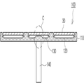
도 1은 본 발명의 일 실시형태에 따른 화학 기상 증착 장치를 도시한 것이다.1 illustrates a chemical vapor deposition apparatus according to one embodiment of the present invention.
도 1을 참조하면, 화학 기상 증착 장치(10)는 일정크기의 내부공간을 갖는 챔버(20)와, 상기 챔버(20) 내에 회전 가능하게 배치되어 복수개의 기판(30)이 올려지는 제1 서셉터(susceptor)(100)와, 상기 제1 서셉터(100)의 하부에 배치되어 열을 제공하는 가열수단(40) 및 상기 챔버(20)의 상부면으로부터 제1 서셉터(100)의 직상부까지 연장되는 가스 유입구(50)를 포함하여 구성된다.
Referring to FIG. 1, the chemical
상기 챔버(20)는 가스 유입구(50)를 통해 그 내부로 유입된 반응가스와 증착 대상물인 기판(30)간의 화학적 기상 반응이 이루어져 에피택셜층이 상기 기판(30)의 상부면에 증착 및 성장되도록 소정 크기의 내부공간을 제공하는 수직 원통형 구조물이다.The
상기 챔버(20)는 내마모성 및 내부식성이 우수한 메탈재질로 이루어지며, 내부면에는 고온 분위기를 견딜 수 있도록 단열재가 구비될 수도 있다.The
그리고, 적어도 하나의 기판(30)이 장착되는 제1 서셉터(100) 및 가열수단(40)을 내부에 구비하며, 상기 기판(30)과의 화학적 기상 반응이 종료된 폐가스를 외부로 배출하기 위한 배기구(미도시)를 구비한다.In addition, the
상기 가스 유입구(50)는 상기 챔버(20)의 상부측에 구비되어 하부측에서 회전하는 제1 서셉터(100) 위로 반응가스를 수직분사하는 샤워헤드 형 구조로 구비될 수 있다.The
또한, 상기 가스 유입구(50)는 상기 챔버(20)의 측단부 둘레를 따라 구비되어, 복수개의 분사노즐을 통해 상기 챔버(20)의 주변부로부터 중심부로 반응가스를 수평분사하는 유성형(planetary) 구조로 구비될 수도 있다.In addition, the
상기 가열수단(40)은 상기 기판(30)이 탑재되는 상기 제1 서셉터(100)의 하부측 근방에 배치되어 상기 기판(30)을 가열하기 위한 열을 상기 제1 서셉터(100)에 제공한다. 이러한 가열수단(40)은 전기히터, 고주파유도, 적외선방사, 레이저 등 중에서 어느 하나로 구비될 수 있다. The heating means 40 is disposed near the lower side of the
그리고, 상기 챔버(20)에는 상기 제1 서셉터(100)의 외부면이나 상기 가열수단(40)에 근접하도록 배치되어 상기 챔버(20)의 내부 분위기 온도를 수시로 측정하고, 측정값을 근거로 하여 가열온도를 조절할 수 있도록 온도센서(미도시)를 구비하는 것이 바람직하다.In addition, the
이러한 화학 기상 증착장치(10)에서는 상기 제1 서셉터(100)의 상부면 근방까지 연장된 가스 유입구(50)를 통하여 반응가스인 소스 가스(source gas)와 캐리어 가스(carrier gas)가 제1 서셉터(100)의 상부면 중앙영역으로 유입된다. 따라서 유입되는 반응가스가 높은 온도의 기판(30) 상에서 화학적 증착 반응으로 인해 기판(30)의 표면에 질화물 박막을 형성하고, 잔류 가스나 분산물은 챔버(20)의 벽면을 타고 하부로 배출된다.
In the chemical
도 2 내지 도 5를 참조하여 상기 서셉터의 구조에 대해 보다 자세히 설명한다.The structure of the susceptor will be described in more detail with reference to FIGS. 2 to 5.
도 2는 본 발명의 일 실시형태에 의한 화학 기상 증착 장치용 서셉터의 평면도이고, 도 3은 도 2에 도시한 화학 기상 증착 장치용 서셉터를 X-X'축에서 도시한 상태를 나타내는 단면도이고, 도 4a는 도 2에 도시한 화학 기상 증착 장치용 서셉터에서 원주방향으로 일정간격을 두고 구비된 제1 포켓을 나타내는 단면도이고, 도 4b는 도 4a에 도시한 제1 포켓을 나타내는 확대 사시도이고, 도 5a는 도 2에 도시한 화학 기상 증착 장치용 서셉터에서 회전 중심면에 구비된 제2 포켓을 나타내는 단면도이고, 도 5b는 도 5a에 도시한 제2 포켓을 나타내는 확대 사시도이다.FIG. 2 is a plan view of a susceptor for chemical vapor deposition apparatuses according to an embodiment of the present invention, and FIG. 3 is a cross-sectional view showing a state of the susceptor for chemical vapor deposition apparatuses shown in FIG. 2, taken along the line X-X '. 4A is a cross-sectional view illustrating a first pocket provided at regular intervals in a circumferential direction in the susceptor for a chemical vapor deposition apparatus illustrated in FIG. 2, and FIG. 4B is an enlarged perspective view illustrating the first pocket illustrated in FIG. 4A. 5A is a cross-sectional view showing a second pocket provided in the rotational center plane in the susceptor for chemical vapor deposition apparatus shown in FIG. 2, and FIG. 5B is an enlarged perspective view showing the second pocket shown in FIG. 5A.
도 2 및 도 3을 참조하면, 상기 제1 서셉터(100)는 제1 회전체(110), 제1 포켓(120), 제2 포켓(130) 및 제1 회전축(140)을 포함하여 구성된다.2 and 3, the
본 명세서에서 회전 중심면은 화학 기상 증착 장치용 서셉터의 하부에 회전축이 형성되어 있어서 가열수단이 구비되지 않는 영역, 즉 회전 중심 영역(C)을 포함하는 회전체의 중심부를 가리키는 것으로 정의한다. In the present specification, the rotational center plane is defined as pointing to the center of the rotating body including a rotational axis formed in the lower part of the susceptor for chemical vapor deposition apparatus, that is, not provided with heating means, that is, the rotational center area (C).
상기 제1 회전체(110)는 카본(carbon) 또는 탄화 규소(SiC)가 코팅된 그라파이트(graphite)로 이루어지는 회전구조물이며, 반응가스가 공급되는 챔버(20) 내에서 용이하게 회전하도록 디스크 형태를 가진다. The first
상기 제1 회전체(110)의 상부면에는 금속 화합물을 화학적으로 증착하기 위한 기판(30)이 놓여지는 제1 포켓(120)이 상기 제1 회전체(110)의 회전 중심을 기준으로 하여 원주방향으로 일정간격을 두고 동일면 상에 복수개 구비되고, 또한 상기 제1 회전체(110)의 회전 중심면에도 제2 포켓(130)이 구비된다.The
그러나, 본 발명은 도 2에 도시된 포켓의 배치 및 수로 한정되는 것이 아니고, 예를 들면 기판의 지름에 따라 변경 가능하다.However, the present invention is not limited to the arrangement and the number of pockets shown in FIG. 2, and can be changed depending on, for example, the diameter of the substrate.
이에 따라, 상기 제1 회전체(110)의 제1 및 제2 포켓(120)(130)을 통해 다수의 기판(30)을 동시에 회전시켜 에피텍셜(epitaxial)층을 성장시키는 것이 가능하다.
Accordingly, it is possible to grow an epitaxial layer by simultaneously rotating the plurality of
상기 제1 회전체(110)의 하부면에는 미도시된 구동장치와 연결되는 제1 회전축(140)이 결합하며, 상기 구동장치의 구동에 의해 상기 제1 회전축(140)이 일방향으로 회전하는 경우 상기 제1 회전체(110)는 상기 제1 회전축(140)과 더불어 일방향으로 회전구동한다.When the first
상기 제1 및 제2 포켓(120)(130)은 상기 제1 회전체(110)의 상부면에 적어도 하나 구비되므로, 상기 제1 및 제2 포켓(120)(130)은 일반적인 환형 기판(30)의 형상과 대응되는 형상을 가지며, 상기 기판(30)을 용이하게 배치 및 제거할 수 있도록 상기 기판(30)의 지름보다 큰 지름으로 형성된다.
Since the first and
도 4a 및 도 4b 에 도시된 바와 같이, 화학 기상 증착 장치용 서셉터에서 원주방향으로 일정간격을 두고 구비된 제1 포켓(120)에는 각각 제1 안착부(121), 제1 오목부(122) 및 제1 함몰부(123)가 형성되어 있다. 상기 기판(30)을 제1 포켓(120)의 제1 안착부(121)에 올려서 에피택셜층을 성장시킨다. As shown in FIGS. 4A and 4B, the
상기 제1 포켓(120)은 제1 안착부(121)를 제외하고 기판(30)과 접촉하지 않는다. 상기 제1 안착부(121)는 접촉면을 가지고 있고, 그 접촉면에서 기판(30)과 접하고 있다. 상기 제1 안착부(121)는 상기 제1 포켓(120)의 밑면으로부터 돌기한 형상이고, 상기 제1 포켓(120)과 동일한 중심을 갖는 링 형상일 수 있다. 상기 제1 안착부(121)의 내측측벽 및 외측측벽은 각각 기판(30)에 대하여 수직이나, 이에 한정되는 것은 아니고 제1 안착부(121)와 기판(30)의 접촉면적이 작아지도록 제1 안착부(121)의 양측벽이 경사지게 형성될 수 있다.The
상기 제1 오목부(122)는 상기 제1 안착부(121)의 내측에 형성되고 원형으로 오목하게 형성되어 있다. 기판이 올려지는 제1 포켓(120)의 제1 오목부(122)의 바닥면과 기판(30)의 하부면(31) 사이에 일정한 간격을 갖는 에어 갭(air gap)(124)이 형성되어 있어 상기 제1 안착부(121)에 올려진 기판(30)을 균일하게 가열 할 수 있다. 따라서 가열수단(40)에 열이 가해지면 상기 제1 포켓(120)에 구비된 기판(30)은 동일한 온도로 가열된다.
The
상기 제1 안착부(121)의 외측에는 상기 제1 포켓(120)에 배치된 기판의 증착 완료 후 상기 기판(30)의 분리이탈이 용이하도록 상기 제1 안착부(121)의 외측 테두리를 따라 일정 깊이로 함몰형성되는 환고리형 제1 함몰부(123)가 형성되어 있다.
The outer side of the
도 5a 및 도 5b에 도시된 바와 같이, 본 발명의 일 실시형태에 따른 화학 기상 증착 장치용 서셉터에서 회전 중심면에 구비된 제2 포켓(130)에는 제2 안착부(131), 제2 오목부(132) 및 제2 함몰부(133)가 형성되어 있다. 기판(30)을 제2 포켓(130)의 제2 안착부 (131)에 올려서 에피택셜층을 성장시킨다. 5A and 5B, in the susceptor for chemical vapor deposition apparatus according to the exemplary embodiment of the present invention, a
상기 제2 포켓(130)은 제2 안착부(131)를 제외하고 기판(30)과 접촉하지 않는다. 상기 제2 안착부(131)는 접촉면을 가지고 있고, 그 접촉면에서 기판(30)과 접하고 있다. 상기 제2 안착부(131)는 상기 제2 포켓(130)의 밑면으로부터 돌기한 형상이고, 상기 제2 포켓(130)과 동일한 중심을 갖는 링 형상일 수 있다. 상기 제2 안착부(131)의 내측측벽 및 외측측벽은 각각 기판(30)에 대하여 수직이나, 이에 한정되는 것은 아니고 제2 안착부(131)와 기판(30)의 접촉면적이 작아지도록 제2 안착부(131)의 양측벽이 경사지게 형성될 수 있다.The
상기 제2 오목부(132)는 상기 제2 안착부(131)의 내측에 형성되고 원형으로 오목하게 형성되어 있다. The second
이때 회전 중심 영역(C)을 포함하는 회전 중심면에 구비된 제2 포켓(130)의 일부 하부에는 상기 제1 회전체(110)를 회전구동시키는 제1 회전축(130)이 구비되어 있으므로, 상기 제1 회전체(110)를 포함하는 상기 제1 서셉터(100)에 열을 제공하는 가열수단(40)이 구비될 수 없다. 따라서 회전 중심면에 구비된 제2 포켓(130)의 중심 부위에는 기판(30)의 온도가 낮게 된다. At this time, a part of the
따라서 상기 제2 안착부(131)에 올려진 기판(30)을 균일하게 가열하기 위하여, 회전 중심 영역(C)에 보다 더 열전달이 잘 되도록 제2 포켓(130)의 바닥면을 형성한다. 즉 회전 중심 영역(C)에서 제2 포켓(130)의 제2 오목부(132)의 바닥면과 기판(30)의 하부면(31) 사이의 간격을 회전 중심 영역(C)이 아닌 제2 포켓(130)의 제2 오목부(132)의 바닥면과 기판(30)의 하부면(31) 사이의 간격 보다 좁게 형성한다. Therefore, in order to uniformly heat the
보다 구체적으로는, 제2 포켓(130)의 제2 오목부(132) 중에서 하부에 가열수단(40)이 위치하지 않은 영역, 즉 회전 중심 영역(C)에 상기 제2 오목부(132)의 바닥면으로부터 돌기한 형상으로 볼록부(134)를 형성한다. More specifically, the second
여기서 볼록부(134)의 상면은 평평하도록 형성하고, 상기 볼록부(134)의 측벽은 상기 제2 오목부(132)의 중심에서 멀어질수록 제2 포켓(130)의 제2 오목부(132)의 바닥면과 기판(30)의 하부면(31) 사이의 간격이 멀어지도록 양측벽이 경사지게 형성할 수 있다. 그러나 이에 한정되는 것은 아니다.Here, the upper surface of the
따라서 상기 볼록부(134)에 의하여 제2 포켓(130)의 제2 오목부(132) 중에서 하부에 가열수단(40)이 위치하지 않은 영역, 즉 회전 중심 영역(C)에서는 제2 오목부(132)의 바닥면과 기판(30)의 하부면(31) 사이의 간격이 하부에 가열수단(40)이 위치하는 제2 포켓(130) 영역, 즉 상기 볼록부(134)가 없는 제2 오목부(132)의 바닥면과 기판(30)의 하부면(31) 사이의 간격(135)보다 좁게 형성된다.Therefore, the second
이와 같이 제2 오목부(132)의 바닥면과 기판(30)의 하부면(31) 사이의 간격을 회전 중심 영역(C)과 주변부에 있어서 다르게 형성하면, 제2 포켓(130)의 제2 오목부(132)의 바닥면과 기판(30)의 하부면(31) 사이의 간격이 좁은 부분, 즉 볼록부(134)가 형성된 부분에서는 상기 기판(30)에 더 효과적으로 열이 전달되므로 기판이 전체적으로 균일한 온도로 가열될 수 있다.As such, when the distance between the bottom surface of the second
또한 상술한 바와 같이 서셉터의 회전 중심면의 온도 차이에 의하여 종래에는 화학 기상 증착 장치용 서셉터의 회전 중심면에는 포켓을 설치할 수 없었으나, 회전 중심면에도 포켓을 구비할 수 있게 되어 생산성이 향상되는 효과가 있다.
In addition, as described above, due to the temperature difference between the center of rotation of the susceptor, a pocket cannot be installed in the center of rotation of the susceptor for chemical vapor deposition apparatus. There is an effect to be improved.
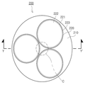
도 6은 본 발명의 다른 실시형태에 의한 화학 기상 증착 장치용 서셉터의 평면도이고, 도 7a는 도 6에 도시한 화학 기상 증착 장치용 서셉터를 Y-Y'축에서 도시한 상태를 나타내는 단면도이고, 도 7b는 도 7a에 도시한 화학 기상 증착 장치용 서셉터의 제3 포켓을 나타내는 확대 사시도이다.FIG. 6 is a plan view of a susceptor for chemical vapor deposition apparatuses according to another embodiment of the present invention, and FIG. 7A is a cross-sectional view showing a state of the susceptor for chemical vapor deposition apparatuses shown in FIG. 6, taken along the line Y-Y '. FIG. 7B is an enlarged perspective view showing the third pocket of the susceptor for chemical vapor deposition apparatus shown in FIG. 7A.
도 6 내지 도 7b를 참조하면, 제2 서셉터(200)는 제2 회전체(210), 제3 포켓(220), 제2 회전축(240)을 포함하여 구성된다.
6 to 7B, the
상기 제2 회전체(210)의 상부면에는 금속 화합물을 화학적으로 증착하기 위한 기판(30)이 놓여지는 제3 포켓(220)이 상기 제2 회전체(210) 상부에서 동일면 상에 복수개 구비된다. 본 실시형태에서는 일 실시형태와 달리 제3 포켓(220)이 제2 회전체(210) 중심부분에 제2 회전축(240)이 형성된 회전 중심 영역(C)까지 그 지름이 형성되어 있다. A plurality of
그러나, 본 발명은 도 6에 도시된 포켓의 배치 및 수로 한정되는 것이 아니고, 예를 들면 기판의 지름에 따라 변경 가능하다.However, the present invention is not limited to the arrangement and the number of pockets shown in FIG. 6, and can be changed depending on, for example, the diameter of the substrate.
이에 따라, 상기 제2 회전체(210)의 제3포켓(220)을 통해 다수의 기판(30)을 동시에 회전시켜 에피텍셜(epitaxial)층을 성장시키는 것이 가능하다.
Accordingly, it is possible to grow an epitaxial layer by simultaneously rotating the plurality of
상기 제2 회전체(210)의 하부면에는 미도시된 구동장치와 연결되는 제2 회전축(240)이 결합하며, 상기 구동장치의 구동에 의해 상기 제2 회전축(240)이 일방향으로 회전하는 경우 상기 제2 회전체(210)는 상기 제2 회전축(240)과 더불어 일방향으로 회전구동한다.When the second
상기 제3 포켓(220)은 일반적인 환형 기판(30)의 형상과 대응되는 형상을 가지며, 상기 기판(30)을 용이하게 배치 및 제거할 수 있도록 상기 기판(30)의 지름보다 큰 지름으로 형성된다.
The
도 7a 내지 도 7b에 도시된 바와 같이, 화학 기상 증착 장치용 서셉터에 구비된 제3 포켓(220)에는 각각 제3 안착부(221), 제3 오목부(222) 및 제3 함몰부(223)가 형성되어 있다. 상기 기판(30)을 제3 포켓(220)의 제3 안착부(221)에 올려서 에피택셜층을 성장시킨다. As shown in FIGS. 7A to 7B, the
상기 제3 포켓(220)은 제3 안착부(221)를 제외하고 기판(30)과 접촉하지 않는다. 상기 제3 안착부(221)는 접촉면을 가지고 있고, 그 접촉면에서 기판(30)과 접하고 있다. 상기 제3 안착부(221)는 상기 제3 포켓(220)의 밑면으로부터 돌기한 형상이고, 상기 제3 포켓(220)과 동일한 중심을 갖는 링 형상일 수 있다. 상기 제3 안착부(221)의 내측측벽 및 외측측벽은 각각 기판(30)에 대하여 수직이나, 이에 한정되는 것은 아니고 제3 안착부(221)와 기판(30)의 접촉면적이 작아지도록 제3 안착부(221)의 양측벽이 경사지게 형성될 수 있다.The
상기 제3 오목부(222)는 상기 제3 안착부(221)의 내측에 형성되고 원형으로 오목하게 형성되어 있다. 상기 제3 안착부(221)에 올려진 기판(30)을 균일하게 가열 할 수 있도록, 기판(30)이 올려지는 제3 포켓(220)의 바닥면을 회전 중심 영역(C)에서 열전달이 잘 되도록 형성한다. 즉 회전 중심 영역(C)에서 제3 오목부(222)의 바닥면과 기판(30)의 하부면(31) 사이의 간격을 회전 중심 영역(C)이 아닌 제3 오목부(222)의 바닥면과 기판(30)의 하부면(31) 사이의 간격(234) 보다 좁게 형성한다. The third recessed
보다 구체적으로는, 제3 포켓(230)의 제3 오목부(232) 중에서 하부에 가열수단(40)이 위치하지 않은 영역(C)을 상기 제3 오목부(232)의 바닥면으로부터 돌기한 형상으로 형성한다. 여기서 돌기한 형상은 상면은 평평하도록 형성하고 측벽은 상기 제3 오목부(232)의 중심에서 멀어질수록 제3 포켓(230)의 제3 오목부(222)의 바닥면과 기판(30)의 하부면(31) 사이의 간격이 멀어지도록 경사지게 형성할 수 있다. 그러나 이에 한정되는 것은 아니다.
More specifically, the region C in which the heating means 40 is not located in the lower portion of the third recessed portion 232 of the third pocket 230 is projected from the bottom surface of the third recessed portion 232. It is formed into a shape. The protruding shape is formed so that the top surface is flat and the side wall is farther away from the center of the third concave portion 232 so that the bottom surface of the third
상기 제3 안착부(221)의 외측에는 상기 제3 포켓(220)에 배치된 기판의 증착 완료 후 상기 기판(30)의 분리이탈이 용이하도록 상기 제3 안착부(221)의 외측 테두리를 따라 일정 깊이로 함몰형성되는 환고리형 제3 함몰부(223)가 형성되어 있다.
The outer side of the
이와 같이 제3 오목부(232)의 바닥면과 기판(30)의 하부면(31) 사이의 간격(234)을 회전 중심 영역(C)과 주변부에서 서로 다르게 형성하면, 제3 포켓(230)의 제3 오목부(232)의 바닥면과 기판(30)의 하부면(31) 사이의 간격이 좁은 영역에서는 상기 기판(30)에 더 효과적으로 열이 전달되므로 기판이 전체적으로 균일한 온도로 가열될 수 있다.
As such, when the
이상, 본 발명을 바람직한 실시형태들을 들어 상세하게 설명하였으나, 본 발명은 상기 실시예들에 한정되지 않으며, 본 발명의 기술적 사상 내에서 당 분야의 통상의 지식을 가진 자에 의하여 여러 가지 많은 변형이 가능함은 명백하다. 본 발명의 실시예들은 예시적이고 비한정적으로 모든 관점에서 고려되었으며, 이는 그 안에 상세한 설명보다는 첨부된 청구범위와, 그 청구범위의 균등 범위와 수단내의 모든 변형 예에 의해 나타난 본 발명의 범주를 포함시키려는 것이다.
As mentioned above, the present invention has been described in detail with reference to preferred embodiments, but the present invention is not limited to the above embodiments, and various modifications may be made by those skilled in the art within the technical spirit of the present invention. It is obvious. Embodiments of the invention have been considered in all respects as illustrative and not restrictive, including the scope of the invention as indicated by the appended claims rather than the detailed description therein, the equivalents of the claims and all modifications within the means. I'm trying to.
10 ...화학 기상 증착 장치 20 ...챔버
30 ...기판 40 ...가열수단
50 ...가스 유입구 100 ...제1 서셉터
110 ...제1 회전체 120 ...제1 포켓
121 ...제1 안착부 122 ...제1 오목부
123 ...제1 함몰부 124 ...에어 갭
130 ...제2 포켓 131 ...제2 안착부
132 ...제2 오목부 133 ...제2 함몰부
134 ...볼록부 140 ...제1 회전축
200 ...제2 서셉터 210 ...제2 회전체
220 ...제3 포켓 221 ...제3 안착부
222 ...제3 오목부 223 ...제3 함몰부
240 ...제2 회전축 10 ... Chemical
30 ...
50 ...
110 ... first
121 ...
123 ...
130 ...
132 ...
134 ...
200 ...
220 ...
222 ...
240 ... second axis of rotation
Claims (34)
상기 회전체의 상부면에 적어도 하나 구비되며, 기판이 올려지는 안착부와, 상기 안착부의 내측에 형성되어 바닥면이 상기 안착부에 안착된 상기 기판의 하부면과 이격되도록 형성된 오목부를 구비하는 포켓; 을 포함하고,
상기 적어도 하나의 포켓 중에서 상기 회전축과 대응하는 영역에 위치하는 포켓은, 상기 기판에 균일한 열전달을 위해 상기 회전축과 대응하는 위치에서 돌출된 볼록부를 구비함을 특징으로 하는 화학 기상 증착 장치용 서셉터.
A rotating shaft coupled to the lower portion connected to the driving device, the rotating body rotating by the rotation of the rotating shaft; And
At least one pocket provided on an upper surface of the rotating body, the pocket having a seating portion on which the substrate is mounted, and a recess formed in the seating portion so as to be spaced apart from the bottom surface of the substrate seated on the seating portion. ; / RTI >
A pocket positioned in an area corresponding to the rotation axis among the at least one pocket has a convex portion protruding from the position corresponding to the rotation axis for uniform heat transfer to the substrate. .
상기 포켓의 바닥면과 상기 기판의 하부면 사이의 간격은, 상기 볼록부가 구비된 상기 포켓 영역이 상기 볼록부가 구비되지 않은 상기 포켓 영역 보다 더 좁은 것을 특징으로 하는 화학 기상 증착 장치용 서셉터.
The method of claim 1,
Wherein a gap between the bottom surface of the pocket and the bottom surface of the substrate is narrower than the pocket region in which the convex portion is provided is smaller than the pocket region in which the convex portion is not provided.
상기 볼록부는 상면이 평평하게 형성됨을 특징으로 하는 화학 기상 증착 장치용 서셉터.
The method of claim 1,
The convex part is a susceptor for a chemical vapor deposition apparatus, characterized in that the upper surface is formed flat.
상기 볼록부의 측벽은 상기 포켓의 중심에서 멀어질수록 상기 기판의 하부면과 상기 포켓의 바닥면의 간격이 커지도록 경사지게 형성된 것을 특징으로 하는 화학 기상 증착 장치용 서셉터.
The method of claim 3,
And the side wall of the convex portion is formed to be inclined such that the distance between the bottom surface of the substrate and the bottom surface of the pocket increases as the distance from the center of the pocket increases.
상기 안착부의 외측에는 상기 포켓에 배치된 기판의 분리이탈이 용이하도록 상기 안착부의 외측 테두리를 따라 일정 깊이로 함몰형성되는 환고리형 함몰부가 형성되어 있는 것을 특징으로 하는 화학 기상 증착 장치용 서셉터.
The method of claim 1,
Susceptor for chemical vapor deposition apparatus is formed on the outer side of the seating portion is formed in the ring-shaped depression recessed to a certain depth along the outer edge of the seating portion to facilitate separation and separation of the substrate disposed in the pocket.
상기 회전체는 카본(carbon) 또는 탄화 규소(SiC)가 코팅된 그라파이트(graphite)로 이루어지는 회전구조물인 것을 특징으로 하는 화학 기상 증착 장치용 서셉터.
The method of claim 1,
The rotor is a susceptor for chemical vapor deposition apparatus, characterized in that the rotating structure consisting of graphite (carbon) coated with carbon (silicon) or silicon carbide (SiC).
상기 안착부는 상기 포켓의 밑면으로부터 돌기한 형상인 것을 특징으로 하는 화학 기상 증착 장치용 서셉터.
The method of claim 1,
The seating part is a susceptor for a chemical vapor deposition apparatus, characterized in that the shape projecting from the bottom surface of the pocket.
상기 안착부는 상기 포켓과 동일한 중심을 갖는 링 형상인 것을 특징으로 하는 화학 기상 증착 장치용 서셉터.
The method of claim 1,
The seating portion susceptor for a chemical vapor deposition apparatus, characterized in that the ring shape having the same center as the pocket.
상기 회전체의 상부면에 구비되며, 기판이 올려지는 안착부와, 상기 안착부의 내측에 형성되어 바닥면이 상기 안착부에 안착된 상기 기판의 하부면과 이격되도록 형성된 오목부를 구비하는 다수의 포켓; 을 포함하고,
상기 다수의 포켓 중에서 상기 회전체의 하부에 상기 회전축이 구비되지 않은 영역에 위치하는 포켓은, 상기 포켓의 바닥면이 상기 안착부에 안착된 상기 기판의 하부면과 일정 간격 이격되도록 형성되고,
상기 다수의 포켓 중에서 상기 회전체의 하부에 상기 회전축이 구비된 영역에 위치하는 포켓은, 상기 기판에 균일한 열전달을 위해 상기 회전축과 대응하는 위치에서 돌출된 볼록부를 구비함을 특징으로 하는 화학 기상 증착 장치용 서셉터.
A rotating shaft coupled to the lower portion connected to the driving device, the rotating body rotating by the rotation of the rotating shaft; And
A plurality of pockets provided on an upper surface of the rotating body and having a seating portion on which a substrate is placed and a recess formed in the seating portion so as to be spaced apart from a bottom surface of the substrate seated on the seating portion; ; / RTI >
Among the plurality of pockets, the pocket located in an area where the rotating shaft is not provided in the lower part of the rotating body is formed so that the bottom surface of the pocket is spaced apart from the lower surface of the substrate seated on the seating part at a predetermined interval.
Among the plurality of pockets, the pocket located in an area having the rotating shaft below the rotating body has a convex portion protruding at a position corresponding to the rotating shaft for uniform heat transfer to the substrate. Susceptor for deposition apparatus.
상기 회전체의 하부에 상기 회전축이 구비된 영역에 위치하는 상기 포켓의 바닥면과 상기 기판의 하부면 사이의 간격은, 상기 볼록부가 구비된 상기 포켓 영역이 상기 볼록부가 구비되지 않은 상기 포켓 영역 보다 더 좁은 것을 특징으로 하는 화학 기상 증착 장치용 서셉터.
10. The method of claim 9,
The interval between the bottom surface of the pocket and the bottom surface of the substrate, which is located in an area where the rotating shaft is provided below the rotating body, is smaller than that of the pocket area in which the convex portion is provided. Susceptor for chemical vapor deposition apparatus, characterized in that the narrower.
상기 볼록부는 상면이 평평하게 형성됨을 특징으로 하는 화학 기상 증착 장치용 서셉터.
10. The method of claim 9,
The convex part is a susceptor for a chemical vapor deposition apparatus, characterized in that the upper surface is formed flat.
상기 볼록부의 측벽은 상기 오목부의 중심에서 멀어질수록 상기 기판의 하부면과 상기 오목부의 바닥면의 간격이 커지도록 경사지게 형성된 것을 특징으로 하는 화학 기상 증착 장치용 서셉터.
12. The method of claim 11,
The side wall of the convex portion is inclined so that the distance between the lower surface of the substrate and the bottom surface of the concave portion is formed inclined away from the center of the concave portion.
상기 안착부의 외측에는 상기 포켓에 배치된 기판의 분리이탈이 용이하도록 상기 안착부의 외측 테두리를 따라 일정 깊이로 함몰형성되는 환고리형 함몰부가 형성되어 있는 것을 특징으로 하는 화학 기상 증착 장치용 서셉터.
10. The method of claim 9,
Susceptor for chemical vapor deposition apparatus is formed on the outer side of the seating portion is formed in the ring-shaped depression recessed to a certain depth along the outer edge of the seating portion to facilitate separation and separation of the substrate disposed in the pocket.
상기 회전체는 카본(carbon) 또는 탄화 규소(SiC)가 코팅된 그라파이트(graphite)로 이루어지는 회전구조물인 것을 특징으로 하는 화학 기상 증착 장치용 서셉터.
10. The method of claim 9,
The rotor is a susceptor for chemical vapor deposition apparatus, characterized in that the rotating structure consisting of graphite (carbon) coated with carbon (silicon) or silicon carbide (SiC).
상기 안착부는 상기 포켓의 밑면으로부터 돌기한 형상인 것을 특징으로 하는 화학 기상 증착 장치용 서셉터.
10. The method of claim 9,
The seating part is a susceptor for a chemical vapor deposition apparatus, characterized in that the shape projecting from the bottom surface of the pocket.
상기 안착부는 상기 포켓과 동일한 중심을 갖는 링 형상인 것을 특징으로 하는 화학 기상 증착 장치용 서셉터.
10. The method of claim 9,
The seating portion susceptor for a chemical vapor deposition apparatus, characterized in that the ring shape having the same center as the pocket.
상기 챔버 내에 구비되고, 구동장치와 연결되는 회전축이 하부에 결합되며 상기 회전축의 회전에 의하여 회전구동하는 회전체 및 상기 회전체의 상부면에 적어도 하나 구비되며, 기판이 올려지는 안착부와, 상기 안착부의 내측에 형성되어 바닥면이 상기 안착부에 안착된 상기 기판의 하부면과 이격되도록 형성된 오목부를 구비하는 포켓을 구비하는 서셉터; 및
상기 서셉터의 하부에 구비되어 상기 기판을 가열하는 가열수단; 을 포함하고,
상기 적어도 하나의 포켓 중에서 상기 회전축과 대응하는 영역에 위치하는 상기 포켓은, 상기 기판에 균일한 열전달을 위해 상기 회전축과 대응하는 위치에서 돌출된 볼록부를 구비하는 것을 특징으로 하는 화학 기상 증착 장치.
A chamber allowing the deposition of a reaction gas through a gas inlet;
Is provided in the chamber, the rotary shaft is coupled to the lower portion is coupled to the lower portion and is provided with at least one on the upper surface of the rotating body and the rotating body driven by the rotation of the rotating shaft, the seating portion on which the substrate is raised, A susceptor having a pocket formed on an inner side of a seating portion, the pocket having a concave portion formed to be spaced apart from a lower surface of the substrate seated on the seating portion; And
Heating means provided below the susceptor for heating the substrate; / RTI >
And the pocket located in an area corresponding to the rotation axis among the at least one pocket includes a convex portion protruding from the position corresponding to the rotation axis for uniform heat transfer to the substrate.
상기 포켓의 바닥면과 상기 기판의 하부면 사이의 간격은, 상기 볼록부가 구비된 상기 포켓 영역이 상기 볼록부가 구비되지 않은 상기 포켓 영역 보다 더 좁은 것을 특징으로 하는 화학 기상 증착 장치.
18. The method of claim 17,
Wherein the gap between the bottom surface of the pocket and the bottom surface of the substrate is narrower than the pocket region in which the convex portion is provided is smaller than the pocket region in which the convex portion is not provided.
상기 볼록부는 상면이 평평하게 형성됨을 특징으로 하는 화학 기상 증착 장치.
18. The method of claim 17,
The convex portion is a chemical vapor deposition apparatus, characterized in that the upper surface is formed flat.
상기 볼록부의 측벽은 상기 포켓의 중심에서 멀어질수록 상기 기판의 하부면과 상기 포켓의 바닥면의 간격이 커지도록 경사지게 형성된 것을 특징으로 하는 화학 기상 증착 장치.
20. The method of claim 19,
And the sidewall of the convex portion is formed to be inclined such that the distance between the bottom surface of the substrate and the bottom surface of the pocket increases as the distance from the center of the pocket increases.
상기 안착부의 외측에는 상기 포켓에 배치된 기판의 분리이탈이 용이하도록 상기 안착부의 외측 테두리를 따라 일정 깊이로 함몰형성되는 환고리형 함몰부가 형성되어 있는 것을 특징으로 하는 화학 기상 증착 장치.
18. The method of claim 17,
The chemical vapor deposition apparatus is formed on the outside of the seating portion is formed in the ring-shaped depression recessed to a predetermined depth along the outer edge of the seating portion to facilitate separation and separation of the substrate disposed in the pocket.
상기 회전체는 카본(carbon) 또는 탄화 규소(SiC)가 코팅된 그라파이트(graphite)로 이루어지는 회전구조물인 것을 특징으로 하는 화학 기상 증착 장치.
18. The method of claim 17,
The rotating body is a chemical vapor deposition apparatus, characterized in that the rotating structure consisting of graphite (carbon) coated with carbon (silicon) or silicon carbide (SiC).
상기 안착부는 상기 포켓의 밑면으로부터 돌기한 형상인 것을 특징으로 하는 화학 기상 증착 장치.
18. The method of claim 17,
The seating portion is a chemical vapor deposition apparatus, characterized in that the shape protruding from the bottom surface of the pocket.
상기 안착부는 상기 포켓과 동일한 중심을 갖는 링 형상인 것을 특징으로 하는 화학 기상 증착 장치.
18. The method of claim 17,
The seating portion is a chemical vapor deposition apparatus, characterized in that the ring shape having the same center as the pocket.
상기 가열수단은 전기히터, 고주파유도, 적외선방사 및 레이저로 이루어진 군에서 선택된 어느 하나인 것을 특징으로 하는 화학 기상 증착 장치.
18. The method of claim 17,
Wherein the heating means is any one selected from the group consisting of an electric heater, high frequency induction, infrared radiation, and laser.
상기 챔버 내에 구비되고, 구동장치와 연결되는 회전축이 하부에 결합되며 상기 회전축의 회전에 의하여 회전구동하는 회전체 및 상기 회전체의 상부면에 구비되며, 기판이 올려지는 안착부와, 상기 안착부의 내측에 형성되어 바닥면이 상기 안착부에 안착된 상기 기판의 하부면과 이격되도록 형성된 오목부를 구비하는 다수의 포켓; 을 구비하는 서셉터; 및
상기 서셉터의 하부에 구비되어 상기 기판을 가열하는 가열수단; 을 포함하고,
상기 회전체의 하부에 상기 회전축이 구비되지 않은 영역에 위치하는 상기 포켓은, 상기 포켓의 바닥면이 상기 안착부에 안착된 상기 기판의 하부면과 일정 간격 이격되도록 형성되고, 상기 회전체의 하부에 상기 회전축이 구비된 영역에 위치하는 상기 포켓은, 상기 기판에 균일한 열전달을 위해 상기 회전축과 대응하는 위치에서 돌출된 볼록부를 구비하는 것을 특징으로 하는 화학 기상 증착 장치.
A chamber allowing the deposition of a reaction gas through a gas inlet;
A rotating shaft provided in the chamber and connected to a driving device is coupled to a lower portion, and is provided on a rotating body rotating by the rotation of the rotating shaft and an upper surface of the rotating body, and a seating portion on which a substrate is raised, and the seating portion. A plurality of pockets formed on an inner side thereof and having recesses formed to be spaced apart from a lower surface of the substrate seated on the seating portion; A susceptor having a; And
Heating means provided below the susceptor for heating the substrate; / RTI >
The pocket located in an area where the rotating shaft is not provided below the rotating body is formed so that the bottom surface of the pocket is spaced apart from the lower surface of the substrate seated on the seating portion by a predetermined distance, and the lower portion of the rotating body And the pocket located in an area provided with the rotation axis has a convex portion protruding from a position corresponding to the rotation axis for uniform heat transfer to the substrate.
상기 회전체의 하부에 상기 회전축이 구비된 영역에 위치하는 상기 포켓의 바닥면과 상기 기판의 하부면 사이의 간격은, 상기 볼록부가 구비된 상기 포켓 영역이 상기 볼록부가 구비되지 않은 상기 포켓 영역 보다 더 좁은 것을 특징으로 하는 화학 기상 증착 장치.
The method of claim 26,
The interval between the bottom surface of the pocket and the bottom surface of the substrate, which is located in an area where the rotating shaft is provided below the rotating body, is smaller than that of the pocket area in which the convex portion is provided. Chemical vapor deposition apparatus, characterized in that the narrower.
상기 볼록부는 상면이 평평하게 형성됨을 특징으로 하는 화학 기상 증착 장치.
The method of claim 26,
The convex portion is a chemical vapor deposition apparatus, characterized in that the upper surface is formed flat.
상기 볼록부의 측벽은 상기 오목부의 중심에서 멀어질수록 상기 기판의 하부면과 상기 오목부의 바닥면의 간격이 커지도록 경사지게 형성된 것을 특징으로 하는 화학 기상 증착 장치.
29. The method of claim 28,
And the side wall of the convex portion is formed to be inclined such that the distance between the bottom surface of the substrate and the bottom surface of the concave portion increases as the distance from the center of the concave portion increases.
상기 안착부의 외측에는 상기 포켓에 배치된 기판의 분리이탈이 용이하도록 상기 안착부의 외측 테두리를 따라 일정 깊이로 함몰형성되는 환고리형 함몰부가 형성되어 있는 것을 특징으로 하는 화학 기상 증착 장치.
The method of claim 26,
The chemical vapor deposition apparatus is formed on the outside of the seating portion is formed in the ring-shaped depression recessed to a predetermined depth along the outer edge of the seating portion to facilitate separation and separation of the substrate disposed in the pocket.
상기 회전체는 카본(carbon) 또는 탄화 규소(SiC)가 코팅된 그라파이트(graphite)로 이루어지는 회전구조물인 것을 특징으로 하는 화학 기상 증착 장치.
The method of claim 26,
The rotating body is a chemical vapor deposition apparatus, characterized in that the rotating structure consisting of graphite (carbon) coated with carbon (silicon) or silicon carbide (SiC).
상기 안착부는 상기 포켓의 밑면으로부터 돌기한 형상인 것을 특징으로 하는 화학 기상 증착 장치.
The method of claim 26,
The seating portion is a chemical vapor deposition apparatus, characterized in that the shape protruding from the bottom surface of the pocket.
상기 안착부는 상기 포켓과 동일한 중심을 갖는 링 형상인 것을 특징으로 하는 화학 기상 증착 장치.
The method of claim 26,
The seating portion is a chemical vapor deposition apparatus, characterized in that the ring shape having the same center as the pocket.
상기 가열수단은 전기히터, 고주파유도, 적외선방사 및 레이저로 이루어진 군에서 선택된 어느 하나인 것을 특징으로 하는 화학 기상 증착 장치.The method of claim 26,
Wherein the heating means is any one selected from the group consisting of an electric heater, high frequency induction, infrared radiation, and laser.
Priority Applications (5)
| Application Number | Priority Date | Filing Date | Title |
|---|---|---|---|
| KR1020120033489A KR20130111029A (en) | 2012-03-30 | 2012-03-30 | Susceptor for chemical vapor deposition apparatus and chemical vapor deposition apparatus having the same |
| TW102105741A TW201341582A (en) | 2012-03-30 | 2013-02-19 | Chemical vapor deposition apparatus having susceptor and semiconductor manufacturing apparatus |
| US13/798,772 US20130255578A1 (en) | 2012-03-30 | 2013-03-13 | Chemical vapor deposition apparatus having susceptor |
| DE102013103045A DE102013103045A1 (en) | 2012-03-30 | 2013-03-26 | Device for chemical vapor deposition with susceptor |
| CN2013101009390A CN103361635A (en) | 2012-03-30 | 2013-03-27 | Chemical vapor deposition apparatus having susceptor and semiconductor manufacture device |
Applications Claiming Priority (1)
| Application Number | Priority Date | Filing Date | Title |
|---|---|---|---|
| KR1020120033489A KR20130111029A (en) | 2012-03-30 | 2012-03-30 | Susceptor for chemical vapor deposition apparatus and chemical vapor deposition apparatus having the same |
Publications (1)
| Publication Number | Publication Date |
|---|---|
| KR20130111029A true KR20130111029A (en) | 2013-10-10 |
Family
ID=49154870
Family Applications (1)
| Application Number | Title | Priority Date | Filing Date |
|---|---|---|---|
| KR1020120033489A KR20130111029A (en) | 2012-03-30 | 2012-03-30 | Susceptor for chemical vapor deposition apparatus and chemical vapor deposition apparatus having the same |
Country Status (5)
| Country | Link |
|---|---|
| US (1) | US20130255578A1 (en) |
| KR (1) | KR20130111029A (en) |
| CN (1) | CN103361635A (en) |
| DE (1) | DE102013103045A1 (en) |
| TW (1) | TW201341582A (en) |
Families Citing this family (11)
| Publication number | Priority date | Publication date | Assignee | Title |
|---|---|---|---|---|
| JP6303592B2 (en) * | 2014-02-25 | 2018-04-04 | 東京エレクトロン株式会社 | Substrate processing equipment |
| JP2015222802A (en) * | 2014-05-23 | 2015-12-10 | 株式会社東芝 | Wafer holder and vapor deposition device |
| US10030303B2 (en) * | 2014-12-19 | 2018-07-24 | Sunpower Corporation | Sputter tool |
| US10428425B2 (en) * | 2016-01-26 | 2019-10-01 | Tokyo Electron Limited | Film deposition apparatus, method of depositing film, and non-transitory computer-readable recording medium |
| DE102016103530A1 (en) * | 2016-02-29 | 2017-08-31 | Aixtron Se | Substrate holding device with projecting from an annular groove supporting projections |
| WO2018051304A1 (en) * | 2016-09-19 | 2018-03-22 | King Abdullah University Of Science And Technology | Susceptor |
| KR20200030591A (en) * | 2017-08-11 | 2020-03-20 | 어플라이드 머티어리얼스, 인코포레이티드 | Apparatus and methods for improving thermochemical vapor deposition (CVD) uniformity |
| CN110241402A (en) * | 2019-07-08 | 2019-09-17 | 山东大学 | Chemical gaseous phase uniform deposition furnace |
| CN110241401A (en) * | 2019-07-08 | 2019-09-17 | 山东大学 | Chemical vapor deposition optimizes chamber |
| CN112813414B (en) * | 2020-12-30 | 2022-12-09 | 上海埃延半导体有限公司 | Chemical vapor deposition system |
| CN112877775A (en) * | 2020-12-30 | 2021-06-01 | 华灿光电(浙江)有限公司 | Reactor of metal organic chemical vapor deposition equipment |
Family Cites Families (15)
| Publication number | Priority date | Publication date | Assignee | Title |
|---|---|---|---|---|
| US6001183A (en) * | 1996-06-10 | 1999-12-14 | Emcore Corporation | Wafer carriers for epitaxial growth processes |
| US6368404B1 (en) * | 1999-04-23 | 2002-04-09 | Emcore Corporation | Induction heated chemical vapor deposition reactor |
| JP4592849B2 (en) * | 1999-10-29 | 2010-12-08 | アプライド マテリアルズ インコーポレイテッド | Semiconductor manufacturing equipment |
| US6492625B1 (en) * | 2000-09-27 | 2002-12-10 | Emcore Corporation | Apparatus and method for controlling temperature uniformity of substrates |
| US6506252B2 (en) * | 2001-02-07 | 2003-01-14 | Emcore Corporation | Susceptorless reactor for growing epitaxial layers on wafers by chemical vapor deposition |
| US20030114016A1 (en) * | 2001-12-18 | 2003-06-19 | Tischler Michael A. | Wafer carrier for semiconductor process tool |
| DE10261362B8 (en) * | 2002-12-30 | 2008-08-28 | Osram Opto Semiconductors Gmbh | Substrate holder |
| US20050011459A1 (en) * | 2003-07-15 | 2005-01-20 | Heng Liu | Chemical vapor deposition reactor |
| US20050217585A1 (en) * | 2004-04-01 | 2005-10-06 | Blomiley Eric R | Substrate susceptor for receiving a substrate to be deposited upon |
| US8603248B2 (en) * | 2006-02-10 | 2013-12-10 | Veeco Instruments Inc. | System and method for varying wafer surface temperature via wafer-carrier temperature offset |
| CN102144280B (en) * | 2008-08-29 | 2016-05-04 | 威科仪器有限公司 | There is the chip carrier that changes thermal resistance |
| US20110049779A1 (en) * | 2009-08-28 | 2011-03-03 | Applied Materials, Inc. | Substrate carrier design for improved photoluminescence uniformity |
| TWI390074B (en) * | 2010-04-29 | 2013-03-21 | Chi Mei Lighting Tech Corp | Metal-organic chemical vapor deposition apparatus |
| KR101214003B1 (en) | 2010-09-30 | 2012-12-20 | 주식회사 인팩 | Electro turbocharger actuator |
| TW201239124A (en) * | 2011-03-22 | 2012-10-01 | Chi Mei Lighting Tech Corp | Wafer susceptor and chemical vapor deposition apparatus |
-
2012
- 2012-03-30 KR KR1020120033489A patent/KR20130111029A/en not_active Application Discontinuation
-
2013
- 2013-02-19 TW TW102105741A patent/TW201341582A/en unknown
- 2013-03-13 US US13/798,772 patent/US20130255578A1/en not_active Abandoned
- 2013-03-26 DE DE102013103045A patent/DE102013103045A1/en not_active Withdrawn
- 2013-03-27 CN CN2013101009390A patent/CN103361635A/en active Pending
Also Published As
| Publication number | Publication date |
|---|---|
| US20130255578A1 (en) | 2013-10-03 |
| CN103361635A (en) | 2013-10-23 |
| TW201341582A (en) | 2013-10-16 |
| DE102013103045A1 (en) | 2013-10-02 |
Similar Documents
| Publication | Publication Date | Title |
|---|---|---|
| KR20130111029A (en) | Susceptor for chemical vapor deposition apparatus and chemical vapor deposition apparatus having the same | |
| EP2543063B1 (en) | Wafer carrier with sloped edge | |
| US10240235B2 (en) | Method and apparatus for depositing a material layer originating from process gas on a substrate wafer | |
| KR101205433B1 (en) | Substrate susceptor and depositon apparatus using sysceptor | |
| KR101046068B1 (en) | Susceptor for chemical vapor deposition apparatus and chemical vapor deposition apparatus having same | |
| KR20080081823A (en) | Microbatch deposition chamber with radiant heating | |
| TW201611168A (en) | Susceptor and pre-heat ring for thermal processing of substrates | |
| JP2010040534A (en) | Susceptor, vapor phase growth apparatus, and method of manufacturing epitaxial wafer | |
| JP6101591B2 (en) | Epitaxial wafer manufacturing apparatus and manufacturing method | |
| TW202004856A (en) | A coated liner assembly for a semiconductor processing chamber | |
| TW201216396A (en) | Manufacturing apparatus and method for semiconductor device and cleaning method of manufacturing apparatus for semiconductor | |
| JP6018909B2 (en) | Wafer holder and epitaxial wafer manufacturing equipment | |
| KR20110117417A (en) | Susceptor for chemical vapor deposition apparatus and chemical vapor deposition apparatus having the same | |
| CN105580127A (en) | Heater member and substrate processing apparatus having same | |
| JP6986872B2 (en) | Wafer support, chemical vapor deposition equipment, and method for manufacturing SiC epitaxial wafers | |
| JP6587354B2 (en) | Susceptor | |
| JP7419704B2 (en) | chemical vapor deposition equipment | |
| JP6078428B2 (en) | Wafer support and chemical vapor deposition apparatus using the wafer support | |
| KR102026206B1 (en) | Deposition apparatus | |
| JP2009071017A (en) | Apparatus and method for vapor phase deposition | |
| TWI293774B (en) | Wafer carrier for growing gan wafers | |
| KR20150075935A (en) | Susceptor and apparatus for chemical vapor deposition using the same | |
| JP2003086522A (en) | Semiconductor-manufacturing device | |
| KR20120133870A (en) | Thin film depositing apparatus |
Legal Events
| Date | Code | Title | Description |
|---|---|---|---|
| N231 | Notification of change of applicant | ||
| WITN | Application deemed withdrawn, e.g. because no request for examination was filed or no examination fee was paid |