KR20130092971A - Patterned gradient polymer film and method - Google Patents
Patterned gradient polymer film and method Download PDFInfo
- Publication number
- KR20130092971A KR20130092971A KR1020127029544A KR20127029544A KR20130092971A KR 20130092971 A KR20130092971 A KR 20130092971A KR 1020127029544 A KR1020127029544 A KR 1020127029544A KR 20127029544 A KR20127029544 A KR 20127029544A KR 20130092971 A KR20130092971 A KR 20130092971A
- Authority
- KR
- South Korea
- Prior art keywords
- polymer film
- warped
- volume fraction
- gradient
- nanovoids
- Prior art date
Links
Images


Classifications
-
- G—PHYSICS
- G02—OPTICS
- G02B—OPTICAL ELEMENTS, SYSTEMS OR APPARATUS
- G02B5/00—Optical elements other than lenses
- G02B5/02—Diffusing elements; Afocal elements
- G02B5/0205—Diffusing elements; Afocal elements characterised by the diffusing properties
- G02B5/0263—Diffusing elements; Afocal elements characterised by the diffusing properties with positional variation of the diffusing properties, e.g. gradient or patterned diffuser
-
- C—CHEMISTRY; METALLURGY
- C08—ORGANIC MACROMOLECULAR COMPOUNDS; THEIR PREPARATION OR CHEMICAL WORKING-UP; COMPOSITIONS BASED THEREON
- C08J—WORKING-UP; GENERAL PROCESSES OF COMPOUNDING; AFTER-TREATMENT NOT COVERED BY SUBCLASSES C08B, C08C, C08F, C08G or C08H
- C08J5/00—Manufacture of articles or shaped materials containing macromolecular substances
- C08J5/18—Manufacture of films or sheets
-
- B—PERFORMING OPERATIONS; TRANSPORTING
- B29—WORKING OF PLASTICS; WORKING OF SUBSTANCES IN A PLASTIC STATE IN GENERAL
- B29C—SHAPING OR JOINING OF PLASTICS; SHAPING OF MATERIAL IN A PLASTIC STATE, NOT OTHERWISE PROVIDED FOR; AFTER-TREATMENT OF THE SHAPED PRODUCTS, e.g. REPAIRING
- B29C41/00—Shaping by coating a mould, core or other substrate, i.e. by depositing material and stripping-off the shaped article; Apparatus therefor
- B29C41/24—Shaping by coating a mould, core or other substrate, i.e. by depositing material and stripping-off the shaped article; Apparatus therefor for making articles of indefinite length
-
- G—PHYSICS
- G02—OPTICS
- G02B—OPTICAL ELEMENTS, SYSTEMS OR APPARATUS
- G02B1/00—Optical elements characterised by the material of which they are made; Optical coatings for optical elements
- G02B1/04—Optical elements characterised by the material of which they are made; Optical coatings for optical elements made of organic materials, e.g. plastics
-
- G—PHYSICS
- G02—OPTICS
- G02B—OPTICAL ELEMENTS, SYSTEMS OR APPARATUS
- G02B5/00—Optical elements other than lenses
- G02B5/02—Diffusing elements; Afocal elements
- G02B5/0205—Diffusing elements; Afocal elements characterised by the diffusing properties
- G02B5/0236—Diffusing elements; Afocal elements characterised by the diffusing properties the diffusion taking place within the volume of the element
- G02B5/0247—Diffusing elements; Afocal elements characterised by the diffusing properties the diffusion taking place within the volume of the element by means of voids or pores
-
- G—PHYSICS
- G02—OPTICS
- G02F—OPTICAL DEVICES OR ARRANGEMENTS FOR THE CONTROL OF LIGHT BY MODIFICATION OF THE OPTICAL PROPERTIES OF THE MEDIA OF THE ELEMENTS INVOLVED THEREIN; NON-LINEAR OPTICS; FREQUENCY-CHANGING OF LIGHT; OPTICAL LOGIC ELEMENTS; OPTICAL ANALOGUE/DIGITAL CONVERTERS
- G02F1/00—Devices or arrangements for the control of the intensity, colour, phase, polarisation or direction of light arriving from an independent light source, e.g. switching, gating or modulating; Non-linear optics
- G02F1/01—Devices or arrangements for the control of the intensity, colour, phase, polarisation or direction of light arriving from an independent light source, e.g. switching, gating or modulating; Non-linear optics for the control of the intensity, phase, polarisation or colour
- G02F1/13—Devices or arrangements for the control of the intensity, colour, phase, polarisation or direction of light arriving from an independent light source, e.g. switching, gating or modulating; Non-linear optics for the control of the intensity, phase, polarisation or colour based on liquid crystals, e.g. single liquid crystal display cells
- G02F1/133—Constructional arrangements; Operation of liquid crystal cells; Circuit arrangements
- G02F1/1333—Constructional arrangements; Manufacturing methods
- G02F1/1335—Structural association of cells with optical devices, e.g. polarisers or reflectors
- G02F1/13363—Birefringent elements, e.g. for optical compensation
- G02F1/133631—Birefringent elements, e.g. for optical compensation with a spatial distribution of the retardation value
-
- B—PERFORMING OPERATIONS; TRANSPORTING
- B05—SPRAYING OR ATOMISING IN GENERAL; APPLYING FLUENT MATERIALS TO SURFACES, IN GENERAL
- B05D—PROCESSES FOR APPLYING FLUENT MATERIALS TO SURFACES, IN GENERAL
- B05D2490/00—Intermixed layers
- B05D2490/50—Intermixed layers compositions varying with a gradient perpendicular to the surface
-
- B—PERFORMING OPERATIONS; TRANSPORTING
- B05—SPRAYING OR ATOMISING IN GENERAL; APPLYING FLUENT MATERIALS TO SURFACES, IN GENERAL
- B05D—PROCESSES FOR APPLYING FLUENT MATERIALS TO SURFACES, IN GENERAL
- B05D2490/00—Intermixed layers
- B05D2490/60—Intermixed layers compositions varying with a gradient parallel to the surface
-
- B—PERFORMING OPERATIONS; TRANSPORTING
- B05—SPRAYING OR ATOMISING IN GENERAL; APPLYING FLUENT MATERIALS TO SURFACES, IN GENERAL
- B05D—PROCESSES FOR APPLYING FLUENT MATERIALS TO SURFACES, IN GENERAL
- B05D3/00—Pretreatment of surfaces to which liquids or other fluent materials are to be applied; After-treatment of applied coatings, e.g. intermediate treating of an applied coating preparatory to subsequent applications of liquids or other fluent materials
- B05D3/06—Pretreatment of surfaces to which liquids or other fluent materials are to be applied; After-treatment of applied coatings, e.g. intermediate treating of an applied coating preparatory to subsequent applications of liquids or other fluent materials by exposure to radiation
- B05D3/061—Pretreatment of surfaces to which liquids or other fluent materials are to be applied; After-treatment of applied coatings, e.g. intermediate treating of an applied coating preparatory to subsequent applications of liquids or other fluent materials by exposure to radiation using U.V.
- B05D3/065—After-treatment
- B05D3/067—Curing or cross-linking the coating
-
- B—PERFORMING OPERATIONS; TRANSPORTING
- B29—WORKING OF PLASTICS; WORKING OF SUBSTANCES IN A PLASTIC STATE IN GENERAL
- B29C—SHAPING OR JOINING OF PLASTICS; SHAPING OF MATERIAL IN A PLASTIC STATE, NOT OTHERWISE PROVIDED FOR; AFTER-TREATMENT OF THE SHAPED PRODUCTS, e.g. REPAIRING
- B29C35/00—Heating, cooling or curing, e.g. crosslinking or vulcanising; Apparatus therefor
- B29C35/02—Heating or curing, e.g. crosslinking or vulcanizing during moulding, e.g. in a mould
- B29C35/08—Heating or curing, e.g. crosslinking or vulcanizing during moulding, e.g. in a mould by wave energy or particle radiation
- B29C35/0805—Heating or curing, e.g. crosslinking or vulcanizing during moulding, e.g. in a mould by wave energy or particle radiation using electromagnetic radiation
- B29C2035/0827—Heating or curing, e.g. crosslinking or vulcanizing during moulding, e.g. in a mould by wave energy or particle radiation using electromagnetic radiation using UV radiation
-
- B—PERFORMING OPERATIONS; TRANSPORTING
- B29—WORKING OF PLASTICS; WORKING OF SUBSTANCES IN A PLASTIC STATE IN GENERAL
- B29K—INDEXING SCHEME ASSOCIATED WITH SUBCLASSES B29B, B29C OR B29D, RELATING TO MOULDING MATERIALS OR TO MATERIALS FOR MOULDS, REINFORCEMENTS, FILLERS OR PREFORMED PARTS, e.g. INSERTS
- B29K2995/00—Properties of moulding materials, reinforcements, fillers, preformed parts or moulds
- B29K2995/0018—Properties of moulding materials, reinforcements, fillers, preformed parts or moulds having particular optical properties, e.g. fluorescent or phosphorescent
-
- Y—GENERAL TAGGING OF NEW TECHNOLOGICAL DEVELOPMENTS; GENERAL TAGGING OF CROSS-SECTIONAL TECHNOLOGIES SPANNING OVER SEVERAL SECTIONS OF THE IPC; TECHNICAL SUBJECTS COVERED BY FORMER USPC CROSS-REFERENCE ART COLLECTIONS [XRACs] AND DIGESTS
- Y10—TECHNICAL SUBJECTS COVERED BY FORMER USPC
- Y10T—TECHNICAL SUBJECTS COVERED BY FORMER US CLASSIFICATION
- Y10T428/00—Stock material or miscellaneous articles
- Y10T428/249921—Web or sheet containing structurally defined element or component
- Y10T428/249953—Composite having voids in a component [e.g., porous, cellular, etc.]
- Y10T428/249961—With gradual property change within a component
-
- Y—GENERAL TAGGING OF NEW TECHNOLOGICAL DEVELOPMENTS; GENERAL TAGGING OF CROSS-SECTIONAL TECHNOLOGIES SPANNING OVER SEVERAL SECTIONS OF THE IPC; TECHNICAL SUBJECTS COVERED BY FORMER USPC CROSS-REFERENCE ART COLLECTIONS [XRACs] AND DIGESTS
- Y10—TECHNICAL SUBJECTS COVERED BY FORMER USPC
- Y10T—TECHNICAL SUBJECTS COVERED BY FORMER US CLASSIFICATION
- Y10T428/00—Stock material or miscellaneous articles
- Y10T428/29—Coated or structually defined flake, particle, cell, strand, strand portion, rod, filament, macroscopic fiber or mass thereof
- Y10T428/2913—Rod, strand, filament or fiber
- Y10T428/2933—Coated or with bond, impregnation or core
Landscapes
- Physics & Mathematics (AREA)
- General Physics & Mathematics (AREA)
- Optics & Photonics (AREA)
- Engineering & Computer Science (AREA)
- Chemical & Material Sciences (AREA)
- Mechanical Engineering (AREA)
- Manufacturing & Machinery (AREA)
- Nonlinear Science (AREA)
- Materials Engineering (AREA)
- Health & Medical Sciences (AREA)
- Chemical Kinetics & Catalysis (AREA)
- Medicinal Chemistry (AREA)
- Polymers & Plastics (AREA)
- Organic Chemistry (AREA)
- Plasma & Fusion (AREA)
- Crystallography & Structural Chemistry (AREA)
- Mathematical Physics (AREA)
- Optical Elements Other Than Lenses (AREA)
- Laminated Bodies (AREA)
- Planar Illumination Modules (AREA)
Abstract
본 개시 내용은 일반적으로 패턴화된 경사 중합체 필름 및 이를 제조하는 방법에 관한 것이며, 보다 상세하게는 굴절률, 탁도, 투과율, 투명도, 또는 그 조합 등의 광학적 특성의 변동을 포함하는 영역을 갖는 패턴화된 경사 광학 필름에 관한 것이다. 광학적 특성의 변동은 필름의 횡단면에 걸쳐서는 물론, 필름의 두께 방향을 통해 일어날 수 있다.FIELD The present disclosure generally relates to patterned gradient polymer films and methods of making the same, more particularly patterning having regions that include variations in optical properties such as refractive index, haze, transmittance, transparency, or combinations thereof. To a slanted optical film. Variation in optical properties can occur over the cross section of the film as well as through the thickness direction of the film.
Description
관련 출원Related application
본 출원은 2009년 4월 15일자로 출원된 하기의 미국 특허 출원(참조 문헌으로서 본 명세서에 포함됨)에 관한 것이다: "광학 구조체 및 이를 포함하는 디스플레이 시스템(Optical Construction and Display System Incorporating Same) "(미국 출원 제61/169521호; 대리인 사건 번호 65354US002); "재귀 반사성 광학 구조체(Retroreflecting Optical Construction)" (미국 출원 제61/169532호; 대리인 사건 번호 65355US002); "광 결합을 방지하는 광학 필름(Optical Film for Preventing Optical Coupling)"(미국 출원 제61/169549호; 대리인 사건 번호 65356US002); "백라이트 및 이를 포함하는 디스플레이 시스템(Backlight and Display System Incorporating Same)"(미국 출원 제61/169555호; 대리인 사건 번호 65357US002); "감소된 결함을 갖는 코팅에 대한 제조방법 및 장치(Process and Apparatus for Coating with Reduced Defects)"(미국 출원 제61/169427호; 대리인 사건 번호 65185US002); 및 "나노보이드 물품에 대한 제조방법 및 장치(Process and Apparatus for a Nanovoided Article)"(미국 출원 제61/169429호; 대리인 사건 번호 65046US002).This application is related to the following U.S. patent application filed April 15, 2009 (incorporated herein by reference): "Optical Construction and Display System Incorporating Same" US Application No. 61/169521, Agent Case No. 65354US002; "Retroreflecting Optical Construction" (US Application 61/169532; Agent Event No. 65355US002); "Optical Film for Preventing Optical Coupling" (US Application No. 61/169549; Agent Case No. 65356US002); "Backlight and Display System Incorporating Same" (US Application No. 61/169555; Agent Case No. 65357US002); "Process and Apparatus for Coating with Reduced Defects" (US Application No. 61/169427; Agent Case No. 65185US002); And "Process and Apparatus for a Nanovoided Article" (U.S. Application No. 61/169429; Agent Case No. 65046US002).
본 출원은 또한 2009년 10월 23일자로 출원된 하기의 미국 특허 출원(참조 문헌으로서 본 명세서에 포함됨)에 관한 것이다: "경사 나노보이드 물품에 대한 제조방법(Process for Gradient Nanovoided Article)"(미국 출원 제61/254674호; 대리인 사건 번호 65766US002); "높은 비축 반사율을 갖는 침지형 반사 편광기(Immersed Reflective Polarizer with High Off-Axis Reflectivity)"(미국 출원 제61/254691호; 대리인 사건 번호 65809US002); "선택된 입사 평면에서 각방향 구속을 갖는 침지형 반사 편광기(Immersed Reflective Polarizer with Angular Confinement in Selected Planes of Incidence)"(미국 출원 제61/254692호; 대리인 사건 번호 65900US002); "광원 및 이를 포함하는 디스플레이 시스템(Light Source and Display System Incorporating Same)"(미국 출원 제61/254672호; 대리인 사건 번호 65782US002); 및 "경사 저굴절률 물품 및 방법(Gradient Low Index Article and Method)"(미국 출원 제61/254673호; 대리인 사건 번호 65716US002).This application also relates to the following U.S. patent application (incorporated herein by reference), filed Oct. 23, 2009: "Process for Gradient Nanovoided Article" (US Application 61/254674, Representative Case No. 65766US002; "Immersed Reflective Polarizer with High Off-Axis Reflectivity" (US Application No. 61/254691; Agent Case No. 65809US002); "Immersed Reflective Polarizer with Angular Confinement in Selected Planes of Incidence" (US Application No. 61/254692; Agent Case No. 65900US002); "Light Source and Display System Incorporating Same" (US Application No. 61/254672; Agent Case No. 65782US002); And "Gradient Low Index Article and Method" (US Application 61/254673; Agent Case No. 65716US002).
광학 시스템, 예를 들어, 재귀반사 또는 디스플레이 시스템은 입사광을 조정하기 위해 하나 이상의 광학 층을 이용한다. 종종, 광학층은 원하는 광학 투과율, 광학 탁도, 광학 투명도, 또는 굴절률을 가질 필요가 있다. 다수의 응용에서, 공기 층 및 확산기(diffuser) 층이 광학 시스템에 포함된다. 전형적으로, 공기 층은 내부 전반사를 지원하며 확산기 층은 광학 확산을 제공한다.Optical systems, such as retroreflective or display systems, use one or more optical layers to adjust incident light. Often, the optical layer needs to have the desired optical transmittance, optical haze, optical transparency, or refractive index. In many applications, an air layer and a diffuser layer are included in the optical system. Typically, the air layer supports total internal reflection and the diffuser layer provides optical diffusion.
나노미터 크기의 기공 또는 보이드의 구조물을 갖는 물품은 그의 나노보이드 조성물에 의해 제공되는 광학적, 물리적, 또는 기계적 특성에 기초한 응용에 유용할 수 있다. 예를 들어, 나노보이드 물품은 기공 또는 보이드를 적어도 부분적으로 둘러싸는 중합체성 고형 네트워크 또는 매트릭스를 포함한다. 기공 또는 보이드는 흔히 가스, 예를 들어 공기로 충전된다. 일반적으로 나노보이드 물품 내의 기공 또는 보이드의 치수는 약 1 나노미터 내지 약 1000 나노미터의 범위일 수 있는 평균 유효 직경을 갖는 것으로 기술될 수 있다. IUPAC(International Union of Pure and Applied Chemistry)는 3가지 크기 카테고리의 나노기공 물질 - 2 ㎚ 미만의 보이드를 갖는 미세 기공, 2㎚ 내지 50 ㎚의 보이드를 갖는 중간 기공, 및 50 ㎚ 초과의 보이드를 갖는 대기공 - 을 제공하였다. 상이한 크기의 카테고리 각각은 고유의 특성을 나노보이드 물품에 제공할 수 있다.Articles having structures of nanometer sized pores or voids may be useful for applications based on the optical, physical, or mechanical properties provided by their nanovoid compositions. For example, nanovoid articles include a polymeric solid network or matrix that at least partially surrounds the pores or voids. Pores or voids are often filled with a gas, for example air. In general, the dimensions of the pores or voids in the nanovoid article may be described as having an average effective diameter that may range from about 1 nanometer to about 1000 nanometers. The International Union of Pure and Applied Chemistry (IUPAC) is a nanoporous material of three size categories-micropores with voids less than 2 nm, mesopores with voids from 2 nm to 50 nm, and voids with more than 50 nm. Atmosphere-provided. Each of the different sized categories can provide unique properties to the nanovoided article.
본 개시 내용은 일반적으로 패턴화된 경사 중합체 필름 및 이를 제조하는 방법에 관한 것이며, 보다 상세하게는 굴절률, 탁도, 투과율, 투명도, 또는 그 조합 등의 변동을 포함하는 영역을 갖는 패턴화된 경사 광학 필름에 관한 것이다. 일 태양에서, 본 개시 내용은 결합제 및 복수의 나노보이드를 포함하는 경사 중합체 필름을 제공하고, 복수의 나노보이드의 국소 체적 분율(local volume fraction)이 경사 중합체 필름의 횡단면(transverse plane)에 걸쳐 변한다.FIELD The present disclosure relates generally to patterned gradient polymer films and methods of making the same, and more particularly to patterned gradient optics having regions that include variations in refractive index, haze, transmittance, transparency, or combinations thereof. It is about a film. In one aspect, the present disclosure provides a gradient polymer film comprising a binder and a plurality of nanovoids, wherein the local volume fraction of the plurality of nanovoids varies across the transverse plane of the gradient polymer film .
다른 태양에서, 본 개시 내용은 결합제 및 복수의 나노보이드를 포함하는 경사 중합체 필름을 제공하고, 경사 중합체 필름의 횡단면을 따라, 경사 중합체 필름의 제1 영역에 근접해 있는 복수의 나노보이드의 제1 국소 체적 분율이 제1 영역에 인접한 제2 영역에 근접해 있는 복수의 나노보이드의 제2 국소 체적 분율보다 크다.In another aspect, the present disclosure provides a gradient polymer film comprising a binder and a plurality of nanovoids, and along a cross section of the gradient polymer film, a first topical of the plurality of nanovoids proximate the first region of the gradient polymer film The volume fraction is greater than the second local volume fraction of the plurality of nanovoids proximate the second region adjacent the first region.
또 다른 태양에서, 본 개시 내용은 기재 및 기재 상에 배치된 경사 중합체 필름을 포함하는 광학 구조체를 제공한다. 게다가, 경사 중합체 필름은 결합제 및 복수의 나노보이드를 포함하고, 복수의 나노보이드의 국소 체적 분율이 경사 중합체 필름의 횡단면에 걸쳐 변한다. 게다가, 기재는 이형 라이너, 접착제, 체적 확산기, 표면 확산기, 회절 확산기, 굴절 확산기, 재귀반사체, 흡수 편광기, 반사 편광기, 광섬유 편광기, 콜레스테릭 편광기, 다층 편광기, 와이어 격자 편광기, 부분 반사체, 체적 반사체, 다층 중합체 반사체, 금속 반사체, 금속/유전체 다층 반사체, 광섬유, 렌즈, 미세구조체, 중실 도광체, 또는 중공 도광체 중 적어도 하나를 포함한다.In another aspect, the present disclosure provides an optical structure comprising a substrate and a gradient polymer film disposed on the substrate. In addition, the gradient polymer film comprises a binder and a plurality of nanovoids, the local volume fraction of the plurality of nanovoids varying across the cross section of the gradient polymer film. In addition, the substrate may be a release liner, an adhesive, a volume diffuser, a surface diffuser, a diffractive diffuser, a refractive diffuser, a retroreflector, an absorbing polarizer, a reflective polarizer, an optical fiber polarizer, a cholesteric polarizer, a multilayer polarizer, a wire lattice polarizer, a partial reflector, a volume reflector At least one of a multilayer polymer reflector, a metal reflector, a metal / dielectric multilayer reflector, an optical fiber, a lens, a microstructure, a solid light guide, or a hollow light guide.
또 다른 태양에서, 본 개시 내용은 기재 및 기재 상에 배치된 경사 중합체 필름을 포함하는 광학 구조체를 제공한다. 게다가, 경사 중합체 필름은 결합제 및 복수의 나노보이드를 포함하고, 경사 중합체 필름의 횡단면을 따라, 경사 중합체 필름의 제1 영역에 근접해 있는 복수의 나노보이드의 제1 국소 체적 분율이 제1 영역에 인접한 제2 영역에 근접해 있는 복수의 나노보이드의 제2 국소 체적 분율보다 크다. 게다가, 기재는 이형 라이너, 접착제, 체적 확산기, 표면 확산기, 회절 확산기, 굴절 확산기, 재귀반사체, 흡수 편광기, 반사 편광기, 광섬유 편광기, 콜레스테릭 편광기, 다층 편광기, 와이어 격자 편광기, 부분 반사체, 체적 반사체, 다층 중합체 반사체, 금속 반사체, 금속/유전체 다층 반사체, 광섬유, 렌즈, 미세구조체, 중실 도광체, 또는 중공 도광체 중 적어도 하나를 포함한다.In another aspect, the present disclosure provides an optical structure comprising a substrate and a gradient polymer film disposed on the substrate. In addition, the gradient polymer film comprises a binder and a plurality of nanovoids, and along the cross section of the gradient polymer film, a first local volume fraction of the plurality of nanovoids proximate the first region of the gradient polymer film is adjacent to the first region. Larger than a second local volume fraction of the plurality of nanovoids proximate the second region. In addition, the substrate may be a release liner, an adhesive, a volume diffuser, a surface diffuser, a diffractive diffuser, a refractive diffuser, a retroreflector, an absorbing polarizer, a reflective polarizer, an optical fiber polarizer, a cholesteric polarizer, a multilayer polarizer, a wire lattice polarizer, a partial reflector, a volume reflector At least one of a multilayer polymer reflector, a metal reflector, a metal / dielectric multilayer reflector, an optical fiber, a lens, a microstructure, a solid light guide, or a hollow light guide.
또 다른 태양에서, 본 개시 내용은 중합가능한 결합제 및 용매를 포함하는 코팅을 형성하기 위해 기재 상에 용액을 배치하는 단계; 용매 중 불용성 중합체 매트릭스를 형성하기 위해 코팅의 제1 부분을 선택적으로 중합하는 단계; 코팅으로부터 대부분의 용매를 제거하는 단계; 및 제1 부분에 인접한 코팅의 제2 부분을 중합하는 단계를 포함하는 제조방법을 포함하는 경사 중합체 필름에 대한 방법을 제공한다.In another aspect, the present disclosure provides a method of forming a coating comprising: disposing a solution on a substrate to form a coating comprising a polymerizable binder and a solvent; Selectively polymerizing a first portion of the coating to form an insoluble polymer matrix in a solvent; Removing most solvent from the coating; And a manufacturing method comprising polymerizing a second portion of the coating adjacent to the first portion.
상기 개요는 본 발명의 각각의 개시된 실시 형태 또는 모든 구현예를 설명하고자 하는 것은 아니다. 이하의 도면 및 상세한 설명은 예시적인 실시 형태를 보다 구체적으로 예시한다.The above summary is not intended to describe each disclosed embodiment or every implementation of the present invention. The following figures and detailed description more particularly exemplify illustrative embodiments.
본 명세서 전반에 걸쳐, 유사한 도면 부호가 유사한 요소를 지시하는 첨부 도면을 참조한다.
<도 1a>
도 1a는 경사 광학 필름의 개략 측면도.
<도 1b 내지 도 1i>
도 1b 내지 도 1i는 경사 광학 필름의 개략 평면도.
<도 2>
도 2는 광학 구조체의 개략 측면도.
<도 3>
도 3은 광학 구조체의 개략 측면도.
<도 4>
도 4는 광학 구조체의 개략 측면도.
<도 5>
도 5는 제조방법 개략도.
<도 6a>
도 6a는 암페어 대 %T의 그래프.
<도 6b>
도 6b는 암페어 대 %H의 그래프.
<도 6c>
도 6c는 볼트 대 다운-웨브 위치(downweb position)의 그래프.
<도 6d>
도 6d는 %T 및 %H 대 다운-웨브 위치(downweb position)의 그래프.
<도 6e>
도 6e는 볼트 대 다운-웨브 위치의 그래프.
<도 6f>
도 6f는 %T 및 %H 대 다운-웨브 위치의 그래프.
<도 7a>
도 7a는 볼트 대 다운-웨브 위치의 그래프.
<도 7b>
도 7b는 굴절률 대 다운-웨브 위치의 그래프.
<도 8>
도 8은 패턴화된 재귀반사체의 개략 단면도.
<도 9>
도 9는 패턴화된 도광체의 개략 단면도.
도면들이 반드시 축척대로 되어야 하는 것은 아니다. 도면에 사용된 유사한 도면 부호는 유사한 구성요소를 지칭한다. 그러나, 주어진 도면에서 구성요소를 지칭하기 위한 도면 부호의 사용은 동일한 도면 부호로 표시된 다른 도면의 구성요소를 제한하고자 하는 것이 아님을 이해할 것이다.Throughout this specification, reference is made to the accompanying drawings, in which like reference numerals refer to like elements.
≪ RTI ID =
1A is a schematic side view of a tilted optical film.
1B-1I
1B-1I are schematic plan views of the oblique optical film.
2,
2 is a schematic side view of an optical structure.
3,
3 is a schematic side view of an optical structure.
<Fig. 4>
4 is a schematic side view of an optical structure.
5,
5 is a schematic view of the manufacturing method.
6A,
6A is a graph of amps versus% T.
6B,
6B is a graph of amps versus% H.
6C)
FIG. 6C is a graph of bolt versus downweb position. FIG.
Figure 6d
FIG. 6D is a graph of% T and% H versus downweb position. FIG.
Figure 6e
6E is a graph of bolt versus down-web position.
Figure 6f
6F is a graph of% T and% H versus down-web position.
Figure 7a
7A is a graph of bolt versus down-web position.
7B,
7B is a graph of refractive index versus down-web position.
8,
8 is a schematic cross-sectional view of a patterned retroreflector.
9,
9 is a schematic cross-sectional view of a patterned light guide.
The drawings are not necessarily to scale. Like reference numerals used in the drawings indicate like elements. It should be understood, however, that the use of reference numerals to designate elements in the given drawings is not intended to limit the elements of the other drawings, which are denoted by the same reference numerals.
본 개시 내용은 일반적으로 중합체 필름에 관한 것으로서, 상세하게는, 어떤 저굴절률형 광학적 특성을 나타내는 또는 광의 투과, 산란, 흡수, 굴절 또는 반사와 다른 방식으로 상호작용하는 광학 필름에 관한 것이지만, 중합체 필름이 그 대신에, 다른 곳에서 기술하는 바와 같이, 필름 내에 생성된 구조물의 결과로서, 환경과 비광학적으로 상호작용할 수 있다는 것을 잘 알 것이다. 한 특정의 실시 형태에서, 광학 필름은 광학 필름, 즉 경사 광학 필름의 횡단면(transverse plane)을 따라 변하는 저굴절률형 광학적 특성을 나타낼 수 있다. 필름의 횡단면은 필름의 표면들 중 적어도 하나의 표면에 평행인 평면이라고 할 수 있다. 어떤 개시된 경사 광학 필름은 경사 광학 필름의 횡단면을 따라 변하는 국소 다공성(local porosity)을 나타낸다. 어떤 경우에, 광학 필름은 광학 필름의 두께 방향을 통해 변할 수도 있는 광학적 특성 또는 국소 다공성을 나타낼 수 있다. 일반적으로, 국소 다공성은 국소 보이드 체적 분율에 의해, 또는 국소 공극 크기 분포로서, 또는 국소 보이드 체적 분율 및 국소 공극 크기 분포 둘 다에 의해 나타내어질 수 있다.FIELD OF THE INVENTION The present disclosure generally relates to polymer films, and specifically relates to optical films that exhibit certain low refractive index optical properties or otherwise interact with transmission, scattering, absorption, refraction or reflection of light. Instead, it will be appreciated that, as described elsewhere, it can interact non-optically with the environment as a result of the structure created in the film. In one particular embodiment, the optical film may exhibit low refractive index type optical properties that vary along the transverse plane of the optical film, ie the oblique optical film. The cross section of the film may be referred to as a plane parallel to the surface of at least one of the surfaces of the film. Certain disclosed tilt optical films exhibit local porosity that varies along the cross section of the tilt optical film. In some cases, the optical film may exhibit optical properties or local porosity that may vary through the thickness direction of the optical film. In general, local porosity can be represented by a local void volume fraction, or as a local pore size distribution, or by both a local void volume fraction and a local pore size distribution.
본 개시 내용은 또한 필름 내에 경사 광학 특성/기공성을 갖는 필름을 생산하는 물품 및 방법에 대해 기술하고 있다. 이들 필름은 연속적인 교차-웨브, 다운-웨브, 또는 투과율, 탁도, 투명도, 굴절률 등과 같은 광학적 특성의 결합된 경사를 갖는 것을 특징으로 한다. 예를 들어, UV LED, 새도우 마스크, 제어된 UV 흡수, 제어된 건조, 기타 또는 그 조합 등의 경화 조건의 시간적 또는 공간적 제어를 사용하여, 기술된 제조방법에 의해 제조된 다공성 층을 광학적으로 패턴화함으로써 경사 패턴이 생성될 수 있다. 개시된 경사 필름은, 예를 들어, 중실 도광체 추출기, 중공(공기) 도광체 추출기, 광섬유 등을 비롯한 도광체 가변 추출기(light guide variable extractor); 예를 들어, 결함 및/또는 전구 은폐에, 특히 백라이트 디스플레이에 유용한 경사 확산기 필름(즉, 다양한 탁도, 투명도, 또는 투과율); 가변 확산기; 가변 흡수기; 주광 조명(daylighting)에 대한 ESR(enhanced specular reflector)을 포함하는 가변 반사체 등을 포함하는 응용에서 사용될 수 있다.The present disclosure also describes articles and methods for producing films with tilted optical properties / porosity in the film. These films are characterized by having a continuous cross-web, down-web, or a combined slope of optical properties such as transmittance, haze, transparency, refractive index, and the like. Optically patterning the porous layer produced by the described manufacturing method using, for example, temporal or spatial control of curing conditions such as UV LEDs, shadow masks, controlled UV absorption, controlled drying, or other or combinations thereof. Pattern can be generated. Disclosed tilted films include, for example, light guide variable extractors, including solid light guide extractors, hollow (air) light guide extractors, optical fibers, and the like; For example, gradient diffuser films (ie, varying turbidity, transparency, or transmittance) useful for defect and / or bulb concealment, particularly for backlight displays; Variable diffuser; Variable absorbers; It can be used in applications that include variable reflectors, including enhanced specular reflectors (ESR) for daylighting.
개시된 경사 광학 필름의 어떤 부분은, 약 5% 미만의 광학 탁도 및 약 1.35 미만의 유효 굴절률 등의 낮은 광학 탁도 및 낮은 유효 굴절률 - 광학 필름의 횡단면에 걸쳐 변할 수 있음 - 을 가질 수 있다. 개시된 경사 광학 필름의 어떤 부분은 어떤 저굴절률형 광학적 특성(예를 들어, 내부 전반사를 지원하거나 내부 반사를 향상시킬 수 있는 것 등)을 나타내면서 높은 광학 탁도(약 50% 초과의 광학 탁도 등), 및/또는 높은 확산 광 반사율 - 역시, 광학 필름의 횡단면에 걸쳐 변할 수 있음 - 을 가질 수 있다. 어떤 경우에, 개시된 경사 광학 필름은, 예를 들어, 시스템의 재귀 반사율(retro-reflectivity) 또는 시스템에 의해 디스플레이된 영상의 축상 휘도(on-axis brightness) 및 콘트라스트 등의 시스템 광학 특성의 적어도 일부를 향상시키거나, 유지시키거나 또는 실질적으로 유지시키면서 시스템 내구성을 향상시키기 위해, 제조 비용을 감소시키기 위해, 그리고 시스템의 전체 두께를 감소시키기 위해, 예를 들어, 일반 조명 시스템, 액정 디스플레이 시스템, 또는 재귀 반사 광학 시스템과 같은 다양한 광학 또는 디스플레이 시스템에 포함될 수 있다.Certain portions of the disclosed oblique optical film may have low optical haze and low effective refractive index, such as optical haze of less than about 5% and effective refractive index of less than about 1.35, which may vary across the cross section of the optical film. Some portions of the disclosed oblique optical film exhibit high optical haze (such as optical haze of greater than about 50%) while exhibiting some low refractive optical properties (eg, to support total internal reflection or to improve internal reflection), And / or high diffuse light reflectivity, which may also vary across the cross section of the optical film. In some cases, the disclosed tilted optical film may, for example, reflect at least some of the system optical characteristics, such as the retro-reflectivity of the system or the on-axis brightness and contrast of the image displayed by the system. To improve system durability while improving, maintaining or substantially maintaining, to reduce manufacturing costs, and to reduce the overall thickness of the system, for example, general lighting systems, liquid crystal display systems, or recursion It may be included in various optical or display systems, such as reflective optical systems.
한 특정의 실시 형태에서, 본 명세서에 개시된 경사 광학 필름은 필름의 횡단면(즉, "z" 또는 두께 방향에 상호 수직인 "x" 및/또는 "y" 방향)을 따라 광학 필름의 특성의 변동을 포함한다. 발명의 명칭이 "경사 저굴절률 물품 및 방법(Gradient Low Index Article and Method)"(미국 출원 제61/254673호; 대리인 사건 번호 65716US002) 및 "경사 나노보이드 물품에 대한 제조방법(Process for Gradient Nanovoided Article)"(미국 출원 제61/254674호; 대리인 사건 번호 65766US002)인 동시 계류 중인 미국 특허 출원은 일반적으로 광학 필름의 두께 방향(즉, "z" 방향)에서의 특성의 변동에 관한 것이다. "z" 방향 경사를 만드는 데 사용되는 기술이 "x" 및/또는 "y" 방향 경사에 대한 기술과 동시에 사용될 수 있고, 그에 따라, 상호 직교 방향들 중 하나, 둘 또는 셋 모두에서의 변동을 포함하는 경사 광학 필름이 제조될 수 있다는 것을 잘 알 것이다.In one particular embodiment, the oblique optical film disclosed herein is a variation of the properties of the optical film along the cross section of the film (ie, the "z" or "x" and / or "y" directions perpendicular to each other in the thickness direction). It includes. The invention is entitled "Gradient Low Index Article and Method" (US Application No. 61/254673; Agent Case No. 65716US002) and "Process for Gradient Nanovoided Article Co-pending U.S. patent application (US Application 61/254674; Agent Event No. 65766US002) generally relates to variations in properties in the thickness direction of the optical film (ie, the "z" direction). The technique used to create the "z" directional slope can be used concurrently with the technique for the "x" and / or "y" directional slope, and thus the variation in one, two or three of the mutually orthogonal directions It will be appreciated that the tilting optical film comprising can be made.
경사 광학 필름은 전형적으로 결합제에 분산되어 있는 복수의 나노보이드, 상호연결된 보이드, 또는 일반적으로 보이드 네트워크를 포함한다. 복수의 보이드 또는 보이드 네트워크에서의 보이드의 적어도 일부는 중공 터널 또는 중공 터널형 통로를 통해 서로 연결된다. 보이드는 반드시 모든 물질 및/또는 미립자가 없어야 하는 것은 아니다. 예를 들어, 일부 경우에, 보이드는 예를 들어 결합제 및/또는 나노입자를 포함하는 하나 이상의 작은 섬유형 또는 스트링형(string-like) 물체를 포함할 수 있다. 어떤 경우에, 보이드는 결합제에 부착될 수 있거나 보이드 내에서 유리(loose)되어 있을 수 있는 입자 또는 입자 응집을 포함할 수 있다. 어떤 개시된 경사 광학 필름은 다수의 복수의 상호연결된 보이드 또는 다수의 보이드 네트워크를 포함하며, 여기서 복수의 보이드 또는 보이드 네트워크 각각에서의 보이드는 상호연결되어 있다. 어떤 경우에, 다수의 복수의 상호연결된 보이드에 부가하여, 개시된 경사 광학 필름은 복수의 닫힌(closed) 또는 연결되지 않은(unconnected) 보이드 - 보이드가 터널을 통해 다른 보이드에 연결되어 있지 않음을 의미함 - 를 포함한다.The tilting optical film typically comprises a plurality of nanovoids, interconnected voids, or generally void networks dispersed in a binder. At least some of the voids in the plurality of voids or void networks are connected to each other via hollow tunnels or hollow tunnel-like passages. The voids are not necessarily free of all materials and / or particulates. For example, in some cases, the voids may include one or more small fibrous or string-like objects that include, for example, binders and / or nanoparticles. In some cases, the voids may comprise particles or particle agglomerations that may be attached to the binder or may be loose in the voids. Certain disclosed tilting optical films include a plurality of interconnected voids or a plurality of void networks, wherein the voids in each of the plurality of voids or void networks are interconnected. In some cases, in addition to the plurality of interconnected voids, the disclosed tilted optical film means that the plurality of closed or unconnected voids—the voids are not connected to other voids through the tunnel. Contains-
어떤 경우에, 경사 광학 필름은 경사 구조물을 갖지 않는 유사한 광학 필름의 일부분의 내구성을 향상시킬 수 있다. 어떤 경우에, 경사 광학 필름의 한 표면의 일부분이, 예를 들어, 필름 표면의 한 영역에서의 치밀화된 표면 또는 조면화된 표면으로 인해, 내마모성을 가질 수 있다. 어떤 경우에, 경사 광학 필름은 향상된 환경 안정성을 나타낼 수 있는데, 그 이유는 밀봉된 또는 치밀화된 표면이 오염 물질이 경사 광학 필름의 내부에 들어오는 것을 방지할 수 있기 때문이다. 어떤 경우에, 밀봉된 또는 치밀화된 표면은 경사 광학 필름의 청결성을 향상시킬 수 있는데, 그 이유는 내부 공극 내에 혼입된 입자가 기계적 힘으로 제거할 수 없도록 포획될 수 있기 때문이다.In some cases, the oblique optical film can improve the durability of a portion of a similar optical film having no oblique structure. In some cases, a portion of one surface of the oblique optical film may be wear resistant, for example due to the densified or roughened surface in one area of the film surface. In some cases, the oblique optical film can exhibit improved environmental stability because the sealed or densified surface can prevent contaminants from entering the interior of the oblique optical film. In some cases, the sealed or densified surface can improve the cleanliness of the oblique optical film because the particles incorporated in the interior voids can be captured such that they cannot be removed by mechanical force.
한 특정의 실시 형태에서, 경사 광학 필름은 경사 광학 필름의 횡단면에 걸쳐 변하는 국소 체적 분율 또는 국소 공극-크기 분포를 가지는, 복수의 상호연결된 보이드 또는 보이드(나노보이드 등) 네트워크를 포함할 수 있다. 본 명세서에서 사용되는 바와 같이, "국소 체적 분율"은 국소 스케일로 측정되는 구성요소(예를 들어, 복수의 상호연결된 보이드, 또는 나노보이드)의 체적 분율을 의미하고, "국소 공극-크기 분포"는 국소 스케일로 측정되는 구성요소의 공극-크기 분포(예를 들어, 나노보이드 또는 상호연결된 보이드의 크기 분포)를 의미한다. 한 특정의 실시 형태, 즉, 다른 곳에서 기술되는 두께 경사에서, 국소 스케일은, 예를 들어, 경사 광학 필름의 총 두께의 약 10%, 미만, 또는 약 5% 미만, 또는 약 3% 미만, 또는 약 1% 미만의 영역에 있을 수 있다. 한 특정의 실시 형태, 즉, 본 명세서에 기술된 횡단면을 따른 경사에서, 국소 스케일은, 예를 들어, 경사 광학 필름의 폭 또는 길이 중 작은 것의 약 10%, 미만, 또는 약 5% 미만, 또는 약 3% 미만, 또는 약 1% 미만의 영역에 있을 수 있다.In one particular embodiment, the oblique optical film may comprise a plurality of interconnected void or void (such as nanovoid) networks having a local volume fraction or local pore-size distribution that varies across the cross section of the oblique optical film. As used herein, “local volume fraction” means the volume fraction of a component (eg, a plurality of interconnected voids, or nanovoids) measured on a local scale, and “local pore-size distribution”. Means pore-size distribution of a component (eg, size distribution of nanovoids or interconnected voids) measured on a local scale. In one particular embodiment, ie, the thickness gradient described elsewhere, the local scale is, for example, less than about 10%, less than, or less than about 5%, or less than about 3% of the total thickness of the oblique optical film, Or in less than about 1% of the region. In one particular embodiment, i.e., the slope along the cross section described herein, the local scale is, for example, less than about 10%, less, or less than about 5% of the smaller of the width or length of the oblique optical film, or Less than about 3%, or less than about 1%.
본 명세서에서 사용되는 바와 같이, 나노보이드의 국소 체적 분율 및 나노보이드의 국소 공극-크기 분포는 통틀어서 경사 필름의 "국소 모폴로지(local morphology)"라고 한다. 일반적으로, 경사 필름의 국소 모폴로지의 변화는 원하는 광학적, 물리적(예를 들어, 열, 전기, 음향, 이동, 표면 에너지), 또는 기계적 특성을 생성한다. 어떤 경우에, 나노보이드의 국소 체적 분율이 횡단면을 따라 일정한 채로 있을 수 있고, 나노보이드의 국소 공극-크기 분포가 횡단면을 따라 변할 수 있다. 어떤 경우에, 나노보이드의 국소 체적 분율이 횡단면을 따라 변할 수 있고, 나노보이드의 국소 공극-크기 분포가 횡단면을 따라 일정한 채로 있을 수 있다. 어떤 경우에, 나노보이드의 국소 체적 분율이 횡단면을 따라 변할 수 있고, 나노보이드의 국소 공극-크기 분포도 역시 횡단면을 따라 변할 수 있다. 유사한 방식으로, 나노보이드의 국소 체적 분율 및 나노보이드의 국소 공극-크기 분포 각각이 두께(또는 "z" 방향)에 걸쳐 변하거나 일정한 채로 있을 수 있으며, 이에 대해서는 다른 곳에서 기술한다.As used herein, the local volume fraction of the nanovoids and the local pore-size distribution of the nanovoids are collectively referred to as the "local morphology" of the slanted film. In general, changes in the local morphology of the warp film produce the desired optical, physical (eg, thermal, electrical, acoustical, mobile, surface energy), or mechanical properties. In some cases, the local volume fraction of the nanovoid may remain constant along the cross section, and the local pore-size distribution of the nanovoid may vary along the cross section. In some cases, the local volume fraction of the nanovoid may vary along the cross section, and the local pore-size distribution of the nanovoid may remain constant along the cross section. In some cases, the local volume fraction of the nanovoids may vary along the cross section, and the local pore-size distribution of the nanovoids may also vary along the cross section. In a similar manner, the local volume fraction of the nanovoids and local pore-size distributions of the nanovoids may each vary or remain constant over the thickness (or “z” direction), as described elsewhere.
한 특정의 실시 형태에서, 국소 체적 분율이 경사 광학 필름의 횡단면에 걸쳐 변할 수 있고, 따라서 필름의 제1 영역에 근접해 있는 국소 체적 분율이 경사 광학 필름의 횡단면을 따라 제1 영역에 인접한 필름의 제2 영역에 근접해 있는 국소 체적 분율보다 크거나 작을 수 있다. 상호연결된 보이드의 벌크 체적 분율은 광학 필름의 총 부피에 대한 광학 필름의 보이드의 체적의 비이고, 유사한 방식으로, 벌크 공극-크기 분포는 광학 필름의 총 부피에 걸쳐 취해진 공극-크기 분포의 평균이다.In one particular embodiment, the local volume fraction can vary across the cross section of the oblique optical film, such that the local volume fraction proximate the first region of the film is adjacent to the first region along the cross section of the oblique optical film. It may be larger or smaller than the local volume fraction proximate the two zones. The bulk volume fraction of interconnected voids is the ratio of the volume of voids of the optical film to the total volume of the optical film, and in a similar manner, the bulk pore-size distribution is the average of the pore-size distributions taken over the total volume of the optical film. .
어떤 경우에, 국소 체적 분율이 나노보이드를 거의 가지고 있지 않을 수 있고, 필름이 필름의 그 영역에서 본질적으로 보이드가 없는 것으로 말할 수 있다. 어떤 경우에, 국소 체적 분율이 필름의 횡단면을 따라 연속적으로 변할 수 있다(경사 광학 필름의 횡단면을 따라 국소 체적 분율의 단조 증가 또는 감소 등). 어떤 경우에, 국소 체적 분율이 경사 광학 필름의 횡단면에 걸쳐 국소 최대값 또는 국소 최소값을 가질 수 있다. 어떤 경우에, 국소 체적 분율이 경사 광학 필름의 횡단면을 따라 불연속적으로 변할 수 있다(예를 들어, 상호연결된 보이드의 국소 체적 분율 또는 국소 공극-크기 분포 또는 둘 다의 단계적 변화).In some cases, the local volume fraction may have few nanovoids, and the film may be said to be essentially void free in that area of the film. In some cases, the local volume fraction may vary continuously along the cross section of the film (such as monotonically increasing or decreasing the monotonic volume fraction along the cross section of the oblique optical film). In some cases, the local volume fraction may have a local maximum or local minimum across the cross section of the oblique optical film. In some cases, the local volume fraction may vary discontinuously along the cross section of the oblique optical film (eg, a step change in the local volume fraction or local pore-size distribution or both of interconnected voids).
국소 모폴로지의 제어는, 예를 들어, 경사 광학 필름의 표면 상에 물질이 코팅될 때를 비롯한 몇가지 응용에서 유용할 수 있다. 어떤 경우에, 코팅된 물질은 경사 광학 필름의 상호연결된 보이드에 침투할 수 있는 용매 또는 다른 고이동성 성분(예를 들어, 저분자량 경화성 물질 등)을 포함할 수 있다. 어떤 경우에, 코팅된 물질은, 열 순환 또는 에이징 시에, 상호연결된 보이드의 다공성 구조물에 침투할 수 있는 열가소성 고체 또는 겔화된 물질(gelled material)[전사 접착제 또는 PSA(pressure sensitive adhesive) 등]을 포함할 수 있다. 물질이 경사 광학 필름의 상호연결된 보이드에 침투하면 필름의 특성을 변경시킬 수 있다(예를 들어, 침투 영역에서의 굴절률을 증가시킴).Control of the local morphology can be useful in some applications, including, for example, when a material is coated on the surface of a gradient optical film. In some cases, the coated material may include a solvent or other highly mobile component (eg, low molecular weight curable material, etc.) that can penetrate the interconnected voids of the oblique optical film. In some cases, the coated material may contain thermoplastic solids or gelled materials (such as transfer adhesives or pressure sensitive adhesives) that can penetrate the porous structure of interconnected voids upon thermal cycling or aging. It may include. Penetration of the material into the interconnected voids of the oblique optical film can alter the properties of the film (eg, increase the refractive index in the penetration region).
한 특정의 실시 형태에서, 국소 모폴로지의 변화는, 경사 광학 필름의 인접 영역의 근방에서 상호연결된 보이드의 원하는 국소 체적 분율을 유지하면서, 경사 광학 필름의 한 영역의 근방에서 이 침투에 대한 제어를 제공할 수 있다. 어떤 경우에, 경사 광학 필름의 한 영역의 근방에서의 국소 체적 분율이 벌크 체적 분율보다 낮을 수 있고 경사 광학 필름의 인접 영역 근방에서의 국소 체적 분율보다도 낮을 수 있다. 어떤 경우에, 제한된 주입만이 일어날 수 있도록 국소 체적 분율이 감소될 수 있다. 경사 광학 필름을 형성하기 위한 물질의 제한된 주입이, 예를 들어, 상호연결된 보이드의 높은 벌크 체적 분율을 갖는 부서지기 쉬운 광학 필름의 표면을 강화시키는 데 유용할 수 있다. 어떤 경우에, 경사 광학 필름에서의 상호연결된 보이드의 낮은 체적 분율은 광학 필름의 구조적 무결성, 즉 내구성을 향상시킬 수 있다.In one particular embodiment, the change in local morphology provides control for this penetration in the vicinity of one area of the oblique optical film while maintaining the desired local volume fraction of interconnected voids in the vicinity of the adjacent area of the oblique optical film. can do. In some cases, the local volume fraction in the vicinity of one area of the oblique optical film may be lower than the bulk volume fraction and lower than the local volume fraction in the vicinity of the adjacent area of the oblique optical film. In some cases, the local volume fraction can be reduced so that only limited infusion can occur. Limited implantation of materials to form oblique optical films can be useful, for example, to reinforce the surface of brittle optical films with high bulk volume fractions of interconnected voids. In some cases, the low volume fraction of interconnected voids in the oblique optical film can improve the structural integrity, ie durability, of the optical film.
어떤 경우에, 국소 체적 분율이 상호연결된 보이드의 영에 가까운 국소 체적 분율까지 감소될 수 있고, 표면의 제1 영역을 효과적으로 밀봉시킬 수 있다. 국소 모폴로지의 제어는, 예를 들어, 경사 광학 필름의 하나 이상의 영역에서의 경화의 속도 및 정도를 억제하거나 증진시키는 것, 보이드의 일부분을 적어도 부분적으로 채우기 위해 물질을 주입하는 것 및 기타의 기술을 포함할 수 있다. 일반적으로, 국소 모폴로지에 대한 제어는 다른 곳 - 예를 들어, 2009년 10월 23일자로 출원된, 발명의 명칭이 "경사 나노보이드 물품에 대한 제조방법(PROCESS FOR GRADIENT NANOVOIDED ARTICLE)"인, 동시 계류 중인 미국 출원 제61/254674호(대리인 사건 번호 65766US002)를 포함함 - 에 기재된 기술에 의해 달성될 수 있다.In some cases, the local volume fraction can be reduced to near local volume fraction of the interconnected voids, effectively sealing the first area of the surface. Control of the local morphology includes, for example, inhibiting or enhancing the rate and extent of cure in one or more regions of the oblique optical film, injecting material to at least partially fill a portion of the void, and other techniques. It may include. In general, control over the local morphology is concurrent-where the name of the invention is "PROCESS FOR GRADIENT NANOVOIDED ARTICLE," filed October 23, 2009. By the technique described in pending US application 61/254674 (agent case number 65766US002).
어떤 개시된 경사 광학 필름은 복수의 보이드를 포함함으로써 내부 전반사(TIR) 및 향상된 내부 반사(enhanced internal reflection, EIR)를 지원한다. 광학적으로 투명한 비다공성 매질에서 진행하는 광이 높은 공극률을 보유하는 층에 입사될 때, 입사광의 반사율은 수직 입사에서보다 사각(oblique angle)에서 훨씬 더 높다. 탁도가 없거나 낮은, 보이드 필름의 경우, 임계각을 초과하는 사각에서의 반사율은 약 100%에 가깝다. 이러한 경우에, 입사광은 전반사(TIR)를 겪는다. 높은 탁도의 보이드 필름의 경우, 사각 반사율은 광이 TIR을 겪지 않을 수 있을지라도 입사각의 유사한 범위에 걸쳐 100%에 가까울 수 있다. 높은 탁도 필름에 대한 이러한 향상된 반사율은 TIR과 유사하고, EIR로 명명된다. 본 명세서에서 사용되는 바와 같이, 내부 반사를 향상시키는(EIR) 다공성의 또는 보이드가 있는 경사 광학 필름이라는 것은, 필름 또는 필름 라미네이트의 보이드가 있는 층과 보이드가 없는 층의 경계에서의 반사율이 보이드가 없는 경우보다 보이드가 있는 경우에 더 크다는 것을 의미한다.Some disclosed oblique optical films include a plurality of voids to support total internal reflection (TIR) and enhanced internal reflection (EIR). When light traveling in an optically transparent nonporous medium is incident on a layer having a high porosity, the reflectance of the incident light is much higher at oblique angles than at normal incidence. For void films with low or no haze, the reflectance in the square above the critical angle is close to about 100%. In this case, the incident light undergoes total reflection (TIR). For high haze void films, the square reflectance can be close to 100% over a similar range of angles of incidence even though light may not experience TIR. This improved reflectivity for high haze films is similar to TIR and is termed EIR. As used herein, a porous or voided oblique optical film that enhances internal reflection (EIR) means that the reflectance at the boundary between the voided and voidless layers of the film or film laminate is voided. It is larger if there is a void than without.
개시된 경사 광학 필름에서의 보이드는 굴절률 nv 및 유전율 εv을 가지며, 여기서 nv 2=εv이고, 결합제는 굴절률 nb 및 유전율 εb를 가지며, 여기서 nb 2=εb이다. 일반적으로, 경사 광학 필름과 광(경사 광학 필름에 입사하거나 경사 광학 필름 내에서 전파하는 광 등) 사이의 상호작용은 다수의 필름 특성(예를 들어, 필름 두께, 결합제 굴절률, 보이드 또는 공극 굴절률, 공극 형상 및 크기, 공극의 공간 분포, 및 광의 파장 등)에 의존한다. 어떤 경우에, 경사 광학 필름에 입사하거나 경사 광학 필름 내에서 전파하는 광은 유효 유전율 εeff 및 유효 굴절률 neff을 "보거나" "경험"하며, 여기서 neff는 보이드 굴절률 nv, 결합제 굴절률 nb, 및 보이드 공극률 또는 보이드 체적 분율 "f"로 표현될 수 있다. 이러한 경우에, 경사 광학 필름이 충분히 두껍고 보이드가 충분히 작으며 따라서 광이 하나의 또는 분리된 보이드의 형상 및 특징을 분석할 수 없다. 그러한 경우에, 보이드의 60% 또는 70% 또는 80% 또는 90% 이상과 같은, 적어도 대부분의 보이드의 크기는, 약 λ/5 이하이거나, 약 λ/6 이하이거나, 약 λ/8 이하이거나, 약 λ/10 이하이거나 약 λ/20 이하이며, 여기서 λ는 광의 파장이다.The voids in the disclosed gradient optical film have a refractive index n v and a dielectric constant ε v , where n v 2 = ε v , and the binder has a refractive index n b and a dielectric constant ε b , where n b 2 = ε b . In general, the interaction between the oblique optical film and light (such as light incident on or propagating in the oblique optical film) may be due to a number of film properties (eg, film thickness, binder refractive index, void or void refractive index, Pore shape and size, spatial distribution of voids, wavelength of light, etc.). In some cases, light incident on or propagating in the oblique optical film “sees” or “experiences” the effective dielectric constant ε eff and the effective refractive index n eff , where n eff is the void refractive index n v , the binder refractive index n b , And void porosity or void volume fraction "f". In this case, the oblique optical film is thick enough and the voids are small enough that the light cannot analyze the shape and characteristics of one or separated voids. In such cases, the size of at least most of the voids, such as 60% or 70% or 80% or 90% or more of the voids, is about lambda / 5 or less, about lambda / 6 or less, about lambda / 8 or less, About lambda / 10 or less or about lambda / 20 or less, where lambda is the wavelength of light.
어떤 경우에, 개시된 경사 광학 필름에 입사하는 광은 가시광 - 광의 파장이 전자기 스펙트럼의 가시 영역에 있음을 의미함 - 이다. 그러한 경우에, 가시광은 약 380 ㎚ 내지 약 750 ㎚, 또는 약 400 ㎚ 내지 약 700㎚, 또는 약 420 ㎚ 내지 약 680 ㎚ 범위인 파장을 갖는다. 이러한 경우에, 적어도 보이드의 대부분(적어도 보이드의 60% 또는 70% 또는 80% 또는 90% 등)의 크기가 약 70 ㎚ 이하, 또는 약 60 ㎚ 이하, 또는 약 50 ㎚ 이하, 또는 약 40 ㎚ 이하, 또는 약 30 ㎚ 이하, 또는 약 20 ㎚ 이하, 또는 약 10 ㎚ 이하인 경우, 경사 광학 필름이 유효 굴절률을 가지고 복수의 보이드를 포함한다.In some cases, light incident on the disclosed oblique optical film is visible light, meaning that the wavelength of light is in the visible region of the electromagnetic spectrum. In such cases, the visible light has a wavelength in the range of about 380 nm to about 750 nm, or about 400 nm to about 700 nm, or about 420 nm to about 680 nm. In this case, at least the majority of the voids (at least 60% or 70% or 80% or 90%, etc.) of the voids are about 70 nm or less, or about 60 nm or less, or about 50 nm or less, or about 40 nm or less , Or about 30 nm or less, or about 20 nm or less, or about 10 nm or less, the oblique optical film has an effective refractive index and includes a plurality of voids.
어떤 경우에, 개시된 경사 광학 필름은 경사 광학 필름이 적절하게 보이드와 결합제의 굴절률, 및 보이드 또는 공극 체적 분율 또는 공극률로 표현될 수 있는 유효 굴절률을 가질 수 있도록 충분히 두껍다. 이러한 경우에, 경사 광학 필름의 두께는 약 100 ㎚ 이상, 또는 약 200 ㎚ 이상, 또는 약 500 ㎚ 이상, 또는 약 700 ㎚ 이상, 또는 약 1,000 ㎚ 이상이다.In some cases, the disclosed tilting optical film is thick enough so that the tilting optical film can suitably have the refractive index of the void and the binder, and the effective refractive index, which can be expressed in the void or pore volume fraction or porosity. In this case, the thickness of the oblique optical film is at least about 100 nm, or at least about 200 nm, or at least about 500 nm, or at least about 700 nm, or at least about 1,000 nm.
개시된 경사 광학 필름 내의 보이드가 충분히 작고 경사 광학 필름이 충분히 두꺼울 때, 경사 광학 필름은 다음과 같이 표현될 수 있는 유효 유전율 εeff를 가진다:When the voids in the disclosed tilting optical film are small enough and the tilting optical film is thick enough, the tilting optical film has an effective dielectric constant ε eff which can be expressed as follows:
[수학식 1][Equation 1]
εeff = f εv + (1-f) εb ε eff = f ε v + (1-f) ε b
이러한 경우에, 경사 광학 필름의 유효 굴절률 neff는 다음과 같이 표현될 수 있다:In this case, the effective refractive index n eff of the oblique optical film can be expressed as follows:
[수학식 2]&Quot; (2) "
neff 2= f nv 2 + (1-f) nb 2 n eff 2 = fn v 2 + (1-f) n b 2
공극의 굴절률과 결합제의 굴절률 사이의 차가 충분히 작을 때와 같은 어떤 경우에, 경사 광학 필름의 유효 굴절률은 하기의 식으로 근사화될 수 있다:In some cases, such as when the difference between the refractive index of the void and the refractive index of the binder is sufficiently small, the effective refractive index of the oblique optical film can be approximated by the following equation:
[수학식 3]&Quot; (3) "
neff = f nv + (1-f) nb n eff = fn v + (1-f) n b
이러한 경우에, 경사 광학 필름의 유효 굴절률은 보이드와 결합제의 굴절률의 체적 가중 평균이다. 예를 들어, 약 50%의 보이드 체적 분율 및 약 1.5의 굴절률을 가지는 결합제를 가지는 경사 광학 필름은 약 1.25의 유효 굴절률을 가진다.In this case, the effective refractive index of the oblique optical film is the volume weighted average of the refractive indices of the voids and the binder. For example, a gradient optical film having a binder having a void volume fraction of about 50% and a refractive index of about 1.5 has an effective refractive index of about 1.25.
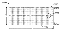
도 1a는 결합제(310) 내에 분산되어 있는 보이드 네트워크 또는 복수의 상호연결된 보이드(320) 및 복수의 입자(340)를 포함하는 경사 광학 필름(300A)의 개략 측면도이다. 경사 광학 필름(300A)은 경사 광학 필름(300A) 내에 보이드 네트워크(network of voids)(320)가 존재하는 것에 의해 다공성 내부를 가진다. 일반적으로, 경사 광학 필름(300A)은 하나 이상의 상호연결된 공극 또는 보이드 네트워크를 포함할 수 있다. 예를 들어, 보이드(320)의 네트워크는 상호연결된 보이드 또는 공극(320A 내지 320C)을 포함하는 것으로 간주될 수 있다.FIG. 1A is a schematic side view of a tilted
어떤 경우에, 국소 모폴로지, 예를 들어, 상호연결된 보이드(370A)의 제1 국소 체적 분율 및 상호연결된 보이드(375A)의 제2 체적 분율이 경사 광학 필름(300A) 내에서 두께 t1 방향("z" 방향이라고도 함)을 따라 변할 수 있다. 도 1a에서, 예를 들어, 상호연결된 보이드(370A)의 제1 국소 체적 분율이 상호연결된 보이드(375A)의 제2 체적 분율보다 큰 것으로 나타내어져 있다. 상호연결된 보이드의 국소 체적 분율 및 공극-크기 분포가 몇가지 방식으로 - 예를 들어, "(경사 나노보이드 물품에 대한 제조방법(Process for Gradient Nanovoided Article)"(미국 출원 제61/254674호; 대리인 사건 번호 65766US002); 및 "경사 저굴절률 물품 및 방법(Gradient Low Index Article and Method)"(미국 출원 제61/254673호; 대리인 사건 번호 65716US002)에 기술되어 있음 - 두께 방향을 따라 변할 수 있다.In some cases, a local morphology, for example, a first local volume fraction of
어떤 경우에, 상호연결된 보이드의 국소 체적 분율[예를 들어, 상호연결된 보이드(372)의 제3 국소 체적 분율, 상호연결된 보이드(374)의 제4 국소 체적 분율, 및 상호연결된 보이드(376)의 제5 국소 체적 분율]이 경사 광학 필름(300A) 내에서의 횡단면 "L"의 방향을 따라(즉, 일반적으로 "x" 및/또는 "y" 방향을 따라) 변할 수 있다. 도 1a에서, 예를 들어, 상호연결된 보이드(376)의 제5 국소 체적 분율이 상호연결된 보이드(372)의 제3 국소 체적 분율 또는 상호연결된 보이드(374)의 제4 국소 체적 분율보다 큰 것으로 나타내어져 있다. 상호연결된 보이드의 국소 체적 분율 및 보이드 크기 분포가 또한 몇가지 방식으로 두께 방향을 따라 변할 수 있으며, 이에 대해서는 다른 곳에서 기술한다. 어떤 경우에, 경사 광학 필름은 다공성 필름 - 보이드 네트워크(320)가 각각 제1 주 표면(330)과 제2 주 표면(332) 사이에 하나 이상의 통로를 형성한다는 것을 의미함 - 이다. 어떤 경우에, 상호연결된 보이드의 국소 체적 분율이"x", "y", 및 "z" 방향의 임의의 조합을 따라 변할 수 있다.In some cases, a local volume fraction of interconnected voids (eg, a third local volume fraction of
보이드의 네트워크는 복수의 상호연결된 보이드를 포함하는 것으로 간주될 수 있다. 보이드 중 일부는 경사 광학 필름의 표면에 있을 수 있고, 표면 보이드(surface void)인 것으로 간주될 수 있다. 예를 들어, 예시적인 경사 광학 필름(300A)에서, 보이드(320D, 320E)는 경사 광학 필름의 제2 주 표면(332)에 있고, 표면 보이드(320D, 320E)인 것으로 간주될 수 있으며, 보이드(320F, 320G)는 경사 광학 필름의 제1 주 표면(330)에 있고, 표면 보이드(320F, 320G)인 것으로 간주될 수 있다. 예를 들어, 보이드(320B, 320C)와 같은 보이드의 일부는 경사 광학 필름의 내부에서 경사 광학 필름의 외측 표면으로부터 먼쪽에 있으며, 내부 보이드(interior void)(320B, 320C)로서 간주될 수 있지만, 내부 보이드가, 예를 들어, 다른 보이드를 통해 주 표면에 연결되어 있을 수 있다.A network of voids may be considered to comprise a plurality of interconnected voids. Some of the voids may be on the surface of the oblique optical film and may be considered to be surface voids. For example, in the exemplary oblique
보이드(320)는 일반적으로 적당한 조성물 및 제조 기법(다양한 코팅, 건조 및 경화 조건 등)을 선택함으로써 제어될 수 있는 크기 d1을 가진다. 일반적으로, d1은 임의의 원하는 범위의 값 중 임의의 원하는 값일 수 있다. 예를 들어, 일부 경우에, 적어도 대다수의 보이드, 예를 들어, 60% 또는 70% 또는 80% 또는 90% 또는 95% 이상의 보이드가 원하는 범위 내의 크기를 갖는다. 예를 들어, 일부 경우에, 적어도 대다수의 보이드, 예를 들어, 60% 또는 70% 또는 80% 또는 90% 또는 95% 이상의 보이드가 약 10 마이크로미터 이하, 또는 약 7 마이크로미터 이하, 또는 약 5 마이크로미터 이하, 또는 약 4 마이크로미터 이하, 또는 약 3 마이크로미터 이하, 또는 약 2 마이크로미터 이하, 또는 약 1 마이크로미터 이하, 또는 약 0.7 마이크로미터 이하, 또는 약 0.5 마이크로미터 이하의 크기를 갖는다.The
일부 경우에, 복수의 상호연결된 보이드(320)는 평균 보이드 또는 기공 크기가 약 5 마이크로미터 이하, 또는 약 4 마이크로미터 이하, 또는 약 3 마이크로미터 이하, 또는 약 2 마이크로미터 이하, 또는 약 1 마이크로미터 이하, 또는 약 0.7 마이크로미터 이하, 또는 약 0.5 마이크로미터 이하이다.In some cases, the plurality of
일부 경우에, 일부 보이드는 충분히 작아서 그의 주요 광학 효과가 유효 굴절률을 감소시키는 것일 수 있는 한편, 일부 다른 보이드는 유효 굴절률 및 산란광을 감소시킬 수 있고, 한편 일부 또 다른 보이드는 충분히 커서 그의 주요 광학 효과가 광을 산란시키는 것일 수 있다.In some cases, some voids may be small enough so that their primary optical effect is to reduce the effective refractive index, while some other voids may reduce the effective refractive index and scattered light, while some other voids are large enough to have their main optical effect. May be to scatter light.
입자(340)는 임의의 원하는 범위의 값 중 임의의 원하는 값일 수 있는 크기 d2를 갖는다. 예를 들어, 어떤 경우에, 적어도 입자의 대부분(적어도 입자의 60% 또는 70% 또는 80% 또는 90% 또는 95% 등)는 원하는 범위에 있는 크기를 가진다. 예를 들어, 어떤 경우에, 적어도 입자의 대부분(적어도 입자의 60% 또는 70% 또는 80% 또는 90% 또는 95% 등)은 약 5 마이크로미터 이하, 또는 약 3 마이크로미터 이하, 또는 약 2 마이크로미터 이하, 또는 약 1 마이크로미터 이하, 또는 약 700 ㎚ 이하, 또는 약 500 ㎚ 이하, 또는 약 200 ㎚ 이하, 또는 약 100 ㎚ 이하, 또는 약 50 ㎚ 이하 또는 심지어 약 20 ㎚ 이하인 크기를 가진다.
일부 경우에, 복수의 입자(340)는 평균 입자 크기가 약 5 마이크로미터 이하, 또는 약 3 마이크로미터 이하, 또는 약 2 마이크로미터 이하, 또는 약 1 마이크로미터 이하, 또는 약 700 ㎚ 이하, 또는 약 500 ㎚ 이하, 또는 약 200 ㎚ 이하, 또는 약 100 ㎚ 이하, 또는 약 50 ㎚ 이하이다.In some cases, the plurality of
어떤 경우에, 입자의 일부는 유효 굴절률에 주로 영향을 미치도록 충분히 작을 수 있고, 다른 일부 입자는 유효 굴절률 및 산란광에 영향을 줄 수 있으며, 또 다른 어떤 입자는 그의 주된 광학 효과가 광을 산란시키는 것이도록 충분히 클 수 있다.In some cases, some of the particles may be small enough to mainly affect the effective refractive index, some other particles may affect the effective refractive index and scattered light, and some other particles may have their main optical effect scattering light. Can be large enough to be.
어떤 경우에, d1 및/또는 d2는 보이드 및 입자의 주된 광학 효과가 경사 광학 필름(300A)의 유효 굴절률에 영향을 주는 것이도록 충분히 작다. 예를 들어, 그러한 경우에, d1 및/또는 d2는 약 λ/5 이하, 또는 약 λ/6 이하, 또는 약 λ/8 이하, 또는 약 λ/10 이하, 또는 약 λ/20 이하이고, 여기서, λ는 광의 파장이다. 다른 예로서, 그러한 경우에, d1 및 d2는 약 70 ㎚ 이하, 또는 약 60 ㎚ 이하, 또는 약 50 ㎚ 이하, 또는 약 40 ㎚ 이하, 또는 약 30 ㎚ 이하, 또는 약 20 ㎚ 이하, 또는 약 10 ㎚이하이다. 이러한 경우에, 보이드 및 입자는 또한 광을 산란시킬 수 있지만, 보이드 및 입자의 주된 광학 효과는 유효 굴절률을 갖는 경사 광학 필름에서의 효과적인 매질을 정의하는 것이다. 유효 굴절률은, 부분적으로, 보이드, 결합제 및 입자의 굴절률에 따라 좌우된다. 일부 경우에, 유효 굴절률은 감소된 유효 굴절률이며, 이는 유효 굴절률이 결합제의 굴절률 및 입자의 굴절률보다 작음을 의미한다.In some cases, d 1 and / or d 2 are small enough that the main optical effects of the voids and particles affect the effective refractive index of the oblique
보이드 및/또는 입자의 주요 광학 효과가 굴절률에 영향을 주는 것인 경우에, d1 및 d2는 충분히 작아서 상당한 분율, 예를 들어, 약 60% 이상, 또는 약 70% 이상, 또는 약 80% 이상, 또는 약 90% 이상, 또는 약 95% 이상의 보이드(320) 및 입자(340)가 유효 굴절률을 감소시키는 주요 광학 효과를 갖는다. 그러한 경우에, 상당한 분율, 예를 들어, 약 60% 이상, 또는 약 70% 이상, 또는 약 80% 이상, 또는 약 90% 이상, 또는 약 95% 이상의 보이드 및/또는 입자가 약 1 ㎚ 내지 약 200 ㎚, 또는 약 1 ㎚ 내지 약 150 ㎚, 또는 약 1 ㎚ 내지 약 100 ㎚, 또는 약 1 ㎚ 내지 약 50 ㎚, 또는 약 1 ㎚ 내지 약 20 ㎚ 범위의 크기를 갖는다.If the main optical effect of the voids and / or particles is to affect the refractive index, d 1 and d 2 are sufficiently small that a significant fraction, for example at least about 60%, or at least about 70%, or about 80% At least, or at least about 90%, or at least about 95%, voids 320 and
일부 경우에, 입자(340)의 굴절률 n1은 결합제(310)의 굴절률 nb에 충분히 근접할 수 있어서, 유효 굴절률이 입자의 굴절률에 따라 좌우되지 않거나 매우 적게 좌우된다. 그러한 경우에, n1 및 nb 사이의 차이는 약 0.01 이하, 또는 약 0.007 이하, 또는 약 0.005 이하, 또는 약 0.003 이하, 또는 약 0.002 이하, 또는 약 0.001 이하이다. 일부 경우에는, 입자(340)가 충분히 작고 그의 굴절률이 결합제의 굴절률에 충분히 근접하여, 입자는 광을 주로 산란시키거나 굴절률에 영향을 주지 않는다. 이러한 경우에, 입자의 주된 효과는, 예를 들어, 경사 광학 필름(300A)의 강도를 향상시키는 것일 수 있다. 어떤 경우에, 입자(340)가 경사 광학 필름을 제조하는 방법을 향상시킬 수 있지만, 경사 광학 필름(300A)이 입자 없이 제조될 수 있다.In some cases, the refractive index n 1 of
보이드 네트워크(320) 및 입자(340)의 주된 광학 효과가, 예를 들어, 광을 산란시키는 것이 아니라 유효 굴절률에 영향을 주는 것인 경우, 보이드(320) 및 입자(340)로 인한 경사 광학 필름(300A)의 광학 탁도는 약 5% 이하, 또는 약 4% 이하, 또는 약 3.5% 이하, 또는 약 4% 이하, 또는 약 3% 이하, 또는 약 2.5% 이하, 또는 약 2% 이하, 또는 약 1.5% 이하, 또는 약 1% 이하이다. 이러한 경우에, 경사 광학 필름의 효과적인 매질의 유효 굴절률은 약 1.35 이하, 또는 약 1.3 이하, 또는 약 1.25 이하, 또는 약 1.2 이하, 또는 약 1.15 이하, 또는 약 1.1 이하, 또는 약 1.05 이하이다.Oblique optical film due to void 320 and
경사 광학 필름(300A)이 적절하게도 감소된 유효 굴절률을 가질 수 있는 경우에, 경사 광학 필름의 두께는 약 100 ㎚ 이상, 또는 약 200 ㎚ 이상, 또는 약 500 ㎚ 이상, 또는 약 700 ㎚ 이상, 또는 약 1,000 ㎚ 이상, 또는 약 1500 ㎚ 이상, 또는 약 2000 ㎚ 이상이다.In the case where the oblique
일부 경우에, d1 및/또는 d2는 충분히 커서 그의 주요 광학 효과가 광을 산란시키고 광학 탁도를 제공하는 것이다. 그러한 경우에, d1 및/또는 d2는 약 200 ㎚ 이상, 또는 약 300 ㎚ 이상, 또는 약 400 ㎚ 이상, 또는 약 500 ㎚ 이상, 또는 약 600 ㎚ 이상, 또는 약 700 ㎚ 이상, 또는 약 800 ㎚ 이상, 또는 약 900 ㎚ 이상, 또는 약 1000 ㎚ 이상이다. 이러한 경우에, 보이드 및 입자는 또한 굴절률에 영향을 줄 수 있지만, 종종 그의 주된 광학 효과는 광을 산란시키는 것이다. 이러한 경우에, 경사 광학 필름에 입사하는 광은 보이드 및 입자 둘 다에 의해 산란될 수 있다.In some cases, d 1 and / or d 2 are sufficiently large that their main optical effects scatter light and provide optical haze. In such cases, d 1 and / or d 2 is at least about 200 nm, or at least about 300 nm, or at least about 400 nm, or at least about 500 nm, or at least about 600 nm, or at least about 700 nm, or about 800 At least nm, or at least about 900 nm, or at least about 1000 nm. In this case, voids and particles can also affect the refractive index, but often their main optical effect is to scatter light. In this case, light incident on the oblique optical film can be scattered by both voids and particles.
경사 광학 필름(300A)이 많은 광학 응용에서 사용될 수 있다. 예를 들어, 어떤 경우에, 경사 광학 필름은 내부 전반사(TIR)를 지원 또는 증진하거나 내부 반사를 향상시키는 데 사용될 수 있고, 이는 그 반사가 굴절률 nb를 갖는 물질이 일으키는 것보다 더 많다는 것을 의미한다. 이러한 경우에, 경사 광학 필름의 표면에서 내부 전반사를 겪는 광선의 소산 테일(evanescent tail)이 경사 광학 필름의 두께에 걸쳐 광 결합하지 않거나 거의 광 결합하지 않거나 심지어 제어가능하게 결합되도록 경사 광학 필름(300A)이 충분히 두껍다. 이러한 경우에, 경사 광학 필름(300A)의 두께 t1은 약 1 마이크로미터 이상, 또는 약 1.1 마이크로미터 이상, 또는 약 1.2 마이크로미터 이상, 또는 약 1.3 마이크로미터 이상, 또는 약 1.4 마이크로미터 이상, 또는 약 1.5 마이크로미터 이상, 또는 약 1.7 마이크로미터 이상, 또는 약 2 마이크로미터 이상이다. 충분히 두꺼운 경사 광학 필름(300A)은 경사 광학 필름의 두께에 걸쳐 광학 모드의 소산 테일의 원하지 않는 광 결합을 방지하거나 감소시킬 수 있다. 경사 광학 필름의 TIR 특성이 횡단면을 따라 필름의 상이한 영역에서 변할 수 있으며, 이에 대해서는 다른 곳에서 기술한다.Inclined
어떤 경우에, 경사 광학 필름(300A)의 일부분이 낮은 광학 탁도를 가진다. 이러한 경우에, 경사 광학 필름의 광학 탁도는 약 5% 이하, 또는 약 4% 이하, 또는 약 3.5% 이하, 또는 약 4% 이하, 또는 약 3% 이하, 또는 약 2.5% 이하, 또는 약 2% 이하, 또는 약 1.5% 이하, 또는 약 1% 이하이다. 이러한 경우에, 경사 광학 필름은 약 1.35 이하, 또는 약 1.3 이하, 또는 약 1.2 이하, 또는 약 1.15 이하, 또는 약 1.1 이하, 또는 약 1.05 이하인 감소된 유효 굴절률을 가진다. 경사 광학 필름(300A)에 수직 입사하는 광의 경우, 광학 탁도는, 본 명세서에서 사용되는 바와 같이, 총 투과 광에 대한 수직 방향으로부터 4도 초과만큼 벗어난 투과 광의 비로서 정의된다. 본 명세서에 개시된 탁도 값은 ASTM D1003에 기술된 절차에 따라 Haze-Gard Plus 탁도계(미국 메릴랜드주 실버 스프링 소재의 BYK-Gardner)를 사용하여 측정되었다. 경사 광학 필름의 탁도 특성이 횡단면을 따라 필름의 상이한 영역에서 변할 수 있으며, 이에 대해서는 다른 곳에서 기술한다.In some cases, a portion of the oblique
어떤 경우에, 경사 광학 필름(300A)의 일부분이 높은 광학 탁도를 가진다. 이러한 경우에, 경사 광학 필름의 탁도는 약 40% 이상, 또는 약 50% 이상, 또는 약 60% 이상, 또는 약 70% 이상, 또는 약 80% 이상, 또는 약 90% 이상, 또는 약 95% 이상이다. 어떤 경우에, 경사 광학 필름(300A)은 중간 광학 탁도, 예를 들어, 약 5% 내지 약 50% 광학 탁도를 가질 수 있다.In some cases, a portion of the oblique
어떤 경우에, 경사 광학 필름(300A)의 일부분은 높은 확산 광 반사율을 가진다. 이러한 경우에, 경사 광학 필름의 확산 광 반사율은 약 30% 이상, 또는 약 40% 이상, 또는 약 50% 이상, 또는 약 60% 이상이다. 경사 광학 필름의 확산 광 반사율이 횡단면을 따라 필름의 상이한 영역에서 변할 수 있으며, 이에 대해서는 다른 곳에서 기술한다.In some cases, a portion of the oblique
어떤 경우에, 경사 광학 필름(300A)의 일부분이 높은 광학 투명도를 가진다. 경사 광학 필름(300A)에 수직 입사하는 광의 경우, 광학 투명도는, 본 명세서에서 사용되는 바와 같이, 비 (T2-T1)/(T1+T2)를 말하고, 여기서 T1은 수직 방향으로부터 1.6 내지 2 도만큼 벗어나는 투과 광이고, T2는 수직 방향으로부터 0 내지 0.7 도 사이에 있는 투과 광이다. 본 명세서에 개시된 투명도 값은 BYK-Gardner의 Haze-Gard Plus 탁도계를 사용하여 측정되었다. 경사 광학 필름(300A)이 높은 광학 투명도를 가지는 경우에, 투명도는 약 40% 이상, 또는 약 50% 이상, 또는 약 60% 이상, 또는 약 70% 이상, 또는 약 80% 이상, 또는 약 90% 이상, 또는 약 95% 이상이다. 경사 광학 필름의 광학 투명도가 횡단면을 따라 필름의 상이한 영역에서 변할 수 있으며, 이에 대해서는 다른 곳에서 기술한다.In some cases, a portion of the oblique
어떤 경우에, 경사 광학 필름(300A)의 일부분이 낮은 광학 투명도를 가진다. 이러한 경우에, 경사 광학 필름의 광학 투명도는 약 40% 이하, 또는 약 20% 이하, 또는 약 10% 이하, 또는 약 7% 이하, 또는 약 5% 이하, 또는 약 4% 이하, 또는 약 3% 이하, 또는 약 2% 이하, 또는 약 1% 이하이다.In some cases, a portion of the oblique
일반적으로, 경사 광학 필름은 응용에서 바람직할 수 있는 임의의 공극률, 공극-크기 분포 또는 보이드 체적 분율을 가질 수 있다. 어떤 경우에, 경사 광학 필름(300A) 내의 복수의 보이드(320)의 체적 분율은 약 20% 이상, 또는 약 30% 이상, 또는 약 40% 이상, 또는 약 50% 이상, 또는 약 60% 이상, 또는 약 70% 이상, 또는 약 80% 이상, 또는 약 90% 이상이다.In general, the oblique optical film may have any porosity, pore-size distribution or void volume fraction that may be desirable in an application. In some cases, the volume fraction of the plurality of
어떤 경우에, 경사 광학 필름이 높은 광학 탁도 및/또는 확산 반사율을 가질지라도, 경사 광학 필름의 일부분이 어떤 저굴절률 특성을 나타낼 수 있다. 예를 들어, 이러한 경우에, 경사 광학 필름의 일부분이 결합제(310)의 굴절률 nb보다 작은 굴절률에 대응하는 각도에서 TIR을 지원할 수 있다.In some cases, even if the oblique optical film has high optical haze and / or diffuse reflectance, a portion of the oblique optical film may exhibit some low refractive index characteristics. For example, in this case, a portion of the oblique optical film may support the TIR at an angle that corresponds to a refractive index less than the refractive index n b of the
예시적인 경사 광학 필름(300A)에서, 입자(340A, 340B)와 같은 입자(340)는 중실 입자이다. 어떤 경우에, 경사 광학 필름(300A)은 그에 부가하여 또는 대안적으로 복수의 중공 또는 다공성 입자(350)를 포함할 수 있다.In the exemplary oblique
입자(340)는 일정 응용에 바람직할 수 있는 임의의 유형의 입자일 수 있다. 예를 들어, 입자(340)는 유기 또는 무기 입자일 수 있다. 예를 들어, 입자(340)는 실리카, 산화지르코늄 또는 알루미나 입자일 수 있다.
입자(340)는 일정 응용에 바람직하거나 이용가능할 수 있는 임의의 형상을 가질 수 있다. 예를 들어, 입자(340)는 규칙적이거나 불규칙적인 형상을 가질 수 있다. 예를 들어, 입자(340)는 거의 구형일 수 있다. 다른 일례로서, 입자가 길 수 있다. 이러한 경우에, 경사 광학 필름(300A)은 복수의 긴 입자(340)를 포함한다. 어떤 경우에, 긴 입자는 약 1.5 이상, 또는 약 2 이상, 또는 약 2.5 이상, 또는 약 3 이상, 또는 약 3.5 이상, 또는 약 4 이상, 또는 약 4.5 이상, 또는 약 5 이상인 평균 종횡비를 가진다. 어떤 경우에, 입자는 진주 목걸이(미국 텍사스주 휴스턴 소재의 Nissan Chemical로부터 입수가능한 Snowtex-PS 입자 등) 또는 구형이나 비결정성 입자의 응집 사슬(aggregated chain)(건식 실리카 등)의 형태 또는 형상으로 되어 있을 수 있다.
입자(340)는 작용화될 수 있거나 작용화되지 않을 수 있다. 일부 경우에, 입자(340)는 작용화되지 않는다. 일부 경우에, 입자(340)는 클럼핑(clumping)이 없이 또는 매우 적은 클럼핑을 가지고 원하는 용매 또는 결합제(310) 중에 분산될 수 있도록 작용화된다. 일부 경우에, 입자(340)는 결합제(310)에 화학적으로 결합하도록 추가로 작용화될 수 있다. 예를 들어, 입자(340A)와 같은 입자(340)는 표면 개질될 수 있으며 결합제(310)에 화학적으로 결합하는 반응성 작용기 또는 기(360)를 가질 수 있다. 그러한 경우에, 적어도 상당한 분율의 입자(340)가 결합제에 화학적으로 결합된다. 일부 경우에, 입자(340)는 결합제(310)에 화학적으로 결합하는 반응성 작용기를 갖지 않는다. 이러한 경우에, 입자(340)는 결합제(310)에 물리적으로 결합될 수 있거나, 결합제(310)가 입자(340)를 캡슐화시킬 수 있다.
어떤 경우에, 일부 입자는 반응성 기를 가지고, 다른 입자는 반응성 기를 갖지 않는다. 예를 들어, 일부 경우에, 약 10%의 입자는 반응성 기를 가지고 약 90%의 입자는 반응성 기를 갖지 않거나, 또는 약 15%의 입자는 반응성 기를 가지고 약 85%의 입자는 반응성 기를 갖지 않거나, 또는 약 20%의 입자는 반응성 기를 가지고 약 80%의 입자는 반응성 기를 갖지 않거나, 또는 약 25%의 입자는 반응성 기를 가지고 약 75%의 입자는 반응성 기를 갖지 않거나, 또는 약 30%의 입자는 반응성 기를 가지고 약 60%의 입자는 반응성 기를 갖지 않거나, 또는 약 35%의 입자는 반응성 기를 가지고 약 65%의 입자는 반응성 기를 갖지 않거나, 또는 약 40%의 입자는 반응성 기를 가지고 약 60%의 입자는 반응성 기를 갖지 않거나, 또는 약 45%의 입자는 반응성 기를 가지고 약 55%의 입자는 반응성 기를 갖지 않거나, 또는 약 50%의 입자는 반응성 기를 가지고 약 50%의 입자는 반응성 기를 갖지 않는다. 어떤 경우에, 입자의 일부는 동일한 입자 상의 반응성 기 및 비반응성 기 둘다에 의해 작용기화될 수 있다.In some cases, some particles have reactive groups and others do not have reactive groups. For example, in some cases, about 10% of the particles have reactive groups and about 90% of the particles have no reactive groups, or about 15% of the particles have reactive groups and about 85% of the particles have no reactive groups, or About 20% of the particles have reactive groups and about 80% of the particles have no reactive groups, or about 25% of the particles have reactive groups and about 75% of the particles have no reactive groups, or about 30% of the particles have reactive groups About 60% of the particles have no reactive groups, or about 35% of the particles have reactive groups and about 65% of the particles have no reactive groups, or about 40% of the particles have reactive groups and about 60% of the particles are reactive No groups, or about 45% of the particles have reactive groups and about 55% of the particles have no reactive groups, or about 50% of the particles have reactive groups and about 50% of the particles are reactive It does not have a group. In some cases, some of the particles may be functionalized by both reactive and non-reactive groups on the same particle.
입자의 앙상블(ensemble)이 여러 크기, 반응성 및 비반응성 입자와 상이한 유형의 입자 - 예를 들어, 아크릴, 폴리카보네이트, 폴리스티렌, 실리콘 등과 같은 중합체성 입자를 포함하는 유기 입자; 또는, 예를 들어, 실리카 및 지르코늄 산화물 등을 포함하는 유리 또는 세라믹과 같은 무기 입자 - 의 혼합물을 포함할 수 있다.Particles of a different type from which the ensemble of particles differs from particles of various sizes, reactive and non-reactive-organic particles including polymeric particles such as, for example, acrylic, polycarbonate, polystyrene, silicone and the like; Or inorganic particles such as glass or ceramics, including, for example, silica and zirconium oxide, and the like.
결합제(310)는 일정 응용에 바람직할 수 있는 임의의 물질일 수 있거나 그를 포함할 수 있다. 예를 들어, 결합제(310)는 가교 결합된 중합체와 같은 중합체를 형성하는 경화성 물질일 수 있다. 일반적으로, 결합제(310)는 임의의 중합성 물질 - UV 경화성 물질과 같은 방사선 경화성인 중합성 물질 등 - 일 수 있다.The
경사 광학 필름(300A)은 응용에 바람직할 수 있는 임의의 방법을 사용하여 제조될 수 있다. 어떤 경우에, 경사 광학 필름(300A)은 발명의 명칭이 "나노보이드 물품에 대한 제조방법 및 장치(PROCESS AND APPARATUS FOR A NANOVOIDED ARTICLE)"인 동시 계류 중인 출원(미국 출원 제61/169429호; 대리인 사건 번호 65046US002), 발명의 명칭이 "감소된 결함을 갖는 코팅에 대한 제조방법 및 장치(PROCESS AND APPARATUS FOR COATING WITH REDUCED DEFECTS)"인 동시 계류 중인 출원(미국 출원 제61/169427호; 대리인 사건 번호 65185US002), 및 발명의 명칭이 "경사 나노보이드 물품에 대한 제조방법(PROCESS FOR GRADIENT NANOVOIDED ARTICLE)"인 동시 계류 중인 출원(미국 출원 제61/254674호; 대리인 사건 번호 65766US002) - 이들의 개시 내용은 참조 문헌으로서 그 전체 내용이 본 명세서에 포함됨 - 에 기술된 방법에 의해 제조될 수 있다.Tilt
일반적으로, 전형적으로 본 명세서에서 "GEL" 제조방법이라고 하는 한 방법에서, 먼저 복수의 입자(나노입자 등) 및 용매에 용해되어 있는 중합성 물질을 포함하는 용액이 준비되고, 여기서 중합성 물질은, 예를 들어, 하나 이상의 유형의 단량체를 포함할 수 있다. 그 다음, 예를 들어, 열 또는 광을 인가해 중합성 물질을 중합하여, 용매 중에 불용성 중합체 매트릭스를 형성한다. 중합이 일어남에 따라, (경화된 매트릭스에서의) 용매 용해성이 감소되고 매트릭스로부터 상분리(phase separate)될 수 있다. 이 결과, 매트릭스가 많은 네트워크 및 상분리된 용매가 많은 네트워크가 얻어진다. 용매가 나중에 제거되고, 다공성 코팅을 생성하는 공극 및 보이드를 남긴다. 필름의 모폴로지 및 토포그라피를 결정하는 데 상분리의 정도 및 유형이 주된 요인이다. 최종적인 구조물이 또한 매트릭스 네트워크의 기계적 특성에 의존한다. 용매가 제거될 때 보이드 공간을 유지시키도록 네트워크 탄성 계수(modulus) 및 강도가 충분해야만 한다. 모폴로지를 결정하는 데 조성물 및 경화의 정도가 요인이다.Generally, in one method, typically referred to herein as a "GEL" manufacturing method, a solution is prepared that first comprises a plurality of particles (such as nanoparticles) and a polymerizable material dissolved in a solvent, wherein the polymerizable material is For example, one or more types of monomers. Then, for example, heat or light is applied to polymerize the polymerizable material to form an insoluble polymer matrix in a solvent. As the polymerization takes place, solvent solubility (in the cured matrix) may be reduced and phase separate from the matrix. As a result, a network rich in matrix and a network rich in phase separated solvents are obtained. The solvent is later removed, leaving voids and voids creating a porous coating. The extent and type of phase separation is a major factor in determining the morphology and topography of the film. The final structure also depends on the mechanical properties of the matrix network. The network modulus and strength must be sufficient to maintain the void space when the solvent is removed. The degree of composition and cure is a factor in determining morphology.
중합, 건조 및 경화 환경을 제어함으로써, 모폴로지가 제어될 수 있다. 이 방법은 또한 코팅 스테이션과 중합 장치 사이의 제어된 환경 영역을 이용할 수 있고, 이에 대해서는 다른 곳에서 기술한다. 이 영역은 코팅된 필름 조성물 및 환경의 향상된 제어를 가능하게 해준다. 중합 장치는 코팅 스테이션과 건조기 사이의 아무 곳이나 위치될 수 있다. 중합화 동안 환경을 제어하는 것도 유리하다. 중합된 코팅은 이어서 건조되고, 물질을 추가로 경화시키기 위해, 예를 들어, 종래의 UV)방사 시스템을 사용하여 추가로 후처리될 수 있다. 중합 장치에서 사용될 수 있는 방사원은 LED, UV 레이저, UV 램프, 및 전자빔을 포함한다.By controlling the polymerization, drying and curing environment, the morphology can be controlled. The method may also utilize a controlled environmental area between the coating station and the polymerization apparatus, which is described elsewhere. This area allows for improved control of the coated film composition and environment. The polymerization apparatus can be located anywhere between the coating station and the dryer. It is also advantageous to control the environment during the polymerization. The polymerized coating can then be dried and further post-treated using, for example, conventional UV) spinning systems to further cure the material. Radiation sources that can be used in the polymerization apparatus include LEDs, UV lasers, UV lamps, and electron beams.
일부 경우에, 중합 단계 후에, 용매는 중합성 물질의 일부를 더 낮은 농도지만 여전히 포함할 수 있다. 그 다음에, 용액을 건조시키거나 증발시킴으로써 용매가 제거되고, 그 결과 중합체 결합제(310)에 분산되어 있는 복수의 보이드 또는 보이드 네트워크(320)를 포함하는 경사 광학 필름(300A)이 얻어진다. 경사 광학 필름은 중합체에 분산되어 있는 복수의 입자(340)를 추가로 포함한다. 입자가 결합제에 결합되거나 - 여기서 결합은 물리적 또는 화학적임 -, 결합제에 의해 캡슐화되어 있을 수 있다.In some cases, after the polymerization step, the solvent may still contain a lower concentration of a portion of the polymerizable material. The solvent is then removed by drying or evaporating the solution, resulting in a gradient
경사 광학 필름(300A)은, 결합제(310) 및 입자(340)에 부가하여, 다른 물질을 가질 수 있다. 예를 들어, 경사 광학 필름(300A)은, 경사 광학 필름이 형성되는 기재(도 1에 명확히 도시되지 않음)의 표면을 웨팅시키는 것을 돕기 위해, 하나 이상의 첨가제(예를 들어, 커플링제 등)를 포함할 수 있다. 다른 일례로서, 경사 광학 필름(300A)은 경사 광학 필름에 색상(검정색 등)을 부여하기 위해 하나 이상의 착색제(카본 블랙 등)를 포함할 수 있다. 경사 광학 필름(300A) 내의 다른 예시적인 물질은 개시제(하나 이상의 광개시제 등); 정전기 방지제(anti-stat); 점착 촉진제; 계면 활성제; UV 흡수제; 이형제; 또는 다른 것을 포함하며, 이에 대해서는 다른 곳에서 기술한다. 어떤 경우에, 경사 광학 필름(300A)은 광을 흡수하고 더 긴 파장의 광을 재방출할 수 있는 하향 변환 물질을 포함할 수 있다. 예시적인 하향 변환 물질에는 인광체(phosphor)가 포함된다.The tilted
일반적으로, 경사 광학 필름(300A)은 결합제(310) 대 복수의 입자(340)의 임의의 중량비에 대해 일정 범위의 바람직한 공극률을 가질 수 있다. 따라서, 일반적으로, 중량비는 일정 응용에 바람직할 수 있는 임의의 값일 수 있다. 일부 경우에, 결합제(310) 대 복수의 입자(340)의 중량비는 약 1:2.5 이상, 또는 약 1:2.3 이상, 또는 약 1:2 이상, 또는 약 1:1 이상, 또는 약 1.5:1 이상, 또는 약 2:1 이상, 또는 약 2.5:1 이상, 또는 약 3:1 이상, 또는 약 3.5:1 이상, 또는 약 4:1 이상, 또는 약 5:1 이상이다. 일부 경우에, 중량비는 약 1:2.3 내지 약 4:1의 범위이다.In general, the gradient
어떤 경우에, 경사 광학 필름(300A)의 상부 주 표면(332)이, 예를 들어, 경사 광학 필름의 다른 층에 대한 점착력을 향상시키기 위해, 처리될 수 있다. 예를 들어, 상부 표면은 코로나 처리될 수 있다.In some cases, the upper
도 1b 내지 도 1i는, 각각, 본 개시 내용의 상이한 태양에 따른, 경사 광학 필름(300B-300I)의 개략 평면도이다. 명확함을 위해, 도 1a에 대해 기술된 번호가 매겨진 요소(310 내지 360) 및 크기 d1 내지 d3는 도 1b 내지 도 1i에는 도시되어 있지 않지만, 도 1a의 경사 광학 필름(300A)에 대해 제공된 각각의 설명이 또한 도 1b 내지 도 1i의 경사 광학 필름(300B 내지 300G)에, 각각, 대응한다. 도 1a 내지 도 1i에 나타낸 바와 같이, 두께에 따라 변하는 경사 광학 필름을 생성하는 기술들 중 임의의 기술이 또한 (필름의 표면에 평행인) 횡단면에 걸쳐 변하는 경사 광학 필름과 관련해서도 사용될 수 있다는 것을 잘 알 것이다. 두께 경사의 변동에 대한 기술이, 예를 들어, 발명의 명칭이 "PROCESS FOR GRADIENT NANOVOIDED ARTICLE"인 동시 계류 중인 출원(미국 출원 제61/254674호; 대리인 사건 번호 65766US002)에 기술되어 있다.1B-1I are schematic plan views of the gradient
한 특정의 실시 형태에서, 횡단면 변동을 갖는 경사 광학 필름은, 예를 들어, 인접 영역의 근방에서의 중합 개시제 농도의 차이 또는 중합 억제제 농도의 차이를 사용하여 생성될 수 있다. 한 특정의 실시 형태에서, 중합 광의 강도가 인접 영역의 근방에서 감소되도록, 새도우 마스크가 램프와 코팅 사이에 위치될 수 있다. 한 특정의 실시 형태에서, 방사의 강도가 코팅의 폭에 걸쳐 시간적으로 또는 공간적으로 변화될 수 있고, 이는 국소 모폴로지에 영향을 미칠 수 있으며, 이에 대해서는 다른 곳에서 기술한다. 한 특정의 실시 형태에서, 예를 들어, 영역이 상이한 중합체 결합제 대 입자의 비를 포함하는 경우에, 다층 코팅 기술이 사용될 수 있다.In one particular embodiment, the oblique optical film having a cross sectional variation can be produced using, for example, a difference in polymerization initiator concentration or difference in polymerization inhibitor concentration in the vicinity of an adjacent region. In one particular embodiment, a shadow mask can be positioned between the lamp and the coating so that the intensity of the polymerized light is reduced in the vicinity of the adjacent region. In one particular embodiment, the intensity of the radiation can vary either temporally or spatially over the width of the coating, which can affect the local morphology, which is described elsewhere. In one particular embodiment, multilayer coating techniques can be used, for example, where the regions comprise a ratio of different polymer binders to particles.
경사 구조물을 부여하는 데 몇가지 기술 - 예를 들어, 선량을 수정하는 기술; 용매 수정 기술; 화학적, 코팅 및 외부 기술; 그리고 당업자에게 안출될 수 있는 다른 기술을 포함함 - 이 사용될 수 있다. 선량을 수정하는 기술은, 예를 들어, 시간적 수정(LED를 펄스화하는 것), LED 레이저 기입, 상이한 파장의 광원의 제어, 및 비디오 영상(웨브와 함께 움직임)을 포함하는 광원 기술; 새도우 마스크, 그레이스케일 마스크 및 내부에 광원을 갖는 투명한 롤 내부에 있는 마스크를 포함하는 마스크 기술; 및 웨브 속도 변동, 거리 또는 광의 초점의 변동을 포함하는 기계 기술. 용매 수정 기술은, 예를 들어, 온도 경사; 진공, 흐름, 마스킹된 건조, 및 가스의 포화도를 포함하는 부등 건조 기술; 및 다른 패턴의 스트라이프(stripe)로 코팅하는 것을 비롯한 용매 코팅 기술을 포함한다. 화학적 기술은, 예를 들어, 화학적 첨가제, 가스 및 산소 억제(oxygen inhibition)를 포함하는 패턴화된 광 개시제 및 패턴화된 광 억제제를 포함한다. 코팅 기술은, 예를 들어, 스트라이프 코팅 및 패턴 오버코팅을 포함한다. 외부 기술은, 예를 들어, 인가된 장(예를 들어, 전기장 또는 자기장, 기타 등등)를 포함한다.Several techniques for imparting sloped structures, for example techniques for modifying dose; Solvent modification techniques; Chemical, coating and external technologies; And other techniques that can be devised to those skilled in the art-may be used. Techniques for dose modification include, for example, light source techniques including temporal correction (pulsing LEDs), LED laser writing, control of light sources of different wavelengths, and video images (moving with the web); Mask techniques including a shadow mask, a grayscale mask and a mask inside a transparent roll having a light source therein; And a variation in web speed, variation in distance or focus of light. Solvent modification techniques include, for example, temperature gradients; Unequal drying techniques including vacuum, flow, masked drying, and saturation of the gas; And solvent coating techniques, including coating with stripes of other patterns. Chemical techniques include, for example, patterned photoinitiators and chemical patterned photoinhibitors including chemical additives, gas and oxygen inhibition. Coating techniques include, for example, stripe coating and pattern overcoating. External techniques include, for example, applied fields (eg, electric or magnetic fields, etc.).
일반적으로, 예를 들어, 글자, 단어, 심볼 또는 심지어 그림 등의 표식을 포함하는 임의의 원하는 패턴이 기재된 기술들의 조합에 의해 발생될 수 있다. 패턴이 또한 연속적, 불연속적, 단조적, S자형, 임의의 매끄럽게 변하는 함수; 스트라이프; 기계 방향, 가로 방향, 또는 둘 다에서 변하는 것일 수 있고; 경사가 이미지, 로고, 또는 텍스트를 형성할 수 있으며; 이들이 패턴화된 코팅 및/또는 구멍을 포함할 수 있다.In general, any desired pattern can be generated by a combination of the described techniques, including, for example, markers such as letters, words, symbols or even pictures. The pattern is also a continuous, discontinuous, monotonous, sigmoidal, any smoothly varying function; stripe; May vary in machine direction, transverse direction, or both; The slope may form an image, logo, or text; These may include patterned coatings and / or holes.
도 1b에서, 경사 광학 필름(300B)은 횡단면 LW를 정의하는 길이 L 및 폭 W를 포함한다. 경사 광학 필름(300B)은 또한 횡단면 LW를 따라, 예를 들어, 도시된 바와 같이, 단조적으로 변하는 국소 모폴로지(390B)를 포함한다. 한 특정의 실시 형태에서, 경사 광학 필름(300B)의 제1 에지(330B)의 근방에서의 상호연결된 보이드(370B)의 제1 국소 체적 분율은 경사 광학 필름(300B)의 제2 에지(332B)의 근방에서의 상호연결된 보이드(375B)의 제2 국소 체적 분율보다 낮고, 에지들 사이에서 단조적으로 변한다. 경사 광학 필름(300B)이 각종의 기술을 사용하여 준비될 수 있으며, 이에 대해서는 다른 곳에서 기술한다.In FIG. 1B, the oblique
도 1c에서, 경사 광학 필름(300C)은 횡단면 LW를 정의하는 길이 L 및 폭 W를 포함한다. 경사 광학 필름(300C)은 또한 횡단면 LW를 따라, 예를 들어, 도시된 바와 같이, 단계적으로 변하는 국소 모폴로지(390C)를 포함한다. 한 특정의 실시 형태에서, 경사 광학 필름(300C)의 제1 에지(330C)의 근방에서의 상호연결된 보이드(370C)의 제1 국소 체적 분율은 경사 광학 필름(300C)의 제2 에지(332C)의 근방에서의 상호연결된 보이드(375C)의 제2 국소 체적 분율보다 낮다. 어떤 경우에, 예를 들어, 도 1c에 도시된 바와 같이, 상호연결된 보이드(370C)의 제1 국소 체적 분율이 상호연결된 보이드(375C)의 제2 국소 체적 분율로 급격하게(즉, 단계적으로) 천이한다. 어떤 경우에, 상호연결된 보이드(375C)의 제2 체적 분율의 선폭 d1은 폭 W의 작은 비율, 예를 들어, 총 폭 W의 약 1% 내지 약 5%, 또는 약 1% 내지 약 10%, 또는 약 1% 내지 약 20%, 또는 약 1% 내지 약 30% 또는 그 이상일 수 있다. 기술 분야의 당업자에게는 명백한 바와 같이, 상호연결된 보이드(370C)의 제1 국소 체적 분율을 갖는 다수의 영역이 경사 광학 필름(300C)의 폭 W에 걸쳐 형성될 수 있다. 경사 광학 필름(300C)이 각종의 기술을 사용하여 준비될 수 있으며, 이에 대해서는 다른 곳에서 기술한다.In FIG. 1C, the oblique
도 1d에서, 경사 광학 필름(300D)은 횡단면 LW를 정의하는 길이 L 및 폭 W를 포함한다. 경사 광학 필름(300D)은 또한 횡단면 LW를 따라 변하는, 예를 들어, 도시된 바와 같이, 상호연결된 보이드(377D)의 최소 국소 체적 분율을 가지는 국소 모폴로지(390C)를 포함한다. 한 특정의 실시 형태에서, 경사 광학 필름(300D)의 제1 에지(330D)의 근방에서의 상호연결된 보이드(370D)의 제1 국소 체적 분율은 경사 광학 필름(300D)의 제2 에지(332D)의 근방에서의 상호연결된 보이드(375D)의 제2 국소 체적 분율과 대략 동일하다. 어떤 경우에, 예를 들어, 도 1d에 도시된 바와 같이, 상호연결된 보이드(370D)의 제1 국소 체적 분율이 상호연결된 보이드(377D)의 최소 국소 체적 분율로 급격하게(즉, 단계적으로) 천이된다. 어떤 경우에, 천이가 단계적 변화에서와 같이 급격할 수 있거나, 천이가 약간 원만할 수 있다[예를 들어, "S"자형 천이(도시 생략)]. 어떤 경우에, 상호연결된 보이드(377D)의 최소 체적 분율의 선폭 d1은 폭 W의 작은 비율, 예를 들어, 폭 W의 약 1% 내지 약 5%, 또는 약 1% 내지 약 10%, 또는 약 1% 내지 약 20%, 또는 약 1% 내지 약 30% 또는 그 이상일 수 있다. 어떤 경우에, 상호연결된 보이드(377D)의 최소 국소 체적 분율의 상대적 위치가 폭 W에 걸쳐 다수의 위치에서 아무 곳에나 위치될 수 있다. 경사 광학 필름(300D)이 각종의 기술을 사용하여 준비될 수 있으며, 이에 대해서는 다른 곳에서 기술한다.In FIG. 1D, the oblique
도 1e에서, 경사 광학 필름은 횡단면 LW를 정의하는 길이 L 및 폭 W를 포함한다. 경사 광학 필름(300E)은 또한 횡단면 LW를 따라 변하는, 예를 들어, 도시된 바와 같이, 제1 및 제2 에지(330E, 332E)의 근방에서 상호연결된 보이드의 단계적 변화 국소 체적 분율을 가지는 국소 모폴로지(390E)를 포함한다. 한 특정의 실시 형태에서, 경사 광학 필름(300E)의 제1 에지(330E)의 근방에서의 상호연결된 보이드(370E)의 제1 국소 체적 분율은 경사 광학 필름(300E)의 제2 에지(332E)의 근방에서의 상호연결된 보이드(375E)의 제2 국소 체적 분율과 대략 동일하다. 어떤 경우에, 예를 들어, 도 1e에 도시된 바와 같이, 상호연결된 보이드(370E)의 제1 국소 체적 분율이 상호연결된 보이드(377E)의 최대 국소 체적 분율로 급격하게(즉, 단계적으로) 천이된다. 어떤 경우에, 상호연결된 보이드(370E, 375E)의 제1 및 제2 국소 체적 분율 각각은 단계적이 아닌 천이를 가질 수 있다(도시되어 있지 않지만, 도 1b에 도시된 단조적 변동과 유사함). 경사 광학 필름(300E)이 각종의 기술을 사용하여 준비될 수 있으며, 이에 대해서는 다른 곳에서 기술한다.In FIG. 1E, the oblique optical film comprises a length L and a width W defining a cross section LW. Gradient
도 1f에서, 경사 광학 필름(300F)은 횡단면 LW를 정의하는 길이 L 및 폭 W를 포함한다. 경사 광학 필름(300F)은 또한 횡단면 LW를 따라 변하는, 예를 들어, 도시된 바와 같이, 상호연결된 보이드(377F)의 경사 최소 국소 체적 분율을 가지는 국소 모폴로지(390F)를 포함한다. 한 특정의 실시 형태에서, 경사 광학 필름(300F)의 제1 에지(330F)의 근방에서의 상호연결된 보이드(370F)의 제1 국소 체적 분율은 경사 광학 필름(300F)의 제2 에지(332F)의 근방에서의 상호연결된 보이드(375F)의 제2 국소 체적 분율과 대략 동일하다. 어떤 경우에, 예를 들어, 도 1f에 도시된 바와 같이, 상호연결된 보이드(370F)의 제1 국소 체적 분율이 상호연결된 보이드(377F)의 최소 국소 체적 분율로 점진적으로(즉, 단조 경사로) 천이되고, 상호연결된 보이드(375F)의 제2 체적 분율로 다시 점진적으로 천이된다. 경사 광학 필름(300F)이 각종의 기술을 사용하여 준비될 수 있으며, 이에 대해서는 다른 곳에서 기술한다.In FIG. 1F, the oblique
도 1g에서, 경사 광학 필름(300G)은 횡단면 LW를 정의하는 길이 L 및 폭 W를 포함한다. 경사 광학 필름(300G)은 또한 횡단면 LW를 따라 변하는, 예를 들어, 도시된 바와 같이, 상호연결된 보이드(377G, 378G)의 한쌍의 단계적 변화 국소 체적 분율을 가지는 국소 모폴로지(390G)를 포함한다. 한 특정의 실시 형태에서, 경사 광학 필름(300G)의 제1 에지(330G)의 근방에서의 상호연결된 보이드(370G)의 제1 국소 체적 분율은 경사 광학 필름(300G)의 제2 에지(332G)의 근방에서의 상호연결된 보이드(375G)의 제2 국소 체적 분율과 대략 동일하다. 어떤 경우에, 예를 들어, 도 1g에 도시된 바와 같이, 상호연결된 보이드(370G)의 제1 국소 체적 분율이 상호연결된 보이드(377G)의 최소 국소 체적 분율로 급격하게(즉, 단계적으로) 천이되고, 상호연결된 보이드(380G)의 최대 국소 체적 분율로 다시 급격하게 천이되며, 상호연결된 보이드(378G)의 최소 국소 체적 분율로 다시 급격하게 천이되고, 마지막으로 상호연결된 보이드(375G)의 제2 국소 체적 분율로 또다시 급격하게 천이된다. 어떤 경우에, 상호연결된 보이드의 국소 체적 분율 각각은 단계적이 아닌 천이를 가질 수 있다(도시되어 있지 않지만, 도 1b에 도시된 단조적 변동과 유사함). 경사 광학 필름(300G)이 각종의 기술을 사용하여 준비될 수 있으며, 이에 대해서는 다른 곳에서 기술한다.In FIG. 1G, the oblique
도 1h에서, 경사 광학 필름(300H)은 횡단면 LW를 정의하는 길이 L 및 폭 W를 포함한다. 경사 광학 필름(300H)은 또한 횡단면 LW를 따라 변하는, 예를 들어, 도시된 바와 같이, 경사 광학 필름(300H)의 길이 L을 따라 변하는 상호연결된 보이드(380H, 382H)의 단계적 변화 국소 체적 분율을 가지는 국소 모폴로지(390H)를 포함한다. 한 특정의 실시 형태에서, 상호연결된 보이드(380H)의 제1 국소 체적 분율은 경사 광학 필름(300G)의 제1 에지(330H) 및 제2 에지(332H) 둘 다에 수직이고, 상호연결된 보이드(382H)의 제2 국소 체적 분율도 역시 경사 광학 필름(300G)의 제1 및 제2 에지(330H, 332H)에 수직이다. 어떤 경우에, 예를 들어, 도 1h에 도시된 바와 같이, 상호연결된 보이드(380H)의 제1 국소 체적 분율이 상호연결된 보이드(382H)의 최소 국소 체적 분율로 급격하게(즉, 단계적으로) 천이되고, 경사 광학 필름의 길이 L을 따라 유사한 방식으로 계속된다. 어떤 경우에, 상호연결된 보이드의 국소 체적 분율 각각은 단계적이 아닌 천이를 가질 수 있다(도시되어 있지 않지만, 도 1b에 도시된 단조적 변동과 유사함). 경사 광학 필름(300H)이 각종의 기술을 사용하여 준비될 수 있으며, 이에 대해서는 다른 곳에서 기술한다.In FIG. 1H, the oblique
도 1i에서, 경사 광학 필름(300I)은 횡단면 LW를 정의하는 길이 L 및 폭 W를 포함한다. 경사 광학 필름(300I)은 또한 횡단면 LW를 따라 변하는, 예를 들어, 도시된 바와 같이, 바둑판 방식으로 변하는 상호연결된 보이드(380I, 382I)의 단계적 변화 국소 체적 분율을 가지는 국소 모폴로지(390I)를 포함한다. 예를 들어, 기하 형상, 단어, 표식, 이미지 등을 포함하는 임의의 원하는 패턴이 횡단면에 걸쳐 형성될 수 있다는 것을 잘 알 것이다. 한 특정의 실시 형태에서, 예를 들어, 도 1i에 도시된 바와 같이, 상호연결된 보이드(380I)의 제1 국소 체적 분율이 상호연결된 보이드(382I)의 최소 국소 체적 분율로 급격하게(즉, 단계적으로) 천이되고, 경사 광학 필름의 횡단면 LW에 걸쳐 유사한 방식으로 계속된다. 어떤 경우에, 상호연결된 보이드의 국소 체적 분율 각각은 단계적이 아닌 천이를 가질 수 있다(도시되어 있지 않지만, 도 1b에 도시된 단조적 변동과 유사함). 경사 광학 필름(300I)이 각종의 기술을 사용하여 준비될 수 있으며, 이에 대해서는 다른 곳에서 기술한다.In FIG. 1I, the oblique optical film 300I includes a length L and a width W that define a cross section LW. The oblique optical film 300I also includes a local morphology 390I having a gradual change local volume fraction of interconnected voids 380I, 382I that vary along the cross-section LW, for example, in a checkered manner, as shown. do. It will be appreciated that any desired pattern can be formed over a cross section, including, for example, geometric shapes, words, markers, images, and the like. In one particular embodiment, for example, as shown in FIG. 1I, the first local volume fraction of interconnected voids 380I is abruptly (ie, stepwise) at the minimum local volume fraction of interconnected voids 382I. ) And continue in a similar manner across the cross-section LW of the oblique optical film. In some cases, each of the local volume fractions of interconnected voids may have a non-step transition (similar to the monotonic variation shown in FIG. 1B, though not shown). Inclined optical film 300I may be prepared using various techniques, which are described elsewhere.
도 2는 기재(610) 상에 배치된 경사 광학 필름(630)을 포함하는 광학 구조체(600)의 개략 측면도이다. 어떤 경우에, 기재(610)는 전사가능한 경사 광학 필름(630)을 제공하는 이형 라이너이고, 이는, 예를 들어, 경사 광학 필름(630)의 노출된 상부 주 표면(632)이 기재 또는 표면과 접촉하게 위치될 수 있고 그 후에 이형 라이너가 경사 광학 필름으로부터 박리되어, 예를 들어, 다른 기재 또는 표면에 접합될 수 있는 경사 광학 필름의 하부 주 표면(634)을 노출시킬 수 있다는 것을 의미한다. 이형 라이너(610)로부터 저굴절률 층(630)을 이형하기 위한 이형력은 일반적으로 약 0.19 N/㎝(75 gf/인치) 미만, 또는 약 0.29 N/㎝(100 gf/인치) 미만, 또는 약 0.39 N/㎝(150 gf/인치) 미만, 또는 약 0.58 N/㎝(200 gf/인치) 미만, 또는 약 0.77 N/㎝(50 gf/인치) 미만이다.2 is a schematic side view of an
경사 광학 필름(630)이 본 명세서에 개시된 임의의 경사 광학 필름과 유사할 수 있다. 예를 들어, 경사 광학 필름(630)은 경사 광학 필름(300A 내지 300I) 중 하나와 유사할 수 있다. 어떤 경우에, 경사 광학 필름(630)은 다수의 층을 포함할 수 있고, 하나 이상의 층이 경사 광학 필름(300A 내지 300I) 중 하나와 유사하거나, 하나 이상의 층이, 다른 곳에서 기술하는 바와 같이, "z" 경사 필름을 포함하거나, 하나 이상의 층이 비경사 필름, 또는 경사 필름과 비경사 필름의 조합을 포함한다. 어떤 경우에, 경사 광학 필름(300A 내지 300I) 중 하나가 기재(610) 상에 직접 코팅될 수 있다. 어떤 경우에, 경사 광학 필름(300A 내지 300I) 중 하나가 먼저 형성되고 그 후에 기재(610) 상으로 전사될 수 있다. 기재(610)는 반투명, 투명 또는 불투명일 수 있다.The tilting
기재(610)는 유전체, 반도체, 또는 도체(금속 등)와 같은, 응용에 적당할 수 있는 임의의 물질일 수 있거나 이를 포함할 수 있다. 예를 들어, 기재(610)는 유리 및 중합체, 예를 들어, 폴리에틸렌 테레프탈레이트(PET), 폴리카르보네이트, 및 아크릴을 포함할 수 있거나 그로 제조될 수 있다. 어떤 경우에, 기재(610)는 반사 편광기, 흡수 편광기, 와이어 격자 편광기, 또는 광섬유 편광기 등의 편광기를 포함할 수 있다. 어떤 경우에, 기재(610)는, 예를 들어, 다층 반사 필름 및 다층 편광 필름을 포함한 다층 광학 필름 등의 다수의 층을 포함할 수 있다. 어떤 경우에, 기재(610)는, 예를 들어, BEF(Brightness Enhancing Film) 등의 V자 홈, 재귀반사체 등의 큐브-코너(cube-corner), 또는 기술 분야에 공지된 다른 미세구조물을 포함하는 복수의 미세구조물을 갖는 표면 등의 구조화된 표면을 포함할 수 있다. 어떤 경우에, 기재(610)는, 예를 들어, 프라이머 코팅(primer coating) 또는 접착제 코팅 등의 추가의 코팅을 주 표면 상에 포함할 수 있다.
본 명세서에서 사용되는 바와 같이, 광섬유 편광기는 결합제 내에 매립되어 있는 하나 이상의 광섬유 층을 형성하는 복수의 실질적으로 평행한 광섬유를 포함하고, 여기서 결합제 및 광섬유 중 적어도 하나가 복굴절 물질을 포함한다. 실질적으로 평행한 광섬유는 투과축 및 반사축을 정의한다. 광섬유 편광기는 투과축에 평행하게 편광되어 있는 입사광을 실질적으로 투과시키고, 반사축에 평행하게 편광되어 있는 입사광을 실질적으로 반사시킨다. 광섬유 편광기의 일례는, 예를 들어, 미국 특허 제7,599,592호 및 제7,526,164호에 기술되어 있으며, 이들 특허는 참조 문헌으로서 그 전체 내용이 본 명세서에 포함된다.As used herein, an optical fiber polarizer includes a plurality of substantially parallel optical fibers forming one or more optical fiber layers embedded in a binder, wherein at least one of the binder and the optical fiber comprises a birefringent material. Substantially parallel optical fibers define the transmission axis and the reflection axis. The optical fiber polarizer substantially transmits incident light polarized parallel to the transmission axis, and substantially reflects incident light polarized parallel to the reflection axis. Examples of optical fiber polarizers are described, for example, in US Pat. Nos. 7,599,592 and 7,526,164, which are incorporated herein by reference in their entirety.
어떤 경우에, 기재(610)는 부분 반사체를 포함할 수 있다. 부분 반사체는 입사광의 적어도 30%를 반사시키는 반면 흡수 손실을 뺀 나머지를 투과시키는 하나의 광학 요소 또는 광학 요소의 집합체이다. 적당한 부분 반사체는, 예를 들어, 발포체, 편광 및 비편광 다층 광학 필름, 미세복제 구조물(예를 들어, BEF), 편광된 및 비편광된 블렌드, 와이어 격자 편광기, 부분 투과성 금속(은 또는 니켈 등), 금속/유전체 적층물(은 및 인듐 주석 산화물 등), 및 비대칭 광학 필름을 포함한다. 비대칭 광학 필름은, 예를 들어, 미국 특허 제6,924,014호(Ouderkirk 등)에, 또한 PCT 공개 WO2008/144636에 기술되어 있다. 또한, 예를 들어, 유공(perforating) ESR(3M Company로부터 입수가능함) 등의 유공(perforated) 부분 반사체 또는 거울이 부분 반사체로서 유용하다.In some cases,
한 특정의 실시 형태에서, 기재(610)는 반사 편광기일 수 있다. 반사 편광기 층은 제1 편광 상태를 가지는 광을 실질적으로 반사시키고, 제2 편광 상태를 가지는 광을 실질적으로 투과시키며, 여기서 2개의 편광 상태는 상호 직교이다. 예를 들어, 반사 편광기에 의해 실질적으로 반사되는 편광 상태에 대한 가시광에서의 반사 편광기의 평균 반사율은 적어도 약 50%, 또는 적어도 약 60%, 또는 적어도 약 70%, 또는 적어도 약 80%, 또는 적어도 약 90%, 또는 적어도 약 95%이다. 다른 일례로서, 반사 편광기에 의해 실질적으로 투과되는 편광 상태에 대한 가시광에서의 반사 편광기의 평균 투과율은 적어도 약 50%, 또는 적어도 약 60%, 또는 적어도 약 70%, 또는 적어도 약 80%, 또는 적어도 약 90%, 또는 적어도 약 95%, 또는 적어도 약 97%, 또는 적어도 약 98%, 또는 적어도 약 99%이다. 어떤 경우에, 반사 편광기는 제1 선형 편광 상태를 가지는(예를 들어, x-방향을 따르는) 광을 실질적으로 반사시키고, 제2 선형 편광 상태를 가지는(예를 들어, z-방향을 따르는) 광을 실질적으로 투과시킨다.In one particular embodiment, the
예를 들어, Vikuiti™ DBEF(Dual Brightness Enhancement Film) 등의 MOF(multilayer optical film) 반사 편광기, 미국 미네소타주 세인트 폴 소재의 3M Company로부터 입수가능한 Vikuiti™ DRPF(Diffuse Reflective Polarizer Film) 등의 연속상 및 분산상을 가지는 DRPF(diffusely reflective polarizing film), 예를 들어, 미국 특허 제6,719,426호에 기술된 와이어 격자 반사 편광기, 또는 콜레스테릭 반사 편광기와 같은 임의의 적당한 유형의 반사 편광기가 사용될 수 있다.Continuous phases such as, for example, multi-layer optical film (MOF) reflective polarizers such as Vikuiti ™ Dual Brightness Enhancement Film (DBEF), and Vikuiti ™ Diffuse Reflective Polarizer Film (DRPF) available from 3M Company, St. Paul, Minn. Any suitable type of reflective polarizer may be used, such as a diffusely reflective polarizing film (DRPF) having a dispersed phase, for example, a wire grating reflective polarizer described in US Pat. No. 6,719,426, or a cholesteric reflective polarizer.
예를 들어, 어떤 경우에, 반사 편광기 층은 상이한 중합체 물질의 교번하는 층으로 이루어진 MOF 반사 편광기일 수 있거나 이를 포함할 수 있고, 여기서 교번하는 층 세트들 중 하나의 세트가 복굴절 물질로 이루어져 있고, 상이한 물질의 굴절률이 하나의 선형 편광 상태로 편광된 광에 대해서는 정합되고 직교 선형 편광 상태의 광에 대해서는 정합되지 않는다. 이러한 경우에, 정합된 편광 상태에 있는 입사광은 반사 편광기를 통해 실질적으로 투과되고, 비정합된 편광 상태에 있는 입사광은 반사 편광기에 의해 실질적으로 반사된다. 어떤 경우에, MOF 반사 편광기는 무기 유전체층의 적층물을 포함할 수 있다.For example, in some cases, the reflective polarizer layer may be or include a MOF reflective polarizer composed of alternating layers of different polymeric materials, wherein one set of alternating layer sets is comprised of birefringent materials, The refractive indices of the different materials are matched for light polarized in one linear polarization state and not for light in an orthogonal linear polarization state. In this case, incident light in the matched polarization state is substantially transmitted through the reflective polarizer, and incident light in the mismatched polarization state is substantially reflected by the reflective polarizer. In some cases, the MOF reflective polarizer may comprise a stack of inorganic dielectric layers.
다른 일례로서, 반사 편광기는 통과 상태(pass state)에서 중간의 축상 평균 반사율을 가지는 부분 반사층일 수 있거나 이를 포함할 수 있다. 예를 들어, 부분 반사층은 xy-평면과 같은 제1 평면에서 편광된 가시광에 대해 적어도 약 90%의 축상 평균 반사율, 및 제1 평면에 수직인 제2 평면(xz-평면 등)에서 편광된 가시광에 대해 약 25% 내지 약 90% 범위의 축상 평균 반사율을 가질 수 있다. 이러한 부분 반사층은, 예를 들어, 미국 특허 공개 제2008/064133호(참조 문헌으로서 그 전체 내용이 본 명세서에 포함됨)에 기술되어 있다.As another example, the reflective polarizer may be or include a partially reflective layer having an intermediate on-axis average reflectance in a pass state. For example, the partial reflecting layer may have an axial mean reflectance of at least about 90% for visible light polarized in the first plane, such as the xy-plane, and visible light polarized in the second plane (xz-plane, etc.) perpendicular to the first plane. For on-axis average reflectance in the range of about 25% to about 90%. Such partially reflective layers are described, for example, in US Patent Publication No. 2008/064133 (incorporated herein by reference in its entirety).
어떤 경우에, 반사 편광기는 원형 반사 편광기일 수 있거나 이를 포함할 수 있고, 여기서 시계 방향 또는 반시계 방향일 수 있는 한 방향으로 원형 편광된 광(우회전 또는 좌회전 원편광이라고도 함)이 우선적으로 투과되고, 반대 방향으로 편광된 광이 우선적으로 반사된다. 한 유형의 원형 편광기는 콜레스테릭 액정 편광기를 포함한다.In some cases, the reflective polarizer may be or include a circular reflective polarizer, where circularly polarized light (also referred to as right turn or left turn circularly polarized light) is preferentially transmitted in one direction, which may be clockwise or counterclockwise. , The light polarized in the opposite direction is preferentially reflected. One type of circular polarizer includes a cholesteric liquid crystal polarizer.
어떤 경우에, 반사 편광기는 2008년 11월 19일자로 출원된 미국 가특허 출원 제61/116132호, 2008년 11월 19일자로 출원된 미국 가특허 출원 제61/116291호, 2008년 11월 19일자로 출원된 미국 가특허 출원 제61/116294호, 2008년 11월 19일자로 출원된 미국 가특허 출원 제61/116295호, 2008년 11월 19일자로 출원된 미국 가특허 출원 제61/116295호, 및 2007년 5월 20일자로 출원된 미국 가특허 출원 제60/939085호를 기초로 우선권을 주장하는, 2008년 5월 19일자로 출원된 국제 특허 출원 제PCT/US 2008/060311호(이들 모두는 참조 문헌으로서 그 전체 내용이 본 명세서에 포함됨)에 기술된 것과 같은, 광 간섭에 의해 광을 반사시키거나 투과시키는 다층 광학 필름일 수 있다.In some cases, the reflective polarizer is US Provisional Patent Application 61/116132, filed November 19, 2008, US Provisional Patent Application 61/116291, filed November 19, 2008, 19 November 2008. United States Provisional Patent Application 61/116294, filed November 19, 2008 United States Provisional Patent Application 61/116295, filed November 19, 2008, United States Provisional Patent Application 61/116295, filed November 19, 2008 And International Patent Application No. PCT / US 2008/060311, filed May 19, 2008, which claims priority based on US Provisional Patent Application No. 60/939085, filed May 20, 2007 ( All of these may be multilayer optical films that reflect or transmit light by light interference, such as those described in the entirety of which is incorporated herein by reference.
한 특정의 실시 형태에서, 기재(610)는 프리즘 모양의 광 방향 전환 필름 등의 미세구조화된 표면일 수 있다.예를 들어, 경사 광학 필름(630)이 3M Company로부터 입수가능한 Vikuiti™ BEF(Brightness Enhancing Film) 등의 광 방향 전환 필름의 프리즘측에 코팅될 수 있다. BEF는, 예를 들어, 24 마이크로미터 피치 및 약 90도의 프리즘 피크각 또는 정각을 갖는 복수의 선형 프리즘을 포함한다. 기술 분야의 당업자에게 공지되어 있는 바와 같이, 경사 광학 필름(630)이 컨포멀 코팅(conformal coating), 평탄화된 코팅(planarized coating), 또는 코팅된 패턴으로서 미세구조화된 표면 상에 코팅될 수 있다.In one particular embodiment, the
광학 구조체(600)에서의 2개의 이웃하는 주 표면 각각의 상당 부분이 경사 광학 필름(630)의 하부 주 표면(634)을 따라 서로 물리적 접촉을 하고 있다. 예를 들어, 2개의 이웃하는 주 표면들의 50% 이상, 또는 60% 이상, 또는 70% 이상, 또는 80% 이상, 또는 90% 이상, 또는 95%가 서로 물리적으로 접촉해 있다. 예를 들어, 어떤 경우에, 경사 광학 필름(630)은 기재(610) 바로 위에 코팅되어 있다.A substantial portion of each of two neighboring major surfaces in the
도 3은 기재(710) 상에 배치된 경사 광학 필름(730), 및 경사 광학 필름(730) 상에 배치된 광학 접착제층(720)을 포함하는 광학 구조체(700)의 개략 측면도이다. 기재(710)는, 예를 들어, 도 2를 참조하여 기술된 기재(610) 등의 기재를 비롯하여, 다른 곳에서 기술된 기재들 중 임의의 기재일 수 있다. 어떤 경우에, 광학 접착제층(720)은 경사 광학 필름(730)의 보이드의 침투를 억제하는 밀봉제로서 기능할 수 있다. 어떤 경우에, 기재(710)의 대향하는 측면 상에 광학 접착제층(720) 및 경사 광학 필름(730)을 갖는 것이 바람직할 수 있다. 다른 경우에, 기재(710)의 양 측면 상에 경사 광학 필름(730)을 갖는 것이 바람직할 수 있다.3 is a schematic side view of an
광학 접착제 층(720)은 일정 응용에 바람직하고/바람직하거나 이용가능할 수 있는 임의의 광학 접착제일 수 있다. 예를 들어, 접착제층이 시간이 지남에 따라 또는 날씨에 노출 시에 황변되어 접착제 및 경사 광학 필름의 광학 성능을 열화시키지 않도록 광학 접착제층(720)이 충분한 광학 품질 및 광 안정성을 갖는다. 일부 경우에, 광학 접착제 층(720)은 실질적으로 투명한 광학 접착제일 수 있으며, 이는 접착제 층이 높은 경면 투과율(specular transmittance) 및 낮은 확산 투과율을 가짐을 의미한다. 예를 들어, 이러한 경우에, 광학 접착제층(720)의 경면 투과율(specular transmittance)은 약 70% 이상, 또는 약 80% 이상, 또는 약 90% 이상, 또는 약 95% 이상이다.Optical
어떤 경우에, 광학 접착제층(720)은 실질적으로 광 확산성이 있고, 이는 접착제층이 높은 확산 투과율 및 낮은 경면 투과율을 가지며, 광학 접착제층(720)이 백색 외관을 가질 수 있다는 것을 의미한다. 예를 들어, 이러한 경우에, 광 확산성 접착제 층(720)의 광학 탁도는 약 30% 이상, 약 30% 이상, 또는 약 50% 이상, 또는 약 60% 이상, 또는 약 70% 이상, 또는 약 80% 이상, 또는 약 90% 이상, 또는 약 95% 이상이다. 어떤 경우에, 확산성 접착제 층의 확산 반사율은 약 20% 이상, 또는 약 30% 이상, 또는 약 40% 이상, 또는 약 50% 이상, 또는 약 60% 이상이다. 이러한 경우에, 접착제 층은 광학 접착제에 분산되어 있는 복수의 입자를 포함함으로써 광 확산성이 있을 수 있고, 여기서 입자 및 광학 접착제는 상이한 굴절률을 가진다. 2개의 굴절률 사이의 부정합으로 인해 광 산란이 일어날 수 있다.In some cases, the optical
예시적인 광학 접착제에는 감압 접착제(PSA), 감열 접착제, 용매-휘발성 접착제, 재배치가능한 접착제(repositionable adhesive) 또는 재가공가능한 접착제(reworkable adhesive), 및 UV-경화성 접착제, 예를 들어, 노어랜드 프로덕츠, 인크.(Norland Products, Inc.)로부터 입수가능한 UV-경화성 광학 접착제가 포함된다.Exemplary optical adhesives include pressure sensitive adhesives (PSAs), thermal adhesives, solvent-volatile adhesives, repositionable adhesives or reworkable adhesives, and UV-curable adhesives such as Norland Products, Inc. UV-curable optical adhesives available from Norland Products, Inc. are included.
예시적인 PSA는 천연 고무, 합성 고무, 스티렌 블록 공중합체, (메트)아크릴 블록 공중합체, 폴리비닐 에테르, 폴리올레핀, 및 폴리(메트)아크릴레이트를 기재로 한 것들을 포함한다. 본 명세서에 사용되는 바와 같이, (메트)아크릴 (또는 아크릴레이트)는 아크릴 화학종 및 메타크릴 화학종 둘 모두를 말한다. 다른 예시적인 PSA는 (메트)아크릴레이트, 고무, 열가소성 탄성중합체, 실리콘, 우레탄, 및 이들의 조합을 포함한다. 일부 경우에, PSA는 (메트)아크릴 PSA 또는 적어도 하나의 폴리(메트)아크릴레이트를 기재로 한다. 예시적인 실리콘 PSA는 중합체 또는 검(gum) 및 선택적인 점착성 부여 수지를 포함한다. 다른 예시적인 실리콘 PSA는 폴리다이오르가노실록산 폴리옥사미드 및 선택적인 점착성 부여제를 포함한다.Exemplary PSAs include those based on natural rubber, synthetic rubber, styrene block copolymers, (meth) acrylic block copolymers, polyvinyl ethers, polyolefins, and poly (meth) acrylates. As used herein, (meth) acryl (or acrylate) refers to both acrylic species and methacryl species. Other exemplary PSAs include (meth) acrylates, rubbers, thermoplastic elastomers, silicones, urethanes, and combinations thereof. In some cases, the PSA is based on (meth) acrylic PSA or at least one poly (meth) acrylate. Exemplary silicone PSAs include polymers or gums and optional tackifying resins. Other exemplary silicone PSAs include polydiorganosiloxane polyoxamides and optional tackifiers.
경사 광학 필름(730)이 본 명세서에 개시된 임의의 경사 광학 필름과 유사할 수 있다. 예를 들어, 경사 광학 필름(730)은 경사 광학 필름(300A 내지 300I) 중 하나와 유사할 수 있다. 다른 일례로서, 경사 광학 필름(730)은 다수의 층을 포함할 수 있고, 여기서 각각의 층은 경사 광학 필름(300A 내지 300I) 중 하나와 유사하다.The tilted
한 특정의 실시 형태에서, 선택적인 광 확산기(도시 생략)가 광학 접착제층(720) 상에 배치되어, 광 확산기/광학 접착제/경사 광학 필름/기재의 적층물을 형성할 수 있다. 선택적인 광 확산기는 응용에 바람직하고 및/또는 이용가능할 수 있는 임의의 광 확산기를 포함할 수 있다. 예를 들어, 광 확산기는 표면 확산기, 체적 확산기, 또는 그 조합일 수 있거나 이를 포함할 수 있다. 예를 들어, 선택적인 광 확산기는 상이한 굴절률 n2를 갖는 결합제 또는 호스트 매질에 분산되어 있는 제1 굴절률 n1을 갖는 복수의 입자를 포함할 수 있고, 여기서 2개의 굴절률 사이의 차는 적어도 약 0.01, 또는 적어도 약 0.02, 또는 적어도 약 0.03, 또는 적어도 약 0.04, 또는 적어도 약 0.05 이다.In one particular embodiment, an optional light diffuser (not shown) may be disposed on the optical
도 4는 기재(820) 상에 배치된 제1 광학 접착제층(820), 제1 광학 접착제층(820) 상에 배치된 경사 광학 필름(830), 및 경사 광학 필름(830) 상에 배치된 선택적인 제2 광학 접착제층(840)을 포함하는 광학 구조체(800)의 개략 측면도이다. 기재(810)는, 예를 들어, 도 2를 참조하여 기술된 기재(610) 등의 기재를 비롯하여, 다른 곳에서 기술된 기재들 중 임의의 기재일 수 있다. 광학 접착제층(820, 840)은 광학 접착제 층(720)과 유사할 수 있다. 일부 경우에, 광학 접착제 층(820, 840)은 동일한 굴절률을 갖는다. 일부 경우에, 두 접착제 층은 상이한 굴절률을 가질 수 있다.4 shows a first optical
경사 광학 필름(830)이 본 명세서에 개시된 임의의 경사 광학 필름과 유사할 수 있다. 예를 들어, 경사 광학 필름(830)은 경사 광학 필름(300A 내지 300I) 중 하나와 유사할 수 있다. 다른 일례로서, 경사 광학 필름(830)은 다수의 층을 포함할 수 있고, 여기서 각각의 층은 경사 광학 필름(300A 내지 300I) 중 하나와 유사하다.The tilting
도 8은 본 개시 내용의 일 태양에 따른 패턴화된 재귀반사체(900)의 개략 단면도이다. 패턴화된 재귀반사체(900)는 큐브-코너 재귀반사체(920)의 어레이를 갖는 기재(910)를 포함한다. 제1 영역(930)은 큐브-코너 재귀반사체(920)에 인접해 있는 고굴절 물질을 포함한다. 큐브-코너 재귀반사체(920)에 인접해 있는 저굴절률 물질을 포함하는 제2 영역(940)은 제1 영역(930)에 인접해 있다. 제1 및 제2 영역(930, 940)은 다른 곳에서 기술된 방법에 따라 준비되고 패턴화될 수 있는 중합체 경사 필름이다. 안료 코팅(pigmented coating)(950)이 제1 영역(930) 및 제2 영역(940) 상에 배치될 수 있다. 제2 영역(940)에 인접해 있는 큐브-코너 재귀반사체(920)에 입사하는 제1 광선(960)이 도시된 바와 같이 재귀반사된다. 제1 영역(930)에 인접해 있는 큐브-코너 재귀반사체에 입사하는 제2 광선(970)은 재귀반사되지 않고, 그 대신에 제1 영역(930)에 인접해 있는 안료 코팅(950)을 보여준다.8 is a schematic cross-sectional view of a
도 9는 본 개시 내용의 일 태양에 따른 패턴화된 도광체(1000)의 개략 단면도이다. 패턴화된 도광체(1000)는 도광체(1020)에 광을 주입할 수 있는 광원(1010)을 포함한다. 도광체(1020)는 중공 도광체 또는 중실 도광체일 수 있으며, 이에 대해서는 다른 곳에서 기술한다. 도광체(1020)는, 다른 곳에서 기술하는 바와 같이, 제1 영역(1040)이 도광체(1020)의 굴절률보다 낮은 굴절률의 물질을 포함하고 제2 인접 영역(1050)이 도광체(1020)의 굴절률보다 낮지 않은 굴절률을 갖는 물질을 포함하도록 준비될 수 있는 경사 중합체 필름(1030)을 포함한다. 도광체(1020)가 TIR에 의해 광을 전파시킬 수 있기 때문에, 제1 광선(1060)은 제1 영역(1040)에 인접하여 TIR을 겪는 것으로 도시되어 있고, TIR이 제2 영역(1050)에서 좌절되기 때문에, 제2 광선(1070)은 도광체 밖으로 방향 전환되는 것으로 도시되어 있다. 어떤 경우에, 제2 인접 영역(1050)의 굴절률은 도광체(1020)의 굴절률과 본질적으로 동일할 수 있고, 기술 분야의 당업자에게는 공지되어 있는 바와 같이, 제2 광선(1070)은 방향의 변경 없이 도광체를 빠져나갈 수 있다. 기술 분야의 당업자에게는 공지되어 있는 바와 같이, 도광체를 빠져나가는 광을 방향 전환시키기 위해 다양한 추출기 요소가 경사 중합체 필름(1030)의 상부 표면(1080)에 인접하여 위치될 수 있다.9 is a schematic cross-sectional view of a patterned
어떤 경우에, X(다운-웨브), Y(교차-웨브), XY, XZ, YZ, 및 XYZ 경사 조합을 생성하기 위해, 개시된 경사들이 원하는 임의의 방식으로 결합될 수 있다. 경사가 또한 임의의 원하는 표면 패턴화와 결합될 수 있고, 예를 들어, PET, 폴리카보네이트, MOF, 미세복제된 광학 필름 등을 비롯한 상이한 기판에 적용될 수 있다.In some cases, the disclosed slopes can be combined in any manner desired to produce a combination of X (down-web), Y (cross-web), XY, XZ, YZ, and XYZ slopes. Slope can also be combined with any desired surface patterning and can be applied to different substrates including, for example, PET, polycarbonate, MOF, microreplicated optical films, and the like.
어떤 경우에, 기재는 이형 라이너, 접착제, 체적 확산기, 표면 확산기, 회절 확산기, 굴절 확산기, 재귀반사체, 흡수 편광기, 반사 편광기, 광섬유 편광기, 콜레스테릭 편광기, 다층 편광기, 와이어 격자 편광기, 부분 반사체, 체적 반사체, 다층 중합체 반사체, 금속 반사체, 금속/유전체 다층 반사체, 광섬유, 렌즈, 미세구조체, 중실 도광체, 또는 중공 도광체 중 적어도 하나일 수 있다. 어떤 경우에, 미세구조체가 재귀반사체, BEF(brightness enhancing film), 렌즈렛, 이득 확산기, 광 추출 필름, 또는 터닝 필름(turning film)일 수 있다.In some cases, the substrate may be a release liner, adhesive, volume diffuser, surface diffuser, diffractive diffuser, refractive diffuser, retroreflector, absorbing polarizer, reflective polarizer, optical fiber polarizer, cholesteric polarizer, multilayer polarizer, wire lattice polarizer, partial reflector, At least one of a volume reflector, a multilayer polymer reflector, a metal reflector, a metal / dielectric multilayer reflector, an optical fiber, a lens, a microstructure, a solid light guide, or a hollow light guide. In some cases, the microstructures may be retroreflectors, brightness enhancing films (BEFs), lenslets, gain diffusers, light extraction films, or turning films.
어떤 경우에, 경사 중합체 필름은 다수의 층을 포함할 수 있고, 하나 이상의 층이 경사 광학 필름(300A 내지 300I) 중 하나와 유사하거나, 하나 이상의 층이, 다른 곳에서 기술하는 바와 같이, "z" 경사 필름을 포함하거나, 하나 이상의 층이 비경사 필름, 또는 경사 필름과 비경사 필름의 조합을 포함한다. 어떤 경우에, 경사 중합체 필름은 낮은 탁도/높은 탁도/낮은 탁도인 층들의 조합을 포함할 수 있다. 일반적으로 다층 코팅에서의 이러한 다른 층은, 예를 들어, 체적 확산기, 다공성 코팅, 확산 다공성 코팅, 밀봉제, 프라이머, 접착제 등을 포함할 수 있다. 다층 코팅층은 다층 코팅 적층물의 서브표면층(subsurface layer)의 표면층일 수 있다. 일반적으로, 기술 분야의 당업자에게는 공지되어 있는 바와 같이, 다층 코팅이 동시에 또는 순차적으로 생성될 수 있다.In some cases, the gradient polymer film may comprise multiple layers, and one or more layers are similar to one of the gradient
한 특정의 실시 형태에서, 굴절률의 패턴화된 차이를 갖는 경사 광학 필름(graded optical film)이 광 추출에 유용할 수 있다.이러한 경사 광학 필름은, 예를 들어, 도광체로부터 광 방향 전환 요소로의 선택적 투과를 가능하게 해줄 수 있다. 도광체는 도광체의 표면으로부터의 내부 전반사(TIR)로 인해 영역에 거쳐 광을 전파시킨다. 도광체와 주변 매질 사이에 큰 굴절률 차가 있는 경우, TIR이 일어난다. 도광체에 라미네이트되어 있는 유사한 굴절률의 영역과 교대로 있는 저굴절률의 영역을 갖는 경사 광학 필름은 굴절률이 낮은 경우 광이 선택적 TIR을 겪게 할 수 있지만, 더 높은 굴절률의 영역이 있는 경우 광이 도광체를 빠져나갈 수 있게 해줄 수 있다. 전형적으로, 프리즘, 이득 확산기, 터닝 필름, 또는 기술 분야에 공지된 다른 이러한 구조물을 비롯한 광 방향 전환 요소로의 광을 계측하기 위해 이 제어된 추출이 사용될 수 있다. 어떤 경우에, 광 방향 전환 요소는 미세복제된 또는 각도 선택적 MOF일 수 있다.In one particular embodiment, a graded optical film having a patterned difference in refractive index may be useful for light extraction. Such a graded optical film is, for example, from the light guide to the light redirecting element. It can enable selective transmission of. The light guide propagates light through the area due to total internal reflection (TIR) from the surface of the light guide. TIR occurs when there is a large difference in refractive index between the light guide and the surrounding medium. Gradient optical films having regions of low refractive index that alternate with regions of similar refractive index laminated to the light guide may cause light to undergo selective TIR at low refractive indices, but light may be present at higher refractive index regions. It can help you escape. Typically, this controlled extraction can be used to measure light to light redirecting elements, including prisms, gain diffusers, turning films, or other such structures known in the art. In some cases, the light redirecting element can be a microreplicated or angular selective MOF.
개시된 경사 필름은, 예를 들어, 중실 도광체 추출기, 중공(공기) 도광체 추출기, 광섬유 등을 비롯한 도광체 가변 추출기; 예를 들어, 결함 및/또는 전구 은폐에, 특히 백라이트 디스플레이에 유용한 경사 탁도 필름; 가변 확산기; 가변 흡수기; 주광 조명에 대한 ESR(enhanced specular reflector)을 포함하는 가변 반사체 등을 포함하는 응용에서 사용될 수 있다.Disclosed tilted films include, for example, light guide variable extractors, including solid light guide extractors, hollow (air) light guide extractors, optical fibers, and the like; For example, oblique haze films useful for concealing defects and / or bulbs, in particular for backlight displays; Variable diffuser; Variable absorbers; It can be used in applications including variable reflectors and the like including enhanced specular reflectors (ESR) for daylight illumination.
실시예Example
이하의 실시예에서, BYK-Gardner Haze-Gard Plus 탁도계(미국 메릴랜드주 실버 스프링스 소재의 BYK-Gardner로부터 입수가능함)를 사용하여 투과율, 탁도 및 투명도가 측정되었다. 달리 언급하지 않는 한, 모든 화학 물질이 미국 위스콘신주 밀워키 소재의 Aldrich Chemical로부터 입수가능하다. 코팅의 굴절률(RI)은 Model 2010 프리즘 커플러(미국 뉴저지주 페닝턴 소재의 Metricon Corporation로부터 입수가능함)를 사용하여 측정되었다. Model 2010 Metricon은 632.8 ㎚의 파장에서 동작하는 HeNe 레이저 및 광학 프리즘(코드 6567.9)으로 구성되어 있다. TE 및 TM 모드 둘 다에서 측정이 행해졌다. 코팅의 필름측 굴절률을 결정하기 위해, 기재가 프리즘 커플러와 밀접하게 접촉하도록 샘플이 로드되었다. 코팅의 공기측 굴절률을 결정하기 위해, 코팅이 프리즘 커플러와 밀접하게 접촉하도록 샘플이 로드되었다.In the examples below, the transmittance, turbidity, and clarity were measured using a BYK-Gardner Haze-Gard Plus turbidimeter (available from BYK-Gardner, Silver Springs, Maryland, USA). Unless stated otherwise, all chemicals are available from Aldrich Chemical, Milwaukee, Wisconsin. The refractive index (RI) of the coating was measured using a Model 2010 prism coupler (available from Metricon Corporation, Pennington, NJ). Model 2010 Metricon consists of an HeNe laser and an optical prism (code 6567.9) operating at a wavelength of 632.8 nm. Measurements were made in both TE and TM modes. To determine the film side refractive index of the coating, a sample was loaded such that the substrate was in intimate contact with the prism coupler. To determine the air-side refractive index of the coating, a sample was loaded such that the coating was in intimate contact with the prism coupler.
도 5는 본 개시 내용의 일 태양에 따른, 예를 들어, 시간 경사를 발생하기 위해 램프(이 경우에, UV LED)를 프로그램하고 제어하는 데 사용되는 프로세스(200)의 개략도를 나타낸 것이다. 프로세스(200)는 암페어 대 %탁도 [또는 다른 원하는 제어 곡선(예를 들어, %T, %C, 또는 굴절률 등)] 곡선을 발생하는 제1 단계(210), 제어 전압 대 암페어 곡선을 발생하는 제2 단계(220), 및 제어 전압 대 %탁도 곡선을 얻기 위해 암페어를 제어 전압으로 변환하는 제3 단계(230)를 포함한다. 그 결과, 도 5에 도시된 단계(210 내지 230)에서, 0.5V의 단계로 0V 내지 10V의 제어 램프 전압에서 고탁도 GEL의 샘플을 생성함으로써 전압 대 탁도(또는 대안적으로 전압 대 %T) 곡선이 생성되었다. 프로세스(200)는 또한 요구된 %탁도 경사가 정의되는 제4 단계(240), 함수를 요구된 %탁도 경사에 적합화시키는 제5 단계(250), 및 짧은 시간 간격(예를 들어, 약 0.1초)으로 %탁도를 획득하기 위해 원하는 경사를 보간하는 제6 단계(260)를 포함한다. 그 결과, 단계(240 내지 260)에서, 요구된 탁도 경사가 경사의 최종적인 의도된 용도에 기초하여 정의되었다. 요구된 곡선이 이어서 Matlab(미국 매사추세츠주 내틱 소재의 The MathWorks로부터 입수가능함)에서 곡선을 기술하는 다항식으로 적합화되었다. 이 함수는 이어서 25.4 마이크로미터(0.001 인치)의 간격으로 요구된 탁도 경사 곡선 간의 점을 보간하는 데 사용되었다. 프로세스(200)에서의 제2, 제3, 제5, 제6 및 제7 단계(220, 230, 250, 260, 270)는 전형적으로 소프트웨어 프로그램(290)에 존재한다.프로세스(200)는 또한 제3 단계(230)로부터의 제어 전압 대 %탁도 곡선을 제6 단계(260)로부터의 짧은 시간 간격으로 %탁도를 제공하는 보간된 원하는 경사와 결합시키는 제7 단계(270)를 포함한다. 그 결과, 제7 단계(270)에서, 제어 전압 대 탁도 곡선은 이어서 요구된 탁도값을 획득하기 위해 각각의 위치에서 요구되는 전압을 계산하는 데 사용되었다. 프로세스(200)는 또한, 제7 단계(270)로부터의 결과를 사용하여, 요구된 전압 경사를 램프에 적용하는 제8 단계(280)를 포함한다. 그 결과, 제8 단계(280)에서, 샘플의 생성 동안에 전압 곡선이 램프에 적용되었다.FIG. 5 shows a schematic diagram of a
코팅 용액 "A"의 준비Preparation of Coating Solution "A"
Nalco 2327(400g)(미국 일리노이주 네이퍼빌 소재의 Nalco로부터 입수가능한 20 ㎚ 콜로이드성 실리카 분산액)이 1 쿼트 용기에 채워졌다. 1-메톡시-2-프로판올(450g), 트라이메톡시(2,4,4-트라이메틸펜틸)실란(11.95g)(미국 미시간주 아드리안 소재의 Waker Silicones으로부터 입수가능함), 4-(트라이에톡시실일)-부티로니트릴(11.85g) 및 물에 섞여 있는 5 % Prostab 5128(0.23g)(미국 뉴욕주 태리타운 소재의 Ciba Specialties Chemical, Inc로부터 입수가능함)이 서로 혼합되고 교반 동안에 콜로이드성 분산액에 첨가되었다. 상기 병을 밀봉하고, 80℃로 16시간 동안 가열하였다.Nalco 2327 (400 g) (20 nm colloidal silica dispersion available from Nalco, Naperville, Ill.) Was charged to a 1 quart vessel. 1-methoxy-2-propanol (450 g), trimethoxy (2,4,4-trimethylpentyl) silane (11.95 g) (available from Waker Silicones, Adrian, Mich.), 4- (trie Toxylsilyl) -butyronitrile (11.85 g) and 5% Prostab 5128 (0.23 g) in water (available from Ciba Specialties Chemical, Inc., Tarrytown, NY) are mixed with each other and colloidal dispersion during stirring Was added. The bottle was sealed and heated to 80 ° C. for 16 hours.
생성된 용액을 실온까지 냉각되게 하였다. 상기 분산액(606.7g) 및 1-메톡시-2-프로판올(102.3g)이 1000㎖ RB 플라스크에 채워졌다. 물과 1-메톡시-2-프로판올이 회전 증발을 통해 제거되어 314.8g의 중량으로 되었다. 부가의 분산액(258.61g) 및 1-메톡시-2-프로판올(202.0g)이 그 플라스크에 채워졌다. 물과 1-메톡시-2-프로판올이 회전 증발을 통해 제거되어 343.69g의 중량을 제공하였다. 1-메톡시-2-프로판올(89.2g)이 첨가되어 1-메톡시-2-프로판올 중에 표면 개질된 20㎚ 실리카의 대략 43 중량%의 고형물 분산액을 제공하였다.The resulting solution was allowed to cool to room temperature. The dispersion (606.7 g) and 1-methoxy-2-propanol (102.3 g) were charged to a 1000 ml RB flask. Water and 1-methoxy-2-propanol were removed via rotary evaporation to a weight of 314.8 g. Additional dispersion (258.61 g) and 1-methoxy-2-propanol (202.0 g) were charged to the flask. Water and 1-methoxy-2-propanol were removed via rotary evaporation to give a weight of 343.69 g. 1-methoxy-2-propanol (89.2 g) was added to provide a solid dispersion of approximately 43% by weight of 20 nm silica surface modified in 1-methoxy-2-propanol.
얻어진 용액은 43 중량%의 개질된 20 ㎚ 실리카가 1-메톡시-2-프로판올에 분산된 것이었다. 그 다음에, 100 g의 이 용액, 64.5 g의 SR 444(미국 펜실베니아주 엑스턴 소재의 Sartomer Company로부터 입수가능함), 2.15 g의 광개시제 Irgacure 184(미국 노스캐롤라이나주 하이 포인트 소재의 Ciba Specialty Chemicals Company로부터 입수가능함), 및 167.2 g의 아이소프로필 알코올과 26.6 g의 1-메톡시-2-프로판올이 교반에 의해 서로 혼합되어 균질 코팅 용액 A(30% 고형물 코팅 용액)를 형성하였다.The resulting solution was 43 weight percent modified 20 nm silica dispersed in 1-methoxy-2-propanol. Next, 100 g of this solution, 64.5 g SR 444 (available from Sartomer Company, Exton, Pa.), 2.15 g photoinitiator Irgacure 184 (from Ciba Specialty Chemicals Company, High Point, NC, USA) Available), and 167.2 g of isopropyl alcohol and 26.6 g of 1-methoxy-2-propanol were mixed together by stirring to form a homogeneous coating solution A (30% solids coating solution).
코팅 용액 "B"의 준비Preparation of Coating Solution "B"
코팅 용액 "B"를 제조하였다. 먼저, 360g의 날코 2327 콜로이드 실리카 입자(40 중량%의 고형분 및 약 20 나노미터의 평균 입자 직경)(미국 일리노이주 네이퍼빌 소재의 날코 케미칼 컴퍼니(Nalco Chemical Company)로부터 입수가능함)와 300g의 용매 1-메톡시-2-프로판올을 응축기 및 온도계를 구비한 2리터 3구 플라스크에서 급속 교반 하에 함께 혼합하였다. 다음에, 22.15g의 실퀘스트(Silquest) A-174 실란(미국 코네티컷주 윌턴 소재의 지이 어드밴스트 머티리얼즈(GE Advanced Materials)로부터 입수가능함)을 첨가하였다. 이 혼합물이 10분 동안 교반되었다. 그 다음에, 부가의 400 g의 1-메톡시-2-프로판올이 첨가되었다. 가열 맨틀(heating mantle)을 사용하여 혼합물을 85℃ 에서 6시간 동안 가열하였다. 생성된 용액을 실온까지 냉각되게 하였다. 다음에, 60℃ 수조 하에서 회전식 증발기를 사용하여 대부분의 물과 1-메톡시-2-프로판올 용매(약 700g)를 제거하였다.Coating solution "B" was prepared. First, 360 g of nalco 2327 colloidal silica particles (40 wt% solids and an average particle diameter of about 20 nanometers) (available from the Nalco Chemical Company, Naperville, Ill.) And 300 g of solvent 1 -Methoxy-2-propanol was mixed together under rapid stirring in a two liter three necked flask equipped with a condenser and a thermometer. Next, 22.15 g of Silquest A-174 silane (available from GE Advanced Materials, Wilton, CT) was added. This mixture was stirred for 10 minutes. Then, additional 400 g of 1-methoxy-2-propanol was added. The mixture was heated at 85 ° C. for 6 hours using a heating mantle. The resulting solution was allowed to cool to room temperature. Next, most water and 1-methoxy-2-propanol solvent (about 700 g) were removed using a rotary evaporator under a 60 ° C. water bath.
생성된 용액은 1-메톡시-2-프로판올 중에 투명 분산된 43 중량%의 A-174 개질된 20 ㎚ 실리카였다. 그 다음에, 82.65 g의 이 용액, 24 g의 SR 444(미국 펜실베니아주 엑스턴 소재의 Sartomer Company로부터 입수가능함), 0.119 g의 광개시제 Irgacure 819(미국 노스캐롤라이나주 하이 포인트 소재의 Ciba Specialty Chemicals Company로부터 입수가능함), 및 91.7 g의 아이소프로필 알코올이 교반에 의해 서로 혼합되어 균질 코팅 용액 B(30% 고형물 코팅 용액)를 형성하였다.The resulting solution was 43 wt% A-174 modified 20 nm silica transparently dispersed in 1-methoxy-2-propanol. Next, 82.65 g of this solution, 24 g SR 444 (available from Sartomer Company, Exton, Pa.), 0.119 g photoinitiator Irgacure 819 (from Ciba Specialty Chemicals Company, High Point, NC, USA) Available), and 91.7 g of isopropyl alcohol were mixed with each other by stirring to form a homogeneous coating solution B (30% solids coating solution).
실시예 1: 탁도 및 투과율의 다운-웨브 경사Example 1: Down-web slope of turbidity and transmittance
실시예 1은 퍼센트 투과율을 일정한 값에 유지하는 동안의 탁도의 다운-웨브 경사, 및 탁도를 일정하게 유지하는 동안의 투과율의 다운-웨브 경사를 설명하고 있다.Example 1 describes the down-web slope of turbidity while keeping the percent transmission at a constant value, and the down-web slope of transmission while keeping the turbidity constant.
교정 곡선의 발생:Generation of the calibration curve:
코팅 용액 "A"가 주사기 펌프를 사용하여 2.5 ㏄/분의 속도로 10.15 ㎝(4 인치) 폭의 슬롯-타입 코팅 다이에 공급되었다 슬롯 코팅 다이는 152 ㎝/분(5 ft/분)으로 움직이는 PET 기재 상에 10.15 ㎝ 폭의 코팅을 균일하게 분포시켰다.Coating solution "A" was fed to a 10.15 cm (4 inch) wide slot-type coating die at a speed of 2.5 kPa / min using a syringe pump. The slot coating die moved at 5 ft / min (152 cm / min). The 10.15 cm wide coating was evenly distributed on the PET substrate.
이어서, 코팅된 기재를 UV 방사를 통과시킬 수 있는 석영 창을 포함하는 UV-LED 경화 챔버를 통과시킴으로써 코팅이 중합되었다. UV-LED 뱅크는 352개의 UV-LED, 16 다운-웨브 x 22 크로스-웨브(대략 20.3 ㎝ x 20.3 ㎝ 면적을 커버함)의 직사각형 어레이를 포함하였다. UV-LED를 2개의 수냉식 히트 싱크(heat sink) 상에 배치하였다. LED(미국 노스캐롤라이나주 더럼 소재의 Cree, Inc.로부터 입수가능함)가 395 ㎚의 공칭 파장에서 동작하였고, 45 볼트에서 13 암페어로 동작되었다. UV-LED 어레이는 TENMA 72-6910(42V/10A) 전원 공급 장치(미국 오하이오주 스프링보로 소재의 Tenma로부터 입수가능함)에 의해 전원을 공급받고 팬-냉각되었다. UV-LED를 기재로부터 대략 2.54 ㎝의 거리에서 경화 챔버의 석영 창 위에 위치시켰다. UV-LED 경화 챔버는 46.7 리터/분(100 세제곱피트/시)의 흐름 속도로 질소의 흐름을 공급받았으며, 그 결과 경화 챔버에서 대략 150 ppm의 산소 농도가 얻어졌다. 모든 경우에서의 산소 농도가 경화 챔버에서 석영 창 아래에서, 코팅으로부터 대략 6.4 ㎜ (¼" ) 떨어져 코팅된 폭의 중앙에 위치된 센서를 사용하여 측정되었다.The coating was then polymerized by passing the coated substrate through a UV-LED curing chamber comprising a quartz window capable of passing UV radiation. The UV-LED bank included a rectangular array of 352 UV-LEDs, 16 down-web x 22 cross-webs (covering an approximately 20.3 cm by 20.3 cm area). The UV-LEDs were placed on two water cooled heat sinks. The LED (available from Cree, Inc., Durham, NC) operated at a nominal wavelength of 395 nm and operated at 13 amps at 45 volts. The UV-LED array was powered and fan-cooled by a TENMA 72-6910 (42V / 10A) power supply (available from Tenma, Springboro, Ohio). The UV-LED was positioned over the quartz window of the curing chamber at a distance of approximately 2.54 cm from the substrate. The UV-LED curing chamber received a flow of nitrogen at a flow rate of 46.7 liters / minute (100 cubic feet / hour), resulting in an oxygen concentration of approximately 150 ppm in the curing chamber. Oxygen concentrations in all cases were measured using a sensor located at the center of the coated width approximately 6.4 mm (¼ ") away from the coating, under the quartz window in the curing chamber.
UV-LED에 의해 중합된 후에, 152 ㎝/분(5 ft/분)의 웨브 속도로 2분 동안 66℃(150℉)에서 동작하는 건조 오븐으로 코팅을 이송함으로써 경화된 코팅 내의 용매가 제거되었다. 그 다음에, 건조된 코팅은 전체 전력으로 동작되는 H-전구로 구성된 Fusion System Model I300P(미국 메릴랜드주 게이더스버그 소재의 Fusion UV Systems로부터 입수가능함)를 사용하여 후경화되었다. UV 퓨전 챔버에 질소 유동을 공급하여, 챔버 내에서 대략 50ppm의 산소 농도를 생성하였다.After polymerization by UV-LED, the solvent in the cured coating was removed by transferring the coating to a drying oven operating at 66 ° C. (150 ° F.) for 2 minutes at a web speed of 152 cm / min (5 ft / min). . The dried coating was then postcured using Fusion System Model I300P (available from Fusion UV Systems, Gaithersburg, Maryland) consisting of H-bulbs operating at full power. Nitrogen flow was supplied to the UV fusion chamber to produce an oxygen concentration of approximately 50 ppm in the chamber.
Compaq 6910p 랩톱 및 LabView 소프트웨어(미국 텍사스주 오스틴 소재의 National Instruments)에 의해 제어되는 DAQCard-6062E PCMCIA 다기능 I/O 카드(미국 텍사스주 오스틴 소재의 National Instruments)를 사용하여 제어 전압을 전원 공급 장치의 입력 핀에 인가함으로써 전원 공급 장치가 제어되었다. 0.5 볼트의 단계로 0 내지 10V의 범위에 있는 제어 전압에 의해 샘플이 생성되었고, 이들 전압은 0 내지 12 암페어의 램프에서의 출력 암페어에 대응한다. 퍼센트 투과율(%T), 탁도(%H), 및 투명도(%C)가 BYK-Gardner Haze-gard plus에서 측정되었고, 도 5를 참조하여 앞서 기술된 적합화 곡선과 함께, 도 6a 및 도 6b에서 선량에 대해 그래프로 나타내어져 있다.The control voltage is input to the power supply using a DAQCard-6062E PCMCIA multifunction I / O card (National Instruments, Austin, TX) controlled by Compaq 6910p laptop and LabView software (National Instruments, Austin, TX). The power supply was controlled by applying a pin. Samples were generated by control voltages in the range of 0-10V in steps of 0.5 volts, which correspond to output amps in a lamp of 0-12 amps. Percent transmittance (% T), haze (% H), and clarity (% C) were measured in BYK-Gardner Haze-gard plus, with the fit curve described above with reference to FIG. 5, FIGS. 6A and 6B. Is plotted against dose in.
탁도 경사 샘플의 발생:Generation of turbidity gradient samples:
상기 교정 곡선에 사용된 것과 동일한 코팅 용액이 주사기 펌프를 사용하여 5 ㏄/분의 속도로 20.3 ㎝(8 인치) 폭의 슬롯-타입 코팅 다이에 공급되었다 슬롯 코팅 다이는 152 ㎝/분(5 ft/분)으로 움직이는 PET 기재 상에 20.3 ㎝ 폭의 코팅을 균일하게 분포시켰다.The same coating solution used for the calibration curve was fed to an 8 inch wide slot-type coating die at a rate of 5 kW / min using a syringe pump. The slot coating die was 152 cm / min (5 ft). /0.3 cm wide coatings were evenly distributed on the PET substrate.
교정 곡선과 동일한 기술로 샘플이 처리되었다. 웨브가 램프 경화 영역을 통과할 때 시간 제어 전압 램프(temporal control voltage ramp)를 램프 전원 공급 장치(lamp power supply)에 인가함으로써 샘플이 생성되었다. 전압 램프 프로파일이 도 6c에 도시되어 있다. 대응하는 %H 및 %T 대 위치가 도 6d에 도시되어 있다. 이 그래프는, %T가 샘플의 길이 전체에 걸쳐 일정한 채로 있는 동안, 탁도가 위치에 따라 선형적으로 약 10%H에서 약 95%H까지 변하는 것을 보여주고 있다.The sample was processed with the same technique as the calibration curve. Samples were generated by applying a temporal control voltage ramp to the lamp power supply as the web passed through the lamp cure region. The voltage ramp profile is shown in Figure 6c. Corresponding% H and% T versus positions are shown in FIG. 6D. This graph shows that turbidity varies linearly from about 10% H to about 95% H depending on the location, while% T remains constant throughout the length of the sample.
투과율 경사 샘플의 발생:Generation of transmittance gradient samples:
상기 교정 곡선에 사용된 것과 동일한 코팅 용액이 주사기 펌프를 사용하여 5 ㏄/분의 속도로 20.3 ㎝(8 인치) 폭의 슬롯-타입 코팅 다이에 공급되었다 슬롯 코팅 다이는 152 ㎝/분(5 ft/분)으로 움직이는 PET 기재 상에 20.3 ㎝ 폭의 코팅을 균일하게 분포시켰다.The same coating solution used for the calibration curve was fed to an 8 inch wide slot-type coating die at a rate of 5 kW / min using a syringe pump. The slot coating die was 152 cm / min (5 ft). /0.3 cm wide coatings were evenly distributed on the PET substrate.
이어서, 교정 곡선과 동일한 기술을 사용하여 샘플이 처리되었다. 웨브가 램프 경화 영역을 통과할 때 시간 제어 전압 램프를 램프 전원 공급 장치에 인가함으로써 샘플이 생성되었다. 전압 램프 프로파일이 도 6e에 도시되어 있다. 대응하는 %H 및 %T 대 위치가 도 6f에 도시되어 있다. 이 그래프는, %H가 샘플의 길이 전체에 걸쳐 본질적으로 일정한 채로 있는 동안, 투과율이 약 60%T에서 약 80%T까지 변한다는 것을 보여주고 있다.The sample was then processed using the same technique as the calibration curve. The sample was generated by applying a time controlled voltage lamp to the lamp power supply as the web passed through the lamp curing area. The voltage ramp profile is shown in FIG. 6E. Corresponding% H and% T versus positions are shown in FIG. 6F. This graph shows that the transmittance varies from about 60% T to about 80% T while% H remains essentially constant throughout the length of the sample.
실시예 2: 탁도 및 투과율의 교차-웨브 경사Example 2: Cross-web slope of turbidity and transmittance
코팅 용액 "A"가 주사기 펌프를 사용하여 2.5 ㏄/분의 속도로 10.15 ㎝(4 인치) 폭의 슬롯-타입 코팅 다이에 공급되었다 슬롯 코팅 다이는 152 ㎝/분(5 ft/분)으로 움직이는 PET 기재 상에 10.15 ㎝ 폭의 코팅을 균일하게 분포시켰다.Coating solution "A" was fed to a 10.15 cm (4 inch) wide slot-type coating die at a speed of 2.5 kPa / min using a syringe pump. The slot coating die was moved at 152 cm / min (5 ft / min). The 10.15 cm wide coating was evenly distributed on the PET substrate.
이어서, 코팅된 기재를 UV 방사를 통과시킬 수 있는 석영 창을 포함하는 UV-LED 경화 챔버를 통과시킴으로써 코팅이 중합되었다. UV-LED 뱅크는 352개의 UV-LED, 16 다운-웨브 x 22 크로스-웨브(대략 20.3 ㎝ x 20.3 ㎝ 면적을 커버함)의 직사각형 어레이를 포함하였다. UV-LED를 2개의 수냉식 히트 싱크(heat sink) 상에 배치하였다. LED(미국 노스캐롤라이나주 더럼 소재의 Cree, Inc.로부터 입수가능함)가 395 ㎚의 공칭 파장에서 동작하였고, 45 볼트에서 13 암페어로 동작되었다. UV-LED 어레이는 TENMA 72-6910(42V/10A) 전원 공급 장치(미국 오하이오주 스프링보로 소재의 Tenma로부터 입수가능함)에 의해 전원을 공급받고 팬-냉각되었다. UV-LED를 기재로부터 대략 2.54 ㎝의 거리에서 경화 챔버의 석영 창 위에 위치시켰다. UV-LED 경화 챔버에 46.7 L/min (100 세제곱피트/h)의 유량으로 질소 유동을 공급함으로써 경화 챔버에서 대략 150 ppm의 산소 농도를 생성하였다. 석영 상의 크롬(chrome-on-quartz) 마스크가 LED 램프와 코팅 사이에 배치되었다. 이 마스크는 10.15 ㎝ 코팅 폭에 걸쳐 100%T 내지 0%T의 범위에 있는 투과율의 선형 경사였다.The coating was then polymerized by passing the coated substrate through a UV-LED curing chamber comprising a quartz window capable of passing UV radiation. The UV-LED bank included a rectangular array of 352 UV-LEDs, 16 down-web x 22 cross-webs (covering an approximately 20.3 cm by 20.3 cm area). The UV-LEDs were placed on two water cooled heat sinks. The LED (available from Cree, Inc., Durham, NC) operated at a nominal wavelength of 395 nm and operated at 13 amps at 45 volts. The UV-LED array was powered and fan-cooled by a TENMA 72-6910 (42V / 10A) power supply (available from Tenma, Springboro, Ohio). The UV-LED was positioned over the quartz window of the curing chamber at a distance of approximately 2.54 cm from the substrate. An oxygen concentration of approximately 150 ppm was generated in the curing chamber by supplying a nitrogen flow to the UV-LED curing chamber at a flow rate of 46.7 L / min (100 cubic feet / h). A chrome-on-quartz mask on quartz was placed between the LED lamp and the coating. This mask was a linear slope of transmittance in the range of 100% T to 0% T over a 10.15 cm coating width.
UV-LED에 의해 중합된 후에, 152 ㎝/분(5 ft/분)의 웨브 속도로 2분 동안 66℃(150℉)에서 동작하는 건조 오븐으로 코팅을 이송함으로써 경화된 코팅 내의 용매가 제거되었다. 그 다음에, 건조된 코팅은 전체 전력으로 동작되는 H-전구로 구성된 Fusion System Model I300P(미국 메릴랜드주 게이더스버그 소재의 Fusion UV Systems로부터 입수가능함)를 사용하여 후경화되었다. UV 퓨전 챔버에 질소 유동을 공급하여, 챔버 내에서 대략 50ppm의 산소 농도를 생성하였다.After polymerization by UV-LED, the solvent in the cured coating was removed by transferring the coating to a drying oven operating at 66 ° C. (150 ° F.) for 2 minutes at a web speed of 152 cm / min (5 ft / min). . The dried coating was then postcured using Fusion System Model I300P (available from Fusion UV Systems, Gaithersburg, Maryland) consisting of H-bulbs operating at full power. Nitrogen flow was supplied to the UV fusion chamber to produce an oxygen concentration of approximately 50 ppm in the chamber.
얻어진 샘플이 한 에지를 따라서는 높은 탁도와 낮은 투과율을 가졌고, 반대쪽 에지를 따라서는 낮은 탁도와 높은 투과율을 가졌다.The obtained sample had high turbidity and low transmittance along one edge and low turbidity and high transmittance along the opposite edge.
실시예 3: 결합된 다운-웨브 및 두께(Z-축) 굴절률 경사Example 3: Combined Down-Web and Thickness (Z-Axis) Refractive Index Incline
코팅 용액 "B"가 주사기 펌프를 사용하여 2.5 ㏄/분의 속도로 10.15 ㎝(4 인치) 폭의 슬롯-타입 코팅 다이에 공급되었다 슬롯 코팅 다이는 152 ㎝/분(5 ft/분)으로 움직이는 PET 기재 상에 10.15 ㎝ 폭의 코팅을 균일하게 분포시켰다.The coating solution "B" was fed to a 10.15 cm (4 inch) wide slot-type coating die at a speed of 2.5 kW / min using a syringe pump. The slot coating die moved at 5 ft / min. The 10.15 cm wide coating was evenly distributed on the PET substrate.
이어서, 코팅된 기재를 UV 방사를 통과시킬 수 있는 석영 창을 포함하는 UV-LED 경화 챔버를 통과시킴으로써 코팅이 중합되었다. UV-LED 뱅크는 352개의 UV-LED, 16 다운-웨브 x 22 크로스-웨브(대략 20.3 ㎝ x 20.3 ㎝ 면적을 커버함)의 직사각형 어레이를 포함하였다. UV-LED를 2개의 수냉식 히트 싱크(heat sink) 상에 배치하였다. LED(미국 노스캐롤라이나주 더럼 소재의 Cree, Inc.로부터 입수가능함)가 395 ㎚의 공칭 파장에서 동작하였고, 45 볼트에서 13 암페어로 동작되었다. UV-LED 어레이는 TENMA 72-6910(42V/10A) 전원 공급 장치(미국 오하이오주 스프링보로 소재의 Tenma로부터 입수가능함)에 의해 전원을 공급받고 팬-냉각되었다. UV-LED를 기재로부터 대략 2.54 ㎝의 거리에서 경화 챔버의 석영 창 위에 위치시켰다. UV-LED 경화 챔버는 46.7 리터/분(100 세제곱피트/시)의 흐름 속도로 질소의 흐름을 공급받았다. 0.7 리터/분(1.5 cfh)의 공기 스트림이 이 질소 스트림 내로 송풍되어, 램프에서 대략 1000 ppm의 산소 농도가 얻어졌다. 예를 들어, 발명이 명칭이 "경사 저굴절률 물품 및 방법(Gradient Low Index Article and Method)"(미국 출원 제61/254673호; 대리인 사건 번호 65716US002)인 동시 계류 중인 미국 특허 출원에 기술된 바와 같이, 경화 챔버에서의 높은 산소 농도로 인해, 코팅의 표면에서의 경화가 억제되었다. 코팅이 추가로 건조되고 경화된 후에, 실시예 1에서 다른 곳에서 기술된 기술에 따라, 이 억제로 인해 코팅의 두께 전체에 걸쳐 굴절률의 경사가 얻어졌다. 그 결과, 아주 낮은 다공성(및 대응하는 높은 굴절률)을 갖는 "스킨" 코팅("skin" coating)이 산소 억제에 가장 가까운 표면 상에 나타났다.The coating was then polymerized by passing the coated substrate through a UV-LED curing chamber comprising a quartz window capable of passing UV radiation. The UV-LED bank included a rectangular array of 352 UV-LEDs, 16 down-web x 22 cross-webs (covering an approximately 20.3 cm by 20.3 cm area). The UV-LEDs were placed on two water cooled heat sinks. The LED (available from Cree, Inc., Durham, NC) operated at a nominal wavelength of 395 nm and operated at 13 amps at 45 volts. The UV-LED array was powered and fan-cooled by a TENMA 72-6910 (42V / 10A) power supply (available from Tenma, Springboro, Ohio). The UV-LED was positioned over the quartz window of the curing chamber at a distance of approximately 2.54 cm from the substrate. The UV-LED curing chamber received a flow of nitrogen at a flow rate of 46.7 liters / minute (100 cubic feet / hour). An air stream of 0.7 liters / minute (1.5 cfh) was blown into this nitrogen stream, yielding an oxygen concentration of approximately 1000 ppm in the lamp. For example, as described in the co-pending US patent application entitled " Gradient Low Index Article and Method " (US Application No. 61/254673; Agent Event No. 65716US002). Due to the high oxygen concentration in the curing chamber, curing at the surface of the coating was suppressed. After the coating was further dried and cured, according to the technique described elsewhere in Example 1, this suppression resulted in a slope of the refractive index throughout the thickness of the coating. As a result, a "skin" coating with very low porosity (and corresponding high refractive index) appeared on the surface closest to oxygen inhibition.
이와 동시에, Compaq 6910p 랩톱 및 LabView 소프트웨어(미국 텍사스주 오스틴 소재의 National Instruments)에 의해 제어되는 DAQCard-6062E PCMCIA 다기능 I/O 카드(미국 텍사스주 오스틴 소재의 National Instruments)를 사용하여 제어 전압을 전원 공급 장치의 입력 핀에 인가함으로써, 다른 곳에서 기술하는 바와 같이, 전원 공급 장치가 시간적으로 제어되었다. 웨브가 램프를 통과할 때 시간 제어 전압 램프를 램프 전원 공급 장치에 인가함으로써 샘플이 생성되었다. 도 7a는 실시예 3에서 사용되는 전압 램프 프로파일을 나타낸 것이다.At the same time, the control voltage is powered using a DAQCard-6062E PCMCIA multifunction I / O card (National Instruments, Austin, TX) controlled by Compaq 6910p laptop and LabView software (National Instruments, Austin, TX). By applying to the input pin of the device, as described elsewhere, the power supply was controlled in time. Samples were generated by applying a time controlled voltage lamp to the lamp power supply as the web passed through the lamp. 7A shows the voltage ramp profile used in Example 3. FIG.
각각의 샘플의 굴절률이 2개의 배향에서 측정되었다: 첫번째는 코팅측이 격자에 인접해 있고, 두번째는 PET 기재가 프리즘에 인접해 있음(이에 대해서는 다른 곳에서 기술함). 대응하는 굴절률 대 위치가 도 7b에 도시되어 있다. 제1 곡선(410)은 층의 표면에 있는 저굴절률층의 굴절률을 나타낸 것이다. 곡선(410)은 굴절률이 1.38에서 1.48까지 변한다는 것을 보여주고 있다. 제2 곡선(420)은 기재와 저굴절률 코팅 사이의 경계면에 인접해 있는 영역에서의 저굴절률층의 굴절률을 보여주고 있다. 각각의 위치에서, 제2 곡선(420)으로 나타낸 코팅의 내부와 제1 곡선(410)으로 나타낸 코팅의 상부 사이에 굴절률의 차이가 있다. 각각의 위치에서의 이 차이는 코팅의 'Z' 경사를 정의한다.The refractive index of each sample was measured in two orientations: first, the coating side is adjacent to the grating, and second, the PET substrate is adjacent to the prism (described elsewhere). The corresponding refractive index versus location is shown in FIG. 7B. The
제2 곡선(420)은 코팅의 내부에서의 굴절률이 1.22에서 1.48까지 변한다는 것을 보여주고 있다. 위치에 따른 이러한 굴절률의 변동은 코팅의 'X' 경사를 정의한다. 제3 곡선(430)은 샘플 전체에 걸쳐 PET 기재의 굴절률이 일정하다는 것을 보여주고 있다.The
실시예 4: 직하형 백라이트(direct-lit backlight)에 대한 전구 은폐 경사Example 4: Bulb concealment tilt for direct-lit backlight
이 실시예는 액정 디스플레이에서 사용되는 것 등의 직하형 백라이트에서 전구 은폐를 향상시키도록 특수 설계되어 있는 탁도 경사를 갖게 제조된 필름을 기술하고 있다. 탁도 경사 필름은 전구의 피치로 배치되어 있는 고탁도 영역 및 저탁도 영역의 스트라이프를 갖는 것을 특징으로 한다. 고탁도 스트라이프가 전구 상에 정렬되어 있을 때, 이들 스트라이프는 전구로부터 나오는 입사광의 밝은 점을 균일하게 할 수 있다. 탁도의 패턴은 LED 램프 하에서 포토마스크를 사용하여 GEL 제조방법에 의해 제조된 다공성 층을 광학적으로 패턴화함으로써 생성되었고, GEL 제조방법을 사용하여 패턴화된 모폴로지를 나타내고 있다.This embodiment describes a film made with a turbidity gradient that is specifically designed to improve bulb concealment in direct backlights, such as those used in liquid crystal displays. The turbidity gradient film is characterized by having stripes of high and low turbidity regions arranged at the pitch of the bulb. When the high haze stripes are aligned on the bulb, these stripes can even the bright spots of incident light coming from the bulb. The pattern of turbidity was created by optically patterning the porous layer produced by the GEL method using a photomask under an LED lamp and exhibiting a patterned morphology using the GEL method.
코팅 용액 "C"의 준비Preparation of Coating Solution "C"
N-(3-트라이에톡시실일프로필)메톡시에톡시에틸 카바메이트(PEG2 실란)가 먼저 준비되었다. 자기 교반 막대를 갖춘 250 ㎖의 바닥이 둥근 플라스크가 다이에틸렌 글리콜 메틸 에테르(150g) 및 메틸 에틸 케톤(65g)으로 채워졌다. 물을 제거하기 위해 회전 증발을 통해 용매의 대부분이 제거되었다. 3-(트라이에톡시실일)프로필아이소시아네이트(308.5g)가 플라스크에 채워졌다. 다이로린산 다이부틸틴(~3 mg)이 첨가되고, 이 혼합물이 교반되었다. 이 반응이 적당한 발열로 계속되었다. 이 반응이 대략 16시간 동안 실시되었으며, 이 때 적외선 분광은 아이소시아네이트가 남아 있지 않다는 것을 보여주었다. 회전 증발(90C)을 통해 나머지 용매가 제거되었다. 얻어진 PEG2 실란은 무색의 투명한 액체였다.N- (3-triethoxysilylpropyl) methoxyethoxyethyl carbamate (PEG2 silane) was prepared first. A 250 ml round bottom flask with a magnetic stir bar was filled with diethylene glycol methyl ether (150 g) and methyl ethyl ketone (65 g). Most of the solvent was removed via rotary evaporation to remove the water. 3- (triethoxysilyl) propylisocyanate (308.5 g) was charged to the flask. Dibutyltin dibutyltin (˜3 mg) was added and the mixture was stirred. This reaction continued with moderate exotherm. This reaction was run for approximately 16 hours, with infrared spectroscopy showing no isocyanate remained. The remaining solvent was removed via rotary evaporation (90C). The obtained PEG2 silane was a colorless transparent liquid.
응축기 및 온도계를 갖춘 2 리터 삼구 플라스크에서, 288 g의 Nalco 2327(물에 분산되어 있는 40 중량%의 20 ㎚ 실리카)(미국 일리노이주 네이퍼빌 소재의 Nalco로부터 입수가능함), 및 300 g의 1-메톡시-프로판올이 빠르게 교반하면서 혼합되었다. 그 후에, 8.35 g의 트라이메톡시(2,4,4 트라이메틸펜틸) 실란(미국 펜실베니아주 모리스빌 소재의 Gelest로부터 입수가능함) 및 13.12 g의 PEG2 실란(앞서 기술함)이 첨가되었고, 이어서 이 혼합물이 30분 동안 교반되었다. 500 g의 부가의 1-메톡시-프로판올이 이어서 첨가되었다. 혼합물이 85 ℃로 약 6 시간 동안 가열되었다. 생성된 용액을 실온까지 냉각되게 하였다. 물/1-메톡시-프로판올의 용매의 대부분이 60 ℃의 수조에서 회전 증발기를 사용하여 제거되었고, 그 결과 42.87 중량% 아이소옥틸/PEG2 개질된 20 ㎚ 실리카 용액이 얻어졌다. 처리를 위한 대규모 배치(batch)를 얻기 위해 이 제조방법이 몇번 반복되었다.In a two liter three-necked flask with a condenser and thermometer, 288 g of Nalco 2327 (40
균질 코팅 용액이 얻어질 때까지 고속으로 교반하면서 다음과 같은 것들을 서로 혼합함으로써 코팅 용액 C가 준비되었다: 292.5 g의 42.87% 아이소옥틸/PEG2 개질된 20 ㎚ 실리카 용액, 153.6 g의 SR444(미국 펜실베니아주 엑스턴 소재의 Sartomer로부터 입수가능함), 400 g의 아이소프로필 알코올, 30 g의 1-메톡시-프로판올, 및 8.5 g의 Irgacure 184(미국 뉴욕주 태리타운 소재의 Ciba Specialties Chemical).Coating solution C was prepared by mixing the following with each other with high speed stirring until a homogeneous coating solution was obtained: 292.5 g of 42.87% isooctyl / PEG2 modified 20 nm silica solution, 153.6 g of SR444 (Pennsylvania, USA) Available from Sartomer, Exton, USA), 400 g isopropyl alcohol, 30 g 1-methoxy-propanol, and 8.5 g Irgacure 184 (Ciba Specialties Chemical, Tarrytown, NY).
코팅 용액 "C"가 주사기 펌프를 사용하여 5.0 ㏄/분의 속도로 20.3 ㎝(8 인치) 폭의 슬롯-타입 코팅 다이에 공급되었다 슬롯 코팅 다이는 152 ㎝/분(5 ft/분)으로 움직이는 기판 상에 20.3 ㎝ 폭의 코팅을 균일하게 분포하였다.Coating solution "C" was fed to a 20.3 cm (8 inch) wide slot-type coating die at a rate of 5.0 kPa / min using a syringe pump. The slot coating die was moved at 5 ft / min (152 cm / min). The 20.3 cm wide coating was evenly distributed on the substrate.
다음에, UV 방사선의 통과를 허용하도록 석영 창을 포함한 UV-LED 경화 챔버를 통해 코팅된 기재를 통과시킴으로써 코팅을 중합시켰다. UV-LED 뱅크는 352개의 UV-LED, 16 다운-웨브 x 22 크로스-웨브(대략 20.3 ㎝ x 20.3 ㎝ 면적을 커버함)의 직사각형 어레이를 포함하였다. UV-LED를 2개의 수냉식 히트 싱크(heat sink) 상에 배치하였다. LED(미국 노스캐롤라이나주 더럼 소재의 Cree, Inc.로부터 입수가능함)가 395 ㎚의 공칭 파장에서 동작하였고, 45 볼트에서 13 암페어로 동작되었다. UV-LED 어레이는 TENMA 72-6910(42V/10A) 전원 공급 장치(미국 오하이오주 스프링보로 소재의 Tenma로부터 입수가능함)에 의해 전원을 공급받고 팬-냉각되었다. UV-LED를 기재로부터 대략 2.54 ㎝의 거리에서 경화 챔버의 석영 창 위에 위치시켰다. UV-LED 경화 챔버에 46.7 L/min (100 세제곱피트/h)의 유량으로 질소 유동을 공급함으로써 경화 챔버에서 대략 150 ppm의 산소 농도를 생성하였다. 포토마스크가 UV-LED 아래에서 UV-LED 램프와 (20.3 ㎝ x 20.3) 석영 플레이트 사이에 정렬되었다. 포토마스크는 코팅된 웨브로부터의 광의 일부분을 차단하기 위해 선형 교차-웨브 패턴으로 배열되어 있는 알루미늄 테이프 사다리꼴로 덮여 있는 PET 기재였다.The coating was then polymerized by passing the coated substrate through a UV-LED curing chamber including a quartz window to allow passage of UV radiation. The UV-LED bank included a rectangular array of 352 UV-LEDs, 16 down-web x 22 cross-webs (covering an approximately 20.3 cm by 20.3 cm area). The UV-LEDs were placed on two water cooled heat sinks. The LED (available from Cree, Inc., Durham, NC) operated at a nominal wavelength of 395 nm and operated at 13 amps at 45 volts. The UV-LED array was powered and fan-cooled by a TENMA 72-6910 (42V / 10A) power supply (available from Tenma, Springboro, Ohio). The UV-LED was positioned over the quartz window of the curing chamber at a distance of approximately 2.54 cm from the substrate. An oxygen concentration of approximately 150 ppm was generated in the curing chamber by supplying a nitrogen flow to the UV-LED curing chamber at a flow rate of 46.7 L / min (100 cubic feet / h). The photomask was aligned between the UV-LED lamp and the (20.3 cm x 20.3) quartz plate under the UV-LED. The photomask was a PET substrate covered with an aluminum tape trapezoid arranged in a linear cross-web pattern to block a portion of light from the coated web.
UV-LED에 의해 중합된 후에, 152 ㎝/분(5 ft/분)의 웨브 속도로 2분 동안 66℃(150℉)에서 동작하는 건조 오븐으로 코팅을 이송함으로써 경화된 코팅 내의 용매가 제거되었다. 다음에, 건조된 코팅을 H-벌브로 구성된 퓨전(Fusion) 시스템 모델 I300P (미국 메릴랜드주 게이더스버그 소재의 퓨전 UV 시스템즈로부터 입수가능함)를 사용하여 후경화시켰다. UV 퓨전 챔버에 질소 유동을 공급하여, 챔버 내에서 대략 50ppm의 산소 농도를 생성하였다. %T 및 %C의 사인파 변동이 얻어졌고, 여기서 %T 및 %C는 제1 영역에서의 76 %T 및 72 %C에서 제2 인접 영역에서의 58 %T 및 0.6 %C까지의 범위에 있었다.After polymerization by UV-LED, the solvent in the cured coating was removed by transferring the coating to a drying oven operating at 66 ° C. (150 ° F.) for 2 minutes at a web speed of 152 cm / min (5 ft / min). . The dried coating was then postcured using a Fusion System Model I300P (available from Fusion UV Systems, Gaithersburg, MD) consisting of H-bulbs. Nitrogen flow was supplied to the UV fusion chamber to produce an oxygen concentration of approximately 50 ppm in the chamber. Sine wave variations of% T and% C were obtained, where% T and% C ranged from 76% T and 72% C in the first region to 58% T and 0.6% C in the second adjacent region. .
실시예 5: 패턴화된 재귀 반사성 필름Example 5: Patterned Retroreflective Film
이 실시예는 재귀반사성인 영역 및 재귀반사성이 아닌 영역을 포함하는 패턴화된 재귀반사체를 기술하고 있다. 이들 영역의 위치가 코너 큐브 재귀반사체 후방에 있는 물질의 굴절률에 의해 제어되었다. 굴절률의 패턴은 GEL 제조방법에 의해 제조된 다공성 층을 광학적으로 패턴화함으로써 생성되었고, GEL 제조방법을 사용하여 패턴화된 모폴로지를 나타내고 있다.This example describes a patterned retroreflector comprising regions that are retroreflective and regions that are not retroreflective. The location of these regions was controlled by the refractive index of the material behind the corner cube retroreflector. The pattern of refractive index was created by optically patterning the porous layer produced by the GEL manufacturing method, and exhibited the patterned morphology using the GEL manufacturing method.
코팅 용액 "D"의 준비Preparation of Coating Solution "D"
응축기 및 온도계를 갖춘 2 리터 삼구 플라스크에서, 960 g의 IPA-ST-UP 오가노실리카 긴 입자(아이소프로필 알코올에 분산되어 있는 5.6 중량%의 긴 실리카, 미국 텍사스주 휴스턴 소재의 Nissan Chemical Inc.로부터 입수가능함), 19.2 g의 탈이온수, 및 350 g의 1-메톡시-2-프로판올이 빠르게 교반하면서 혼합되었다. 긴 입자는 약 9 ㎚ 내지 약 15 ㎚ 범위의 직경 및 약 40 ㎚ 내지 약 100 ㎚ 범위의 길이를 가졌다. 입자가 15.2 중량% IPA에 분산되었고, 22.8 그램의 Silquest A-174 실란(미국 코네티컷주 윌턴 소재의 GE Advanced Materials로부터 입수가능함)이 플라스크에 첨가되었다. 얻어진 혼합물이 30분 동안 교반되었다.In a two liter three-necked flask with a condenser and thermometer, 960 g of IPA-ST-UP organosilica long particles (5.6% by weight of long silica dispersed in isopropyl alcohol, from Nissan Chemical Inc. of Houston, Texas, USA) Available), 19.2 g of deionized water, and 350 g of 1-methoxy-2-propanol were mixed with rapid stirring. The long particles had diameters ranging from about 9 nm to about 15 nm and lengths ranging from about 40 nm to about 100 nm. The particles were dispersed in 15.2 wt% IPA and 22.8 grams of Silquest A-174 silane (available from GE Advanced Materials, Wilton, CT) was added to the flask. The resulting mixture was stirred for 30 minutes.
혼합물을 81℃에서 16시간 동안 유지하였다. 그 다음에, 용액이 실온으로 냉각될 수 있었으며, 용액 중의 약 950 그램의 용매가 40 ℃ 수조 하에서 회전 증발기를 사용하여 제거되었으며, 그 결과 1-메톡시-2-프로판올에 분산된 44.56 중량% A-174-개질된 긴 실리카를 갖는 투명한 A-174-개질된 긴 실리카 용액이 얻어졌다. 처리를 위한 대규모 배치를 얻기 위해 이 제조방법이 몇번 반복되었다.The mixture was kept at 81 ° C. for 16 hours. The solution could then be cooled to room temperature and about 950 grams of solvent in the solution was removed using a rotary evaporator under a 40 ° C. water bath, resulting in 44.56 wt.% A dispersed in 1-methoxy-2-propanol. A clear A-174-modified long silica solution with -174-modified long silica was obtained. This manufacturing process was repeated several times to obtain a large batch for processing.
균질 코팅 용액이 얻어질 때까지 고속으로 교반하면서 다음과 같은 것들을 서로 혼합함으로써 코팅 용액 "D"가 준비되었다: 336.8 g의 A-174 개질된 UP 실리카, 150 g의 SR444(미국 펜실베니아주 엑스턴 소재의 Sartomer로부터 입수가능함), 263 g의 아이소프로필 알코올, 7.5 g의 Irgacure 184, 및 0.375 g의 Irgacure 819(둘 다 미국 뉴욕주 태리타운 소재의 Ciba Specialties Chemical로부터 입수가능함).Coating solution "D" was prepared by mixing each other with the following with high speed stirring until a homogeneous coating solution was obtained: 336.8 g of A-174 modified UP silica, 150 g of SR444 (Exton, Pa.) Available from Sartomer), 263 g isopropyl alcohol, 7.5 g Irgacure 184, and 0.375 g Irgacure 819 (both available from Ciba Specialties Chemical, Tarrytown, NY, USA).
큐브-코너 재귀반사체의 큐브-코너 측은 코팅 용액 "D"로 핸드 코팅(hand coated)되었고, 폴리프로필렌 이형 라이너가 코팅 상에 위치되었다. 직사각형 격자 패턴을 갖는 석영 마스크 상에 패턴화된 니켈이 폴리프로필렌 이형 라이너의 상부에 위치되었다. 샘플이 이어서 공기 중에 있는 Fusion H 전구를 갖춘 벨트 피드 경화 챔버(belt fed cure chamber)(RPC industries)에서 경화되었다. 샘플이 이어서 챔버로부터 제거되었고, 마스크 및 이형 라이너가 제거되었으며, 샘플이 건조시키기 위해 약 5분 동안 120F 오븐에 두었다. 남아 있는 아크릴레이트를 완전히 경화시키기 위해, 샘플이 이어서 (질소 분위기에 있는) 경화 챔버를 다시 통과하였다. 샘플이 TiO2 로드된 전사 접착제로 핸드 라미네이트(hand laminated)되었다. 샘플은 직사각형 격자 패턴이 재귀 반사에서 보인다는 것을 보여주었고, 저굴절률 코팅은 재귀반사체의 광학적 활동을 유지시켜 주었다.The cube-corner side of the cube-corner retroreflector was hand coated with the coating solution “D” and a polypropylene release liner was placed on the coating. Patterned nickel was placed on top of the polypropylene release liner on a quartz mask having a rectangular lattice pattern. Samples were then cured in a belt fed cure chamber (RPC industries) with Fusion H bulbs in air. The sample was then removed from the chamber, the mask and release liner were removed, and the sample was placed in a 120F oven for about 5 minutes to dry. To fully cure the remaining acrylate, the sample was then passed back through the curing chamber (in a nitrogen atmosphere). Samples were hand laminated with
기술된 실시 형태는 (예를 들어, 굴절률, 탁도, 투과율, 및 투명도의 광학적 특성을 제어하기 위해) 광학 필름이 사용될 수 있는 곳이라면 어디서나 사용될 수 있다. 일반적으로, 기술된 실시 형태는 광 관리 필름 또는 광 관리 필름 적층물; 중공 및 중실 백라이트를 비롯한 백라이트; TV, 노트북 컴퓨터, 컴퓨터 모니터 등의 디스플레이를 비롯한 얇은 광 투과성 구조물이 사용되는 곳이라면 어디서나 적용될 수 있고, 또한 광고판, 정보 디스플레이 또는 조명을 위해서도 사용될 수 있다. 본 개시 내용은 또한 광학 디스플레이를 포함하는 랩톱 컴퓨터 및 핸드헬드 장치[PDA(Personal Data Assistant), 개인 게임 장치, 휴대폰, 개인 미디어 플레이어, 핸드헬드 컴퓨터, 기타 등등]를 비롯한 전자 장치에 적용가능하다. 본 개시 내용의 텍스처화된 필름을 사용하는 백라이트가 많은 다른 영역에서 응용될 수 있다. 예를 들어, 백라이트 LCD 시스템, 조명 기구, 작업 등, 광원, 간판 및 구매 시점 디스플레이가 기술된 실시 형태를 사용하여 제조될 수 있다.The described embodiments can be used wherever an optical film can be used (eg, to control the optical properties of refractive index, haze, transmittance, and transparency). In general, the described embodiments include a light management film or light management film laminate; Backlights, including hollow and solid backlights; It can be applied wherever thin light transmissive structures are used, including displays such as TVs, notebook computers, computer monitors, etc., and can also be used for billboards, information displays or lighting. The present disclosure is also applicable to electronic devices including laptop computers and handheld devices (PDAs, personal game devices, mobile phones, personal media players, handheld computers, and the like) that include an optical display. Backlights using textured films of the present disclosure may find application in many other areas. For example, backlight LCD systems, lighting fixtures, work lights, light sources, signage and point-of-purchase displays can be manufactured using the described embodiments.
달리 언급하지 않는 한, 본 명세서 및 특허청구범위에 사용되는 특징부 크기, 양 및 물리적 특성을 표현하는 모든 숫자는 "약"이라는 용어에 의해 수식되는 것으로 이해되어야 한다. 그에 따라, 달리 언급하지 않는 한, 이상의 명세서 및 첨부된 특허청구범위에 기술되는 숫자 파라미터는 본 명세서에 개시된 발명 내용을 이용하는 당업자가 달성하고자 하는 원하는 특성에 따라 다를 수 있는 근사치이다.Unless otherwise noted, all numbers expressing feature sizes, quantities, and physical characteristics used in the specification and claims are to be understood as modified by the term "about ". Accordingly, unless indicated to the contrary, the numerical parameters set forth in the foregoing specification and attached claims are approximations that may vary depending upon the desired properties sought to be attained by those skilled in the art using the teachings herein.
본 명세서에 인용된 모든 참고 문헌 및 공보는 그들이 본 발명과 직접적으로 모순될 수 있는 경우를 제외하고는, 명백히 전체적으로 본 개시 내용에 참고로 포함된다. 특정의 실시 형태들이 본 명세서에 예시되고 기술되어 있지만, 당업자라면 본 발명의 범위를 벗어나지 않고 다양한 대안 및/또는 등가의 구현이 도시되고 기술된 특정의 실시 형태를 대신할 수 있다는 것을 잘 알 것이다. 본 출원은 본 명세서에 기술된 특정 실시 형태의 임의의 적응 또는 변형을 포함하도록 의도된다. 따라서, 본 발명은 오직 특허청구범위 및 그의 등가물에 의해서만 한정되는 것으로 의도된다.All references and publications cited herein are hereby expressly incorporated by reference in their entirety, except where they may be in direct conflict with the present invention. While specific embodiments have been illustrated and described herein, those skilled in the art will appreciate that various alternatives and / or equivalent implementations may be substituted for the specific embodiments shown and described without departing from the scope of the invention. This application is intended to cover any adaptations or variations of the specific embodiments described herein. It is therefore intended that the present invention be limited only by the claims and the equivalents thereof.
Claims (67)
복수의 나노보이드(nanovoid)를 포함하고, 복수의 나노보이드의 국소 체적 분율(local volume fraction)이 경사(gradient) 중합체 필름의 횡단면(transverse plane)에 걸쳐 변하는 것인 경사 중합체 필름.Binder; And
And a plurality of nanovoids, wherein the local volume fraction of the plurality of nanovoids varies over the transverse plane of the gradient polymer film.
복수의 나노보이드를 포함하고, 경사 중합체 필름의 횡단면을 따라, 경사 중합체 필름의 제1 영역에 근접해 있는 복수의 나노보이드의 제1 국소 체적 분율이 제1 영역에 인접한 제2 영역에 근접해 있는 복수의 나노보이드의 제2 국소 체적 분율보다 큰 것인 경사 중합체 필름.Binder; And
A plurality of nanovoids comprising a plurality of nanovoids, wherein the first local volume fraction of the plurality of nanovoids proximate to the first region of the inclined polymer film is adjacent to the second region adjacent the first region along the cross section of the inclined polymer film; The warped polymer film greater than the second local volume fraction of the nanovoids.
기재 상에 배치된 제1항 또는 제13항의 경사 중합체 필름을 포함하는 광학 구조체.materials; And
An optical structure comprising the gradient polymer film of claim 1 disposed on a substrate.
중합가능한 결합제 및 용매를 포함하는 코팅을 형성하기 위해 기재 상에 용액을 배치하는 단계;
용매 중 불용성 중합체 매트릭스를 형성하기 위해 코팅의 제1 부분을 선택적으로 중합하는 단계;
코팅으로부터 대부분의 용매를 제거하는 단계; 및
제1 부분에 인접한 코팅의 제2 부분을 중합하는 단계를 포함하는 방법.As a method for producing a gradient polymer film,
Disposing a solution on the substrate to form a coating comprising a polymerizable binder and a solvent;
Selectively polymerizing a first portion of the coating to form an insoluble polymer matrix in a solvent;
Removing most solvent from the coating; And
Polymerizing a second portion of the coating adjacent to the first portion.
Applications Claiming Priority (3)
| Application Number | Priority Date | Filing Date | Title |
|---|---|---|---|
| US32394110P | 2010-04-14 | 2010-04-14 | |
| US61/323,941 | 2010-04-14 | ||
| PCT/US2010/053654 WO2011129848A1 (en) | 2010-04-14 | 2010-10-22 | Patterned gradient polymer film and method |
Related Child Applications (1)
| Application Number | Title | Priority Date | Filing Date |
|---|---|---|---|
| KR1020187019674A Division KR20180081848A (en) | 2010-04-14 | 2010-10-22 | Patterned gradient polymer film and method |
Publications (1)
| Publication Number | Publication Date |
|---|---|
| KR20130092971A true KR20130092971A (en) | 2013-08-21 |
Family
ID=44798952
Family Applications (2)
| Application Number | Title | Priority Date | Filing Date |
|---|---|---|---|
| KR1020187019674A KR20180081848A (en) | 2010-04-14 | 2010-10-22 | Patterned gradient polymer film and method |
| KR1020127029544A KR20130092971A (en) | 2010-04-14 | 2010-10-22 | Patterned gradient polymer film and method |
Family Applications Before (1)
| Application Number | Title | Priority Date | Filing Date |
|---|---|---|---|
| KR1020187019674A KR20180081848A (en) | 2010-04-14 | 2010-10-22 | Patterned gradient polymer film and method |
Country Status (6)
| Country | Link |
|---|---|
| US (2) | US9403300B2 (en) |
| EP (2) | EP3421211A1 (en) |
| JP (2) | JP6356420B2 (en) |
| KR (2) | KR20180081848A (en) |
| CN (1) | CN102822247B (en) |
| WO (1) | WO2011129848A1 (en) |
Cited By (2)
| Publication number | Priority date | Publication date | Assignee | Title |
|---|---|---|---|---|
| RU2567907C1 (en) * | 2014-10-07 | 2015-11-10 | Федеральное государственное унитарное предприятие "Всероссийский научно-исследовательский институт авиационных материалов" (ФГУП "ВИАМ") | Method for producing polymer films with porous gradient structure |
| KR20180093892A (en) * | 2015-12-17 | 2018-08-22 | 니폰 제온 가부시키가이샤 | Liquid crystal display |
Families Citing this family (36)
| Publication number | Priority date | Publication date | Assignee | Title |
|---|---|---|---|---|
| CN102576119B (en) | 2009-10-24 | 2014-03-26 | 3M创新有限公司 | Light source and display system incorporating same |
| US9158155B2 (en) | 2009-10-24 | 2015-10-13 | 3M Innovative Properties Company | Immersed reflective polarizer with high off-axis reflectivity |
| JP5869494B2 (en) | 2009-12-08 | 2016-02-24 | スリーエム イノベイティブ プロパティズ カンパニー | Optical structure incorporating light guide and low refractive index film |
| CN103299220B (en) * | 2010-10-20 | 2016-05-18 | 3M创新有限公司 | Optical diffuser low-refraction element |
| WO2012116129A1 (en) | 2011-02-25 | 2012-08-30 | 3M Innovative Properties Company | Front-lit reflective display device |
| US8733969B2 (en) | 2012-01-22 | 2014-05-27 | Ecolivegreen Corp. | Gradient diffusion globe LED light and fixture for the same |
| US9505028B2 (en) * | 2012-03-30 | 2016-11-29 | 3M Innovative Properties Company | Protective coating for low index material |
| CN103454847B (en) * | 2012-05-29 | 2016-05-18 | 杨文君 | Slab guide display and system |
| KR101859777B1 (en) * | 2012-07-09 | 2018-06-28 | 동우 화인켐 주식회사 | Optical film with improved visibility of Ag nanowire |
| FR2993203B1 (en) * | 2012-07-11 | 2014-07-18 | Saint Gobain | BRIGHT GLAZING |
| US8834004B2 (en) | 2012-08-13 | 2014-09-16 | 3M Innovative Properties Company | Lighting devices with patterned printing of diffractive extraction features |
| EP2888524A1 (en) * | 2012-08-24 | 2015-07-01 | 3M Innovative Properties Company | Variable index light extraction layer and method of making the same |
| WO2014181515A1 (en) * | 2013-05-09 | 2014-11-13 | パナソニックIpマネジメント株式会社 | Organic electroluminescence element and production method therefor |
| WO2015002800A1 (en) | 2013-07-02 | 2015-01-08 | 3M Innovative Properties Company | Flat light guide |
| US9638841B2 (en) | 2014-04-10 | 2017-05-02 | Microsoft Technology Licensing, Llc | Laminated diffuser |
| KR102130280B1 (en) * | 2014-06-25 | 2020-07-09 | 엘지디스플레이 주식회사 | Curved backlight unit and curved display apparatus having the same |
| US9664907B2 (en) * | 2014-07-21 | 2017-05-30 | Applied Materials Israel Ltd. | Optical element for spatial beam shaping |
| KR102442908B1 (en) * | 2015-03-31 | 2022-09-15 | 삼성디스플레이 주식회사 | Optical film and display device comprising the same |
| CN104830124B (en) * | 2015-05-17 | 2017-04-05 | 北京化工大学 | A kind of preparation method of stripe anti-tartar coating |
| JP6234970B2 (en) * | 2015-07-22 | 2017-11-22 | 日東電工株式会社 | Cover member with transparent conductive layer having transparent adhesive layer |
| US20200000595A1 (en) | 2016-06-07 | 2020-01-02 | HD LifeSciences LLC | High X-Ray Lucency Lattice Structures |
| KR102548461B1 (en) | 2016-06-10 | 2023-06-28 | 삼성디스플레이 주식회사 | Display device and method for manufacturing the same |
| US20180133988A1 (en) * | 2016-11-17 | 2018-05-17 | Polymerplus Llc | Polymeric gradient optical element and methods of fabricating |
| WO2018152077A1 (en) * | 2017-02-14 | 2018-08-23 | HD LifeSciences LLC | High x-ray lucency lattice structures and variably x-ray licent markers |
| EP4331842A2 (en) | 2017-04-01 | 2024-03-06 | Nanohive Medical LLC | Three-dimensional lattice structures for implants |
| CN110945090A (en) | 2017-07-26 | 2020-03-31 | 3M创新有限公司 | Curable high refractive index ink compositions and articles prepared from the ink compositions |
| CN111656085A (en) * | 2018-01-26 | 2020-09-11 | 日东电工株式会社 | Film for LED lighting device, and LED lighting device |
| KR20200135317A (en) * | 2018-03-22 | 2020-12-02 | 닛토덴코 가부시키가이샤 | Optical member and its manufacturing method |
| WO2019195758A1 (en) | 2018-04-06 | 2019-10-10 | 3M Innovative Properties Company | Gradient permittivity film |
| US11291558B2 (en) | 2018-07-26 | 2022-04-05 | Nanohive Medical Llc | Dynamic implant fixation plate |
| US11635622B1 (en) * | 2018-12-07 | 2023-04-25 | Meta Platforms Technologies, Llc | Nanovided spacer materials and corresponding systems and methods |
| US11497617B2 (en) | 2019-01-16 | 2022-11-15 | Nanohive Medical Llc | Variable depth implants |
| US11768145B2 (en) | 2019-07-26 | 2023-09-26 | 3M Innovative Properties Company | Porous fluid sensor |
| EP4104228A4 (en) * | 2020-02-14 | 2023-12-20 | Massachusetts Institute of Technology | Methods of formulating porous electrodes using phase inversion, and resulting devices from the same |
| US20230203264A1 (en) * | 2020-06-01 | 2023-06-29 | University Of Florida Research Foundation, Inc. | Photonic crystal micropatterns and anti-counterfeiting films, methods of making, and methods of use |
| WO2023140194A1 (en) * | 2022-01-20 | 2023-07-27 | 日東電工株式会社 | Optical member, method for producing same, and optical element |
Family Cites Families (62)
| Publication number | Priority date | Publication date | Assignee | Title |
|---|---|---|---|---|
| JPH04121701A (en) * | 1990-09-12 | 1992-04-22 | Canon Inc | Antireflection film |
| US6080467A (en) | 1995-06-26 | 2000-06-27 | 3M Innovative Properties Company | High efficiency optical devices |
| JPH10111401A (en) | 1996-08-14 | 1998-04-28 | Daikin Ind Ltd | Article with antireflection treatment |
| US5919555A (en) * | 1996-11-06 | 1999-07-06 | Fuji Photo Film Co., Ltd. | Anti-reflection film and display device having the same |
| JPH11281802A (en) * | 1998-03-31 | 1999-10-15 | Fuji Photo Film Co Ltd | Antireflection film, antireflection member and production of antireflection member |
| DE19823732A1 (en) * | 1998-05-27 | 1999-12-02 | Inst Neue Mat Gemein Gmbh | Process for the production of optical multilayer systems |
| US7332264B2 (en) * | 1999-04-05 | 2008-02-19 | Stc.Unm | Photo-definable self-assembled materials |
| EP1208002A4 (en) | 1999-06-03 | 2006-08-02 | Penn State Res Found | Deposited thin film void-column network materials |
| JP2003526811A (en) * | 2000-03-07 | 2003-09-09 | コーニンクレッカ フィリップス エレクトロニクス エヌ ヴィ | Substrate provided with an anti-reflection film and a method for providing the anti-reflection film |
| WO2002075375A1 (en) * | 2001-03-16 | 2002-09-26 | Toray Industries, Inc. | Optical functional sheet |
| JP2003043215A (en) | 2001-07-27 | 2003-02-13 | Toray Ind Inc | Optically functional sheet and method for manufacturing the same |
| US8765484B2 (en) | 2002-02-07 | 2014-07-01 | The Regents Of The University Of California | Optically encoded particles |
| WO2003075076A1 (en) | 2002-02-28 | 2003-09-12 | 3M Innovative Properties Company | Compound polarization beam splitters |
| US6898012B2 (en) | 2002-05-16 | 2005-05-24 | Eastman Kodak Company | Light reflector with variable diffuse light reflection |
| US6900941B2 (en) | 2002-05-16 | 2005-05-31 | Eastman Kodak Company | Light diffuser with colored variable diffusion |
| US6846098B2 (en) | 2002-05-16 | 2005-01-25 | Eastman Kodak Company | Light diffuser with variable diffusion |
| JP4045870B2 (en) * | 2002-06-20 | 2008-02-13 | 富士ゼロックス株式会社 | Optical element manufacturing method, electrodeposition liquid used therefor, and optical element manufacturing apparatus |
| US6818276B2 (en) | 2002-10-24 | 2004-11-16 | Eastman Kodak Company | Light management film with colorant receiving layer |
| JP4927293B2 (en) | 2002-11-29 | 2012-05-09 | 三菱化学株式会社 | Porous silica film, laminated substrate having the same, and electroluminescence device |
| JP2004272153A (en) * | 2003-03-12 | 2004-09-30 | Toray Ind Inc | Optical functional sheet |
| JP2004294564A (en) * | 2003-03-25 | 2004-10-21 | Univ Shinshu | Multi-layer reflective coating |
| US20050106333A1 (en) | 2003-11-18 | 2005-05-19 | Lehmann Maria J. | Anti-reflective optical film for display devices |
| US7273640B2 (en) | 2003-11-21 | 2007-09-25 | Rohm And Haas Denmark Finance A/S | Highly reflective optical element |
| KR100576870B1 (en) | 2004-08-11 | 2006-05-10 | 삼성전기주식회사 | Nitride semiconductor light emitting diode and method of producing the same |
| JP2006086416A (en) | 2004-09-17 | 2006-03-30 | Sharp Corp | Semiconductor laser light source device, its manufacturing method, and electronic apparatus |
| JP4802477B2 (en) * | 2004-10-28 | 2011-10-26 | 王子製紙株式会社 | Method for producing heterogeneous foam |
| TWI403546B (en) | 2004-09-30 | 2013-08-01 | Oji Holdings Corp | Method for producing foamed product |
| US7356229B2 (en) | 2005-02-28 | 2008-04-08 | 3M Innovative Properties Company | Reflective polarizers containing polymer fibers |
| US20070065638A1 (en) * | 2005-09-20 | 2007-03-22 | Eastman Kodak Company | Nano-structured thin film with reduced light reflection |
| JP5095937B2 (en) | 2005-11-25 | 2012-12-12 | 帝人株式会社 | Reflective adhesive tape |
| JP2007264343A (en) * | 2006-03-29 | 2007-10-11 | Oji Paper Co Ltd | Light diffusion body, manufacturing method of light diffusion body, surface light emitting device, display device, and illumination device |
| JP2007308544A (en) * | 2006-05-17 | 2007-11-29 | Hitachi Ltd | Nano composite material having low dielectric constant and low refractive index |
| US7599592B2 (en) | 2006-08-30 | 2009-10-06 | 3M Innovative Properties Company | Polymer fiber polarizers with aligned fibers |
| US20080080055A1 (en) * | 2006-09-29 | 2008-04-03 | Edwin James Lightfoot | Diffuse reflector comprising nonwoven sheet with binder layer comprising binder and scatterer of visible light |
| JP2008192527A (en) * | 2007-02-07 | 2008-08-21 | Oji Paper Co Ltd | Light guide body and method for manufacturing the same |
| TWI467283B (en) | 2007-05-20 | 2015-01-01 | 3M Innovative Properties Co | Recycling backlights with semi-specular components |
| KR101488042B1 (en) | 2007-05-20 | 2015-01-29 | 쓰리엠 이노베이티브 프로퍼티즈 컴파니 | Design parameters for thin hollow cavity backlights of the light-recycling type |
| JP2009086436A (en) | 2007-10-01 | 2009-04-23 | Oji Paper Co Ltd | Light diffusing body, manufacturing method of light diffusing body, surface light emitting apparatus, display and lighting apparatus |
| DE112008003796B4 (en) | 2008-04-04 | 2014-11-27 | Hewlett-Packard Development Company, L.P. | Beam splitter with offset compensation |
| JP2010003646A (en) | 2008-06-23 | 2010-01-07 | Oji Paper Co Ltd | Illuminating device for liquid crystal, and manufacturing method thereof |
| JP5662332B2 (en) | 2008-11-19 | 2015-01-28 | スリーエム イノベイティブ プロパティズ カンパニー | Multilayer optical film with output limitations in both polar and azimuthal directions and related configurations |
| CN102282014B (en) | 2008-11-19 | 2015-01-21 | 3M创新有限公司 | Reflective film combinations with output confinement in both polar and azimuthal directions and related constructions |
| CN102265088B (en) | 2008-11-19 | 2015-02-18 | 3M创新有限公司 | Brewster angle film for light management in luminaires and other lighting systems |
| WO2010059579A1 (en) | 2008-11-19 | 2010-05-27 | 3M Innovative Properties Company | High transmission flux leveling multilayer optical film and related constructions |
| JP5633149B2 (en) * | 2009-03-09 | 2014-12-03 | 凸版印刷株式会社 | Antireflection film and manufacturing method thereof, polarizing plate, transmissive liquid crystal display |
| WO2010121019A1 (en) | 2009-04-15 | 2010-10-21 | 3M Innovative Properties Company | Retroreflecting optical construction |
| WO2010120845A2 (en) | 2009-04-15 | 2010-10-21 | 3M Innovative Properties Company | Backlight and display system incorporating same |
| KR101758933B1 (en) | 2009-04-15 | 2017-07-17 | 쓰리엠 이노베이티브 프로퍼티즈 컴파니 | Optical film |
| WO2010120422A1 (en) | 2009-04-15 | 2010-10-21 | 3M Innovative Properties Company | Process and apparatus for coating with reduced defects |
| JP5727460B2 (en) | 2009-04-15 | 2015-06-03 | スリーエム イノベイティブ プロパティズ カンパニー | Optical film for preventing optical coupling |
| TWI605276B (en) | 2009-04-15 | 2017-11-11 | 3M新設資產公司 | Optical construction and display system incorporating same |
| EP2419475B1 (en) | 2009-04-15 | 2017-01-25 | 3M Innovative Properties Company | Process and apparatus for manufacturing a nanovoided article |
| EP2490827A4 (en) * | 2009-10-24 | 2014-06-18 | 3M Innovative Properties Co | Process for gradient nanovoided article |
| CN102576114B (en) | 2009-10-24 | 2016-10-26 | 3M创新有限公司 | There is in selected planes of incidence the immersed reflective polarizer of angle limits |
| CN102576119B (en) | 2009-10-24 | 2014-03-26 | 3M创新有限公司 | Light source and display system incorporating same |
| EP2491439A4 (en) | 2009-10-24 | 2017-08-16 | 3M Innovative Properties Company | Gradient low index article and method |
| US9158155B2 (en) | 2009-10-24 | 2015-10-13 | 3M Innovative Properties Company | Immersed reflective polarizer with high off-axis reflectivity |
| US9995861B2 (en) | 2010-10-20 | 2018-06-12 | 3M Innovative Properties Company | Wide band semi-specular mirror film incorporating nanovoided polymeric layer |
| US10060140B2 (en) | 2014-01-09 | 2018-08-28 | Flooring Industries Limited, Sarl | Floor panel for forming a floor covering |
| FR3066491B1 (en) | 2017-05-18 | 2019-07-12 | Technip France | PROCESS FOR RECOVERING A C2 + HYDROCARBON CURRENT IN A REFINERY RESIDUAL GAS AND ASSOCIATED INSTALLATION |
| JP6845334B2 (en) | 2017-08-14 | 2021-03-17 | 株式会社Kokusai Electric | Manufacturing methods and programs for plasma generators, substrate processing devices, and semiconductor devices |
| US11613208B2 (en) | 2019-07-30 | 2023-03-28 | Magna Electronics Inc. | Trailer hitching assist system with trailer coupler detection |
-
2010
- 2010-10-22 US US13/639,948 patent/US9403300B2/en active Active
- 2010-10-22 EP EP18185020.7A patent/EP3421211A1/en not_active Withdrawn
- 2010-10-22 WO PCT/US2010/053654 patent/WO2011129848A1/en active Application Filing
- 2010-10-22 KR KR1020187019674A patent/KR20180081848A/en not_active Application Discontinuation
- 2010-10-22 EP EP10849988.0A patent/EP2558522B1/en active Active
- 2010-10-22 CN CN201080066105.7A patent/CN102822247B/en active Active
- 2010-10-22 KR KR1020127029544A patent/KR20130092971A/en active Application Filing
- 2010-10-22 JP JP2013504880A patent/JP6356420B2/en active Active
-
2015
- 2015-10-02 JP JP2015197121A patent/JP2016040608A/en active Pending
-
2016
- 2016-07-29 US US15/223,960 patent/US10302823B2/en active Active
Cited By (2)
| Publication number | Priority date | Publication date | Assignee | Title |
|---|---|---|---|---|
| RU2567907C1 (en) * | 2014-10-07 | 2015-11-10 | Федеральное государственное унитарное предприятие "Всероссийский научно-исследовательский институт авиационных материалов" (ФГУП "ВИАМ") | Method for producing polymer films with porous gradient structure |
| KR20180093892A (en) * | 2015-12-17 | 2018-08-22 | 니폰 제온 가부시키가이샤 | Liquid crystal display |
Also Published As
| Publication number | Publication date |
|---|---|
| KR20180081848A (en) | 2018-07-17 |
| JP2013524295A (en) | 2013-06-17 |
| EP3421211A1 (en) | 2019-01-02 |
| CN102822247A (en) | 2012-12-12 |
| US9403300B2 (en) | 2016-08-02 |
| EP2558522A4 (en) | 2015-09-09 |
| WO2011129848A1 (en) | 2011-10-20 |
| US20130039094A1 (en) | 2013-02-14 |
| US20160334551A1 (en) | 2016-11-17 |
| CN102822247B (en) | 2016-06-08 |
| US10302823B2 (en) | 2019-05-28 |
| JP6356420B2 (en) | 2018-07-11 |
| JP2016040608A (en) | 2016-03-24 |
| EP2558522B1 (en) | 2018-08-01 |
| EP2558522A1 (en) | 2013-02-20 |
Similar Documents
| Publication | Publication Date | Title |
|---|---|---|
| JP6356420B2 (en) | Patterned gradient polymer film and method | |
| JP5932652B2 (en) | Optical structure | |
| KR101716922B1 (en) | Optical constructions incorporating a light guide and low refractive index films | |
| KR101728189B1 (en) | Voided diffuser |
Legal Events
| Date | Code | Title | Description |
|---|---|---|---|
| A201 | Request for examination | ||
| AMND | Amendment | ||
| AMND | Amendment | ||
| E601 | Decision to refuse application | ||
| AMND | Amendment | ||
| A107 | Divisional application of patent |