KR20130000169U - Apparatus for supporting rotation of pipe - Google Patents
Apparatus for supporting rotation of pipe Download PDFInfo
- Publication number
- KR20130000169U KR20130000169U KR2020110005907U KR20110005907U KR20130000169U KR 20130000169 U KR20130000169 U KR 20130000169U KR 2020110005907 U KR2020110005907 U KR 2020110005907U KR 20110005907 U KR20110005907 U KR 20110005907U KR 20130000169 U KR20130000169 U KR 20130000169U
- Authority
- KR
- South Korea
- Prior art keywords
- pipe
- support
- shock absorber
- shaft
- roller
- Prior art date
Links
- 230000035939 shock Effects 0.000 claims abstract description 24
- 239000006096 absorbing agent Substances 0.000 claims abstract description 19
- 230000008878 coupling Effects 0.000 claims abstract description 13
- 238000010168 coupling process Methods 0.000 claims abstract description 13
- 238000005859 coupling reaction Methods 0.000 claims abstract description 13
- 238000003466 welding Methods 0.000 claims abstract description 5
- 230000006835 compression Effects 0.000 claims description 13
- 238000007906 compression Methods 0.000 claims description 13
- 238000000034 method Methods 0.000 claims description 3
- 230000005484 gravity Effects 0.000 abstract description 5
- 230000000694 effects Effects 0.000 description 2
- 230000003139 buffering effect Effects 0.000 description 1
- 238000001035 drying Methods 0.000 description 1
- 238000003780 insertion Methods 0.000 description 1
- 230000037431 insertion Effects 0.000 description 1
- NJPPVKZQTLUDBO-UHFFFAOYSA-N novaluron Chemical compound C1=C(Cl)C(OC(F)(F)C(OC(F)(F)F)F)=CC=C1NC(=O)NC(=O)C1=C(F)C=CC=C1F NJPPVKZQTLUDBO-UHFFFAOYSA-N 0.000 description 1
Images

Classifications
-
- B—PERFORMING OPERATIONS; TRANSPORTING
- B23—MACHINE TOOLS; METAL-WORKING NOT OTHERWISE PROVIDED FOR
- B23K—SOLDERING OR UNSOLDERING; WELDING; CLADDING OR PLATING BY SOLDERING OR WELDING; CUTTING BY APPLYING HEAT LOCALLY, e.g. FLAME CUTTING; WORKING BY LASER BEAM
- B23K37/00—Auxiliary devices or processes, not specially adapted to a procedure covered by only one of the preceding main groups
- B23K37/04—Auxiliary devices or processes, not specially adapted to a procedure covered by only one of the preceding main groups for holding or positioning work
- B23K37/053—Auxiliary devices or processes, not specially adapted to a procedure covered by only one of the preceding main groups for holding or positioning work aligning cylindrical work; Clamping devices therefor
- B23K37/0538—Auxiliary devices or processes, not specially adapted to a procedure covered by only one of the preceding main groups for holding or positioning work aligning cylindrical work; Clamping devices therefor for rotating tubes, e.g. rollers
-
- B—PERFORMING OPERATIONS; TRANSPORTING
- B23—MACHINE TOOLS; METAL-WORKING NOT OTHERWISE PROVIDED FOR
- B23Q—DETAILS, COMPONENTS, OR ACCESSORIES FOR MACHINE TOOLS, e.g. ARRANGEMENTS FOR COPYING OR CONTROLLING; MACHINE TOOLS IN GENERAL CHARACTERISED BY THE CONSTRUCTION OF PARTICULAR DETAILS OR COMPONENTS; COMBINATIONS OR ASSOCIATIONS OF METAL-WORKING MACHINES, NOT DIRECTED TO A PARTICULAR RESULT
- B23Q3/00—Devices holding, supporting, or positioning work or tools, of a kind normally removable from the machine
- B23Q3/02—Devices holding, supporting, or positioning work or tools, of a kind normally removable from the machine for mounting on a work-table, tool-slide, or analogous part
- B23Q3/06—Work-clamping means
Abstract
본 고안은 파이프의 절단이나 용접 작업시 회전가능하게 지지하는 파이프 회전지지장치에 관한 것으로서, 베이스 프레임을 이루는 LM장치와, LM장치에 설치되어 좌우 이동가능한 지지부와, 지지부에 설치되는 완충장치와, 상기 완충장치에 삽입 결합되어 수직방향으로 완충 지지되는 지지샤프트와, 지지샤프트의 상단부에 설치되고, 복수의 롤러축 결합홈이 형성되어 롤러를 삽입 결합하기 위한 파이프 받침대와, 파이프 받침대에 삽입 결합되는 한 쌍의 롤러로 이루어지고, LM장치에는 절첩식 볼캐스트가 설치되어 구성된다. 본 고안은 파이프의 중량을 완충장치에 의해 완충 지지할 수 있고, LM장치에 의해 좌우 이동이 가능하므로 대구경 형상관과 같이 가지관이나 돌출부가 형성되어 회전시 무게중심을 맞추기 어려웠던 대구경 형상관에 대해서 완충 지지하여 전복 사고나 안전사고를 방지할 수 있으며, 쉽게 이동 설치가 가능하다. The present invention relates to a pipe rotation support device for rotatably supporting a pipe during cutting or welding operation, an LM device constituting a base frame, a support unit provided on the LM device and movable left and right, a shock absorber installed in the support unit, A support shaft inserted into the shock absorber and fully buffered in the vertical direction, installed on an upper end of the support shaft, and having a plurality of roller shaft coupling grooves formed therein, the pipe support for inserting and combining the rollers, and inserted into the pipe support; Consists of a pair of rollers, the LM device is provided with a folded ball cast. The present invention can support the weight of the pipe by the shock absorber, and can move left and right by the LM device, so that the branch pipe or the protruding part is formed like the large-diameter pipe, so that it is difficult to match the center of gravity during rotation. By supporting buffer, it can prevent overturning accident or safety accident and can be installed easily.
Description
본 고안은 선박의 건조공정에서 대구경 형상관의 용접이나 절단시 롤러를 이용하여 회전시킬 때에 형상관이 이탈하지 않고 안전하게 받쳐 줄 수 있도록 한 파이프 회전지지장치에 관한 것이다.The present invention relates to a pipe rotation support device that allows the shape tube to be securely supported without detachment when rotating by using a roller during welding or cutting of a large diameter tube in a shipbuilding process.
일반적으로 선박의 건조 공정에서 대구경 형상관(파이프)의 용접 및 절단 작업시 롤러를 이용하여 형상관을 회전시키고 있다. 종래의 형상관 회전지지장치로는 좌우와 상하 축이 움직이지 않는 고정형 받침 위에 회전가능하게 롤러를 설치하고, 롤러의 위에 형상관을 올려놓고 작업시 필요에 따라 형상관을 회전시킨다. 형상관의 회전은 작업자가 작업하기 편한 자세를 유지시켜 주며, 작업능률과 품질 향상에 도움을 준다. 하지만, 일반 돌출부가 없는 형상관(파이프) 일 경우에는 롤러만으로도 작업이 가능하나, 형상관 측면의 돌출부가 있는 형상관인 경우, 회전시 무게 중심이 벗어날 경우 회전속도가 맞지 않아 작업이 제대로 이루어 지지 않는다는 단점이 있다.Generally, in the drying process of a ship, a shape pipe is rotated using a roller at the time of welding and cutting of a large diameter pipe (pipe). In the conventional shape tube rotation support device, a roller is rotatably installed on a fixed support on which left, right, and up and down shafts do not move, and the shape tube is placed on the roller to rotate the shape tube as necessary during operation. Rotation of the shape tube maintains a comfortable posture for the operator and helps to improve work efficiency and quality. However, in the case of a shape pipe (pipe) without a general protrusion, it is possible to work with a roller alone, but in the case of a shape pipe with a protrusion on the side of the shape pipe, if the center of gravity is out of rotation, the rotation speed is not correct and the work is not performed properly. There are disadvantages.
따라서 균일한 속도로 회전할 필요가 있기 때문에 형상관의 끝단에 척을 이용하여 고정하고 척을 회전하여 형상관 회전 작업을 하여야 한다. 이때 문제점이 발생되는데 문제점은 형상관 끝단이 처짐과 정확한 물림이 되지 않아 편심으로 회전하여 안전상의 문제가 발생한다. 즉, 좌우와 상하 축이 움직이지 않는 고정형 보조 롤러 사용으로 형상관 작업시 보조롤러의 전복 및 관의 이탈, 장비의 과부하 등의 문제가 발생된다.
Therefore, since it is necessary to rotate at a uniform speed, the end of the shape tube should be fixed using a chuck and the chuck should be rotated to perform the shape tube rotation. At this time, a problem occurs, and the problem is that the end of the shape tube is not sag and accurate bite, so it rotates eccentrically and a safety problem occurs. In other words, the use of fixed auxiliary rollers that do not move the left and right and up and down shafts cause problems such as overturning of the auxiliary rollers, detachment of the pipes, and overloading of the equipment.
본 고안은, 기존의 롤러와 상하 이동을 위한 슬라이딩이 가능한 장치 충격완화를 위한 뎀퍼(압축 스프링, 유압, 공압등)를 이용하여 보완을 하고, 하단의 좌우 이동은 LM을 이용하여 안전하게 움직일 수 있도록 한 파이프 회전지지장치를 제공하기 위한 것이다.The present design is supplemented by using a damper (compression spring, hydraulic pressure, pneumatic, etc.) for shock reduction of the existing roller and a device capable of sliding up and down, so that the lower left and right movement can be safely moved using the LM. To provide a pipe rotation support device.
본 고안은 대구경 형상관과 같이 파이프에 가지관이 형성되어 있거나 돌출부가 형성된 경우 회전시 무게중심이 맞지 않는다는 점을 감안하여 손쉽게 가지관이나 돌출부를 지지하여 받쳐 줄 수 있고 좌우 이동이 가능하도록 한 것이다.
The present invention is to support the branch pipes or protrusions easily to support and to move left and right in consideration of the fact that the center of gravity does not fit when rotating if the branch pipe is formed in the pipe, such as large-diameter shape pipe or formed protrusions .
본 고안은, 베이스 프레임을 이루는 LM장치와, LM장치에 설치되어 좌우 이동가능한 지지부와, 지지부에 설치되는 완충장치와, 상기 완충장치에 삽입 결합되어 수직방향으로 완충 지지되는 지지샤프트와, 지지샤프트의 상단부에 설치되고, 복수의 롤러축 결합홈이 형성되어 롤러를 삽입 결합하기 위한 파이프 받침대와, 파이프 받침대에 삽입 결합되는 한 쌍의 롤러로 파이프 회전지지장치를 구성하여 구성되는 파이프의 절단이나 용접 작업시 회전가능하게 지지하도록 한 것이다.The present invention, the LM device constituting the base frame, the support portion which is installed on the LM device and movable left and right, the shock absorber is installed in the support portion, the support shaft inserted and coupled to the shock absorber in the vertical direction, the support shaft The pipe is installed at the upper end, a plurality of roller shaft coupling grooves are formed to cut and weld the pipe consisting of a pipe support for inserting and coupling the roller, and a pair of rollers inserted into the pipe support to constitute a pipe rotation support device It is to be rotatably supported during operation.
본 고안은 상기 LM장치에는 절첩식 볼캐스트를 설치하여 이동시 밀어서 쉽게 이동시킬 수 있도록 구성한다.The present invention is configured so that the LM device can be easily moved by installing a collapsible ball cast.
본 고안은 상기 완충장치로서, 압축 스프링을 이용한 완충장치나, 유압 또는 공압 실린더를 이용한 완충장치를 구성할 수 있다.
The present invention can be configured as the shock absorber, a shock absorber using a compression spring, or a shock absorber using a hydraulic or pneumatic cylinder.
본 고안에 의한 파이프 회전지지장치는, 파이프를 완충장치에 의해 완충시켜 지지하고, 롤러에 의해 회전가능하게 지지함과 아울러 좌우이동 및 높이 조절이 가능한 효과가 있다. 본 고안은 대구경 형상관과 같이 가지관이 있거나 돌출부위가 있는 파이프에 있어서 회전지지장치를 이용하여 가지관이나 돌출부위를 쉽게 지지하게 함으로써 파이프의 회전시 무게중심을 맞출 수 있어서 안전 사고를 예방할 수 있고, 작업성을 향상시킬 수 있는 효과가 있다. 절첩식 볼캐스트를 이용하여 밀어서 쉽게 이동이 가능하고, 회전지지장치가 설치된 상태에서 LM장치를 이용해 좌우 이동이 가능하다는 효과가 있다.
Pipe rotation support device according to the present invention, there is an effect that the pipe is buffered and supported by the shock absorber, rotatably supported by the roller, and can be moved left and right and height adjustment. The present invention makes it easy to support the branch pipe or the protruding part by using the rotation support device in the pipe with the branch pipe or the protruding part, such as large diameter pipe, so that the center of gravity can be adjusted during the rotation of the pipe to prevent safety accidents. It is effective in improving workability. It can be easily moved by using the folded ball cast, and there is an effect that the left and right can be moved using the LM device in a state in which the rotation support device is installed.
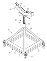
도 1은 본 고안에 의한 롤러를 이용하여 파이프를 회전시키기 위한 파이프 회전지지장치의 구성을 보인 사시도.
도 2는 본 고안에 의한 롤러를 이용하여 파이프를 회전시키기 위한 파이프 회전지지장치의 구성을 보인 측면도. 1 is a perspective view showing the configuration of a pipe rotation support device for rotating a pipe using a roller according to the present invention.
Figure 2 is a side view showing the configuration of the pipe rotation support device for rotating the pipe using a roller according to the present invention.
이하 본 고안의 실시 예를 첨부된 도면을 참조해서 상세히 설명하면 다음과 같다.Hereinafter, an embodiment of the present invention will be described in detail with reference to the accompanying drawings.
도 1 및 도 2는 본 고안에 의한 롤러를 이용하여 파이프를 회전시키기 위한 파이프 회전지지장치 구성을 보인 사시도 및 측면도이다. 이에 도시된 바와 같이,1 and 2 are a perspective view and a side view showing the configuration of the pipe rotation support device for rotating the pipe using a roller according to the present invention. As shown therein,
회전지지장치의 베이스 프레임을 이루며, 서로 대응된 두 라인이 LM레일(11)로 이루어지고 LM레일(11)에 좌우 이동 가능한 LM블록(12)이 설치된 LM장치(10)와;An
상기 LM블록(12)에 고정설치되어 좌우 이동이 가능하며, 상부로 지지대(22)가 설치된 지지부(20)와;A
상기 지지부(20)에 결합 설치되어 상하 이동에 대한 완충 작용을 하는 완충장치(30)와;A
상기 완충장치(30)에 결합되어 상하로 완충 지지되는 지지샤프트(40)와;A
상기 지지샤프트(40)의 상단에 중앙부가 일체형으로 고정설치되고, 롤러(60)가 삽입되는 롤러홈(51)의 양측면에 복수의 롤러축 결합홈(52)이 형성된 파이프 받침대(50)와;A
상기 파이프 받침대(50)의 롤러축 결합홈(52)에 롤러 축이 회전가능하게 결합되고, 상면에 올려지는 파이프와 접하여 파이프를 회전시킬 수 있도록 결합되는 한 쌍의 롤러(60)를 포함하여 구성된다.The roller shaft is rotatably coupled to the roller
상기 LM장치(10)에는 절첩 가능하게 설치되는 복수의 볼 캐스트 장치(70)가 더 설치되어 구성된다.The
상기 LM장치(10)는, 두 개의 LM레일(11)이 두 개의 베이스 프레임에 의해 연결되어 사각형 베이스 프레임으로 구성되고, 앞뒤에 설치되는 두 개의 LM레일(11)의 LM블록(12)에는 지지부(20)의 지지프레임(21)이 고정되며, 지지프레임(21)은 상기 사각형 베이스 프레임과 대응되게 사각형 지지 프레임으로 구성된다. The
상기 지지부(20)는, 하부의 지지프레임(21)에 상부로 복수의 지지대(22)가 설치되고, 복수의 지지대(22)의 상단에 완충장치(30)가 설치된다.The
상기 완충장치(30)는, 상기 복수의 지지대(22)에 의해 고정지지되고, 상기 지지샤프트(40)가 상하 슬라이드 가능하게 삽입되는 원통부(31)와, 상기 원통부(31)의 상단부에 압축 스프링의 하단부가 지지되게 상기 지지샤프트(40)의 외주면에 삽입 결합되는 압축 스프링(32)과, 상기 지지 샤프트(40)의 상단에서 중단까지 외주면에 스크류(41)가 형성되고, 상기 스크류(41)에 나사 결합되어 양측으로 손잡이가 돌출 형성되고 상기 압축 스프링(32)의 상단부가 걸리는 압축 스프링 장력조절바(33)를 포함하여 구성된다.The
여기서, 실시 예로서 압축 스프링(32)을 이용한 완충장치(30)의 구성을 예시하였으나, 이에 한정되지 아니하고, 유압 또는 공압을 이용하는 완충장치를 구성할 수 있다. 예컨대, 상기 원통부(31)를 유압 실린더로 구성하고, 유압실린더의 작동로드에 상기 지지샤프트(40)를 고정 결합시켜 유압에 의해 완충기능을 달성하도록 할 수 있으며, 동일하게 공압 실린더를 이용할 수도 있고, 높이 조절을 위하여 지지샤프트와 유압실린더의 작동로드 사이에 스크류 잭과 같은 형태의 높이조절수단을 더 포함하여 구성할 수도 있다.Here, although the configuration of the shock absorber 30 using the
상기 파이프 받침대(50)는, 중앙부가 낮고 양측부가 높은 라운드 형태의 프레임으로 구성하고, 내측부에 롤러가 삽입되는 롤러홈(51)이 형성되고, 롤러홈(51)의 양측부에 롤러축을 회전가능하게 삽입결합하기 위한 롤러축 결합홈(52)이 형성된다. 롤러축 결합홈(52)은 중심부의 중앙을 기준으로 양측으로 동일한 간격으로 띄어서 복수의 롤러축 결합홈(52)이 형성된다.The
롤러(60)는 롤러축을 상기 롤러축 결합홈(52)에 결합시켜 롤러홈(51)에 삽입장착하되, 좌우 양측으로 한 쌍의 롤러(60)를 결합 설치한다.The
롤러(60)의 상부에 작업하기 위한 파이프를 올려놓으면, 압축 스프링(32)의 완충력으로 탄력적으로 지지되며, 파이프를 회전시키면, 롤러(60)가 회전되면서 작은 힘으로 파이프를 회전시킬 수 있다.When the pipe for working on the upper portion of the
한편, 파이프가 대구경 형상관이고, 가지관이 돌출 형성된 경우, 가지관의 단부에도 본 고안의 파이프 회전지지장치를 설치하여 지지하도록 하고, 압축 스프링 압력조절바(33)를 회전시켜 높이를 조절함으로써 파이프의 회전시 안정되게 지지할 수 있다. 물론 가지관이 상향되는 방향으로 파이프를 회전시키는 경우는 회전지지가 어려우나, 가지관이 파이프의 일측 또는 타측방향으로 수평형태로 위치될때에는 본 고안의 회전지지정치를 사용하여 지지할 수 있고, 지지하기 위한 높이도 조절과 함께 완충기능을 수행함으로써, 파이프를 회전시키면서 용접이나 절단 작업을 할 때 가지관으로 인한 불균형이 발생되어 작업 위치로 알맞게 지지하지 못하던 종래의 문제점을 해결할 수 있게 된다.On the other hand, when the pipe is a large-diameter tube, the branch pipe is formed to protrude, the pipe rotation support device of the present invention is also installed and supported at the end of the branch pipe, by adjusting the height by rotating the compression spring
또한, 본 고안은 지지부(20)가 하부의 LM장치(10)에 고정설치되어 좌우방향으로 이동이 가능하므로, 지지장치 전체를 이동시키지 않고서도 LM장치(10)에 의해 좌우 슬라이딩시켜 무게중심의 지지위치에서 지지할 수 있게 된다.In addition, the present invention is because the
또한, 본 고안은 LM장치(10)의 4모서리부분에 절첩식 볼 캐스트장치(70)를 설치하여, 이동시 볼캐스트장치(70)를 이용하여 밀어서 쉽게 이동시킬 수 있고, 작업시에는 파이프의 중량을 견딜 수 있도록 볼캐스트장치(70)는 상향으로 절첩시켜 바닥면과 이격되게 하고, LM장치(10)가 바닥면에 지지되도록 함으로써 이동 및 작업시의 고정이 용이 해진다.In addition, the present invention is installed on the four corners of the
10 : LM장치 11 : LM레일
12 : LM블록 20 : 지지부
21 : 지지프레임 22 : 지지대
30 : 완충장치 31 : 원통부
32 : 압축 스프링 33 : 압축 스프링 장력 조절바
40 : 지지샤프트 41 : 스크류부
50 : 파이프 받침대 51 : 롤러홈
52 : 롤러축 결합홈 60 : 롤러
70 : 볼캐스트 장치 10: LM device 11: LM rail
12: LM block 20: support
21: support frame 22: support
30: shock absorber 31: cylindrical portion
32: compression spring 33: compression spring tension adjustment bar
40: support shaft 41: screw portion
50: pipe support 51: roller groove
52: roller shaft coupling groove 60: roller
70: ballcast device
Claims (4)
회전지지장치의 베이스 프레임을 이루며, 서로 대응된 두 라인이 LM레일(11)로 이루어지고 LM레일(11)에 좌우 이동 가능한 LM블록(12)이 설치된 LM장치(10)와;
상기 LM블록(12)에 고정설치되어 좌우 이동이 가능하며, 상부로 지지대(22)가 설치된 지지부(20)와;
상기 지지부(20)에 결합 설치되어 상하 이동에 대한 완충 작용을 하는 완충장치(30)와;
상기 완충장치(30)에 결합되어 상하로 완충 지지되는 지지샤프트(40)와;
상기 지지샤프트(40)의 상단에 중앙부가 일체형으로 고정설치되고, 롤러(60)가 삽입되는 롤러홈(51)의 양측면에 복수의 롤러축 결합홈(52)이 형성된 파이프 받침대(50)와;
상기 파이프 받침대(50)의 롤러축 결합홈(52)에 롤러축이 회전가능하게 결합되고, 상면에 올려지는 파이프와 접하여 파이프를 회전시킬 수 있도록 결합되는 한 쌍의 롤러(60)를 포함하여 구성된 것을 특징으로 하는 파이프 회전지지장치.
In the pipe rotation support device for supporting the pipe to rotate during welding and cutting of the pipe,
An LM device 10 constituting the base frame of the rotation support device, the two lines corresponding to each other being formed of the LM rails 11 and having an LM block 12 movable on the LM rails 11;
A support part 20 fixed to the LM block 12 to move left and right and having a support 22 installed thereon;
A shock absorber 30 coupled to the support part 20 to provide a shock absorbing function for vertical movement;
A support shaft 40 coupled to the shock absorber 30 and fully buffered up and down;
A pipe supporter 50 having a central portion integrally fixed to an upper end of the support shaft 40 and having a plurality of roller shaft coupling grooves 52 formed on both sides of the roller groove 51 into which the rollers 60 are inserted;
The roller shaft is rotatably coupled to the roller shaft coupling groove 52 of the pipe supporter 50, and includes a pair of rollers 60 coupled to contact the pipe mounted on the upper surface to rotate the pipe. Pipe rotation support device, characterized in that.
The pipe rotation support device according to claim 1, wherein the LM device (10) is further provided with a plurality of ball cast devices (70) which are foldable.
상기 지지대(22)에 의해 고정지지되고, 상기 지지샤프트(40)가 상하 슬라이드 가능하게 삽입되는 원통부(31)와,
상기 원통부(31)의 상단부에 압축 스프링의 하단부가 지지되게 상기 지지샤프트(40)의 외주면에 삽입 결합되는 압축 스프링(32)과,
상기 지지 샤프트(40)의 상단에서 중단까지 외주면에 스크류(41)가 형성되고, 상기 스크류(41)에 나사 결합되어 양측으로 손잡이가 돌출 형성되고 상기 압축 스프링(32)의 상단부가 걸리는 압축 스프링 장력조절바(33)를 포함하여 구성된 것을 특징으로 하는 파이프 회전지지장치.
The method of claim 1, wherein the shock absorber 30,
A cylindrical portion 31 fixedly supported by the support 22 and into which the support shaft 40 is slidably inserted;
A compression spring 32 inserted into and coupled to an outer circumferential surface of the support shaft 40 such that the lower end of the compression spring is supported at the upper end of the cylindrical portion 31;
A screw 41 is formed on an outer circumferential surface of the support shaft 40 from the top to the middle of the support shaft 40. Pipe rotation support device characterized in that it comprises a control bar (33).
상기 지지대(22)에 의해 지지되는 유압 실린더를 설치하고, 유압실린더의 작동로드에 상기 지지샤프트(40)를 고정 결합시켜 유압에 의해 완충 기능이 이루어지도록 구성하되, 지지샤프트와 유압실린더의 작동로드 사이에 길이 조절이 가능한 높이조절수단을 더 포함하여 구성된 것을 특징으로 하는 파이프 회전지지장치.The method of claim 1, wherein the buffer unit 30,
The hydraulic cylinder supported by the support 22 is installed, and the support shaft 40 is fixedly coupled to the operating rod of the hydraulic cylinder to be configured to perform a shock absorbing function by hydraulic pressure, but the operating shaft of the support shaft and the hydraulic cylinder is configured. Pipe rotation support device characterized in that it further comprises a height adjustment means capable of adjusting the length between.
Priority Applications (1)
| Application Number | Priority Date | Filing Date | Title |
|---|---|---|---|
| KR2020110005907U KR200479122Y1 (en) | 2011-06-29 | 2011-06-29 | Apparatus for supporting rotation of pipe |
Applications Claiming Priority (1)
| Application Number | Priority Date | Filing Date | Title |
|---|---|---|---|
| KR2020110005907U KR200479122Y1 (en) | 2011-06-29 | 2011-06-29 | Apparatus for supporting rotation of pipe |
Publications (2)
| Publication Number | Publication Date |
|---|---|
| KR20130000169U true KR20130000169U (en) | 2013-01-08 |
| KR200479122Y1 KR200479122Y1 (en) | 2015-12-22 |
Family
ID=51356134
Family Applications (1)
| Application Number | Title | Priority Date | Filing Date |
|---|---|---|---|
| KR2020110005907U KR200479122Y1 (en) | 2011-06-29 | 2011-06-29 | Apparatus for supporting rotation of pipe |
Country Status (1)
| Country | Link |
|---|---|
| KR (1) | KR200479122Y1 (en) |
Cited By (6)
| Publication number | Priority date | Publication date | Assignee | Title |
|---|---|---|---|---|
| KR101530908B1 (en) * | 2013-12-14 | 2015-06-23 | 이진성 | Welding apparatus for branched tube |
| CN105945840A (en) * | 2016-06-28 | 2016-09-21 | 苏州市宏业灯具设备有限公司 | Clamping device for galvanizing of street lamp post |
| CN106392703A (en) * | 2016-11-11 | 2017-02-15 | 四川多联实业有限公司 | Adjustable clamping fixing system for polyvinyl chloride (PVC) pipe |
| KR101843308B1 (en) * | 2017-03-22 | 2018-03-28 | 주식회사 신화금속 | A spray coating method of zirconium tube |
| KR102335432B1 (en) * | 2021-06-07 | 2021-12-03 | 김동엽 | Metal cutter |
| CN114193044A (en) * | 2022-01-14 | 2022-03-18 | 锋宏泰尼克精密件技术(昆山)有限公司 | Receiving piece of fixed disk of clamp welding device with buffering function |
Families Citing this family (1)
| Publication number | Priority date | Publication date | Assignee | Title |
|---|---|---|---|---|
| KR101792172B1 (en) * | 2016-02-17 | 2017-11-20 | 삼성중공업 주식회사 | Device for supporting connecting bar |
Citations (4)
| Publication number | Priority date | Publication date | Assignee | Title |
|---|---|---|---|---|
| KR19980013037U (en) * | 1996-08-27 | 1998-06-05 | 박언규 | Belt tensioning device for twisting machine |
| KR200317628Y1 (en) * | 2003-03-26 | 2003-06-25 | 이종하 | Jig for welding pipes |
| JP2005081408A (en) * | 2003-09-10 | 2005-03-31 | Halla Climate Control Corp | Method of producing piston for swash plate type compressor with variable capacity |
| KR20110065198A (en) * | 2009-12-09 | 2011-06-15 | 주식회사 에이치케이알 | Pipe position control device and cutting machine therewith |
-
2011
- 2011-06-29 KR KR2020110005907U patent/KR200479122Y1/en not_active IP Right Cessation
Patent Citations (4)
| Publication number | Priority date | Publication date | Assignee | Title |
|---|---|---|---|---|
| KR19980013037U (en) * | 1996-08-27 | 1998-06-05 | 박언규 | Belt tensioning device for twisting machine |
| KR200317628Y1 (en) * | 2003-03-26 | 2003-06-25 | 이종하 | Jig for welding pipes |
| JP2005081408A (en) * | 2003-09-10 | 2005-03-31 | Halla Climate Control Corp | Method of producing piston for swash plate type compressor with variable capacity |
| KR20110065198A (en) * | 2009-12-09 | 2011-06-15 | 주식회사 에이치케이알 | Pipe position control device and cutting machine therewith |
Cited By (6)
| Publication number | Priority date | Publication date | Assignee | Title |
|---|---|---|---|---|
| KR101530908B1 (en) * | 2013-12-14 | 2015-06-23 | 이진성 | Welding apparatus for branched tube |
| CN105945840A (en) * | 2016-06-28 | 2016-09-21 | 苏州市宏业灯具设备有限公司 | Clamping device for galvanizing of street lamp post |
| CN106392703A (en) * | 2016-11-11 | 2017-02-15 | 四川多联实业有限公司 | Adjustable clamping fixing system for polyvinyl chloride (PVC) pipe |
| KR101843308B1 (en) * | 2017-03-22 | 2018-03-28 | 주식회사 신화금속 | A spray coating method of zirconium tube |
| KR102335432B1 (en) * | 2021-06-07 | 2021-12-03 | 김동엽 | Metal cutter |
| CN114193044A (en) * | 2022-01-14 | 2022-03-18 | 锋宏泰尼克精密件技术(昆山)有限公司 | Receiving piece of fixed disk of clamp welding device with buffering function |
Also Published As
| Publication number | Publication date |
|---|---|
| KR200479122Y1 (en) | 2015-12-22 |
Similar Documents
| Publication | Publication Date | Title |
|---|---|---|
| KR20130000169U (en) | Apparatus for supporting rotation of pipe | |
| JP2014522734A5 (en) | ||
| CN212043360U (en) | Pipeline strutting arrangement is used in pipeline welding | |
| CN109868988A (en) | A kind of scaffold final door frame and its production equipment | |
| CN103507051A (en) | Rotation opening mechanism of rotary examining table | |
| KR20110057551A (en) | Load mounting apparatus | |
| KR20130020387A (en) | Surface plate having jig for supporting carriage rail | |
| CN204164504U (en) | Pump concrete pump line vibration damping support device | |
| CN104149989A (en) | Adjustable rolling mechanism for rocket bodies of various diameter specifications | |
| CN103394932B (en) | H type, box-type member and cross column end mill stationary fixture | |
| CN212107523U (en) | Buffer device of anti-seismic support | |
| KR20110010875U (en) | Rotation apparatus for pipe welding | |
| CN216462649U (en) | Welding device of filter element central tube rolling machine | |
| KR101144922B1 (en) | ladder up and down Device for vessel | |
| CN210906828U (en) | Vibrating device for papermaking equipment | |
| KR101733587B1 (en) | An auxiliary device for packanging scooters | |
| CN111390572B (en) | Omnidirectional machining device convenient for teaching | |
| KR20180003229U (en) | Work platform moving device for tunnel construction | |
| KR200215532Y1 (en) | The cutting machine for large steel pipe in piping work | |
| CN109465801B (en) | Clamping table for machining automobile bearing | |
| CN215445596U (en) | Damping mechanism for pipe bending machine | |
| CN220451490U (en) | Reinforcing apparatus of high-rise floor beam | |
| CN211679331U (en) | Steel wire vibration absorption device and straight wire drawing machine | |
| CN216280114U (en) | Anti-vibration stabilizing structure of superclean bench | |
| CN215674303U (en) | Damping seat of rolling mill |
Legal Events
| Date | Code | Title | Description |
|---|---|---|---|
| A201 | Request for examination | ||
| E902 | Notification of reason for refusal | ||
| E701 | Decision to grant or registration of patent right | ||
| LAPS | Lapse due to unpaid annual fee |