KR20120121237A - Bracket for shock absorber - Google Patents
Bracket for shock absorber Download PDFInfo
- Publication number
- KR20120121237A KR20120121237A KR1020110039095A KR20110039095A KR20120121237A KR 20120121237 A KR20120121237 A KR 20120121237A KR 1020110039095 A KR1020110039095 A KR 1020110039095A KR 20110039095 A KR20110039095 A KR 20110039095A KR 20120121237 A KR20120121237 A KR 20120121237A
- Authority
- KR
- South Korea
- Prior art keywords
- bracket
- shock absorber
- knuckle
- integrated
- stabilizer link
- Prior art date
- Legal status (The legal status is an assumption and is not a legal conclusion. Google has not performed a legal analysis and makes no representation as to the accuracy of the status listed.)
- Ceased
Links
- 230000035939 shock Effects 0.000 title claims abstract description 74
- 239000006096 absorbing agent Substances 0.000 title claims abstract description 70
- 239000003381 stabilizer Substances 0.000 claims abstract description 41
- 238000000034 method Methods 0.000 claims description 13
- 238000003780 insertion Methods 0.000 claims description 5
- 230000037431 insertion Effects 0.000 claims description 5
- 238000003466 welding Methods 0.000 claims description 3
- 239000000725 suspension Substances 0.000 description 9
- 230000008569 process Effects 0.000 description 8
- 230000008901 benefit Effects 0.000 description 3
- 230000008878 coupling Effects 0.000 description 3
- 238000010168 coupling process Methods 0.000 description 3
- 238000005859 coupling reaction Methods 0.000 description 3
- 238000003825 pressing Methods 0.000 description 2
- 238000012545 processing Methods 0.000 description 2
- 206010034719 Personality change Diseases 0.000 description 1
- 230000009471 action Effects 0.000 description 1
- 230000002238 attenuated effect Effects 0.000 description 1
- 230000005540 biological transmission Effects 0.000 description 1
- 238000005520 cutting process Methods 0.000 description 1
- 238000010586 diagram Methods 0.000 description 1
- 230000000694 effects Effects 0.000 description 1
- 239000012212 insulator Substances 0.000 description 1
- 230000001788 irregular Effects 0.000 description 1
- 239000000463 material Substances 0.000 description 1
- 238000012986 modification Methods 0.000 description 1
- 230000004048 modification Effects 0.000 description 1
- 230000002093 peripheral effect Effects 0.000 description 1
- 230000003252 repetitive effect Effects 0.000 description 1
- 238000005096 rolling process Methods 0.000 description 1
Images

Classifications
-
- B—PERFORMING OPERATIONS; TRANSPORTING
- B60—VEHICLES IN GENERAL
- B60G—VEHICLE SUSPENSION ARRANGEMENTS
- B60G13/00—Resilient suspensions characterised by arrangement, location or type of vibration dampers
- B60G13/02—Resilient suspensions characterised by arrangement, location or type of vibration dampers having dampers dissipating energy, e.g. frictionally
- B60G13/06—Resilient suspensions characterised by arrangement, location or type of vibration dampers having dampers dissipating energy, e.g. frictionally of fluid type
-
- B—PERFORMING OPERATIONS; TRANSPORTING
- B60—VEHICLES IN GENERAL
- B60G—VEHICLE SUSPENSION ARRANGEMENTS
- B60G11/00—Resilient suspensions characterised by arrangement, location or kind of springs
- B60G11/14—Resilient suspensions characterised by arrangement, location or kind of springs having helical, spiral or coil springs only
-
- B—PERFORMING OPERATIONS; TRANSPORTING
- B60—VEHICLES IN GENERAL
- B60G—VEHICLE SUSPENSION ARRANGEMENTS
- B60G13/00—Resilient suspensions characterised by arrangement, location or type of vibration dampers
-
- B—PERFORMING OPERATIONS; TRANSPORTING
- B60—VEHICLES IN GENERAL
- B60G—VEHICLE SUSPENSION ARRANGEMENTS
- B60G15/00—Resilient suspensions characterised by arrangement, location or type of combined spring and vibration damper, e.g. telescopic type
- B60G15/02—Resilient suspensions characterised by arrangement, location or type of combined spring and vibration damper, e.g. telescopic type having mechanical spring
-
- B—PERFORMING OPERATIONS; TRANSPORTING
- B60—VEHICLES IN GENERAL
- B60G—VEHICLE SUSPENSION ARRANGEMENTS
- B60G3/00—Resilient suspensions for a single wheel
- B60G3/18—Resilient suspensions for a single wheel with two or more pivoted arms, e.g. parallelogram
-
- F—MECHANICAL ENGINEERING; LIGHTING; HEATING; WEAPONS; BLASTING
- F16—ENGINEERING ELEMENTS AND UNITS; GENERAL MEASURES FOR PRODUCING AND MAINTAINING EFFECTIVE FUNCTIONING OF MACHINES OR INSTALLATIONS; THERMAL INSULATION IN GENERAL
- F16F—SPRINGS; SHOCK-ABSORBERS; MEANS FOR DAMPING VIBRATION
- F16F9/00—Springs, vibration-dampers, shock-absorbers, or similarly-constructed movement-dampers using a fluid or the equivalent as damping medium
- F16F9/32—Details
- F16F9/34—Special valve constructions; Shape or construction of throttling passages
Landscapes
- Engineering & Computer Science (AREA)
- Mechanical Engineering (AREA)
- General Engineering & Computer Science (AREA)
- Vehicle Body Suspensions (AREA)
Abstract
Description
본 발명은 쇼크 업소버용 브래킷에 관한 것으로서, 특히 쇼크 업소버 조립 시 복수의 브래킷 적용으로 인해 조립 공정이 복잡해지고 원가와 중량이 증가하게 되는 현상을 방지하기 위한 쇼크 업소버용 브래킷에 관한 것이다.
The present invention relates to a shock absorber bracket, and more particularly, to a shock absorber bracket for preventing a phenomenon in which the assembly process becomes complicated and the cost and weight increase due to the application of a plurality of brackets when the shock absorber is assembled.
일반적으로 차량의 현가장치는 차축과 차체 사이를 연결시켜 주행 중에 차축이 노면으로부터 받는 진동이나 충격 등을 적절히 감쇠시킴과 더불어, 차체의 손상과 탑승자의 승차감을 향상시킬 수 있게 하는 것이다.In general, the suspension of the vehicle is connected between the axle and the body to properly attenuate the vibration or shock received from the road surface while driving, and to improve the damage of the vehicle body and the ride comfort of the occupant.
즉, 현가장치는 차량의 상하 방향으로 유연성을 제공하여 노면의 거침으로부터 차체가 영향을 받지 않게 하면서 불규칙한 노면을 주행할 수 있게 하면서, 노면에 대하여 적절한 조향 및 캠버 위치에 휠을 유지시킴과 더불어 차륜에 의해서 발생하는 수평 및 횡력 그리고 제동 및 구동력에 대응함과 아울러 차체의 롤링을 억제하는 작용을 하게 된다.In other words, the suspension system provides flexibility in the vertical direction of the vehicle so that the vehicle can travel on irregular roads without being affected by the roughness of the road, while maintaining the wheels at the proper steering and camber positions with respect to the road surface. Corresponding to the horizontal and lateral forces and the braking and driving force generated by the action as well as to suppress the rolling of the vehicle body.
이러한 현가장치 중 쇼크 업소버(Shock Absorber)는 일단이 차체 쪽으로 체결되고 타단은 차륜에 장착된 너클 부위로 체결된다.Of these suspensions, the shock absorber (Shock Absorber) is fastened to the vehicle body one end and the other end is fastened to the knuckle portion mounted to the wheel.
이때, 쇼크 업소버의 외주면에는 너클과 체결되기 위한 마운팅 브래킷이 구비되며, 또한 스태빌라이저 링크와 체결시키기 위한 추가 브래킷이 구비되는 것이 일반적이다.
In this case, a mounting bracket for fastening with the knuckle is provided on the outer circumferential surface of the shock absorber, and an additional bracket for fastening with the stabilizer link is generally provided.
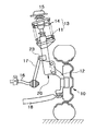
도 1은 종래의 차량용 현가장치를 도시하는 단면도이며, 도 2는 종래의 쇼크 업소버용 브래킷을 도시하는 도면이다.1 is a cross-sectional view showing a conventional vehicle suspension, and FIG. 2 is a view showing a conventional shock absorber bracket.
종래의 차량용 현가장치는 도 1에 도시된 바와 같이, 차륜(10)을 회전 가능하게 지지하는 너클(12)이 구비되며, 상기 너클(12)의 하단이 로워 컨트롤 아암(15)과 연결되고, 상단이 코일 스프링(14)과 쇼크 업소버(11)가 일체로 형성되는 스트러트 어셈블리(13)와 연결된다. As shown in FIG. 1, a conventional vehicle suspension device includes a
그리고 스트러트 어셈블리(13)의 상단부는 차체(미도시)에 인슐레이터(15)를 지지하게 되며, 쇼크 업소버(11)의 중간부 내측에는 스태빌라이저(16)가 연결된다.The upper end of the
이에 따라 노면으로부터 입력되는 진동 및 충격이 스트러트 어셈블리(13)에 의해 감쇠되어 차체에 전달되는 진동과 충격을 최소화하게 되는 것이다.Accordingly, the vibration and shock input from the road surface are attenuated by the
상기와 같은 스트러트 현가장치는 구조가 간단하여 경량화 및 공간 확보와 원가가 저렴하고, 엔진룸의 공간 확보가 유리하며, 장착 위치에 따른 차륜(10)의 자세 변화가 작다는 장점을 가지고 있으나, 차량 성능 측면에서 한계를 내포하고 있다. The strut suspension as described above has the advantage that the structure is simple, light weight and secure space and low cost, the space of the engine room is advantageous, the attitude change of the
한편, 종래의 차량용 현가장치의 쇼크 업소버용 브래킷은 도 1 및 도 2에 도시된 바와 같이, 쇼크 업소버(11) 외주면에 너클(12)과 체결되는 너클 브래킷(20)과, 스태빌라이저(16)와 연결되는 스태빌라이저 링크(17)와 체결되는 스태빌라이저 링크 브래킷(23)이 장착된다.Meanwhile, as shown in FIGS. 1 and 2, the shock absorber bracket of the conventional vehicle suspension device includes a
이때, 너클 브래킷(20)은 외측 너클 브래킷(21)과 내측 너클 브래킷(22)으로 이루어져 너클(12)과 체결되도록 한다.At this time, the
그러나, 종래의 쇼크 업소버용 브래킷에서 외측 너클 브래킷 및 내측 너클 브래킷을 포함하는 너클 브래킷과, 스태빌라이저 링크 브래킷을 쇼크 업소버에 적용하게 되면 각각의 브래킷을 쇼크 업소버에 결합시켜야 하기 때문에 조립 공정이 복잡해지고, 또한 각각의 브래킷 성형 시 재질 및 형상이 상이하므로 개별적인 가공 작업을 거치야 하기 때문에 원가와 중량이 증가하게 되는 문제점이 있었다.
However, in the conventional shock absorber bracket, when the knuckle bracket including the outer knuckle bracket and the inner knuckle bracket and the stabilizer link bracket are applied to the shock absorber, the assembly process is complicated because each bracket must be coupled to the shock absorber. In addition, since the material and shape are different when forming each bracket, there is a problem in that the cost and weight increase because the individual processing must be performed.
본 발명은 상기의 문제점을 해소하기 위한 쇼크 업소버용 브래킷에 관한 것으로서, 특히 쇼크 업소버 조립 시 복수의 브래킷 적용으로 인해 조립 공정이 복잡해지고 원가와 중량이 증가하게 되는 현상을 방지하기 위한 것을 목적으로 한다.
The present invention relates to a shock absorber bracket for solving the above problems, and particularly to prevent the phenomenon that the assembly process is complicated and the cost and weight increase due to the application of a plurality of brackets when the shock absorber assembly. .
이러한 본 발명은 차륜을 회전 가능하게 지지하는 너클과, 차체에 장착된 스태빌라이저와 연결되는 스태빌라이저 링크와, 일측은 차체와 연결되고 타측은 상기 너클과 연결되는 쇼크 업소버가 구비되되; 상기 쇼크 업소버 외주면에 통합브래킷이 구비됨으로써 달성된다.
The present invention is provided with a knuckle for rotatably supporting the wheel, a stabilizer link connected to a stabilizer mounted on the vehicle body, and a shock absorber connected to one side of the vehicle body and the other side to the knuckle; This is achieved by providing an integrated bracket on the outer surface of the shock absorber.
이상과 같은 본 발명은 단일의 마운팅 브래킷을 적용하면서도 복수의 브래킷으로 체결할 때와 같은 내구성과 충돌에 대한 강성을 확보하는 동시에, 조립 시 체결 부위 및 볼팅 수량을 줄여 원가와 중량은 물론 조립 공정도 줄임으로써 상품성을 향상시키는데 효과가 있는 발명인 것이다.
The present invention as described above, while applying a single mounting bracket while securing the durability and rigidity as when tightening with a plurality of brackets, while reducing the fastening site and the number of bolts when assembling cost and weight as well as the assembly process It is an invention which is effective in improving the merchandise by reducing it.
도 1은 종래의 차량용 현가장치를 도시하는 단면도,
도 2는 종래의 쇼크 업소버용 브래킷을 도시하는 도면,
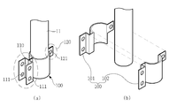
도 3의 (a)는 본 발명의 쇼크 업소버용 브래킷에서 쇼크 업소버에 장착된 통합브래킷을 도시하는 도면,
도 3의 (b)는 본 발명의 쇼크 업소버용 브래킷에서 쇼크 업소버에 장착되는 제1통합브래킷과 제2통합브래킷을 도시하는 도면,
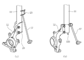
도 4의 (a)는 종래의 쇼크 업소버용 브래킷의 실시예를 도시하는 도면이며, 도 4의 (b)는 본 발명의 쇼크 업소버용 브래킷의 실시예를 도시하는 도면.1 is a cross-sectional view showing a conventional vehicle suspension device;
2 is a view showing a conventional shock absorber bracket,
Figure 3 (a) is a view showing the integrated bracket mounted to the shock absorber in the shock absorber bracket of the present invention,
Figure 3 (b) is a view showing a first integrated bracket and a second integrated bracket mounted to the shock absorber in the shock absorber bracket of the present invention,
Figure 4 (a) is a view showing an embodiment of a conventional shock absorber bracket, Figure 4 (b) is a view showing an embodiment of a shock absorber bracket of the present invention.
도 3 및 도 4는 본 발명의 쇼크 업소버용 브래킷에 관한 것으로, 도 3은 본 발명의 쇼크 업소버용 브래킷에서 쇼크 업소버에 장착된 통합브래킷을 도시하는 도면이며, 도 4는 종래의 쇼크 업소버용 브래킷의 실시예와 본 발명의 쇼크 업소버용 브래킷의 실시예를 비교하는 도면이다.
3 and 4 are related to the shock absorber bracket of the present invention, Figure 3 is a view showing the integrated bracket mounted to the shock absorber in the shock absorber bracket of the present invention, Figure 4 is a conventional shock absorber bracket Is a diagram comparing the embodiment of the shock absorber bracket of the present invention.
본 발명의 실시예를 첨부 도면을 참조하여 상세히 설명하면 다음과 같다.DETAILED DESCRIPTION OF THE PREFERRED EMBODIMENTS Hereinafter, embodiments of the present invention will be described in detail with reference to the accompanying drawings.
본 발명의 쇼크 업소버용 브래킷은 도 3 및 도 4에 도시된 바와 같이, 제1통합브래킷(101)과 제2통합브래킷(102)으로 이루어진 통합브래킷(100)이 쇼크 업소버(11) 외주면에 용접을 통해 장착되도록 하여 조립 시 체결 부위 및 볼팅 수량을 줄여 원가와 중량은 물론 조립 공정도 줄임으로써 상품성을 향상시키게 되는 것을 그 기술상의 기본 특징으로 한다.
In the shock absorber bracket of the present invention, as shown in FIGS. 3 and 4, the integrated
이하 본 발명의 쇼크 업소버용 브래킷에 대한 각 구성요소를 첨부한 도면을 참조하여 하나씩 살펴보면 다음과 같다.Hereinafter, each component of the shock absorber bracket of the present invention will be described with reference to the accompanying drawings, one by one.
우선 본 발명은 도 4의 (b)에 도시된 바와 같이, 차륜을 회전 가능하게 지지하는 너클(12)과, 차체에 장착된 스태빌라이저(16)와 연결되는 스태빌라이저 링크(17)와, 일측은 차체와 연결되고 타측은 상기 너클(12)과 연결되는 쇼크 업소버(shock absorber, 11)가 구비되는 것을 기본으로 한다.First, as shown in FIG. 4B, the present invention is a
여기서, 쇼크 업소버(11)는 자동차의 서스펜션을 구성하는 주요 요소 가운데 하나로서, 차체와 바퀴 사이에 장착되어 차량의 흔들림에 대한 브레이크(저항) 역할을 하는 것으로, 스프링의 수축을 조절해, 노면 차이로 인해 충격을 받은 스프링이 상하방향으로 반복해서 되튐(recoil)운동을 하게 되는 것을 막아 줌으로써 스프링이 원상태로 천천히 돌아갈 수 있도록 하는 것이다.Here, the shock absorber 11 is one of the main components constituting the suspension of the vehicle, and is mounted between the vehicle body and the wheels to act as a brake (resistance) against the shaking of the vehicle. This prevents the spring shocked by the repetitive movement in the up and down direction so that the spring can be slowly returned to its original state.
한편, 차륜을 회전 가능하게 지지하는 너클(12)은 그 일측이 차륜 측에 연결되며 타측은 쇼크 업소버(11)와 연결되도록 하여 차륜으로 흡수된 충격을 쇼크 업소버(11)를 통해 감쇠시켜 차체에 진동 전달을 저감시키도록 한다.On the other hand, the
또한, 차체에 장착되는 스태빌라이저(16)는 차량의 상하 진동을 막아주는 쇼크 업소버(11)와 달리 차체의 좌우 흔들림을 방지하는 역할을 하는 것으로, 상기 스태빌라이저(16)의 일측은 차체와 연결되며 타측은 스태빌라이저 링크(17)와 연결되어 쇼크 업소버(11)와 연결되도록 함으로써, 차체의 좌우 흔들림에 대한 충격을 쇼크 업소버(11)를 통해 저감시키도록 한다.In addition, unlike the shock absorber 11 which prevents the up and down vibration of the vehicle, the
이때, 본 발명의 쇼크 업소버용 브래킷은 도 3에 도시된 바와 같이, 원통 형상으로 이루어진 쇼크 업소버(11)의 외주면에 통합브래킷(100)이 구비되도록 하여 상기 통합브래킷(100)의 일측은 너클(12)과 체결되며, 타측은 스태빌라이저 링크(17)와 체결되도록 한다.At this time, the shock absorber bracket of the present invention, as shown in Figure 3, so that the integrated
여기서, 통합브래킷(100)은 제1통합브래킷(101)과 제2통합브래킷(102)으로 분할 형성되도록 하여, 조립 전에는 상기 제1통합브래킷(101)과 제2통합브래킷(102)이 별도로 구비되도록 하며 조립 공정 시 쇼크 업소버(11)에 상기 제1통합브래킷(101)과 제2통합브래킷(102)을 조립시켜 일체화 시키도록 한다.Here, the integrated
한편, 쇼크 업소버(11) 외주면에 제1통합브래킷(101)과 제2통합브래킷(102) 장착 시 용접을 통해 결합되도록 하여 상기 쇼크 업소버(11)와 통합브래킷(100)의 체결력을 향상시키도록 한다.Meanwhile, when the first integrated
이때, 제1통합브래킷(101)과 제2통합브래킷(102)의 일측은 절곡되어 너클 삽입부(110)가 형성되어 너클(12)이 삽입되도록 하며, 타측은 스태빌라이저 링크 체결부(120)가 형성되어 스태빌라이저 링크(17)와 체결될 수 있게 하는 것이 바람직하다.At this time, one side of the first integrated
또한, 제1통합브래킷(101)과 제2통합브래킷(102)을 포함하는 통합브래킷(100)의 중앙부는 쇼크 업소버(11)의 외주면에 장착될 수 있도록 원통 형상으로 형성되게 하는 것이 바람직하다.In addition, it is preferable that the central portion of the integrated
한편, 도 3 및 도 4의 (b)에 도시된 바와 같이 너클 삽입부(110)에는 제1체결홀(111)이 형성되도록 하여 상기 제1체결홀(111)을 통해 너클 삽입부(110)에 삽입된 너클(12)과 통합브래킷(100)의 체결이 이루어질 수 있게 하는 동시에 스태빌라이저 링크 체결부(120)에는 제2체결홀(121)이 형성되도록 하여 상기 제2체결홀(121)을 통해 스태빌라이저 링크 체결부(120)에 구비되는 스태빌라이저 링크(17)와 체결이 이루어질 수 있게 한다.Meanwhile, as shown in FIG. 3 and FIG. 4B, the
이때, 너클(12)과 체결되는 너클 삽입부(110)는 2점 체결 구조로 형성되며, 스태빌라이저 링크(17)와 체결되는 스태빌라이저 링크 체결부(120)는 1점 체결 구조로 형성되어, 상기 너클 삽입부(110)와 스태빌라이저 링크 체결부(120)를 포함하는 통합브래킷(100)은 3점 체결 구조로 형성되도록 하는 것이 바람직하다.
At this time, the
이하, 본 발명의 작용 및 효과를 설명하면 다음과 같다.Hereinafter, functions and effects of the present invention will be described.
도 3에 도시된 바와 같이, 제1통합브래킷(101)과 제2통합브래킷(102)으로 이루어진 통합브래킷(100)이 쇼크 업소버(11) 외주면에 용접을 통해 장착되도록 하여 상기 통합브래킷(100)의 일측은 너클(12)과 체결되며, 타측은 스태빌라이저 링크(17)와 체결된다.As shown in FIG. 3, the integrated
도 4에 도시된 바와 같이, 본 발명은 쇼크 업소버(11)에 통합브래킷(100)을 적용함으로써 너클(12)과 스태빌라이저 링크(17)의 체결이 동시에 이루어질 수 있게 하여 종래에 비해 브래킷 개수를 저감시켜 원가를 절감시킬 수 있게 하는 동시에 작업 단순화를 통해 조립 공정을 간소화함으로써 생산성을 향상시킬 수 있게 하는 것이다.As shown in FIG. 4, the present invention enables the fastening of the
또한, 도 4의 (a)에 도시된 바와 같이 종래에는 쇼크 업소버(11) 외주면에 장착되는 브래킷이 외측 너클 브래킷과(21), 내측 너클 브래킷(22)과, 스태빌라이저 링크 브래킷(23)과 같이 여러 종류이기 때문에 이러한 브래킷을 성형하기 위해 각자 다른 종류의 패널을 프레스 성형하여 절단 및 가공하는 불편함이 있었으나, 도 4의 (b)에 도시된 바와 같이 본 발명에서는 쇼크 업소버(11)에 장착되는 브래킷이 유일하기 때문에 한 종류의 패널을 프레스 가공하여 통합브래킷(100)을 성형할 수 있게 되는 장점이 있다.
In addition, as shown in FIG. 4A, in the related art, the bracket mounted on the outer circumferential surface of the
상기와 같이 구성된 본 발명의 쇼크 업소버용 브래킷은 차륜을 회전 가능하게 지지하는 너클과, 차체에 장착된 스태빌라이저와 연결되는 스태빌라이저 링크와, 일측은 차체와 연결되고 타측은 상기 너클과 연결되는 쇼크 업소버가 구비되되; 상기 쇼크 업소버 외주면에 통합브래킷이 구비되어 일측은 상기 너클과 체결되며, 타측은 상기 스태빌라이저 링크와 체결되도록 하여, 단일의 마운팅 브래킷을 적용하면서도 복수의 브래킷으로 체결할 때와 같은 내구성과 충돌에 대한 강성을 확보하는 동시에, 조립 시 체결 부위 및 볼팅 수량을 줄여 원가와 중량은 물론 조립 공정도 줄임으로써 상품성을 향상시키는데 탁월한 이점을 가진 발명인 것이다.
The shock absorber bracket of the present invention configured as described above has a knuckle for rotatably supporting the wheel, a stabilizer link connected to a stabilizer mounted on the vehicle body, and one side of the shock absorber connected to the vehicle body and the other side of the shock absorber connected to the knuckle. Equipped; An integrated bracket is provided on an outer circumferential surface of the shock absorber so that one side is engaged with the knuckle, and the other side is engaged with the stabilizer link, so that the same durability and rigidity as when tightening with a plurality of brackets are applied while applying a single mounting bracket. At the same time to secure the assembly, and the number of fastening parts and bolting during assembly to reduce the cost and weight, as well as the assembly process is an invention having an excellent advantage to improve the productability.
이상과 같이, 본 발명은 비록 한정된 실시예와 도면에 의해 설명되었으나, 본 발명은 이것에 의해 한정되지 않으며 본 발명이 속하는 기술분야에서 통상의 지식을 가진 자에 의해 본 발명의 기술사상과 아래에 기재될 특허청구범위 내에서 다양한 수정 및 변형이 가능함은 물론이다.
While the present invention has been particularly shown and described with reference to exemplary embodiments thereof, it is to be understood that the invention is not limited to the disclosed exemplary embodiments. It is to be understood that various changes and modifications may be made without departing from the scope of the appended claims.
11 : 쇼크 업소버 12 : 너클
16 : 스태빌라이저 17 : 스태빌라이저 링크
100 : 통합브래킷 101 : 제1통합브래킷
102 : 제2통합브래킷 110 : 너클 삽입부
111 : 제1체결홀 120 : 스태빌라이저 링크 체결부
121 : 제2체결홀11: shock absorber 12: knuckle
16: Stabilizer 17: Stabilizer Link
100: integrated bracket 101: the first integrated bracket
102: second integrated bracket 110: knuckle insertion portion
111: first fastening hole 120: stabilizer link fastening portion
121: second conclusion hall
Claims (6)
상기 쇼크 업소버 외주면에 통합브래킷이 구비되어 일측은 상기 너클과 체결되며, 타측은 상기 스태빌라이저 링크와 체결되는 것을 특징으로 하는 쇼크 업소버용 브래킷.
A knuckle for rotatably supporting the wheel, a stabilizer link connected to a stabilizer mounted on the vehicle body, and a shock absorber connected to one side of the vehicle body and the other side connected to the knuckle;
An integrated bracket is provided on an outer circumferential surface of the shock absorber so that one side is engaged with the knuckle, and the other side is engaged with the stabilizer link.
상기 통합브래킷은 제1통합브래킷과 제2통합브래킷으로 분할 형성되는 것을 특징으로 하는 쇼크 업소버용 브래킷.
The method of claim 1,
The integrated bracket is a shock absorber bracket, characterized in that divided into a first integrated bracket and a second integrated bracket.
상기 제1통합브래킷과 제2통합브래킷의 일측은 절곡되어 너클 삽입부가 형성되며, 타측은 스태빌라이저 링크 체결부가 형성되는 것을 특징으로 하는 쇼크 업소버용 브래킷.
The method of claim 2,
One side of the first integrated bracket and the second integrated bracket is bent to form a knuckle insertion portion, the other side is a shock absorber bracket, characterized in that the stabilizer link fastening portion is formed.
상기 너클 삽입부에는 제1체결홀이 형성되는 것을 특징으로 하는 쇼크 업소버용 브래킷.
The method of claim 3, wherein
The shock absorber bracket, characterized in that the knuckle insertion portion is formed with a first fastening hole.
상기 스태빌라이저 링크 체결부에는 제2체결홀이 형성되는 것을 특징으로 하는 쇼크 업소버용 브래킷.
The method of claim 3, wherein
The stabilizer link fastening portion is a shock absorber bracket, characterized in that the second fastening hole is formed.
상기 제1통합브래킷과 제2통합브래킷은 용접을 통해 쇼크 업소버 외주면에 장착되는 것을 특징으로 하는 쇼크 업소버용 브래킷.The method of claim 2,
The first integrated bracket and the second integrated bracket is a shock absorber bracket, characterized in that mounted on the outer surface of the shock absorber through welding.
Priority Applications (1)
| Application Number | Priority Date | Filing Date | Title |
|---|---|---|---|
| KR1020110039095A KR20120121237A (en) | 2011-04-26 | 2011-04-26 | Bracket for shock absorber |
Applications Claiming Priority (1)
| Application Number | Priority Date | Filing Date | Title |
|---|---|---|---|
| KR1020110039095A KR20120121237A (en) | 2011-04-26 | 2011-04-26 | Bracket for shock absorber |
Publications (1)
| Publication Number | Publication Date |
|---|---|
| KR20120121237A true KR20120121237A (en) | 2012-11-05 |
Family
ID=47507720
Family Applications (1)
| Application Number | Title | Priority Date | Filing Date |
|---|---|---|---|
| KR1020110039095A Ceased KR20120121237A (en) | 2011-04-26 | 2011-04-26 | Bracket for shock absorber |
Country Status (1)
| Country | Link |
|---|---|
| KR (1) | KR20120121237A (en) |
Cited By (2)
| Publication number | Priority date | Publication date | Assignee | Title |
|---|---|---|---|---|
| CN107984999A (en) * | 2017-12-15 | 2018-05-04 | 阿尔特汽车技术股份有限公司 | Mounting support structure under traveller aluminium alloy |
| KR20220118227A (en) | 2021-02-18 | 2022-08-25 | 지엠 글로벌 테크놀러지 오퍼레이션스 엘엘씨 | Rear suspension with multi-link assembly |
-
2011
- 2011-04-26 KR KR1020110039095A patent/KR20120121237A/en not_active Ceased
Cited By (2)
| Publication number | Priority date | Publication date | Assignee | Title |
|---|---|---|---|---|
| CN107984999A (en) * | 2017-12-15 | 2018-05-04 | 阿尔特汽车技术股份有限公司 | Mounting support structure under traveller aluminium alloy |
| KR20220118227A (en) | 2021-02-18 | 2022-08-25 | 지엠 글로벌 테크놀러지 오퍼레이션스 엘엘씨 | Rear suspension with multi-link assembly |
Similar Documents
| Publication | Publication Date | Title |
|---|---|---|
| US9855806B1 (en) | Carrier for suspension system of vehicles | |
| JP2005170377A (en) | Multi-link rear suspension device | |
| US20110085848A1 (en) | Stabilizer link mounting unit for shock absorber | |
| US20120139204A1 (en) | Suspension system for vehicle | |
| KR20120121237A (en) | Bracket for shock absorber | |
| US8985605B2 (en) | Rear shock absorber mounting structure for vehicle | |
| KR101509669B1 (en) | Sub frame for vehicle | |
| KR20160050435A (en) | Suspention Apparatus Of Vehicle | |
| KR100953318B1 (en) | Car trailing arm mounting units | |
| KR20120121238A (en) | Bracket for shock absorber and manufacturing method | |
| KR101916050B1 (en) | Shock absorber reinforcement unit for vehicle | |
| KR100224489B1 (en) | Tension rod fixing device | |
| KR20120136095A (en) | Bracket for shock absorber and manufacturing method | |
| KR20020015128A (en) | Automotive driven-wheel suspension system | |
| KR20110063122A (en) | Subframe for the front suspension of the vehicle | |
| KR200491248Y1 (en) | rolling preventing device of automobile axle | |
| KR20100058967A (en) | Suspension system for vehicle | |
| JPH0428805Y2 (en) | ||
| KR101509682B1 (en) | Sub frame for vehicle | |
| KR100831495B1 (en) | Structure of stabilizer bar for automobile | |
| KR100398201B1 (en) | Rear suspension sysyem | |
| KR100422839B1 (en) | Rigid axle type suspension | |
| JP2012218629A (en) | Suspension device for vehicle | |
| KR20110139605A (en) | Stabilizer Bar Mounting Units for Vehicle Suspension | |
| KR20080054815A (en) | Strut suspension of vehicle |
Legal Events
| Date | Code | Title | Description |
|---|---|---|---|
| PA0109 | Patent application |
Patent event code: PA01091R01D Comment text: Patent Application Patent event date: 20110426 |
|
| PG1501 | Laying open of application | ||
| A201 | Request for examination | ||
| PA0201 | Request for examination |
Patent event code: PA02012R01D Patent event date: 20151026 Comment text: Request for Examination of Application Patent event code: PA02011R01I Patent event date: 20110426 Comment text: Patent Application |
|
| E902 | Notification of reason for refusal | ||
| PE0902 | Notice of grounds for rejection |
Comment text: Notification of reason for refusal Patent event date: 20161222 Patent event code: PE09021S01D |
|
| E601 | Decision to refuse application | ||
| PE0601 | Decision on rejection of patent |
Patent event date: 20170321 Comment text: Decision to Refuse Application Patent event code: PE06012S01D Patent event date: 20161222 Comment text: Notification of reason for refusal Patent event code: PE06011S01I |