KR20120105192A - Drainage system construction method - Google Patents
Drainage system construction method Download PDFInfo
- Publication number
- KR20120105192A KR20120105192A KR1020110022859A KR20110022859A KR20120105192A KR 20120105192 A KR20120105192 A KR 20120105192A KR 1020110022859 A KR1020110022859 A KR 1020110022859A KR 20110022859 A KR20110022859 A KR 20110022859A KR 20120105192 A KR20120105192 A KR 20120105192A
- Authority
- KR
- South Korea
- Prior art keywords
- drain
- drainage
- drain member
- side wall
- cement mixture
- Prior art date
Links
Images


Classifications
-
- E—FIXED CONSTRUCTIONS
- E02—HYDRAULIC ENGINEERING; FOUNDATIONS; SOIL SHIFTING
- E02D—FOUNDATIONS; EXCAVATIONS; EMBANKMENTS; UNDERGROUND OR UNDERWATER STRUCTURES
- E02D31/00—Protective arrangements for foundations or foundation structures; Ground foundation measures for protecting the soil or the subsoil water, e.g. preventing or counteracting oil pollution
- E02D31/02—Protective arrangements for foundations or foundation structures; Ground foundation measures for protecting the soil or the subsoil water, e.g. preventing or counteracting oil pollution against ground humidity or ground water
-
- E—FIXED CONSTRUCTIONS
- E04—BUILDING
- E04B—GENERAL BUILDING CONSTRUCTIONS; WALLS, e.g. PARTITIONS; ROOFS; FLOORS; CEILINGS; INSULATION OR OTHER PROTECTION OF BUILDINGS
- E04B1/00—Constructions in general; Structures which are not restricted either to walls, e.g. partitions, or floors or ceilings or roofs
- E04B1/62—Insulation or other protection; Elements or use of specified material therefor
-
- E—FIXED CONSTRUCTIONS
- E02—HYDRAULIC ENGINEERING; FOUNDATIONS; SOIL SHIFTING
- E02D—FOUNDATIONS; EXCAVATIONS; EMBANKMENTS; UNDERGROUND OR UNDERWATER STRUCTURES
- E02D2200/00—Geometrical or physical properties
- E02D2200/13—Geometrical or physical properties having at least a mesh portion
-
- E—FIXED CONSTRUCTIONS
- E02—HYDRAULIC ENGINEERING; FOUNDATIONS; SOIL SHIFTING
- E02D—FOUNDATIONS; EXCAVATIONS; EMBANKMENTS; UNDERGROUND OR UNDERWATER STRUCTURES
- E02D2250/00—Production methods
- E02D2250/0023—Cast, i.e. in situ or in a mold or other formwork
-
- E—FIXED CONSTRUCTIONS
- E02—HYDRAULIC ENGINEERING; FOUNDATIONS; SOIL SHIFTING
- E02D—FOUNDATIONS; EXCAVATIONS; EMBANKMENTS; UNDERGROUND OR UNDERWATER STRUCTURES
- E02D2300/00—Materials
- E02D2300/0004—Synthetics
- E02D2300/0018—Cement used as binder
-
- E—FIXED CONSTRUCTIONS
- E02—HYDRAULIC ENGINEERING; FOUNDATIONS; SOIL SHIFTING
- E02D—FOUNDATIONS; EXCAVATIONS; EMBANKMENTS; UNDERGROUND OR UNDERWATER STRUCTURES
- E02D2300/00—Materials
- E02D2300/0085—Geotextiles
Landscapes
- Engineering & Computer Science (AREA)
- Structural Engineering (AREA)
- Architecture (AREA)
- Life Sciences & Earth Sciences (AREA)
- Civil Engineering (AREA)
- Electromagnetism (AREA)
- Physics & Mathematics (AREA)
- Environmental & Geological Engineering (AREA)
- Hydrology & Water Resources (AREA)
- General Life Sciences & Earth Sciences (AREA)
- Mining & Mineral Resources (AREA)
- Paleontology (AREA)
- General Engineering & Computer Science (AREA)
- Underground Structures, Protecting, Testing And Restoring Foundations (AREA)
Abstract
Description
본 발명은 배수 시스템을 형성하는 방법에 관한 것으로서, 보다 상세하게는 건축물의 시공에 따른 지하층 측벽 및 지하면으로부터 유입되는 지하수를 배수시킬 수 있도록 하여 측방 및 하방으로부터의 압력을 감소시킬 수 있도록 하는 시스템을 형성하는 방법에 관한 것이다.
The present invention relates to a method for forming a drainage system, and more particularly, a system for reducing the pressure from the side and the bottom to drain the groundwater flowing from the basement side wall and the ground floor according to the construction of the building It relates to a method of forming a.
일반적으로 건축물 주변 및 하부에 많은 양의 지하수가 존재하게 되면 건축물은 지하수로 인해 일종의 부력을 전달받아 건축물이 떠오르는 힘과 측방으로부터의 압력을 받게 된다. 이는 건축물을 파괴하거나, 안전을 위협하는 요소가 된다.In general, when a large amount of groundwater exists around and underneath the building, the building receives some buoyancy due to the groundwater, and the building is subjected to rising force and pressure from the side. This can destroy buildings or threaten safety.
건물의 기초 바닥에 작용하는 상향수압 처리를 위해서 사하중과 영구 앙카를 통한 공법이 많이 사용되나, 이는 건물의 내구성 및 안전성과 관련하여 부력앙카의 인장력에 대한 지속적인 신뢰성이 보장되지 않는다는 한계가 있다. 이를 개선한 방법이 기초바닥 아래에 집수정과 배수재, 배수관을 구비하여 부지 내로 유입되는 지하수가 배수재를 따라 집수정으로 모이면 정기적으로 이를 펌핑하여 배출시킴으로써 기초바닥 콘크리트에 양압이 작용하지 않도록 하는 영구 배수시스템 방법이다. 이는 종래의 방법에 비해 높은 지하수위와 비례하여 작용하는 상향수압 문제를 보다 안정적이고, 영구적으로 해결하게 하는 장점이 있다.The process through dead weight and permanent anchor is widely used for the up-water pressure treatment acting on the foundation floor of the building, but there is a limitation that the continuous reliability of the buoyancy anchor's tensile force is not guaranteed with respect to the durability and safety of the building. The improved method is to provide a catchment, drainage, and drainage pipe under the foundation floor so that the groundwater flowing into the site is collected in the sump along the drainage and pumped and discharged regularly so that the positive pressure does not act on the foundation floor concrete. Drainage system method. This has the advantage of more stable and permanently solve the problem of up-water pressure in proportion to the high groundwater level compared to the conventional method.
그런데 이러한 방법은, 건축물의 하방으로부터의 상향 수압을 대비하기 위한 것으로서, 지하층 측벽으로부터의 지하수 유입 내지는 수압을 예방할 수는 없거나, 제한적인 효과만을 갖게 된다.However, this method is to prepare for the upward pressure from the bottom of the building, it is not possible to prevent the groundwater inflow or water pressure from the basement side wall, or have a limited effect.
따라서 직접적인 측방 수압, 횡압력을 완화시키기 위한 배수시스템과 그 시공, 형성방법에 대한 필요성이 대두되고 있다.
Therefore, there is a need for a drainage system, a construction method, and a formation method for mitigating direct lateral and lateral pressures.
본 발명은 건축물의 지하층에 측방으로부터 유입되는 지하수를 제거하거나, 또는 지하수의 횡압력을 완화시키도록 하여, 지하층 측벽의 두께를 감소시키고, 시공을 용이하게 하기 위한 시스템을 시공하도록 하는 것을 목적으로 한다.An object of the present invention is to remove the groundwater flowing from the side to the basement floor of the building, or to relieve the lateral pressure of the groundwater, to reduce the thickness of the basement sidewalls, and to provide a system for facilitating construction.
본 발명은 건축물의 지하층 하방으로 유입되는 지하수를 제거하고, 상방수압을 완화시키도록 하기 위한 시스템을 시공하도록 하는 것을 목적으로 한다.An object of the present invention is to remove the groundwater flowing into the basement floor of the building, and to construct a system for mitigating the upper water pressure.
본 발명은 일체로 형성된 배수재를 제공하고, 배수재를 일렬로 배치하기만 하는 간단한 시공 방법이 가능하도록 하여, 제조 비용 및 시공 시간을 단축시킬 수 있는 판형 배수재를 제공하도록 하는 것을 목적으로 한다.
An object of the present invention is to provide a drainage material formed integrally, and to enable a simple construction method that merely arranges the drainages in a line, thereby providing a plate-shaped drainage material which can reduce manufacturing cost and construction time.
상기한 목적을 달성하기 위한 본 발명의 구성은, (1) 지면 하측의 지하 부분과 그 저면의 지하면 및 측방의 측벽을 형성하는 단계; (2) 배수부재를 상기 지하면 상에 배치하는 단계; (3) 상기 배수부재를 배수로 또는 집수정 측으로 연결시켜 상기 배수부재로부터 유입되는 물을 상기 배수로 또는 상기 집수정으로 배출시킬 수 있도록 하는 단계;를 포함하여 구성되는 것을 특징으로 하는 지하층 배수 시스템 형성 방법을 제공한다.According to one aspect of the present invention, there is provided a method including: (1) forming an underground portion below the ground, an underground surface of the bottom surface, and sidewalls on the side; (2) disposing a drain member on the ground surface; (3) connecting the drainage member to the drainage channel or the sump side to discharge the water flowing from the drainage member to the drainage path or the sump well; forming an underground layer drainage system, characterized in that it comprises a To provide.
상기 (2) 단계에서 상기 배수부재를 구비한 후에, 상기 배수부재의 외측으로, 상기 배수부재보다 넓게 커버부재를 배치시키는 것을 특징으로 한다.After the drain member is provided in the step (2), the cover member is disposed to be wider than the drain member outside the drain member.
상기 배수부재는 다수개가 배치되고, 상기 다수개의 배수부재의 외측에 각각 다수의 상기 커버부재가 배치되고, 상기 다수개의 배수부재 및 상기 다수개의 커버부재의 외측에는 제2커버부재가 더 배치되는 것을 특징으로 한다.A plurality of the drain member is disposed, a plurality of the cover member is disposed on the outside of the plurality of drain members, respectively, the plurality of drain member and a second cover member is further disposed on the outside of the plurality of cover members It features.
상기 지하면과 상기 배수부재의 사이에 토목섬유가 배치되는 단계를 더 포함하는 것을 특징으로 한다.Geotextiles are further disposed between the basement and the drain member.
상기 배수부재의 저면측에 토목섬유가 구비되거나, 또는 상기 배수부재의 외측에 토목섬유가 감싸진 것임을 특징으로 한다.Geosynthetic fiber is provided on the bottom side of the drain member, or characterized in that the geotextile is wrapped on the outside of the drain member.
상기 (2) 단계 후에, 상기 지하면에 시멘트 혼합물을 타설하는 단계를 더 포함하는 것을 특징으로 한다.After the step (2), characterized in that it further comprises the step of pouring a cement mixture on the basement.
상기 배수부재는: 높이를 갖도록 상승후 다시 하강하는 경로를 갖도록, 일정 높이를 갖는 상방경로 및 상기 상방경로와 상단에서 만나 다시 하강하는 하강경로를 포함하는 것을 특징으로 한다.The drain member may include: an upward path having a predetermined height and a descending path that meets the upper path and the lower path so as to have a path descending after rising to have a height.
또한, (1) 지면 하측의 지하 부분과 그 저면의 지하면 및 측방의 측벽을 형성하는 단계; (2) 배수부재를 상기 측벽 상에 배치하는 단계; (3) 상기 배수부재를 배수로 또는 집수정 측으로 연결시켜 상기 배수부재로부터 유입되는 물을 상기 배수로 또는 상기 집수정으로 배출시킬 수 있도록 하는 단계;를 포함하여 구성되는 것을 특징으로 하는 지하층 배수 시스템 형성 방법을 제공한다.(1) forming an underground portion below the ground, a basement of the bottom and sidewalls of the side; (2) disposing a drain member on the side wall; (3) connecting the drainage member to the drainage channel or the sump side to discharge the water flowing from the drainage member to the drainage path or the sump well; forming an underground layer drainage system, characterized in that it comprises a To provide.
상기 (2) 단계에서, 상기 배수부재는 상기 측벽에 상하 방향으로 구비되는 것을 특징으로 한다.In the step (2), the drain member is provided on the side wall in the vertical direction.
상기 (2) 단계에서 상기 배수부재를 구비한 후에, 상기 배수부재의 외측으로, 상기 배수부재보다 넓게 커버부재를 배치시키는 것을 특징으로 한다.After the drain member is provided in the step (2), the cover member is disposed to be wider than the drain member outside the drain member.
상기 배수부재는 다수개가 배치되고, 상기 다수개의 배수부재의 외측에 각각 다수의 상기 커버부재가 배치되고, 상기 다수개의 배수부재 및 상기 다수개의 커버부재의 외측에는 제2커버부재가 더 배치되는 것을 특징으로 한다.A plurality of the drain member is disposed, a plurality of the cover member is disposed on the outside of the plurality of drain members, respectively, the plurality of drain member and a second cover member is further disposed on the outside of the plurality of cover members It features.
상기 측벽과 상기 배수부재의 사이에 토목섬유가 배치되는 단계를 더 포함하는 것을 특징으로 한다.Geotechnical fibers are further disposed between the side wall and the drain member.
상기 배수부재의 측벽측에 토목섬유가 구비되거나, 또는 상기 배수부재의 외측에 토목섬유가 감싸진 것임을 특징으로 한다.Geosynthetic fiber is provided on the side wall of the drain member, or characterized in that the geotextile is wrapped on the outside of the drain member.
상기 (1) 단계 후에, 상기 측벽에 시멘트 혼합물을 타설하는 단계를 더 포함하고, 상기 시멘트 혼합물이 타설된 후에 상기 (2) 단계가 진행되는 것을 특징으로 한다.After the step (1), further comprising the step of pouring a cement mixture on the side wall, characterized in that step (2) is carried out after the cement mixture is poured.
상기 (1) 단계 후에, 상기 측벽과 나란히 망부재를 배치시키는 단계; 및 상기 철망을 향해 시멘트 혼합물을 타설하는 단계를 더 포함하고, 상기 시멘트 혼합물이 타설된 후에 상기 (2) 단계가 진행되는 것을 특징으로 한다.After the step (1), arranging the network member in parallel with the sidewall; And pouring the cement mixture towards the wire mesh, wherein the step (2) is performed after the cement mixture is poured.
상기 (2) 단계 전에, 타설된 상기 시멘트 혼합물층에 통공을 형성하는 단계를 더 포함하는 것을 특징으로 한다.Before the step (2), characterized in that it further comprises the step of forming a through-hole in the cement mixture layer is poured.
상기 배수부재를 상기 집수정 측으로 연결하는 경우에는, 상기 배수부재의 하단을 바닥층 내에 형성되는 영구 기초 배수로에 연통되도록 하는 것을 특징으로 한다.When connecting the drain member to the sump side, it is characterized in that the lower end of the drain member is in communication with the permanent foundation drainage formed in the bottom layer.
상기 배수부재를 상기 배수로 연결하는 경우에는, 상기 배수부재의 하단을 바닥층 상에 형성된 트렌치에 연통되도록 하는 것을 특징으로 한다.When connecting the drain member to the drain, it is characterized in that the lower end of the drain member is in communication with the trench formed on the bottom layer.
상기 배수부재는 드레인보드를 포함하는 것임을 특징으로 한다.The drain member is characterized in that it comprises a drain board.
상기 배수부재는: 장형의 판 형태로 형성되어 상측에 위치되는 다수의 상방접촉부; 장형의 판 형태로 형성되어 하측에 위치되는 다수의 하방접촉부; 상기 상방접촉부에 길이 방향을 따라 장형의 형상으로 하방을 향해 판 형태로 연장 형성되어 상기 하방접촉부와 연결되는 다수의 지지부; 상기 지지부들 사이에 형성되는 빈 공간으로 지하수가 흐를 수 있도록 하는 배수부; 및 상기 상방접촉부들 사이, 및 상기 하방접촉부들 사이에 형성되는 빈 공간인 개방부;를 포함하여 구성되는 것을 특징으로 한다.The drain member may include: a plurality of upper contact parts formed in an elongated plate shape and positioned at an upper side thereof; A plurality of downward contact parts formed in a long plate shape and positioned at a lower side thereof; A plurality of support parts extending in a plate shape downward in a long shape along a longitudinal direction of the upper contact part and connected to the lower contact part; A drain for allowing groundwater to flow into the empty space formed between the support parts; And an opening part which is an empty space formed between the upper contact parts and between the lower contact parts.
상기 배수부재는: 장형의 판 형태로 형성되어 상측에 위치되는 상방접촉부; 장형의 판 형태로 형성되어 하측에 위치되는 다수의 하방접촉부; 상기 상방접촉부에 길이 방향을 따라 장형의 형상으로 하방을 향해 판 형태로 연장 형성되어 상기 하방접촉부와 연결되는 다수의 지지부; 상기 지지부들 사이에 형성되는 빈 공간으로 지하수가 흐를 수 있도록 하는 배수부; 및 상기 하방접촉부들 사이에 형성되는 빈 공간인 개방부;를 포함하여 구성되는 것을 특징으로 한다.The drain member may include: an upper contact portion formed in an elongated plate shape and positioned at an upper side thereof; A plurality of downward contact parts formed in a long plate shape and positioned at a lower side thereof; A plurality of support parts extending in a plate shape downward in a long shape along a longitudinal direction of the upper contact part and connected to the lower contact part; A drain for allowing groundwater to flow into the empty space formed between the support parts; And an opening part which is an empty space formed between the down contact parts.
상기 상방접촉부의 일측에는 상기 지지부가 하방으로 구비되고, 상기 지지부의 하측에는 상기 하방접촉부가 구비되고, 상기 하방접촉부의 다른 쪽에는 다른 상기 지지부가 상방으로 구비되고, 상기 다른 지지부의 상측에는 다른 상기 상방접촉부가 구비되며, 상기 상방접촉부, 상기 지지부 및 상기 하방접촉부가 병렬적으로 반복 구비되는 것을 특징으로 한다.The support portion is provided downward on one side of the upper contact portion, the lower contact portion is provided on the lower side of the support portion, the other support portion is provided upward on the other side of the lower contact portion, and the other side above the other support portion. An upper contact portion is provided, and the upper contact portion, the support portion, and the lower contact portion are repeatedly provided in parallel.
상기 다수의 지지부는: 상기 상방접촉부와 상기 하방접촉부의 사이를 비스듬한 경사를 유지한 상태로 연결하는 경사지지부, 및 상기 상방접촉부와 상기 하방접촉부의 사이를 수직을 유지한 상태로 연결하는 수직지지부 중 어느 하나 이상을 포함하여 구성되는 것을 특징으로 한다.
The plurality of support parts include: an inclined support part connecting the upper contact part and the lower contact part in an inclined state, and a vertical support part connecting the upper contact part and the lower contact part in a vertical state. It is characterized by including any one or more.
본 발명은 건축물의 지하층에 측방으로부터 유입되는 지하수를 제거하거나, 또는 지하수의 횡압력을 완화시키도록 하여, 지하층 측벽의 두께를 감소시키고, 시공을 용이하게 하는 효과를 갖는다.The present invention has the effect of removing the groundwater flowing from the side to the basement floor of the building, or to relieve the lateral pressure of the groundwater, to reduce the thickness of the sidewall of the basement floor, and to facilitate the construction.
본 발명은 건축물의 지하층 하방으로 유입되는 지하수를 제거하고, 상방수압을 완화시키도록 하기 효과를 갖는다.The present invention has the effect to remove the groundwater flowing into the basement floor below the building, to alleviate the upper water pressure.
본 발명은 배수로의 시공이 간편하고, 제조 비용 및 시공 시간을 단축시킬 수 있도록 하는 효과를 갖는다.The present invention has the effect of simplifying the construction of the drainage channel, it is possible to shorten the manufacturing cost and construction time.
또한 본 발명은 배수로를 넓게 형성하면서도, 다수의 지지부가 견고하게 하중을 지지할 수 있도록 하여, 견고한 배수로 형성이 가능하도록 하는 효과를 갖는다.
In addition, the present invention has the effect of allowing a plurality of support portion to support the load firmly, while forming a wide drainage, it is possible to form a strong drainage.
도 1은 일반적인 지하층의 보강벽 설치 상태를 나타내는 도면이다.
도 2는 본 발명에 따른 배수 시스템이 형성된 상태를 나타내는 도면이다.
도 3은 본 발명에 따른 배수 시스템 형성 과정의 실시예를 나타내는 도면이다.
도 4는 본 발명에 따른 배수 시스템 형성 과정의 실시예를 평면으로 나타내는 도면이다.
도 5는 본 발명에 따른 배수 시스템 형성 과정의 실시예를 측방에서 단면으로 나타내는 도면이다.
도 6은 본 발명에 따른 배수 시스템 형성 과정의 다른 실시예를 나타내는 도면이다.
도 7은 본 발명에 따른 배수 시스템의 다른 실시예를 나타내는 도면이다.
도 8은 본 발명에 따른 배수 시스템의 하단 연결 구조에 대한 실시예를 나타내는 도면이다.
도 9는 본 발명에 따른 배수 시스템의 형성을 통해 지하층 보강벽을 얇게 형성할 수 있는 상태를 설명하기 위한 도면이다.
도 10 및 도 11은 본 발명에 따른 배수 시스템의 배수부재의 일 실시예를 나타내는 도면이다.
도 12 및 도 13은 본 발명에 따른 배수 시스템이 형성된 실시예를 나타내는 도면이다.1 is a view showing a reinforcement wall installation state of a typical basement floor.
2 is a view showing a state in which a drainage system according to the present invention is formed.
3 is a view showing an embodiment of a process for forming a drainage system according to the present invention.
4 is a plan view showing an embodiment of a process for forming a drainage system according to the present invention.
5 is a view showing an embodiment of a drainage system forming process according to the present invention in a cross-sectional view from the side.
6 is a view showing another embodiment of the process of forming the drainage system according to the present invention.
7 shows another embodiment of a drainage system according to the invention.
8 is a view showing an embodiment of the bottom connection structure of the drainage system according to the present invention.
9 is a view for explaining a state in which the basement reinforcement wall can be formed thin through the formation of the drainage system according to the present invention.
10 and 11 illustrate an embodiment of a drain member of the drain system according to the present invention.
12 and 13 illustrate an embodiment in which a drainage system according to the present invention is formed.
이하 첨부된 도면에 도시된 본 발명 구성의 실시예들을 참조하여, 본 발명의 구성을 상세히 살펴보도록 한다.
Hereinafter, the configuration of the present invention will be described in detail with reference to embodiments of the present invention shown in the accompanying drawings.
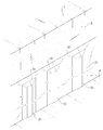
도 1은 일반적인 지하층의 보강벽 설치 상태를 나타내는 도면이다. 도 1을 참조하면, 1 is a view showing a reinforcement wall installation state of a typical basement floor. Referring to Figure 1,
(a)는 지하층 굴토에 따라, 지면(G)에서 하방으로 지하 부분이 형성되면서, 지하면(g)이 바닥에 위치되고, 이 지하면(g)에는 다양한 기초 구조, 집수정, 배수 시설들이 형성, 시공된다. 측방으로는 측벽(B)이 노출되는데, 이 측벽(B)에는 P와 같이 측방으로부터의 지하수에 의한 횡압력이 가해진다. 이러한 횡압력(P)은 건축물의 균열을 가져오거나, 파괴를 일으키게 되는데, 횡압력(P)에 대응하기 위하여 (b)와 같이, 측벽(B)측에 두꺼운 너비(W)의 보강벽(A)을 형성하여, 지지하는 방식을 사용한다.(a) is a basement part formed from the ground (G) down, according to the basement pit excavation, the basement (g) is located on the floor, the basement (g) has a variety of foundations, water wells, drainage facilities Formed and constructed. Sidewall B is exposed to the side, and lateral pressure by groundwater from the side is applied to sidewall B like P. As shown in FIG. This lateral pressure (P) is to cause a crack or breakage of the building, in order to correspond to the lateral pressure (P), as shown in (b), a thick width (W) of the reinforcement wall (A) on the side wall (B) side Forming and supporting method.
측방 횡압력(P)의 크기가 크고, 지하면(g)의 깊이가 깊어질 수록, 보강벽(A)의 두께(W)는 두꺼워 져야 하며, 이 공간을 마련하기 위해 지하층을 보다 넓게 파야 하는 문제점이 있고, 시공에 상당한 비용이 소요되는 문제점이 있다.
The larger the lateral lateral pressure (P) and the deeper the basement (g), the thicker the thickness (W) of the reinforcement wall (A) should be, and the more the basement should be dug to make room for this space. There is a problem that a considerable cost is required for construction.
도 2는 본 발명에 따른 배수 시스템이 형성된 상태를 나타내는 도면이다. 도 2를 참조하면, 본 발명은 측벽(B)의 외측면에, 측벽(B)을 향하여, 상하 방향으로 설치되며, 측벽(B)이 경사진 경우에는 측벽(B)을 따라 경사지게 형성된다.2 is a view showing a state in which a drainage system according to the present invention is formed. Referring to FIG. 2, the present invention is installed in the up and down direction toward the side wall B, on the outer side of the side wall B, and is inclined along the side wall B when the side wall B is inclined.
지하면(g)의 측벽(B)을 따라, 다수의 배수를 위한 구조가 형성되며, 도면에는 배수부재(미도시)에 감긴 토목섬유(20), 그 위를 각각 덮고 있는 커버부재(30), 넓은 범위에 걸쳐 덮고 있는 제2커버부재(40)를 설치한다. 이러한 설치는 지하층을 형성하기 위한 순타 공법, 역타 공법 모두에 적용이 가능하며, 측벽(B)의 외면에 설치되기만 하면, 가로, 세로 등 다양한 방향, 조합, 배치로 구성될 수 있다.
Along the sidewall (B) of the basement (g), a structure for a plurality of drainage is formed, the
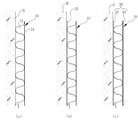
도 3은 본 발명에 따른 배수 시스템 형성 과정의 실시예를 나타내는 도면이다. 도 3을 참조하면, (a)는 측벽(B)에 배수부재(10)를 바로 설치한 상태를 나타낸다. 배수부재(10)로는 드레인보드, 드레인매트, 다발관, 관, 배수판, 중공관, 호스, 플라스틱관, 거푸집, 유공관 또는 무공관 등 다양하게 구성될 수 있으며, 그 재질 역시 목재, 합성수지, 콘크리트 블록 또는 스티로폼 등 다양하게 선택할 수 있다. 즉 측벽(B)과의 사이에 지하수가 유입되어 하측으로 흐를 수 있는 빈 공간을 형성할 수 있는 구성이라면 제한없이 사용이 가능한데, 통상 드레인보드를 사용한다. 드레인보드는 도면과 같이 돌출부(12) 및 판부(14)를 구비하여, 돌출부(12)에 의해 판부(14)의 하면(도면상 좌측면)에 형성되는 공간이 측벽(B)으로부터의 지하수가 유입되어 하방으로 흐르는 경로가 된다.3 is a view showing an embodiment of a process for forming a drainage system according to the present invention. Referring to FIG. 3, (a) shows a state in which the
이 때 측벽(B)으로부터 유입되는 지하수의 이물질을 차단하기 위해 (a)와 같이 측벽(B)쪽에 토목섬유(22)를 구비하여 필터의 역할을 하도록 하는 것이 바람직하다. 토목섬유는 통상 건설현장에서 사용되는 부직포 등을 사용한다.At this time, in order to block foreign substances in the groundwater flowing from the side wall (B), it is preferable to have a geotextile 22 on the side wall (B) as shown in (a) to act as a filter. Geotextiles generally use non-woven fabrics used in construction sites.
토목섬유(20)는 (c)와 같이 배수부재(10)의 외면을 감싸서, 전면에 토목섬유(22)가 위치되는 동시에, 후면에도 토목섬유(24)가 위치되도록 하는 것도 가능하다. 토목섬유(20)는 현장에서 측벽(B)쪽에 고정시키고, 그 외측에 배수부재(10)를 설치시킬 수도 있고, 처음부터 배수부재(10)에 부착시킨 후에, 배수부재(10)와 함께 배치될 수도 있으며, 또는 배수부재(10)의 외측에 감긴 상태에서, 배수부재(10)와 함께 배치되는 것도 가능하다.The
토목섬유(20), 배수부재(10)는 측벽(B)을 향해, 못, 핀, 스테이플러, 테이프, 접착제 등으로 고정시키는 것이 바람직하다.
도 4는 본 발명에 따른 배수 시스템 형성 과정의 실시예를 평면으로 나타내는 도면이다. 도 4를 참조하면, (a)와 같이 측벽(B)을 향해 토목섬유(20)가 감긴 배수부재(10)가 배치되는데, (b)와 같이 그 외측에 커버부재(30)가 씌워질 수 있다. 커버부재(30)는 배수부재(10)보다 더 넓게 형성되어, 양측이 측벽(B)측에 밀착하여 고정시키는 것이 바람직하다. 커버부재(30)는 통상 PE필름, 비닐 등을 사용하며, 측벽(B)으로부터 유입된 지하수를 배수부재(10) 측으로 모아서 유도하는 역할을 한다. 즉 측벽(B)에서 유입된 지하수는 커버부재(30)로 인해 커버부재(30)를 따라 배수부재(10) 측으로 유도되고, 유도된 지하수는 토목섬유(20)를 지나 배수부재(10) 내측으로 이동되어 하방으로 빠져나가게 된다.4 is a plan view showing an embodiment of a process for forming a drainage system according to the present invention. Referring to Figure 4, as shown in (a) is arranged a
또한 커버부재(30)는 (c)와 같이 2겹 이상 설치하거나, 다수의 배수부재(10)를 덮도록 넓게 형성될 수도 있다. 즉, 각각의 배수부재(10)를 덮는 커버부재(30)를 형성하고, 그 외측에 다시 여러 배수부재(10) 및 커버부재(30)를 재차 덮는 제2커버부재(40)를 배치시켜, 보다 넓은 지역, 또는 전체 범위의 지역에 대한 지하수 유입을 배수부재(10) 측으로 유도하게 할 수 있다.
In addition, the
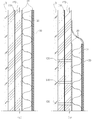
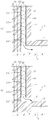
도 5는 본 발명에 따른 배수 시스템 형성 과정의 실시예를 측방에서 단면으로 나타내는 도면이고, 도 6은 본 발명에 따른 배수 시스템 형성 과정의 다른 실시예를 나타내는 도면이다. 도 5를 참조하면, 지하층 측벽(B)에는 와이어 메쉬라 불리는 철망 등 각종 망부재(110)를 배치하고, 그 위에 다시 숏크리트, 모르타르와 같은 시멘트 혼합물(120)을 타설하여 일정 두께로 형성한다.5 is a view showing an embodiment of the drainage system forming process according to the present invention in a cross-sectional view from the side, Figure 6 is a view showing another embodiment of the drainage system forming process according to the present invention. Referring to FIG. 5,
측벽(B)이 암반인 경우에는 배수부재(10)나 커버부재(30) 등을 설치하기가 까다로운데, 와이어 메쉬를 치고, 숏크리트를 타설한 경우에는, 보다 설치가 용이하게 된다. 시멘트 혼합물(120)는 직접 바르거나, 또는 펌프장치로 뿌리는 방식을 사용할 수 있는데, 이를 포함한 시멘트 혼합물층(120) 형성 방법을 타설이라고 표현하도록 한다.When the side wall B is a rock, it is difficult to install the
시멘트 혼합물층(120)이 타설되어 형성된 후에는, 전술한 바와 같은 다양한 실시예의 배수부재(10), 토목섬유(20), 커버부재(30)를 배치시키도록 하며, 이 때 (b)와 같이 시멘트 혼합물층(120)의 중간 중간에 통공(130)을 미리 형성해 놓는 경우에는, 보다 원활한 지하수의 집수가 가능해 진다.After the
도 6을 참조하면, 먼저 시멘트 혼합물층(120)에 다수의 통공(130)을 형성시켜 놓고, 그 위에 배수부재(10), 토목섬유(20), 커버부재(30) 등을 배치하도록 할 수 있다.
Referring to FIG. 6, first, a plurality of through
도 7은 본 발명에 따른 배수 시스템의 다른 실시예를 나타내는 도면이다. 도 7을 참조하면, 본 발명의 배수 시스템은 다양한 측벽 보강 구조에 사용될 수 있다. (a)와 같이 지하층 측벽(B)에 H빔(210)과 토류판인 차단부재(220)를 쌓는 방식의 흙막이 공법에도 사용이 가능하고, (b)와 같이 콘크리트파일(310, 330)과 H빔(320)을 통해 흙막이 벽체를 형성하는 CIP 공법에서도 측벽(B)면 상에 설치가 가능하다.
7 shows another embodiment of a drainage system according to the invention. Referring to Figure 7, the drainage system of the present invention can be used in various sidewall reinforcement structures. As shown in (a), it is also possible to use the earthquake method of stacking the
도 8은 본 발명에 따른 배수 시스템의 하단 연결 구조에 대한 실시예를 나타내는 도면이다. 도 8을 참조하면, 본 발명의 배수 시스템 하단은 배수부재(20)를 따라 하방으로 흐른 지하수가 배출될 수 있도록, (a)와 같이 바닥층 하면에 형성된 영구 배수 시스템(D)에 연결되도록 하여, 화살표 방향과 같이 측면 벽에서 유입된 물을 하방으로 빼낼 수 있도록 하는 것이 가능하다. 영구 배수 시스템(D)은 별도의 집수정(미도시)과 연결되어, 지하층 하면의 상향 수압을 제거하기 위한 배수 구조이다.8 is a view showing an embodiment of the bottom connection structure of the drainage system according to the present invention. Referring to FIG. 8, the bottom of the drainage system of the present invention is connected to the permanent drainage system D formed on the bottom of the bottom layer as shown in (a) so that the groundwater flowing downward along the
또한 (b)와 같이, 보강벽(A)을 지나 지하 주차장 등의 지하실(C) 측 코너에 형성된 트렌치(T) 측으로 연결시켜, 화살표 방향과 같이 물을 트렌치로 배수시킬 수도 있다.
In addition, as shown in (b), water can be drained to the trench as shown in the direction of the arrow by passing through the reinforcing wall A to the trench T side formed in the corner of the basement C side such as an underground parking lot.
도 9는 본 발명에 따른 배수 시스템의 형성을 통해 지하층 보강벽을 얇게 형성할 수 있는 상태를 설명하기 위한 도면이다. 도 9를 참조하면, (a)는 별도의 측벽 배수 시스템이 없는 상태를 나타내는 것이고, (b)는 본 발명의 배수 시스템이 구비된 상태를 나타내는 것이다.9 is a view for explaining a state in which the basement reinforcement wall can be formed thin through the formation of the drainage system according to the present invention. Referring to Figure 9, (a) shows a state without a separate side wall drain system, (b) shows a state with a drain system of the present invention.
측방으로부터의 지하수 횡압력(P1)에 대해, 본 발명의 배수 시스템은 지하수를 적절히 배수될 수 있도록 함으로써, 그 압력의 크기가 P2와 같이 상대적으로 감소하게 된다. 이에 따라, 보강벽의 두께도 기존에는 넓은 두께(W1)의 보강벽(A1)으로 설치하여야 하던 것으로, 본 발명의 배수 시스템을 설치한 후에는 상대적으로 얇은 두께(W2)의 보강벽(A2)을 설치해도 되게 함으로써, 감소한 두께만큼의 굴토 범위가 감소되고, 그 만큼의 시공 재료 및 시공 기간이 감소되는 효과가 있게 된다.
For the groundwater lateral pressure P1 from the side, the drainage system of the present invention allows the groundwater to be drained properly, so that the magnitude of the pressure is relatively reduced, such as P2. Accordingly, the thickness of the reinforcement wall was also conventionally required to be installed as a reinforcement wall A1 having a wide thickness W1. After the installation of the drainage system of the present invention, the reinforcement wall A2 having a relatively thin thickness W2 is provided. By allowing the to be provided, the gulting range by the reduced thickness is reduced, and the construction material and the construction period by that amount are reduced.
도 10은 본 발명의 다른 실시예에 따른 배수부재를 나타낸 도면이다. 도 10을 참조하면, 기존의 드레인보드를 배수부재로 사용할 수 있음은 물론, 도면과 같이 상측 하측 모두 개방될 수 있도록, 분리되는 상방접촉부(36)와 하방접촉부(38)를 구비한 배수부재를 사용할 수도 있다.10 is a view showing a drain member according to another embodiment of the present invention. Referring to Figure 10, as well as the existing drain board can be used as a drain member, as shown in the drawing so that both the upper side and the lower side, the drain member having a separate
또한, 이러한 배수부재를 활용하여, 도 12와 같이 지하면(g)의 상측에 수평 방향의 영구 배수로를 형성할 수도 있다. 이 때 배수부재는 드레인보드를 사용하거나, 후술할 도 10의 배수부재를 사용하는 것이 가능하다. 배수부재(10)의 저면 또는 둘레에는 토목섬유(22)를 깔거나 감고, 그 외측에 커버부재(30)인 PE필름 등을 덮은 후에, 콘크리트 혼합물을 부어 상측에 콘크리트층(E)을 형성하여 내측으로 배수 공간을 형성하도록 한다. 또한 이러한 수평의 배수부재는 후술하는 바와 같이 일정 높이 상측으로 상승했다 하강하는 감압관 내지는 감압경로를 구비함으로써, 일정 높이까지의 수압에 대해서 감압 기능을 수행하도록 하는 것도 가능하다.In addition, by utilizing such a drain member, it is also possible to form a permanent drain in the horizontal direction above the ground (g) as shown in FIG. In this case, the drain member may use a drain board or a drain member of FIG. 10 to be described later.
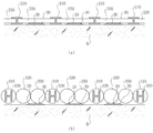
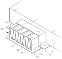
판형 배수부재는 전체적으로 직육면체의 외곽 형상을 띄고 있으며, 상면은 폐쇄된 판형의 상방접촉부(36)가 장형으로 형성되어 있고, 그 하방으로는 길이 방향으로 일정 간격 나란히 형성된 판 형태의 지지부(32, 34)들이 다수 개 연장 형성되어 있다. 지지부(32, 34)의 하단부에는 수평한 방향으로 면 형성되어 바닥면에 접촉되는 부분인 하방접촉부(38)가 형성되어 있다.The plate-shaped drainage member has an outer shape of a rectangular parallelepiped as a whole, and its upper surface has a closed
다수의 지지부(32, 34)의 하방접촉부(38) 사이사이에는 빈 공간이 형성되는데, 그 부분을 개방부라 하며, 개방부를 통해서 지하면 하측이나 측벽에서 솟아나는 지하수를 내측으로 유입시킬 수 있도록 하는 역할을 한다. 또한 상방접촉부(36)의 하측과 하방접촉부(38) 사이사이의 공간이 형성하는 빈 공간부는 배수부라 칭하며, 배수부를 통해서 지하수가 흐를 수 있게 된다. 이러한 판형 배수재는 전체를 일체로 합성수지, 플라스틱 등으로 형성하는 것이 바람직하며, 경우에 따라서는 시멘트 혼합물이나 금속으로 형성할 수도 있다.An empty space is formed between the
상방접촉부(36)와 하방접촉부(38)는 판형으로 형성되고 길게 형성되며, 다수개가 서로 간격을 이루도록 각각 상측 및 하측에 구비한다. 그 사이에는 개방부가 형성되도록 하여 상방 또는 하방으로부터의 물 유입이 가능하도록 하는 역할을 한다. 이 경우 상하측 모두로부터 물 유입이 가능하게 되는데, 경우에 따라서는 상방접촉부(36)는 크게 하나만 두고(미도시), 하방접촉부(38)는 다수로 두어, 상측은 폐쇄되고, 하측만 개방됨으로써 하방으로부터만 물 유입이 가능하도록 하는 것도 가능하다.The
지지부(32, 34)는 상방접촉부(36)와 하방접촉부(38)의 사이에 일체로 연결형성되는데, 도면과 같이 좌우측 단부에는 수직형의 수직지지부(32)가 구비되고, 중앙 부분에는 반복되는 V 형의 경사를 이루도록 경사지지부(34)가 다수 구비되며, 상방접촉부(36)와 하방접촉부(38)를 상호 연결하고, 그 사이의 공간이 배수로로 활용될 수 있도록 하는 것이 바람직하다.The
경사지지부(34)는 좌우측에서 상호 대칭시키는 하중의 전달 경로로 인해, 콘크리트 타설시 높은 하중에 의한 좌굴을 방지할 수 있는 역할을 하며, 상방접촉부(36)와 하방접촉부(38)는 외측에 감기는 토목섬유(미도시)가 함몰되는 것을 방지하는 역할을 한다. 물론 외측에 감기는 토목섬유(부직포)는 현장 상황에 따라서 사용하지 않고, 직접 판형 배수재를 설치할 수도 있으며, 이는 다른 실시예들에서도 동일하다.The
또한, 좌우 양단부는 수직지지부(32) 및 경사지지부(34)와 상방 또는 하방접촉부(36, 38)가 직각삼각형을 포함하며 일체 구성되도록 함으로써, 이 부분을 통해 상하방으로부터의 강한 수압 및 콘크리트 압력을 지지해 낼 수 있도록 하는 것이 바람직하다. 물론 수직지지부(32)와 경사지지부(34) 사이의 공간을 동일 재질로 채워 넣을 수도 있으며, 또는 각각 분리 구성할 수도 있다.
In addition, the left and right end portions of the
도 11을 참조하면, 본 발명은, 양측에서 잡아당기거나 또는 양측에서 밀어 넣음에 따라서, 그 폭이 자유자재로 변할 수 있다. 즉, 판형 배수재의 재질이 합성수지 또는 금속으로 구성되므로, 어느 정도의 탄력성이 있고, 유동적이므로, 판형 배수재가 삽입되는 소켓의 너비가 좁은 경우에는 양쪽에서 내측으로 내입시켜 폭을 줄여 꽂을 수 있도록 하고, 소켓의 너비가 넓거나 설치 위치에 넓게 배치하여야 하는 경우에는, 이를 양쪽으로 넓게 벌려서 보다 넓은 배수 구간을 확보할 수 있도록 하는 것이 가능하다. 또한 물 유입량을 결정할 수도 있게 되는데, 높은 물유입량이 필요한 경우에는 판형 배수재를 최대한 양쪽으로 벌려서 설치를 하면 되고, 낮은 물 유입량으로 유지하고자 하는 경우에는 판형 배수재를 내측으로 좁혀서 설치를 할 수 있게 된다. 이러한 너비 조절 특징은 종래의 S형 다발관이나 통상의 드레인보드에서는 달성이 불가능한 것으로서, 특유의 효과가 있다고 할 것이다.
Referring to FIG. 11, the width of the present invention may vary freely by pulling on both sides or pushing on both sides. That is, since the material of the plate drainage is made of synthetic resin or metal, it is flexible and flexible to some extent, so that the width of the socket into which the plate drainage is inserted is narrow, so that the width of the plate drainage can be reduced from the inside to both sides. If the width of the socket is to be wide or to be placed in the installation position, it is possible to spread it wide to both sides to ensure a wider drainage section. In addition, it is possible to determine the inflow of water, if a high water inflow is required to install the plate drainage spread to both sides as possible, if you want to maintain a low water inflow can be installed by narrowing the plate drainage to the inside. Such a width adjustment feature is impossible to achieve in the conventional S-shaped bundle tube or a conventional drainboard, and will have a unique effect.
한편, 지하 수평의 굴토마감면 상에 수평하게 배치되는 배수부재의 경우, 집수정이나 외부 배수 공간까지 이르는 도중에, 일정 높이를 갖도록 상측으로 연장되었다가 다시 하측으로 내려오도록 하는 경로가 형성되도록 할 수도 있다. 즉, 도 13과 같이, 상방을 향하는 상방경로(16)와 그 상단에서 연결되는 하방경로(18)를 갖도록 본 발명의 배수구조를 적절하게 결합시킬 수 있을 것이며, 상방경로 및 하방경로는 별도의 관을 연결하여 사용하거나 U자형 관을 사용하거나, 드레인보드를 U형으로 꺾어서 사용하거나, 전술한 도 10의 배수부재를 꺾어 사용하거나, 결합, 연결시켜 사용하는 것이 가능하다.
On the other hand, in the case of the drain member disposed horizontally on the underground horizontal gulto finish surface, the path to extend to the upper side to have a certain height and down to the lower side on the way to the sump or the external drainage space may be formed have. That is, as shown in Figure 13, it will be able to properly combine the drainage structure of the present invention to have an
한편, 본 발명은 전술한 전형적인 바람직한 실시 예에만 한정되는 것이 아니라 본 발명의 요지를 벗어나지 않는 범위 내에서 여러 가지로 개량, 변경, 대체 또는 부가하여 실시할 수 있는 것임은 당해 기술분야에서 통상의 지식을 가진 자라면 용이하게 이해할 수 있을 것이다. 이러한 개량, 변경, 대체 또는 부가에 의한 실시가 이하의 첨부된 특허청구범위의 범주에 속하는 것이라면 그 기술사상 역시 본 발명에 속하는 것으로 보아야 한다.
On the other hand, the present invention is not limited to the above-described typical preferred embodiment, it can be carried out in various ways without departing from the gist of the present invention various modifications, changes, substitutions or additions in the art Anyone who has this can easily understand it. It is to be understood that the invention is not limited to the disclosed embodiments, but, on the contrary, it is intended to cover various modifications within the scope of the appended claims.
G : 지면 g : 지하면
A : 보강벽 B : 측벽
P : 측방수압 10 : 배수부재
12 : 돌출부 14 : 판부
20 : 토목섬유 30 : 커버부재
40 : 제2커버부재 110 : 망부재
120 : 시멘트 혼합물 130 : 통공
210 : H빔 220 : 차단부재
310 : 콘크리트 파일 320 : H빔
330 : 콘크리트 파일G: Ground g: Underground
A: reinforcement wall B: side wall
P: Lateral water pressure 10: Drainage member
12: protrusion 14: plate
20: geotextile 30: cover member
40: second cover member 110: network member
120: cement mixture 130: through hole
210: H beam 220: blocking member
310: concrete pile 320: H beam
330: Concrete File
Claims (13)
(2) 배수부재를 상기 지하면 상에 배치하는 단계;
(3) 상기 배수부재를 배수로 또는 집수정 측으로 연결시켜 상기 배수부재로부터 유입되는 물을 상기 배수로 또는 상기 집수정으로 배출시킬 수 있도록 하는 단계;를 포함하여 구성되고,
상기 (2) 단계 후에, 상기 지하면에 시멘트 혼합물을 타설하는 단계를 더 포함하는 것을 특징으로 하는 지하층 배수 시스템 형성 방법.
(1) forming an underground portion below the ground, an underground surface of the bottom, and sidewalls on the side;
(2) disposing a drain member on the ground surface;
(3) connecting the drain member to a drainage channel or the sump side to discharge the water flowing from the drain member into the drainage channel or the sump;
After step (2), further comprising the step of pouring a cement mixture on the basement.
상기 (2) 단계에서 상기 배수부재를 구비한 후에,
상기 배수부재의 외측으로, 상기 배수부재보다 넓게 커버부재를 배치시키는 것을 특징으로 하는 지하층 배수 시스템 형성 방법.
The method of claim 1,
After the drain member is provided in the step (2),
And a cover member disposed outside the drainage member than the drainage member.
상기 배수부재는 다수개가 배치되고,
상기 다수개의 배수부재의 외측에 각각 다수의 상기 커버부재가 배치되고,
상기 다수개의 배수부재 및 상기 다수개의 커버부재의 외측에는 제2커버부재가 더 배치되는 것을 특징으로 하는 지하층 배수 시스템 형성 방법.
The method of claim 2,
The drain member is disposed a plurality,
A plurality of the cover member is disposed on the outside of the plurality of drain members, respectively
And a second cover member is further disposed outside the plurality of drain members and the plurality of cover members.
(2) 배수부재를 상기 측벽 상에 배치하는 단계;
(3) 상기 배수부재를 배수로 또는 집수정 측으로 연결시켜 상기 배수부재로부터 유입되는 물을 상기 배수로 또는 상기 집수정으로 배출시킬 수 있도록 하는 단계;를 포함하여 구성되는 것을 특징으로 하는 지하층 배수 시스템 형성 방법.
(1) forming an underground portion below the ground, an underground surface of the bottom, and sidewalls on the side;
(2) disposing a drain member on the side wall;
(3) connecting the drainage member to the drainage channel or the sump side to discharge the water flowing from the drainage member to the drainage path or the sump well; forming an underground layer drainage system, characterized in that it comprises a .
상기 (2) 단계에서, 상기 배수부재는 상기 측벽에 상하 방향으로 구비되는 것을 특징으로 하는 지하층 배수 시스템 형성 방법.
The method of claim 4, wherein
In the step (2), the drain member is formed in the basement floor drainage system, characterized in that provided in the vertical direction on the side wall.
상기 (2) 단계에서 상기 배수부재를 구비한 후에,
상기 배수부재의 외측으로, 상기 배수부재보다 넓게 커버부재를 배치시키는 것을 특징으로 하는 지하층 배수 시스템 형성 방법.
The method of claim 4, wherein
After the drain member is provided in the step (2),
And a cover member disposed outside the drainage member than the drainage member.
상기 배수부재는 다수개가 배치되고,
상기 다수개의 배수부재의 외측에 각각 다수의 상기 커버부재가 배치되고,
상기 다수개의 배수부재 및 상기 다수개의 커버부재의 외측에는 제2커버부재가 더 배치되는 것을 특징으로 하는 지하층 배수 시스템 형성 방법.
The method according to claim 6,
The drain member is disposed a plurality,
A plurality of the cover member is disposed on the outside of the plurality of drain members, respectively
And a second cover member is further disposed outside the plurality of drain members and the plurality of cover members.
상기 측벽과 상기 배수부재의 사이에 토목섬유가 배치되는 단계를 더 포함하거나,
상기 (2)단계에서, 상기 배수부재의 측벽측에 토목섬유가 구비되거나, 또는 상기 배수부재의 외측에 토목섬유가 감싸진 것을 사용하는 것을 특징으로 하는 지하층 배수 시스템 형성 방법.
The method of claim 4, wherein
Geotechnical fibers are disposed between the side wall and the drain member, or
In the step (2), geotextile is provided on the side wall side of the drainage member, or geotextile drainage system forming method characterized in that the use of the geotextile is wrapped around the outside of the drainage member.
상기 (1) 단계 후에, 상기 측벽에 시멘트 혼합물을 타설하는 단계를 더 포함하고, 상기 시멘트 혼합물이 타설된 후에 상기 (2) 단계가 진행되는 것을 특징으로 하는 지하층 배수 시스템 형성 방법.
The method of claim 4, wherein
After the step (1), the method further comprises the step of pouring a cement mixture on the sidewall, and the step (2) is performed after the cement mixture is poured.
상기 (1) 단계 후에, 상기 측벽과 나란히 망부재를 배치시키는 단계; 및
상기 철망을 향해 시멘트 혼합물을 타설하는 단계를 더 포함하고, 상기 시멘트 혼합물이 타설된 후에 상기 (2) 단계가 진행되는 것을 특징으로 하는 지하층 배수 시스템 형성 방법.
The method of claim 4, wherein
After the step (1), arranging the network member in parallel with the sidewall; And
And placing the cement mixture towards the wire mesh, wherein the step (2) is performed after the cement mixture is poured.
상기 (2) 단계 전에,
타설된 상기 시멘트 혼합물층에 통공을 형성하는 단계를 더 포함하는 것을 특징으로 하는 지하층 배수 시스템 형성 방법.
11. The method according to claim 9 or 10,
Before step (2) above,
And forming a through hole in the cement mixture layer that is poured.
상기 배수부재는:
장형의 판 형태로 형성되어 상측에 위치되는 다수의 상방접촉부;
장형의 판 형태로 형성되어 하측에 위치되는 다수의 하방접촉부;
상기 상방접촉부에 길이 방향을 따라 장형의 형상으로 하방을 향해 판 형태로 연장 형성되어 상기 하방접촉부와 연결되는 다수의 지지부;
상기 지지부들 사이에 형성되는 빈 공간으로 지하수가 흐를 수 있도록 하는 배수부; 및
상기 상방접촉부들 사이, 및 상기 하방접촉부들 사이에 형성되는 빈 공간인 개방부;를 포함하여 구성되는 것을 특징으로 하는 지하층 배수 시스템 형성 방법.
The method according to claim 1 or 4,
The drain member is:
A plurality of upper contact parts formed in an elongated plate shape and positioned on an upper side thereof;
A plurality of downward contact parts formed in a long plate shape and positioned at a lower side thereof;
A plurality of support parts extending in a plate shape downward in a long shape along a longitudinal direction of the upper contact part and connected to the lower contact part;
A drain for allowing groundwater to flow into the empty space formed between the support parts; And
And an opening part which is an empty space formed between the upper contact parts and between the lower contact parts.
상기 배수부재는:
장형의 판 형태로 형성되어 상측에 위치되는 상방접촉부;
장형의 판 형태로 형성되어 하측에 위치되는 다수의 하방접촉부;
상기 상방접촉부에 길이 방향을 따라 장형의 형상으로 하방을 향해 판 형태로 연장 형성되어 상기 하방접촉부와 연결되는 다수의 지지부;
상기 지지부들 사이에 형성되는 빈 공간으로 지하수가 흐를 수 있도록 하는 배수부; 및
상기 하방접촉부들 사이에 형성되는 빈 공간인 개방부;를 포함하여 구성되는 것을 특징으로 하는 지하층 배수 시스템 형성 방법.The method according to claim 1 or 4,
The drain member is:
An upper contact portion formed in a long plate shape and positioned on an upper side thereof;
A plurality of downward contact parts formed in a long plate shape and positioned at a lower side thereof;
A plurality of support parts extending in a plate shape downward in a long shape along a longitudinal direction of the upper contact part and connected to the lower contact part;
A drain for allowing groundwater to flow into the empty space formed between the support parts; And
And an opening part which is an empty space formed between the lower contact parts.
Priority Applications (1)
| Application Number | Priority Date | Filing Date | Title |
|---|---|---|---|
| KR1020110022859A KR20120105192A (en) | 2011-03-15 | 2011-03-15 | Drainage system construction method |
Applications Claiming Priority (1)
| Application Number | Priority Date | Filing Date | Title |
|---|---|---|---|
| KR1020110022859A KR20120105192A (en) | 2011-03-15 | 2011-03-15 | Drainage system construction method |
Publications (1)
| Publication Number | Publication Date |
|---|---|
| KR20120105192A true KR20120105192A (en) | 2012-09-25 |
Family
ID=47112251
Family Applications (1)
| Application Number | Title | Priority Date | Filing Date |
|---|---|---|---|
| KR1020110022859A KR20120105192A (en) | 2011-03-15 | 2011-03-15 | Drainage system construction method |
Country Status (1)
| Country | Link |
|---|---|
| KR (1) | KR20120105192A (en) |
Cited By (1)
| Publication number | Priority date | Publication date | Assignee | Title |
|---|---|---|---|---|
| CN113944179A (en) * | 2021-10-31 | 2022-01-18 | 北京中岩大地科技股份有限公司 | Construction method of existing basement pumping drainage precipitation structure |
-
2011
- 2011-03-15 KR KR1020110022859A patent/KR20120105192A/en not_active Application Discontinuation
Cited By (1)
| Publication number | Priority date | Publication date | Assignee | Title |
|---|---|---|---|---|
| CN113944179A (en) * | 2021-10-31 | 2022-01-18 | 北京中岩大地科技股份有限公司 | Construction method of existing basement pumping drainage precipitation structure |
Similar Documents
| Publication | Publication Date | Title |
|---|---|---|
| KR100981258B1 (en) | The retaining wall block and the construction method of retaining wall with retaining wall block and geogrid | |
| KR100665984B1 (en) | The construction method of basement self drainage | |
| KR100753556B1 (en) | De-pressure drainage method and the system | |
| KR101045314B1 (en) | Retaining wall and construnction method of retaining wall | |
| KR101388870B1 (en) | Rainwater storaging facility and method for building the facility | |
| KR20090069480A (en) | Prestressed quay wall and construction method thereof | |
| KR100926694B1 (en) | Groundwater collection and drainage system of the substructure under the underground structure | |
| KR101757116B1 (en) | Reinforced Earth Retaining Wall Equipped with Water Inflow Prevention and Draining Water Function | |
| KR200433220Y1 (en) | Sump system | |
| KR100655384B1 (en) | Method of drain construction for basement | |
| KR100748607B1 (en) | The construction method of basement drainage having double drainage canals and the system | |
| KR20120105192A (en) | Drainage system construction method | |
| KR101235826B1 (en) | The method of constructing block for wall | |
| KR100655383B1 (en) | Method of drain construction for basement | |
| KR100326868B1 (en) | Drain Board and Drainage method using the same | |
| KR100665985B1 (en) | The construction method of basement self drainage | |
| KR100932106B1 (en) | Drainage sheet and drainage method using the same | |
| KR200434601Y1 (en) | Drain Board System Of Basement Floor Construction | |
| KR200433390Y1 (en) | The construction system of basement drainage having double drainage canals | |
| KR100905661B1 (en) | Connector and system for apparatus draining | |
| KR200408863Y1 (en) | The construction system of basement drainage having double drainage canals | |
| KR100666103B1 (en) | Convertible de-pressure drainage method and the system | |
| KR200413305Y1 (en) | Convertible de-pressure drainage system | |
| KR100556820B1 (en) | chamber for uplift reduction processing, and it's construction method | |
| KR100666102B1 (en) | Vertical type basement drainage system |
Legal Events
| Date | Code | Title | Description |
|---|---|---|---|
| A201 | Request for examination | ||
| E601 | Decision to refuse application |