KR20120094643A - Cutting machine available of back boring - Google Patents
Cutting machine available of back boring Download PDFInfo
- Publication number
- KR20120094643A KR20120094643A KR1020110014030A KR20110014030A KR20120094643A KR 20120094643 A KR20120094643 A KR 20120094643A KR 1020110014030 A KR1020110014030 A KR 1020110014030A KR 20110014030 A KR20110014030 A KR 20110014030A KR 20120094643 A KR20120094643 A KR 20120094643A
- Authority
- KR
- South Korea
- Prior art keywords
- spindle
- tool
- sub
- processing mechanism
- fixed
- Prior art date
Links
Images


Classifications
-
- B—PERFORMING OPERATIONS; TRANSPORTING
- B23—MACHINE TOOLS; METAL-WORKING NOT OTHERWISE PROVIDED FOR
- B23B—TURNING; BORING
- B23B39/00—General-purpose boring or drilling machines or devices; Sets of boring and/or drilling machines
- B23B39/28—Associations of only boring or drilling machines directed to a particular metal-working result
-
- B—PERFORMING OPERATIONS; TRANSPORTING
- B23—MACHINE TOOLS; METAL-WORKING NOT OTHERWISE PROVIDED FOR
- B23P—METAL-WORKING NOT OTHERWISE PROVIDED FOR; COMBINED OPERATIONS; UNIVERSAL MACHINE TOOLS
- B23P23/00—Machines or arrangements of machines for performing specified combinations of different metal-working operations not covered by a single other subclass
- B23P23/02—Machine tools for performing different machining operations
-
- B—PERFORMING OPERATIONS; TRANSPORTING
- B23—MACHINE TOOLS; METAL-WORKING NOT OTHERWISE PROVIDED FOR
- B23P—METAL-WORKING NOT OTHERWISE PROVIDED FOR; COMBINED OPERATIONS; UNIVERSAL MACHINE TOOLS
- B23P23/00—Machines or arrangements of machines for performing specified combinations of different metal-working operations not covered by a single other subclass
- B23P23/04—Machines or arrangements of machines for performing specified combinations of different metal-working operations not covered by a single other subclass for both machining and other metal-working operations
Landscapes
- Engineering & Computer Science (AREA)
- Mechanical Engineering (AREA)
- Physics & Mathematics (AREA)
- Optics & Photonics (AREA)
- Drilling And Boring (AREA)
Abstract
Description
본 발명은 백보링 가공이 가능한 절삭용 가공장치에 관한 것으로, 좀 더 구체적으로는 피가공물의 스핀들 측 가공면과 스핀들 반대측 가공면에 대한 각종 절삭가공이 수치제어에 의한 연속적인 자동 공정을 통해 수행될 수 있어 가공공정이 합리화되어 제조생산성이 향상되고, 절삭용 가공장치의 활용성이 증대되는 한편, 피가공물의 스핀들 반대측 가공면에 대한 백 보링(back boring) 작업, 백 카운터 보링(back counter boring) 작업, 백 카운터 싱킹(back counter sinking) 작업도 자동으로 원활하고 신속하게 수행될 수 있는 백보링 가공이 가능한 절삭용 가공장치에 관한 것이다.
The present invention relates to a cutting apparatus capable of back boring, and more particularly, various cutting operations for the spindle side and the opposite side of the spindle of the workpiece are performed through a continuous automatic process by numerical control. The manufacturing process can be rationalized to increase the productivity of production, increase the utility of the cutting machine, while back boring and back counter boring of the machining surface of the workpiece opposite the spindle. The present invention relates to a cutting machine capable of back boring, which can be performed smoothly and quickly, automatically and back counter sinking.
절삭가공은 금속 소재를 정해진 형상으로 성형하기 위한 기계가공법의 일종으로, 금속 소재의 불필요한 부분을 절삭하여 칩(chip)으로 제거하면서 금속 소재를 정해진 형상으로 가공하게 된다. 이와 같은 절삭가공은 선반(lathe), 보링 머신(boring machine), 드릴링 머신(drilling machine), 밀링 머신(milling machine) 등의 기계가공장치와, 바이트(bite), 보링 공구, 드릴, 밀링 커터 등의 각종 절삭 공구(cutting tool)를 구비하여 이루어진다. 그리고, 일반적인 절삭용 가공장치는 몸체인 베드(bed)의 상부에 주축대가 설치되고, 주축대에 구비되어 전동기에 의해 회전하는 주축인 스핀들(spindle)의 선단부에 절삭 공구가 고정된 상태에서 베드 상에 고정되는 피가공물에 대한 절삭가공이 수행되도록 하는데, 스핀들의 선단부에 고정되는 절삭 공구는 필요시 형상, 크기, 종류를 달리하여 교체되어 사용된다. 여기서, 하나의 소재를 정해진 형상의 하나의 제품으로 제조할 시 다양한 절삭가공법이 적용될 수 있는데, 각 절삭가공법에 대응하여 다수종의 절삭용 가공장치를 구비하고, 각 절삭가공법에 대응하여 하나의 소재를 각각의 절삭용 가공장치로 이동시키는데 번거로움이 많으므로, 보링 머신, 드릴링 머신, 밀링 머신을 하나의 장치시스템으로 통합한 복합 가공장치인 머시닝 센터(machining center)가 개발되어 현재 사용되고 있다.
Cutting is a kind of machining method for forming a metal material into a predetermined shape, and the metal material is processed into a predetermined shape while cutting unnecessary portions of the metal material into chips. Such cutting processes include machining devices such as lathes, boring machines, drilling machines, milling machines, bites, boring tools, drills, milling cutters, and the like. It is made with a variety of cutting tools (cutting tools). In addition, a general cutting machine is installed in the upper head of the bed (bed), the main body is installed on the bed in the state in which the cutting tool is fixed to the front end of the spindle (spindle) which is provided on the main shaft to rotate by the electric motor The cutting is performed on the workpiece to be fixed to the cutting tool, the cutting tool fixed to the front end of the spindle is used is replaced by changing the shape, size, type, if necessary. Here, a variety of cutting methods may be applied when manufacturing one material into one product having a predetermined shape. A plurality of cutting devices may be provided corresponding to each cutting method, and one material may correspond to each cutting method. Since it is cumbersome to move the cutting machine to each cutting machine, a machining center, which is a complex machining device integrating a boring machine, a drilling machine and a milling machine into one device system, has been developed and is currently used.
머시닝 센터는 수치제어(NC:numerical control)에 의해 장치가 자동으로 구동되고, 자동공구교환대(ATC:automatic tool changer)가 구비되어 20?70개의 절삭 공구가 절삭조건에 따라 자동으로 교체되는데, 이에 따라 머시닝 센터는 가공공정의 자동화를 도모할 수 있게 된다. 즉, 머시닝 센터는 장치 구동전의 1회 공정설계 및 설정으로 다축 가공과, 다공정 가공이 자동으로 수행되도록 할 수 있다. 이와 같은 머시닝 센터와 관련한 기술로는 대한민국 등록특허 등록번호 제10-0982191호 "이중 스핀들 구조를 가지는 수평형 머시닝센터", 등록번호 제10-0816637호 "머시닝 센터의 공작물 자동 교환장치", 등록특허공보 등록번호 제10-0217948호 "머시닝 센터의 공구교환방법과 이를 수행하는 장치", 공개특허공보 공개번호 제10-2009-0055051호 "머시닝센터의 주축 결합구조", 등록실용신안공보 등록번호 제20-0426179호 "머시닝 센터의 척킹장치" 등이 안출되어 있다.
Machining centers are automatically driven by numerical control (NC) and equipped with an automatic tool changer (ATC), which allows 20 to 70 cutting tools to be replaced automatically according to cutting conditions. This allows the machining center to automate the machining process. That is, the machining center can automatically perform multi-axis machining and multi-process machining by one time process design and setting before driving the apparatus. As a technology related to such a machining center, Korean Patent Registration No. 10-0982191 "Horizontal Machining Center having a dual spindle structure", Registration No. 10-0816637 "Automatic workpiece exchanger of the machining center", registered patent Korean Patent Publication No. 10-0217948 "Method of changing a tool in a machining center and a device for performing the same", Korean Patent Publication No. 10-2009-0055051 "A spindle structure of a machining center", Registration Utility Model Publication No. No. 20-0426179, "Chucking Device of Machining Center" and the like.
도 1은 종래 머시닝센터에서 백보링 가공이 수행되는 공정을 보여주기 위한 도면이다.
1 is a view showing a process in which a back boring process is performed in a conventional machining center.
머시닝 센터에서의 절삭가공은 절삭 공구가 고정된 스핀들과 마주보는 피가공물의 스핀들측 가공면에 대해서 이루어지는데, 피가공물의 스핀들 반대측 가공면에 대한 절삭가공을 수행해야 할 경우, 이송기구를 사용하여 다수개의 직선경로를 따라 스핀들을 이동시켜 스핀들의 위치를 반전시키거나, 피가공물을 이동시켜 피가공물의 위치를 반전시켜야 했다. 이와 같은 스핀들의 위치 반전이나 피가공물의 위치 반전이 머시닝 센터를 이루는 장치에 의해 자동으로 수행될 수도 있으나, 위치조건에 따라 작업자가 직접 피가공물의 위치를 반전시켜야 하는 경우도 종종 발생하여 가공공정 상의 번거로움이 많았다. 특히, 피가공물의 홀(hole)에 대한 보링가공이 요구될 시 머시닝 센터는 보링 공구를 스핀들에 고정시켜 보링가공을 수행하게 되는데, 이 경우 머시닝 센터는 도 1의 (a)에서와 같이 스핀들과 마주보는 피가공물의 스핀들측 가공면(2a)에 대한 보링가공을 기본적으로 수행하게 된다. 그리고, 피가공물의 스핀들 반대측 가공면에 대한 보링가공을 수행할 경우, 먼저 머시닝 센터의 작동이 정지되도록 한다.
Machining at the machining center is carried out on the spindle side of the workpiece facing the spindle on which the cutting tool is fixed. If it is necessary to perform machining on the machining side opposite the spindle of the workpiece, use a feed mechanism. The spindles had to be moved along a number of straight paths to reverse the position of the spindles, or the workpieces had to be reversed. Such reversal of the spindle or reversal of the workpiece may be automatically performed by the device forming the machining center. However, depending on the location conditions, the operator often needs to reverse the position of the workpiece. There was a lot of trouble. In particular, when boring is required for the hole of the workpiece, the machining center performs the boring process by fixing the boring tool to the spindle. In this case, the machining center is connected to the spindle as shown in FIG. Basically, boring is performed on the spindle-
도 1의 (b)에서와 같이 스핀들 반대측에서 보링 공구(1a)의 생크(shank)(1b)가 피가공물(2)의 홀(3)을 통과하여 스핀들의 선단부에 고정되도록 하고, 생크(1b)의 끝단부에 보링 공구(1a)를 결합시켜 보링 공구(1a)가 피가공물(2)의 스핀들 반대측 가공면 상에 위치되도록 한다. 그리고, 스핀들을 후진시켜 보링 공구(1a)가 피가공물(2)의 스핀들 반대측 가공면(2b) 상에서 보링가공을 수행{이를 백 보링(back boring)으로 지칭함}하게 된다. 그러나, 상기와 같이 머시닝 센터의 작동이 정지되고, 작업자가 수작업으로 보링 공구를 스핀들 선단부에 고정시켜야 하는 번거로움이 있었다.
따라서, 종래 머시닝 센터는 피가공물의 스핀들 반대측 가공면에 대한 절삭가공 수행시 공정상의 번거로움이 많아 공정자동화가 이루어지지 않거나, 작업시간의 증대를 야기시켜 제조생산성과 가공효율이 낮아지게 됨에 따라, 이를 개선하는 기술의 개발이 현재 요구되고 있는 실정이라 하겠다.
Therefore, the conventional machining center has a lot of cumbersome process when performing machining on the machining surface opposite the spindle of the workpiece, so that the process automation is not performed or the increase of working time causes the manufacturing productivity and processing efficiency to decrease. Development of technology to improve this situation is currently required.
따라서 본 발명은 이와 같은 종래 기술의 문제점을 개선하여, 스핀들을 가진 메인 가공기구와 결합되어 스핀들 선단부로부터 이격된 위치에서 각종 공구를 스핀들 선단부에 고정시키게 되는 서브 가공기구의 구비로 피가공물의 스핀들 반대측 가공면에 대한 각종 절삭가공이 전후 가공공정에 연속해서 자동으로 수행될 수 있음에 따라, 공정 자동화가 극대화될 수 있는 새로운 형태의 백보링 가공이 가능한 절삭용 가공장치를 제공하는 것을 목적으로 한다.
Therefore, the present invention improves this problem of the prior art, and is provided with a sub-processing mechanism coupled to the main processing mechanism with a spindle to fix various tools to the spindle-end at a position spaced apart from the spindle-end, opposite the spindle side of the workpiece. It is an object of the present invention to provide a cutting apparatus capable of a new type of back boring process in which various types of cutting on the machining surface may be automatically performed continuously in the front and rear machining process, thereby maximizing the process automation.
특히, 본 발명은 서브 가공기구의 공구로 구비되는 보링 공구, 카운터 싱킹 공구가 피가공물의 스핀들 반대측 가공면의 외측에 위치되고, 보링 공구, 카운터 싱킹 공구의 생크(shank)가 피가공물의 가공면에 천공된 홀(hole)을 관통하여 스핀들의 선단부에 고정되면서 피가공물의 스핀들 반대측 가공면에 대한 절삭 가공이 수행됨에 따라, 피가공물에 대한 백 보링(back boring) 작업, 백 카운터 보링(back counter boring) 작업, 백 카운터 싱킹(back counter sinking) 작업이 자동으로 원활하고 신속하게 이루어질 수 있는 새로운 형태의 백보링 가공이 가능한 절삭용 가공장치를 제공하는 것을 목적으로 한다.
In particular, in the present invention, a boring tool and a counter sinking tool, which are provided as a tool of a sub-processing mechanism, are positioned outside the machining surface opposite to the spindle of the workpiece, and the shank of the boring tool and the counter-sinking tool is the machining surface of the workpiece. As the cutting process is performed on the machining surface opposite the spindle of the workpiece while penetrating the hole drilled in the hole, the back boring operation and the back counter of the workpiece are performed. It is an object of the present invention to provide a cutting machine capable of a new type of back boring, in which boring and back counter sinking operations can be performed smoothly and quickly.
또한, 본 발명은 서보 가공기구가 시계 방향이나 반시계 방향으로 회전하여 위치 반전되는 구성의 제공으로 피가공물의 위치변경없이 피가공물의 서로 다른 부위에 대한 절삭가공이 가능해지도록 함에 따라 가공공정의 효율이 증대될 수 있는 새로운 형태의 백보링 가공이 가능한 절삭용 가공장치를 제공하는 것을 목적으로 한다.
In addition, the present invention provides a configuration in which the servo machining mechanism is rotated in a clockwise or counterclockwise direction, thereby reversing the position, thereby enabling cutting of different portions of the workpiece without changing the position of the workpiece. It is an object of the present invention to provide a cutting machine capable of a new type of back boring process that can be increased.
상술한 목적을 달성하기 위한 본 발명의 특징에 의하면, 본 발명은 몸체프레임과; 상기 몸체프레임에 설치되고, 정해진 자유도운동을 수행하게 되는 이송기구와; 상기 이송기구 상에 위치되고, 스핀들용 액추에이터와 연결되어 회전하는 스핀들이 구비되며, 상기 스핀들의 선단부에 공구가 고정되도록 하는 메인 가공기구와; 상기 메인 가공기구와 결합되고, 공구가 결합고정되며, 결합고정된 공구가 상기 스핀들의 선단부에 고정되도록 하는 서브 가공기구 및; 상기 메인 가공기구로부터 이격된 위치의 몸체프레임에 설치되어 피가공물을 고정시키는 치구를 포함하여, 상기 서브 가공기구에 결합고정된 공구를 포함한 각종 공구가 상기 메인 가공기구의 스핀들에 고정되고, 상기 메인 가공기구가 상기 이송기구에 의해 이동하면서 상기 스핀들의 공구에 의해 상기 피가공물에 대한 절삭가공이 수행되도록 한다.
According to a feature of the present invention for achieving the above object, the present invention is a body frame; A transfer mechanism installed on the body frame and configured to perform a predetermined degree of freedom motion; A main machining mechanism located on the transfer mechanism, the spindle being connected to an actuator for the spindle, the main machining mechanism being fixed to the tip of the spindle; A sub-processing mechanism coupled with the main machining mechanism, the tool being coupled and fixed, and the coupled and fixed tool being fixed to the distal end of the spindle; Including a jig to be fixed to the workpiece to be installed on the body frame at a position spaced apart from the main machining tool, a variety of tools, including a tool fixed to the sub machining tool is fixed to the spindle of the main machining tool, the main The machining tool is moved by the transfer mechanism so that cutting of the workpiece is performed by the tool of the spindle.
이와 같은 본 발명에 따른 백보링 가공이 가능한 절삭용 가공장치에서 상기 서브 가공기구는 상기 스핀들의 중심축 연장선상에서 상기 스핀들의 선단으로부터 이격된 위치에 생크(shank)가 위치되면서 상기 공구가 고정되도록 하되, 상기 서브 가공기구는 상기 메인 가공기구에 고정되는 서브 액추에이터를 구비하여 상기 서브 액추에이터의 작동에 따라 상기 스핀들의 중심축 방향의 1자유도 운동을 수행하면서 상기 공구가 상기 스핀들의 선단부에 착탈되도록 한다.
In the processing apparatus for cutting back boring according to the present invention, the sub-processing mechanism allows the tool to be fixed while the shank is positioned at a position spaced apart from the distal end of the spindle on an extension line of the central axis of the spindle. The sub machining mechanism includes a sub actuator fixed to the main machining mechanism to allow the tool to be detached from the distal end of the spindle while performing one degree of freedom movement in the direction of the central axis of the spindle according to the operation of the sub actuator. .
이와 같은 본 발명에 따른 백보링 가공이 가능한 절삭용 가공장치에서 상기 메인 가공기구의 외주면 상에 설치되고, 회전체용 액추에이터의 작동에 따라 정해진 각도 범위에서 시계방향과 반시계방향 중에서 선택된 어느 방향으로 회전하게 되는 회전체가 더 구비되고, 상기 서브 가공기구는 상기 회전체에 고정되되, 상기 서브 가공기구가 상기 회전체와 일체로 정해진 각도만큼 회전하여 위치변경되면서 상기 피가공물의 위치변경없이 상기 피가공물의 서로 다른 부위에 대한 절삭가공이 가능해지도록 한다.
In the processing device for cutting back boring according to the present invention is installed on the outer circumferential surface of the main processing mechanism, in any direction selected from the clockwise and counterclockwise in a predetermined angle range in accordance with the operation of the actuator for the rotating body It is further provided with a rotating body to rotate, the sub-processing mechanism is fixed to the rotating body, the sub-processing mechanism is rotated by a predetermined angle integrally with the rotating body while changing the position without changing the position of the workpiece It allows cutting of different parts of the workpiece.
본 발명에 의한 백보링 가공이 가능한 절삭용 가공장치에 의하면, 스핀들을 가진 메인 가공기구와 결합되어 일체로 이동하되 스핀들로부터 이격된 위치에서 스핀들의 중심축 연장선상을 따라 직선이동하면서 보링 공구, 카운터 싱킹 공구 등의 공구를 스핀들 선단부에 착탈식으로 고정시키는 구성이 제공됨에 따라, 피가공물의 스핀들측 가공면과 스핀들 반대측 가공면에 대한 각종 절삭 작업이 연속적인 연속적인 수치제어 자동공정으로 수행될 수 있어 가공공정이 합리화되고, 이에 따라 제조생산성이 향상되는 효과가 있다. 이로써 소재에 대한 가공비가 절감됨에 따라 제품단가를 낮추어 가격경쟁력을 도모할 수 있는 효과도 동시에 가지게 된다. 특히, 본 발명의 백보링 가공이 가능한 절삭용 가공장치는 서브 가공기구의 공구로서 보링 공구나 카운터 싱킹 공구를 사용하므로써 피가공물의 스핀들 반대측 가공면에 대한 백 보링 작업, 백 카운터 보링 작업, 백 카운터 싱킹 작업이 자동으로 원활하고 신속하게 이루어지도록 한다. 이로써 백 보링 작업, 백 카운터 보링 작업, 백 카운터 싱킹 작업을 위한 별도의 번거로운 수작업이나 복잡한 공정설계가 요구되지 않아 가공 작업의 효율이 증대되는 효과를 가지게 된다. 또한, 본 발명에 의한 백보링 가공이 가능한 절삭용 가공장치는 머시닝센터에 적용되어 스핀들의 3축(X축, Y축, Z축) 이동, 스핀들에 고정되는 절삭공구의 자동교체, 백 보링 작업 및 백 카운터 싱킹 작업 수행 등을 통해 피가공물에 대해 절삭가공 전공정(total process)의 자동화를 도모할 수 있는데, 이로써 머시닝센터의 기능과 생산성을 극대화시킬 수 있게 된다. 그리고, 본 발명은 서브 가공기구 이동시 피가공물과의 간섭에 대응하여 서브 가공기구의 위치를 반전시키는 회전체를 구비함에 따라, 피가공물의 위치변경없이 피가공물의 서로 다른 부위에 대한 절삭가공을 연속적으로 수행할 수 있어 가공시간이 단축되고, 제조생산성이 더욱 향상되는 효과를 가지게 된다.
According to the cutting processing apparatus capable of back boring according to the present invention, a boring tool and a counter are combined with a main processing mechanism having a spindle, and are moved integrally, while linearly moving along a central axis extension of the spindle at a position spaced apart from the spindle. With the provision of detachable fixing of a tool such as a sinking tool to the spindle end, various cutting operations on the spindle side and the opposite side of the workpiece of the workpiece can be performed in a continuous continuous numerical control automatic process. The processing process is rationalized, whereby the manufacturing productivity is improved. As a result, the processing cost for the material is reduced, thereby lowering the unit cost and promoting price competitiveness. In particular, the back cutting tool capable of back boring of the present invention uses a boring tool or a counter sinking tool as a tool of a sub-processing tool, so that the back boring operation, the back counter boring operation, the back counter boring on the machining surface opposite the spindle of the workpiece Make sinking work smoothly and quickly automatically. This eliminates the need for a separate cumbersome manual or complicated process design for back boring, back counter boring and back counter sinking, thereby increasing the efficiency of machining. In addition, the cutting processing apparatus capable of back boring according to the present invention is applied to the machining center three-axis movement (X-axis, Y-axis, Z-axis) of the spindle, automatic replacement of the cutting tool fixed to the spindle, back boring operation And back counter sinking operations to automate the total cutting process for the workpiece, thereby maximizing the function and productivity of the machining center. In addition, the present invention includes a rotating body for reversing the position of the sub-processing mechanism in response to interference with the workpiece when the sub-processing mechanism is moved, thereby continuously cutting the workpieces on different parts of the workpiece without changing the position of the workpiece. It can be carried out by the processing time is shortened, it has the effect of further improving the manufacturing productivity.
도 1은 종래 머시닝센터에서 백보링 가공이 수행되는 공정을 보여주기 위한 도면;
도 2는 본 발명에 따른 백보링 가공이 가능한 절삭용 가공장치의 기본 구성을 보여주기 위한 블록도;
도 3은 본 발명에 따른 백보링 가공이 가능한 절삭용 가공장치를 이루는 메인 가공기구와 서브 가공기구의 주요부 구성을 보여주기 위한 개념도;
도 4는 본 발명에 따른 백보링 가공이 가능한 절삭용 가공장치에서 서브 가공기구의 공구가 스핀들의 척에 고정되는 구성을 보여주기 위한 개념도;
도 5는 본 발명에 따른 백보링 가공이 가능한 절삭용 가공장치에서 서브 가공기구가 회전체에 의해 위치가 반전되는 구성을 보여주기 위한 개념도;
도 6은 본 발명에 따른 백보링 가공이 가능한 절삭용 가공장치에 의해 절삭가공될 수 있는 피가공물의 실시예를 보여주기 위한 도면;
도 7은 본 발명의 실시예에 따른 백보링 가공이 가능한 절삭용 가공장치의 주요부 평면도;
도 8은 본 발명의 실시예에 따른 백보링 가공이 가능한 절삭용 가공장치의 주요부 측면도;
도 9와 도 10은 본 발명의 실시예에 따른 백보링 가공이 가능한 절삭용 가공장치를 이루는 메인 가공기구와 서브 가공기구의 주요부 상세 구성을 보여주기 위한 도면;
도 11은 본 발명의 실시예에 따른 백보링 가공이 가능한 절삭용 가공장치를 이루는 메인 가공기구와 서브 가공기구의 정면 구성을 보여주기 위한 도면;
도 12는 본 발명의 실시예에 따른 백보링 가공이 가능한 절삭용 가공장치를 이루는 메인 가공기구와 서브 가공기구의 후면 구성을 보여주기 위한 도면;
도 13은 본 발명의 실시예에 따른 백보링 가공이 가능한 절삭용 가공장치를 이루는 메인 가공기구와 회전체의 측면 구성을 보여주기 위한 사진이다.1 is a view for showing a process in which the back boring process is performed in a conventional machining center;
Figure 2 is a block diagram for showing the basic configuration of the cutting apparatus capable of back boring according to the present invention;
3 is a conceptual view showing the main parts of the main processing mechanism and the sub-processing mechanism forming a cutting device capable of back boring according to the present invention;
4 is a conceptual view illustrating a configuration in which a tool of a sub machining mechanism is fixed to a chuck of a spindle in a cutting apparatus capable of back boring according to the present invention;
5 is a conceptual view illustrating a configuration in which a sub-processing mechanism is reversed by a rotating body in a cutting apparatus capable of back boring according to the present invention;
Figure 6 is a view for showing an embodiment of the workpiece that can be cut by the cutting apparatus capable of back boring according to the present invention;
7 is a plan view of an essential part of a cutting apparatus capable of back boring according to an embodiment of the present invention;
8 is a side view of an essential part of a cutting apparatus capable of back boring according to an embodiment of the present invention;
9 and 10 are views for showing the detailed configuration of the main part of the main processing mechanism and the sub-processing mechanism constituting the cutting device capable of back boring processing according to an embodiment of the present invention;
11 is a view for showing the front configuration of the main processing mechanism and the sub-processing mechanism forming a cutting device capable of back boring according to an embodiment of the present invention;
12 is a view for showing the rear configuration of the main processing mechanism and the sub-processing mechanism constituting the cutting processing apparatus capable of back boring according to an embodiment of the present invention;
Figure 13 is a photograph for showing the side configuration of the main machining mechanism and the rotating body forming a cutting apparatus capable of back boring according to an embodiment of the present invention.
도 2는 본 발명에 따른 백보링 가공이 가능한 절삭용 가공장치의 기본 구성을 보여주기 위한 블록도이고, 도 3은 본 발명에 따른 백보링 가공이 가능한 절삭용 가공장치를 이루는 메인 가공기구와 서브 가공기구의 주요부 구성을 보여주기 위한 개념도이다.
Figure 2 is a block diagram for showing the basic configuration of the cutting apparatus capable of back boring processing according to the present invention, Figure 3 is a main processing mechanism and sub serving to form a cutting apparatus capable of back boring processing according to the present invention It is a conceptual diagram to show the configuration of main parts of the processing equipment.
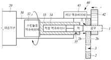
도 2와 도 3을 참조하면, 본 발명에 따른 백보링 가공이 가능한 절삭용 가공장치(100)는 몸체프레임(10), 이송기구(20), 메인 가공기구(30), 서브 가공기구(40), 치구(50)를 포함하는 구성으로 이루어지고, 메인 가공기구(30)의 스핀들(33)에 고정되는 각종 절삭용 공구(1)를 구비하여 드릴링, 밀링, 보링, 카운터 보링, 카운터 싱킹 등의 각종 절삭가공을 수행하게 된다. 특히, 피가공물(2)에 홀(hole)(3)이 형성되고, 메인 가공기구(30)와 일체로 결합되어 이동하는 서브 가공기구(40)로부터 메인 가공기구(30)의 스핀들(33)로 공구(1)가 피가공물(2)의 홀(3)을 통과하여 공급되면, 본 발명에 따른 백보링 가공이 가능한 절삭용 가공장치(100)는 백 보링(back boring), 백 카운터 보링(back counter boring), 백 카운터 싱킹(back counter sinking) 가공도 수행할 수 있게 된다. 여기서, 백-(back-)은 피가공물(2)의 스핀들 반대측 가공면(2b) 상에 공구(1)가 위치된 상태에서 스핀들(33)이 후진하여 공구(1)가 스핀들(33) 방향으로 이동하면서 이루어지는 가공을 지시하기 위하여 사용된 단어이다.
2 and 3, the
좀 더 구체적으로 보면, 몸체프레임(10)은 이송기구(20), 메인 가공기구(30), 서브 가공기구(40), 치구(50)가 고정설치되어 지지되는 기초 프레임으로서, 이와 같은 몸체프레임(10)으로는 일반적인 절삭용 가공장치의 베드(bed)가 사용될 수 있다.
In more detail, the
이송기구(20)는 몸체프레임(10)의 일측에 설치되는 것으로, 정해진 자유도운동을 수행하면서 메인 가공기구(30)를 이동시키게 된다. 이와 같은 이송기구(20)는 X축 방향 직선운동, Y축 방향 직선운동, Z축 방향 직선운동 중에서 선택된 1축 운동을 수행하거나, X축 방향 직선운동, Y축 방향 직선운동, Z축 방향 직선운동 중에서 선택된 2축 운동을 수행할 수도 있으나, X축 방향 직선운동, Y축 방향 직선운동, Z축 방향 직선운동의 3축 운동을 수행하는 구성으로 이루어지는 것이 바람직하다.
The
메인 가공기구(30)는 이송기구(20) 상에 위치되어 이송기구(20)에 의해 이동하게 되는 것으로, 이와 같은 메인 가공기구(30)는 스핀들용 액추에이터(32)와 연결되어 회전하는 스핀들(33)을 구비한다. 그리고, 스핀들(33)의 선단부에 공구(1)가 고정되는데, 스핀들(33)의 선단부에는 공구 고정을 위한 척(chuck)(35)이 스핀들(33)의 중심축 상에 설치되어 선단으로 돌출될 수 있다. 여기서, 척(35)은 척용 액추에이터(34)에 의해 직선이동하면서 공구물림용 장착공(36)의 크기를 조절하게 되는데, 이에 따라 절삭을 위한 각종 공구(1)가 척(35)에 고정되거나, 척(35)에 고정된 공구(1)가 척(35)으로부터 해제될 수 있게 된다. 이와 같이 구성되는 메인 가공기구(30)는 스핀들용 액추에이터(32)의 작동에 따라 스핀들(33)이 회전하고, 이송기구(20)의 작동으로 스핀들(33)이 메인 가공기구(30)와 일체로 일정 축방향으로 이동하면서 스핀들(33)의 선단부에 고정된 공구(1)가 피가공물(2)에 대한 각종 절삭가공을 수행하도록 한다. 여기서, 공구(1)는 머시닝 센터의 자동공구교환대(ATC)와 같이 절삭용 가공장치(100)에 구비되는 공구교환장치로부터 자동으로 공급되어 스핀들(33)의 선단부에 고정되거나, 작업자에 의해 수동으로 공급되어 스핀들(33)의 선단부에 고정될 수 있다. 또한, 공구(1)는 서브 가공기구(40)로부터 공급되어 스핀들(33)의 선단부에 고정될 수도 있다. 이와 같은 메인 가공기구(30)는 일반적인 절삭용 가공기구에 사용되는 주축대(head stock)가 사용될 수 있다.
The
서브 가공기구(40)는 메인 가공기구(30)와 결합되어 형성되는 것으로, 이와 같은 서브 가공기구(40)는 공구(1)가 결합고정된다. 여기서, 서브 가공기구(40)는 메인 가공기구(30)의 스핀들(33) 선단부 전방으로 이격된 위치에 공구(1)가 위치되어 결합고정되도록 한다. 그리고, 서브 가공기구(40)에 결합고정된 공구(1)의 생크(shank)는 스핀들(33)의 중심축 연장선상에 배치되도록 한다. 이와 같은 서브 가공기구(40)는 메인 가공기구(30)와 결합되어 메인 가공기구(30)와 일체로 이동하게 된다. 여기서, 서브 가공기구(40)는 메인 가공기구(30)에 고정되는 서브 액추에이터(43)를 구비하여 메인 가공기구(30)와 일체로 이동하는 것과는 별도의 독립적인 1자유도 운동을 수행할 수 있게 되는데, 이와 같은 서브 액추에이터(43)의 작동에 따라 스핀들(33)의 중심축 방향의 직선운동을 수행하면서 공구(1)의 생크가 스핀들(33)의 선단부에 착탈되도록 한다.
The
치구(jig and fixture)(50)는 메인 가공기구(30)로부터 이격된 위치의 몸체프레임(10)에 설치되어 피가공물(2)을 고정시키는 것으로, 이와 같은 치구(50)는 피가공물(2)이 고정시키는 기능만 가질 수도 있고, 필요시 고정된 피가공물(2)의 위치를 변경시키는 기능을 추가적으로 가질 수도 있다. 그리고, 치구(50)는 고정된 피가공물(2)의 가공면이 메인 가공기구(30)의 스핀들(33) 선단과 서브 가공기구(40)에 결합고정된 공구(1) 사이에 위치되도록 하여, 메인 가공기구(30)나 서브 가공기구(40)에 의해 절삭가공될 수 있도록 한다.
The jig and
이와 같은 본 발명에 따른 백보링 가공이 가능한 절삭용 가공장치(100)는 서브 가공기구(40)에 결합고정된 공구(1)를 포함한 각종 절삭용 공구(1)가 메인 가공기구(30)의 스핀들(33)에 고정되고, 치구(50)에 고정된 피가공물(2)이 메인 가공기구(30)와 서브 가공기구(40) 사이에 배치된 상태에서 메인 가공기구(30)가 이송기구(20)에 의해 이동하면서 스핀들(33)의 공구(1)에 의해 피가공물(2)에 대한 절삭가공이 수행되도록 한다.
Such a
도 4는 본 발명에 따른 백보링 가공이 가능한 절삭용 가공장치에서 서브 가공기구의 공구가 스핀들의 척에 고정되는 구성을 보여주기 위한 개념도이다.
4 is a conceptual view illustrating a configuration in which a tool of a sub machining mechanism is fixed to a chuck of a spindle in a cutting apparatus capable of back boring according to the present invention.
도 4를 참조하면, 본 발명에 따른 백보링 가공이 가능한 절삭용 가공장치(100)의 서브 가공기구(40)는 메인 가공기구(30)에 고정되는 서브 액추에이터(43)와, 서브 액추에이터(43)와 결합되어 메인 가공기구(30)의 스핀들(33) 선단 전방에 이격되게 배치되고 공구(1)가 결합고정되는 공구고정편(42)을 구비한다. 여기서, 서브 가공기구(40)에 결합고정된 공구(1)는 피가공물(2)의 스핀들 반대측 가공면(2b)에 위치되는데, 서브 액추에이터(43)의 구동에 따라 공구고정편(42)이 스핀들(33) 측으로 이동하게 되면 서브 가공기구(40)에 결합고정된 공구(1)의 생크는 피가공물(2)에 형성된 홀(3)을 통과하여 메인 가공기구(30)의 스핀들(33)에 형성된 척(35)에 삽입되고, 척용 액추에이터(34)에 의해 척(35)이 후진{스핀들(33)의 후단 방향으로 이동}하게 되면 척(35)의 공구물림용 장착공(36)의 크기가 작아지면서 공구(1)가 척(35)에 고정된다.
Referring to FIG. 4, the
이와 같이 서브 가공기구(40)에 결합고정된 공구(1)는 피가공물(2)의 스핀들 반대측 가공면(2b)에 위치된 상태에서 공구(1)의 생크가 스핀들(33)의 척(35)에 고정되어 스핀들(33)에 의해 회전하게 되는데, 이에 따라 피가공물(2)의 스핀들 반대측 가공면(2b)에 대한 절삭 가공을 수행할 수 있게 된다. 특히, 공구(1)로서 보링 공구(1a)나, 카운터 싱킹 공구가 사용될 경우 피가공물(2)의 스핀들 반대측 가공면(2b)에 대한 백 보링(back boring) 가공, 백 카운터 보링(back counter boring) 가공, 백 카운터 싱킹(back counter sinking) 가공이 수행될 수 있게 된다. 그리고, 척(35)에 고정된 서브 가공기구(40)의 공구(1)를 해제시킬 경우, 척용 액추에이터(34)를 구동하여 척(35)이 전진{스핀들(33)의 선단 방향으로 이동}되도록 하면 척(35)의 공구물림용 장착공(36)의 크기가 커지면서 공구(1)가 척(35)으로부터 해제되고, 서브 액추에이터(43)를 구동시켜 공구고정편(42)을 스핀들(33) 반대측으로 이동하게 되면 공구(1)가 척(35)으로부터 이탈되게 된다.
In this way, the
도 5는 본 발명에 따른 백보링 가공이 가능한 절삭용 가공장치에서 서브 가공기구가 회전체에 의해 위치가 반전되는 구성을 보여주기 위한 개념도이다.
5 is a conceptual view illustrating a configuration in which a sub-processing mechanism is reversed by a rotating body in a cutting apparatus capable of back boring according to the present invention.
도 5를 참조하면, 본 발명에 따른 백보링 가공이 가능한 절삭용 가공장치(100)는 회전체(60)를 더 구비할 수 있다. 이와 같은 회전체(60)는 메인 가공기구(30)의 외주면 상에 회전가능하게 설치되는 것으로, 회전체(60)에 서브 가공기구(40)가 고정설치된다. 이와 같은 회전체(60)는 회전체용 액추에이터의 작동에 따라 정해진 각도 범위에서 시계방향으로 회전하거나, 반시계방향으로 회전하게 되는데, 서브 가공기구(40)는 회전체(60)와 일체로 정해진 각도만큼 회전하여 위치를 변경시키게 된다. 여기서, 피가공물(2)에는 절삭 가공을 요하는 홀(3)이 다수개 형성될 수 있는데, 메인 가공기구(30)와 서브 가공기구(40)를 이용하여 서로 다른 부위에 형성되는 홀(3)을 연속해서 자동으로 절삭 가공할 시 메인 가공기구(30)와 서브 가공기구(40)가 서로 연결되는 부위가 피가공물(2)에 간섭되어 걸리게 되어 서로 다른 부위에 형성되는 홀(3)에 대한 연속적인 자동 절삭가공이 불가능할 수 있다. 이와 같은 경우, 피가공물(2)의 위치를 변경시켜야 하는데, 본 발명에 따른 백보링 가공이 가능한 절삭용 가공장치(100)는 회전체(60)를 이용하여 서브 가공기구(40)의 위치를 반전시키므로써 피가공물(2)의 위치변경없이 피가공물(2)의 서로 다른 부위의 홀(3)에 대한 연속적인 자동 절삭가공이 가능해지게 된다.
Referring to FIG. 5, the
도 6은 본 발명에 따른 백보링 가공이 가능한 절삭용 가공장치에 의해 절삭가공될 수 있는 피가공물의 실시예를 보여주기 위한 도면이다.
Figure 6 is a view for showing an embodiment of the workpiece that can be cut by the cutting apparatus capable of back boring according to the present invention.
도 6을 참조하면, 본 발명에 따른 백보링 가공이 가능한 절삭용 가공장치(100)는 끝단부에 카운터 보어(3a)나 카운터 싱크된 홀(3)을 가진 피가공물(2)을 제조할 수 있다. 특히, 본 발명에 따른 백보링 가공이 가능한 절삭용 가공장치(100)는 피가공물(2)의 끝단부 내측면 상에서 홀(3)에 카운터 보어(3a)나 카운터 싱크를 형성시킬 수 있다. 이와 같이 본 발명에 따른 백보링 가공이 가능한 절삭용 가공장치(100)에 의해 절삭가공되는 피가공물(2)로 도 6에 도시된 항공기 엔진의 터빈을 이루는 블레이드가 적용될 수 있다. 이와 같은 항공기 엔진 터빈용 블레이드는 엔진 터빈의 몸체 프레임에 고정되는데, 이를 위하여 몸체 프레임에 밀착되는 항공기 엔진 터빈용 블레이드의 끝단부위 내측면 상에는 카운터 보어되거나 카운터 싱크된 볼트공이 형성되어 체결볼트가 볼트공에 삽입되면서 항공기 엔진 터빈의 몸체프레임에 고정되도록 한다.
Referring to FIG. 6, the
이하, 본 발명의 실시예를 첨부된 도면 도 7 내지 도 14에 의거하여 상세히 설명한다. 한편, 도면과 상세한 설명에서 일반적인 공작기계, 절삭용 가공장치, 선반, 머시닝 센터, 보링 가공, 백보링 가공 등으로부터 이 분야의 종사자들이 용이하게 알 수 있는 구성 및 작용에 대한 도시 및 언급은 간략히 하거나 생략하였다. 특히 도면의 도시 및 상세한 설명에 있어서 본 발명의 기술적 특징과 직접적으로 연관되지 않는 요소의 구체적인 기술적 구성 및 작용에 대한 상세한 설명 및 도시는 생략하고, 본 발명과 관련되는 기술적 구성만을 간략하게 도시하거나 설명하였다.
Hereinafter, embodiments of the present invention will be described in detail with reference to FIGS. 7 to 14. On the other hand, in the drawings and detailed description showing and referring to the construction and operation easily understood by those skilled in the art from general machine tools, cutting equipment, lathes, machining centers, boring, back boring, etc. Omitted. In the drawings and specification, there are shown in the drawings and will not be described in detail, and only the technical features related to the present invention are shown or described only briefly. Respectively.
도 7은 본 발명의 실시예에 따른 백보링 가공이 가능한 절삭용 가공장치의 주요부 평면도이고, 도 8은 본 발명의 실시예에 따른 백보링 가공이 가능한 절삭용 가공장치의 주요부 측면도이다.
7 is a plan view of the main part of the cutting apparatus capable of back boring according to an embodiment of the present invention, Figure 8 is a side view of the main part of the cutting apparatus capable of back boring according to an embodiment of the present invention.
도 7과 도 8을 참조하면, 본 발명의 실시예에 따른 백보링 가공이 가능한 절삭용 가공장치(100)는 머시닝 센터에 적용되는 것으로, 특히 도 6에 도시된 항공기 엔진의 터빈을 이루는 블레이드와 같은 피가공물(2)에서와 같이 홀(3)에 대한 카운터 보링, 카운터 싱킹, 백 카운터 보링, 백 카운터 싱킹 가공이 요구되는 가공조건에 최적화되어 가공 공정의 자동화를 이루고, 제조생산성을 향상시키게 된다.
7 and 8, the
이와 같은 본 발명의 실시예에 따른 백보링 가공이 가능한 절삭용 가공장치(100)는 몸체프레임(10)을 이루는 베드(10a)에 이송기구(20), 메인 가공기구(30), 서브 가공기구(40), 치구(50)가 설치되어 이루어진다. 여기서, 베드(10a)는 하부에 다수개의 수평조절용 볼트(11)를 설치하여 이송기구(20), 메인 가공기구(30), 서브 가공기구(40), 치구(50)가 수평면 상에 설치될 수 있도록 한다.
The
이송기구(20)는 3축(X축, Y축, Z축) 상의 3자유도 운동을 수행하게 되는 것으로, 이를 위한 액추에이터(22)로서 X축 운동용 서보모터(22a), Y축 운동용 서보모터(22b), Z축 운동용 서보모터(22c)를 구비한다. 여기서, X축 운동용 서보모터(22a), Y축 운동용 서보모터(22b), Z축 운동용 서보모터(22c)는 볼스크류 모듈과 연동되어 구동되는데, 이송기구(20)의 이송바디(21)는 X축 운동용 서보모터(22a)와 Z축 운동용 서보모터(22c)에 의해 X축 운동과 Z축 운동을 수행하게 되고, 이송바디(21)에 고정된 Y축 운동용 서보모터(22b)와 연동되는 볼스크류 모듈에 메인 가공기구(30)가 설치되어 Y축 운동용 서보모터(22b)의 구동에 따라 메인 가공기구(30)의 Y축 운동이 유도된다.
The
메인 가공기구(30)는 이송기구(20) 상에 설치되는 것으로, 본 발명의 실시예에 따른 메인 가공기구(30)는 Y축 운동용 서보모터(22b)와 연동되는 볼스크류 모듈에 결합된다. 이와 같은 메인 가공기구(30)는 후단부에 스핀들용 액추에이터(32)로 사용되는 스핀들용 구동모터가 설치되고, 선단부에 스핀들(33)이 형성된다. 스핀들(33)의 선단부에는 공구물림용 장착공(36)을 형성한 척(35)이 배치되어 공구(1)가 고정될 수 있도록 한다.
The
서브 가공기구(40)는 메인 가공기구(30)와 연결되는 것으로, 본 발명의 실시예에 따른 서브 가공기구(40)는 메인 가공기구(30)의 외주면 상에 회전가능하게 결합되는 회전체(60)와 결합되어 메인 가공기구(30)와 연결된다. 이와 같은 서브 가공기구(40)는 스핀들(33)의 척(35) 선단으로부터 전방으로 이격된 위치에 형성되는 공구고정편(42)을 구비하고, 공구고정편(42)의 하단부에 공구(1)가 결합고정되는데, 공구고정편(42)에 고정되는 공구(1)는 생크가 스핀들(33) 방향으로 배치되도록 하여 스핀들(33)의 척에 물릴 수 있도록 한다.
치구(50)는 베드(10a)에 일정높이로 설치되어 피가공물(2)을 고정시키는 것으로 이와 같은 치구(50)는 클램프를 구비하여 피가공물(2)을 고정시키고, 이송장치를 구비하여 피가공물(2)을 X축, Y축, Z축 방향으로 이동시켜 고정된 피가공물(2)의 위치를 조정할 수 있다.
The
도 9와 도 10은 본 발명의 실시예에 따른 백보링 가공이 가능한 절삭용 가공장치를 이루는 메인 가공기구와 서브 가공기구의 주요부 상세 구성을 보여주기 위한 도면이고, 도 11은 본 발명의 실시예에 따른 백보링 가공이 가능한 절삭용 가공장치를 이루는 메인 가공기구와 서브 가공기구의 정면 구성을 보여주기 위한 도면이다.
9 and 10 are views for showing the detailed configuration of the main part of the main processing mechanism and the sub-processing mechanism forming a cutting device capable of back boring according to an embodiment of the present invention, Figure 11 is an embodiment of the present invention Figure 2 is a view showing the front configuration of the main processing mechanism and the sub-processing mechanism forming a cutting device capable of back boring according to.
도 9 내지 도 11을 참조하면, 본 발명의 실시예에 따른 메인 가공기구(30)는 주축대(31)의 내부에 베어링에 의해 지지되면서 회전가능하게 고정되는 스핀들(33)과, 스핀들(33) 내부에 직선이동 가능하게 고정되는 척(35)을 구비하는데, 척(35)은 주축대(31) 내부에 설치되는 척 구동실린더(34a)와 연결되어 직선이동하면서 공구물림용 장착공(36)의 크기를 축소하여 공구(1)를 고정시키거나 공구물림용 장착공(36)의 크기를 확대하여 고정된 공구(1)를 해제시키게 된다. 그리고, 메인 가공기구(30)의 주축대(31) 외주면 둘레를 따라 회전체(60)가 고정되는데, 이를 위하여 회전체(60)는 중공형 원통체 형상으로 이루어져 회전체(60)의 내주면과 주축대(31)의 외주면 사이에 베어링이 배치되도록 한다.
9 to 11, the
회전체(60)의 일단부 상측에는 서브 가공기구(40)의 고정체(41)가 회전체(60)와 일체로 결합되는데, 이와 같은 고정체(41)는 회전체(60)와 일체로 성형되거나, 별도로 구비되어 회전체(60)와 결합될 수 있다.
The upper end of the
서브 가공기구(40)의 고정체(41)는 정해진 길이와 두께를 가지는 블록체 형상으로 이루어질 수 있는데, 본 발명의 실시예에 따른 고정체(41)는 회전체(60)의 형상에 대응하여 부채꼴 형상으로 이루어지게 된다. 또한, 고정체(41)은 정해진 길이를 가지며 메인 가공기구(30)의 선단으로 돌출되어 있다. 이와 같은 고정체(41)는 서브 구동실린더(43a)와 가이드바(44)가 내부에 길이방향(Z축 방향)으로 설치되도록 한다.
The fixing
서브 구동실린더(43a)는 서로 일체로 이동하게 되는 메인 가공기구(30)와 서브 가공기구(40)와 독립적으로 공구고정편(42)을 Z축 방향으로 이동시키는 서브 액추에이터(43)로서, 서브 구동실린더(43a)에 작동에 따른 실린더로드의 확축에 따라 공구고정편(42)이 스핀들(33) 방향으로 이동하거나 스핀들(33) 반대방향으로 이동하게 된다. 이와 같은 서브 구동실린더(43a)의 고정체(41)의 중앙부에 설치된다.
The
가이드바(44)는 서브 구동실린더(43a)의 양측에 한쌍이 배치되는 것으로, 고정체(41)의 내부를 관통하여 Z축 방향으로 직선이동이 가능하게 고정체(41)에 설치된다. 이와 같은 가이드바(44)는 일단부가 공구고정편(42)과 결합되어 공구고정편(42)을 지지하게 되는데, 이에 따라 서브 구동실린더(43a)에 의한 공구고정편(42)의 Z축 방향 직선이동시 공구고정편(42)은 흔들림이나 형상변경없이 안정되게 이동을 수행할 수 있게 된다. 여기서, 서브 구동실린더(43a)의 실린더로드와 가이드바(44)는 실린더용 베어링(431)과 가이드바용 베어링(441)을 매개로 고정체(41)에 고정되어 원활한 직선이동이 도모될 수 있게 된다.
A pair of guide bars 44 are disposed on both sides of the
공구고정편(42)은 고정체(41)로부터 이격되게 배치되어 고정체(41)에 설치되는 서브 구동실린더(43a)와 가이드바(44)와 결합되는 것으로, 본 발명의 실시예에 따른 공구고정편(42)은 도 11에서와 같이 역삼각형 형상으로 이루어져 상부에는 고정체(41)에 설치되는 서브 구동실린더(43a)와 가이드바(44)가 결합되고, 하부에는 공구결합공(421)이 형성된다. 여기서, 공구고정편(42)이 역삼각형 형상으로 이루어짐에 따라, 스핀들(33)과 공구고정편(42) 사이에 배치되는 피가공물(2)과 공구고정편(42) 사이의 간섭이 최소화되게 된다.
The
공구고정편(42)의 하부에 형성된 공구결합공(421)에는 공구(1)가 고정되는데, 이를 위하여 공구결합공(421)에는 끝단부에 공구장착용 자석(451)을 형성한 공구장착구(45)가 삽입고정된다. 여기서, 공구장착구(45)의 공구장착용 자석(451)은 스핀들(33) 측에 배치된다. 이와 같은 공구장착구(45)의 공구장착용 자석(451)에 보링 공구(1a)와 같은 공구(1)가 장착되게 된다. 여기서, 공구장착구(45)는 공구결합공(421)에 베어링으로 지지되면서 회전가능하게 삽입고정되는데, 이에 따라 공구장착구(45)에 장착된 공구(1)의 생크가 스핀들(33)의 척(35)에 고정되고, 공구(1)가 스핀들(33)에 의해 회전하면서 피가공물(2)에 대한 절삭가공을 수행하게 될 시 공구(1)의 양단부가 스핀들(33)의 척(35)과 공구장착구(45)에 의해 동시에 지지됨에 따라 안정성이 향상되고 가공성의 증대를 도모할 수 있게 된다.
The
도 12는 본 발명의 실시예에 따른 백보링 가공이 가능한 절삭용 가공장치를 이루는 메인 가공기구와 서브 가공기구의 후면 구성을 보여주기 위한 도면이고, 도 13은 본 발명의 실시예에 따른 백보링 가공이 가능한 절삭용 가공장치를 이루는 메인 가공기구와 회전체의 측면 구성을 보여주기 위한 사진이다.
12 is a view showing a rear configuration of the main processing mechanism and the sub-processing mechanism forming a cutting device capable of back boring according to an embodiment of the present invention, Figure 13 is a back boring according to an embodiment of the present invention This is a picture to show the side configuration of the main processing mechanism and the rotating body forming the cutting device capable of processing.
도 12와 도 13을 참조하면, 본 발명의 실시예에 따른 백보링 가공이 가능한 절삭용 가공장치(100)는 주축대(31)의 외주면 상에 회전가능하게 고정되는 회전체(60)를 구비하게 되는데, 주축대(31)는 외주면 둘레 상에 180°의 각도로 이격되게 형성되는 걸림구(37)를 형성하고, 회전체(60)는 후단부에 걸림구(37)에 대응하는 스톱퍼형 센서(61)를 형성한다. 여기서, 걸림구(37)는 회전체(60)의 후측에서 스톱퍼형 센서(61)에만 간섭되도록 설치되는 것으로, 'L'형 단면 형상으로 이루어져 상측으로 돌출된 부위가 스톱퍼형 센서(61)와 간섭되게 된다. 스톱퍼형 센서(61)는 회전체(60)에 고정되어 회전체(60)와 일체로 회전하게 되는 것으로, 도 13에서와 같이 회전체(60)의 후측으로 돌출되게 형성된다.
12 and 13, the
이에 따라, 회전체(60)의 회전시 회전체(60)의 스톱퍼형 센서(61)는 주축대(31)의 걸림구(37)에 걸리게 되는데, 주축대(31)의 외주면 둘레 상에는 180°의 각도로 한쌍의 걸림구(37)가 이격형성됨에 따라, 회전체(60)는 180°의 각도범위 내에서 회전하게 된다. 여기서, 회전체(60)는 180°의 각도범위 내에서 다양한 각도로 회전할 수 있으나, 본 발명의 실시예에 따른 회전체(60)는 서브 가공기구(40)의 위치를 반전시키는 기능을 수행하므로, 180°만큼 시계방향 또는 반시계방향으로 회전하여 서브 가공기구(40)의 위치를 반전시키게 된다.{물론, 가공조건에 따라 걸림구(37)의 배치를 달리하여 회전체(60)의 회전각을 변경시킬 수도 있다.}
Accordingly, the stopper-
이와 같이 회전체(60)는 180°의 정해진 각도로만 회전함에 따라, 한쌍의 회전체 공압호스(62)로부터 교번되게 전달되는 공압으로 회전체(60)를 시계방향으로 회전시키거나 반시계방향으로 회전시키게 되는 공압실린더를 회전체용 액추에이터로 사용하게 된다. 이와 같이 회전체용 액추에이터의 공압실린더는 산업현장에서 활용되고 있는 중공형 회전 에어 실린더(rotary air cylinder)가 사용될 수 있다.
As the
상기와 같이 본 발명의 실시예에 따른 백보링 가공이 가능한 절삭용 가공장치(100)는 회전체(60)의 180°에 따라, 회전체(60)와 결합된 서브 가공기구(40)의 고정체(41) 위치가 상하방향(Y축 방향)으로 반전될 수 있고, 이로써 고정체(41)에 설치되는 서브 구동실린더(43a)와 가이드바(44)와 결합된 공구고정편(42)의 위치도 반전될 수 있게 된다.
As described above, the
이에 따라, 피가공물(2)의 하부에 배치되는 홀(3)에 대한 백 카운터 보링 가공이나 백 카운터 싱킹 가공도 피가공물(2)의 위치변경 없이 스핀들(33)의 이동 및 회전체(60)의 회전을 통한 공구고정편(42)의 위치변경을 통해 수행할 수 있게 된다. 즉, 피가공물(2)의 하부에 배치되는 홀(3)에 대한 백 카운터 보링 가공이나 백 카운터 싱킹 가공이 요구될 시 먼저, 메인 가공기구(30)를 피가공물(2)의 외측방향(X축 방향)으로 이동시켜 스핀들(33)과 서브 가공기구(40)이 피가공물(2)과 간섭되지 않도록 한다. 그리고, 회전체(60)를 180°회전시켜 공구고정편(42)의 위치를 반전시킨 후, 다시 메인 가공기구(30)를 피가공물(2) 방향으로 이동시켜 스핀들(33)과 서브 가공기구(40) 사이에 피가공물(2)이 배치되도록 하여 피가공물(2)의 하부에 배치되는 홀(3)에 대한 백 카운터 보링 가공이나 백 카운터 싱킹 가공이 수행될 수 있도록 한다. 여기서, 피가공물(2)의 하부에 배치되는 홀(3)이 피가공물(2)의 측방향 끝단부에 위치될 경우에는 회전체(60)를 곧바로 시계방향이나 반시계방향으로 180°회전시키도 피가공물(2)과 간섭되지 않으므로, 메인 가공기구(30)의 이동이 생략될 수 있다. 이와 같은 메인 가공기구(30)의 이동 공정이나 회전체(60)의 회전 공정은 수치제어에 의해 자동으로 수행됨에 따라, 본 발명에 의한 백보링 가공이 가능한 절삭용 가공장치(100)는 공정자동화를 극대화시킬 수 있게 되는 것이다.
Accordingly, the back counter boring process or the back counter sinking process for the
상술한 바와 같은, 본 발명의 실시예에 따른 백보링 가공이 가능한 절삭용 가공장치를 상기한 설명 및 도면에 따라 도시하였지만, 이는 예를 들어 설명한 것에 불과하며 본 발명의 기술적 사상을 벗어나지 않는 범위 내에서 다양한 변화 및 변경이 가능하다는 것을 이 분야의 통상적인 기술자들은 잘 이해할 수 있을 것이다.
As described above, a cutting apparatus capable of back boring according to an embodiment of the present invention is shown according to the above description and drawings, but this is merely an example and is within the scope not departing from the technical idea of the present invention. It will be understood by those skilled in the art that various changes and modifications are possible in the art.
1 : 공구 1a : 보링 공구
1b : 생크 2 : 피가공물
2a : 스핀들측 가공면 2b : 스핀들 반대측 가공면
3 : 홀 10 : 몸체프레임
10a : 베드 11 : 수평조절용 볼트
20 : 이송기구 21 : 이송바디
22 : 액추에이터 22a : X축 운동용 서보모터
22b : Y축 운동용 서보모터 22c : Z축 운동용 서보모터
30 : 메인 가공기구 31 : 주축대
32 : 스핀들용 액추에이터 33 : 스핀들
34 : 척용 액추에이터 34a : 척 구동실린더
35 : 척 36 : 공구물림용 장착공
37 : 걸림구 40 : 서브 가공기구
41 : 고정체 42 : 공구고정편
421 : 공구결합공 43 : 서브 액추에이터
43a : 서브 구동실린더 431 : 실린더용 베어링
432 : 실린더 공압호스 44 : 가이드바
441 : 가이드바용 베어링 45 : 공구장착구
451 : 공구장착용 자석 50 : 치구
60 : 회전체 61 : 스톱퍼형 센서
62 : 회전체 공압호스
100 : 백보링 가공이 가능한 절삭용 가공장치1: Tool 1a: Boring Tool
1b: shank 2: workpiece
2a: machining surface on the
3: hole 10: body frame
10a: Bed 11: Horizontal adjustment bolt
20: transfer mechanism 21: transfer body
22:
22b: Y axis
30: main processing mechanism 31: headstock
32: actuator for spindle 33: spindle
34: Actuator for
35: chuck 36: mounting hole for tool bite
37: latch 40: sub-processing mechanism
41: fixed body 42: tool fixing piece
421: tool combination hole 43: sub actuator
43a: Sub drive cylinder 431: Bearing for cylinder
432: cylinder pneumatic hose 44: guide bar
441: bearing for guide bar 45: tool fitting
451: magnet for mounting the tool 50: jig
60: rotating body 61: stopper sensor
62: rotating body pneumatic hose
100: cutting machine capable of back boring
Claims (3)
상기 몸체프레임에 설치되고, 정해진 자유도운동을 수행하게 되는 이송기구와;
상기 이송기구 상에 위치되고, 스핀들용 액추에이터와 연결되어 회전하는 스핀들이 구비되며, 상기 스핀들의 선단부에 공구가 고정되도록 하는 메인 가공기구와;
상기 메인 가공기구와 결합되고, 공구가 결합고정되며, 결합고정된 공구가 상기 스핀들의 선단부에 고정되도록 하는 서브 가공기구 및;
상기 메인 가공기구로부터 이격된 위치의 몸체프레임에 설치되어 피가공물을 고정시키는 치구를 포함하여,
상기 서브 가공기구에 결합고정된 공구를 포함한 각종 공구가 상기 메인 가공기구의 스핀들에 고정되고, 상기 메인 가공기구가 상기 이송기구에 의해 이동하면서 상기 스핀들의 공구에 의해 상기 피가공물에 대한 절삭가공이 수행되도록 하는 것을 특징으로 하는 백보링 가공이 가능한 절삭용 가공장치.
A body frame;
A transfer mechanism installed on the body frame and configured to perform a predetermined degree of freedom motion;
A main machining mechanism located on the transfer mechanism, the spindle being connected to an actuator for the spindle, the main machining mechanism being fixed to the tip of the spindle;
A sub-processing mechanism coupled to the main machining mechanism, the tool being coupled and fixed, and wherein the coupled and fixed tool is fixed to the distal end of the spindle;
Including a jig installed on the body frame at a position spaced apart from the main processing mechanism to fix the workpiece,
Various tools, including a tool fixed to the sub-processing mechanism, are fixed to the spindle of the main processing mechanism, and the cutting of the workpiece by the tool of the spindle is performed while the main processing mechanism is moved by the transfer mechanism. Cutting apparatus capable of performing back boring, characterized in that to be carried out.
상기 서브 가공기구는 상기 스핀들의 중심축 연장선상에서 상기 스핀들의 선단으로부터 이격된 위치에 생크(shank)가 위치되면서 상기 공구가 고정되도록 하되,
상기 서브 가공기구는 상기 메인 가공기구에 고정되는 서브 액추에이터를 구비하여 상기 서브 액추에이터의 작동에 따라 상기 스핀들의 중심축 방향의 직선이동을 수행하면서 상기 공구가 상기 스핀들의 선단부에 착탈되도록 하는 것을 특징으로 하는 백보링 가공이 가능한 절삭용 가공장치.
The method of claim 1,
The sub-processing mechanism allows the tool to be fixed while the shank is positioned at a position spaced apart from the distal end of the spindle on a central axis extension of the spindle,
The sub-processing mechanism has a sub-actuator fixed to the main processing mechanism to perform the linear movement in the direction of the center axis of the spindle in accordance with the operation of the sub-actuator so that the tool is detachable to the front end of the spindle. Cutting machine capable of back boring.
상기 메인 가공기구의 외주면 상에 설치되고, 회전체용 액추에이터의 작동에 따라 정해진 각도 범위에서 시계방향과 반시계방향 중에서 선택된 어느 방향으로 회전하게 되는 회전체가 더 구비되고,
상기 서브 가공기구는 상기 회전체에 고정되되,
상기 서브 가공기구가 상기 회전체와 일체로 정해진 각도만큼 회전하여 위치변경되면서 상기 피가공물의 위치변경없이 상기 피가공물의 서로 다른 부위에 대한 절삭가공이 가능해지도록 하는 것을 특징으로 하는 백보링 가공이 가능한 절삭용 가공장치.
The method of claim 1,
It is provided on the outer circumferential surface of the main processing mechanism, and further provided with a rotating body to rotate in any direction selected from the clockwise and counterclockwise direction in a predetermined angle range according to the operation of the actuator for the rotating body,
The sub processing mechanism is fixed to the rotating body,
The sub-processing mechanism is rotated by a predetermined angle integrally with the rotating body to change the position, so that the machining can be performed on different parts of the workpiece without changing the position of the workpiece. Cutting machine.
Priority Applications (1)
| Application Number | Priority Date | Filing Date | Title |
|---|---|---|---|
| KR1020110014030A KR101257568B1 (en) | 2011-02-17 | 2011-02-17 | Cutting machine available of back boring |
Applications Claiming Priority (1)
| Application Number | Priority Date | Filing Date | Title |
|---|---|---|---|
| KR1020110014030A KR101257568B1 (en) | 2011-02-17 | 2011-02-17 | Cutting machine available of back boring |
Publications (2)
| Publication Number | Publication Date |
|---|---|
| KR20120094643A true KR20120094643A (en) | 2012-08-27 |
| KR101257568B1 KR101257568B1 (en) | 2013-04-23 |
Family
ID=46885451
Family Applications (1)
| Application Number | Title | Priority Date | Filing Date |
|---|---|---|---|
| KR1020110014030A KR101257568B1 (en) | 2011-02-17 | 2011-02-17 | Cutting machine available of back boring |
Country Status (1)
| Country | Link |
|---|---|
| KR (1) | KR101257568B1 (en) |
Cited By (3)
| Publication number | Priority date | Publication date | Assignee | Title |
|---|---|---|---|---|
| KR102230511B1 (en) * | 2021-01-11 | 2021-03-23 | 주식회사 제이엠테크 | jig manufacturing method |
| KR102247211B1 (en) * | 2021-03-04 | 2021-05-03 | 주식회사 제이엠테크 | jig manufacturing method |
| CN115609306A (en) * | 2022-09-26 | 2023-01-17 | 山东信德玛珂增压器股份有限公司 | Machining device for stepped ring groove of sliding bearing of supercharger |
Families Citing this family (3)
| Publication number | Priority date | Publication date | Assignee | Title |
|---|---|---|---|---|
| CN106670812A (en) * | 2016-11-29 | 2017-05-17 | 无锡特恒科技有限公司 | Resistor cutting-off and bending mechanism |
| CN106862635B (en) * | 2017-03-16 | 2018-09-18 | 东莞市闻誉实业有限公司 | Aluminium alloy process equipment and its cutting mechanism |
| KR102102949B1 (en) | 2018-01-05 | 2020-04-22 | 조권희 | Insert back counter bar |
Family Cites Families (4)
| Publication number | Priority date | Publication date | Assignee | Title |
|---|---|---|---|---|
| JPS5753807U (en) | 1980-09-10 | 1982-03-29 | ||
| JP2001054809A (en) | 1999-08-19 | 2001-02-27 | Ishikawajima Harima Heavy Ind Co Ltd | Inverted spot facing machining device |
| JP2001328021A (en) | 2000-05-22 | 2001-11-27 | Teijin Seiki Co Ltd | Tool with blade part |
| JP2008302440A (en) | 2007-06-05 | 2008-12-18 | Makino J Kk | Workpiece mounting tool and machine tool |
-
2011
- 2011-02-17 KR KR1020110014030A patent/KR101257568B1/en active IP Right Grant
Cited By (3)
| Publication number | Priority date | Publication date | Assignee | Title |
|---|---|---|---|---|
| KR102230511B1 (en) * | 2021-01-11 | 2021-03-23 | 주식회사 제이엠테크 | jig manufacturing method |
| KR102247211B1 (en) * | 2021-03-04 | 2021-05-03 | 주식회사 제이엠테크 | jig manufacturing method |
| CN115609306A (en) * | 2022-09-26 | 2023-01-17 | 山东信德玛珂增压器股份有限公司 | Machining device for stepped ring groove of sliding bearing of supercharger |
Also Published As
| Publication number | Publication date |
|---|---|
| KR101257568B1 (en) | 2013-04-23 |
Similar Documents
| Publication | Publication Date | Title |
|---|---|---|
| JP4997240B2 (en) | Automatic lathe with multiple turrets | |
| KR101257568B1 (en) | Cutting machine available of back boring | |
| EP1321212A1 (en) | Automatic lathe | |
| JP2001287102A (en) | Combined machining machine tool | |
| JP2007000966A (en) | Machine tool | |
| JP2008264891A (en) | Universal head and machine tool equipped with it | |
| KR20030044818A (en) | Machine tool | |
| JP2007075995A (en) | Machine tool | |
| TWI767071B (en) | Lathe with tool unit installed | |
| JP5968000B2 (en) | Gear processing machine | |
| EP2808108A1 (en) | Complex machining turning center | |
| JP2009107078A (en) | Multifunctional machining lathe | |
| CN209754723U (en) | Multi-tool-bit switching type vertical machining center | |
| JP4259653B2 (en) | Automatic lathe | |
| JPH06285751A (en) | Numerically-controlled three-spindle machine tool with turn head | |
| JP2013158855A (en) | Machining tool and machine tool | |
| CN105171079A (en) | Self-centering clamping type milling device | |
| JPH03208501A (en) | Numerically controlled compound lathe | |
| JP2012161904A (en) | Composite tool, machining method, and machine tool | |
| JP2003062701A (en) | Cnc lathe with counter spindle | |
| JP2010089202A (en) | Chuck for spindle, clamp mechanism, and tool clamping mechanism | |
| JP2007061937A (en) | Two-spindle three-turret lathe | |
| JP2019076974A (en) | Tool holder for lathe and lathe comprising the same | |
| JP2002011601A (en) | Lathe | |
| RU53605U1 (en) | SPECIAL CNC LATHE MACHINE |
Legal Events
| Date | Code | Title | Description |
|---|---|---|---|
| A201 | Request for examination | ||
| E902 | Notification of reason for refusal | ||
| E701 | Decision to grant or registration of patent right | ||
| GRNT | Written decision to grant | ||
| FPAY | Annual fee payment |
Payment date: 20160219 Year of fee payment: 4 |
|
| FPAY | Annual fee payment |
Payment date: 20170224 Year of fee payment: 5 |
|
| FPAY | Annual fee payment |
Payment date: 20180219 Year of fee payment: 6 |