KR20120063243A - Air conditioning apparatus for automotive vehicles - Google Patents
Air conditioning apparatus for automotive vehicles Download PDFInfo
- Publication number
- KR20120063243A KR20120063243A KR1020100124338A KR20100124338A KR20120063243A KR 20120063243 A KR20120063243 A KR 20120063243A KR 1020100124338 A KR1020100124338 A KR 1020100124338A KR 20100124338 A KR20100124338 A KR 20100124338A KR 20120063243 A KR20120063243 A KR 20120063243A
- Authority
- KR
- South Korea
- Prior art keywords
- air
- aspirator
- vehicle
- opening
- cool box
- Prior art date
- Legal status (The legal status is an assumption and is not a legal conclusion. Google has not performed a legal analysis and makes no representation as to the accuracy of the status listed.)
- Ceased
Links
Images


Classifications
-
- B—PERFORMING OPERATIONS; TRANSPORTING
- B60—VEHICLES IN GENERAL
- B60H—ARRANGEMENTS OF HEATING, COOLING, VENTILATING OR OTHER AIR-TREATING DEVICES SPECIALLY ADAPTED FOR PASSENGER OR GOODS SPACES OF VEHICLES
- B60H1/00—Heating, cooling or ventilating [HVAC] devices
- B60H1/00642—Control systems or circuits; Control members or indication devices for heating, cooling or ventilating devices
- B60H1/00814—Control systems or circuits characterised by their output, for controlling particular components of the heating, cooling or ventilating installation
- B60H1/00821—Control systems or circuits characterised by their output, for controlling particular components of the heating, cooling or ventilating installation the components being ventilating, air admitting or air distributing devices
- B60H1/00835—Damper doors, e.g. position control
- B60H1/00842—Damper doors, e.g. position control the system comprising a plurality of damper doors; Air distribution between several outlets
-
- B—PERFORMING OPERATIONS; TRANSPORTING
- B60—VEHICLES IN GENERAL
- B60H—ARRANGEMENTS OF HEATING, COOLING, VENTILATING OR OTHER AIR-TREATING DEVICES SPECIALLY ADAPTED FOR PASSENGER OR GOODS SPACES OF VEHICLES
- B60H1/00—Heating, cooling or ventilating [HVAC] devices
- B60H1/00421—Driving arrangements for parts of a vehicle air-conditioning
-
- B—PERFORMING OPERATIONS; TRANSPORTING
- B60—VEHICLES IN GENERAL
- B60H—ARRANGEMENTS OF HEATING, COOLING, VENTILATING OR OTHER AIR-TREATING DEVICES SPECIALLY ADAPTED FOR PASSENGER OR GOODS SPACES OF VEHICLES
- B60H1/00—Heating, cooling or ventilating [HVAC] devices
- B60H1/00642—Control systems or circuits; Control members or indication devices for heating, cooling or ventilating devices
- B60H1/00814—Control systems or circuits characterised by their output, for controlling particular components of the heating, cooling or ventilating installation
- B60H1/00821—Control systems or circuits characterised by their output, for controlling particular components of the heating, cooling or ventilating installation the components being ventilating, air admitting or air distributing devices
- B60H1/00835—Damper doors, e.g. position control
- B60H1/00857—Damper doors, e.g. position control characterised by the means connecting the initiating means, e.g. control lever, to the damper door
-
- B—PERFORMING OPERATIONS; TRANSPORTING
- B60—VEHICLES IN GENERAL
- B60H—ARRANGEMENTS OF HEATING, COOLING, VENTILATING OR OTHER AIR-TREATING DEVICES SPECIALLY ADAPTED FOR PASSENGER OR GOODS SPACES OF VEHICLES
- B60H1/00—Heating, cooling or ventilating [HVAC] devices
- B60H1/00007—Combined heating, ventilating, or cooling devices
- B60H1/00021—Air flow details of HVAC devices
- B60H2001/00078—Assembling, manufacturing or layout details
- B60H2001/00085—Assembling, manufacturing or layout details of air intake
Landscapes
- Physics & Mathematics (AREA)
- Thermal Sciences (AREA)
- Engineering & Computer Science (AREA)
- Mechanical Engineering (AREA)
- Air-Conditioning For Vehicles (AREA)
Abstract
본 발명은 차량용 공조장치에 관한 것으로서, 공조케이스의 내부 공기를 인출하여 쿨박스에 공급하는 어스피레이터의 일측에 개폐부재를 설치함으로써, 쿨박스 및 어스피레이터를 용이하게 선택하여 사용할 수 있도록 하는 것을 목적으로 한다.
이러한 목적을 달성하기 위한 본 발명은 내부에 증발기 및 히터코어가 설치된 공조케이스와, 상기 공조케이스의 외측면에 연통되게 결합됨과 아울러 공조케이스 내부로부터 인출되는 공기의 부압에 의해 차량 실내의 공기를 흡입하여 센서를 통과하도록 하는 어스피레이터를 포함하여 이루어진 차량용 공조장치에 있어서, 상기 어스피레이터는, 차실내 공기를 흡입하는 흡입파이프와, 상기 흡입파이프 및 공조케이스 일측면에 연통되게 설치되어, 차실내 또는 공조케이스 내부로부터 흡입한 공기를 실내로 배출하는 배출구 또는 쿨박스에 배출하는 공급구로 공급할 수 있도록 분기 형성되는 연결관부재와, 상기 연결관부재의 배출구 및 공급구의 분기부에는 배출구 또는 공급구를 개폐할 수 있도록 설치된 개폐부재를 포함하는 것을 특징으로 한다.The present invention relates to a vehicle air conditioner, by providing an opening and closing member on one side of the aspirator to draw the internal air of the air conditioning case to supply to the cool box, an object to be able to easily select and use the cool box and the aspirator It is done.
The present invention for achieving this object is coupled to the air conditioning case installed inside the evaporator and the heater core, the air intake in the vehicle interior by the negative pressure of the air drawn from the air conditioning case and coupled to the outer surface of the air conditioning case In the vehicle air conditioner comprising an aspirator to pass through the sensor, the aspirator is installed in communication with the suction pipe, the suction pipe for sucking the air in the vehicle, and one side of the suction pipe and the air conditioning case, A connecting pipe member which is branched to be supplied to a discharge port for discharging the air sucked from the inside or inside the air conditioner to a room or a supply port for discharging to the indoor box, and a discharge port or a supply port is provided at a branch of the discharge pipe and the supply port of the connection pipe member. It characterized in that it comprises an opening and closing member installed to open and close.
Description
본 발명은 차량용 공조장치에 관한 것으로서, 더욱 상세하게는, 어스피레이터(Aspirator)의 일측에 공조케이스의 내부 공기를 인출하여 쿨박스에 공급할 수 있도록 하는 개폐부재를 설치함으로써, 쿨박스의 사용과 어스피레이터의 작동을 선택하여 사용할 수 있도록 하는 차량용 공조장치에 관한 것이다.The present invention relates to a vehicle air conditioner, and more particularly, by using an opening and closing member to draw the internal air of the air conditioning case to supply to the cool box on one side of the aspirator, the use and cooling of the cool box The present invention relates to a vehicle air conditioner that selects and uses an operation of a radar.
일반적으로 차량용 공조장치는, 하절기나 동절기에 자동차 실내를 냉,난방하거나 또는 우천시나 동절기에 윈드실드에 끼게 되는 성에 등을 제거하여 운전자의 전후방 시야가 확보될 수 있게 할 목적으로 설치된다. In general, the vehicle air conditioner is installed for the purpose of securing the driver's front and rear view by removing the frost or the like that is worn on the windshield during the rainy season or the winter, or cooling or heating the interior of the car during the summer or winter.
이러한 공조장치는 통상 난방장치와 냉방장치를 동시에 갖추고 있어서, 송풍유니트(Blower Unit)를 통해 내기나 외기를 선택적으로 도입한 후 이 공기를 가열 또는 냉각시켜 차량의 실내에 송풍함으로써, 자동차 실내를 냉,난방하거나 또는 환기하게 된다.Such an air conditioning system is usually equipped with a heating device and a cooling device at the same time, and by selectively introducing the inside or outside air through a blower unit, the air is heated or cooled to blow into the vehicle interior, thereby cooling the interior of the vehicle. Heating, or ventilating.
이러한 공조장치는, 송풍유니트(Blower Unit), 증발기 유니트(Evaporator Unit) 및 히터코어 유니트(Heater Core Unit)의 배치구조에 따라, 상기 3개의 유니트들이 독립적으로 구비되는 쓰리 피스 타입(Three Piece Typa)과, 증발기 유니트 및 히터코어 유니트가 공조케이스에 내장되고 송풍유니트가 별도의 유니트로 구비되는 세미 센터 타입(Semi-Center Mounting Type)과, 그리고 상기 3개의 유니트가 모두 공조케이스에 내장되는 센터 마운팅 타입(Center Mounting Type)으로 대별할 수 있다.Such an air conditioning apparatus has a three-piece type (Three Piece Typa) in which the three units are independently provided according to the arrangement of a blower unit, an evaporator unit, and a heater core unit. And a semi-center mounting type in which the evaporator unit and the heater core unit are built in the air conditioning case and the blowing unit is provided as a separate unit, and the center mounting type in which all three units are built in the air conditioning case. It can be classified as (Center Mounting Type).
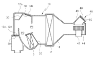
도 1은 세미 센터 타입 차량 공조장치를 개략적으로 나타낸 단면도로서, 상기한 차량용 공조장치는 공조케이스(10)를 구비한다. 공조케이스(10)에는 입구단에 송풍장치(40)가 설치된다.1 is a cross-sectional view schematically showing a semi-center type vehicle air conditioner, wherein the vehicle air conditioner includes an
상기 송풍장치(40)는, 송풍모터(42)에 의하여 구동되는 송풍팬(44)을 구비한다. 또한, 상기 송풍팬(44)의 상부에는, 실내외 공기를 유입하기 위한 내기유입구(46) 및 외기유입구(48)가 형성되어 있다. 상기한 유입구들(46)(48)은, 그 사이에 설치된 내외기전환도어(50)의 회동에 따라 개폐 조절된다. The
상기한 송풍장치(40)는, 송풍모터(42)의 구동으로 송풍팬(44)이 회전하게 된다. 상기 송풍팬(44)은, 내외기전환도어(50)의 회동으로 개방되는 내기유입구(46) 또는 외기유입구(48)측의 공기를 유입하게 된다.In the
상기한 외기유입구(48) 또는 내기유입구(46)를 거쳐 유입된 내/외기는, 송풍팬(44)에 의하여 공조케이스(10)의 내부통로(52)로 송풍된다.The inside / outside air introduced through the
그리고 상기한 송풍장치(40)와 내부통로(52)로 연결되는 공조케이스(10)는, 도 2에 도시한 바와 같이, 입구측에 공기유입구(54)가 형성되고 출구측에는 디프로스트 벤트(Defrost Vent; 12a), 페이스 벤트(Face Vent; 12b), 플로어 벤트(Floor Vent; 12c,12d)가 형성된다.And the
상기 공조케이스(10)의 내부에는 증발기(2) 및 히터코어(3)가 설치된다. 또한, 상기 증발기(2)와 히터코어(3)의 사이에는 히터코어(3)를 바이패스하는 냉풍통로(P1)와 히터코어(3)를 통과하는 온풍통로(P2)의 개도를 조절하여 온도를 조절하는 온도조절도어(20)가 설치되어 있다.An
그리고, 상기 각 벤트(12a~12d)측에는, 공조모드에 따라 각 벤트(12a~12d)의 개도를 조절하는 모드도어(30)가 설치되어 있다.And the said
한편, 고급 승용차 및 레져(Leisure)용 차량에는, 도 3에 도시한 바와 같이, 음식물이나 음료 등을 냉장 보관하기 위한 차량용 쿨박스(60)가 조수석 앞 글로브 박스(도시 생략)에 설치되어 있다.On the other hand, as shown in Fig. 3, in a high-end passenger car and a leisure vehicle, a vehicle
상기한 차량용 쿨박스(60)는, 냉/온장시킨 보관 내용물을 차량내에서 편리하게 섭취할 수 있도록 한다.The vehicle
이러한 내용물을 냉/온장시키는 쿨박스(60)는, 플렉시블한 호스(70)로 공조케이스(10)의 측면과 연결된다. 이에 따라, 쿨박스(60)에는 증발기(2)로부터 열 교환이 된 공기가 공급된다.The
그리고, 상기 플렉시블한 호스(70)가 설치되는 공조케이스(10)의 일측면에는, 차량 실내의 온도를 측정하면서 습도도 부가적으로 측정하기 위하여 차량 실내공기를 강제 흡입하는 어스피레이터(80)가 설치되어 있다.On one side of the
이러한 어스피레이터(80)는 공조케이스(10)의 내부와 연통하도록 설치되고, 차량 실내의 공기를 흡입하는 흡입파이프(82)가 일측에 연결 설치된다. The
상기한 흡입파이프(82)의 입구는 차량 실내와 연통하고 출구는 어스피레이터(80)의 내부까지 연장되도록 형성된다.The inlet of the
이에 따라, 공조케이스(10)로부터 인출된 공기는 어스피레이터(80)의 내부를 통과할 때, 흡입파이프(82)를 통해 차량 실내의 공기를 강제 흡입하게 된다.Accordingly, when the air drawn from the
흡입파이프(82)를 통해 흡입되는 차량의 실내 공기는, 흡입파이프(82) 일측 끝단에 설치된 센서(도시 생략)를 통과하게 된다. 이러한 센서는, 차량 실내의 온도를 측정하면서 부가적으로 습도도 측정한다. The indoor air of the vehicle sucked through the
상기한 바와 같이, 쿨박스 사용에 따른 공조케이스(10)의 측면은, 플렉시블한 호스(70)와 어스피레이터(80)가 별도로 설치됨으로써, 부품수가 증가하고 공조케이스의 측면 공간이 복잡하고 협소해짐에 따라 조립이 불편하고 조립공수가 증가하게 되는 문제점이 있다.As described above, the side surface of the
본 발명은 상기한 종래기술의 문제점을 해소하기 위하여 제안된 것으로서, 본 발명의 목적은, 어스피레이터를 쿨박스에 직접 연결함으로써, 공조케이스 내부의 공기를 쿨박스에 용이하게 공급할 수 있도록 하는데 있다.The present invention has been proposed in order to solve the above problems of the prior art, an object of the present invention, by connecting the aspirator directly to the cool box, it is possible to easily supply the air in the air conditioning case to the cool box.
본 발명의 다른 목적은, 쿨박스에 대한 냉기 공급을 어스피레이터 하나만 설치하여 공급함으로써, 조립 공수의 감소로 작업성이 향상되도록 하는데 있다.Another object of the present invention is to provide a cold air supply to the cool box by installing only one aspirator, thereby improving workability by reducing the number of assembly labor.
본 발명의 또 다른 목적은, 쿨박스에 대한 냉기 공급에 사용되는 플렉시블한 호스를 삭제하여 어스피레이터로 일원화하고, 금형 단순화를 통해 원가를 절감할 수 있도록 하는데 있다.Still another object of the present invention is to eliminate the flexible hose used for cold air supply to the cool box to unify the aspirator, and to reduce the cost by simplifying the mold.
본 발명의 또 다른 목적은, 어스피레이터의 일측에 개폐부재를 설치함으로써, 쿨박스 사용 및 어스피레이터의 작동을 용이하게 선택할 수 있도록 하는데 있다. Still another object of the present invention is to provide an opening and closing member on one side of the aspirator so that the use of the cool box and the operation of the aspirator can be easily selected.
이러한 목적을 달성하기 위한 본 발명은, 내부에 증발기 및 히터코어가 설치된 공조케이스와, 상기 공조케이스의 외측면에 연통되게 결합됨과 아울러 공조케이스 내부로부터 인출되는 공기의 부압에 의해 차량 실내의 공기를 흡입하여 센서를 통과하도록 하는 어스피레이터를 포함하여 이루어진 차량용 공조장치에 있어서, 상기 어스피레이터는, 차실내 공기를 흡입하는 흡입파이프와, 상기 흡입파이프 및 공조케이스 일측면에 연통되게 설치되어, 차실내 또는 공조케이스 내부로부터 흡입한 공기를 실내로 배출하는 배출구 또는 쿨박스에 배출하는 공급구로 공급할 수 있도록 분기 형성되는 연결관부재와, 상기 연결관부재의 배출구 및 공급구의 분기부에는 배출구 또는 공급구를 개폐할 수 있도록 설치된 개폐부재를 포함하는 것을 특징으로 한다.The present invention for achieving this purpose, the air-conditioning case is installed inside the evaporator and the heater core, and coupled to the outer surface of the air conditioning case and coupled to the air inside the vehicle by the negative pressure of the air drawn from the inside of the air conditioning case In the vehicle air conditioner comprising an aspirator to inhale and pass through the sensor, the aspirator is installed in communication with the suction pipe for sucking the air in the cabin, the suction pipe and one side of the air conditioning case, A connecting pipe member which is branched to be supplied to a supply port for discharging the air sucked from inside the cabin or inside the air conditioner to a discharge box or a cool box, and a discharge port or a supply port at a branch of the discharge pipe and the supply port of the connection pipe member. It characterized in that it comprises an opening and closing member installed to open and close the.
상기한 개폐부재는, 연결관부재의 배출구 및 공급구사이에 설치되는 개폐도어와, 상기 개폐도어를 조절하여 배출구 및 공급구사이에서 작동할 수 있도록 연결관부재에 설치되는 액츄에이터와, 상기 액츄에이터를 작동시킬 수 있도록 전원을 인가하는 조작부재를 포함하는 것을 특징으로 한다.The opening and closing member, the opening and closing door is installed between the outlet and the supply port of the connection pipe member, the actuator installed in the connection pipe member to operate between the outlet and the supply port by adjusting the opening and closing door, and to operate the actuator It characterized in that it comprises a control member for applying power to be able.
상기한 조작부재는, 쿨박스 및 어스피레이터의 사용을 용이하게 선택할 수 있도록 쿨박스측에 설치되는 것을 특징으로 한다.The operation member is characterized in that installed on the cool box side so that the use of the cool box and the aspirator can be easily selected.
상기한 쿨박스에 공기를 공급하지 않을 때 공급구를 폐쇄하고 배출구를 개방하도록 개폐부재를 제어하고, 쿨박스에 공기를 공급할 때 공급구를 개방하고 배출구를 폐쇄하도록 개폐부재를 제어하는 제어수단을 구비하는 것을 특징으로 한다.And a control means for controlling the opening and closing member to close the supply port and open the outlet when the air is not supplied to the cool box, and to control the opening and closing member to open the supply port and close the outlet when supplying air to the cool box. It is characterized by.
본 발명에 의하면, 공조케이스에서 인출되는 공기를 쿨박스에 공급할 수 있도록 공조케이스의 측면과 쿨박스를 어스피레이터의 연결부재로 직접 연결함으로써, 협소한 공간에서 용이하게 설치할 수 있는 효과가 있다.According to the present invention, by directly connecting the side of the air conditioning case and the cool box to the connection member of the aspirator so that the air drawn from the air conditioning case can be supplied to the cool box, there is an effect that can be easily installed in a narrow space.
또한, 쿨박스에 대한 냉기 공급을 어스피레이터 하나만을 이용함으로써, 조립 공수가 줄어 조립성이 향상되고 금형의 단순화로 원가를 절감할 수 있는 효과가 있다.In addition, by using only one aspirator to supply the cool air to the cool box, the assembly labor is reduced, the assembly performance is improved, and the cost can be reduced by simplifying the mold.
또한, 상기 어스피레이터를 통해 버려지는 냉기를 쿨박스의 냉매로 활용함으로써, 내용물의 냉장 효율을 향상시킬 수 있는 효과가 있다.In addition, by utilizing the cold air discarded through the aspirator as the refrigerant of the cool box, there is an effect that can improve the refrigeration efficiency of the contents.
또한, 공조케이스 내부로터 온풍을 쿨박스에 공급하면, 온장고로도 사용할 수 있는 효과가 있다. In addition, by supplying the warm air inside the air conditioning case to the cool box, there is an effect that can be used as a warmer.
도 1은, 종래의 공조장치를 나타내는 구성도.
도 2는 종래의 세미 센터 타입 공조장치의 일예를 나타내는 단면도.
도 3은 종래의 공조케이스와 쿨박스를 플렉시블한 호스로 연결한 경우를 나타내는 사시도.
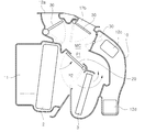
도 4는 본 발명에 따른 차량용 공조장치를 나타내는 사시도,
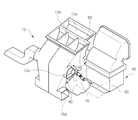
도 5는 본 발명에 따른 차량용 공조장치에서 어스피레이터와 연결부재를 나타내는 결합 사시도,
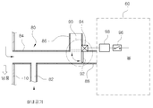
도 6은 본 발명에 따른 차량용 공조장치에서 어스피레이터와 연결부재를 나타내는 분해 사시도이다.1 is a block diagram showing a conventional air conditioning apparatus.
2 is a cross-sectional view showing an example of a conventional semi-center type air conditioner.
Figure 3 is a perspective view showing a case of connecting the conventional air conditioning case and the cool box with a flexible hose.
4 is a perspective view showing the vehicle air conditioner according to the present invention;
5 is a perspective view of the coupling showing the aspirator and the connecting member in the vehicle air conditioner according to the present invention;
6 is an exploded perspective view illustrating the aspirator and the connecting member in the vehicle air conditioner according to the present invention.
이하, 본 발명의 바람직한 일 실시예를 첨부한 도면에 의하여 더욱 상세하게 설명한다(종래기술과 동일한 구성요소에 대해서는 동일한 부호를 부여하여 설명한다).Hereinafter, a preferred embodiment of the present invention will be described in more detail with reference to the accompanying drawings (the same components as in the prior art will be described with the same reference numerals).
차량용 공조장치는, 도 1 내지 도 3에 도시한 바와 같이, 내부에 증발기(2) 및 히터코어(3)가 설치된 공조케이스(10)와, 상기 공조케이스(10)의 외측면에 연통되게 결합됨과 아울러 공조케이스(10) 내부로부터 인출되는 공기의 부압에 의해 차량 실내의 공기를 흡입하면서 공조케이스(10) 내부 공기를 쿨박스(60)에 공급하는 어스피레이터(80)를 포함한다. As shown in FIGS. 1 to 3, the vehicle air conditioner is coupled to be in communication with an
다음으로, 본 발명에 따른 차량용 공조장치의 특징부를 도 4 내지 도 6을 참조하여 상세하게 설명한다. Next, the features of the vehicle air conditioner according to the present invention will be described in detail with reference to FIGS. 4 to 6.
상기한 어스피레이터(80)는, 차실내 공기를 흡입하는 흡입파이프(82)를 구비한다. 상기한 흡입파이프(82)에는, 차실내의 공기를 흡입할 때 공기의 온도를 감지할 수 있도록 센서(도시 생략)가 설치되어 있다. 상기한 센서는, 차량 실내의 온도를 주로 측정하고 부가적으로 습도도 측정한다. The
상기 흡입파이프(82)를 통해 흡입되는 차량의 실내 공기는, 양이 매우 적기 때문에 연결관부재(84)를 통해 쿨박스(60)에 공급되더라도 냉장 기능에 별다른 영향을 미치지 않는다.Since the indoor air of the vehicle sucked through the
또한, 어스피레이터(80)는, 상기 흡입파이프(82)의 타측에 차실내 공기나 공조케이스(10) 내부 공기를 차실내로 배출하는 배출구(86)와 쿨박스(60)에 배출하는 공급구(88)가 분기 형성되는 연결관부재(84)를 구비한다.In addition, the
상기한 배출구(86) 및 공급구(88)는, 개폐조절이 용이하도록 상호 근접하게 형성하는 것이 바람직하다. The
상기 연결관부재(84)는, 공조케이스(10) 내부에서 열교환된 공기를 쿨박스(60)에 공급할 수 있도록 직접 연결되기 때문에 협소한 공간에 용이하게 설치할 수 있다. The connecting
상기한 연결관부재(84)를 형성한 어스피레이터(80)는, 쿨박스(60)에 냉기 공급시 하나만 설치되기 때문에 조립공수가 절감되어 조립성을 향상시킨다.Since the
상기 어스피레이터(80)는, 상기 증발기(2)의 하류측에 설치되는 경우 증발기(2)를 통과한 냉풍 중 일부를 쿨박스(60)에 공급할 수 있으므로 냉장효율을 향상시킨다.When the
또한, 상기 어스피레이터(80)는, 히터코어(3)의 하류측에 연결할 경우 히터코어(3)를 통과한 온풍 중 일부를 쿨박스(60)에 공급하여 온장 기능도 수행할 수 있다.In addition, when the
상기 어스피레이터(80)는 앞서 설명한 위치 외에도 공조케이스(40) 외측면에 위치하도록 다양하게 설치할 수 있다.The
또한, 상기 어스피레이터(80)에는 상기 연결관부재(84)의 배출구(86) 및 공급구(88)를 개폐하기 위한 사이에 개폐부재(90)가 설치된다.In addition, the
상기한 개폐부재(90)는, 연결관부재(84)의 배출구(86) 및 공급구(88)를 개폐할 수 있도록 하는 개폐도어(92)를 구비한다. The opening and closing
그리고, 상기 개폐부재(90)는, 상기 개폐도어(92)를 배출구(86) 및 공급구(88)사이에서 작동시킬 수 있도록 연결관부재(84)에 설치되는 액츄에이터(94)를 구비한다.The opening / closing
또한, 상기 개폐부재(90)는, 액츄에이터(94)를 작동시킬 수 있도록 전원을 인가하는 조작부재(96)를 구비한다.In addition, the opening and closing
또한, 개폐부재(90)는, 조작부재(96)의 신호시 제어수단(98)에 의하여 제어된다. 즉, 상기 쿨박스(60)에 공기를 공급하지 않을 때 공급구(88)를 폐쇄하고 배출구(86)를 개방하도록 개폐부재(90)를 제어하고, 쿨박스(60)에 공기를 공급할 때 공급구(88)를 개방하고 배출구(86)를 폐쇄하도록 개폐부재(90)를 자동으로 제어할 수 있다.In addition, the opening and closing
상기한 조작부재(96)는, 쿨박스(60) 및 어스피레이터(80)의 사용 유무에 따라 배출구(86) 및 공급구(88)의 개폐를 선택할 수 있도록 쿨박스(60)측에 설치된다.The
이에 따라, 조작부재(96)가 조작되면, 공조케이스(10)로부터 인출되는 공기는 어스피레이터(80)의 연결관부재(84)를 통해 쿨박스(60)에 냉풍이 공급되도록 한다.Accordingly, when the
이러한 개폐부재(90)는, 모터 및 액츄에이터(80) 등 별도의 작동수단을 구비하지 않고, 탑승자가 직접 개폐도어(92)를 슬라이드 또는 회동시켜 배출구(86) 및 공급구(88)를 수동으로도 개폐할 수 있다.The opening and closing
이하, 상기한 바와 같이 이루어지는 본 발명의 작용을 어스피레이터(80)가 증발기(2)의 하류측에 설치된 경우를 예로서 설명한다.Hereinafter, the case where the
공조장치를 냉방모드로 가동시키면, 상기 증발기(2)를 통과하면서 열교환된 냉풍 중 대부분은 상기 온도조절도어(20)에 의해 상기 히터코어(3)를 바이패스 하여 이동한다.When the air conditioner is operated in the cooling mode, most of the cold air heat-exchanged while passing through the
상기 히터코어(3)를 바이패스한 냉풍은, 공조모드에 따라 선택된 모드도어(30)에 의하여 개방된 각 벤트(12)를 통해 공급된 차실내를 냉방하게 된다. The cold air bypassing the
그리고, 쿨박스(60)를 사용하기 위하여 조작부재(96)를 조작하면, 액츄에이터(94)에 의하여 개폐도어(92)는 배출구(86)를 차단하게 된다.In addition, when the
이에 따라, 상기 증발기(2)를 통과하면서 열교환된 냉풍 중 일부는, 어스피레이터(80)의 연결관부재(84)를 통해 인출된다.Accordingly, some of the cold air heat exchanged while passing through the
상기한 어스피레이터(80)를 통해 인출된 냉풍은, 공기흡입작용을 통해 차량 실내의 공기를 흡입파이프(82)를 통해 흡입한다.The cold air drawn out through the
이때, 상기 흡입파이프(82)의 단부에 설치되는 센서(도시 생략)는 차량실내의 공기를 통해 습도 및 온도를 감지한 후 제어부에 정보를 제공한다.In this case, a sensor (not shown) installed at the end of the
그리고, 상기 어스피레이터(80)의 연결관부재(84)를 통해 인출된 냉풍은, 연결관부재(84)를 통해 개폐도어(92)에 의하여 개방된 공급구(880)를 통해 쿨박스(60)에 공급된다.The cold air drawn out through the connecting
상기한 쿨박스(60)에 공급된 냉풍은 쿨박스(60)에 저장된 내용물을 냉장하게 된다.The cold air supplied to the
그리고, 쿨박스(60)를 사용하지 않으면, 쿨박스(60)의 전면에 설치된 조작부재(96)를 오프(Off) 조작한다.If the
상기한 조작부재(96)가 오프되면, 개폐도어(92)는 어스피레이터(80)를 작동시킬 수 있도록 공급구(88)는 닫고 배출구(86)는 개방하게 된다.When the
이에 따라, 어스피레이터(80)를 통해 인출된 공기는, 연결관부재(84) 및 배출구(86)를 통해 배출된다.Accordingly, the air drawn out through the
본 발명은 쿨박스를 예로 들어 설명하였으나, 온장고로도 사용할 수 있다. 즉, 공조케이스(10) 내부로부터 온풍을 인출하여 공급하면, 쿨박스(60)는 온장고 기능을 하게 되고, 공조케이스(10) 내부로부터 냉풍을 인출하여 공급하면 온장고는 쿨박스 기능을 하게 된다.Although the present invention has been described taking a cool box as an example, it may be used as a warmer. That is, if the hot air is drawn out from the
본 발명은 공조케이스의 내부 공기를 인출하여 쿨박스에 공급하는 어스피레이터의 일측에 배출구 및 공급구를 개폐하는 개폐부재를 설치함으로써, 쿨박스 및 어스피레이터를 선택하여 사용할 수 있도록 한 것으로, 차량용 공조장치 산업분야에 널리 이용될 수 있다.The present invention is to install the opening and closing member for opening and closing the outlet and supply port on one side of the aspirator to draw the internal air of the air conditioning case to supply to the cool box, to select and use the cool box and the aspirator, It can be widely used in the device industry.
60: 쿨박스(Cool Box) 80: 어스피레이터(Aspirator)
84: 연결관부재 86: 배출구
88: 공급구 90: 개폐부재
92: 개폐도어 94: 액츄에이터(Actuator)
96: 조작부재60: Cool Box 80: Aspirator
84: connecting member 86: outlet
88: supply port 90: opening and closing member
92: opening and closing door 94: actuator
96: operation member
Claims (4)
상기 어스피레이터(80)는,
차실내 공기를 흡입하는 흡입파이프(82)와,
상기 흡입파이프(82) 및 공조케이스(10) 일측면에 연통되게 설치되어, 차실내 또는 공조케이스(10) 내부로부터 흡입한 공기를 실내로 배출하는 배출구(86) 또는 쿨박스(60)에 배출하는 공급구(88)로 공급할 수 있도록 분기 형성되는 연결관부재(84)와,
상기 연결관부재(84)의 배출구(86) 및 공급구(88)의 분기부에는 배출구(86) 또는 공급구(88)를 개폐할 수 있도록 설치된 개폐부재(90)를 포함하는 것을 특징으로 하는 차량용 공조장치.The air conditioner case 10 having the evaporator 2 and the heater core 3 installed therein is coupled to the outer surface of the air conditioner case 10, and the negative pressure of air drawn out from the inside of the air conditioner case 10. In the vehicle air conditioner comprising an aspirator 80 to suck the air in the vehicle interior and pass through the sensor,
The aspirator 80,
A suction pipe 82 for sucking air in the vehicle,
It is installed in communication with one side of the suction pipe 82 and the air conditioning case 10, and discharged to the discharge port 86 or the cool box 60 for discharging the air sucked from the interior or the air conditioning case 10 to the interior A connecting pipe member 84 branched to be supplied to the supply port 88,
Branches of the outlet 86 and the supply port 88 of the connecting pipe member 84, characterized in that it comprises an opening and closing member 90 is installed to open and close the outlet 86 or the supply port 88 Vehicle air conditioning system.
상기 개폐부재(90)는,
연결관부재(84)의 배출구(86) 및 공급구(88)사이에 설치되는 개폐도어(92)와, 상기 개폐도어(92)를 조절하여 배출구(86) 및 공급구(88)사이에서 작동할 수 있도록 연결관부재(84)에 설치되는 액츄에이터(94)와, 상기 액츄에이터(94)를 작동시킬 수 있도록 전원을 인가하는 조작부재(96)를 포함하는 것을 특징으로 하는 차량용 공조장치.The method of claim 1,
The opening and closing member 90,
Opening and closing door 92 is installed between the discharge port 86 and the supply port 88 of the connecting pipe member 84, and operates between the discharge port 86 and the supply port 88 by adjusting the opening and closing door 92 An actuator (94) installed in the connecting pipe member (84) so as to be able to operate, and the vehicle air conditioner comprising a control member (96) for applying power to operate the actuator (94).
상기 조작부재(96)는,
쿨박스(60) 및 어스피레이터(80)의 사용을 용이하게 선택할 수 있도록 쿨박스(60)측에 설치되는 것을 특징으로 하는 차량용 공조장치.The method of claim 2,
The operation member 96,
Vehicle air conditioner, characterized in that installed on the cool box 60 side to facilitate the use of the cool box 60 and the aspirator 80.
상기 쿨박스(60)에 공기를 공급하지 않을 때 공급구(88)를 폐쇄하고 배출구(86)를 개방하도록 개폐부재(90)를 제어하고, 쿨박스(60)에 공기를 공급할 때 공급구(88)를 개방하고 배출구(86)를 폐쇄하도록 개폐부재(90)를 제어하는 제어수단(98)을 구비하는 것을 특징으로 하는 차량용 공조장치.The method of claim 1,
The opening and closing member 90 is controlled to close the supply port 88 and open the discharge port 86 when the air is not supplied to the cool box 60, and the supply port 88 when supplying air to the cool box 60. Vehicle control apparatus comprising a control means for controlling the opening and closing member (90) to open and close the outlet (86).
Priority Applications (1)
| Application Number | Priority Date | Filing Date | Title |
|---|---|---|---|
| KR1020100124338A KR20120063243A (en) | 2010-12-07 | 2010-12-07 | Air conditioning apparatus for automotive vehicles |
Applications Claiming Priority (1)
| Application Number | Priority Date | Filing Date | Title |
|---|---|---|---|
| KR1020100124338A KR20120063243A (en) | 2010-12-07 | 2010-12-07 | Air conditioning apparatus for automotive vehicles |
Publications (1)
| Publication Number | Publication Date |
|---|---|
| KR20120063243A true KR20120063243A (en) | 2012-06-15 |
Family
ID=46683799
Family Applications (1)
| Application Number | Title | Priority Date | Filing Date |
|---|---|---|---|
| KR1020100124338A Ceased KR20120063243A (en) | 2010-12-07 | 2010-12-07 | Air conditioning apparatus for automotive vehicles |
Country Status (1)
| Country | Link |
|---|---|
| KR (1) | KR20120063243A (en) |
-
2010
- 2010-12-07 KR KR1020100124338A patent/KR20120063243A/en not_active Ceased
Similar Documents
| Publication | Publication Date | Title |
|---|---|---|
| US20050087332A1 (en) | Air-conditioning system for motor vehicle | |
| WO2000061395A1 (en) | Air conditioner for vehicle | |
| US20080016892A1 (en) | Air conditioner for vehicles | |
| JP3794132B2 (en) | Air conditioner for vehicles | |
| KR101748202B1 (en) | Air conditioner for vehicles | |
| JP3814987B2 (en) | Air conditioner for vehicles | |
| KR20120063243A (en) | Air conditioning apparatus for automotive vehicles | |
| JP2003285620A (en) | Inside/outside air switching device of air conditioner for vehicle | |
| JP4265046B2 (en) | Air conditioner for vehicles | |
| KR20100065896A (en) | Air conditioner for vehicles | |
| KR101529218B1 (en) | Vehicle air conditioning system | |
| KR101703203B1 (en) | Air conditioning system for electric automotive vehicles | |
| KR20130048485A (en) | Air conditioner for vehicles | |
| JP3680443B2 (en) | Air conditioning system for rear seats of vehicles | |
| KR20100134437A (en) | Car air conditioner | |
| JP3494021B2 (en) | Vehicle air conditioner | |
| KR101172695B1 (en) | Air conditioner for vehicles | |
| KR101737916B1 (en) | Air conditioner for vehicle | |
| KR101679674B1 (en) | Air conditioning apparatus for automotive vehicles | |
| JP3189474B2 (en) | Vehicle air conditioner | |
| JP2000355208A (en) | Air conditioning device for vehicle | |
| JPH07205639A (en) | Air conditioner for vehicle | |
| KR20100020797A (en) | Air conditioner for vehicles | |
| KR20090129591A (en) | Car air conditioner | |
| KR101558002B1 (en) | Air conditioner and method for controlling ventilation of the same |
Legal Events
| Date | Code | Title | Description |
|---|---|---|---|
| PA0109 | Patent application |
St.27 status event code: A-0-1-A10-A12-nap-PA0109 |
|
| PG1501 | Laying open of application |
St.27 status event code: A-1-1-Q10-Q12-nap-PG1501 |
|
| R18-X000 | Changes to party contact information recorded |
St.27 status event code: A-3-3-R10-R18-oth-X000 |
|
| PN2301 | Change of applicant |
St.27 status event code: A-3-3-R10-R13-asn-PN2301 St.27 status event code: A-3-3-R10-R11-asn-PN2301 |
|
| PN2301 | Change of applicant |
St.27 status event code: A-3-3-R10-R13-asn-PN2301 St.27 status event code: A-3-3-R10-R11-asn-PN2301 |
|
| A201 | Request for examination | ||
| PA0201 | Request for examination |
St.27 status event code: A-1-2-D10-D11-exm-PA0201 |
|
| P22-X000 | Classification modified |
St.27 status event code: A-2-2-P10-P22-nap-X000 |
|
| E902 | Notification of reason for refusal | ||
| PE0902 | Notice of grounds for rejection |
St.27 status event code: A-1-2-D10-D21-exm-PE0902 |
|
| E13-X000 | Pre-grant limitation requested |
St.27 status event code: A-2-3-E10-E13-lim-X000 |
|
| P11-X000 | Amendment of application requested |
St.27 status event code: A-2-2-P10-P11-nap-X000 |
|
| P13-X000 | Application amended |
St.27 status event code: A-2-2-P10-P13-nap-X000 |
|
| E601 | Decision to refuse application | ||
| PE0601 | Decision on rejection of patent |
St.27 status event code: N-2-6-B10-B15-exm-PE0601 |
|
| P22-X000 | Classification modified |
St.27 status event code: A-2-2-P10-P22-nap-X000 |
|
| PN2301 | Change of applicant |
St.27 status event code: A-3-3-R10-R13-asn-PN2301 St.27 status event code: A-3-3-R10-R11-asn-PN2301 |
|
| R11 | Change to the name of applicant or owner or transfer of ownership requested |
Free format text: ST27 STATUS EVENT CODE: A-3-3-R10-R11-ASN-PN2301 (AS PROVIDED BY THE NATIONAL OFFICE) |
|
| R13 | Change to the name of applicant or owner recorded |
Free format text: ST27 STATUS EVENT CODE: A-3-3-R10-R13-ASN-PN2301 (AS PROVIDED BY THE NATIONAL OFFICE) |