KR20120040239A - Mems jetting structure for dense packing - Google Patents
Mems jetting structure for dense packing Download PDFInfo
- Publication number
- KR20120040239A KR20120040239A KR1020127003663A KR20127003663A KR20120040239A KR 20120040239 A KR20120040239 A KR 20120040239A KR 1020127003663 A KR1020127003663 A KR 1020127003663A KR 20127003663 A KR20127003663 A KR 20127003663A KR 20120040239 A KR20120040239 A KR 20120040239A
- Authority
- KR
- South Korea
- Prior art keywords
- fluid
- injector
- pumping chamber
- module
- fluid injector
- Prior art date
Links
Images


Classifications
-
- B—PERFORMING OPERATIONS; TRANSPORTING
- B41—PRINTING; LINING MACHINES; TYPEWRITERS; STAMPS
- B41J—TYPEWRITERS; SELECTIVE PRINTING MECHANISMS, i.e. MECHANISMS PRINTING OTHERWISE THAN FROM A FORME; CORRECTION OF TYPOGRAPHICAL ERRORS
- B41J2/00—Typewriters or selective printing mechanisms characterised by the printing or marking process for which they are designed
- B41J2/005—Typewriters or selective printing mechanisms characterised by the printing or marking process for which they are designed characterised by bringing liquid or particles selectively into contact with a printing material
- B41J2/01—Ink jet
- B41J2/135—Nozzles
- B41J2/14—Structure thereof only for on-demand ink jet heads
- B41J2/1433—Structure of nozzle plates
-
- B—PERFORMING OPERATIONS; TRANSPORTING
- B05—SPRAYING OR ATOMISING IN GENERAL; APPLYING FLUENT MATERIALS TO SURFACES, IN GENERAL
- B05B—SPRAYING APPARATUS; ATOMISING APPARATUS; NOZZLES
- B05B12/00—Arrangements for controlling delivery; Arrangements for controlling the spray area
- B05B12/02—Arrangements for controlling delivery; Arrangements for controlling the spray area for controlling time, or sequence, of delivery
- B05B12/04—Arrangements for controlling delivery; Arrangements for controlling the spray area for controlling time, or sequence, of delivery for sequential operation or multiple outlets
-
- B—PERFORMING OPERATIONS; TRANSPORTING
- B41—PRINTING; LINING MACHINES; TYPEWRITERS; STAMPS
- B41J—TYPEWRITERS; SELECTIVE PRINTING MECHANISMS, i.e. MECHANISMS PRINTING OTHERWISE THAN FROM A FORME; CORRECTION OF TYPOGRAPHICAL ERRORS
- B41J2/00—Typewriters or selective printing mechanisms characterised by the printing or marking process for which they are designed
- B41J2/005—Typewriters or selective printing mechanisms characterised by the printing or marking process for which they are designed characterised by bringing liquid or particles selectively into contact with a printing material
- B41J2/01—Ink jet
- B41J2/135—Nozzles
- B41J2/14—Structure thereof only for on-demand ink jet heads
- B41J2/14201—Structure of print heads with piezoelectric elements
- B41J2/14233—Structure of print heads with piezoelectric elements of film type, deformed by bending and disposed on a diaphragm
-
- B—PERFORMING OPERATIONS; TRANSPORTING
- B41—PRINTING; LINING MACHINES; TYPEWRITERS; STAMPS
- B41J—TYPEWRITERS; SELECTIVE PRINTING MECHANISMS, i.e. MECHANISMS PRINTING OTHERWISE THAN FROM A FORME; CORRECTION OF TYPOGRAPHICAL ERRORS
- B41J2/00—Typewriters or selective printing mechanisms characterised by the printing or marking process for which they are designed
- B41J2/005—Typewriters or selective printing mechanisms characterised by the printing or marking process for which they are designed characterised by bringing liquid or particles selectively into contact with a printing material
- B41J2/01—Ink jet
- B41J2/135—Nozzles
- B41J2/145—Arrangement thereof
-
- B—PERFORMING OPERATIONS; TRANSPORTING
- B41—PRINTING; LINING MACHINES; TYPEWRITERS; STAMPS
- B41J—TYPEWRITERS; SELECTIVE PRINTING MECHANISMS, i.e. MECHANISMS PRINTING OTHERWISE THAN FROM A FORME; CORRECTION OF TYPOGRAPHICAL ERRORS
- B41J2/00—Typewriters or selective printing mechanisms characterised by the printing or marking process for which they are designed
- B41J2/005—Typewriters or selective printing mechanisms characterised by the printing or marking process for which they are designed characterised by bringing liquid or particles selectively into contact with a printing material
- B41J2/01—Ink jet
- B41J2/17—Ink jet characterised by ink handling
- B41J2/175—Ink supply systems ; Circuit parts therefor
-
- B—PERFORMING OPERATIONS; TRANSPORTING
- B41—PRINTING; LINING MACHINES; TYPEWRITERS; STAMPS
- B41J—TYPEWRITERS; SELECTIVE PRINTING MECHANISMS, i.e. MECHANISMS PRINTING OTHERWISE THAN FROM A FORME; CORRECTION OF TYPOGRAPHICAL ERRORS
- B41J2/00—Typewriters or selective printing mechanisms characterised by the printing or marking process for which they are designed
- B41J2/005—Typewriters or selective printing mechanisms characterised by the printing or marking process for which they are designed characterised by bringing liquid or particles selectively into contact with a printing material
- B41J2/01—Ink jet
- B41J2/135—Nozzles
- B41J2/14—Structure thereof only for on-demand ink jet heads
- B41J2/14016—Structure of bubble jet print heads
- B41J2/14032—Structure of the pressure chamber
- B41J2/1404—Geometrical characteristics
-
- B—PERFORMING OPERATIONS; TRANSPORTING
- B41—PRINTING; LINING MACHINES; TYPEWRITERS; STAMPS
- B41J—TYPEWRITERS; SELECTIVE PRINTING MECHANISMS, i.e. MECHANISMS PRINTING OTHERWISE THAN FROM A FORME; CORRECTION OF TYPOGRAPHICAL ERRORS
- B41J2/00—Typewriters or selective printing mechanisms characterised by the printing or marking process for which they are designed
- B41J2/005—Typewriters or selective printing mechanisms characterised by the printing or marking process for which they are designed characterised by bringing liquid or particles selectively into contact with a printing material
- B41J2/01—Ink jet
- B41J2/135—Nozzles
- B41J2/14—Structure thereof only for on-demand ink jet heads
- B41J2/14016—Structure of bubble jet print heads
- B41J2/14032—Structure of the pressure chamber
- B41J2/14056—Plural heating elements per ink chamber
-
- B—PERFORMING OPERATIONS; TRANSPORTING
- B41—PRINTING; LINING MACHINES; TYPEWRITERS; STAMPS
- B41J—TYPEWRITERS; SELECTIVE PRINTING MECHANISMS, i.e. MECHANISMS PRINTING OTHERWISE THAN FROM A FORME; CORRECTION OF TYPOGRAPHICAL ERRORS
- B41J2/00—Typewriters or selective printing mechanisms characterised by the printing or marking process for which they are designed
- B41J2/005—Typewriters or selective printing mechanisms characterised by the printing or marking process for which they are designed characterised by bringing liquid or particles selectively into contact with a printing material
- B41J2/01—Ink jet
- B41J2/135—Nozzles
- B41J2/14—Structure thereof only for on-demand ink jet heads
- B41J2/14201—Structure of print heads with piezoelectric elements
- B41J2/14233—Structure of print heads with piezoelectric elements of film type, deformed by bending and disposed on a diaphragm
- B41J2002/14241—Structure of print heads with piezoelectric elements of film type, deformed by bending and disposed on a diaphragm having a cover around the piezoelectric thin film element
-
- B—PERFORMING OPERATIONS; TRANSPORTING
- B41—PRINTING; LINING MACHINES; TYPEWRITERS; STAMPS
- B41J—TYPEWRITERS; SELECTIVE PRINTING MECHANISMS, i.e. MECHANISMS PRINTING OTHERWISE THAN FROM A FORME; CORRECTION OF TYPOGRAPHICAL ERRORS
- B41J2/00—Typewriters or selective printing mechanisms characterised by the printing or marking process for which they are designed
- B41J2/005—Typewriters or selective printing mechanisms characterised by the printing or marking process for which they are designed characterised by bringing liquid or particles selectively into contact with a printing material
- B41J2/01—Ink jet
- B41J2/135—Nozzles
- B41J2/14—Structure thereof only for on-demand ink jet heads
- B41J2002/14491—Electrical connection
-
- B—PERFORMING OPERATIONS; TRANSPORTING
- B41—PRINTING; LINING MACHINES; TYPEWRITERS; STAMPS
- B41J—TYPEWRITERS; SELECTIVE PRINTING MECHANISMS, i.e. MECHANISMS PRINTING OTHERWISE THAN FROM A FORME; CORRECTION OF TYPOGRAPHICAL ERRORS
- B41J2202/00—Embodiments of or processes related to ink-jet or thermal heads
- B41J2202/01—Embodiments of or processes related to ink-jet heads
- B41J2202/12—Embodiments of or processes related to ink-jet heads with ink circulating through the whole print head
Abstract
유체 분사기는 기판 및 상기 기판과 분리된 층을 포함하는 유체 분사 모듈을 포함한다. 상기 기판은 행렬로 정렬된 복수의 유체 분사 요소를 포함하고, 각각의 유체 분사 요소는 유체를 노즐로부터 분사시킬 수 있도록 구성된다. 기판과 분리된 층은 복수의 전기 연결부를 포함하고, 각각의 전기 연결부는 대응하는 유체 분사 요소에 인접한다. The fluid injector includes a fluid ejection module comprising a substrate and a layer separate from the substrate. The substrate includes a plurality of fluid ejection elements arranged in a matrix, each fluid ejection element configured to eject fluid from a nozzle. The layer separated from the substrate comprises a plurality of electrical connections, each electrical connection adjacent to a corresponding fluid ejection element.
Description
본원 발명은 일반적으로 유체 분사에 관한 것이다.
The present invention generally relates to fluid injection.
마이크로일렉트로미케니칼(미세전기기계적) 시스템, 또는 MEMS-기반형 장치(소자)가 가속도계, 자이로스코프, 압력 센서 또는 트랜스듀서, 디스플레이, 광학적 스위치, 및 유체 분사기와 같은 다양한 용도에서 사용될 수 있다. 통상적으로, 하나 또는 둘 이상의 개별적인 장치들이 하나의 다이 상에서, 예를 들어 절연 물질, 반도체 물질 또는 그 물질들의 조합으로 형성된 다이 상에서 형성된다. 다이는 포토리소그래피, 증착 및 에칭과 같은 반도체 프로세싱 기술을 이용하여 프로세싱될 수 있다.
Microelectromechanical (microelectromechanical) systems, or MEMS-based devices (devices) can be used in various applications such as accelerometers, gyroscopes, pressure sensors or transducers, displays, optical switches, and fluid injectors. Typically, one or more individual devices are formed on one die, for example on a die formed of an insulating material, a semiconductor material or a combination of materials. The die may be processed using semiconductor processing techniques such as photolithography, deposition and etching.
유체 분사 장치는 노즐로부터 매체 상으로 유체 액적(droplet)을 각각 분사할 수 있는 복수의 MEMS 장치를 가질 수 있다. 유체 액적을 분사하기 위해서 기계적인 기반의 액츄에이터를 이용하는 일부 장치들에서, 노즐들은 유체 펌핑 챔버를 포함하는 유체 경로에 유체적으로 각각 연결된다. 유체 펌핑 챔버는 액츄에이터에 의해서 작동되고, 상기 액츄에이터는 펌핑 챔버의 부피를 일시적으로 변화시키고 그리고 유체 액적의 분사를 유발한다. 매체가 다이에 대해서 상대적으로 이동될 수 있다. 특정 노즐로부터의 유체 액적의 분사는 유체 액적을 매체상의 목표된 위치에 배치하기 위해서 매체의 운동과 타이밍이 맞춰진다(timed).
The fluid ejection device may have a plurality of MEMS devices capable of ejecting fluid droplets from the nozzle onto the medium, respectively. In some devices that use a mechanically based actuator to eject a fluid droplet, the nozzles are each fluidly connected to a fluid path that includes a fluid pumping chamber. The fluid pumping chamber is operated by an actuator, which temporarily changes the volume of the pumping chamber and causes the injection of fluid droplets. The medium can be moved relative to the die. Injection of fluidic droplets from a particular nozzle is timed with the motion of the medium to place the fluidic droplets at a desired location on the medium.
제조 방법이 개선됨에 따라, 유체 분사 모듈 내의 노즐의 밀도가 증대된다. 예를 들어, 실리콘 웨이퍼 상에 제조된 MEMS-기반 장치는 적은 풋프린트(footprint)로 그리고 이전의 다이에서 보다 더 증대된 노즐 밀도로 다이 내에 형성된다. 적은 다이를 구축하는데 있어서의 하나의 장애물은 그러한 장치의 적은 풋프린트가 다이 상의 전기 콘택들이 이용할 수 있는 영역을 감소시킬 수 있다는 것이다.
As the manufacturing method improves, the density of the nozzles in the fluid injection module increases. For example, MEMS-based devices fabricated on silicon wafers are formed in a die with a small footprint and with increased nozzle densities than in previous dies. One obstacle in constructing fewer die is that the small footprint of such a device can reduce the area available to electrical contacts on the die.
일반적으로, 유체 분사 시스템은 개별적으로 제어될 수 있는 복수의 유체 분사 요소들 및 복수의 유체 분사 요소들이 작동되었을 때 유체를 분사하기 위한 복수의 노즐을 포함하는 프린트헤드 모듈을 포함하고, 상기 복수의 유체 분사 요소 및 복수의 노즐은 행과 열을 가지는 행렬(matrix)로 정렬되며, 이때 1 평방 인치 미만의 영역 내에 550 개 이상의 노즐이 있고, 그리고 노즐들은 각각의 행(row) 내에서 균일하게 이격된다.
In general, a fluid ejection system includes a printhead module comprising a plurality of individually controllable fluid ejection elements and a plurality of nozzles for ejecting fluid when the plurality of fluid ejection elements are actuated, wherein the plurality of The fluid ejection elements and the plurality of nozzles are arranged in a matrix with rows and columns, where there are more than 550 nozzles in an area of less than one square inch, and the nozzles are evenly spaced within each row. do.
이러한 그리고 다른 실시예들은 이하의 특징들 중 하나 또는 둘 이상을 선택적으로 포함할 수 있다. 1 평방 인치 미만의 영역 내에 550 내지 60,000 개의 노즐이 있을 수 있다. 1 평방 인치 미만의 영역 내에 약 1200 개의 노즐이 있을 수 있다. 행렬은 80개의 열과 18개의 행을 포함할 수 있다. 유체의 액적이 노즐로부터 매체 상으로 분배되어 한 번의 패스(pass; 통과)에서 600 dpi 보다 큰 밀도로 매체 상에 픽셀의 라인들을 형성할 수 있도록, 행렬은 구성될 수 있다. 그 밀도가 약 1200 dpi가 될 수 있다. 열은 프린트헤드 모듈의 폭을 따라서 정렬될 수 있고, 그 폭은 10 mm 미만이며, 행은 프린트헤드 모듈의 길이를 따라서 정렬될 수 있고, 그 길이는 30 mm 내지 40 mm이다. 그 폭은 약 5 mm이다. 복수의 노즐은 0.1pL 내지 100pL의 액적 크기를 가지는 유체를 분사하도록 구성될 수 있다. 프린트헤드 모듈은 실리콘을 포함할 수 있다. 유체 분사 요소는 압전 부분을 포함할 수 있다. 복수의 노즐을 포함하는 프린트헤드의 표면은 평행사변형으로서 형성될 수 있다. 노즐의 폭이 15 ㎛ 보다 클 수 있다. 행과 열 사이의 각도는 90 °미만이 될 수 있다.
These and other embodiments may optionally include one or more of the following features. There may be between 550 and 60,000 nozzles in an area of less than one square inch. There may be about 1200 nozzles in an area of less than one square inch. A matrix can contain 80 columns and 18 rows. The matrix can be configured such that droplets of fluid can be dispensed from the nozzle onto the medium to form lines of pixels on the medium at a density greater than 600 dpi in one pass. The density can be about 1200 dpi. The columns can be aligned along the width of the printhead module, the width of which is less than 10 mm, the rows can be aligned along the length of the printhead module, and the length is between 30 mm and 40 mm. Its width is about 5 mm. The plurality of nozzles may be configured to eject a fluid having a droplet size of 0.1 pL to 100 pL. The printhead module may comprise silicon. The fluid injection element may comprise a piezoelectric portion. The surface of the printhead comprising a plurality of nozzles may be formed as a parallelogram. The width of the nozzle may be greater than 15 μm. The angle between the rows and columns can be less than 90 °.
일반적으로, 하나의 양태에서, 유체 분사 모듈은 내부에 형성된 복수의 노즐을 가지는 제 1 층, 대응 노즐에 각각 유체적으로 연결된 복수의 펌핑 챔버를 가지는 제 2 층, 그리고 연관된 노즐을 통해서 펌핑 챔버로부터 유체를 분사시킬 수 있게 각각 구성되는 복수의 유체 분사 요소를 포함하고, 상기 제 1 또는 제 2 층의 하나 이상이 광 형성이 가능한(photodefinable) 필름을 포함한다.
In general, in one aspect, a fluid ejection module includes a first layer having a plurality of nozzles formed therein, a second layer having a plurality of pumping chambers respectively fluidly connected to corresponding nozzles, and an associated nozzle from the pumping chamber. A plurality of fluid ejection elements each configured to eject a fluid, wherein at least one of the first or second layers comprises a photodefinable film.
이러한 그리고 다른 실시예들은 이하의 특징들 중 하나 또는 둘 이상을 선택적으로 포함할 수 있다. 1 평방 인치 미만인 영역 내에 550 내지 60,000 개의 복수의 노즐이 있을 수 있다. 유체 분사 요소는 압전 부분을 포함할 수 있다. 유체 분사 모듈은 복수의 전기 연결부들을 포함하는 기판으로부터 분리된 층을 추가적으로 포함할 수 있고, 상기 전기 연결부들은 압전 부분을 가로질러 바이어스를 인가하도록 구성된다. 유체 분사 모듈은 복수의 유체 경로를 더 포함할 수 있고, 각각의 유체 경로는 펌핑 챔버에 유체적으로 연결된다. 유체 분사 모듈은 복수의 펌핑 챔버 유입구 및 복수의 펌핑 챔버 배출구를 더 포함할 수 있고, 각각의 펌핑 챔버 유입구 및 각각의 펌핑 챔버 배출구가 복수의 유체 경로의 유체 경로에 유체적으로 연결된다. 펌핑 챔버는 행과 열을 가지는 행렬로 정렬될 수 있다. 행과 열 사이의 각도가 90 % 미만이 될 수 있다. 각각의 펌핑 챔버가 대략적으로 원형이 될 수 있다. 각각의 펌핑 챔버는 복수의 직선형 벽들을 구비할 수 있다. 광 형성 가능 필름은 포토폴리머, 드라이 필름 포토레지스트, 또는 광 형성 가능 폴리이미드를 포함할 수 있다. 각각의 노즐의 폭이 15 ㎛를 초과할 수 있다. 제 1 층의 두께가 50 ㎛ 미만일 수 있다. 제 2 층의 두께가 30 ㎛ 미만일 수 있다.
These and other embodiments may optionally include one or more of the following features. There may be a plurality of 550 to 60,000 nozzles within an area of less than one square inch. The fluid injection element may comprise a piezoelectric portion. The fluid ejection module may further comprise a layer separated from the substrate comprising a plurality of electrical connections, the electrical connections configured to apply a bias across the piezoelectric portion. The fluid ejection module may further comprise a plurality of fluid paths, each fluid path fluidly connected to the pumping chamber. The fluid ejection module may further comprise a plurality of pumping chamber inlets and a plurality of pumping chamber outlets, each pumping chamber inlet and each pumping chamber outlet being fluidly connected to a fluid path of the plurality of fluid paths. The pumping chambers can be arranged in a matrix with rows and columns. The angle between rows and columns can be less than 90%. Each pumping chamber may be approximately circular. Each pumping chamber may have a plurality of straight walls. The light formable film may comprise a photopolymer, a dry film photoresist, or a light formable polyimide. The width of each nozzle may exceed 15 μm. The thickness of the first layer may be less than 50 μm. The thickness of the second layer may be less than 30 μm.
일반적으로, 하나의 양태에서, 유체 분사기는 기판 및 상기 기판에 의해서 지지되는 층을 포함한다. 기판은 복수의 펌핑 챔버, 복수의 펌핑 챔버 유입구 및 펌핑 챔버 배출구, 그리고 및 복수의 노즐을 포함하고, 각각의 펌핑 챔버 유입구 및 펌핑 챔버 배출구가 복수의 펌핑 챔버들의 펌핑 챔버에 유체적으로 연결되고, 상기 복수의 펌핑 챔버, 복수의 펌핑 챔버 유입구, 및 복수의 펌핑 챔버 배출구는 평면을 따라서 위치되고, 그리고 각각의 펌핑 챔버가 노즐의 위쪽에 배치되고 그리고 그 노즐과 유체적으로 연결된다. 기판에 의해서 지지되는 층은 관통하는 복수의 유체 경로를 포함하고, 각각의 유체 경로는 복수의 펌핑 챔버 유입구 및 복수의 펌핑 챔버 배출구의 펌핑 챔버 유입구 또는 펌핑 챔버 배출구로부터 연장하고, 각각의 유체 경로는 상기 평면에 수직인 축선 및 복수의 유체 분사 요소를 따라서 연장하고, 각각의 유체 분사 요소는 대응하는 펌핑 챔버의 위쪽에 배치되고 그리고 노즐을 통해서 대응하는 펌핑 챔버로부터 유체를 분사시킬 수 있도록 구성된다.
In general, in one aspect, the fluid injector includes a substrate and a layer supported by the substrate. The substrate includes a plurality of pumping chambers, a plurality of pumping chamber inlets and pumping chamber outlets, and a plurality of nozzles, each pumping chamber inlet and pumping chamber outlet being fluidly connected to a pumping chamber of the plurality of pumping chambers, The plurality of pumping chambers, the plurality of pumping chamber inlets, and the plurality of pumping chamber outlets are located along a plane, and each pumping chamber is disposed above and in fluid communication with the nozzle. The layer supported by the substrate comprises a plurality of fluid paths through which each fluid path extends from a pumping chamber inlet or pumping chamber outlet of the plurality of pumping chamber inlets and the plurality of pumping chamber outlets, each fluid path being Extending along an axis and a plurality of fluid ejection elements perpendicular to the plane, each fluid ejection element is disposed above the corresponding pumping chamber and configured to eject fluid from the corresponding pumping chamber through the nozzle.
이러한 그리고 다른 실시예들은 이하의 특징들 중 하나 또는 둘 이상을 선택적으로 포함할 수 있다. 기판을 실리콘을 포함할 수 있다. 유체 분사 요소는 압전 부분을 포함할 수 있다. 유체 분사기는 복수의 전기 연결부를 포함하는 기판으로부터 분리된 층을 더 포함할 수 있고, 상기 전기 연결부들은 압전 부분을 가로질러 바이어스를 인가하도록 구성된다. 각 펌핑 챔버 유입구 또는 펌핑 챔버 배출구의 폭은 펌핑 챔버의 각각의 폭의 10% 미만이 될 수 있다. 펌핑 챔버 유입구 및 펌핑 챔버 배출구는 동일한 축선을 따라서 연장할 수 있다. 각각의 펌핑 챔버 유입구 및 펌핑 챔버 배출구의 폭은 각각의 유체 경로의 폭 보다 좁을 수 있다. 펌핑 챔버는 행과 열을 가지는 행렬로 정렬될 수 있다. 행과 열 사이의 각도는 90% 미만이 될 수 있다. 각각의 펌핑 챔버는 대략적으로 원형일 수 있다. 각 펌핑 챔버는 복수의 직선형 벽들을 구비할 수 있다.
These and other embodiments may optionally include one or more of the following features. The substrate may comprise silicon. The fluid injection element may comprise a piezoelectric portion. The fluid injector may further comprise a layer separated from the substrate comprising a plurality of electrical connections, the electrical connections configured to apply a bias across the piezoelectric portion. The width of each pumping chamber inlet or pumping chamber outlet may be less than 10% of each width of the pumping chamber. The pumping chamber inlet and the pumping chamber outlet may extend along the same axis. The width of each pumping chamber inlet and pumping chamber outlet may be narrower than the width of each fluid path. The pumping chambers can be arranged in a matrix with rows and columns. The angle between rows and columns can be less than 90%. Each pumping chamber may be approximately circular. Each pumping chamber may have a plurality of straight walls.
일반적으로, 하나의 양태에서, 유체 분사기는 기판 및 층을 포함한다. 기판은 복수의 펌핑 챔버 및 복수의 노즐을 포함하고, 각각의 펌핑 챔버가 노즐의 위쪽에 배치되고 그리고 그 노즐과 유체적으로 연결된다. 상기 층은 노즐의 반대쪽에 위치하는 기판의 측부 상에 위치하고 그리고 복수의 유체 분사 요소를 포함하며, 각각의 유체 분사 요소는 대응 펌핑 챔버에 인접하고 그리고 대응 노즐을 통해서 대응 펌핑 챔버로부터 유체를 분사시킬 수 있도록 구성되며, 유체 분사 요소로부터 노즐 까지의 거리는 30 ㎛ 미만이다.
In general, in one aspect, the fluid injector comprises a substrate and a layer. The substrate includes a plurality of pumping chambers and a plurality of nozzles, each pumping chamber disposed above and in fluid communication with the nozzle. The layer is located on the side of the substrate located opposite the nozzle and includes a plurality of fluid ejection elements, each fluid ejection element adjacent to and corresponding fluid pumping chamber to eject fluid from the corresponding pumping chamber through the corresponding nozzle. And the distance from the fluid injection element to the nozzle is less than 30 μm.
이러한 그리고 다른 실시예는 이하의 특징들 중 하나 또는 둘 이상을 선택적으로 포함할 수 있다. 이러한 거리는 약 25 ㎛이 될 수 있다. 기판은 실리콘을 포함할 수 있다. 유체 분사 요소는 압전 부분을 포함할 수 있다. 유체 분사기는 복수의 전기 연결부를 포함하는 기판으로부터 분리된 층을 더 포함할 수 있으며, 전기적 연결부는 압전 부분을 가로질러 바이어스를 인가하도록 구성된다. 각각의 펌핑 챔버가 대응하는 유체 분사 요소로부터 대응하는 노즐까지의 거리의 80% 이상인 두께를 통해서 연장할 수 있다. 각 펌핑 챔버의 높이는 펌핑 챔버의 가장 짧은 폭의 50% 미만일 수 있다. 펌핑 챔버는 행과 열을 가지는 행렬로 정렬될 수 있다. 행과 열 사이의 각도는 90% 미만일 수 있다. 각 펌핑 챔버는 대략적으로 원형일 수 있다. 각 펌핑 챔버는 복수의 직선형 벽들을 구비할 수 있다.
These and other embodiments may optionally include one or more of the following features. This distance may be about 25 μm. The substrate may comprise silicon. The fluid injection element may comprise a piezoelectric portion. The fluid injector may further comprise a layer separated from the substrate comprising a plurality of electrical connections, wherein the electrical connections are configured to apply a bias across the piezoelectric portion. Each pumping chamber may extend through a thickness that is at least 80% of the distance from the corresponding fluid ejection element to the corresponding nozzle. The height of each pumping chamber may be less than 50% of the shortest width of the pumping chamber. The pumping chambers can be arranged in a matrix with rows and columns. The angle between rows and columns may be less than 90%. Each pumping chamber may be approximately circular. Each pumping chamber may have a plurality of straight walls.
일반적으로, 하나의 양태에서, 유체 분사기는 복수의 펌핑 챔버 및 복수의 노즐을 포함하는 기판을 포함할 수 있고, 각각의 펌핑 챔버는 노즐의 위쪽에 위치되고 그리고 그 노즐과 유체적으로 연결되며, 펌핑 챔버들의 폭은 약 250 ㎛이고, 평방 인치의 기판 당 1,000 개 보다 많은 펌핑 챔버가 존재한다.
In general, in one aspect, the fluid injector may comprise a substrate comprising a plurality of pumping chambers and a plurality of nozzles, each pumping chamber located above and in fluid communication with the nozzles, The pumping chambers are about 250 μm wide and there are more than 1,000 pumping chambers per square inch substrate.
이러한 그리고 다른 실시예들이 이하의 특징들 중 하나 또는 둘 이상을 선택적으로 포함할 수 있다. 기판은 실리콘을 포함한다. 유체 분사 요소는 압전 부분을 포함할 수 있다. 유체 분사기는 복수의 전기 연결부를 포함하는 기판으로부터 분리된 층을 더 포함할 수 있으며, 전기 연결부들은 압전 부분을 가로질러 바이어스를 인가하도록 구성된다. 펌핑 챔버는 행과 열을 가지는 행렬로 정렬될 수 있다. 행과 열 사이의 각도는 90% 미만일 수 있다. 각각의 펌핑 챔버가 대략적으로 원형일 수 있다. 각 펌핑 챔버는 복수의 직선형 벽들을 구비할 수 있다.
These and other embodiments may optionally include one or more of the following features. The substrate comprises silicon. The fluid injection element may comprise a piezoelectric portion. The fluid injector may further comprise a layer separated from the substrate comprising a plurality of electrical connections, wherein the electrical connections are configured to apply a bias across the piezoelectric portion. The pumping chambers can be arranged in a matrix with rows and columns. The angle between rows and columns may be less than 90%. Each pumping chamber may be approximately circular. Each pumping chamber may have a plurality of straight walls.
일반적으로, 하나의 양태에서, 유체 분사기는 기판을 포함하는 유체 분사 모듈 및 상기 기판으로부터 독립된 층을 포함한다. 기판은 행렬로 정렬된 복수의 유체 분사 요소를 포함하고, 각각의 유체 분사 요소는 노즐로부터 유체를 분사시킬 수 있도록 구성된다. 기판으로부터 독립된 층은 복수의 전기 연결부들을 포함하고, 각각의 전기 연결부는 대응하는 유체 분사 요소에 인접한다.
In general, in one aspect, the fluid injector includes a fluid ejection module comprising a substrate and a layer independent of the substrate. The substrate includes a plurality of fluid ejection elements arranged in a matrix, each fluid ejection element being configured to eject fluid from a nozzle. The layer independent from the substrate comprises a plurality of electrical connections, each electrical connection adjacent to a corresponding fluid ejection element.
이러한 그리고 다른 실시예들이 이하의 특징들 중 하나 또는 둘 이상을 선택적으로 포함할 수 있다. 상기 층은 상기 층을 관통하는 복수의 유체 경로를 더 포함할 수 있다. 복수의 유체 경로는 배리어 물질로 코팅될 수 있다. 배리어 물질은 티타늄, 탄탈륨, 실리콘 산화물, 알루미늄 산화물, 또는 실리콘 산화물을 포함할 수 있다. 유체 분사기는 상기 층과 유체 분사 모듈 사이의 배리어 층을 더 포함할 수 있다. 배리어 층은 SU8을 포함할 수 있다. 층은 복수의 집적된(integrated) 스위칭 요소를 포함할 수 있다. 상기 층은 복수의 집적된 스위칭 요소들을 제어하도록 구성된 로직을 더 포함할 수 있다. 각각의 유체 분사 요소는 하나 이상의 스위칭 요소에 인접하여 위치될 수 있다. 유체 분사 요소마다 2개의 스위칭 요소가 존재할 수 있다. 유체 분사기는 복수의 골드 범프(gold bumps)를 더 포함할 수 있고, 각각의 골드 범프는 유체 분사 요소의 전극과 접촉하도록 구성된다. 전극은 링 전극일 수 있다.
These and other embodiments may optionally include one or more of the following features. The layer may further comprise a plurality of fluid paths through the layer. The plurality of fluid pathways may be coated with a barrier material. The barrier material may comprise titanium, tantalum, silicon oxide, aluminum oxide, or silicon oxide. The fluid injector may further comprise a barrier layer between the layer and the fluid injection module. The barrier layer may comprise SU8. The layer may comprise a plurality of integrated switching elements. The layer can further include logic configured to control the plurality of integrated switching elements. Each fluid ejection element may be located adjacent to one or more switching elements. There may be two switching elements per fluid injection element. The fluid injector may further comprise a plurality of gold bumps, each gold bump configured to contact an electrode of the fluid ejection element. The electrode may be a ring electrode.
일반적으로, 하나의 양태에서, 유체 분사기는 유체 분사 모듈 및 집적된 회로 삽입체(interposer)를 포함한다. 유체 분사 모듈은 제 1의 복수의 유체 경로 및 복수의 유체 분사 요소를 구비하는 기판을 포함하며, 각 유체 분사 요소는 연관된 유체 경로의 노즐로부터 유체를 분사시킬 수 있도록 구성된다. 집적된 회로 삽입체는 유체 분사 모듈 상에 장착되고 그리고 제 1의 복수의 유체 경로와 유체 연결된 제 2의 복수의 유체 경로를 포함하며, 유체 분사 모듈의 전기적 연결이 유체 분사 모듈로 전송된 신호를 집적된 회로 삽입체로 전달할 수 있도록, 상기 신호가 집적된 회로 삽입체에서 프로세싱될 수 있게 하도록, 그리고 상기 신호가 유체 분사 모듈로 출력되어 복수의 유체 분사 요소 중 하나 이상을 구동시킬 수 있게 하도록, 상기 집적된 회로 삽입체가 유체 분사 모듈과 전기적으로 연결된다. Generally, in one aspect, the fluid injector includes a fluid ejection module and an integrated circuit interposer. The fluid ejection module includes a substrate having a first plurality of fluid paths and a plurality of fluid ejection elements, each fluid ejection element being configured to eject fluid from a nozzle of an associated fluid path. The integrated circuit insert includes a second plurality of fluid paths mounted on the fluid ejection module and in fluid communication with the first plurality of fluid paths, wherein the electrical connection of the fluid ejection module receives a signal transmitted to the fluid ejection module. To enable the signal to be processed at the integrated circuit insert, to be delivered to an integrated circuit insert, and to allow the signal to be output to a fluid ejection module to drive one or more of a plurality of fluid ejection elements. The integrated circuit insert is electrically connected with the fluid ejection module.
이러한 그리고 다른 실시예들은 이하의 특징들 중 하나 또는 둘 이상을 선택적으로 포함할 수 있다. 제 2의 복수의 유체 경로가 배리어 물질로 코팅될 수 있다. 배리어 물질은 티타늄, 탄탈륨, 실리콘 산화물, 알루미늄 산화물, 또는 실리콘 산화물을 포함할 수 있다. 유체 분사기는 집적된 회로 삽입체와 유체 분사 모듈 사이의 배리어 층을 더 포함할 수 있다. 배리어 층은 SU8을 포함할 수 있다. 집적된 회로 삽입체는 복수의 집적된 스위칭 요소를 포함할 수 있다. 상기 집적된 회로 삽입체는 복수의 집적된 스위칭 요소를 제어하도록 구성된 로직을 더 포함할 수 있다. 각각의 유체 분사 요소는 하나 이상의 스위칭 요소에 인접하여 위치될 수 있다. 유체 분사 요소마다 2개의 스위칭 요소가 존재할 수 있다. 유체 분사기는 복수의 골드 범프를 더 포함할 수 있고, 각각의 골드 범프는 유체 분사 요소의 전극과 접촉하도록 구성된다. 전극은 링 전극일 수 있다.
These and other embodiments may optionally include one or more of the following features. The second plurality of fluid pathways can be coated with a barrier material. The barrier material may comprise titanium, tantalum, silicon oxide, aluminum oxide, or silicon oxide. The fluid injector may further comprise a barrier layer between the integrated circuit insert and the fluid ejection module. The barrier layer may comprise SU8. The integrated circuit insert can include a plurality of integrated switching elements. The integrated circuit insert may further include logic configured to control a plurality of integrated switching elements. Each fluid ejection element may be located adjacent to one or more switching elements. There may be two switching elements per fluid injection element. The fluid injector may further comprise a plurality of gold bumps, each gold bump configured to be in contact with an electrode of the fluid ejection element. The electrode may be a ring electrode.
일반적으로, 하나의 양태에서, 유체 분사기는 유체 분사 모듈 및 집적된 회로 삽입체를 포함한다. 유체 분사 모듈은 복수의 유체 경로를 가지는 기판을 포함하고, 각각의 유체 경로는 노즐과 유체 연결되는 펌핑 챔버, 및 복수의 유체 분사 요소를 포함하고, 각각의 유체 분사 요소는 연관된 유체 경로의 노즐로부터 유체를 분사시킬 수 있도록 구성되며, 축선은 펌핑 챔버 및 노즐을 통해서 제 1 방향으로 연장한다. 집적된 회로 삽입체가 복수의 집적된 스위칭 요소를 포함하고, 복수의 집적된 스위칭 요소의 각각이 제 1 방향을 따라서 복수의 펌핑 챔버 중의 펌핑 챔버와 정렬되도록, 집적된 회로 삽입체가 유체 분사 모듈 상에 장착되고, 유체 분사 모듈의 전기 연결부가 유체 분사 모듈로 전송된 신호를 집적된 회로 삽입체로 전달할 수 있도록, 상기 신호가 집적된 회로 삽입체에서 프로세싱될 수 있도록, 그리고 상기 신호가 유체 분사 모듈로 출력되어 복수의 유체 분사 요소 중 하나 이상을 구동할 수 있도록, 집적된 스위칭 요소가 유체 분사 모듈과 전기적으로 연결된다.
Generally, in one aspect, the fluid injector includes a fluid ejection module and an integrated circuit insert. The fluid ejection module includes a substrate having a plurality of fluid paths, each fluid path including a pumping chamber in fluid connection with the nozzle, and a plurality of fluid ejection elements, each fluid ejection element from a nozzle of an associated fluid path It is configured to be able to eject the fluid, the axis extends in the first direction through the pumping chamber and the nozzle. The integrated circuit insert is mounted on the fluid ejection module such that the integrated circuit insert includes a plurality of integrated switching elements and each of the plurality of integrated switching elements is aligned with a pumping chamber of the plurality of pumping chambers along the first direction. And to enable the signal to be processed at the integrated circuit insert such that the electrical connection of the fluid injection module can transmit the signal transmitted to the fluid injection module to the integrated circuit insert, and the signal is output to the fluid injection module. An integrated switching element is electrically connected with the fluid ejection module so as to drive one or more of the plurality of fluid ejection elements.
이러한 그리고 다른 실시예들은 이하의 특징들 중 하나 또는 둘 이상을 선택적으로 포함할 수 있다. 집적된 회로 삽입체는 관통하는 복수의 유체 경로를 더 포함할 수 있다. 각각의 펌핑 챔버가 하나 이상의 유체 경로와 유체적으로 연결될 수 있고, 하나 이상의 유체 경로가 제 2 축선을 따라서 제 1 방향으로 연장하고, 제 2 축선은 펌핑 챔버를 통해서 연장하는 축선과 다르다. 각각의 펌핑 챔버가 2개의 유체 경로와 유체적으로 연결될 수 있다. 복수의 유체 경로가 배리어 물질로 코팅될 수 있다. 배리어 물질은 티타늄, 탄탈륨, 실리콘 산화물, 알루미늄 산화물, 또는 실리콘 산화물을 포함할 수 있다. 유체 분사기는 집적된 회로 삽입체와 유체 분사 모듈 사이의 배리어 층을 더 포함할 수 있다. 배리어 층은 SU8을 포함할 수 있다. 집적된 회로 삽입체는 복수의 집적된 스위칭 요소를 제어하도록 구성된 로직을 더 포함할 수 있다. 유체 분사 요소마다 2개의 스위칭 요소가 존재할 수 있다. 유체 분사기는 복수의 골드 범프를 더 포함할 수 있고, 각각의 골드 범프는 유체 분사 요소의 전극과 접촉하도록 구성된다. 전극은 링 전극일 수 있다.
These and other embodiments may optionally include one or more of the following features. The integrated circuit insert may further comprise a plurality of fluid paths therethrough. Each pumping chamber may be fluidly connected with one or more fluid paths, the one or more fluid paths extending in a first direction along a second axis, the second axis being different from the axis extending through the pumping chamber. Each pumping chamber may be fluidly connected with two fluid paths. Multiple fluid pathways may be coated with a barrier material. The barrier material may comprise titanium, tantalum, silicon oxide, aluminum oxide, or silicon oxide. The fluid injector may further comprise a barrier layer between the integrated circuit insert and the fluid ejection module. The barrier layer may comprise SU8. The integrated circuit insert can further include logic configured to control the plurality of integrated switching elements. There may be two switching elements per fluid injection element. The fluid injector may further comprise a plurality of gold bumps, each gold bump configured to be in contact with an electrode of the fluid ejection element. The electrode may be a ring electrode.
일반적으로, 하나의 양태에서, 유체 분사기는 유체 분사 모듈, 상기 유체 분사 모듈 상에 장착되고 그리고 상기 유체 분사 모듈과 전기적으로 연결되는 집적된 회로 삽입체, 그리고 가요성 요소를 포함한다. 유체 분사 모듈은 복수의 유체 경로를 가지는 기판을 포함하고, 각각의 유체 경로는 노즐과 유체 연결된 펌핑 챔버, 및 복수의 유체 분사 요소를 포함하고, 각각의 유체 분사 요소는 연관된 유체 경로의 노즐로부터 유체를 분사시킬 수 있도록 구성된다. 유체 분사 모듈이 렛지(ledge)를 포함하도록, 집적된 회로 삽입체가 유체 분사 모듈의 폭 보다 좁은 폭을 갖는다. 가요성 요소는 제 1 엣지를 가지며, 상기 제 1 엣지의 폭은 30 ㎛ 보다 좁으며, 상기 제 1 엣지는 유체 분사 모듈의 렛지에 부착된다. 유체 분사 모듈의 전기적인 연결이 가요성 요소로부터 유체 분사 모듈로의 신호를 집적된 회로 삽입체로 전달할 수 있도록, 상기 신호가 집적된 회로 삽입체에서 프로세싱될 수 있도록, 그리고 상기 신호가 유체 분사 모듈로 출력되어 복수의 유체 분사 요소 중 하나 이상을 구동할 수 있도록, 가요성 요소가 유체 분사 모듈과 전기적으로 연결된다.
In general, in one aspect, a fluid injector includes a fluid ejection module, an integrated circuit insert mounted on and in electrical communication with the fluid ejection module, and a flexible element. The fluid ejection module includes a substrate having a plurality of fluid paths, each fluid path including a pumping chamber in fluid communication with the nozzle, and a plurality of fluid ejection elements, each fluid ejection element being fluid from a nozzle of an associated fluid path It is configured to be able to spray. The integrated circuit insert has a width that is narrower than the width of the fluid injection module such that the fluid injection module includes a ledge. The flexible element has a first edge, the width of the first edge being narrower than 30 μm, and the first edge is attached to the ledge of the fluid injection module. Such that the signal can be processed at the integrated circuit insert such that the electrical connection of the fluid injection module can transfer the signal from the flexible element to the fluid injection module to the integrated circuit insert, and the signal is passed to the fluid injection module. The flexible element is electrically connected with the fluid ejection module to be output to drive one or more of the plurality of fluid ejection elements.
이러한 그리고 다른 실시예들은 이하의 특징들 중 하나 또는 둘 이상을 선택적으로 포함할 수 있다. 가요성 요소는 유체 분사 모듈의 표면에 부착될 수 있고, 상기 표면은 집적된 회로 삽입체에 인접한다. 가요성 요소는 플라스틱 기판 상에 형성될 수 있다. 가요성 요소는 가요성 회로일 수 있다. 유체 분사기는 가요성 요소 상의 전도성 요소에 인접하고 그리고 전기 전도적으로 소통하고 그리고 유체 분사 모듈 상의 전도성 요소에 인접하고 그리고 전기적으로 소통하는 전도성 물질을 더 포함할 수 있다. 기판은 실리콘을 포함할 수 있다.
These and other embodiments may optionally include one or more of the following features. The flexible element may be attached to the surface of the fluid ejection module, which surface is adjacent to the integrated circuit insert. The flexible element can be formed on a plastic substrate. The flexible element can be a flexible circuit. The fluid injector may further comprise a conductive material adjacent and in electrical communication with the conductive element on the flexible element and adjacent and in electrical communication with the conductive element on the fluid ejection module. The substrate may comprise silicon.
일반적으로, 하나의 양태에서, 유체 분사기는 유체 분사 모듈, 상기 유체 분사 모듈에 장착되고 전기적으로 연결되는 집적된 회로 삽입체, 및 상기 유체 분사 모듈에 부착된 가요성 요소를 포함한다. 유체 분사 모듈은 복수의 유체 경로를 가지는 기판을 포함하며, 각각의 유체 경로는 노즐과 유체 연결된 펌핑 챔버, 및 복수의 유체 분사 요소를 포함하며, 각각의 유체 분사 요소는 연관된 유체 경로의 노즐로부터 유체를 분사시킬 수 있도록 구성된다. 집적된 회로 삽입체가 렛지를 가지도록, 집적된 회로 삽입체는 유체 분사 모듈의 폭 보다 큰 폭을 갖는다. 가요성 요소는 집적된 회로 삽입체의 렛지 주위로 벤딩되고 그리고 유체 분사 모듈에 인접하며, 유체 분사 모듈의 전기적인 연결이 가요성 요소로부터 유체 분사 모듈로의 신호를 집적된 회로 삽입체로 전달할 수 있도록, 상기 신호가 집적된 회로 삽입체에서 프로세싱될 수 있도록, 그리고 상기 신호가 유체 분사 모듈로 출력되어 복수의 유체 분사 요소 중 하나 이상을 구동할 수 있도록, 가요성 요소가 유체 분사 모듈과 전기적으로 연결된다.
Generally, in one aspect, the fluid injector includes a fluid ejection module, an integrated circuit insert mounted and electrically connected to the fluid ejection module, and a flexible element attached to the fluid ejection module. The fluid ejection module includes a substrate having a plurality of fluid paths, each fluid path including a pumping chamber in fluid communication with the nozzle, and a plurality of fluid ejection elements, each fluid ejection element being fluid from a nozzle of an associated fluid path It is configured to be able to spray. The integrated circuit insert has a width that is greater than the width of the fluid ejection module so that the integrated circuit insert has a ledge. The flexible element is bent around the ledge of the integrated circuit insert and adjacent the fluid ejection module, so that the electrical connection of the fluid ejection module can transmit a signal from the flexible element to the fluid ejection module to the integrated circuit insert. A flexible element is electrically connected with the fluid ejection module such that the signal can be processed in an integrated circuit insert and the signal can be output to the fluid ejection module to drive one or more of the plurality of fluid ejection elements. do.
이러한 그리고 다른 실시예들은 이하의 특징들 중 하나 또는 둘 이상을 선택적으로 포함할 수 있다. 가요성 요소는 유체 분사 모듈의 제 1 표면에 인접할 수 있고, 상기 제 1 표면은 유체 분사 모듈의 제 2 표면에 수직이고, 상기 제 2 표면은 집적된 회로 삽입체에 인접한다. 가요성 요소는 플라스틱 기판 상에 형성될 수 있다. 가요성 요소는 가요성 회로일 수 있다. 유체 분사기는 가요성 요소 상의 전도성 요소에 인접하고 그리고 전기 전도적으로 소통하고 그리고 유체 분사 모듈 상의 전도성 요소에 인접하고 그리고 전기적으로 소통하는 전도성 물질을 더 포함할 수 있다. 기판은 실리콘을 포함할 수 있다.
These and other embodiments may optionally include one or more of the following features. The flexible element may be adjacent to a first surface of the fluid ejection module, the first surface being perpendicular to the second surface of the fluid ejection module, and the second surface is adjacent to the integrated circuit insert. The flexible element can be formed on a plastic substrate. The flexible element can be a flexible circuit. The fluid injector may further comprise a conductive material adjacent and in electrical communication with the conductive element on the flexible element and adjacent and in electrical communication with the conductive element on the fluid ejection module. The substrate may comprise silicon.
일반적으로, 하나의 양태에서, 유체 분사기는 유체 공급부 및 유체 복귀부, 유체 분사 조립체, 그리고 하우징 부품을 포함한다. 유체 분사 조립체는 제 1 방향으로 연장하는 복수의 제 1 유체 경로, 제 1 방향으로 연장하는 복수의 제 2 유체 경로, 및 복수의 펌핑 챔버를 포함하고, 각각의 펌핑 챔버는 하나의 제 1 유체 경로 및 하나의 제 2 유체 경로에 유체적으로 연결된다. 하우징 부품은 복수의 유체 유입구 통로 및 복수의 유체 배출구 통로를 포함하고, 각각의 유체 유입구 통로는 제 2 방향을 따라 연장하고 그리고 상기 공급부를 하나 또는 둘 이상 제 1 유체 경로와 연결하며, 그리고 복수의 유체 배출구 통로 각각은 제 2 방향을 따라서 연장하고 그리고 상기 복귀부를 하나 또는 둘 이상의 제 2 유체 경로와 연결하며, 상기 제 1 방향은 상기 제 2 방향과 수직을 이룬다.
Generally, in one aspect, the fluid injector includes a fluid supply and a fluid return, a fluid ejection assembly, and a housing part. The fluid injection assembly includes a plurality of first fluid paths extending in a first direction, a plurality of second fluid paths extending in a first direction, and a plurality of pumping chambers, each pumping chamber having one first fluid path. And is fluidly connected to one second fluid path. The housing part includes a plurality of fluid inlet passages and a plurality of fluid outlet passages, each fluid inlet passage extending along a second direction and connecting the supply with one or more first fluid paths, and a plurality of Each fluid outlet passageway extends along a second direction and connects the return portion with one or more second fluid paths, the first direction being perpendicular to the second direction.
이러한 그리고 다른 실시예들은 이하의 특징들 중 하나 또는 둘 이상을 선택적으로 포함할 수 있다. 유체 분사 조립체는 실리콘 기판을 포함할 수 있다. 제 1 유체 경로는 제 2 유체 경로와 동일한 형상을 가질 수 있다. 유체 유입구 통로는 유체 배출구 통로와 동일한 형상을 가질 수 있다. 각각의 유체 유입구 통로 및 유체 배출구 통로가 하우징 부품의 폭의 80% 이상으로 연장할 수 있다.
These and other embodiments may optionally include one or more of the following features. The fluid injection assembly may comprise a silicon substrate. The first fluid path may have the same shape as the second fluid path. The fluid inlet passage may have the same shape as the fluid outlet passage. Each fluid inlet passage and fluid outlet passage may extend at least 80% of the width of the housing component.
일반적으로, 하나의 양태에서, 유체 분사기 제조 방법은 복수의 펌핑 챔버를 형성하기 위해서 웨이퍼를 패터닝하는 단계로서, 상기 펌핑 챔버의 폭은 약 250 ㎛이고, 상기 웨이퍼의 평방 인치당 1,000 개 초과의 펌핑 챔버가 존재하는, 패터닝 단계, 및 3개 초과의 다이들이 웨이퍼의 평방 인치마다 형성되도록 웨이퍼를 복수의 다이들로 컷팅하는 단계를 포함한다.
In general, in one aspect, a method of manufacturing a fluid injector is a step of patterning a wafer to form a plurality of pumping chambers, wherein the pumping chamber has a width of about 250 μm and more than 1,000 pumping chambers per square inch of the wafer. Patterning, and cutting the wafer into a plurality of dies so that more than three dies are formed every square inch of the wafer.
이러한 그리고 다른 실시예들은 이하의 특징들 중 하나 또는 둘 이상을 선택적으로 포함할 수 있다. 웨이퍼는 6-인치 직경의 원일 수 있고, 그리고 300개 이상의 펌핑 챔버를 각각 가지는 40개 이상의 다이가 웨이퍼 상에 형성될 수 있다. 웨이퍼가 6-인치 직경을 가지는 원일 수 있고, 그리고 88개의 다이가 웨이퍼로부터 형성될 수 있다. 각각의 다이가 사변형(quadrilateral) 형상을 가질 수 있다. 각각의 다이는 평행사변형 형상일 수 있다. 평행사변형의 하나 이상의 모서리가 90 °미만의 각도를 형성할 수 있다. 압전 액츄에이터가 각각의 펌핑 챔버와 연관될 수 있다.
These and other embodiments may optionally include one or more of the following features. The wafer may be a 6-inch diameter circle, and 40 or more die each having 300 or more pumping chambers may be formed on the wafer. The wafer may be a circle having a 6-inch diameter, and 88 dies may be formed from the wafer. Each die may have a quadrilateral shape. Each die may be in parallelogram shape. One or more edges of the parallelogram may form an angle of less than 90 °. Piezoelectric actuators may be associated with each pumping chamber.
특정의 실행이 이하의 이점들 중 하나 또는 둘 이상을 포함할 수 있을 것이다. 코팅들은 유체 통로와 전자기기들 사이의 유체 누설을 감소 또는 방지할 수 있다. 감소된 누설은 장치의 보다 긴 이용 수명, 보다 견고한 프린팅 장치, 그리고 보수를 위한 프린터의 중단 시간 단축을 초래할 수 있을 것이다. 두께가 30 ㎛ 미만인, 예를 들어 25 ㎛인 펌핑 챔버 층을 가짐으로써, 유체가 층을 통해서 신속하게 이동될 수 있고, 그에 따라 예를 들어 약 180 kHz 내지 390 kHz 또는 그보다 큰 높은 고유 주파수를 가지는 유체 분사 장치를 제공한다. 따라서, 유체 분사 장치는 높은 주파수에서, 예를 들어, 장치의 고유 주파수에 근접한 또는 그보다 큰, 높은 주파수에서 그리고 낮은 구동 전압에서, 예를 들어 20 V 미만(예를 들어, 17 V)에서 작동될 수 있다. 높은 주파수는 보다 큰 노즐 폭으로 동일한 드롭(drop) 부피가 분사될 수 있게 허용한다. 보다 큰 노즐 폭의 경우에, 막힘이 없도록 하는 것이 보다 용이해질 것이고, 그리고 보다 높은 재현성(reproducibility)으로 제조하기가 보다 용이해질 것이다. 낮은 구동 전압은 장치가 보다 안전하게 작동될 수 있게 허용하고 그리고 보다 적은 에너지 사용을 필요로 할 것이다. 또는, 보다 얇은 펌핑 챔버 층은 펌핑 챔버 층을 형성하는데 필요한 물질을 감소시킨다. 특히 실리콘과 같이 적당한(moderately) 가격의 물질의 경우에, 적은 물질을 사용하는 것은 폐기물의 절감과 저비용의 장치를 초래한다. 전기 연결부들 및 트레이스(traces)를 다이와 분리된 층으로 이동시키는 것에 의해서 펌핑 챔버 및 노즐의 밀도가 보다 더 높아질 수 있다. 결과적으로, 600 dpi 또는 그 초과의, 예를 들어 단일 패스 모드의 경우에 1200 dpi, 또는 스캐닝 모드의 경우에 1200 dpi 초과의, 예를 들어 4800 dpi 또는 9600 dpi의 해상도를 갖는 이미지가 프린트 매체 상에 형성될 수 있고, 그리고 웨이퍼마다 보다 많은 기판들이 형성될 수 있게 된다. 장치는 펌핑 챔버와 노즐 사이에 디센더(descender)를 포함하지 않을 수 있다. 디센더의 부재는 주파수(frequency) 응답을 가속할 수 있고 그리고 젯트 및 유체 메니스커스(meniscus)의 제어를 개선할 수 있다. 유체가 분사되기 전에 이동하여야 하는 거리를 줄임으로써, 분사되는 유체의 양이 보다 용이하게 제어될 수 있을 것이다. 예를 들어, 펌핑 챔버와 노즐 사이에 디센더를 구비하지 않음으로써, 유동 경로 내에 보다 적은 유체가 있게 되고, 그에 따라 보다 큰 노즐의 경우에도 보다 적은 부피의 유체가 분사될 수 있다. 장치의 특정 층들이 유연한(compliant) 물질로 형성될 수 있고, 이는 압력 파동으로부터 일부 에너지를 흡수할 수 있다. 흡수된 에너지는 혼선(cross-talk)을 줄일 수 있다. 기판 대신에, 하우징 내의 유체 유입구 및 배출구 통로는 유체 통로들 사이의 혼선을 감소시킬 수 있다. 조밀하게 충진된 노즐 및 유체 통로들이 혼선에 보다 더 민감할 수 있기 때문에, 유입구 및 배출구 통로를 하우징으로 이동시키는 것은 다이 내에서 장치들이 보다 조밀하게 충진될 수 있는 것을 허용한다. 적은 혼선은 의도하지 않은 액적의 분사를 줄이는 결과를 초래한다. 다이 내의 보다 많은 장치들은 보다 큰 인치당 도트의 수 또는 보다 큰 프린팅 해상도를 가능하게 한다. 가요성 회로의 가장 얇은 엣지 상에서 가요성 회로를 본딩하는 것에 의해서, 보다 적은 다이가 사용될 수 있게 되고 그리고 유체 분사기를 통해서 이동하는 유체로부터 전기 연결부들을 보호하기 위한 캡슐화가 보다 용이해질 수 있게 된다. 또한, 가요성 회로를 외측부를 따라서가 아니라 다이에 직접적으로 본딩하는 것은 이웃하는 모듈들이 서로 보다 근접할 수 있게 허용한다. 또한, 플렉스(flex)를 벤딩하는 대신에 플렉스의 가장 얇은 엣지 상에서 플렉스를 직접적으로 벤딩하는 것은 플렉스 내의 응력을 감소시킨다.
Certain implementations may include one or more of the following advantages. The coatings can reduce or prevent fluid leakage between the fluid passage and the electronics. Reduced leakage may result in longer service life of the device, more robust printing devices, and shorter printer downtime for maintenance. By having a pumping chamber layer having a thickness of less than 30 μm, for example 25 μm, the fluid can be moved quickly through the layer and thus have a high natural frequency, for example between about 180 kHz and 390 kHz or greater. Provided is a fluid injection device. Thus, the fluid ejection device may be operated at high frequencies, for example at or below 20 V (eg 17 V) at high frequencies and at low drive voltages, near or above the natural frequency of the device. Can be. Higher frequencies allow the same drop volume to be sprayed at larger nozzle widths. In the case of larger nozzle widths, it will be easier to avoid clogging, and easier to manufacture with higher reproducibility. Low drive voltages will allow the device to operate more safely and will require less energy use. Alternatively, the thinner pumping chamber layer reduces the material needed to form the pumping chamber layer. Particularly in the case of moderately priced materials such as silicon, the use of less material results in waste savings and lower cost equipment. By moving electrical connections and traces to a layer separate from the die, the density of the pumping chamber and the nozzle can be even higher. As a result, an image with a resolution of 600 dpi or more, for example 1200 dpi in the single pass mode, or more than 1200 dpi in the scanning mode, for example 4800 dpi or 9600 dpi, will appear on the print media. And more substrates can be formed per wafer. The apparatus may not include a descender between the pumping chamber and the nozzle. The absence of the descender can accelerate the frequency response and improve control of the jet and fluid meniscus. By reducing the distance that fluid must travel before it can be injected, the amount of fluid to be injected may be more easily controlled. For example, by not having a descender between the pumping chamber and the nozzle, there will be less fluid in the flow path, so that less volume of fluid can be injected even with larger nozzles. Certain layers of the device may be formed of a compliant material, which may absorb some energy from the pressure wave. The absorbed energy can reduce cross-talk. Instead of the substrate, the fluid inlet and outlet passages in the housing can reduce crosstalk between the fluid passages. Since the densely packed nozzles and fluid passages may be more sensitive to crosstalk, moving the inlet and outlet passages into the housing allows the devices to be densely packed within the die. Less crosstalk results in less unintended spraying of droplets. More devices in the die allow for larger numbers of dots per inch or larger printing resolution. By bonding the flexible circuit on the thinnest edge of the flexible circuit, less die can be used and encapsulation for protecting the electrical connections from fluid moving through the fluid injector can be made easier. In addition, bonding the flexible circuit directly to the die rather than along the outside allows neighboring modules to be closer together. Also, bending the flex directly on the thinnest edge of the flex instead of bending the flex reduces the stress in the flex.
하나 또는 둘 이상의 실시예의 구체적인 내용이 첨부 도면들 및 이하의 설명에 기재되어 있다. 다른 특징들, 양태들 및 이점들은 상세한 설명, 도면 및 특허청구범위로부터 명확하게 이해될 수 있을 것이다.
The details of one or more embodiments are set forth in the accompanying drawings and the description below. Other features, aspects, and advantages will be apparent from the description, the drawings, and the claims.
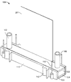
도 1은 예시적인 유체 분사기의 사시도이다.
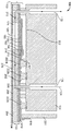
도 2는 예시적인 유체 분사기의 개략적인 단면도이다.
도 3은 예시적인 유체 분사기를 분해하여 일부를 도시한 저면 사시도이다.
도 4는 예시적인 유체 분사기의 단면 사시도이다.
도 5는 노즐 층을 도시하는 예시적인 유체 분사기의 저면 사시도이다.
도 6은 예시적인 유체 분사기의 펌핑 챔버 층의 상면 사시도이다.
도 6a는 펌핑 챔버를 근접 도시한 평면도이다.
도 7은 예시적인 유체 분사기의 박막 층의 평면도이다.
도 8은 예시적인 유체 분사기의 액츄에이터 층의 실시예의 단면을 도시한 사시도이다.
도 9는 예시적인 유체 분사기의 액츄에이터 층의 다른 실시예의 평면도이다.
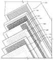
도 10은 예시적인 유체 분사기의 집적된 회로 삽입체의 저면 사시도이다.
도 11은 예시적인 다이에 본딩된 가요성 회로의 실시예를 도시한 개략도이다.
도 12는 예시적인 유체 분사 모듈에 본딩된 가요성 회로의 다른 실시예의 개략도이다.
도 13은 예시적인 유체 분사기의 가요성 회로, 집적된 회로 삽입체, 및 다이의 연결도이다.
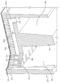
도 14는 예시적인 유체 분사기의 하우징 층의 사시도이다.
도 15a-15t는 예시적인 유체 분사기의 제조 방법을 도시한 개략도이다.
도 16은 88개의 다이를 가지는 웨이퍼의 개략도이다.
여러 도면들에서 유사한 도면부호 및 표시는 유사한 구성요소를 나타낸다. 1 is a perspective view of an exemplary fluid injector.
2 is a schematic cross-sectional view of an exemplary fluid injector.
3 is an exploded bottom perspective view of a portion of an exemplary fluid injector exploded.
4 is a cross-sectional perspective view of an exemplary fluid injector.
5 is a bottom perspective view of an exemplary fluid injector showing the nozzle layer.
6 is a top perspective view of a pumping chamber layer of an exemplary fluid injector.
6A is a plan view of the pumping chamber in a close-up view.
7 is a top view of a thin film layer of an exemplary fluid injector.
8 is a perspective view illustrating a cross section of an embodiment of an actuator layer of an exemplary fluid injector.
9 is a top view of another embodiment of an actuator layer of an exemplary fluid injector.
10 is a bottom perspective view of an integrated circuit insert of an exemplary fluid injector.
11 is a schematic diagram illustrating an embodiment of a flexible circuit bonded to an exemplary die.
12 is a schematic diagram of another embodiment of a flexible circuit bonded to an exemplary fluid injection module.
13 is a connection diagram of a flexible circuit, an integrated circuit insert, and a die of an exemplary fluid injector.
14 is a perspective view of a housing layer of an exemplary fluid injector.
15A-15T are schematic diagrams illustrating a method of making an exemplary fluid injector.
16 is a schematic of a wafer having 88 dies.
Like reference numbers and designations in the various drawings indicate like elements.
디지털 잉크 젯 프린팅과 같은 유체 액적 분사 중에, 프린트된 이미지에서의 부정확성 또는 결함을 회피하면서도 고속으로 그리고 저비용으로 프린트하는 것이 바람직하다. 예를 들어, 유체부피가 펌핑 챔버로부터 노즐까지 이동하여야 하는 거리를 감소시킴으로써, 다이 내의 액츄에이터로부터의 유체의 분사를 제어하기 위해서 전기 연결부를 포함하는 다이로부터 분리된 다이로부터 분리된 층을 구비함으로써, 이때 각각의 전기 연결부는 대응하는 유체 분사 요소에 인접하고, 그리고 유체 유입구 및 배출구 통로를 다이가 아니라 하우징 내에 포함으로써, 저비용의 유체 분사기가 고속으로 고품질의 이미지를 생성할 수 있다.
During fluid droplet injection, such as digital ink jet printing, it is desirable to print at high speed and low cost while avoiding inaccuracies or defects in the printed image. For example, by reducing the distance the fluid volume must travel from the pumping chamber to the nozzle, by having a layer separate from the die separated from the die comprising electrical connections to control the injection of fluid from the actuator in the die, Each electrical connection is then adjacent to the corresponding fluid ejection element, and the fluid inlet and outlet passages are contained within the housing, not the die, so that a low cost fluid injector can produce high quality images at high speed.
도 1을 참조하면, 예시적인 유체 분사기(100)는 유체 분사 모듈, 예를 들어 평행사변형 플레이트-형상의 프린트 헤드 모듈을 포함하는데, 그러한 모듈은 반도체 프로세싱 기술을 이용하여 제조된 다이(103)일 수 있다. 유체 분사기는 다이(103) 위쪽의 집적된 회로 삽입체(104) 및 이하에서 추가로 설명되는 하부 하우징(322)을 더 포함한다. 하우징(110)은 다이(103), 집적된 회로 삽입체(104), 및 하부 하우징(322)을 지지하고 둘러싸며, 하우징(110)을 프린트 바아에 연결하기 위해서 핀(152)을 가지는 장착 프레임(142)을 포함할 수 있다. 외부 프로세서로부터 데이터를 수신하고 그리고 구동 신호를 다이로 제공하기 위한 가요성 회로(210)가 다이(103)에 전기적으로 연결될 수 있고 그리고 하우징(110)에 의해서 정위치에서 유지될 수 있다. 튜빙(162, 166)은 하부 하우징(322) 내부에서 유입구 및 배출구 챔버(132, 136)에 연결되어(도 4 참조) 유체를 다이(103)로 공급할 수 있다. 유체 분사기(100)로부터 분사된 유체는 잉크일 수 있으나, 유체 분사기(100)는 다른 액체, 예를 들어, 생물학적 액체, 폴리머, 또는 전자 부품들을 형성하기 위한 액체에도 적합할 수 있을 것이다.
Referring to FIG. 1, an
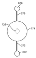
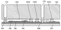
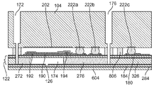
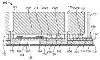
도 2를 참조하면, 유체 분사기(100)는 다이(103)의 일부인 기판(122), 예를 들어, 실리콘-온-인슐레이터(SOI) 웨이퍼, 그리고 집적된 회로 삽입체(104)를 포함할 수 있다. 집적된 회로 삽입체(104)는 트랜지스터(202)(도 2에는 하나의 분사 장치만이 도시되어 있고, 그에 따라 하나의 트랜지스터 만이 도시되어 있음)를 포함하고, 그리고 노즐(126)로부터의 유체 분사를 제어하기 위한 신호를 제공하도록 구성된다. 기판(122) 및 집적된 회로 삽입체(104)는 내부에 형성된 복수의 유체 유동 경로(124)를 포함한다. 단일 유체 경로(124)는 펌핑 챔버(174)로 연장된 유입구 채널(176)을 포함한다. 펌핑 챔버(174)는 노즐(126) 및 배출구 채널(172) 모두로 연장된다. 유체 경로(124)는 펌핑 챔버(174)를 유입구 채널(176) 및 배출구 채널(172)에 각각 연결하는 펌핑 챔버 유입구(276) 및 펌핑 챔버 배출구(272)를 더 포함한다. 유체 경로는 반도체 프로세싱 기술에 의해서, 예를 들어 에칭에 의해서 형성될 수 있다. 일부 실시예에서, 딥(deep) 반응성 이온 에칭을 이용하여 다이(103) 내의 층을 통해서 경로를 부분적으로 또는 전부 연장하는 직선형 벽의 피쳐(features)를 형성한다. 일부 실시예에서, 절연 층(284)을 에칭 스탑(stop)으로 이용하여, 절연 층에 인접한 실리콘 층(286)이 완전히 관통되게 에칭된다. 다이(103)는 박막(180), 그리고 노즐(126)이 내부에 형성되는 노즐 층(184)을 포함할 수 있고, 상기 박막은 펌핑 챔버의 하나의 벽을 형성하고 그리고 펌핑 챔버(174)의 내부를 액츄에이터에 노출되는 것으로부터 시일(seal)한다. 노즐 층(184)은 펌핑 챔버(174)의 반대쪽에 위치하는 절연 층(284)의 측부에 위치할 수 있다. 박막(180)은 하나의 실리콘 층으로 형성될 수 있다. 대안적으로, 박막(180)이 하나 또는 둘 이상의 산화물 층을 포함할 수 있고 또는 알루미늄 산화물(AlO2), 질화물, 또는 지르코늄 산화물(ZrO2)로 형성될 수 있다.
2, the
또한, 유체 분사기(100)는 기판(122)에 의해서 지지되고 개별적으로 제어가능한 액츄에이터(401)를 포함한다. 복수의 액츄에이터(401)가 액츄에이터 층(324)을 형성하는 것으로 간주되고(도 3 참조), 상기 액츄에이터들은 서로로부터 전기적으로 그리고 물리적으로 분리될 수 있으나 그럼에도 불구하고 층의 일부가 될 수 있다. 기판(122)은 액츄에이터와 박막(180) 사이에서 산화물과 같은 절연 물질(282)의 선택적인 층을 포함한다. 활성화되었을 때, 액츄에이터는 유체가 대응하는 유체 경로(124)의 노즐(126)로부터 선택적으로 분사되게 한다. 연관된 액츄에이터(401)와 함께 각각의 유동 경로(124)는 개별적으로 제어가능한 MEMS 유체 분사 유닛을 제공한다. 일부 실시예에서, 액츄에이터(401)의 활성화는 박막(180)을 펌핑 챔버(174) 내로 편향되게(deflect) 하여, 펌핑 챔버(174)의 부피를 감소시키고 그리고 노즐(126)의 외부로 유체를 강제한다. 액츄에이터(401)는 압전 액츄에이터일 수 있고 그리고 하부 전극(190), 압전 층(192), 및 상부 전극(194)을 포함할 수 있다. 대안적으로, 유체 분사 요소가 가열 요소일 수 있다.
The
도 3에 도시된 바와 같이, 유체 분사기(100)가 수직으로 적층된 복수의 층을 포함할 수 있다. 하부 하우징(322)은 집적된 회로 삽입체(104)에 본딩될 수 있다. 집적된 회로 삽입체(104)는 액츄에이터 층(324)에 본딩될 수 있다. 액츄에이터 층(324)은 박막(180)에 부착될 수 있다. 박막(180)은 펌핑 챔버 층(326)에 부착될 수 있다. 펌핑 챔버 층(326)은 노즐 층(184)에 부착될 수 있다. 일반적으로, 그러한 층은 평면을 따라서 이루어지는(occur) 유사한 물질 또는 유사한 요소를 포함할 수 있다. 모든 층은 대략적으로 동일한 폭을 가질 수 있고, 예를 들어, 각각의 층은 유체 분사기(100) 내의 다른 층의 길이 및 폭의 80% 이상인 길이 및 폭을 가질 수 있다. 도 3에 도시되지는 않았지만, 하우징(110)은 적어도 부분적으로 수직 적층 층들을 둘러쌀 수 있다.
As shown in FIG. 3, the
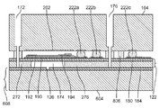
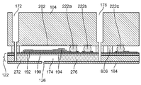
도 4를 참조하면, 유체가 유체 공급부로부터 하부 하우징(322)을 통해서, 집적된 회로 삽입체(104)를 통해서, 기판(122)을 통해서, 그리고 노즐 층(184) 내의 노즐(126)의 외부로 유동할 수 있다. 하부 하우징(322)은 유입구 챔버(132) 및 배출구 챔버(136)를 제공하기 위한 분할 벽(130)에 의해서 분할될 수 있다. 유체 공급부로부터의 유체가 유체 유입구 챔버(132) 내로, 하부 하우징(322)의 바닥 내의 유체 유입구(101)를 통해서, 하부 하우징(322)의 유체 유입구 통로(476)를 통해서, 유체 분사 모듈(103)의 유체 경로(124)를 통해서, 하부 하우징(322)의 유체 배출구 통로(472)를 통해서, 배출구(102) 외부로, 배출구 챔버(136) 내로, 그리고 유체 복귀부로 유동할 수 있다. 유체 분사 모듈(103)을 통과하는 유체의 일부가 노즐(126)로부터 분사될 수 있다.
Referring to FIG. 4, fluid flows from the fluid supply through the
각각의 유체 유입구(101) 및 유체 유입구 통로(476)가 하나, 둘 또는 그 초과의 유닛 행과 같은 복수의 MEMS 유체 분사 유닛의 평행 유입구 채널(176)에 공통적으로 그리고 유동적으로 연결된다. 유사하게, 각각의 유체 배출구(102) 및 각각의 유체 배출구 통로(472)가 하나, 둘 또는 그 초과의 유닛 행과 같은 다수의 MEMS 유체 분사 유닛의 평행 배출구 채널(172)에 공통적으로 그리고 유동적으로 연결된다. 각각의 유체 유입구 챔버(132)가 복수의 유체 유입구(101)에 공통된다. 그리고 각각의 유체 배출구 챔버(136)가 복수 배출구(102)에 공통된다.
Each
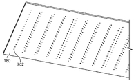
도 5를 참조하면, 노즐 층(184)이 노즐(126)의 행렬 또는 어레이를 포함할 수 있다. 일부 실시예에서, 노즐(126)이 직선형의 평행 행(504)들 및 평행 열(502)들로 정렬된다. 여기에서 사용된 바와 같이, 열은 프린트 방향에 수직이 아니라 프린트 방향에 평행한 축선에 근접하여 정렬된 노즐의 세트이다. 그러나, 열(502)은 프린트 방향에 정확하게 평행할 필요는 없고, 그 대신에 45°미만의 각도 만큼 오프셋될 수 있을 것이다. 또한, 행은 프린트 방향에 평행한 방향 대신에 프린트 방향에 수직한 축선에 근접하여 정렬된 노즐의 세트이다. 유사하게, 행(504)은 프린트 방향에 정확하게 수직일 필요가 없고, 45°미만의 각도 만큼 오프셋될 수 있을 것이다. 열(502)은 대략적으로 노즐 층(184)의 폭(W)을 따라서 연장할 수 있는 한편, 행(504)은 대략적으로 노즐 층(184)의 길이(L)를 따라서 연장할 수 있다.
Referring to FIG. 5, the
행렬 내의 열(502)의 수는 행(504)의 수 보다 클 수 있다. 예를 들어, 20개 미만의 행과 50개 초과의 열, 예를 들어 18개의 행과 80개의 열이 있을 수 있다. 각 행(504)의 노즐(126)이 행 내에서 인접한 노즐들로부터 균일하게 이격될 수 있다. 유사하게, 각 열 내의 노즐(126)이 열 내의 인접한 노즐들로부터 균일하게 이격될 수 있다. 또한,행과 열이 수직으로 정렬될 필요는 없다. 그 대신에, 행과 열 사이의 각도가 90°미만이 될 수 있다. 행 및/또는 열은 완벽하게 이격되지 않을 수 있다. 또한, 노즐(126)은 행 및/또는 열 내에서 직선을 따라서 놓이지 않을 수 있다.
The number of
노즐 행렬은 고밀도 행렬이 될 수 있고, 예를 들어 1 평방 인치 미만의 영역에서 550 내지 60,000 개의 노즐, 예를 들어, 1,440 또는 1,200 노즐을 가질 수 있다. 이하에서 추가적으로 설명하는 바와 같이, 이러한 고밀도 행렬이 달성될 수 있는데, 이는, 예를 들어, 분리된 집적된 회로 삽입체(104)가 액츄에이터들을 제어하기 위한 로직을 포함하고, 그에 따라 펌핑 챔버들, 및 그에 따른 노즐들이 서로 보다 근접하게 이격될 수 있기 때문이다. 즉, 박막 층은 박막을 가로질러 연장하는 전기적 연결부들을 실질적으로 포함하지 않을 수 있다.
The nozzle matrix can be a high density matrix and can have, for example, between 550 and 60,000 nozzles, for example 1,440 or 1,200 nozzles, in an area of less than 1 square inch. As will be described further below, such a high density matrix can be achieved, for example, where the separate
노즐(126)을 포함하는 영역은 1 인치 보다 긴 길이(L)를 가질 수 있고, 예를 들어 노즐 층의 길이(L)가 약 34 mm 일 수 있고, 그리고 노즐 층의 폭(W)이 1 인치 미만, 예를 들어 약 6.5 mm 일 수 있다. 노즐 층은 1 ㎛ 내지 50 ㎛, 예를 들어 20-40 ㎛, 예를 들어 30 ㎛의 두께를 가질 수 있다. 또한, 노즐 층은 사다리꼴 또는 평행사변형으로 성형될 수 있다. 노즐(126)은 KOH-에칭될 수 있고 그리고 정사각형 또는 원형일 수 있다.
The area comprising the
매체가 프린트 바아의 아래쪽을 통과할 때, 한 번의 패스에서 고밀도 행렬의 노즐이 유체를 매체 상으로 분사하여 고밀도의, 또는 600 dpi 초과의, 예를 들어 1200 dpi 또는 그 초과의 프린트 해상도를 가지는 픽셀들의 라인을 매체 상에 형성할 수 있을 것이다. 1200 dpi 또는 그 초과의 밀도를 얻기 위해서, 크기가 0.01 pL 내지 10 pL인, 예를 들어 2 pL인 유체 액적이 노즐들로부터 분사될 수 있다. 노즐은 1 ㎛ 내지 20 ㎛의 폭, 예를 들어 10 ㎛ 내지 20 ㎛의 폭, 예를 들어 약 15 ㎛ 또는 15.6 ㎛의 폭을 가질 수 있다.
When the media passes underneath the print bar, in one pass, a nozzle of high density matrix sprays the fluid onto the media to produce a pixel with a high, or greater than 600 dpi, for example, 1200 dpi or greater print resolution. Of lines may be formed on the medium. In order to obtain a density of 1200 dpi or more, fluid droplets of size between 0.01 pL and 10 pL, for example 2 pL, may be ejected from the nozzles. The nozzle may have a width of 1 μm to 20 μm, for example from 10 μm to 20 μm, for example about 15 μm or 15.6 μm.
노즐 층(184)은 실리콘으로 형성될 수 있다. 다른 실시예에서, 노즐 층(184)은 폴리이미드 또는 광 형성이 가능한 필름, 예를 들어 포토폴리머, 드라이 필름 포토레지스트, 또는 광 형성이 가능한 폴리이미드로 형성될 수 있으며, 이는 바람직하게 에칭이 필요하지 않도록 포토리소그래피에 의해서 패터닝될 수 있다.
The
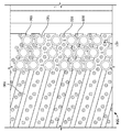
도 6을 참조하면, 펌핑 챔버 층(326)이 노즐 층(184)에 근접할 수 있고, 예를 들어 부착될 수 있다. 펌핑 챔버 층(326)은 펌핑 챔버(174)를 포함한다. 각각의 펌핑 챔버(174)는 연관 노즐의 외측으로 액체를 강제하는 하나 이상의 변형가능한 벽을 가지는 공간일 수 있다. 펌핑 챔버들은 가능한 한 가장 높은 충진 밀도를 제공하는 형상을 가질 수 있다. 도 6에 도시된, 펌핑 챔버(174)는 대략적으로 원형인 형상을 가질 수 있고 그리고 일반적으로 측벽(602)에 의해서 형성될 수 있다. 펌핑 챔버는 정확히 원형이 아닐 수 있고, 즉, 준-원형 형상일 수 있고 그리고 타원형, 달걀형일 수 있으며 또는 직선형과 곡선형 측부들의 조합을 가질 수 있고, 예를 들어 육각형, 팔각형, 또는 다각형일 수 있다. 또한, 펌핑 챔버는 가장 넓은 폭을 따라서 약 100 ㎛ 내지 400 ㎛, 예를 들어 약 125 ㎛ 내지 250 ㎛가 될 수 있다. 펌핑 챔버(174)의 높이는 펌핑 챔버의 가장 좁은 폭의 50% 미만일 수 있다.
Referring to FIG. 6, the
각 펌핑 챔버는 펌핑 챔버 층(326)으로부터 연장하고 그리고 그 내부에 형성되는 펌핑 챔버 유입구(276) 및 펌핑 챔버 배출구(272)를 구비할 수 있다. 펌핑 챔버 유입구(276) 및 펌핑 챔버 배출구(272)는 펌핑 챔버(174)와 동일한 평면을 따라서 연장할 수 있고 그리고 서로 동일한 축선을 따라서 연장할 수 있다. 펌핑 챔버 유입구(276) 및 배출구(272)는 펌핑 챔버(174) 보다 상당히 좁은 폭을 가질 수 있고, 그 폭은 유입구 또는 배출구의 가장 작은 비-높이(non-height) 치수가 된다. 펌핑 챔버 유입구(276) 및 배출구(272)의 폭은 펌핑 챔버(174)의 폭의 10% 미만과 같이 30% 미만이 될 수 있다. 펌핑 챔버 유입구(276) 및 펌핑 챔버 배출구(272)는 펌핑 챔버(174)로부터 연장하는 평행한 벽들을 포함할 수 있으며, 이때 평행한 벽들 사이의 거리가 폭이 된다. 도 6a에 도시된 바와 같이, 펌핑 챔버 유입구(276)의 형상은 펌핑 챔버 배출구(272)와 동일할 수 있다.
Each pumping chamber may have a pumping
펌핑 챔버 층은 유입구 채널(172) 및 배출구 채널(172) 그리고 펌핑 챔버 유입구(276) 및 배출구(272)로부터 분리된 채널들을 포함하지 않는다. 다시 말해서, 펌핑 챔버 유입구(276) 및 펌핑 챔버 배출구(272)와 별개로, 유체 통로가 펌핑 챔버 층을 통해서 수평으로 연장하지 않는다. 유사하게, 유입구 및 배출구 채널(176, 172)과 별개로, 유체 통로가 펌핑 챔버 층을 통해서 수직으로 연장하지 않는다. 펌핑 챔버 층(326)은 디센더를 포함하지 않고, 즉, 펌핑 챔버(174)로부터 노즐(126)로 연장하는 채널을 포함하지 않는다. 그 대신에, 펌핑 챔버(174)는 노즐 층(184) 내의 노즐(126)과 직접 접한다(abut). 또한, 유입구 채널(176)은 다이(103)를 통해서 대략적으로 수직으로 연장하여 펌핑 챔버 유입구(276)와 교차한다. 펌핑 챔버 유입구(276)는 다시(in turn) 펌핑 챔버 층(326)을 통해서 수평으로 연장하여 펌핑 챔버(174)와 유체적으로 연결된다. 유사하게, 배출구 채널(172)은 다이(103)를 통해서 대략적으로 수직으로 연장하여 펌핑 챔버 배출구(272)와 교차한다.
The pumping chamber layer does not include channels separate from
도 6a에서 평면도로 도시된 바와 같이, 유체 유입구(176) 및 유체 배출구(172)와 교차하는 펌핑 챔버 유입구(276) 및 배출구(272)의 부분(672, 676)은 펌핑 챔버 유입구(276) 및 펌핑 챔버 배출구(272)의 나머지 보다 폭 또는 직경이 더 크거나 더 넓을 수 있다. 또한, 부분(672, 676)은 대략적으로 원형인 형상을 가질 수 있고, 즉 유입구 채널(176) 및 배출구 채널(172)이 튜브형 형상을 가질 수 있다. 또한, 연관된 노즐(126)이 펌핑 챔버(174)의 바로 아래쪽에, 그리고 펌핑 챔버(174)의 중심에 위치될 수 있다.
As shown in plan view in FIG. 6A, pumping
도 6을 참조하면, 펌핑 챔버(174)는 행과 열을 가지는 행렬로 정렬될 수 있다. 행과 열 사이의 각도가 90°미만일 수 있다. 단일 다이에서, 예를 들어 1 평방 인치 미만의 영역에서, 550 내지 60,000 개의 펌핑 챔버, 예를 들어, 1,440 또는 1,200 개의 펌핑 챔버가 있을 수 있다. 펌핑 챔버의 높이는 50 ㎛ 미만, 예를 들어 25 ㎛ 미만일 수 있다. 또한, 도 2를 다시 참조하면, 각 펌핑 챔버(174)가 대응하는 액츄에이터(401)에 인접할 수 있고, 예를 들어, 액츄에이터(401)의 바로 아래쪽에서 액츄에이터(401)와 정렬될 수 있다. 펌핑 챔버는 대응하는 액츄에이터로부터 노즐까지의 거리의 80% 이상의 거리를 통해서 연장할 수 있다.
Referring to FIG. 6, the pumping
노즐 층(184)과 유사하게, 펌핑 챔버 층(326)이 실리콘 또는 광 형성이 가능한 필름으로 형성될 수 있다. 광 형성이 가능한 필름은, 예를 들어, 포토폴리머, 드라이 필름 포토레지스트, 또는 광 형성이 가능한 폴리이미드일 수 있다.
Similar to the
박막 층(180)은 펌핑 챔버 층(326)에 인접할 수 있고, 예를 들어 부착될 수 있다. 도 7을 참조하면, 박막 층(180)이 박막 층(180)을 관통하는 개구(702)를 포함할 수 있다. 개구는 유체 경로(124)의 일부일 수 있다. 즉, 유입구 채널(176) 및 배출구 채널(172)은 박막 층(180)의 개구(702)를 통해서 연장할 수 있다. 그에 따라, 개구(702)는 행과 열을 가지는 행렬을 형성할 수 있다. 박막 층(180)은, 예를 들어, 실리콘으로 형성될 수 있다. 박막은 비교적 얇을 수 있고, 예를 들어 25 ㎛ 미만, 예를 들어 약 12 ㎛일 수 있다.
액츄에이터 층(324)은 박막 층(180)에 인접할 수 있고, 예를 들어, 부착될 수 있다. 액츄에이터 층은 액츄에이터(401)를 포함한다. 액츄에이터는 가열 요소일 수 있다. 그 대신에, 도 2, 8 및 9에 도시된 바와 같이, 액츄에이터(401)가 압전 요소일 수 있다.
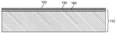
도 2, 8 및 9에 도시된 바와 같이, 각각의 액츄에이터(401)는 하부 전극(190) 및 상부 전극(194)을 포함하는 2개의 전극들 사이의 압전 층(192)을 포함한다. 압전 층(192)은, 예를 들어, 리드 지르코늄 티타네이트("PZT") 필름이 될 수 있다. 압전 층(192)은 약 1 내지 25 미크론의 두께를 가질 수 있고, 예를 들어 약 1 ㎛ 내지 4 ㎛의 두께를 가질 수 있다. 압전 층(192)은 벌크 압전 물질로부터 형성될 수 있고 또는 졸-겔 프로세스 혹은 물리기상증착 장치를 이용한 스퍼터링에 의해서 형성될 수 있다. 스퍼터링된 압전 층은 원주형(columnar) 구조를 가질 수 있는 한편, 벌크 및 졸-겔 압전 층은 보다 랜덤한 구조를 가질 수 있다. 일부 실시예에서, 압전 층(192)은, 도 8에 도시된 바와 같이, 모든 액츄에이터들을 가로질러 그 사이에서 연장하는 연속적인 압전 층이다. 대안적으로, 도 2 및 9에 도시된 바와 같이, 압전 층이 세그먼트화(단편화)될 수 있고, 그에 따라 인접한 액츄에이터들의 압전 부분들이 서로 접촉하지 않게 되고, 예를 들어, 압전 층 내에 인접 액츄에이터들을 분리하는 갭이 있게 된다. 예를 들어, 압전 층(192)은 대략적으로 원형 형상으로 형성된 섬(islands)일 수 있다. 개별적으로 형성된 섬들은 에칭에 의해서 만들어질 수 있다. 도 2에 도시된 바와 같이, 압전 층(192)이 연속적이 아니라면, 바닥 보호 층(214), 예를 들어, 절연 층, 예를 들어 SU8 또는 산화물이 상부 및 하부 전극들 간의 상호 접촉을 유지하는데 사용될 수 있다. 상부 보호 층(210), 예를 들어 절연 층, 예를 들어, SU8 또는 산화물을 이용하여 추가적인 프로세싱 단계 동안 및/또는 모듈 작업 동안 수분으로부터 액츄에이터를 보호할 수 있다.
As shown in FIGS. 2, 8 and 9, each
일부 실시예에서 구동 전극 층이 되는 상부 전극(194)이 전도성 물질로 형성된다. 구동 전극으로서, 상부 전극(194)이 제어부에 연결되어 유체 분사 사이클 동안 적절한 시간에 압전 층(192)을 가로질러 전압 차를 제공한다. 상부 전극(194)은 패터닝된 전도성 피스를 포함할 수 있다. 예를 들어, 도 8 및 9에 도시된 바와 같이, 상부 전극(194)이 링 전극일 수 있다. 대안적으로, 상부 전극(194)이 중앙 전극일 수 있고 또는 내측 및 링 전극들 모두를 포함하는 듀얼 전극일 수 있다.
In some embodiments, the
일부 실시예에서 기준 전극 층이 되는 하부 전극(190)이 전도성 물질로 형성된다. 하부 전극(190)은 접지에 대한 연결을 제공할 수 있다. 하부 전극은 박막 층(180) 상에 직접적으로 패터닝될 수 있다. 또한, 도 8 및 9에 도시된 바와 같이, 하부 전극(190)은 복수의 액츄에이터에 공통되고 그리고 복수의 액츄에이터를 가로질러 걸쳐진다(span). 상부 전극(194) 및 하부 전극(190)은 금, 니켈, 니켈 크롬, 구리, 이리듐, 이리듐 산화물, 플래티늄, 티타늄, 티타늄 텅스텐, 인듐 주석 산화물, 또는 이들의 조합으로 형성될 수 있다. 이러한 실시예에서, 보호 층(210 및 214)들이 연속적일 수 있고 그리고 펌핑 챔버(174) 및 리드(222) 위쪽에 홀들을 구비할 수 있다. 대안적으로, 각각의 액츄에이터(401)에 대해서 분리된 하부 전극(190)이 있을 수 있다. 그러한 구성에서, 도 2에 도시된 바와 같이, 보호 층(210 및 214)이 액츄에이터(401)의 엣지들 주위에만 위치될 수 있다. 도 8에 도시된 바와 같이, 접지 개구(812)가 접지로의 연결을 위해서 압전 층(192)을 통해서 형성될 수 있다. 대안적으로, 도 9에 도시된 바와 같이, 접지 연결부가 하부 전극(190)을 따라서 어딘가에 제조되도록, 예를 들어 액츄에이터 층(324)의 길이(L)에 평행하게 연장하는 하부 전극(190)의 부분을 따라서 제조되도록, PZT가 에칭에 의해서 제거될 수 있다.
In some embodiments, the
압전 층(192)은 상부 전극(194)과 하부 전극(190) 사이의 압전 층(192)을 가로질러 인가되는 전압에 응답하여 기하학적 형상을 변화시킬 수 있다. 압전 층(192)의 기하학적 형상의 변화는 박막(180)을 휘어지게 하고, 이는 다시 펌핑 챔버(174)의 부피를 변화시키고 그리고 내부의 유체를 가압하여, 노즐(126)을 통해서 유체를 제어가능하게 강제한다.
The
도 8에 도시된 바와 같이, 액츄에이터 층(324)은, 이하에서 설명하는 바와 같이, 가요성 회로에 연결하기 위한 입력 전극(810)을 더 포함할 수 있다. 입력 전극(810)은 액츄에이터 층(324)의 길이(L)를 따라서 연장한다. 입력 전극(810)은 액츄에이터 층(324)의 동일한 표면을 따라서 상부 전극(194) 및 하부 전극(190)으로서 위치될 수 있다. 대안적으로, 입력 전극(810)이 액츄에이터 층(324)의 측부를 따라서, 예를 들어 상기 표면에 수직인 얇은 표면 상에서 집적된 회로 삽입체(104)에 대한 본딩을 따라서 위치될 수 있다.
As shown in FIG. 8, the
도 8 및 9를 참조하면, 압전 요소(401)가 행과 열의 행렬로 배열될 수 있다(다른 요소들이 보다 명확하게 도시될 수 있도록, 압전 요소(401)의 일부만이 도 8 및 9에 도시되어 있음). 개구(802)가 액츄에이터 층(324)을 통해서 연장할 수 있다. 개구(802)는 유체 경로(124)의 일부일 수 있다. 즉, 유입구 채널(176) 및 배출구 채널(172)이 액츄에이터 층(324)의 개구(802)를 통해서 연장할 수 있다. 압전 물질이 에칭으로 제거된다면, 도 2 및 9에 도시된 바와 같이, SU8과 같은 배리어 물질(806)이 박막 층(180)과 집적된 회로 삽입체(104) 사이에 배치되어 개구(802)를 형성할 수 있다. 다시 말해서, 배리어 물질(806)이 범프로서 형성될 수 있고, 그러한 범프를 통해서 개구(802)가 연장할 수 있다. 이하에서 설명하는 바와 같이, 압전 층이 도 8에 도시된 바와 같이 중실(solid) 층이라면, 유체 누설로부터 전기 요소를 보호하기 위한 시일로서 작용하기 위해서 배리어 물질(806)이 또한 사용될 수 있다.
8 and 9, the
이하에서 추가적으로 설명하는 바와 같이, 액츄에이터 층(324)은 액츄에이터(401) 주위로 연장하는 트레이스 또는 전기 연결부들을 포함하지 않는다. 그 대신에 액츄에이터를 제어하기 위한 트레이스가 집적된 회로 삽입체(104) 내에 위치된다.
As will be described further below,
집적된 회로 삽입체(104)는 액츄에이터 층(401)에 근접할 수 있고, 일부 경우에 액츄에이터 층에 부착된다. 집적된 회로 삽입체(104)는 액츄에이터(401)의 작동을 제어하기 위한 신호를 제공하도록 구성된다. 도 10을 참조하면, 집적된 회로 삽입체(104)는, 예를 들어 반도체 제조 기술에 의해서, 내부에 집적 회로가 형성된 마이크로칩일 수 있다. 일부 실시에서, 집적된 회로 삽입체(104)가 주문형 집적 회로(ASIC) 요소이다. 집적된 회로 삽입체(104)는 액츄에이터를 제어하기 위한 신호를 제공하기 위한 로직을 포함할 수 있다.
The
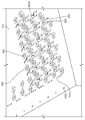
여전히 도 10을 참조하면, 집적된 회로 삽입체(104)는 트랜지스터와 같은 복수의 집적된 스위칭 요소(202)를 포함할 수 있다. 집적된 스위칭 요소(202)는 행과 열의 행렬로 정렬될 수 있다. 일 실시예에서, 모든 액츄에이터(201)에 대해서 하나의 집적된 스위칭 요소(202)가 존재한다. 다른 실시예에서, 모든 액츄에이터(401)에 대해서 하나 보다 많은, 예를 들어 2개의 집적된 스위칭 요소(202)가 존재한다. 대응 액츄에이터의 일부를 하나의 트랜지스터로 구동하고 그리고 액츄에이터의 다른 부분을 제 2 트랜지스터로 구동하여 절반의 전압이 요구되도록 하기 위해서, 또는 하나의 트랜지스터 보다 더 복잡한 파형을 허용하기 위한 아날로그 스위치를 생성하기 위해서, 2개의 집적된 회로 요소(202)가 여분(redundancy)을 제공하는데 있어서 유리할 수 있다. 또한, 만약 4개의 집적된 회로 요소(202)가 사용된다면, 여분의 아날로그 스위치가 제공될 수 있다. 하나의 집적된 회로 요소(202) 또는 복수의 집적된 스위칭 요소(202)가 대응하는 액츄에이터(401)에 인접하여 또는 그 상부에 위치될 수 있다. 즉, 축선이 펌핑 챔버(174)를 통해 그리고 트랜지스터를 통해, 노즐(126)을 통해서, 또는 2개의 스위칭 요소들 사이에서 연장할 수 있다. 각각의 집적된 스위칭 요소(202)가 온/오프 스위치로서 작용하여 액츄에이터(401)들 중 하나의 상부 전극(194)을 구동 신호 소오스에 선택적으로 연결한다. 구동 신호 전압은 집적된 회로 삽입체(104) 내의 내부 로직을 통해서 전달된다.
Still referring to FIG. 10, the
집적된 회로 삽입체(104) 내의 집적된 스위칭 요소(202), 예를 들어 트랜지스터가 리드(222a), 예를 들어 골드 범프를 통해서 액츄에이터(401)에 연결될 수 있다. 또한, 리드(222a)들의 세트, 예를 들어 골드 범프들이 집적된 회로 삽입체(104)의 엣지를 따라서 정렬될 수 있다. 각각의 세트가 복수의 리드(222b), 예를 들어 3개의 리드(222b)를 포함할 수 있다. 집적된 스위칭 요소(202)의 모든 열에 대해서 하나의 리드(222b) 세트가 존재할 수 있다. 리드(222b)는, 예를 들어 액츄에이터 층(324)의 접지 개구(812)를 통해서, 집적된 회로 삽입체(104) 내의 로직을 다이(103) 상의 접지 전극(190)과 연결하도록 구성될 수 있다. 또한, 리드(222c), 예를 들어 골드 범프가 집적된 회로 삽입체(104)의 엣지에 근접하여 위치될 수 있다. 리드(222c)는, 이하에서 설명하는 바와 같이, 가요성 회로(201)와의 연결을 위해서, 집적된 회로 삽입체(104) 내의 로직을 입력 전극(810)과 연결하도록 구성될 수 있다. 리드들(222a, 222b, 222c)가 펌핑 챔버의 위쪽이 아닌 기판의 구역(region) 상에 위치된다.
An
도 10에 도시된 바와 같이, 집적된 회로 삽입체(104)가 집적된 회로 삽입체(104)를 관통하는 개구(902)를 포함할 수 있다. 층 내에서 전기 연결을 위한 공간을 남기기 위해서, 개구들은 대향 측부 보다 집적된 스위칭 요소(202)를 포함하는 집적된 회로 삽입체(104)의 측부에 근접하여 더 좁을 수 있다. 개구(902)는 유체 경로(124)의 일부일 수 있다. 즉, 유입구 채널(176) 및 배출구 채널(172)이 집적된 회로 삽입체(104)의 개구(902)를 통해서 연장할 수 있다. 유체 경로(124)와 집적된 회로 삽입체(104) 내의 로직과 같은 전자기기 사이의 유체 누설을 방지하기 위해서, 예를 들어 티타늄 또는 탄탈륨의 금속과 같이, 혹은 예를 들어 실리콘 산화물, 저압 화학기상증착(LPCVD) 산화물, 알루미늄 산화물, 또는 실리콘 질화물/실리콘 산화물의 비-금속 물질과 같이, 양호한 산소 배리어를 제공하는 그리고 양호한 습윤(wetting) 성질을 가지는 물질로 유체 통로(124)를 코팅하여 통로를 통한 유체의 이송을 촉진할 수 있을 것이다. 그러한 코팅은 전기도금, 스퍼터링, CVD, 또는 다른 증착 프로세스에 의해서 도포될 수 있다. 또한, 배리어 물질(806)은 집적된 회로 요소 내의 로직을 유체 누설로부터 보호하기 위해서 사용될 수 있다. 다른 실시예에서, 예를 들어 스핀-코팅에 의해서, 배리어 층, 예를 들어 SU8이 집적된 회로 삽입체(104)와 다이(103) 사이에 위치될 수 있다. 배리어 층은 개구(902)를 위한 개구부를 남기도록 패터닝되는 다이(103) 및 집적된 회로 삽입체(104)의 모든, 또는 거의 모든 길이 및 폭에 걸쳐 연장할 수 있다.
As shown in FIG. 10, the
유체 분사기(100)가 가요성 인쇄 회로 기판 또는 가요성 회로(201)를 더 포함할 수 있다. 가요성 회로(201)는 예를 들어 플라스틱 기판 상에 형성될 수 있다. 가요성 회로(201)는 유체 분사기(100)를 프린터 시스템 또는 컴퓨터(도시하지 않음)에 전기적으로 연결하도록 구성된다. 가요성 회로(201)가, 유체 분사 요소, 예를 들어 액츄에이터(401)를 구동하기 위해서, 프린트 시스템의 외부 프로세스를 위한 이미지 데이터 및 타이밍 신호와 같은 데이터를 다이(103)로 전송하는데 사용된다.
The
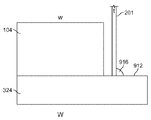
도 11 및 12에 도시된 바와 같이, 가요성 회로(201)가 접착제를 이용하여, 예를 들어 에폭시를 이용하여 액츄에이터 층(324)에 본딩될 수 있다. 일 실시예에서, 도 11에 도시된 바와 같이, 액츄에이터 층(324)이 집적된 회로 삽입체(104)의 폭(w) 보다 큰 폭(W)을 가질 수 있다. 그에 따라, 액츄에이터 층(324)은 집적된 회로 삽입체(104)를 지나서 연장하여 렛지(912)를 생성할 수 있다. 가요성 회로(201)는 집적된 회로 삽입체(104)와 나란히(alongside) 연장할 수 있으며, 그에 따라 액츄에이터 층(324)과 접촉하는 표면에 대해서 수직인 집적된 회로 삽입체(104)의 엣지가 가요성 회로(201)에 대해서 평행하게 연장한다. 가요성 회로(201)가 두께(t)를 가질 수 있다. 가요성 회로는 두께(t) 보다 상당히 큰 높이 및 폭을 가질 수 있다. 예를 들어, 가요성 회로(201)의 폭은 대략적으로 다이의 길이가, 예를 들어 33 mm가 될 수 있는 한편, 두께(t)는 100 ㎛ 미만, 예를 들어 12 내지 100 ㎛, 예를 들어 25-50 ㎛, 예를 들어 약 25 ㎛가 될 수 있다. 예를 들어 두께(t)를 가지는 가장 좁은 엣지는 액츄에이터 층(324)의 상부 표면에, 예를 들어 집적된 회로 삽입체(104)에 본딩되는 액츄에이터 층(324)의 표면에 본딩될 수 있다.
As shown in FIGS. 11 and 12, the
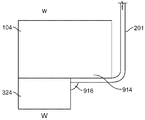
도 12에 도시된 다른 실시예에서, 집적된 회로 삽입체(104)는 액츄에이터 층(324)의 다이의 폭(W) 보다 큰 폭(w)을 가질 수 있다. 그에 따라, 집적된 회로 삽입체(104)는 액츄에이터 층(324)을 지나서 연장하여 렛지(914)를 형성할 수 있다. 가요성 회로(201)는 렛지(914) 주위에 벤딩되어 삽입체(104)에 부착될 수 있다. 가요성 회로(201)는 집적된 회로 삽입체(104)와 나란히 연장할 수 있으며, 그에 따라 액츄에이터 층(324)과 접촉하는 표면에 대해서 수직인 집적된 회로 삽입체(104)의 엣지가 가요성 회로(201)의 부분에 대해서 평행하게 연장한다. 가요성 회로(201)는 렛지(914) 주위로 벤딩될 수 있고, 그에 따라 가요성 회로(201)의 일부가 집적된 회로 삽입체(104)의 바닥에 즉, 액츄에이터 층(324)과 접촉하는 표면에 부착된다. 도 11의 실시예에서와 같이, 가요성 회로가 두께(t) 보다 상당히 큰 높이 및 폭을 가질 수 있다. 예를 들어, 가요성 회로(201)의 폭은 대략적으로 다이의 길이, 예를 들어 33 mm가 될 수 있는 한편, 두께(t)는 100 ㎛ 미만, 예를 들어 12 내지 100 ㎛, 예를 들어 25-50 ㎛, 예를 들어 약 25 ㎛가 될 수 있다. 예를 들어 두께(t)를 가지는 가장 좁은 엣지는 액츄에이터 층(324)에 인접할 수 있는데, 예를 들어 집적된 회로 삽입체(104)에 본딩되는 표면에 수직인 액츄에이터 층(324)의 표면에 인접할 수 있다.
In another embodiment shown in FIG. 12, the
도시하지는 않았지만, 가요성 회로(201)는 안정성을 위해서 기판(103)에 인접할 수 있다. 가요성 회로(201)는 액츄에이터 층(324) 상의 입력 전극(810)과 전기적으로 연결될 수 있다. 땜납과 같은 전도성 물질의 작은 비드(bead)를 이용하여 가요성 회로(201)를 입력 전극(810)과 전기적으로 연결할 수 있다. 또한, 유체 분사기(100)마다 단지 하나의 플렉스가 필요하다.
Although not shown, the
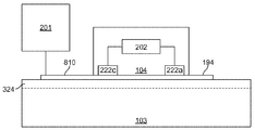
가요성 회로(201), 집적된 회로 삽입체(104), 및 다이(103)의 연결도가 도 13에 도시되어 있다. 가요성 회로(201)로부터의 신호가 입력 전극(810)을 통해서 전송되고, 리드(222c)를 통해서 집적된 회로 삽입체(104)로 전달되고, 집적된 회로 요소(202)와 같은 집적된 회로 삽입체(104)에서 프로세싱되고, 그리고 리드(222a)에서 출력되어, 액츄에이터(401)의 상부 전극(194)을 활성화시키고 그에 따라 액츄에이터(401)를 구동한다.
A connection diagram of the
집적된 회로 요소(202)는 데이터 플립-플롭(flip-flops), 래치 플립-플롭, OR 게이트, 및 스위치를 포함할 수 있다. 집적된 회로 삽입체(104) 내의 로직은 클록 라인, 데이터 라인, 래치 라인, 올-온 라인, 및 파워 라인을 포함할 수 있다. 신호는 데이터 라인을 통해서 데이터 플립-플롭으로 데이터를 전송함으로써 프로세싱된다. 이어서, 클록 라인은 데이터가 유입될 때 데이터를 클록킹한다(clock). 데이터가 연속적으로 유입되며, 그에 따라 제 1 플립-플롭내로 유입되는 데이터의 제 1 비트는 다음 데이터 비트가 유입될 때 시프트 다운된다. 모든 데이터 플립-플롭이 데이터를 포함한 후에, 데이터 플립-플롭으로부터 래치 플립-플롭으로 그리고 유체 분사 요소(401) 상으로 데이터를 이동(shift)하기 위해서 펄스가 래치 라인을 통해서 송신된다. 만약 래치 플립-플롭으로부터의 신호가 높다면, 스위치가 턴온되고 그리고 유체 분사 요소(401)를 구동하기 위해서 신호를 통과시켜 송신한다. 만약 신호가 낮다면, 스위치는 오프 상태를 유지하고 그리고 유체 분사 요소(401)는 활성화되지 않는다.
Integrated
전술한 바와 같이, 유체 분사기(100)는 도 14에 도시된 하부 하우징을 더 포함할 수 있다. 유체 유입구(101) 및 유체 배출구(102)가 하부 하우징(322)의 길이(l)를 따라서 2개의 평행한 라인들로 연장될 수 있다. 각 라인, 즉 유체 유입구(101) 또는 유체 배출구(102)의 각 라인이 하부 하우징(322)의 엣지에 인접하여 연장할 수 있다.
As described above, the
수직 유체 유입구(101)는 하부 하우징(322)의 수평 유체 유입구 통로(476)까지 연장할 수 있다. 유사하게, 수직 유체 배출구(102)는 하부 하우징(322)의 수평 유체 배출구 통로(472)(도 14에는 도시되지 않음)까지 연장할 수 있다. 유체 유입구 통로(476) 및 유체 배출구 통로(472)가 서로 동일한 형상 및 부피를 가질 수 있다. 유체 유입구 통로 및 유입구는 함께 전체적으로 "L"자 형상을 가질 수 있다. 또한, 각각의 유체 유입구 및 유체 배출구 통로(476, 472)가 하부 하우징(322)의 폭(w)을 가로질러 서로 평행하게 연장할 수 있고, 예를 들어, 하우징 부품의 폭의 70-99%에 걸쳐서, 예를 들어 하우징 부품의 폭의 80-95%, 또는 85%에 걸쳐서 연장한다. 또한, 유체 유입구 통로(476) 및 유체 배출구 통로(472)는 하부 하우징(322)의 길이(l)를 가로질러 교호적으로 배치될 수 있다(alternate).
The vertical
유체 유입구 통로(476) 및 유체 배출구 통로(472)는 각각 동일한 방향으로 즉, 평행한 축선들을 따라서 연장할 수 있다. 또한, 도 4에 도시된 바와 같이, 유체 유입구 통로(476)는 복수의 유체 유입구 채널(176)에 각각 연결될 수 있다. 각각의 유체 유입구 채널(176)은 유체 유입구 통로(476)로부터 수직으로 연장할 수 있다. 유사하게, 각각의 유체 배출구 통로(472)는 복수의 유체 배출구 채널(172)에 이어질 수 있으며, 상기 유체 배출구 채널(172)의 각각은 유체 배출구 통로(472)로부터 수직으로 연장한다.
그에 따라, 유체 공급부로부터의 유체는 유체 유입구 챔버(132) 내로, 하우징(322) 내의 유체 유입구(101)를 통해서, 하부 하우징(322)의 유체 유입구 통로(476)를 통해서, 유체 분사 모듈(103)의 복수의 유체 경로를 통해서, 하부 하우징(322)의 유체 배출구 통로(472)를 통해서, 배출구(102)를 통해서 외부로, 배출구 챔버(136)의 내로, 그리고 유체 복귀부로 유동할 수 있다.
Thus, fluid from the fluid supply is introduced into the
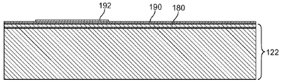
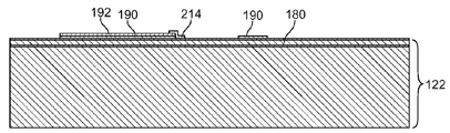
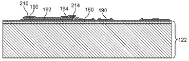
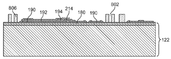
도 15a-15t는 유체 분사기(100)를 제조하는 예시적인 방법을 도시한다. 하부 전극(190)은 박막(180)을 가지는 웨이퍼(122), 예를 들어 실리콘-온-옥사이드(SOI) 웨이퍼와 같은 반도체 웨이퍼 상에 스퍼터링된다(도 15a 참조). 이어서, 압전 층(192)이 하부 전극(190) 위에 스퍼터링되고(도 15b 참조) 그리고 에칭된다(도 15c 참조). 하부 전극(190)이 에칭될 수 있고(도 15d 참조) 그리고 바닥 보호 층(214)이 도포된다(도 15e 참조). 이어서, 상부 전극(194)이 스퍼터링될 수 있고 그리고 에칭될 수 있고(도 15f 참조), 그리고 상부 보호 층(210)이 도포된다(도 15g 참조). 누설 유체로부터 유체 경로(124)를 보호하기 위한 배리어 물질(806)이 이어서 도포될 수 있고, 그 사이에 개구(802)를 형성할 수 있다(도 15h 참조). 이어서, 개구(702)가 박막 층(180)내로 에칭되고(도 15i 참조), 그에 따라 그 개구들이 개구(802)와 정렬된다. 선택적으로, 산화물 층(288)이 에칭 스탑으로서 사용될 수 있다.
15A-15T illustrate an example method of making a
집적된 회로 삽입체(104), 예를 들어 ASIC 웨이퍼가 집적된 회로 요소(202) 및 리드(222a, 222b, 222c)와 함께 형성될 수 있다(도 15j 참조). 도 15k 및 15l에 도시된 바와 같이, 딥 반응성 이온 에칭을 이용하여, 개구(902)가 집적된 회로 삽입체(104) 내로 에칭되어 유체 경로의 일부를 형성할 수 있다. 개구(902)가 집적된 회로 삽입체(104)의 바닥 표면 내로 즉, 집적된 회로 요소(202)를 포함하는 표면 내로 먼저 에칭될 수 있다(도 15k 참조). 이어서, 개구(902)는 보다 큰 직경의 홀을 집적된 회로 삽입체(104)의 상부로부터 에칭함으로써 완성될 수 있다(도 15l 참조). 보다 큰 직경의 홀은 에칭 프로세스를 보다 용이하게 만들고 그리고 유체 부식으로부터 개구(902)를 보호하기 위해서 보호 금속 층이 개구(902)로 스퍼터링될 수 있게 한다.
An
에칭에 이어서, 집적된 회로 삽입체(104) 및 웨이퍼(122)가 BCB 또는 폴리이미드 또는 에폭시와 같은 스펀-온(spun-on) 접착제를 이용하여 함께 본딩될 수 있다(도 15m 참조). 대안적으로, 접착제가 집적된 회로 삽입체(104) 및 웨이퍼(122) 상으로 스프레이될 수 있다. 집적된 회로 삽입체(104) 및 웨이퍼(122)의 본딩이 실시되며, 그에 따라 집적된 회로 삽입체의 개구(902), 펌핑 챔버 층의 개구(802), 및 박막 층(180)의 개구(702)가 정렬되어 유체 유입구 및 배출구 채널(172, 176)을 형성할 수 있다.
Following etching, the
이어서, 웨이퍼(122)의 핸들 층(601)이 연마되고(ground) 그리고 폴리싱될 수 있다(도 15n 참조). 도시하지는 않았지만, 집적된 회로 삽입체(104)는 연마 동안에 보호되어야 할 필요가 있을 것이다. 펌핑 챔버 유입구 및 배출구(276, 272)를 포함하는 펌핑 챔버(174)가 웨이퍼(122)의 바닥으로부터 즉, 집적된 회로 삽입체(104)의 반대쪽의 측부로부터 웨이퍼(122) 내로 에칭될 수 있다(도 15o 참조). 선택적으로, 산화물 층(288)이 에칭 스탑으로서 사용될 수 있다. 이어서, 노즐 층(184) 내로 이미 에칭된 노즐(126)을 포함하는 노즐 웨이퍼(608)가 저온 본딩을 이용하여, 예를 들어 BCB와 같은 에폭시를 이용한 본딩을 이용하여, 또는 저온 플라즈마 활성화 본딩을 이용하여, 웨이퍼(122)에 본딩될 수 있다(도 15p 참조). 예를 들어, 구조물이 이미 본딩된 압전 층(122)에 손상을 입히는 것을 방지하기 위해서, 노즐 층이 약 200 ℃ 내지 300 ℃의 온도에서 웨이퍼(122)로 본딩될 수 있다. 이어서, 선택적으로 산화물 층(284)을 에칭 스탑으로 이용하면서, 노즐 웨이퍼(608)의 노즐 핸들 층(604)이 연마되고 그리고 폴리싱된다(도 15q 참조). 다시, 도시하지는 않았지만, 집적된 회로 삽입체(104)는 연마 동안에 보호될 필요가 있을 것이다. 이어서, 노즐은 산화물 층(284)을 제거함으로써 개방될 수 있다(도 15r). 전술한 바에 따라, 노즐 층(184) 및 펌핑 챔버 층(326)은 또한 광 형성이 가능한 필름으로부터 형성될 수 있다.
The
마지막으로, 웨이퍼는 복수의 다이(103)로 컷팅, 즉 복수의 다이(103)로 단일체화(singulated)될 수 있는데(도 15q 참조), 예를 들어 직사각형 형상, 평행사변형 형상, 사다리꼴 형상을 가지는 다이로 컷팅될 수 있다. 도 16에 도시된 바와 같이, 유체 분사기(100)의 다이(103)가, 예를 들어 대략 폭이 5-6 mm이고 그리고 길이가 30-40 mm로 충분히 작아서, 적어도 300개의 펌핑 챔버들을 각각 가지는 적어도 40개의 다이들이 150 mm 웨이퍼 상으로 형성될 수 있다. 예를 들어, 도 16에 도시된 바와 같이, 88개의 다이(103)가 단일 200 mm 웨이퍼(160)로부터 형성될 수 있다. 이어서, 플렉스(201)가 유체 분사기에 부착될 수 있다(도 15t 참조).
Finally, the wafer can be cut into a plurality of dies 103, ie singulated into a plurality of dies 103 (see FIG. 15Q), for example having a rectangular shape, a parallelogram shape, a trapezoidal shape. Can be cut into a die. As shown in FIG. 16, the
여기에서 설명된 제조 단계들은 나열된 순서로 반드시 실시될 필요는 없다. 제조는 보다 많은 실리콘을 가지는 유체 분사기 보다 저렴한 비용으로 이루어질 수 있다.
The manufacturing steps described herein need not necessarily be performed in the order listed. Fabrication can be made at a lower cost than fluid injectors with more silicon.
예를 들어, 펌핑 챔버와 노즐 사이에 디센더를 포함하지 않고, 다이 내의 액츄에이터의 분사를 제어하기 위해서 로직을 포함하는 다이로부터 독립된 층을 포함하고, 그리고 다이 내가 아니라 하우징 내에 유체 유입구 및 배출구 통로를 포함하는, 본 명세서에서 설명된 바와 같은 유체 분사기(100)는, 저비용일 수 있고, 고품질 이미지를 프린트할 수 있으며, 그리고 고속으로 프린트할 수 있다. 예를 들어, 노즐과 펌핑 챔버 사이에 디센더를 포함하지 않음으로써, 유체가 층을 통해서 신속하게 이동할 수 있고, 그에 따라 낮은 구동 전압, 예를 들어 20 V 미만, 예를 들어 17V를 이용하여, 높은 주파수로, 예를 들어 180 kHz 내지 390 kHz로 유체를 분사할 수 있게 된다. 유사하게, 펌핑 챔버 층 내에 어센더를 구비하지 않음으로써, 펌핑 챔버 층이 보다 더 얇아질 수 있다. 그러한 디자인은 2 pl 또는 그 미만의 액적 크기가 15 ㎛ 보다 큰 폭을 가지는 노즐로부터 형성될 수 있게 허용할 수 있다.
For example, it does not include a descender between the pumping chamber and the nozzle, and includes a layer separate from the die including logic to control the injection of actuators in the die, and the fluid inlet and outlet passages within the housing, not within the die. Including the
또한, 기판 상에서가 아니라 집적된 회로 삽입체 내에 로직을 구비함으로써, 기판 상에는 보다 적은 트레이스 및 전기 연결부들이 존재하며, 그에 따라 고밀도 펌핑 챔버 및 노즐 행렬이 형성될 수 있다. 유사하게, 펌핑 챔버 층 내에서 단지 펌핑 챔버 유입구들 및 배출구들만을 구비함으로써 그리고 예를 들어 어센더를 구비하지 않음으로써, 고밀도 펌핑 챔버 및 노즐 행렬이 형성될 수 있다. 결과적으로, 600을 초과하는 dpi가 프린트 매체 상에 형성될 수 있고, 그리고 88개 이상의 다이가 6인치 웨이퍼마다 형성될 수 있다.
In addition, by having logic in the integrated circuit insert rather than on the substrate, there are fewer traces and electrical connections on the substrate, thus forming a high density pumping chamber and nozzle matrix. Similarly, by having only pumping chamber inlets and outlets in the pumping chamber layer and, for example, without an ascender, a high density pumping chamber and nozzle matrix can be formed. As a result, more than 600 dpi can be formed on the print media, and more than 88 dies can be formed per 6 inch wafer.
기판이 아니라 하우징 내에 유체 유입구 및 배출구 통로를 구비함으로써, 유체 통로들 사이의 혼선이 최소화될 수 있다. 마지막으로, 실리콘이 아니라 광 형성이 가능한 필름을 이용함으로써, 그리고 삽입체와 같은 여분의 실리콘을 포함하지 않음으로써, 유체 분사기의 비용이 낮게 유지될 수 있다.
By having fluid inlet and outlet passages in the housing rather than the substrate, crosstalk between the fluid passages can be minimized. Finally, the cost of the fluid injector can be kept low by using a film capable of forming light rather than silicon, and by not including extra silicon such as an insert.
특별한 실시예들을 설명하였다. 다른 실시예들이 이하의 특허청구범위의 범주 내에 포함될 것이다.
Particular embodiments have been described. Other embodiments will be included within the scope of the following claims.
Claims (117)
개별적으로 제어될 수 있는 복수의 유체 분사 요소 및 복수의 유체 분사 요소들이 작동되었을 때 유체를 분사하기 위한 복수의 노즐을 포함하는 프린트헤드 모듈을 포함하고, 상기 복수의 유체 분사 요소 및 복수의 노즐은 행과 열을 가지는 행렬(matrix)로 정렬되며, 1 평방 인치 미만의 영역 내에 550개 이상의 노즐이 있고, 그리고 상기 노즐들은 각각의 행(row) 내에서 균일하게 이격되는
유체 분사 시스템.
As a fluid injection system:
A printhead module comprising a plurality of individually controllable fluid ejection elements and a plurality of nozzles for ejecting fluid when the plurality of fluid ejection elements are actuated, wherein the plurality of fluid ejection elements and the plurality of nozzles Arranged in a matrix with rows and columns, there are more than 550 nozzles in an area of less than one square inch, and the nozzles are evenly spaced within each row
Fluid injection system.
1 평방 인치 미만의 영역 내에 550 내지 60,000 개의 노즐이 있는
유체 분사 시스템.
The method of claim 1,
With 550 to 60,000 nozzles in an area of less than one square inch
Fluid injection system.
1 평방 인치 미만의 영역 내에 약 1200 개의 노즐이 있는
유체 분사 시스템.
The method of claim 1,
With approximately 1200 nozzles in an area of less than one square inch
Fluid injection system.
상기 밀도가 약 1200 dpi인
유체 분사 시스템.
The method of claim 3, wherein
The density is about 1200 dpi
Fluid injection system.
상기 열은 프린트헤드 모듈의 폭을 따라서 정렬되고고, 그 폭은 10 mm 미만이며, 상기 행은 프린트헤드 모듈의 길이를 따라서 정렬되고, 그 길이는 30 mm 내지 40 mm인
유체 분사 시스템.
The method of claim 1,
The columns are aligned along the width of the printhead module, the width is less than 10 mm, the rows are aligned along the length of the printhead module, and the length is between 30 mm and 40 mm.
Fluid injection system.
상기 폭이 약 5 mm인
유체 분사 시스템.
The method of claim 4, wherein
The width is about 5 mm
Fluid injection system.
상기 복수의 노즐은 0.1 pL 내지 100 pL의 액적 크기를 가지는 유체를 분사하도록 구성되는
유체 분사 시스템.
The method of claim 1,
The plurality of nozzles are configured to eject a fluid having a droplet size of 0.1 pL to 100 pL
Fluid injection system.
상기 프린트헤드 모듈이 실리콘을 포함하는
유체 분사 시스템.
The method of claim 1,
The printhead module comprises silicon
Fluid injection system.
상기 유체 분사 요소가 압전 부분을 포함하는
유체 분사 시스템.
The method of claim 1,
The fluid injection element comprises a piezoelectric portion
Fluid injection system.
복수의 노즐을 포함하는 프린트헤드 모듈의 표면이 평행사변형으로서 형성되는
유체 분사 시스템.
The method of claim 1,
The surface of the printhead module comprising a plurality of nozzles is formed as a parallelogram
Fluid injection system.
상기 노즐의 폭이 15 ㎛ 보다 큰
유체 분사 시스템.
The method of claim 1,
The width of the nozzle is greater than 15 μm
Fluid injection system.
행과 열 사이의 각도가 90 °미만인
유체 분사 시스템.
The method of claim 1,
The angle between the rows and columns is less than 90 °
Fluid injection system.
내부에 형성된 복수의 노즐을 가지는 제 1 층;
대응 노즐에 각각 유체적으로 연결된 복수의 펌핑 챔버를 가지는 제 2 층; 그리고
연관된 노즐을 통해서 펌핑 챔버로부터 유체를 분사시킬 수 있게 각각 구성되는 복수의 유체 분사 요소를 포함하고,
상기 제 1 또는 제 2 층의 하나 이상은 광 형성이 가능한 필름을 포함하는
유체 분사 모듈.
As a fluid injection module:
A first layer having a plurality of nozzles formed therein;
A second layer having a plurality of pumping chambers, each fluidly connected to a corresponding nozzle; And
A plurality of fluid ejection elements each configured to eject fluid from the pumping chamber through an associated nozzle,
At least one of the first or second layers comprises a film capable of forming light
Fluid injection module.
1 평방 인치 미만의 영역 내에 550 내지 60,000 개의 복수의 노즐이 있는
유체 분사 모듈.
The method of claim 13,
550 to 60,000 multiple nozzles within an area of less than one square inch
Fluid injection module.
상기 유체 분사 요소가 압전 부분을 포함하는
유체 분사 모듈
15. The method of claim 14,
The fluid injection element comprises a piezoelectric portion
Fluid injection module
복수의 전기 연결부들을 포함하는 기판으로부터 분리된 층을 추가적으로 포함하고, 상기 전기 연결부들은 상기 압전 부분을 가로질러 바이어스를 인가하도록 구성되는
유체 분사 모듈
The method of claim 15,
And further comprising a layer separate from the substrate comprising a plurality of electrical connections, the electrical connections configured to apply a bias across the piezoelectric portion.
Fluid injection module
복수의 유체 경로를 더 포함하고, 각각의 유체 경로가 펌핑 챔버에 유체적으로 연결되는
유체 분사 모듈
The method of claim 13,
Further comprising a plurality of fluid paths, each fluid path fluidly connected to the pumping chamber
Fluid injection module
복수의 펌핑 챔버 유입구 및 복수의 펌핑 챔버 배출구를 더 포함하고, 각각의 펌핑 챔버 유입구 및 각각의 펌핑 챔버 배출구가 복수의 유체 경로 중의 하나의 유체 경로에 유체적으로 연결되는
유체 분사 모듈
The method of claim 7, wherein
A plurality of pumping chamber inlets and a plurality of pumping chamber outlets, each pumping chamber inlet and each pumping chamber outlet being fluidly connected to one fluid path of the plurality of fluid paths;
Fluid injection module
상기 펌핑 챔버는 행과 열을 가지는 행렬로 정렬되는
유체 분사 모듈
The method of claim 13,
The pumping chambers are arranged in a matrix with rows and columns
Fluid injection module
상기 행과 열 사이의 각도가 90 % 미만인
유체 분사 모듈
The method of claim 19,
The angle between the row and column is less than 90%
Fluid injection module
각각의 펌핑 챔버가 대략적으로 원형인
유체 분사 모듈
The method of claim 13,
Each pumping chamber is approximately circular
Fluid injection module
각각의 펌핑 챔버가 복수의 직선형 벽들을 구비하는
유체 분사 모듈
The method of claim 13,
Each pumping chamber having a plurality of straight walls
Fluid injection module
상기 광 형성 가능 필름은 포토폴리머, 드라이 필름 포토레지스트, 또는 광 형성 가능 폴리이미드를 포함하는
유체 분사 모듈
The method of claim 13,
The light formable film comprises a photopolymer, a dry film photoresist, or a light formable polyimide
Fluid injection module
각각의 노즐의 폭이 15 ㎛를 초과하는
유체 분사 모듈
The method of claim 13,
The width of each nozzle exceeds 15 μm
Fluid injection module
상기 제 1 층의 두께가 50 ㎛ 미만인
유체 분사 모듈
The method of claim 13,
The thickness of the first layer is less than 50 μm
Fluid injection module
상기 제 2 층의 두께가 30 ㎛ 미만인
유체 분사 모듈
The method of claim 13,
The thickness of the second layer is less than 30 μm
Fluid injection module
기판 및 상기 기판에 의해서 지지되는 층을 포함하고,
상기 기판은 복수의 펌핑 챔버, 복수의 펌핑 챔버 유입구 및 펌핑 챔버 배출구, 그리고 및 복수의 노즐을 포함하고, 각각의 펌핑 챔버 유입구 및 펌핑 챔버 배출구가 복수의 펌핑 챔버들 중의 하나의 펌핑 챔버에 유체적으로 연결되고, 상기 복수의 펌핑 챔버, 복수의 펌핑 챔버 유입구, 및 복수의 펌핑 챔버 배출구는 평면을 따라서 위치되고, 그리고 각각의 펌핑 챔버가 노즐의 위쪽에 배치되고 그리고 그 노즐과 유체적으로 연결되며,
상기 층은 관통하는 복수의 유체 경로를 포함하고, 각각의 유체 경로는 복수의 유체 챔버 유입구 및 복수의 펌핑 챔버 배출구의 펌핑 챔버 유입구 또는 펌핑 챔버 배출구로부터 연장하고, 각각의 유체 경로는 상기 평면에 수직인 축선 및 복수의 유체 분사 요소를 따라서 연장하고, 각각의 유체 분사 요소는 대응하는 펌핑 챔버의 위쪽에 배치되고 그리고 노즐을 통해서 대응하는 펌핑 챔버로부터 유체를 분사시킬 수 있도록 구성되는
유체 분사기.
As a fluid injector:
A substrate and a layer supported by the substrate,
The substrate includes a plurality of pumping chambers, a plurality of pumping chamber inlets and pumping chamber outlets, and a plurality of nozzles, each pumping chamber inlet and pumping chamber outlet being fluid to one of the plurality of pumping chambers. The plurality of pumping chambers, the plurality of pumping chamber inlets, and the plurality of pumping chamber outlets are located along a plane, and each pumping chamber is disposed above the nozzle and is in fluid connection with the nozzle. ,
The layer includes a plurality of fluid paths through which each fluid path extends from a pumping chamber inlet or pumping chamber outlet of the plurality of fluid chamber inlets and the plurality of pumping chamber outlets, each fluid path perpendicular to the plane Extending along the phosphorus axis and the plurality of fluid ejection elements, each fluid ejection element disposed above the corresponding pumping chamber and configured to eject fluid from the corresponding pumping chamber through the nozzle
Fluid injector.
기판이 실리콘을 포함하는
유체 분사기.
The method of claim 27,
The substrate comprises silicon
Fluid injector.
상기 유체 분사 요소가 압전 부분을 포함하는
유체 분사기.
The method of claim 27,
The fluid injection element comprises a piezoelectric portion
Fluid injector.
복수의 전기 연결부를 포함하는 기판으로부터 분리된 층을 더 포함하고, 상기 전기 연결부들은 압전 부분에 걸쳐 바이어스를 인가하도록 구성되는
유체 분사기.
The method of claim 29,
And further comprising a layer separated from the substrate comprising a plurality of electrical connections, the electrical connections configured to apply a bias across the piezoelectric portion.
Fluid injector.
각 펌핑 챔버 유입구 또는 펌핑 챔버 배출구의 폭은 펌핑 챔버의 각각의 폭의 10% 미만인
유체 분사기.
The method of claim 27,
Each pumping chamber inlet or pumping chamber outlet has a width less than 10% of the respective width of the pumping chamber.
Fluid injector.
상기 펌핑 챔버 유입구 및 펌핑 챔버 배출구는 동일한 축선을 따라서 연장하는
유체 분사기.
The method of claim 27,
The pumping chamber inlet and pumping chamber outlet extend along the same axis.
Fluid injector.
각각의 펌핑 챔버 유입구 또는 펌핑 챔버 배출구의 폭은 각각의 유체 경로의 폭 보다 좁은
유체 분사기.
33. The method of claim 32,
The width of each pumping chamber inlet or pumping chamber outlet is narrower than the width of each fluid path
Fluid injector.
상기 펌핑 챔버들이 행과 열을 가지는 행렬로 정렬되는
유체 분사기.
The method of claim 27,
The pumping chambers are arranged in a matrix having rows and columns
Fluid injector.
상기 행과 열 사이의 각도는 90°미만인
유체 분사기.
35. The method of claim 34,
The angle between the row and column is less than 90 °
Fluid injector.
각각의 펌핑 챔버가 대략적으로 원형인
유체 분사기.
The method of claim 27,
Each pumping chamber is approximately circular
Fluid injector.
각 펌핑 챔버가 복수의 직선형 벽들을 구비하는
유체 분사기.
The method of claim 27,
Each pumping chamber has a plurality of straight walls
Fluid injector.
기판 및 층을 포함하고,
상기 기판은 복수의 펌핑 챔버 및 복수의 노즐을 포함하고, 각각의 펌핑 챔버가 상기 노즐의 위쪽에 배치되고 그리고 그 노즐과 유체적으로 연결되며,
상기 층은 노즐의 반대쪽에 위치하는 기판의 측부 상에 위치하고 그리고 복수의 유체 분사 요소를 포함하며, 각각의 유체 분사 요소는 대응 펌핑 챔버에 인접하고 그리고 대응 노즐을 통해서 대응 펌핑 챔버로부터 유체를 분사시킬 수 있도록 구성되며, 상기 유체 분사 요소로부터 상기 노즐 까지의 거리가 30 ㎛ 미만인
유체 분사기.
As a fluid injector:
Including a substrate and a layer,
The substrate comprises a plurality of pumping chambers and a plurality of nozzles, each pumping chamber disposed above and in fluid communication with the nozzles,
The layer is located on the side of the substrate located opposite the nozzle and includes a plurality of fluid ejection elements, each fluid ejection element adjacent to and corresponding fluid pumping chamber to eject fluid from the corresponding pumping chamber through the corresponding nozzle. And the distance from the fluid ejection element to the nozzle is less than 30 μm
Fluid injector.
상기 거리가 약 25 ㎛인
유체 분사기.
The method of claim 38,
The distance is about 25 μm
Fluid injector.
상기 기판이 실리콘을 포함하는
유체 분사기.
The method of claim 38,
The substrate comprises silicon
Fluid injector.
상기 유체 분사 요소가 압전 부분을 포함하는
유체 분사기.
The method of claim 38,
The fluid injection element comprises a piezoelectric portion
Fluid injector.
복수의 전기 연결부를 포함하는 기판으로부터 분리된 층을 더 포함하고, 상기 전기적 연결부는 상기 압전 부분에 걸쳐 바이어스를 인가하도록 구성되는
유체 분사기.
42. The method of claim 41 wherein
And further comprising a layer separated from the substrate comprising a plurality of electrical connections, wherein the electrical connections are configured to apply a bias across the piezoelectric portion.
Fluid injector.
각각의 펌핑 챔버가 대응하는 유체 분사 요소로부터 대응하는 노즐까지의 거리의 80% 이상인 두께를 통해서 연장하는
유체 분사기.
The method of claim 38,
Each pumping chamber extends through a thickness that is at least 80% of the distance from the corresponding fluid ejection element to the corresponding nozzle.
Fluid injector.
상기 각각의 펌핑 챔버의 높이가 상기 펌핑 챔버의 가장 짧은 폭의 50% 미만인
유체 분사기.
The method of claim 38,
The height of each pumping chamber is less than 50% of the shortest width of the pumping chamber
Fluid injector.
상기 펌핑 챔버가 행과 열을 가지는 행렬로 정렬되는
유체 분사기.
The method of claim 38,
The pumping chambers are arranged in a matrix having rows and columns
Fluid injector.
상기 행과 열 사이의 각도가 90°미만인
유체 분사기.
The method of claim 45,
The angle between the row and column is less than 90 °
Fluid injector.
각 펌핑 챔버가 대략적으로 원형인
유체 분사기.
The method of claim 38,
Each pumping chamber is approximately circular
Fluid injector.
각 펌핑 챔버가 복수의 직선형 벽들을 구비하는
유체 분사기.
The method of claim 38,
Each pumping chamber has a plurality of straight walls
Fluid injector.
복수의 펌핑 챔버 및 복수의 노즐을 포함하는 기판을 포함하고, 각각의 펌핑 챔버는 노즐의 위쪽에 위치되고 그리고 그 노즐과 유체적으로 연결되며, 상기 펌핑 챔버들의 폭은 약 250 ㎛이고, 기판의 평방 인치 당 1,000 개 보다 많은 펌핑 챔버가 존재하는
유체 분사기.
As a fluid injector:
A substrate comprising a plurality of pumping chambers and a plurality of nozzles, each pumping chamber located above the nozzle and in fluid communication with the nozzle, the pumping chambers having a width of about 250 μm, More than 1,000 pumping chambers per square inch
Fluid injector.
상기 기판이 실리콘을 포함하는
유체 분사기.
The method of claim 49,
The substrate comprises silicon
Fluid injector.
상기 유체 분사 요소는 압전 부분을 포함하는
유체 분사기.
The method of claim 49,
The fluid ejection element includes a piezoelectric portion.
Fluid injector.
복수의 전기 연결부를 포함하는 기판으로부터 독립된 층을 더 포함하고, 상기 전기 연결부들은 상기 압전 부분에 걸쳐 바이어스를 인가하도록 구성되는
유체 분사기.
The method of claim 51 wherein
And further comprising a layer independent from the substrate comprising a plurality of electrical connections, the electrical connections configured to apply a bias across the piezoelectric portion.
Fluid injector.
상기 펌핑 챔버가 행과 열을 가지는 행렬로 정렬되는
유체 분사기.
The method of claim 49,
The pumping chambers are arranged in a matrix having rows and columns
Fluid injector.
상기 행과 열 사이의 각도가 90°미만인
유체 분사기.
The method of claim 53 wherein
The angle between the row and column is less than 90 °
Fluid injector.
각각의 펌핑 챔버가 대략적으로 원형인
유체 분사기.
The method of claim 49,
Each pumping chamber is approximately circular
Fluid injector.
각 펌핑 챔버가 복수의 직선형 벽들을 구비하는
유체 분사기.
The method of claim 49,
Each pumping chamber has a plurality of straight walls
Fluid injector.
기판을 포함하는 유체 분사 모듈, 그리고 및 상기 기판으로부터 독립된 층을 포함하며,
상기 기판은 행렬로 정렬된 복수의 유체 분사 요소를 포함하고, 각각의 유체 분사 요소는 노즐로부터 유체를 분사시킬 수 있도록 구성되며,
상기 기판으로부터 독립된 층은 복수의 전기 연결부들을 포함하고, 각각의 전기 연결부는 대응하는 유체 분사 요소에 인접하는
유체 분사기.
As a fluid injector:
A fluid injection module comprising a substrate, and a layer independent of the substrate,
The substrate comprises a plurality of fluid ejection elements arranged in a matrix, each fluid ejection element being configured to eject fluid from a nozzle,
The layer independent from the substrate comprises a plurality of electrical connections, each electrical connection adjacent to a corresponding fluid ejection element.
Fluid injector.
상기 층이 관통하는 복수의 유체 경로를 더 포함하는
유체 분사기.
The method of claim 57,
And further comprising a plurality of fluid paths through which the layer passes.
Fluid injector.
복수의 유체 경로가 배리어 물질로 코팅되는
유체 분사기.
The method of claim 57,
A plurality of fluid paths are coated with a barrier material
Fluid injector.
상기 배리어 물질이 티타늄, 탄탈륨, 실리콘 산화물, 알루미늄 산화물, 또는 실리콘 산화물을 포함하는
유체 분사기.
The method of claim 59,
The barrier material comprises titanium, tantalum, silicon oxide, aluminum oxide, or silicon oxide
Fluid injector.
상기 층과 유체 분사 모듈 사이의 배리어 층을 더 포함하는
유체 분사기.
The method of claim 57,
Further comprising a barrier layer between the layer and the fluid injection module
Fluid injector.
상기 배리어 층이 SU8을 포함하는
유체 분사기.
62. The method of claim 61,
The barrier layer comprises SU8
Fluid injector.
상기 층은 복수의 집적된 스위칭 요소를 포함하는
유체 분사기.
The method of claim 57,
The layer includes a plurality of integrated switching elements.
Fluid injector.
상기 층은 복수의 집적된 스위칭 요소들을 제어하도록 구성된 로직을 더 포함하는
유체 분사기.
64. The method of claim 63,
The layer further includes logic configured to control a plurality of integrated switching elements.
Fluid injector.
상기 각각의 유체 분사 요소는 하나 이상의 스위칭 요소에 인접하여 위치되는
유체 분사기.
64. The method of claim 63,
Each fluid injection element is located adjacent to one or more switching elements.
Fluid injector.
유체 분사 요소마다 2개의 스위칭 요소가 존재하는
유체 분사기.
66. The method of claim 65,
Two switching elements per fluid injection element
Fluid injector.
복수의 골드 범프를 더 포함하고, 각각의 골드 범프는 유체 분사 요소의 전극과 접촉하도록 구성되는
유체 분사기.
The method of claim 57,
Further comprising a plurality of gold bumps, each gold bump configured to be in contact with an electrode of a fluid ejection element
Fluid injector.
상기 전극이 링 전극인
유체 분사기.
The method of claim 67 wherein
The electrode is a ring electrode
Fluid injector.
유체 분사 모듈 및 집적된 회로 삽입체를 포함하고,
상기 유체 분사 모듈은 제 1의 복수의 유체 경로 및 복수의 유체 분사 요소를 구비하는 기판을 포함하며, 각 유체 분사 요소는 연관된 유체 경로의 노즐로부터 유체를 분사시킬 수 있도록 구성되고,
상기 집적된 회로 삽입체는 제 1의 복수의 유체 경로와 유체 연결된 제 2의 복수의 유체 경로를 포함하며, 상기 유체 분사 모듈의 전기적 연결이 유체 분사 모듈로 전송된 신호를 집적된 회로 삽입체로 전달할 수 있도록, 상기 집적된 회로 삽입체에서 프로세싱될 수 있게 하도록, 그리고 유체 분사 모듈로 출력되어 복수의 유체 분사 요소 중 하나 이상을 구동시킬 수 있게 하도록, 상기 집적된 회로 삽입체가 유체 분사 모듈과 전기적으로 연결되는
유체 분사기.
As a fluid injector:
A fluid injection module and an integrated circuit insert,
The fluid ejection module includes a substrate having a first plurality of fluid paths and a plurality of fluid ejection elements, each fluid ejection element being configured to eject fluid from a nozzle of an associated fluid path,
The integrated circuit insert includes a second plurality of fluid paths in fluid communication with the first plurality of fluid paths, wherein the electrical connection of the fluid injection module is to transmit a signal transmitted to the fluid injection module to the integrated circuit insert. Such that the integrated circuit insert can be electrically processed with the fluid ejection module to enable processing at the integrated circuit insert and to output to a fluid ejection module to drive one or more of the plurality of fluid ejection elements. Connected
Fluid injector.
상기 제 2의 복수의 유체 경로가 배리어 물질로 코팅되는
유체 분사기.
The method of claim 69,
The second plurality of fluid paths are coated with a barrier material
Fluid injector.
상기 배리어 물질이 티타늄, 탄탈륨, 실리콘 산화물, 알루미늄 산화물, 또는 실리콘 산화물을 포함하는
유체 분사기.
The method of claim 69,
The barrier material comprises titanium, tantalum, silicon oxide, aluminum oxide, or silicon oxide
Fluid injector.
상기 집적된 회로 삽입체와 상기 유체 분사 모듈 사이의 배리어 층을 더 포함하는
유체 분사기.
The method of claim 69,
Further comprising a barrier layer between the integrated circuit insert and the fluid ejection module.
Fluid injector.
상기 배리어 층은 SU8을 포함하는
유체 분사기.
73. The method of claim 72,
The barrier layer comprises SU8
Fluid injector.
상기 집적된 회로 삽입체가 복수의 집적된 스위칭 요소를 포함하는
유체 분사기.
The method of claim 69,
The integrated circuit insert includes a plurality of integrated switching elements.
Fluid injector.
상기 집적된 회로 삽입체는 복수의 집적된 스위칭 요소를 제어하도록 구성된 로직을 더 포함하는
유체 분사기.
The method of claim 74, wherein
The integrated circuit insert further includes logic configured to control a plurality of integrated switching elements.
Fluid injector.
각각의 유체 분사 요소가 하나 이상의 스위칭 요소에 인접하여 위치되는
유체 분사기.
The method of claim 74, wherein
Each fluid injection element is located adjacent to one or more switching elements
Fluid injector.
상기 유체 분사 요소마다 2개의 스위칭 요소가 존재하는
유체 분사기.
80. The method of claim 76,
There are two switching elements per said fluid ejection element
Fluid injector.
복수의 골드 범프를 더 포함하고, 각각의 골드 범프는 유체 분사 요소의 전극과 접촉하도록 구성되는
유체 분사기.
The method of claim 69,
Further comprising a plurality of gold bumps, each gold bump configured to be in contact with an electrode of a fluid ejection element
Fluid injector.
상기 전극이 링 전극인
유체 분사기.
79. The method of claim 78,
The electrode is a ring electrode
Fluid injector.
유체 분사 모듈 및 집적된 회로 삽입체를 포함하고,
상기 유체 분사 모듈은 복수의 유체 경로를 가지는 기판을 포함하고, 각각의 유체 경로는 노즐과 유체 연결되는 펌핑 챔버, 및 및 복수의 유체 분사 요소를 포함하고, 각각의 유체 분사 요소는 연관된 유체 경로의 노즐로부터 유체를 분사시킬 수 있도록 구성되며, 축선이 펌핑 챔버 및 노즐을 통해서 제 1 방향으로 연장하며,
상기 집적된 회로 삽입체가 복수의 집적된 스위칭 요소를 포함하고, 복수의 집적된 스위칭 요소의 각각이 제 1 방향을 따라서 복수의 펌핑 챔버 중의 하나의 펌핑 챔버와 정렬되도록, 집적된 회로 삽입체가 유체 분사 모듈 상에 장착되고, 유체 분사 모듈의 전기 연결부가 유체 분사 모듈로 전송된 신호를 집적된 회로 삽입체로 전달할 수 있도록, 집적된 회로 삽입체에서 프로세싱될 수 있도록, 그리고 유체 분사 모듈로 출력되어 복수의 유체 분사 요소 중 하나 이상을 구동할 수 있도록, 집적된 스위칭 요소가 유체 분사 모듈과 전기적으로 연결되는
유체 분사기.
As a fluid injector:
A fluid injection module and an integrated circuit insert,
The fluid ejection module includes a substrate having a plurality of fluid paths, each fluid path including a pumping chamber in fluid communication with the nozzle, and a plurality of fluid ejection elements, each fluid ejection element being associated with an associated fluid path. Configured to eject fluid from the nozzle, the axis extending in the first direction through the pumping chamber and the nozzle,
Wherein the integrated circuit insert includes a plurality of integrated switching elements, and wherein each of the plurality of integrated switching elements is aligned with a pumping chamber of one of the plurality of pumping chambers along the first direction. Mounted on the module, the electrical connections of the fluid ejection module capable of being processed at the integrated circuit insert so as to transmit a signal transmitted to the fluid ejection module to the integrated circuit insert, and outputted to the fluid ejection module for a plurality of An integrated switching element is electrically connected with the fluid ejection module to drive one or more of the fluid ejection elements.
Fluid injector.
상기 집적된 회로 삽입체는 관통하는 복수의 유체 경로를 더 포함하는
유체 분사기.
79. The method of claim 80,
The integrated circuit insert further includes a plurality of fluid paths therethrough.
Fluid injector.
각각의 펌핑 챔버가 하나 이상의 유체 경로와 유체적으로 연결되고, 하나 이상의 유체 경로가 제 2 축선을 따라서 제 1 방향으로 연장하고, 상기 제 2 축선은 펌핑 챔버를 통해서 연장하는 축선과 상이한
유체 분사기.
82. The method of claim 81 wherein
Each pumping chamber is fluidly connected with one or more fluid paths, the one or more fluid paths extending in a first direction along a second axis, the second axis being different from the axis extending through the pumping chamber.
Fluid injector.
각각의 펌핑 챔버가 2개의 유체 경로와 유체적으로 연결되는
유체 분사기.
82. The method of claim 81 wherein
Each pumping chamber is in fluid communication with two fluid paths
Fluid injector.
복수의 유체 경로가 배리어 물질로 코팅되는
유체 분사기.
79. The method of claim 80,
A plurality of fluid paths are coated with a barrier material
Fluid injector.
상기 배리어 물질이 티타늄, 탄탈륨, 실리콘 산화물, 알루미늄 산화물, 또는 실리콘 산화물을 포함하는
유체 분사기.
85. The method of claim 84,
The barrier material comprises titanium, tantalum, silicon oxide, aluminum oxide, or silicon oxide
Fluid injector.
상기 집적된 회로 삽입체와 상기 유체 분사 모듈 사이의 배리어 층을 더 포함하는
유체 분사기.
79. The method of claim 80,
Further comprising a barrier layer between the integrated circuit insert and the fluid ejection module.
Fluid injector.
상기 배리어 층이 SU8을 포함하는
유체 분사기.
87. The method of claim 86,
The barrier layer comprises SU8
Fluid injector.
상기 집적된 회로 삽입체는 복수의 집적된 스위칭 요소를 제어하도록 구성된 로직을 더 포함하는
유체 분사기.
79. The method of claim 80,
The integrated circuit insert further includes logic configured to control a plurality of integrated switching elements.
Fluid injector.
유체 분사 요소마다 2개의 스위칭 요소가 존재하는
유체 분사기.
90. The method of claim 88,
Two switching elements per fluid injection element
Fluid injector.
복수의 골드 범프를 더 포함하고, 각각의 골드 범프는 유체 분사 요소의 전극과 접촉하도록 구성되는
유체 분사기.
79. The method of claim 80,
Further comprising a plurality of gold bumps, each gold bump configured to be in contact with an electrode of a fluid ejection element
Fluid injector.
상기 전극이 링 전극인
유체 분사기.
79. The method of claim 80,
The electrode is a ring electrode
Fluid injector.
유체 분사 모듈, 상기 유체 분사 모듈 상에 장착되고 그리고 상기 유체 분사 모듈과 전기적으로 연결되는 집적된 회로 삽입체, 그리고 상기 유체 분사 모듈과 전기적으로 연결된 가요성 요소를 포함하며,
상기 유체 분사 모듈은 복수의 유체 경로를 가지는 기판을 포함하고, 각각의 유체 경로는 노즐과 유체 연결된 펌핑 챔버, 및 복수의 유체 분사 요소를 포함하고, 각각의 유체 분사 요소는 연관된 유체 경로의 노즐로부터 유체를 분사시킬 수 있도록 구성되며,
그에 따라, 유체 분사 모듈에 대한 전기적인 연결이 가요성 요소로부터 유체 분사 모듈로의 신호를 집적된 회로 삽입체로 전달할 수 있도록, 집적된 회로 삽입체에서 프로세싱될 수 있도록, 그리고 유체 분사 모듈로 출력되어 복수의 유체 분사 요소 중 하나 이상을 구동할 수 있는
유체 분사기.
As a fluid injector:
A fluid injection module, an integrated circuit insert mounted on the fluid injection module and electrically connected to the fluid injection module, and a flexible element electrically connected to the fluid injection module,
The fluid ejection module includes a substrate having a plurality of fluid paths, each fluid path including a pumping chamber in fluid communication with the nozzle, and a plurality of fluid ejection elements, each fluid ejection element from a nozzle of an associated fluid path Configured to inject fluid,
Accordingly, electrical connections to the fluid ejection module can be processed at the integrated circuit insert and output to the fluid ejection module so as to transmit signals from the flexible element to the fluid ejection module to the integrated circuit insert. Capable of driving one or more of the plurality of fluid ejection elements
Fluid injector.
상기 유체 분사 모듈이 렛지를 가지도록, 상기 집적된 회로 삽입체는 유체 분사 모듈의 폭 보다 좁은 폭을 가지며, 상기 가요성 요소는 유체 분사 모듈의 렛지에 부착되고 상기 렛지가 상기 집적된 회로 삽입체에 인접하는
유체 분사기.
93. The method of claim 92,
Wherein the integrated circuit insert has a width narrower than the width of the fluid injection module such that the fluid injection module has a ledge, the flexible element is attached to the ledge of the fluid injection module and the ledge is integrated with the integrated circuit insert. Adjacent to
Fluid injector.
상기 가요성 요소가 플라스틱 기판 상에 형성되는
유체 분사기.
93. The method of claim 92,
The flexible element is formed on a plastic substrate
Fluid injector.
상기 가요성 요소가 가요성 회로인
유체 분사기.
93. The method of claim 92,
The flexible element is a flexible circuit
Fluid injector.
상기 가요성 요소 상의 전도성 요소에 인접하고 그리고 전기 전도적으로 소통하고 그리고 유체 분사 모듈 상의 전도성 요소에 인접하고 그리고 전기적으로 소통하는 전도성 물질을 더 포함하는
유체 분사기.
93. The method of claim 92,
And further comprising a conductive material adjacent and in electrical communication with the conductive element on the flexible element and adjacent and in electrical communication with the conductive element on the fluid ejection module.
Fluid injector.
상기 기판이 실리콘을 포함하는
유체 분사기.
93. The method of claim 92,
The substrate comprises silicon
Fluid injector.
유체 분사 모듈, 상기 유체 분사 모듈에 장착되고 전기적으로 연결되는 집적된 회로 삽입체, 및 상기 유체 분사 모듈에 부착된 가요성 요소를 포함하며,
상기 유체 분사 모듈은 복수의 유체 경로를 가지는 기판을 포함하며, 각각의 유체 경로는 노즐과 유체 연결된 펌핑 챔버, 및 복수의 유체 분사 요소를 포함하며, 각각의 유체 분사 요소는 연관된 유체 경로의 노즐로부터 유체를 분사시킬 수 있도록 구성되며,
상기 집적된 회로 삽입체가 렛지를 가지도록, 상기 집적된 회로 삽입체는 유체 분사 모듈의 폭 보다 큰 폭을 가지며,
상기 가요성 요소는 집적된 회로 삽입체의 렛지 주위로 벤딩되고 그리고 유체 분사 모듈에 인접하며, 상기 유체 분사 모듈의 전기적인 연결이 가요성 요소로부터 유체 분사 모듈로의 신호를 집적된 회로 삽입체로 전달할 수 있도록, 집적된 회로 삽입체에서 프로세싱될 수 있도록, 그리고 유체 분사 모듈로 출력되어 복수의 유체 분사 요소 중 하나 이상을 구동할 수 있도록, 가요성 요소가 유체 분사 모듈과 전기적으로 연결되는,
유체 분사기.
As a fluid injector:
A fluid injection module, an integrated circuit insert mounted and electrically connected to the fluid injection module, and a flexible element attached to the fluid injection module,
The fluid ejection module includes a substrate having a plurality of fluid paths, each fluid path including a pumping chamber in fluid communication with the nozzle, and a plurality of fluid ejection elements, each fluid ejection element from a nozzle of an associated fluid path. Configured to inject fluid,
The integrated circuit insert has a width that is greater than the width of the fluid ejection module such that the integrated circuit insert has a ledge,
The flexible element is bent around the ledge of the integrated circuit insert and adjacent to the fluid ejection module, wherein the electrical connection of the fluid ejection module is to transmit a signal from the flexible element to the fluid ejection module to the integrated circuit insert. A flexible element electrically connected with the fluid ejection module, such that the flexible element can be processed in an integrated circuit insert and output to the fluid ejection module to drive one or more of the plurality of fluid ejection elements.
Fluid injector.
상기 가요성 요소는 상기 유체 분사 모듈의 제 1 표면에 인접하고, 상기 제 1 표면은 유체 분사 모듈의 제 2 표면에 수직이고, 상기 제 2 표면은 집적된 회로 삽입체에 인접하는
유체 분사기.
99. The method of claim 98,
The flexible element is adjacent to the first surface of the fluid ejection module, the first surface is perpendicular to the second surface of the fluid ejection module, and the second surface is adjacent to the integrated circuit insert.
Fluid injector.
상기 가요성 요소가 플라스틱 기판 상에 형성되는
유체 분사기.
99. The method of claim 98,
The flexible element is formed on a plastic substrate
Fluid injector.
상기 가요성 요소가 가요성 회로인
유체 분사기.
99. The method of claim 98,
The flexible element is a flexible circuit
Fluid injector.
상기 가요성 요소 상의 전도성 요소에 인접하고 그리고 전기 전도적으로 소통하며 그리고 유체 분사 모듈 상의 전도성 요소에 인접하고 그리고 전기적으로 소통하는 전도성 물질을 더 포함하는
유체 분사기.
99. The method of claim 98,
And further comprising a conductive material adjacent and in electrical communication with the conductive element on the flexible element and adjacent and in electrical communication with the conductive element on the fluid injection module.
Fluid injector.
상기 기판이 실리콘을 포함하는
유체 분사기.
99. The method of claim 98,
The substrate comprises silicon
Fluid injector.
유체 공급부 및 유체 복귀부, 유체 분사 조립체, 그리고 하우징 부품을 포함하며,
상기 유체 분사 조립체는 제 1 방향으로 연장하는 복수의 제 1 유체 경로, 상기 제 1 방향으로 연장하는 복수의 제 2 유체 경로, 및 복수의 펌핑 챔버를 포함하고, 각각의 펌핑 챔버는 하나의 제 1 유체 경로 및 하나의 제 2 유체 경로에 유체적으로 연결되며,
상기 하우징 부품은 복수의 유체 유입구 통로 및 복수의 유체 배출구 통로를 포함하고, 각각의 유체 유입구 통로는 제 2 방향을 따라 연장하고 그리고 상기 공급부를 하나 또는 둘 이상 제 1 유체 경로와 연결하며, 그리고 복수의 유체 배출구 통로의 각각은 제 2 방향을 따라서 연장하고 그리고 상기 복귀부를 하나 또는 둘 이상 제 2 유체 경로와 연결하며, 상기 제 1 방향은 상기 제 2 방향에 수직이 되는
유체 분사기.
As a fluid injector:
A fluid supply and fluid return, a fluid ejection assembly, and a housing part,
The fluid injection assembly includes a plurality of first fluid paths extending in a first direction, a plurality of second fluid paths extending in the first direction, and a plurality of pumping chambers, each pumping chamber being one first Fluidly connected to the fluid path and one second fluid path,
The housing part comprises a plurality of fluid inlet passages and a plurality of fluid outlet passages, each fluid inlet passage extending along a second direction and connecting the supply to one or more first fluid passages, and a plurality of Each of the fluid outlet passages extends along a second direction and connects the return portion with one or more second fluid paths, the first direction being perpendicular to the second direction.
Fluid injector.
상기 유체 분사 조립체는 실리콘 기판을 포함하는
유체 분사기.
105. The method of claim 104,
The fluid ejection assembly comprises a silicon substrate
Fluid injector.
상기 제 1 유체 경로는 상기 제 2 유체 경로와 동일한 형상을 가지는
유체 분사기.
105. The method of claim 104,
The first fluid path has the same shape as the second fluid path.
Fluid injector.
상기 유체 유입구 통로는 상기 유체 배출구 통로와 동일한 형상을 가지는
유체 분사기.
105. The method of claim 104,
The fluid inlet passage has the same shape as the fluid outlet passage.
Fluid injector.
각각의 유체 유입구 통로 및 유체 배출구 통로가 상기 하우징 부품의 폭의 80% 이상으로 연장하는
유체 분사기.
105. The method of claim 104,
Each fluid inlet passage and fluid outlet passage extending at least 80% of the width of the housing component.
Fluid injector.
복수의 펌핑 챔버를 형성하기 위해서 웨이퍼를 패터닝하는 단계로서, 상기 펌핑 챔버의 폭이 약 250 ㎛이고, 상기 웨이퍼의 평방 인치당 1,000 개 초과의 펌핑 챔버가 존재하는, 패터닝 단계; 그리고
3개 초과의 다이들이 웨이퍼의 평방 인치마다 형성되도록 웨이퍼를 복수의 다이들로 컷팅하는 단계를 포함하는
유체 분사기 제조 방법.
As a fluid injector manufacturing method:
Patterning a wafer to form a plurality of pumping chambers, the patterning step having a width of the pumping chamber of about 250 μm and having more than 1,000 pumping chambers per square inch of the wafer; And
Cutting the wafer into a plurality of dies such that more than three dies are formed every square inch of the wafer.
Method of making a fluid injector.
상기 웨이퍼가 6-인치 직경의 원이고, 그리고 300개 이상의 펌핑 챔버를 각각 가지는 40개 이상의 다이가 상기 웨이퍼 상에 형성되는
유체 분사기 제조 방법.
112. The method of claim 109,
The wafer is a 6-inch diameter circle, and at least 40 dies each having at least 300 pumping chambers are formed on the wafer.
Method of making a fluid injector.
상기 웨이퍼가 6-인치 직경을 가지는 원이며, 그리고 상기 88개의 다이가 웨이퍼로부터 형성되는
유체 분사기 제조 방법.
112. The method of claim 109,
The wafer is a 6-inch diameter circle, and the 88 dies are formed from the wafer
Method of making a fluid injector.
상기 각각의 다이가 사변형 형상을 가지는
유체 분사기 제조 방법.
112. The method of claim 109,
Each die having a quadrilateral shape
Method of making a fluid injector.
각각의 다이가 평행사변형 형상인
유체 분사기 제조 방법.
112. The method of claim 112,
Each die is a parallelogram
Method of making a fluid injector.
상기 평행사변형의 하나 이상의 모서리가 90 °미만의 각도를 형성하는
유체 분사기 제조 방법.
115. The method of claim 113,
One or more edges of the parallelogram forming an angle of less than 90 °
Method of making a fluid injector.
압전 액츄에이터가 각각의 펌핑 챔버와 연관되는
유체 분사기 제조 방법.
112. The method of claim 109,
Piezo actuators are associated with each pumping chamber
Method of making a fluid injector.
상기 행렬이 80개의 열과 18개의 행을 포함하는
유체 분사 시스템.
The method of claim 1,
The matrix contains 80 columns and 18 rows
Fluid injection system.
한 번의 패스에서 유체의 액적이 노즐로부터 매체 상으로 분배되어 600 dpi 보다 큰 밀도로 매체 상에 픽셀의 라인들을 형성하도록, 행렬이 구성되는
유체 분사 시스템.
The method of claim 1,
The matrix is constructed such that, in one pass, droplets of fluid are distributed from the nozzle onto the medium to form lines of pixels on the medium at a density greater than 600 dpi.
Fluid injection system.
Applications Claiming Priority (2)
| Application Number | Priority Date | Filing Date | Title |
|---|---|---|---|
| US22484709P | 2009-07-10 | 2009-07-10 | |
| US61/224,847 | 2009-07-10 |
Publications (1)
| Publication Number | Publication Date |
|---|---|
| KR20120040239A true KR20120040239A (en) | 2012-04-26 |
Family
ID=43427143
Family Applications (1)
| Application Number | Title | Priority Date | Filing Date |
|---|---|---|---|
| KR1020127003663A KR20120040239A (en) | 2009-07-10 | 2010-07-02 | Mems jetting structure for dense packing |
Country Status (7)
| Country | Link |
|---|---|
| US (5) | US8820895B2 (en) |
| EP (1) | EP2451647B1 (en) |
| JP (6) | JP2012532772A (en) |
| KR (1) | KR20120040239A (en) |
| CN (1) | CN102481789B (en) |
| HK (1) | HK1167369A1 (en) |
| WO (1) | WO2011005699A2 (en) |
Families Citing this family (46)
| Publication number | Priority date | Publication date | Assignee | Title |
|---|---|---|---|---|
| WO2011005699A2 (en) * | 2009-07-10 | 2011-01-13 | Fujifilm Dimatix, Inc. | Mems jetting structure for dense packing |
| US8297742B2 (en) | 2010-03-19 | 2012-10-30 | Fujifilm Corporation | Bonded circuits and seals in a printing device |
| US8517522B2 (en) * | 2011-02-07 | 2013-08-27 | Fujifilm Dimatix, Inc. | Fluid circulation |
| WO2012175593A1 (en) * | 2011-06-24 | 2012-12-27 | Oce-Technologies B.V. | Inkjet print head |
| US8882254B2 (en) | 2012-05-03 | 2014-11-11 | Fujifilm Corporation | Systems and methods for delivering and recirculating fluids |
| EP2828088B1 (en) * | 2012-07-03 | 2020-05-27 | Hewlett-Packard Development Company, L.P. | Fluid ejection apparatus |
| US8888254B2 (en) | 2012-09-13 | 2014-11-18 | Xerox Corporation | High density three-dimensional electrical interconnections |
| JP5764601B2 (en) * | 2013-03-27 | 2015-08-19 | 富士フイルム株式会社 | Liquid discharge head and liquid discharge apparatus |
| JPWO2014185369A1 (en) * | 2013-05-15 | 2017-02-23 | コニカミノルタ株式会社 | Ink jet head and method of manufacturing ink jet head |
| US9242462B2 (en) * | 2013-12-03 | 2016-01-26 | Xerox Corporation | Single jet fluidic design for high packing density in inkjet print heads |
| WO2015152889A1 (en) * | 2014-03-31 | 2015-10-08 | Hewlett-Packard Development Company, Lp | Printed circuit board fluid ejection apparatus |
| JP6399861B2 (en) | 2014-08-29 | 2018-10-03 | キヤノン株式会社 | Liquid discharge head |
| JP6452352B2 (en) * | 2014-08-29 | 2019-01-16 | キヤノン株式会社 | Liquid discharge head and manufacturing method thereof |
| JP2016049679A (en) | 2014-08-29 | 2016-04-11 | キヤノン株式会社 | Liquid ejection head |
| JP6410528B2 (en) * | 2014-08-29 | 2018-10-24 | キヤノン株式会社 | Liquid discharge head and head unit using the same |
| JP5863910B1 (en) | 2014-08-29 | 2016-02-17 | キヤノン株式会社 | Method for manufacturing element substrate |
| EP3199351B1 (en) * | 2014-09-24 | 2021-06-09 | Konica Minolta, Inc. | Inkjet head and inkjet head manufacturing method |
| JP6384251B2 (en) * | 2014-10-06 | 2018-09-05 | セイコーエプソン株式会社 | Liquid ejecting head and liquid ejecting apparatus |
| CN107073954B (en) * | 2014-10-28 | 2020-04-17 | 惠普发展公司,有限责任合伙企业 | Printhead assembly and method of printing |
| US9469109B2 (en) * | 2014-11-03 | 2016-10-18 | Stmicroelectronics S.R.L. | Microfluid delivery device and method for manufacturing the same |
| JP6463107B2 (en) * | 2014-12-05 | 2019-01-30 | キヤノン株式会社 | Liquid discharge head and liquid discharge apparatus |
| JP7016208B2 (en) | 2014-12-27 | 2022-02-04 | 株式会社リコー | Liquid discharge head, liquid discharge unit, liquid discharge device |
| WO2016111147A1 (en) | 2015-01-06 | 2016-07-14 | 株式会社リコー | Liquid-discharging head, liquid-discharging unit, and device for discharging liquid |
| TWI626169B (en) * | 2015-01-16 | 2018-06-11 | Microjet Technology Co., Ltd | Printing chip of printing module of rapid prototyping apparatus |
| CN108025552B (en) * | 2015-09-18 | 2019-12-24 | 柯尼卡美能达株式会社 | Ink jet head and ink jet recording apparatus |
| CN105291664B (en) * | 2015-11-19 | 2017-03-22 | 广东工业大学 | Rotation type blackboard |
| JP6929639B2 (en) * | 2016-01-08 | 2021-09-01 | キヤノン株式会社 | Liquid discharge head, liquid discharge device and liquid supply method |
| JP7013124B2 (en) * | 2016-01-08 | 2022-01-31 | キヤノン株式会社 | Manufacturing method of liquid discharge head |
| US10040290B2 (en) | 2016-01-08 | 2018-08-07 | Canon Kabushiki Kaisha | Liquid ejection head, liquid ejection apparatus, and method of supplying liquid |
| EP3246163A1 (en) * | 2016-05-17 | 2017-11-22 | Toshiba TEC Kabushiki Kaisha | Inkjet head and inkjet recording apparatus |
| WO2018065744A1 (en) * | 2016-10-05 | 2018-04-12 | Xaar Technology Limited | Droplet deposition head |
| JP2018089892A (en) | 2016-12-06 | 2018-06-14 | キヤノン株式会社 | Liquid discharge head |
| JP7118975B2 (en) * | 2017-01-13 | 2022-08-16 | フジフィルム ディマティックス, インコーポレイテッド | Actuator for fluid delivery system |
| JP2018199292A (en) | 2017-05-29 | 2018-12-20 | セイコーエプソン株式会社 | Piezoelectric device, liquid discharge head, liquid discharge device |
| US10919297B2 (en) * | 2017-06-22 | 2021-02-16 | Konica Minolta, Inc. | Liquid ejection head and liquid ejection device |
| US11225074B2 (en) | 2017-09-11 | 2022-01-18 | Hewlett-Packard Development Company, L.P. | Fluidic dies with inlet and outlet channels |
| EP3634760B1 (en) | 2017-09-20 | 2023-10-25 | Hewlett-Packard Development Company, L.P. | Fluidic dies |
| EP3707003B1 (en) | 2018-03-12 | 2023-07-19 | Hewlett-Packard Development Company, L.P. | Nozzle arrangements and feed holes |
| WO2019177573A1 (en) | 2018-03-12 | 2019-09-19 | Hewlett-Packard Development Company, L.P. | Nozzle arrangements |
| JP6970304B2 (en) | 2018-03-12 | 2021-11-24 | ヒューレット−パッカード デベロップメント カンパニー エル.ピー.Hewlett‐Packard Development Company, L.P. | Nozzle configuration and supply channel |
| JP7118716B2 (en) | 2018-04-17 | 2022-08-16 | キヤノン株式会社 | liquid ejection head |
| WO2019230809A1 (en) * | 2018-06-01 | 2019-12-05 | 日本電産株式会社 | Liquid agent coating device |
| JP7102980B2 (en) * | 2018-06-29 | 2022-07-20 | セイコーエプソン株式会社 | Manufacturing method of liquid injection head, liquid injection device and liquid injection head |
| JP7135627B2 (en) * | 2018-09-12 | 2022-09-13 | ブラザー工業株式会社 | head |
| CN114679150A (en) * | 2020-12-24 | 2022-06-28 | 联华电子股份有限公司 | Semiconductor element structure and manufacturing method thereof |
| US11948611B2 (en) | 2022-02-22 | 2024-04-02 | Magnecomp Corporation | Non-right angle parallelogram PZT for suspension resonance improvement |
Family Cites Families (62)
| Publication number | Priority date | Publication date | Assignee | Title |
|---|---|---|---|---|
| US6019457A (en) | 1991-01-30 | 2000-02-01 | Canon Information Systems Research Australia Pty Ltd. | Ink jet print device and print head or print apparatus using the same |
| JP2998764B2 (en) * | 1991-06-13 | 2000-01-11 | セイコーエプソン株式会社 | Ink jet print head, ink supply method, and air bubble removal method |
| JPH05124198A (en) * | 1991-11-05 | 1993-05-21 | Seiko Epson Corp | Ink jet head and its manufacture |
| JP3114776B2 (en) * | 1992-06-23 | 2000-12-04 | セイコーエプソン株式会社 | Printer using inkjet line recording head |
| US6122482A (en) | 1995-02-22 | 2000-09-19 | Global Communications, Inc. | Satellite broadcast receiving and distribution system |
| JP3613302B2 (en) * | 1995-07-26 | 2005-01-26 | セイコーエプソン株式会社 | Inkjet recording head |
| JPH0966602A (en) * | 1995-08-31 | 1997-03-11 | Seikosha Co Ltd | Ink jet head |
| JPH10211701A (en) | 1996-11-06 | 1998-08-11 | Seiko Epson Corp | Actuator with piezoelectric element, ink jet type recording head, and manufacture of them |
| CN1045432C (en) | 1997-05-22 | 1999-10-06 | 南开大学新技术集团公司丹阳分厂 | Preparation technology and equipment for sodium salt of methyl propenyl sulfonic acid |
| AUPO804897A0 (en) | 1997-07-15 | 1997-08-07 | Silverbrook Research Pty Ltd | Image creation method and apparatus (IJ14) |
| US6071750A (en) | 1997-07-15 | 2000-06-06 | Silverbrook Research Pty Ltd | Method of manufacture of a paddle type ink jet printer |
| AUPO800297A0 (en) | 1997-07-15 | 1997-08-07 | Silverbrook Research Pty Ltd | Image creation method and apparatus (IJ20) |
| US6557977B1 (en) * | 1997-07-15 | 2003-05-06 | Silverbrook Research Pty Ltd | Shape memory alloy ink jet printing mechanism |
| US6241904B1 (en) | 1997-07-15 | 2001-06-05 | Silverbrook Research Pty Ltd | Method of manufacture of a two plate reverse firing electromagnetic ink jet printer |
| GB9820755D0 (en) * | 1998-09-23 | 1998-11-18 | Xaar Technology Ltd | Drop on demand ink jet printing apparatus |
| CN1172800C (en) * | 1998-11-04 | 2004-10-27 | 松下电器产业株式会社 | Ink-jet printing head and its manufacturing method |
| GB9828476D0 (en) * | 1998-12-24 | 1999-02-17 | Xaar Technology Ltd | Apparatus for depositing droplets of fluid |
| JP4276329B2 (en) * | 1999-05-10 | 2009-06-10 | パナソニック株式会社 | Inkjet head |
| US6213558B1 (en) | 1999-06-22 | 2001-04-10 | Beneficial Designs | Pelvic stabilization device |
| JP4300565B2 (en) * | 2000-03-27 | 2009-07-22 | 富士フイルム株式会社 | Multi-nozzle inkjet head and method for manufacturing the same |
| JP2002046281A (en) * | 2000-08-01 | 2002-02-12 | Seiko Epson Corp | Ink jet recording head and its manufacturing method and ink jet recorder |
| DE60204485T2 (en) * | 2001-01-05 | 2006-03-16 | Hewlett-Packard Development Co., L.P., Houston | Integrated programmable trigger pulse generator for inkjet printhead |
| US6726298B2 (en) * | 2001-02-08 | 2004-04-27 | Hewlett-Packard Development Company, L.P. | Low voltage differential signaling communication in inkjet printhead assembly |
| TW533592B (en) * | 2001-02-16 | 2003-05-21 | Canon Kk | Semiconductor device, method of manufacturing the same and liquid jet apparatus |
| JP2002254635A (en) * | 2001-03-05 | 2002-09-11 | Ricoh Co Ltd | Electrostatic ink jet head |
| US6997533B2 (en) * | 2001-04-02 | 2006-02-14 | Canon Kabushiki Kaisha | Printing head, image printing apparatus, and control method employing block driving of printing elements |
| JP3885226B2 (en) * | 2001-05-31 | 2007-02-21 | ブラザー工業株式会社 | Inkjet head and inkjet recording apparatus |
| JP3494171B2 (en) * | 2001-08-02 | 2004-02-03 | セイコーエプソン株式会社 | Ink jet recording head and ink jet recording apparatus |
| JP4258605B2 (en) * | 2002-03-25 | 2009-04-30 | セイコーエプソン株式会社 | Liquid ejecting head and liquid ejecting apparatus |
| JP2004237624A (en) * | 2003-02-06 | 2004-08-26 | Sony Corp | Ink discharge head and its manufacturing method |
| KR100481996B1 (en) * | 2003-06-17 | 2005-04-14 | 주식회사 피에조닉스 | Piezoelectric ink jet printer head and its manufacturing process |
| JP3885808B2 (en) * | 2003-06-30 | 2007-02-28 | ブラザー工業株式会社 | Inkjet head |
| DE602004012502T2 (en) | 2003-09-24 | 2009-06-10 | Fujifilm Corporation | Droplet ejection head and inkjet recording device |
| JP4307203B2 (en) | 2003-09-29 | 2009-08-05 | 富士フイルム株式会社 | Droplet ejector |
| US20050236566A1 (en) * | 2004-04-26 | 2005-10-27 | Chang Liu | Scanning probe microscope probe with integrated capillary channel |
| DE602005021876D1 (en) * | 2004-04-30 | 2010-07-29 | Dimatix Inc | recirculation assembly |
| ATE470571T1 (en) * | 2004-05-03 | 2010-06-15 | Fujifilm Dimatix Inc | FLEXIBLE PRINT HEAD BOARD |
| JP4609014B2 (en) * | 2004-09-17 | 2011-01-12 | ブラザー工業株式会社 | Inkjet head |
| JP4617798B2 (en) | 2004-09-22 | 2011-01-26 | 富士ゼロックス株式会社 | Ink jet recording head and ink jet recording apparatus |
| JP5076299B2 (en) * | 2004-09-24 | 2012-11-21 | ブラザー工業株式会社 | Liquid ejector |
| US8685216B2 (en) * | 2004-12-21 | 2014-04-01 | Palo Alto Research Center Incorporated | Apparatus and method for improved electrostatic drop merging and mixing |
| JP2006281777A (en) * | 2005-03-08 | 2006-10-19 | Fuji Xerox Co Ltd | Liquid droplet ejection head and liquid droplet ejection device |
| US7448733B2 (en) * | 2005-03-08 | 2008-11-11 | Fuji Xerox Co., Ltd. | Liquid droplet ejecting head and liquid droplet ejecting device |
| WO2007006618A1 (en) * | 2005-07-07 | 2007-01-18 | Agfa Graphics Nv | Ink jet print head with improved reliability |
| US7759167B2 (en) * | 2005-11-23 | 2010-07-20 | Imec | Method for embedding dies |
| JP5145636B2 (en) * | 2005-12-27 | 2013-02-20 | 富士ゼロックス株式会社 | Droplet discharge head and droplet discharge apparatus |
| JP4956994B2 (en) * | 2005-12-27 | 2012-06-20 | コニカミノルタホールディングス株式会社 | Driving method of droplet discharge head |
| JP4822840B2 (en) | 2005-12-28 | 2011-11-24 | 富士フイルム株式会社 | Liquid discharge head, manufacturing method thereof, and image forming apparatus |
| JP4933114B2 (en) | 2006-02-28 | 2012-05-16 | 富士フイルム株式会社 | Method for manufacturing liquid discharge head |
| JP4904910B2 (en) * | 2006-05-01 | 2012-03-28 | コニカミノルタホールディングス株式会社 | Method for manufacturing liquid jet head and liquid jet head |
| US20070263038A1 (en) * | 2006-05-12 | 2007-11-15 | Andreas Bibl | Buried heater in printhead module |
| JP2008006595A (en) * | 2006-06-27 | 2008-01-17 | Brother Ind Ltd | Printer |
| US7661799B2 (en) * | 2006-06-27 | 2010-02-16 | Brother Kogyo Kabushiki Kaisha | Recording apparatus and method for producing the same |
| JP5012043B2 (en) * | 2007-01-25 | 2012-08-29 | 富士ゼロックス株式会社 | Droplet discharge head and inkjet recording apparatus |
| JP2008213434A (en) | 2007-03-08 | 2008-09-18 | Fuji Xerox Co Ltd | Droplet ejection head, droplet ejection device, and image forming device |
| JP5114988B2 (en) * | 2007-03-22 | 2013-01-09 | 富士ゼロックス株式会社 | Droplet discharge head and droplet discharge apparatus |
| JP4855992B2 (en) * | 2007-03-30 | 2012-01-18 | 富士フイルム株式会社 | Liquid circulation device, image forming apparatus, and liquid circulation method |
| JP2008254199A (en) * | 2007-03-30 | 2008-10-23 | Fujifilm Corp | Ink jet recorder |
| JP4325693B2 (en) * | 2007-03-30 | 2009-09-02 | ソニー株式会社 | Head module, liquid discharge head, and liquid discharge apparatus |
| JP4839274B2 (en) | 2007-07-13 | 2011-12-21 | 東芝テック株式会社 | Inkjet head, inkjet recording apparatus |
| EP2271496B1 (en) * | 2008-04-29 | 2014-11-12 | Hewlett-Packard Development Company, L.P. | Printing device |
| WO2011005699A2 (en) | 2009-07-10 | 2011-01-13 | Fujifilm Dimatix, Inc. | Mems jetting structure for dense packing |
-
2010
- 2010-07-02 WO PCT/US2010/040938 patent/WO2011005699A2/en active Application Filing
- 2010-07-02 KR KR1020127003663A patent/KR20120040239A/en not_active Application Discontinuation
- 2010-07-02 CN CN201080039945.4A patent/CN102481789B/en active Active
- 2010-07-02 JP JP2012519625A patent/JP2012532772A/en active Pending
- 2010-07-02 EP EP10797684.7A patent/EP2451647B1/en active Active
- 2010-07-09 US US12/833,828 patent/US8820895B2/en active Active
-
2012
- 2012-08-15 HK HK12108000.7A patent/HK1167369A1/en unknown
-
2014
- 2014-05-02 US US14/268,221 patent/US9278368B2/en active Active
-
2015
- 2015-06-17 JP JP2015121791A patent/JP6128613B2/en active Active
-
2016
- 2016-03-07 US US15/062,502 patent/US9776408B2/en active Active
-
2017
- 2017-04-06 JP JP2017075869A patent/JP2017140847A/en active Pending
- 2017-10-02 US US15/722,155 patent/US10696047B2/en active Active
-
2018
- 2018-04-16 JP JP2018078230A patent/JP2018140638A/en active Pending
-
2020
- 2020-05-04 US US16/865,575 patent/US11413869B2/en active Active
-
2021
- 2021-08-02 JP JP2021126444A patent/JP2021176710A/en active Pending
-
2023
- 2023-03-24 JP JP2023047956A patent/JP2023078404A/en active Pending
Also Published As
| Publication number | Publication date |
|---|---|
| JP6128613B2 (en) | 2017-05-17 |
| US11413869B2 (en) | 2022-08-16 |
| HK1167369A1 (en) | 2012-11-30 |
| EP2451647B1 (en) | 2019-04-24 |
| US20110007117A1 (en) | 2011-01-13 |
| US20180022093A1 (en) | 2018-01-25 |
| CN102481789A (en) | 2012-05-30 |
| US8820895B2 (en) | 2014-09-02 |
| JP2023078404A (en) | 2023-06-06 |
| JP2015180551A (en) | 2015-10-15 |
| US20200316940A1 (en) | 2020-10-08 |
| US10696047B2 (en) | 2020-06-30 |
| JP2012532772A (en) | 2012-12-20 |
| JP2018140638A (en) | 2018-09-13 |
| WO2011005699A2 (en) | 2011-01-13 |
| EP2451647A2 (en) | 2012-05-16 |
| JP2017140847A (en) | 2017-08-17 |
| EP2451647A4 (en) | 2017-10-11 |
| JP2021176710A (en) | 2021-11-11 |
| US9278368B2 (en) | 2016-03-08 |
| US9776408B2 (en) | 2017-10-03 |
| WO2011005699A3 (en) | 2011-03-31 |
| US20140239089A1 (en) | 2014-08-28 |
| US20160185114A1 (en) | 2016-06-30 |
| CN102481789B (en) | 2015-06-17 |
Similar Documents
| Publication | Publication Date | Title |
|---|---|---|
| US11413869B2 (en) | MEMS jetting structure for dense packing | |
| KR101256855B1 (en) | Actuatable device with die and integrated circuit element | |
| EP3302980B1 (en) | Inkjet printhead | |
| JP2011165916A (en) | Actuator, liquid droplet injection head, manufacturing method thereof, and droplet injecting aparatus | |
| JP2006123550A (en) | Nozzle plate, inkjet printing head with the same, and manufacturing method of nozzle plate | |
| US9744764B2 (en) | Electronic device, and manufacturing method of electronic device | |
| TWI593561B (en) | MEMS device, nozzle and liquid ejection device | |
| WO2018128030A1 (en) | Inkjet head, method for manufacturing inkjet head, and image forming device | |
| US8944559B2 (en) | Printhead | |
| JP2009154433A (en) | Liquid jet head and its manufacturing method | |
| JP2008207493A (en) | Liquid droplet discharging head, manufacturing method for liquid droplet discharging head, and liquid droplet discharging device | |
| KR101350624B1 (en) | Inkjet print head | |
| JP2005096230A (en) | Manufacturing method for liquid jetting head, and liquid jetting head | |
| JP2017209890A (en) | Inkjet recording head | |
| KR20130093885A (en) | Inkjet print head | |
| JP2009208369A (en) | Liquid injection head and liquid injection apparatus | |
| JP2006321059A (en) | Liquid droplet ejecting head, inkjet printing head and inkjet printer | |
| KR20110020636A (en) | Inkjet head and method of manufacturing inkjet head | |
| JP2009154432A (en) | Liquid jet head and its manufacturing method |
Legal Events
| Date | Code | Title | Description |
|---|---|---|---|
| WITN | Application deemed withdrawn, e.g. because no request for examination was filed or no examination fee was paid |