EP3707003B1 - Nozzle arrangements and feed holes - Google Patents
Nozzle arrangements and feed holes Download PDFInfo
- Publication number
- EP3707003B1 EP3707003B1 EP18910175.1A EP18910175A EP3707003B1 EP 3707003 B1 EP3707003 B1 EP 3707003B1 EP 18910175 A EP18910175 A EP 18910175A EP 3707003 B1 EP3707003 B1 EP 3707003B1
- Authority
- EP
- European Patent Office
- Prior art keywords
- fluid
- nozzles
- nozzle
- die
- array
- Prior art date
- Legal status (The legal status is an assumption and is not a legal conclusion. Google has not performed a legal analysis and makes no representation as to the accuracy of the status listed.)
- Active
Links
- 239000012530 fluid Substances 0.000 claims description 581
- 239000000758 substrate Substances 0.000 description 19
- 239000000463 material Substances 0.000 description 15
- 238000010586 diagram Methods 0.000 description 8
- 238000000926 separation method Methods 0.000 description 7
- 238000000034 method Methods 0.000 description 5
- 239000003795 chemical substances by application Substances 0.000 description 4
- 239000007788 liquid Substances 0.000 description 4
- 238000003491 array Methods 0.000 description 3
- 239000012528 membrane Substances 0.000 description 3
- 238000005459 micromachining Methods 0.000 description 3
- 239000007787 solid Substances 0.000 description 3
- 239000000654 additive Substances 0.000 description 2
- 230000000996 additive effect Effects 0.000 description 2
- 239000000969 carrier Substances 0.000 description 2
- 239000003086 colorant Substances 0.000 description 2
- 238000004519 manufacturing process Methods 0.000 description 2
- JBRZTFJDHDCESZ-UHFFFAOYSA-N AsGa Chemical compound [As]#[Ga] JBRZTFJDHDCESZ-UHFFFAOYSA-N 0.000 description 1
- 229910001218 Gallium arsenide Inorganic materials 0.000 description 1
- XUIMIQQOPSSXEZ-UHFFFAOYSA-N Silicon Chemical compound [Si] XUIMIQQOPSSXEZ-UHFFFAOYSA-N 0.000 description 1
- 230000001154 acute effect Effects 0.000 description 1
- 239000007767 bonding agent Substances 0.000 description 1
- 238000006073 displacement reaction Methods 0.000 description 1
- 230000000694 effects Effects 0.000 description 1
- 238000005530 etching Methods 0.000 description 1
- 239000011521 glass Substances 0.000 description 1
- 238000012986 modification Methods 0.000 description 1
- 230000004048 modification Effects 0.000 description 1
- 239000002245 particle Substances 0.000 description 1
- 238000000206 photolithography Methods 0.000 description 1
- 229920002120 photoresistant polymer Polymers 0.000 description 1
- 239000004033 plastic Substances 0.000 description 1
- 229920003023 plastic Polymers 0.000 description 1
- 229910052710 silicon Inorganic materials 0.000 description 1
- 239000010703 silicon Substances 0.000 description 1
- 238000004381 surface treatment Methods 0.000 description 1
- 239000000725 suspension Substances 0.000 description 1
Images


Classifications
-
- B—PERFORMING OPERATIONS; TRANSPORTING
- B41—PRINTING; LINING MACHINES; TYPEWRITERS; STAMPS
- B41J—TYPEWRITERS; SELECTIVE PRINTING MECHANISMS, i.e. MECHANISMS PRINTING OTHERWISE THAN FROM A FORME; CORRECTION OF TYPOGRAPHICAL ERRORS
- B41J2/00—Typewriters or selective printing mechanisms characterised by the printing or marking process for which they are designed
- B41J2/005—Typewriters or selective printing mechanisms characterised by the printing or marking process for which they are designed characterised by bringing liquid or particles selectively into contact with a printing material
- B41J2/01—Ink jet
- B41J2/135—Nozzles
- B41J2/145—Arrangement thereof
-
- B—PERFORMING OPERATIONS; TRANSPORTING
- B41—PRINTING; LINING MACHINES; TYPEWRITERS; STAMPS
- B41J—TYPEWRITERS; SELECTIVE PRINTING MECHANISMS, i.e. MECHANISMS PRINTING OTHERWISE THAN FROM A FORME; CORRECTION OF TYPOGRAPHICAL ERRORS
- B41J2/00—Typewriters or selective printing mechanisms characterised by the printing or marking process for which they are designed
- B41J2/005—Typewriters or selective printing mechanisms characterised by the printing or marking process for which they are designed characterised by bringing liquid or particles selectively into contact with a printing material
- B41J2/01—Ink jet
- B41J2/17—Ink jet characterised by ink handling
- B41J2/175—Ink supply systems ; Circuit parts therefor
-
- B—PERFORMING OPERATIONS; TRANSPORTING
- B41—PRINTING; LINING MACHINES; TYPEWRITERS; STAMPS
- B41J—TYPEWRITERS; SELECTIVE PRINTING MECHANISMS, i.e. MECHANISMS PRINTING OTHERWISE THAN FROM A FORME; CORRECTION OF TYPOGRAPHICAL ERRORS
- B41J2/00—Typewriters or selective printing mechanisms characterised by the printing or marking process for which they are designed
- B41J2/005—Typewriters or selective printing mechanisms characterised by the printing or marking process for which they are designed characterised by bringing liquid or particles selectively into contact with a printing material
- B41J2/01—Ink jet
- B41J2/135—Nozzles
- B41J2/14—Structure thereof only for on-demand ink jet heads
- B41J2/14016—Structure of bubble jet print heads
- B41J2/14145—Structure of the manifold
-
- B—PERFORMING OPERATIONS; TRANSPORTING
- B41—PRINTING; LINING MACHINES; TYPEWRITERS; STAMPS
- B41J—TYPEWRITERS; SELECTIVE PRINTING MECHANISMS, i.e. MECHANISMS PRINTING OTHERWISE THAN FROM A FORME; CORRECTION OF TYPOGRAPHICAL ERRORS
- B41J2/00—Typewriters or selective printing mechanisms characterised by the printing or marking process for which they are designed
- B41J2/005—Typewriters or selective printing mechanisms characterised by the printing or marking process for which they are designed characterised by bringing liquid or particles selectively into contact with a printing material
- B41J2/01—Ink jet
- B41J2/135—Nozzles
- B41J2/14—Structure thereof only for on-demand ink jet heads
- B41J2002/14459—Matrix arrangement of the pressure chambers
-
- B—PERFORMING OPERATIONS; TRANSPORTING
- B41—PRINTING; LINING MACHINES; TYPEWRITERS; STAMPS
- B41J—TYPEWRITERS; SELECTIVE PRINTING MECHANISMS, i.e. MECHANISMS PRINTING OTHERWISE THAN FROM A FORME; CORRECTION OF TYPOGRAPHICAL ERRORS
- B41J2/00—Typewriters or selective printing mechanisms characterised by the printing or marking process for which they are designed
- B41J2/005—Typewriters or selective printing mechanisms characterised by the printing or marking process for which they are designed characterised by bringing liquid or particles selectively into contact with a printing material
- B41J2/01—Ink jet
- B41J2/135—Nozzles
- B41J2/14—Structure thereof only for on-demand ink jet heads
- B41J2002/14467—Multiple feed channels per ink chamber
-
- B—PERFORMING OPERATIONS; TRANSPORTING
- B41—PRINTING; LINING MACHINES; TYPEWRITERS; STAMPS
- B41J—TYPEWRITERS; SELECTIVE PRINTING MECHANISMS, i.e. MECHANISMS PRINTING OTHERWISE THAN FROM A FORME; CORRECTION OF TYPOGRAPHICAL ERRORS
- B41J2202/00—Embodiments of or processes related to ink-jet or thermal heads
- B41J2202/01—Embodiments of or processes related to ink-jet heads
- B41J2202/11—Embodiments of or processes related to ink-jet heads characterised by specific geometrical characteristics
-
- B—PERFORMING OPERATIONS; TRANSPORTING
- B41—PRINTING; LINING MACHINES; TYPEWRITERS; STAMPS
- B41J—TYPEWRITERS; SELECTIVE PRINTING MECHANISMS, i.e. MECHANISMS PRINTING OTHERWISE THAN FROM A FORME; CORRECTION OF TYPOGRAPHICAL ERRORS
- B41J2202/00—Embodiments of or processes related to ink-jet or thermal heads
- B41J2202/01—Embodiments of or processes related to ink-jet heads
- B41J2202/12—Embodiments of or processes related to ink-jet heads with ink circulating through the whole print head
-
- B—PERFORMING OPERATIONS; TRANSPORTING
- B41—PRINTING; LINING MACHINES; TYPEWRITERS; STAMPS
- B41J—TYPEWRITERS; SELECTIVE PRINTING MECHANISMS, i.e. MECHANISMS PRINTING OTHERWISE THAN FROM A FORME; CORRECTION OF TYPOGRAPHICAL ERRORS
- B41J2202/00—Embodiments of or processes related to ink-jet or thermal heads
- B41J2202/01—Embodiments of or processes related to ink-jet heads
- B41J2202/20—Modules
Definitions
- Fluid ejection dies may eject fluid drops via nozzles thereof. Such fluid ejection dies may include fluid actuators that may be actuated to thereby cause ejection of drops of fluid through nozzle orifices of the nozzles. Some example fluid ejection dies may be printheads, where the fluid ejected may correspond to ink.
- Patent document US2014/043404 describes a fluid ejection apparatus including a fluid distribution layer between a fluid manifold anda substrate.
- Examples of fluid ejection dies may comprise nozzles that may be distributed across a length and width of the die.
- each nozzle may be fluidically coupled to an ejection chamber, and a fluid actuator may be disposed in the ejection chamber.
- Examples may include at least one fluid feed hole fluidically coupled to each ejection chamber and nozzle. Fluid may be conveyed through the at least one fluid feed hole to the ejection chamber for ejection via the nozzle.
- Description provided herein may describe examples as having nozzles, ejection chambers, fluid feed holes, fluid supply channels, and/or other such fluidic structures. Such fluidic structures may be formed by removing material from a substrate or other material layers.
- Examples provided herein may be formed by performing various microfabrication and/or micromachining processes on a substrate and layers of material to form and/or connect structures and/or components.
- the substrate may comprise a silicon based wafer or other such similar materials used for microfabricated devices (e.g., glass, gallium arsenide, plastics, etc.).
- Examples may comprise microfluidic channels, fluid feed holes, fluid actuators, and/or volumetric chambers.
- Microfluidic channels, holes, and/or chambers may be formed by performing etching, microfabrication processes (e.g., photolithography), or micromachining processes in a substrate. Accordingly, microfluidic channels, feed holes, and/or chambers may be defined by surfaces fabricated in the substrate of a microfluidic device.
- material layers may be formed on substrate layers, and microfabrication and/or micromachining processes may be performed thereon to form fluid structures and/or components.
- An example of a material layers may include, for example, a photoresist layer, in which openings, such as nozzles may be formed.
- various structures and corresponding volumes defined thereby may be formed from substrate bonding or other similar processes.
- nozzles may be arranged across a length of a fluid ejection die and across a width of the fluid ejection die.
- a set of neighboring nozzles may refer to at least two nozzles having proximate positions along the die length.
- a respective pair of neighboring nozzles and a neighboring nozzle pair may also refer to two nozzles having proximate positions along the die length.
- at least one respective pair of neighboring nozzles of a fluid ejection die may be positioned at different positions along the width of the fluid ejection die. Accordingly, at least some nozzles having sequential nozzle positions (which corresponds to the position of the nozzle with respect to the length of the die) may be spaced apart along the width of the fluid ejection die.
- fluid ejection dies described herein may comprise arrangements of nozzles such that the fluid ejection die comprises approximately 2000 to approximately 6000 nozzles on the die.
- all nozzles of the die may be coupled to a single fluid source.
- the printhead may comprise more than 2000 nozzles, where all the nozzles of the die may correspond to a single printing fluid, such as a single ink color.
- a first set of nozzles of a die may be coupled to a first fluid source, and a second set of nozzles of a die may be coupled to a second fluid source.
- the die may comprise at least 2000 nozzles coupled to a first ink color fluid source, and the die may comprise at least 2000 nozzles coupled to a second ink color fluid source.
- nozzles of the die may be arranged in a distributed manner across a length and a width of the die.
- nozzles of the die may be arranged such that a minimum distance between nozzles of the die is approximately 100 micrometers ( ⁇ m).
- the fluid ejection die may include a fluid ejector, where the fluid ejector may include a piezoelectric membrane based actuator, a thermal resistor based actuator, an electrostatic membrane actuator, a mechanical/impact driven membrane actuator, a magneto-strictive drive actuator, or other such elements that may cause displacement of fluid responsive to electrical actuation.
- the fluid ejector may include a piezoelectric membrane based actuator, a thermal resistor based actuator, an electrostatic membrane actuator, a mechanical/impact driven membrane actuator, a magneto-strictive drive actuator, or other such elements that may cause displacement of fluid responsive to electrical actuation.
- ejection of fluid drops from arrangements of nozzles can relate to air flow patterns in a drop ejection area. Some arrangements of nozzles may result in air flow patterns that influence travel of ejected drops in a drop ejection area. Some air flow patterns generated by fluid drop ejection of fluid ejection dies may result in reduced drop trajectory and/or drop placement accuracy. Furthermore, some air flow patterns generated by fluid drop ejection of fluid ejection dies may disperse particles in a drop ejection area that may collect on fluid ejection dies. Accordingly, example fluid ejection dies described herein may distribute nozzles across the length and the width of the die to control air flow patterns.
- Some examples described herein may reduce air flow generation related to fluid drop ejection based at least in part on nozzle arrangements of the fluid ejection die.
- Some example fluid ejection dies may reduce air disturbance of ejected fluid drops due to ejection of other fluid drops from proximate nozzles based at least in part on nozzle arrangements described herein.
- Nozzle arrangements described herein may correspond to distances between nozzles, distances between nozzle columns, angles of orientations between nozzles, densities of nozzles per square unit of surface area of a fluid ejection die, number of nozzles per unit of distance corresponding to a length of a die, or any combination thereof.
- the fluid ejection die 10 may comprise a plurality of nozzles 12a-x arranged along a die length 14 and a die width 16.
- neighboring nozzles may be used to describe respective nozzles 12a-x having proximate positions along the length of the die 14.
- a first nozzle 12a which may be described as having a first nozzle position
- a second nozzle 12b which may be described as having a second nozzle position
- the first nozzle 12a and the second nozzle 12b may further be described as a neighboring nozzle pair or a pair of neighboring nozzles.
- the nozzles 12ax may be described as corresponding to a respective nozzle position based on the positioning of the nozzle 12a with respect to the length of the die 14. Accordingly, in this example, the die 10 includes the first nozzle 12a in a first nozzle position, the second nozzle 12b in a second nozzle position, with likewise nozzle location designations for third through 24th nozzle positions 12c-12x respectively.
- sets of neighboring nozzles and neighboring nozzle sets may be used to refer to groups of nozzles having proximate locations along the length 14 of the die 10, i.e., sets of neighboring nozzles may include at least two nozzles 12a-x having sequential nozzle positions.
- the first nozzle 12a, the second nozzle 12b, and the third nozzle 12c may be considered a set of neighboring nozzles.
- the first nozzle 12a, the second nozzle 12b, the third nozzle 12c, and the fourth nozzle 12d may be considered a set of neighboring nozzles.
- the nozzles 12a-x include at least one respective pair of neighboring nozzles that are positioned at different die width positions along the width of the fluid ejection die.
- the first nozzle 12a and second nozzle 12b are a respective pair of neighboring nozzles, and the first nozzle 12a and second nozzle 12b are positioned at different positions along the width 16 of the die.
- the second nozzle 12b and the third nozzle 12c are a respective pair of neighboring nozzles, and the second nozzle 12b and the third nozzle 12c are positioned at different die width positions along the width 16 of the die.
- the first nozzle 12a, the second nozzle 12b, the third nozzle 12c, and a fourth nozzle 12d are a set of neighboring nozzles, and at least one nozzle of the respective set of neighboring nozzles 12a-d is positioned at a different die width 16 position.
- each nozzle 12a-d of the respective set of neighboring nozzles 12a-d is positioned at a different die width 16 position. Therefore, as shown in FIG. 1 , the nozzles 12a-x of the fluid ejection die 10 are arranged such that, for pairs and sets of neighboring nozzles, at least one respective nozzle of each set of neighboring nozzles is positioned at different die width 16 positions.
- the fluid ejection die 10 example of FIG. 1 includes at least one nozzle 12a-x per nozzle position. Accordingly, it may be appreciated that the nozzles 12a-x of the fluid ejection die may be fluidically coupled to a single fluid source. For example, if the fluid ejection die 10 corresponds to a printhead, the nozzles 12a-x may all couple to a single fluid print material source of a single color. As another example, if the fluid ejection die 10 corresponds to a printhead for an additive manufacturing system, the nozzles 12a-x may be fluidically coupled to a single 3D print material source, such as a fluid bonding agent, a fluid detailing agent, a fluid surface treatment material, etc. Nozzles coupled to a single fluid source may be described as being fluidically coupled together.
- the fluid ejection die 10 includes the nozzles 12a-x arranged in nozzle columns 20a-d.
- a first nozzle column 20a of the example includes the first nozzle 12a, the fifth nozzle 12e, the ninth nozzle 12i, the 13th nozzle 12m, the 17th nozzle 12q, and the 21st nozzle 12u.
- a second nozzle column 20b of the example includes the second nozzle 12b, the sixth nozzle 12f, the 10th nozzle 12j, the 14th nozzle 12n, the 18th nozzle 12r, and the 22nd nozzle 12v.
- a third nozzle column 20c of the example includes the third nozzle 12c, the seventh nozzle 12g, the 11th nozzle 12k, the 15th nozzle 12o, the 19th nozzle 12s, and the 23rd nozzle 12w.
- a fourth nozzle column 20d of the example includes the fourth nozzle 12d, the eighth nozzle 12h, the 12th nozzle 121, the 16th nozzle 12p, the 20th nozzle 12t, and the 24th nozzle 12x.
- neighboring nozzles are distributed across the width of the die 16 in different nozzle columns 20a-d.
- the nozzles 12a-x of each nozzle column 20a-d are offset along the die length 14 and the die width 16, such that respective nozzles of each nozzle column 20a-d have an oblique angle of orientation with neighboring nozzles 12a-x.
- An example angle of orientation 22 between neighboring nozzles is illustrated between the sixth nozzle 12f and the seventh nozzle 12g in FIG. 1 .
- neighboring nozzles located in the different nozzle columns 20a-d may be arranged along a diagonal 24 with respect to the die length 14 and the die width 16.
- the diagonal 24 may correspond to the angle of orientation 22 between neighboring nozzles.
- a size of a set of neighboring nozzles may correspond to the number of nozzle columns.
- the size of the set of neighboring nozzles may be four nozzles, and the number of nozzle columns 20a-d may also be four. Accordingly, for a set of four neighboring nozzles, each respective nozzle of the set may be arranged in a different respective nozzle column 20a-d.
- FIG. 1 illustrates example arrangements of the nozzles 12a-x that may be implemented in other examples.
- nozzles 12a-x of a respective nozzle column 20a-d may be arranged such that a nozzle-to-nozzle distance between at least some nozzles 12a-x of the respective nozzle column 20a-d may be at least 100 micrometers ( ⁇ m).
- a nozzle-to-nozzle distance 24 for at least some nozzles of a respective nozzle column 20a-d may be within a range of approximately 100 ⁇ m to approximately 400 ⁇ m.
- proximate nozzles 12a-x of a respective nozzle column 20a-d may be referred to as sequential nozzles 12a-x of the respective nozzle column 20a-d.
- the first nozzle 12a and the fifth nozzle 12e may be referred to as sequential nozzles of the respective first nozzle column 20a.
- the second nozzle 12b and the sixth nozzle 12f may be referred to as sequential nozzles of the respective second nozzle column 20b. Therefore, the nozzle-to-nozzle distance 24 for nozzles 12a-x of a respective column 20a-d may refer to the distance between sequential nozzles 12a-x of the respective column 20a-d.
- FIG. 1 also illustrates an arrangement of nozzle columns that may be implemented in other examples.
- a distance between nozzle columns 26 (which may be referred to as a nozzle column to nozzle column distance) may be at least approximately 100 ⁇ m. In some examples, the distance between nozzle columns 26 may be within a range of approximately 100 ⁇ m to approximately 400 ⁇ m.
- a cross sectional view 30 along line A-A is provided.
- the fluid ejection die 10 further includes a fluid ejection chamber 32 arranged proximate to and fluidically coupled with the nozzle 12p.
- the die 10 further includes at least one fluid feed hole 34 fluidically coupled to the fluid ejection chamber 32.
- fluid may flow through the fluid feed hole 34 to the fluid ejection chamber 32, and fluid may be ejected from the fluid ejection chamber 32 through the nozzle 12p.
- the fluid ejection die 10 may comprise an array of fluid feed holes 34 formed through a surface opposite the surface through which the nozzle 12p is formed.
- fluid ejection dies may comprise more nozzles in more or less nozzle columns.
- the die may comprise approximately 2000 to approximately 6000 nozzles.
- some example nozzle columns of such example fluid ejection dies may comprise at approximately 40 to approximately 300 nozzles per column.
- spacing between nozzles of a respective nozzle column may be approximately 50 ⁇ m to approximately 500 ⁇ m. In other examples, the spacing between nozzles of a respective nozzle column may be at least 100 ⁇ m.
- a spacing between nozzle columns e.g., the distance between the first nozzle column 20a and the second nozzle column 20b in FIG. 1 ) may be approximately 50 ⁇ m to approximately 500 ⁇ m. In some examples, the spacing between nozzle columns may be at least 100 ⁇ m.
- nozzle columns may be arranged in an offset manner such that, for a set of nozzle columns, at least one nozzle is located at each respective nozzle position (where the nozzle position corresponds to a position along the length of the die). Therefore, it will be appreciated that, in such examples, the angle of orientation (e.g., the angle of orientation 22 shown in FIG. 1 ) between neighboring nozzles may be such that nozzles of different nozzle columns are arranged in unique nozzle positions. In other words, the diagonal arrangement of nozzles across the length and width of the die are such that nozzles of different nozzle columns are neighboring nozzles and nozzles of different nozzle columns are not positioned at common nozzle positions.
- the angle of orientation e.g., the angle of orientation 22 shown in FIG. 1
- an angle of orientation between neighboring nozzles may be approximately 10° to approximately 45°. In some examples, an angle of orientation between neighboring nozzles may be at least 20°. In other examples, an angle of orientation may be less than approximately 75°.
- nozzles of a respective nozzle column may be offset with regard to the width of the die to adjust for drop ejection timing. Accordingly, while examples illustrated herein may illustrate aligned diagonals and columns of nozzles, other examples may include columnar nozzles having offsets along the width of the die. In some examples, nozzles of a respective column may be offset with respect along the width by approximately 5 ⁇ m to approximately 30 ⁇ m.
- the spacing between nozzles, the spacing between nozzle columns, and the angle of orientation between neighboring nozzles may be defined such that nozzle columns are arranged in a staggered and offset manner across the die.
- the spacing between nozzles, the spacing between nozzle columns, and/or the angle of orientation between neighboring nozzles may facilitate ejection of fluid drops via such nozzles that controls generated air flow associated with such ejections.
- columns of nozzles may be spaced apart across the width of the die, and the columns of nozzles may be staggered and/or off-set along the length of the die. In some examples, at least some nozzles of different nozzle columns may be staggered according to an angle of orientation.
- the arrangement of nozzles 12a-x and nozzle columns 20a-d may be referred to as staggered nozzle columns. Accordingly, examples contemplated herein may include at least four staggered nozzle columns.
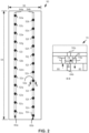
- FIG. 2 provides an example fluid ejection die 50.
- the die 50 includes a plurality of nozzles 52a-x arranged along the die length 54 and the die width 56.
- a nozzle position corresponds to a position along the die length 54
- the die 50 includes a first nozzle 52a at a first nozzle position through a 24th nozzle 52x at a 24th nozzle position.
- the nozzles 52a-x of the example die 50 are arranged such that, for a set of neighboring nozzles (i.e., nozzles having sequential nozzle positions), at least a subset of the set of neighboring nozzles are positioned at different positions along the width of the die 56.
- the first nozzle 52a (at the first nozzle position) and a second nozzle 52b (at the second nozzle position) may be considered a set of neighboring nozzles.
- the first nozzle 52a and the second nozzle 52b are spaced apart with respect to the die width 56 - i.e., the first nozzle 52a and the second nozzle 52b are positioned at different die width positions along the width of the fluid ejection die 50.
- the nozzles 52a-x are arranged in a first nozzle column 60a and a second nozzle column 60b.
- the fluid ejection die 50 further includes an array of ribs 64a, 64b (illustrated in dashed line) formed on a back surface of the die 50. As shown, the array of ribs 64a, 64b are aligned with the nozzle columns 60a, 60b for the example die 50.
- a cross-sectional view 70 along line B-B provides further detail regarding the arrangement of the ribs 64a, 64b and further features of the fluid ejection die 50.
- the fluid ejection die 50 further includes a respective first fluid feed hole 72a and a respective second fluid feed hole 72b fluidically coupled to a respective fluid ejection chamber 74.
- Each respective fluid ejection chamber 74 is further fluidically coupled to the respective nozzle 52p.
- the fluid ejection chamber 74 is arranged over a respective rib 64b of the array of ribs such that the first fluid feedhole 72a is positioned on a first side of the respective rib 64b and the second fluid feedhole 72b is positioned on a second side of the respective rib 64b.
- the array of ribs 64a, 64b may form fluid circulation channels 80, 82 across the die 50. Accordingly, fluid may be input from a respective first fluid circulation channel 80 via the respective first fluid feed hole 72a into the respective fluid ejection chamber 74. Fluid may be output from the respective fluid ejection chamber 74 to a respective second fluid circulation channel 82 via the respective second fluid feed hole 72b.
- This example flow of fluid which may be referred to as microrecirculation is illustrated in FIG. 2 in dashed line. While not shown, it may be appreciated that, fluid may also be output from the respective fluid ejection chamber as fluid drops via the respective nozzle 52p.
- the die 50 may further comprise a respective first fluid actuator 90 disposed in the respective fluid ejection chamber 74. Actuation of the respective first fluid actuator 90 may cause ejection of a drop of fluid from the respective fluid ejection chamber 74.
- the first fluid actuator 90 may be a thermal resistor based fluid actuator, which may be referred to as a thermal fluid actuator.
- the die 50 may further include a respective second fluid actuator 92. Actuation of the respective second fluid actuator 92 may cause flow of fluid from the respective fluid ejection chamber 74 into the respective second fluid circulation channel 82. Accordingly, while the nozzles 52a-x may be fluidically coupled together for a fluid source, the ribs 64a-b may fluidically separate the fluid input to the ejection chambers 74 and the fluid output from the ejection chambers 74.
- the respective first fluid circulation channel 80 may also be fluidically coupled to respective first fluid feed holes for all respective fluid ejection chambers of the die 50.
- the respective first fluid circulation channel 80 may be a fluid input supply for the nozzles 52a-x of the die 50.
- Fluid circulated through the fluid ejection chambers 74 e.g., the example flow illustrated in the cross-sectional view 70
- FIG. 3 provides a block diagram of an example fluid ejection die 100.
- the die 100 comprises a plurality of nozzles 102a-x arranged along a die length 104 and a die width 106.
- the nozzles 102a-x are arranged such that one nozzle 102a-x is positioned at each die length 104 position and neighboring nozzles (e.g., a first nozzle 102a, a second nozzle 102b, a third nozzle 102c; or a fourth nozzle 102d and a fifth nozzle 102e) are positioned at different die width 106 positions.
- the nozzles 102a-x are arranged in four nozzle columns 110a-d.
- the fluid ejection die 100 of FIG. 3 includes an array of ribs 112a, 112b.
- orifices of each nozzle 102a-x may be formed on a front surface of the fluid ejection die 100.
- the array of ribs 112a, 112b may be disposed on an opposite, back surface, of the fluid ejection die 100.
- the array of ribs 112a, 112b may form fluid circulation channels 114, 116a,b through the fluid ejection die 100.
- the fluid ejection die 100 may further include a respective first fluid feed hole 120a-x and a respective second fluid feed hole 122a-x.
- each first fluid feed hole 120a-x may be fluidically coupled to a first fluid circulation channel 114 of the array of fluid circulation channels 114, 116a, b.
- each second fluid feed hole 122a-x may be fluidically coupled to second fluid circulation channels 116a, b.
- the fluid ejection die comprises an array of fluid feed holes 120a-x, 122a-x formed through a surface of the die 100 that is opposite the surface through which the nozzles 102a-x are formed.
- the fluid ejection die 100 comprises two fluid feed holes 120a-x, 122ax for each respective ejection chamber and nozzle 102a-x.
- the array of fluid feed holes 120a-x, 122a-x may be formed through a surface of the die 100 that also engages the ribs 112a-b.
- the nozzles 102a-x may be formed through a top surface of the die 100
- the fluid feed holes 122a-x may be formed through a bottom surface of the die 100 that my be adjacent the ribs 112a-b, and the bottom surface may define an interior surface of the fluid channels 114, 116a-b.
- the fluidic die 100 may include a respective fluid ejection chamber disposed under each respective nozzle 102a-x, and the fluid ejection die 100 may further include at least one respective fluid actuator disposed in each respective fluid ejection chamber.
- each nozzle 102a-x (and the respective fluid ejection chamber disposed thereunder) may be fluidically coupled to the respective first fluid feed hole 120a-x and the respective second fluid feedhole 122a-x by a respective microfluidic channel 128.
- each respective first fluid feed hole 120a-x may be a fluid input, where fresh fluid may be sourced from the first fluid circulation channel 114.
- each respective second fluid feedhole may be a fluid outlet, where fluid may be conveyed to the second fluid circulation channels 116a-b when the fluid is not ejected via the nozzles 102a-x.
- fluid may be input into a respective ejection chamber associated with a respective nozzle 102a-x via the respective first fluid feedhole 120a-x and the respective microfluidic channel 128 from the first fluid circulation channel 114.
- Fluid drops may be ejected from the respective ejection chamber by actuation of at least one fluid actuator disposed in the respective ejection chamber through the respective nozzle 102a-x. Fluid may also be conveyed (i.e., output) from the respective fluid ejection chamber through the microfluidic channel 128 and the respective second fluid feed hole 122a-x to the second fluid circulation channels 116a-b. While not included in this example, similar to the example of FIG. 2 , the fluid ejection die 100 may include at least one fluid actuator disposed in each microfluidic channel 128 that may be actuated to facilitate microrecirculation through each fluid ejection chamber.
- the at least one fluid actuator may be disposed proximate the respective first fluid feedhole to pump fluid into the ejection chamber. In some examples, the at least one fluid actuator may be disposed proximate the respective second fluid feedhole to pump fluid from the ejection chamber.
- Fluids used therein may include solids suspended in liquid carriers. Microrecirculation of such fluids may reduce settling of such solids in the liquid carriers in the fluid ejection chambers.
- a printhead according to may use fluid printing material, such as ink, liquid toner, 3D printer agent, or other such materials.
- the aspects of the fluid circulation channels, array of ribs, and microrecirculation channels may be implemented to facilitate movement of the fluid printing material throughout the fluidic architecture of the printhead to thereby maintain suspension of solids in a liquid carrier of the printing material.
- FIGS. 4A-E provide portions of example fluid ejection dies having various example nozzle arrangements in which nozzles are arranged across and length and the width of the die such that, for each set of neighboring nozzles, a respective subset of each set of neighboring nozzles are positioned at different die width positions along the width of the die. Furthermore, it may be noted that, in these examples, for a respective fluid input, a single nozzle may be positioned at each nozzle position.
- FIG. 4A an example fluid ejection die 200 is illustrated.
- the nozzles 202a-x are arranged along a length and a width of the die.
- the nozzles 202a-x are arranged in eight nozzle columns. 204a-h.
- a first nozzle column 204a may include a first nozzle 202a, a ninth nozzle 2021, and a 17th nozzle 202q.
- the second nozzle column 204b may include a sixth nozzle 202f, a 14th nozzle 202n, and a 22nd nozzle 202v.
- the third nozzle column 204c may include a third nozzle 202c, an 11th nozzle 202k, and a 19th nozzle 202s.
- the fourth nozzle column 204d may include an eighth nozzle 202h, a 16th nozzle 202p, and a 24th nozzle 202x.
- the fifth nozzle column 204e may include a fifth nozzle 202e, a 13th nozzle 202m, and a 21st nozzle 202u.
- the sixth nozzle column 204f may include a second nozzle 202b, a 10th nozzle 202j, and an 18th nozzle 202r.
- the seventh nozzle column 204g may include a seventh nozzle 202g, a 15th nozzle 202o, and 23rd nozzle 202w.
- the eighth nozzle column 204g may include a fourth nozzle 202d, a 12th nozzle 202l, and a 20th nozzle 202t.
- the designation of the first nozzle 202a, second nozzle 202b, etc. refers to the position of the nozzle along the length of the die 200, which may be referred to as the nozzle position.
- the nozzle position As shown in FIG. 4A , at least one nozzle is positioned at each nozzle position along the width of the 200. Accordingly, to perform fluid drop ejection of a fluid for each nozzle position along the width of the die 200, all nozzles 202a-x of this example may be fluidically coupled with the other nozzles 202a-x.
- the nozzle columns 204a-h may be arranged such that a distance between nozzle columns may not be common.
- the first nozzle column 204a and the second nozzle column 204b may be spaced apart by a first distance 206a.
- the second nozzle column 204a and the third nozzle column 204c may be spaced apart by a second distance 206b that is different than the first distance 206a.
- Other nozzle columns 204c-h may be arranged similarly.
- the spacing between the third nozzle column 204c and the fourth nozzle column 204d may be the first distance 206a
- the spacing between the fourth nozzle column and the fifth nozzle column 204e may be the second distance 206b.
- FIG. 4B illustrates an example fluid ejection die 250 having a plurality of nozzles 252a-x arranged along a length and a width of the die 250 in four nozzle columns 254a-d.
- the nozzles 252a-x may be arranged such that some neighboring nozzles may have different angles of orientation therebetween.
- the ninth nozzle 252i and the 10th nozzle 252j may be arranged along the length and width of the die 250 at a first angle of orientation 256.
- the 10th nozzle 252j and the 11th nozzle 252k may be arranged along the length and the width of the die at a second angle of orientation 258 that is different than the first angle of orientation 256.
- FIG. 4C illustrates an example fluid ejection die 270 having a plurality of nozzles 272a-x arranged along a length and a width of the fluid ejection die 270 in two nozzle columns 274a, 274b.
- nozzles 272a-x of a respective nozzle column 274a, 274b may be spaced apart at different distances.
- a first distance 276a between a ninth nozzle 272i and a 10th nozzle 272j of a first nozzle column 274a of the die 270 may be different than a second distance 276b between a second nozzle 272b and a fifth nozzle 272e that are in the first nozzle column 274a.
- Nozzles of a common nozzle column may be referred to as columnar nozzles.
- Nozzles proximate each other in a nozzle column may be referred to as sequential columnar nozzles.
- the first nozzle 272a and the second nozzle 272b may be referred to as sequential columnar nozzles.
- the second nozzle 272b and the fifth nozzle 272e may be considered sequential columnar nozzles.
- the ninth nozzle 272i and the 10th nozzle 272j may be referred to as sequential columnar nozzles.
- the first distance 276a between the sequential columnar nozzles 272i, 272 may be less than 50 ⁇ m
- the second distance 276b between the sequential columnar nozzles 272b, 272e may be at least 100 ⁇ m.
- the first distance may be less than 25 ⁇ m and the second distance 276b may be approximately 100 ⁇ m to approximately 400 ⁇ m.
- angles of orientations between neighboring nozzles may be different for the nozzles 272a-x of the example die 270.
- some neighboring nozzle pairs may be arranged at an angle of orientation that is approximately orthogonal (e.g., the angle of orientation between the first nozzle 272a and the second nozzle 272b).
- Other neighboring nozzle pairs may be arranged at an angle of orientation that is acute (e.g., the angle of orientation between the second nozzle 272b and a third nozzle 272c).
- the fluid ejection die 270 may comprise at least one fluid feed hole 282 for at least two nozzles 272c, 272d. Each nozzle 272c, 272d may be fluidically coupled to a fluid ejection chamber 284a, 284b, and each fluid ejection chamber 284a, 284b may be fluidically coupled to the at least one fluid feed hole 282.
- the die 270 may comprise at least one fluid actuator 286 disposed in each fluid ejection chamber 284a, 284b.
- the example fluid ejection die 300 includes a plurality of nozzles 302a-x arranged along a length and width of the die 300 in two nozzle columns 304a, 304b.
- groups of three neighboring nozzles 302a-x may be sequential columnar nozzles.
- the groups of three neighboring nozzles may be alternately arranged in a respective nozzle column 304a, 304b such that each group of three nozzles 302a-x is spaced apart along the die width from a respective group of nozzles 302a-x corresponding to the next three neighboring nozzles. Accordingly, similar to the example of FIG.
- At least some nozzles 302a-x of a respective nozzle column 304a, 304b may be spaced apart by a first distance (an example of which is indicated with dimension line 306a) and at least some nozzles 302a-x of a respective nozzle column 304a, 304b may be spaced apart by a second distance (an example of which is indicated with dimension line 306b), where the first distance and the second distance may be different.
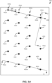
- FIG. 4E illustrates an example fluid ejection die 350 in which a plurality of nozzles 352a-x are arranged along a length and a width of the die 350 in at least three nozzle columns 354a-c. Accordingly, some examples may include at least three staggered nozzle columns.
- an array of ribs 356 are illustrated in dashed line, as the ribs are positioned on an underside of the die 350. As shown, the ribs 356 may be aligned with diagonals along which sets of neighboring nozzles may be arragned.
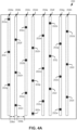
- FIG. 5A this figure provides an example fluid ejection die 400 that includes a plurality of nozzles 402a-x arranged along the die length and the die width in at least four nozzle columns 404a-d.
- a set of neighboring nozzles 402a-x may comprise four nozzles (e.g., a first set of neighboring nozzles may be a first nozzle 402a through a fourth nozzle 402d).
- nozzles within a neighboring nozzle group may be arranged along a diagonal 406 with respect to the length and width of the die.
- An example angle of orientation 408 is provided between the first nozzle 402a and a second nozzle 402b, where the angle of orientation 408 may correspond to the diagonal 406 along which neighboring nozzles may be arranged.
- the diagonal 406 along which neighboring nozzles 402a-x may be arranged may be oblique with respect to the length of the die, and the diagonal 406 may be oblique with respect to the width of the die.
- each set of neighboring nozzles e.g., the first nozzle 402a to the fourth nozzle 402d; a fifth nozzle 402e to an eighth nozzle 402h; etc.
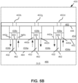
- FIG. 5B provides a cross-sectional view 430 along view line D-D of FIG. 5A
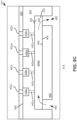
- FIG. 5C provides a cross-sectional view 431 of the example die 400 of FIG. 5A along view line E-E.
- the die 400 includes an array of ribs 432 that define an array of fluid circulation channels 434a-b.
- the cross-sectional view 430 of FIG. 5B includes dashed line depictions of the fourth nozzle 402d, a seventh nozzle 402g, and an 11th nozzle 402k to illustrate the relative positioning of such nozzles 402d, 402g, 402k with respect to the ribs 432 of the array of ribs and the fluid circulation channels 434a-b defined thereby.
- FIG. 5C this figure includes dashed line representations of a 21st nozzle 402u, a 22nd nozzle 402v, a 23rd nozzle 402w, and a 24th nozzle 402x.
- the view line D-D along which the cross-sectional view 430 is presented is approximately orthogonal to the diagonal 406 along which sets of neighboring nozzles may be arranged. Accordingly, other nozzles of the neighboring nozzle sets in which the fourth nozzle 402d, the seventh nozzle 402g, and the 11th nozzle 402k are grouped may be aligned with the depicted nozzles in the cross-sectional view 430. Similarly, it may be appreciated that other nozzles of the first nozzle column 404a, second nozzle column 404b, third nozzle column 404c, and fourth nozzle column 404d may be aligned with the example nozzles 402u-x illustrated in the cross-sectional view 431 of FIG. 5C .
- each respective nozzle 402d, 402g, 402k, 402u-x may be fluidically coupled to a respective fluid ejection chamber 438a-c, 438u-x.
- the die 400 may include, in each fluid ejection chamber 438a-c, 438u-x at least one fluid actuator.
- each respective fluid ejection chamber 438a-c, 438u-x may be fluidically coupled to a respective first fluid feed hole 440a-c
- each respective fluid ejection chamber 438a-c, 438u-x may be fluidically coupled to a respective second fluid feed hole 442a-c, 442u-x.
- the first respective fluid feed hole is not shown, as the cross-sectional view line is positioned such that the first respective fluid feed hole is not included.
- the respective second fluid feed hole 442u-x for a respective ejection chamber 438u-x is illustrated in dashed line because it may be spaced apart from the view line.
- a top surface 450 of each rib 432 of the array of ribs may be adjacent to and engage with a bottom surface 452 of a substrate 454 in which the fluid ejection chambers and fluid feed holes may be at least partially formed.
- the bottom surface 452 of the substrate may form an interior surface of the fluid circulation channels 434a-b.
- the bottom surface 452 of the substrate may be opposite a top surface 456 of the substrate 454, where the top surface 456 of the substrate 454 may be adjacent a nozzle layer 460 in which the nozzles 402d, 402g, 402k may be formed.
- a portion of the fluid ejection chambers 438a-c, 438u-x may be defined by a surface of the nozzle layer 460 disposed above the portion of the fluid ejection chambers 438a-c formed in the substrate 454.
- ejection chambers, nozzles, and feed holes may be formed in more or less layers and substrates.
- a bottom surface 462 of each rib 432 may be adjacent to a top surface 464 of an interposer 466.
- the fluid circulation channels 434a-b may be defined by the fluid circulation ribs 432, the substrate 454, and the interposer 466.
- the fluid ejection die 400 includes an array of fluid feed holes 440a-c, 442a-c, 442u-x formed through the bottom surface 452 of the fluid ejection die 400.
- fluid circulation channels may be arranged to facilitate circulation of fluid through fluid ejection chambers.
- the respective first fluid feedhole 440a-c may be fluidically coupled to a respective first fluid circulation channel 434a such that fluid may be conveyed from the respective first fluid circulation channel 434a to the respective fluid ejection chamber 438a-c, 438u-x via the respective first fluid feed hole 440a-c.
- each respective second fluid feed hole 442a-c, 442u-x may be fluidically coupled to a respective second fluid circulation channel 434b such that fluid may be conveyed from the respective fluid ejection chamber 438a-c, 438u-x to the respective second fluid circulation channel 434b via the respective second fluid feed hole 442a-c, 442u-x.
- the respective first fluid circulation channels 434a and the respective second fluid circulation channels 434b may be fluidly separated by the ribs 432 along some portions of the die 400 such that fluid flow may occur solely through the feed holes 440a-c, 442a-c and the ejection chambers 438a-c.
- the respective first fluid circulation channels 434a may correspond to fluid input channels through which fresh fluid may be input to fluid ejection chambers 438a-c.
- Some fluid input to the ejection chambers 438a-c may be ejected via the nozzles 402d, 402g, 402k as fluid drops.
- some fluid may be conveyed from the ejection chambers 438a-c back to the respective second fluid circulation channels 434b, which may correspond to fluid output channels.
- the ribs 432 of the array of ribs, and the fluid circulation channels 434a-b partially defined thereby may be parallel to the diagonals 406 through which neighboring nozzles 402a-x are also arranged.
- the respective first fluid feed holes of nozzles 402a-x of sets of neighboring nozzles may be commonly coupled to a respective fluid circulation channel 434a
- the respective second fluid feed holes of nozzles 402a-x of sets of neighboring nozzles may be commonly coupled to a respective fluid circulation channel 434b.
- the fluidic arrangement of the ejection chambers 438a-c, the first fluid feed holes 440a-c, and the second fluid feed holes 442a-c may be described as straddling respective ribs 432 of the array of ribs.
- the respective first fluid feed hole 440b coupled to the seventh nozzle 402g and the respective first fluid feed hole 440c coupled to the 11th nozzle 402k are fluidically coupled to a respective first fluid circulation channel 434a.
- the respective second fluid feed hole 442a coupled to the fourth nozzle 402d and the respective second fluid feed hole 442b coupled to the seventh nozzle 402g are fluidically coupled to a respective second fluid circulation channel 434b. Since neighboring nozzles 402a-x are aligned with the nozzles 402d, 402g, 402k shown in FIG. 5B along a respective rib 432, it may be noted that fluid feed holes associated with neighboring nozzles of each respective nozzle shown 402d, 402g, 402k may be similarly arranged.
- ejection chambers 438a-c may be disposed in the substrate above respective ribs 432, and the fluid feed holes 440a-c, 442a-c coupled to a respective fluid ejection chamber 438a-c may be positioned on opposite sides of the respective rib 432 such that fluid input to the respective ejection chamber 438a-c via the respective first fluid feed hole 440a-c may be fluidly separated from fluid output from the respective ejection chamber 438a-c via the respective second fluid feed hole 442a-c.
- the top surface 464 of the interposer 466 may form a surface of the fluid circulation channels 434a-b.
- the interposer 466 may be positioned with respect to the substrate 454 and the ribs 432 such that a die fluid input 480 and a die fluid output 482 may be at least partially defined by the interposer 466 and/or the substrate 454.
- the die fluid input 480 may be fluidically coupled to the fluid circulation channels 434a-b
- the die fluid output 482 may be fluidically coupled to the fluid circulation channels 434a-b.
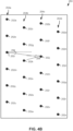
- FIG. 6 provides an illustration of an example fluid ejection die 500 in which a plurality of nozzles is arranged along a length and a width of the fluid ejection die 500.
- the nozzles are arranged into eight nozzle columns 502a-h, which may be referred to as staggered nozzle columns. Accordingly, some examples herein may include at least eight staggered nozzle columns. As may be noted, the nozzles are not labeled in FIG. 6 for clarity.
- FIG. 7 provides an illustration of an example fluid ejection die 550 in which a first plurality of nozzles 552 1 -552 48 and a second plurality of nozzles 554 1 -554 48 are arranged along a length and width of the fluid ejection die 550.
- the first plurality of nozzles 552 1 -552 48 are arranged in a first set of nozzle columns 556a-h, and the second plurality of nozzles 554 1 -554 48 are arranged in a second set of nozzle columns 558a-h. Therefore, some examples may include at least 16 staggered nozzle columns. In some such examples, an example die may include a first set of at least 8 staggered nozzle columns, and a second set of at least 8 staggered nozzle columns.
- the die 550 may include a first array of ribs 560 that define a first array of fluid circulation channels, and the die 550 may further include a second array of ribs 562 that define a second array of fluid circulation channels.
- the arrays of ribs 560, 562 are illustrated in dashed line since the arrays are located under the nozzles 552 1 -552 48 , 554 1 -554 48 and corresponding fluid ejection chambers (not shown).
- the first array of ribs 560 may be disposed proximate a first interposer 570, such that the first interposer forms a surface of the first array of fluid circulation channels.
- the second array of ribs 562 may be disposed proximate a second interposer 572, such that the second interposer 572 forms a surface of the second array of fluid circulation channels.
- the arrangement of the arrays of ribs 560, 562, the fluid circulation channels, and the interposers 570, 572 may be similar to the arrangements of similar elements for the example die 400 shown in FIGS. 5A-C .
- the example of FIG. 7 may include a respective die fluid input and a respective die fluid output defined at least in part by each interposer 570, 572 for each plurality of nozzles 552 1 -552 48 , 554 1 -554 48 .
- the first plurality of nozzles 552 1 -552 48 may be arranged into diagonally arranged neighboring sets of nozzles.
- the first through the eighth nozzle 552 1 -552 8 of the first plurality may be considered a diagonally arranged set of neighboring nozzles.
- the ribs 560 (and the array of fluid circulation channels defined thereby) may be aligned with the diagonally arranged neighboring sets of nozzles.
- the second plurality of nozzles 554 1 -554 48 and ribs of the second array of ribs 562 may be similarly arranged along parallel diagonals with respect to the length and the width of the die 550.
- the first plurality of nozzles 552 1 -552 48 may correspond to a first fluid type
- the second plurality of nozzles 554 1 -554 48 may correspond to a second fluid type.
- the first plurality of fluid nozzles 552 1 -552 48 may correspond to a first colorant (such as a first ink color)
- the second plurality of fluid nozzles 554 1 -554 48 may correspond to a second colorant (such as a second ink color).
- the fluid ejection die 550 of FIG. 7 is in the form of a fluid ejection die implemented in an additive manufacturing system (such as a 3-dimensional printer)
- the first plurality of nozzles 552 1 -552 48 may correspond to a fusing agent
- the second plurality of nozzles 554 1 -554 48 may correspond to a detailing agent. Therefore, as shown and described with respect to this example, the first plurality of nozzles 552 1 -552 48 may be fluidically coupled together, and the second plurality of nozzles 554 1 -554 48 may be fluidically coupled together.
- the first plurality of nozzles 552 1 -552 48 may be fluidically separated from the second plurality of nozzles 554 1 -554 48 .
- the first plurality of nozzles 552 1 -552 48 may be fluidically coupled to the second plurality of nozzles 554 1 -554 48 .
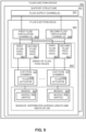
- FIG. 8 provides a block diagram of an example fluid ejection die 600.
- the fluid ejection die includes a plurality of nozzles 602 distributed across a length and width of the fluid ejection die 600 such that at least one respective pair of neighboring nozzles are positioned at different die width positions along the width of the fluid ejection die 600.
- a nozzle 602 may include a nozzle orifice 604 formed on a surface of a layer in which the nozzle 602 is formed through which fluid drops may be ejected.
- the die 600 further includes a plurality of ejection chambers 608 that includes, for each respective nozzle 602, a respective ejection chamber 606 that is fluidically coupled to the nozzle 602.
- the fluid ejection die 600 further comprises at least one fluid actuator 608 disposed in each ejection chamber 606.
- the fluid ejection die 600 further includes an array of fluid feed holes 609 formed on a surface of the die 600 opposite a surface through which the nozzles 602 are formed.
- the array of fluid feed holes 609 of the die 600 includes at least one respective fluid feed hole 610 fluidically coupled to each ejection chamber 606.
- FIG. 9 provides a block diagram of an example fluid ejection device 650.
- the fluid ejection device 650 includes a support structure 652 through which at least one fluid supply channel 653 may be formed.
- the fluid ejection device 650 includes at least one fluid ejection die 654, where the at least one fluid ejection die 654 may include a plurality of nozzles 655 distributed across a length of the die and a width of the die 654, each nozzle 655 includes a nozzle orifice 656 from which fluid drops may be ejected
- the die 654 may include a plurality of ejection chambers 657, where, for each respective nozzle 655, the die 650 includes a respective fluid ejection chamber 657 and at least one fluid actuator 658 disposed therein.
- the fluid ejection die 654 further includes an array of fluid feed holes 659, where the array of fluid feed holes 659 includes a respective first fluid feed hole 660 and a respective second fluid feed hole 662 fluidically coupled to each respective ejection chamber 657.
- Each respective first fluid feed hole 660 may be fluidically coupled to a respective first fluid circulation channel 664
- each respective second fluid feed hole may be fluidically coupled to a respective second fluid circulation channel 668.
- the first fluid circulation channels 664 and the second fluid circulation channels 668 may be fluidically coupled to the at least one fluid circulation channel 653.
- the at least one fluid supply channel 653, the fluid circulation channels 664, 668, the fluid feed holes 660, 662, the ejection chambers 657, and the nozzles 655 may be fluidically coupled together.
- FIG. 10A provides a block diagram illustrates an example layout of a fluid ejection device 700.
- the fluid ejection device 700 comprises a plurality of fluid ejection dies 702a-e arranged along a width 704 of a support structure 706 of the fluid ejection device 700.
- the plurality of fluid ejection dies 702a-e are arranged end-to-end in a staggered manner along the width 706 of the support structure 706.
- a first fluid supply channel 708a and a second fluid supply channel 708b may be formed through the support structure 706 along the width 704 of the support structure 706.
- a first set of fluid ejection dies 702a-c may be arranged generally end-to-end and fluidically coupled to the first fluid supply channel 708a, and a second set of fluid dies 702d-e may be arranged generally end-to-end and fluidically coupled to the second fluid supply channel 708b.
- Detail view 720 of FIG. 10A provides a block diagram that illustrates some components of fluid ejection dies 702a-e of the example fluid ejection device 700.
- the fluid ejection die 702d may include a plurality of nozzles 722 distributed along a length and width of the die 702 such that at least one neighboring nozzle of a respective nozzle of the plurality is spaced apart along the width of the die 702.
- each nozzle 722 is fluidically coupled to a respective ejection chamber 724
- each ejection chamber 724 is fluidically coupled to at least one feed hole 726.
- Each fluid feed hole 726 may be fluidically coupled to a respective fluid circulation channel 728.
- the fluid circulation channels 728 are defined by an array of ribs 730.
- the fluid circulation channels 728 of the example die 702d may be fluidically coupled to the second fluid supply channel 708b. Accordingly, in this example, the nozzles 722 may be fluidically coupled to the second fluid supply channel 708b via the ejection chambers 724, the feed holes 726, and the fluid circulation channels 728.
- FIG. 10B provides a cross-sectional view 750 along view line F-F of FIG. 10A .
- the fluid ejection dies 702c, 702e may be at least partially embedded in the support structure 704.
- a top surface of the fluid ejection dies 702c, 702e may be approximately planar with a top surface of the support structure 706.
- the fluid ejection dies 702c, 702e may be coupled to a surface of the support structure 706.
- each fluid ejection die 702c, 702e comprises nozzles, ejection chambers, and fluid feed holes 722-726 (which are collectively labeled in FIG. 10B for clarity).
- FIG. 10B provides a cross-sectional view 750 along view line F-F of FIG. 10A .
- the fluid ejection dies 702c, 702e may be at least partially embedded in the support structure 704.
- a top surface of the fluid ejection dies 702c, 702e may be approximately planar
- the fluid ejection dies 702c, 702e may be similar to the example fluid ejection die 400 of FIGS. 5A-C . Accordingly, the dies 702 may include an interposer 752 and ribs 730 that define fluid circulation channels 728. As shown, the interposer 752 of each fluid ejection die 702c, 702e at least partially defines a die fluid input 762 and a die fluid output 764 through which fluid may flow from the fluid supply channels 708a-b into the fluid circulation channels 728 of each fluid ejection die 702c, 702e.
- the fluid ejection device 750 may comprise fluid separation members 780 positioned in the fluid supply channels 708a-b.
- the fluid separation members 780 may engage the interposers 752.
- the fluid separation members may fluidically separate the die fluid inputs 762 and the die fluid outputs 764 in the fluid channels 708a-b.
- separation of the fluid channels 708a-b by the fluid separation members 780 may facilitate applying a pressure differential across the die fluid inputs 762, and the die fluid outputs 764, where such pressure differential may generate cross-die fluid circulation through the array of fluid circulation channels 728.
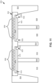
- FIG. 11 provides a cross-sectional view of an example fluid ejection device 800.
- the fluid ejection device 800 includes a fluid ejection die 802 coupled to a support structure 804.
- the fluid ejection die 802 may be similar to the example fluid ejection die 550 of FIG. 7 .
- the fluid ejection die 800 comprises a first plurality of nozzles 806, corresponding ejection chambers, and corresponding fluid feed holes, which are collectively labeled in the example for clarity.
- the die further includes a second plurality of nozzles 810, corresponding ejection chambers, and corresponding fluid feed holes, which are all collectively labeled for clarity.
- the example die 802 further includes a first interposer 810 and a first array of ribs 812 disposed under the first plurality of nozzles 806 such that the first interposer 810 and the first array of ribs 812 form a first array of fluid circulation channels 814.
- the fluid ejection device 800 includes a first fluid supply channel 816 formed through the support structure 804 and fluidically coupled to a first die fluid input 818 and a first die fluid output 820 of the fluid ejection die 802. As shown, the first die fluid input 818 and the first die fluid output 820 are fluidically coupled to the first array of fluid circulation channels 814.
- the example die 800 includes a second interposer 822 and a second array of ribs 824 disposed under the second plurality of nozzles 808 such that the second interposer 822 and the second array of ribs 824 form a second array of fluid circulation channels 826.
- the fluid ejection device 800 includes a second fluid supply channel 828 formed through the support structure 804 and fluidically coupled to a second die fluid input 830 and a second die fluid output 832. As shown, the second die fluid input 830 and the second die fluid output 832 are fluidically coupled to the second array of fluid circulation channels 826.
- the first plurality of nozzles 806 and corresponding fluid components fluidically coupled thereto may be fluidly separated from the second plurality of nozzles 808 and corresponding fluid components fluidically coupled thereto. Accordingly, different types of fluids may be ejected from the first plurality of nozzles 806 and the second plurality of nozzles 808. For example, if the fluid ejection device is in the form of a printhead, the first fluid supply channel 816 may convey a first color of printing material to the first plurality of nozzles 806, and the second fluid supply channel 828 may convey a second color of printing material to the second plurality of nozzles 808.
- an example fluid ejection device may include a plurality of fluid ejection dies similar to the fluid ejection die 802 of FIG. 11 , where the plurality of fluid ejection dies may be arranged generally end-to-end in a staggered manner along a width of a support structure of the fluid ejection device, similar to the example arrangement illustrated in FIG. 10A .
- the fluid ejection device 800 of FIG. 11 includes fluid separation members 840 disposed in the fluid supply channels 816, 828 and engaging the interposers 810, 822.
- the fluid separation members 840 may fluidically separate the die fluid inputs 818, 830 and the die fluid outputs 820, 832 in the fluid supply channels 816, 828.
- fluid flow through the array of fluid circulation channels 814, 826 of the die 802 may be caused by applying a pressure differential between the die fluid inputs 818, 830 and the die fluid outputs 820, 832.
- examples provided herein may provide a fluid ejection die including nozzle arrangements in which at least some nozzles may be distributed along a length and a width of the fluid ejection die. Some examples may include arrangements of nozzles in which nozzle columns may be spaced apart along a width of the fluid ejection die in a staggered manner, similar to the example illustrated in FIG. 1 . In other examples, fluid ejection dies may include nozzle arrangements in which some neighboring nozzles may be aligned in a respective nozzle column, while other neighboring nozzles may be spaced apart such that the other neighboring nozzles are in at least one different nozzle column, similar to the examples shown in FIGS. 4C and 4D . Other examples may include various combinations of example nozzle arrangements described herein.
- some example fluid ejection dies contemplated hereby may include at least 40 nozzles per nozzle column. In some examples, fluid ejection dies may include at least 100 nozzles per nozzle column. In still other examples, some fluid ejection dies may include at least 200 nozzles per column. In some examples, each nozzle column may include less than 400 nozzles per nozzle column. In some examples, each nozzle column may include less than 250 nozzles per nozzle column. Similarly, some examples may include more than 500 nozzles on an example fluid ejection die.
- Some examples may include at least than 1000 nozzles on an example fluid ejection die. Some examples may include at least 1200 nozzles on a fluid ejection die. In some examples, the fluid ejection die may include at least 2400 nozzles. In some examples, the fluid ejection die may include less than 2400 nozzles.
- nozzles as described herein may be according to some dimensional relationships such that aerodynamic effects caused due to fluid drop ejection may be reduced and/or controlled.
- at least one pair of neighboring nozzles may be spaced apart along a width of the fluid ejection die by at least approximately 50 ⁇ m.
- at least one neighboring nozzle pair may be spaced apart along a width of the fluid ejection die by at least 100 ⁇ m.
- a respective distance along a width of a fluid ejection die between two respective nozzles of a respective neighboring nozzle pair may be within a range of approximately 100 ⁇ m and 1200 ⁇ m.
- a respective distance along a length of a fluid ejection die between at least two sequential nozzles of a respective nozzle column may be at least approximately 50 ⁇ m. In some examples, a respective distance along a length of a fluid ejection die between at least two sequential nozzles of a respective nozzle column may be at least approximately 100 ⁇ m. In some examples, a respective distance along a length of a fluid ejection die between at least two sequential nozzles of a respective nozzle column may be within a range of approximately 100 ⁇ m to approximately 400 ⁇ m. In some examples, such distances between nozzles may be different between different neighboring nozzle pairs and/or sequential nozzles of a respective column.
- fluid ejection dies may include more nozzle columns or less nozzle columns than the examples described herein.
- at least three nozzle columns may be fluidically coupled together such that nozzles of such nozzle columns may eject drops of a particular fluid.
- some fluid ejection dies may include at least four nozzle columns spaced apart along the width of the die, where the nozzles may be fluidically coupled such that nozzles of the nozzle columns may eject drops of a particular fluid.
- Some examples contemplated hereby may include at least 16 nozzle columns fluidically coupled such that a particular fluid may be ejected by nozzles of the 16 nozzle columns.
- a nozzle column to nozzle column distance may be at least 100 ⁇ m. In some examples, a nozzle column to nozzle column distance may be at least 200 ⁇ m. In some examples, a nozzle column to nozzle column distance may be in a range of approximately 200 ⁇ m to approximately 1200 ⁇ m.
- each nozzle column may include approximately 50 nozzles to approximately 200 nozzles per inch of length of a die. In some examples, each nozzle column may include less than 250 nozzles per inch of length of a die. In some examples contemplated herein, a nozzle-to-nozzle spacing of sequential columnar nozzles may be greater than a nozzle column to nozzle column spacing. In other examples, a nozzle-to-nozzle spacing of sequential columnar nozzles may be less than a nozzle column to nozzle column spacing.
Description
- Fluid ejection dies may eject fluid drops via nozzles thereof. Such fluid ejection dies may include fluid actuators that may be actuated to thereby cause ejection of drops of fluid through nozzle orifices of the nozzles. Some example fluid ejection dies may be printheads, where the fluid ejected may correspond to ink.
-
Patent document US2014/043404 describes a fluid ejection apparatus including a fluid distribution layer between a fluid manifold anda substrate. -
-
FIG. 1 is a schematic view that illustrates some components of an example fluid ejection die. -
FIG. 2 is a schematic view that illustrates some components of an example fluid ejection die. -
FIG. 3 is a schematic view that illustrates some components of an example fluid ejection die. -
FIGS. 4A-E are schematic views that illustrate some components of an example fluid ejection die. -
FIGS. 5A-C are schematic views that illustrate some components of an example fluid ejection die. -
FIG. 6 is a schematic view that illustrates some components of an example fluid ejection die. -
FIG. 7 is a schematic view that illustrates some components of an example fluid ejection die. -
FIG. 8 is a block diagram that illustrates some components of an example fluid ejection die. -
FIG. 9 is a block diagram that illustrates some components of an example fluid ejection device. - F
IGS. 10A-B are block diagrams that illustrate some components of an example fluid ejection die. -
FIG. 11 is a schematic view that illustrates some components of an example fluid ejection device. - Throughout the drawings, identical reference numbers designate similar, but not necessarily identical, elements. The figures are not necessarily to scale, and the size of some parts may be exaggerated to more clearly illustrate the example shown. Moreover, the drawings provide examples and/or implementations consistent with the description; however, the description is not limited to the examples and/or implementations provided in the drawings.
- Examples of fluid ejection dies may comprise nozzles that may be distributed across a length and width of the die. In an example fluid ejection die, each nozzle may be fluidically coupled to an ejection chamber, and a fluid actuator may be disposed in the ejection chamber. Examples may include at least one fluid feed hole fluidically coupled to each ejection chamber and nozzle. Fluid may be conveyed through the at least one fluid feed hole to the ejection chamber for ejection via the nozzle. Description provided herein may describe examples as having nozzles, ejection chambers, fluid feed holes, fluid supply channels, and/or other such fluidic structures. Such fluidic structures may be formed by removing material from a substrate or other material layers.
- Examples provided herein may be formed by performing various microfabrication and/or micromachining processes on a substrate and layers of material to form and/or connect structures and/or components. The substrate may comprise a silicon based wafer or other such similar materials used for microfabricated devices (e.g., glass, gallium arsenide, plastics, etc.). Examples may comprise microfluidic channels, fluid feed holes, fluid actuators, and/or volumetric chambers. Microfluidic channels, holes, and/or chambers may be formed by performing etching, microfabrication processes (e.g., photolithography), or micromachining processes in a substrate. Accordingly, microfluidic channels, feed holes, and/or chambers may be defined by surfaces fabricated in the substrate of a microfluidic device.
- Moreover, material layers may be formed on substrate layers, and microfabrication and/or micromachining processes may be performed thereon to form fluid structures and/or components. An example of a material layers may include, for example, a photoresist layer, in which openings, such as nozzles may be formed. In addition, various structures and corresponding volumes defined thereby may be formed from substrate bonding or other similar processes.
- In example fluid ejection dies, nozzles may be arranged across a length of a fluid ejection die and across a width of the fluid ejection die. In examples described herein a set of neighboring nozzles may refer to at least two nozzles having proximate positions along the die length. In addition, a respective pair of neighboring nozzles and a neighboring nozzle pair may also refer to two nozzles having proximate positions along the die length. In examples contemplated herein, at least one respective pair of neighboring nozzles of a fluid ejection die may be positioned at different positions along the width of the fluid ejection die. Accordingly, at least some nozzles having sequential nozzle positions (which corresponds to the position of the nozzle with respect to the length of the die) may be spaced apart along the width of the fluid ejection die.
- Furthermore, fluid ejection dies described herein may comprise arrangements of nozzles such that the fluid ejection die comprises approximately 2000 to approximately 6000 nozzles on the die. In some examples all nozzles of the die may be coupled to a single fluid source. For example, in an example fluid ejection die in the form of a printhead according to the description provided herein, the printhead may comprise more than 2000 nozzles, where all the nozzles of the die may correspond to a single printing fluid, such as a single ink color. In other examples, a first set of nozzles of a die may be coupled to a first fluid source, and a second set of nozzles of a die may be coupled to a second fluid source. For example, in a printhead, the die may comprise at least 2000 nozzles coupled to a first ink color fluid source, and the die may comprise at least 2000 nozzles coupled to a second ink color fluid source. In these examples, nozzles of the die may be arranged in a distributed manner across a length and a width of the die. For example, nozzles of the die may be arranged such that a minimum distance between nozzles of the die is approximately 100 micrometers (µm).
- As described above, for each nozzle, the fluid ejection die may include a fluid ejector, where the fluid ejector may include a piezoelectric membrane based actuator, a thermal resistor based actuator, an electrostatic membrane actuator, a mechanical/impact driven membrane actuator, a magneto-strictive drive actuator, or other such elements that may cause displacement of fluid responsive to electrical actuation.
- In some fluid ejection dies, ejection of fluid drops from arrangements of nozzles can relate to air flow patterns in a drop ejection area. Some arrangements of nozzles may result in air flow patterns that influence travel of ejected drops in a drop ejection area. Some air flow patterns generated by fluid drop ejection of fluid ejection dies may result in reduced drop trajectory and/or drop placement accuracy. Furthermore, some air flow patterns generated by fluid drop ejection of fluid ejection dies may disperse particles in a drop ejection area that may collect on fluid ejection dies. Accordingly, example fluid ejection dies described herein may distribute nozzles across the length and the width of the die to control air flow patterns. Some examples described herein may reduce air flow generation related to fluid drop ejection based at least in part on nozzle arrangements of the fluid ejection die. Some example fluid ejection dies may reduce air disturbance of ejected fluid drops due to ejection of other fluid drops from proximate nozzles based at least in part on nozzle arrangements described herein. Nozzle arrangements described herein may correspond to distances between nozzles, distances between nozzle columns, angles of orientations between nozzles, densities of nozzles per square unit of surface area of a fluid ejection die, number of nozzles per unit of distance corresponding to a length of a die, or any combination thereof.
- Turning now to the figures, and particularly to
FIG. 1 , this figure illustrates an example fluid ejection die 10. As shown, the fluid ejection die 10 may comprise a plurality ofnozzles 12a-x arranged along a dielength 14 and adie width 16. As used herein, neighboring nozzles may be used to describerespective nozzles 12a-x having proximate positions along the length of the die 14. For example, afirst nozzle 12a, which may be described as having a first nozzle position, may be a neighboring nozzle of asecond nozzle 12b, which may be described as having a second nozzle position. Thefirst nozzle 12a and thesecond nozzle 12b may further be described as a neighboring nozzle pair or a pair of neighboring nozzles. In the example die 10 ofFIG. 1 , the nozzles 12ax may be described as corresponding to a respective nozzle position based on the positioning of thenozzle 12a with respect to the length of thedie 14. Accordingly, in this example, thedie 10 includes thefirst nozzle 12a in a first nozzle position, thesecond nozzle 12b in a second nozzle position, with likewise nozzle location designations for third through 24th nozzle positions 12c-12x respectively. - In addition, in this example, sets of neighboring nozzles and neighboring nozzle sets may be used to refer to groups of nozzles having proximate locations along the
length 14 of the die 10, i.e., sets of neighboring nozzles may include at least twonozzles 12a-x having sequential nozzle positions. For example, thefirst nozzle 12a, thesecond nozzle 12b, and thethird nozzle 12c may be considered a set of neighboring nozzles. Similarly, thefirst nozzle 12a, thesecond nozzle 12b, thethird nozzle 12c, and thefourth nozzle 12d may be considered a set of neighboring nozzles. - Accordingly, in the example of
FIG. 1 , thenozzles 12a-x include at least one respective pair of neighboring nozzles that are positioned at different die width positions along the width of the fluid ejection die. To illustrate by way of example, thefirst nozzle 12a andsecond nozzle 12b are a respective pair of neighboring nozzles, and thefirst nozzle 12a andsecond nozzle 12b are positioned at different positions along thewidth 16 of the die. Similarly, thesecond nozzle 12b and thethird nozzle 12c are a respective pair of neighboring nozzles, and thesecond nozzle 12b and thethird nozzle 12c are positioned at different die width positions along thewidth 16 of the die. Moreover, in this example, thefirst nozzle 12a, thesecond nozzle 12b, thethird nozzle 12c, and afourth nozzle 12d are a set of neighboring nozzles, and at least one nozzle of the respective set of neighboringnozzles 12a-d is positioned at adifferent die width 16 position. Notably, in this example, eachnozzle 12a-d of the respective set of neighboringnozzles 12a-d is positioned at adifferent die width 16 position. Therefore, as shown inFIG. 1 , thenozzles 12a-x of the fluid ejection die 10 are arranged such that, for pairs and sets of neighboring nozzles, at least one respective nozzle of each set of neighboring nozzles is positioned atdifferent die width 16 positions. - Furthermore, it will be noted that the fluid ejection die 10 example of
FIG. 1 includes at least onenozzle 12a-x per nozzle position. Accordingly, it may be appreciated that thenozzles 12a-x of the fluid ejection die may be fluidically coupled to a single fluid source. For example, if the fluid ejection die 10 corresponds to a printhead, thenozzles 12a-x may all couple to a single fluid print material source of a single color. As another example, if the fluid ejection die 10 corresponds to a printhead for an additive manufacturing system, thenozzles 12a-x may be fluidically coupled to a single 3D print material source, such as a fluid bonding agent, a fluid detailing agent, a fluid surface treatment material, etc. Nozzles coupled to a single fluid source may be described as being fluidically coupled together. - In the example shown in
FIG. 1 , the fluid ejection die 10 includes thenozzles 12a-x arranged innozzle columns 20a-d. As shown, afirst nozzle column 20a of the example includes thefirst nozzle 12a, thefifth nozzle 12e, the ninth nozzle 12i, the13th nozzle 12m, the17th nozzle 12q, and the21st nozzle 12u. Asecond nozzle column 20b of the example includes thesecond nozzle 12b, thesixth nozzle 12f, the 10th nozzle 12j, the14th nozzle 12n, the18th nozzle 12r, and the22nd nozzle 12v. Athird nozzle column 20c of the example includes thethird nozzle 12c, the seventh nozzle 12g, the11th nozzle 12k, the 15th nozzle 12o, the19th nozzle 12s, and the23rd nozzle 12w. Afourth nozzle column 20d of the example includes thefourth nozzle 12d, theeighth nozzle 12h, the12th nozzle 121, the16th nozzle 12p, the20th nozzle 12t, and the24th nozzle 12x. - As shown, neighboring nozzles are distributed across the width of the die 16 in
different nozzle columns 20a-d. Moreover, thenozzles 12a-x of eachnozzle column 20a-d are offset along thedie length 14 and thedie width 16, such that respective nozzles of eachnozzle column 20a-d have an oblique angle of orientation with neighboringnozzles 12a-x. An example angle oforientation 22 between neighboring nozzles is illustrated between thesixth nozzle 12f and the seventh nozzle 12g inFIG. 1 . Accordingly, neighboring nozzles located in thedifferent nozzle columns 20a-d may be arranged along a diagonal 24 with respect to thedie length 14 and thedie width 16. As may be noted, the diagonal 24 may correspond to the angle oforientation 22 between neighboring nozzles. Furthermore, it may be noted that in some examples, a size of a set of neighboring nozzles may correspond to the number of nozzle columns. In the example ofFIG. 1 , the size of the set of neighboring nozzles may be four nozzles, and the number ofnozzle columns 20a-d may also be four. Accordingly, for a set of four neighboring nozzles, each respective nozzle of the set may be arranged in a differentrespective nozzle column 20a-d. - Furthermore, the example of
FIG. 1 illustrates example arrangements of thenozzles 12a-x that may be implemented in other examples. As shown inFIG. 1 ,nozzles 12a-x of arespective nozzle column 20a-d may be arranged such that a nozzle-to-nozzle distance between at least somenozzles 12a-x of therespective nozzle column 20a-d may be at least 100 micrometers (µm). In some examples, a nozzle-to-nozzle distance 24 for at least some nozzles of arespective nozzle column 20a-d may be within a range of approximately 100 µm to approximately 400 µm. In the example ofFIG. 1 ,proximate nozzles 12a-x of arespective nozzle column 20a-d may be referred to assequential nozzles 12a-x of therespective nozzle column 20a-d. To illustrate by way of example, thefirst nozzle 12a and thefifth nozzle 12e may be referred to as sequential nozzles of the respectivefirst nozzle column 20a. Similarly, thesecond nozzle 12b and thesixth nozzle 12f may be referred to as sequential nozzles of the respectivesecond nozzle column 20b. Therefore, the nozzle-to-nozzle distance 24 fornozzles 12a-x of arespective column 20a-d may refer to the distance betweensequential nozzles 12a-x of therespective column 20a-d. - Likewise, the example of
FIG. 1 also illustrates an arrangement of nozzle columns that may be implemented in other examples. As shown, a distance between nozzle columns 26 (which may be referred to as a nozzle column to nozzle column distance) may be at least approximately 100 µm. In some examples, the distance betweennozzle columns 26 may be within a range of approximately 100 µm to approximately 400 µm. - In
FIG. 1 , a crosssectional view 30 along line A-A is provided. As shown in this example, for each respective nozzle (the examplecross-sectional view 30 is provided for the16th nozzle 12p), the fluid ejection die 10 further includes afluid ejection chamber 32 arranged proximate to and fluidically coupled with thenozzle 12p. The die 10 further includes at least onefluid feed hole 34 fluidically coupled to thefluid ejection chamber 32. Accordingly, in examples contemplated herein, fluid may flow through thefluid feed hole 34 to thefluid ejection chamber 32, and fluid may be ejected from thefluid ejection chamber 32 through thenozzle 12p. As illustrated by thecross-sectional view 30, the fluid ejection die 10 may comprise an array of fluid feed holes 34 formed through a surface opposite the surface through which thenozzle 12p is formed. - As may be appreciated with respect to
FIG. 1 , the quantity of nozzles shown is for clarity. Examples of fluid ejection dies may comprise more nozzles in more or less nozzle columns. In some example fluid ejection dies, the die may comprise approximately 2000 to approximately 6000 nozzles. In addition, some example nozzle columns of such example fluid ejection dies may comprise at approximately 40 to approximately 300 nozzles per column. - Furthermore, in some examples spacing between nozzles of a respective nozzle column (e.g., the distance between the
first nozzle 12a and thefifth nozzle 12e ofFIG. 1 ) may be approximately 50µm to approximately 500µm. In other examples, the spacing between nozzles of a respective nozzle column may be at least 100µm. Similarly, in some examples a spacing between nozzle columns (e.g., the distance between thefirst nozzle column 20a and thesecond nozzle column 20b inFIG. 1 ) may be approximately 50µm to approximately 500µm. In some examples, the spacing between nozzle columns may be at least 100µm. - Moreover, as shown in
FIG. 1 , nozzle columns may be arranged in an offset manner such that, for a set of nozzle columns, at least one nozzle is located at each respective nozzle position (where the nozzle position corresponds to a position along the length of the die). Therefore, it will be appreciated that, in such examples, the angle of orientation (e.g., the angle oforientation 22 shown inFIG. 1 ) between neighboring nozzles may be such that nozzles of different nozzle columns are arranged in unique nozzle positions. In other words, the diagonal arrangement of nozzles across the length and width of the die are such that nozzles of different nozzle columns are neighboring nozzles and nozzles of different nozzle columns are not positioned at common nozzle positions. In some examples, an angle of orientation between neighboring nozzles may be approximately 10° to approximately 45°. In some examples, an angle of orientation between neighboring nozzles may be at least 20°. In other examples, an angle of orientation may be less than approximately 75°. Furthermore, nozzles of a respective nozzle column may be offset with regard to the width of the die to adjust for drop ejection timing. Accordingly, while examples illustrated herein may illustrate aligned diagonals and columns of nozzles, other examples may include columnar nozzles having offsets along the width of the die. In some examples, nozzles of a respective column may be offset with respect along the width by approximately 5 µm to approximately 30 µm. - Accordingly, the spacing between nozzles, the spacing between nozzle columns, and the angle of orientation between neighboring nozzles may be defined such that nozzle columns are arranged in a staggered and offset manner across the die. In such examples, the spacing between nozzles, the spacing between nozzle columns, and/or the angle of orientation between neighboring nozzles may facilitate ejection of fluid drops via such nozzles that controls generated air flow associated with such ejections.
- In some examples, columns of nozzles may be spaced apart across the width of the die, and the columns of nozzles may be staggered and/or off-set along the length of the die. In some examples, at least some nozzles of different nozzle columns may be staggered according to an angle of orientation. The arrangement of
nozzles 12a-x andnozzle columns 20a-d may be referred to as staggered nozzle columns. Accordingly, examples contemplated herein may include at least four staggered nozzle columns. -
FIG. 2 provides an example fluid ejection die 50. As shown, thedie 50 includes a plurality ofnozzles 52a-x arranged along thedie length 54 and thedie width 56. As discussed previously, a nozzle position corresponds to a position along thedie length 54, and in this example, thedie 50 includes afirst nozzle 52a at a first nozzle position through a24th nozzle 52x at a 24th nozzle position. Thenozzles 52a-x of the example die 50 are arranged such that, for a set of neighboring nozzles (i.e., nozzles having sequential nozzle positions), at least a subset of the set of neighboring nozzles are positioned at different positions along the width of thedie 56. For example, thefirst nozzle 52a (at the first nozzle position) and asecond nozzle 52b (at the second nozzle position) may be considered a set of neighboring nozzles. As shown, thefirst nozzle 52a and thesecond nozzle 52b are spaced apart with respect to the die width 56 - i.e., thefirst nozzle 52a and thesecond nozzle 52b are positioned at different die width positions along the width of the fluid ejection die 50. - In the example die 50 of
FIG. 2 , thenozzles 52a-x are arranged in afirst nozzle column 60a and asecond nozzle column 60b. In this example, the fluid ejection die 50 further includes an array ofribs die 50. As shown, the array ofribs nozzle columns cross-sectional view 70 along line B-B provides further detail regarding the arrangement of theribs respective nozzle 52a-x (in the example cross-sectional view, the16th nozzle 52p is illustrated), the fluid ejection die 50 further includes a respective firstfluid feed hole 72a and a respective secondfluid feed hole 72b fluidically coupled to a respectivefluid ejection chamber 74. Each respectivefluid ejection chamber 74 is further fluidically coupled to therespective nozzle 52p. - As shown, the
fluid ejection chamber 74 is arranged over arespective rib 64b of the array of ribs such that thefirst fluid feedhole 72a is positioned on a first side of therespective rib 64b and thesecond fluid feedhole 72b is positioned on a second side of therespective rib 64b. The array ofribs fluid circulation channels die 50. Accordingly, fluid may be input from a respective firstfluid circulation channel 80 via the respective firstfluid feed hole 72a into the respectivefluid ejection chamber 74. Fluid may be output from the respectivefluid ejection chamber 74 to a respective secondfluid circulation channel 82 via the respective secondfluid feed hole 72b. This example flow of fluid, which may be referred to as microrecirculation is illustrated inFIG. 2 in dashed line. While not shown, it may be appreciated that, fluid may also be output from the respective fluid ejection chamber as fluid drops via therespective nozzle 52p. - As shown in the
cross-sectional view 70 ofFIG. 2 , for eachrespective nozzle 52p, thedie 50 may further comprise a respective firstfluid actuator 90 disposed in the respectivefluid ejection chamber 74. Actuation of the respective firstfluid actuator 90 may cause ejection of a drop of fluid from the respectivefluid ejection chamber 74. In some examples, thefirst fluid actuator 90 may be a thermal resistor based fluid actuator, which may be referred to as a thermal fluid actuator. The die 50 may further include a respective secondfluid actuator 92. Actuation of the respective secondfluid actuator 92 may cause flow of fluid from the respectivefluid ejection chamber 74 into the respective secondfluid circulation channel 82. Accordingly, while thenozzles 52a-x may be fluidically coupled together for a fluid source, theribs 64a-b may fluidically separate the fluid input to theejection chambers 74 and the fluid output from theejection chambers 74. - While not illustrated in the example
cross-sectional view 70, it may be appreciated that the respective firstfluid circulation channel 80, surfaces of which may be defined by thefirst rib 64a andsecond rib 64b of the array of ribs, may also be fluidically coupled to respective first fluid feed holes for all respective fluid ejection chambers of thedie 50. Accordingly, the respective firstfluid circulation channel 80 may be a fluid input supply for thenozzles 52a-x of thedie 50. Fluid circulated through the fluid ejection chambers 74 (e.g., the example flow illustrated in the cross-sectional view 70) may be fluidically separated from the respective firstfluid circulation channel 80, and therefore fluidically separated from the fluid input supply to therespective ejection chambers 74 via thefirst rib 64a and thesecond rib 64b. -
FIG. 3 provides a block diagram of an example fluid ejection die 100. In this example, thedie 100 comprises a plurality ofnozzles 102a-x arranged along adie length 104 and adie width 106. In particular, thenozzles 102a-x are arranged such that onenozzle 102a-x is positioned at eachdie length 104 position and neighboring nozzles (e.g., afirst nozzle 102a, a second nozzle 102b, athird nozzle 102c; or afourth nozzle 102d and afifth nozzle 102e) are positioned atdifferent die width 106 positions. In this example, thenozzles 102a-x are arranged in fournozzle columns 110a-d. - Furthermore, the fluid ejection die 100 of
FIG. 3 includes an array ofribs FIG. 3 , orifices of eachnozzle 102a-x may be formed on a front surface of the fluid ejection die 100. The array ofribs ribs fluid circulation channels nozzle 102a-x, the fluid ejection die 100 may further include a respective firstfluid feed hole 120a-x and a respective secondfluid feed hole 122a-x. In this example, the each firstfluid feed hole 120a-x may be fluidically coupled to a firstfluid circulation channel 114 of the array offluid circulation channels fluid feed hole 122a-x may be fluidically coupled to secondfluid circulation channels 116a, b. Accordingly, in this example, the fluid ejection die comprises an array offluid feed holes 120a-x, 122a-x formed through a surface of the die 100 that is opposite the surface through which thenozzles 102a-x are formed. In this example, the fluid ejection die 100 comprises twofluid feed holes 120a-x, 122ax for each respective ejection chamber andnozzle 102a-x. Moreover, as shown, the array offluid feed holes 120a-x, 122a-x may be formed through a surface of the die 100 that also engages theribs 112a-b. Notably, thenozzles 102a-x may be formed through a top surface of thedie 100, and thefluid feed holes 122a-x may be formed through a bottom surface of the die 100 that my be adjacent theribs 112a-b, and the bottom surface may define an interior surface of thefluid channels - While not shown in this example for clarity, the fluidic die 100 may include a respective fluid ejection chamber disposed under each
respective nozzle 102a-x, and the fluid ejection die 100 may further include at least one respective fluid actuator disposed in each respective fluid ejection chamber. As shown in this example, eachnozzle 102a-x (and the respective fluid ejection chamber disposed thereunder) may be fluidically coupled to the respective firstfluid feed hole 120a-x and the respective second fluid feedhole 122a-x by a respectivemicrofluidic channel 128. - As may be appreciated, in this example, each respective first
fluid feed hole 120a-x may be a fluid input, where fresh fluid may be sourced from the firstfluid circulation channel 114. Likewise, each respective second fluid feedhole may be a fluid outlet, where fluid may be conveyed to the secondfluid circulation channels 116a-b when the fluid is not ejected via thenozzles 102a-x. Accordingly, in some examples, fluid may be input into a respective ejection chamber associated with arespective nozzle 102a-x via the respective first fluid feedhole 120a-x and the respectivemicrofluidic channel 128 from the firstfluid circulation channel 114. Fluid drops may be ejected from the respective ejection chamber by actuation of at least one fluid actuator disposed in the respective ejection chamber through therespective nozzle 102a-x. Fluid may also be conveyed (i.e., output) from the respective fluid ejection chamber through themicrofluidic channel 128 and the respective secondfluid feed hole 122a-x to the secondfluid circulation channels 116a-b. While not included in this example, similar to the example ofFIG. 2 , the fluid ejection die 100 may include at least one fluid actuator disposed in eachmicrofluidic channel 128 that may be actuated to facilitate microrecirculation through each fluid ejection chamber. In some examples, the at least one fluid actuator may be disposed proximate the respective first fluid feedhole to pump fluid into the ejection chamber. In some examples, the at least one fluid actuator may be disposed proximate the respective second fluid feedhole to pump fluid from the ejection chamber. - Conveying fluid from a fluid input through an ejection chamber and to a fluid output may be referred to as microrecirculation. In some example fluid ejection dies and fluid ejection devices similar to the examples described herein, fluids used therein may include solids suspended in liquid carriers. Microrecirculation of such fluids may reduce settling of such solids in the liquid carriers in the fluid ejection chambers. As an example, a printhead according to may use fluid printing material, such as ink, liquid toner, 3D printer agent, or other such materials. In such example printheads, the aspects of the fluid circulation channels, array of ribs, and microrecirculation channels may be implemented to facilitate movement of the fluid printing material throughout the fluidic architecture of the printhead to thereby maintain suspension of solids in a liquid carrier of the printing material.
- Turning now to
FIGS. 4A-E , these figures provide portions of example fluid ejection dies having various example nozzle arrangements in which nozzles are arranged across and length and the width of the die such that, for each set of neighboring nozzles, a respective subset of each set of neighboring nozzles are positioned at different die width positions along the width of the die. Furthermore, it may be noted that, in these examples, for a respective fluid input, a single nozzle may be positioned at each nozzle position. - In
FIG. 4A , an example fluid ejection die 200 is illustrated. As shown, thenozzles 202a-x are arranged along a length and a width of the die. In this example, thenozzles 202a-x are arranged in eight nozzle columns. 204a-h. In this example, afirst nozzle column 204a may include afirst nozzle 202a, aninth nozzle 2021, and a17th nozzle 202q. Thesecond nozzle column 204b may include a sixth nozzle 202f, a14th nozzle 202n, and a22nd nozzle 202v. Thethird nozzle column 204c may include athird nozzle 202c, an11th nozzle 202k, and a19th nozzle 202s. Thefourth nozzle column 204d may include aneighth nozzle 202h, a16th nozzle 202p, and a24th nozzle 202x. Thefifth nozzle column 204e may include afifth nozzle 202e, a13th nozzle 202m, and a21st nozzle 202u. Thesixth nozzle column 204f may include asecond nozzle 202b, a10th nozzle 202j, and an18th nozzle 202r. Theseventh nozzle column 204g may include aseventh nozzle 202g, a 15th nozzle 202o, and23rd nozzle 202w. Theeighth nozzle column 204g may include afourth nozzle 202d, a 12th nozzle 202l, and a 20th nozzle 202t. - In this example, the designation of the
first nozzle 202a,second nozzle 202b, etc. refers to the position of the nozzle along the length of thedie 200, which may be referred to as the nozzle position. Notably, as shown inFIG. 4A , at least one nozzle is positioned at each nozzle position along the width of the 200. Accordingly, to perform fluid drop ejection of a fluid for each nozzle position along the width of thedie 200, allnozzles 202a-x of this example may be fluidically coupled with theother nozzles 202a-x. - In addition, in this example, the
nozzle columns 204a-h may be arranged such that a distance between nozzle columns may not be common. As shown, thefirst nozzle column 204a and thesecond nozzle column 204b may be spaced apart by afirst distance 206a. Thesecond nozzle column 204a and thethird nozzle column 204c may be spaced apart by asecond distance 206b that is different than thefirst distance 206a.Other nozzle columns 204c-h may be arranged similarly. For example, the spacing between thethird nozzle column 204c and thefourth nozzle column 204d may be thefirst distance 206a, and the spacing between the fourth nozzle column and thefifth nozzle column 204e may be thesecond distance 206b. -
FIG. 4B illustrates an example fluid ejection die 250 having a plurality ofnozzles 252a-x arranged along a length and a width of the die 250 in fournozzle columns 254a-d. Furthermore, inFIG. 4B , it may be noted that thenozzles 252a-x may be arranged such that some neighboring nozzles may have different angles of orientation therebetween. For example, referring to aninth nozzle 252i, a10th nozzle 252j, and an11th nozzle 252k of the example, as shown, theninth nozzle 252i and the10th nozzle 252j may be arranged along the length and width of the die 250 at a first angle oforientation 256. And the10th nozzle 252j and the11th nozzle 252k may be arranged along the length and the width of the die at a second angle oforientation 258 that is different than the first angle oforientation 256. -
FIG. 4C illustrates an example fluid ejection die 270 having a plurality ofnozzles 272a-x arranged along a length and a width of the fluid ejection die 270 in twonozzle columns FIG. 4C , in some examples,nozzles 272a-x of arespective nozzle column FIG. 4C , afirst distance 276a between a ninth nozzle 272i and a10th nozzle 272j of afirst nozzle column 274a of thedie 270 may be different than asecond distance 276b between asecond nozzle 272b and afifth nozzle 272e that are in thefirst nozzle column 274a. Nozzles of a common nozzle column may be referred to as columnar nozzles. Nozzles proximate each other in a nozzle column may be referred to as sequential columnar nozzles. For example, thefirst nozzle 272a and thesecond nozzle 272b may be referred to as sequential columnar nozzles. Similarly, thesecond nozzle 272b and thefifth nozzle 272e may be considered sequential columnar nozzles. Furthermore, the ninth nozzle 272i and the10th nozzle 272j may be referred to as sequential columnar nozzles. Returning to the example above, thefirst distance 276a between the sequential columnar nozzles 272i, 272 may be less than 50 µm, and thesecond distance 276b between the sequentialcolumnar nozzles second distance 276b may be approximately 100 µm to approximately 400 µm. Furthermore, while not labeled inFIG. 4C , it may be noted that angles of orientations between neighboring nozzles may be different for thenozzles 272a-x of the example die 270. For example, some neighboring nozzle pairs may be arranged at an angle of orientation that is approximately orthogonal (e.g., the angle of orientation between thefirst nozzle 272a and thesecond nozzle 272b). Other neighboring nozzle pairs may be arranged at an angle of orientation that is acute (e.g., the angle of orientation between thesecond nozzle 272b and athird nozzle 272c). - A
cross-sectional view 280 along line C-C is provided inFIG. 4C . As shown, the fluid ejection die 270 may comprise at least onefluid feed hole 282 for at least twonozzles nozzle fluid ejection chamber fluid ejection chamber fluid feed hole 282. In addition, similar to other examples, thedie 270 may comprise at least onefluid actuator 286 disposed in eachfluid ejection chamber - In
FIG. 4D , the example fluid ejection die 300 includes a plurality ofnozzles 302a-x arranged along a length and width of the die 300 in twonozzle columns nozzles 302a-x may be sequential columnar nozzles. The groups of three neighboring nozzles may be alternately arranged in arespective nozzle column nozzles 302a-x is spaced apart along the die width from a respective group ofnozzles 302a-x corresponding to the next three neighboring nozzles. Accordingly, similar to the example ofFIG. 4C , at least somenozzles 302a-x of arespective nozzle column dimension line 306a) and at least somenozzles 302a-x of arespective nozzle column dimension line 306b), where the first distance and the second distance may be different. -
FIG. 4E illustrates an example fluid ejection die 350 in which a plurality ofnozzles 352a-x are arranged along a length and a width of the die 350 in at least threenozzle columns 354a-c. Accordingly, some examples may include at least three staggered nozzle columns. In this example, an array ofribs 356 are illustrated in dashed line, as the ribs are positioned on an underside of thedie 350. As shown, theribs 356 may be aligned with diagonals along which sets of neighboring nozzles may be arragned. - Turning now to
FIG. 5A , this figure provides an example fluid ejection die 400 that includes a plurality ofnozzles 402a-x arranged along the die length and the die width in at least fournozzle columns 404a-d. In this example, a set of neighboringnozzles 402a-x may comprise four nozzles (e.g., a first set of neighboring nozzles may be afirst nozzle 402a through afourth nozzle 402d). Furthermore, nozzles within a neighboring nozzle group may be arranged along a diagonal 406 with respect to the length and width of the die. An example angle oforientation 408 is provided between thefirst nozzle 402a and asecond nozzle 402b, where the angle oforientation 408 may correspond to the diagonal 406 along which neighboring nozzles may be arranged. In some examples, the diagonal 406 along which neighboringnozzles 402a-x may be arranged may be oblique with respect to the length of the die, and the diagonal 406 may be oblique with respect to the width of the die. In examples similar to the example die 400, each set of neighboring nozzles (e.g., thefirst nozzle 402a to thefourth nozzle 402d; afifth nozzle 402e to aneighth nozzle 402h; etc.) may be arranged along parallel diagonals. -
FIG. 5B provides across-sectional view 430 along view line D-D ofFIG. 5A , andFIG. 5C provides across-sectional view 431 of the example die 400 ofFIG. 5A along view line E-E. In this example, thedie 400 includes an array ofribs 432 that define an array offluid circulation channels 434a-b. Furthermore, thecross-sectional view 430 ofFIG. 5B includes dashed line depictions of thefourth nozzle 402d, aseventh nozzle 402g, and an11th nozzle 402k to illustrate the relative positioning ofsuch nozzles ribs 432 of the array of ribs and thefluid circulation channels 434a-b defined thereby. Referring toFIG. 5C , this figure includes dashed line representations of a21st nozzle 402u, a22nd nozzle 402v, a23rd nozzle 402w, and a24th nozzle 402x. - Furthermore, it may be appreciated that the view line D-D along which the
cross-sectional view 430 is presented is approximately orthogonal to the diagonal 406 along which sets of neighboring nozzles may be arranged. Accordingly, other nozzles of the neighboring nozzle sets in which thefourth nozzle 402d, theseventh nozzle 402g, and the11th nozzle 402k are grouped may be aligned with the depicted nozzles in thecross-sectional view 430. Similarly, it may be appreciated that other nozzles of thefirst nozzle column 404a,second nozzle column 404b,third nozzle column 404c, andfourth nozzle column 404d may be aligned with theexample nozzles 402u-x illustrated in thecross-sectional view 431 ofFIG. 5C . - In addition, as shown in dashed line, each
respective nozzle fluid ejection chamber 438a-c, 438u-x. While not shown, thedie 400 may include, in eachfluid ejection chamber 438a-c, 438u-x at least one fluid actuator. Furthermore, each respectivefluid ejection chamber 438a-c, 438u-x may be fluidically coupled to a respective firstfluid feed hole 440a-c, and each respectivefluid ejection chamber 438a-c, 438u-x may be fluidically coupled to a respective secondfluid feed hole 442a-c, 442u-x. In thecross-sectional view 431 ofFIG. 5C , the first respective fluid feed hole is not shown, as the cross-sectional view line is positioned such that the first respective fluid feed hole is not included. The respective secondfluid feed hole 442u-x for arespective ejection chamber 438u-x is illustrated in dashed line because it may be spaced apart from the view line. - In this example, a
top surface 450 of eachrib 432 of the array of ribs may be adjacent to and engage with abottom surface 452 of asubstrate 454 in which the fluid ejection chambers and fluid feed holes may be at least partially formed. Accordingly, thebottom surface 452 of the substrate may form an interior surface of thefluid circulation channels 434a-b. As shown inFIG. 5B , thebottom surface 452 of the substrate may be opposite atop surface 456 of thesubstrate 454, where thetop surface 456 of thesubstrate 454 may be adjacent anozzle layer 460 in which thenozzles fluid ejection chambers 438a-c, 438u-x may be defined by a surface of thenozzle layer 460 disposed above the portion of thefluid ejection chambers 438a-c formed in thesubstrate 454. In other examples, ejection chambers, nozzles, and feed holes may be formed in more or less layers and substrates. Abottom surface 462 of eachrib 432 may be adjacent to atop surface 464 of aninterposer 466. Accordingly, in this example, thefluid circulation channels 434a-b may be defined by thefluid circulation ribs 432, thesubstrate 454, and theinterposer 466. Accordingly, as shownFIGS. 5B-5C , the fluid ejection die 400 includes an array offluid feed holes 440a-c, 442a-c, 442u-x formed through thebottom surface 452 of the fluid ejection die 400. - In examples similar to the example of
FIGS. 5A-C , fluid circulation channels may be arranged to facilitate circulation of fluid through fluid ejection chambers. In the example, the respective first fluid feedhole 440a-c may be fluidically coupled to a respective firstfluid circulation channel 434a such that fluid may be conveyed from the respective firstfluid circulation channel 434a to the respectivefluid ejection chamber 438a-c, 438u-x via the respective firstfluid feed hole 440a-c. Similarly, each respective secondfluid feed hole 442a-c, 442u-x may be fluidically coupled to a respective secondfluid circulation channel 434b such that fluid may be conveyed from the respectivefluid ejection chamber 438a-c, 438u-x to the respective secondfluid circulation channel 434b via the respective secondfluid feed hole 442a-c, 442u-x. The respective firstfluid circulation channels 434a and the respective secondfluid circulation channels 434b may be fluidly separated by theribs 432 along some portions of the die 400 such that fluid flow may occur solely through thefeed holes 440a-c, 442a-c and theejection chambers 438a-c. - Accordingly, the respective first
fluid circulation channels 434a may correspond to fluid input channels through which fresh fluid may be input tofluid ejection chambers 438a-c. Some fluid input to theejection chambers 438a-c may be ejected via thenozzles ejection chambers 438a-c, some fluid may be conveyed from theejection chambers 438a-c back to the respective secondfluid circulation channels 434b, which may correspond to fluid output channels. - Referring to
FIGS. 5A and5B , it should be noted that theribs 432 of the array of ribs, and thefluid circulation channels 434a-b partially defined thereby may be parallel to thediagonals 406 through which neighboringnozzles 402a-x are also arranged. Furthermore, as shown, in this example, the respective first fluid feed holes ofnozzles 402a-x of sets of neighboring nozzles may be commonly coupled to a respectivefluid circulation channel 434a, and the respective second fluid feed holes ofnozzles 402a-x of sets of neighboring nozzles may be commonly coupled to a respectivefluid circulation channel 434b. In this example, the fluidic arrangement of theejection chambers 438a-c, the firstfluid feed holes 440a-c, and the secondfluid feed holes 442a-c may be described as straddlingrespective ribs 432 of the array of ribs. - For example, as shown in
FIG. 5B , the respective firstfluid feed hole 440b coupled to theseventh nozzle 402g and the respective firstfluid feed hole 440c coupled to the11th nozzle 402k are fluidically coupled to a respective firstfluid circulation channel 434a. Similarly, the respective secondfluid feed hole 442a coupled to thefourth nozzle 402d and the respective secondfluid feed hole 442b coupled to theseventh nozzle 402g are fluidically coupled to a respective secondfluid circulation channel 434b. Since neighboringnozzles 402a-x are aligned with thenozzles FIG. 5B along arespective rib 432, it may be noted that fluid feed holes associated with neighboring nozzles of each respective nozzle shown 402d, 402g, 402k may be similarly arranged. - As shown in
FIG. 5B ,ejection chambers 438a-c may be disposed in the substrate aboverespective ribs 432, and thefluid feed holes 440a-c, 442a-c coupled to a respectivefluid ejection chamber 438a-c may be positioned on opposite sides of therespective rib 432 such that fluid input to therespective ejection chamber 438a-c via the respective firstfluid feed hole 440a-c may be fluidly separated from fluid output from therespective ejection chamber 438a-c via the respective secondfluid feed hole 442a-c. - As shown in
FIGS. 5B-C , thetop surface 464 of theinterposer 466 may form a surface of thefluid circulation channels 434a-b. Furthermore, theinterposer 466 may be positioned with respect to thesubstrate 454 and theribs 432 such that adie fluid input 480 and adie fluid output 482 may be at least partially defined by theinterposer 466 and/or thesubstrate 454. In such examples, thedie fluid input 480 may be fluidically coupled to thefluid circulation channels 434a-b, and thedie fluid output 482 may be fluidically coupled to thefluid circulation channels 434a-b. -
FIG. 6 provides an illustration of an example fluid ejection die 500 in which a plurality of nozzles is arranged along a length and a width of the fluid ejection die 500. In this example, the nozzles are arranged into eightnozzle columns 502a-h, which may be referred to as staggered nozzle columns. Accordingly, some examples herein may include at least eight staggered nozzle columns. As may be noted, the nozzles are not labeled inFIG. 6 for clarity.FIG. 7 provides an illustration of an example fluid ejection die 550 in which a first plurality of nozzles 5521-55248 and a second plurality of nozzles 5541-55448 are arranged along a length and width of the fluid ejection die 550. In this example, the first plurality of nozzles 5521-55248 are arranged in a first set of nozzle columns 556a-h, and the second plurality of nozzles 5541-55448 are arranged in a second set ofnozzle columns 558a-h. Therefore, some examples may include at least 16 staggered nozzle columns. In some such examples, an example die may include a first set of at least 8 staggered nozzle columns, and a second set of at least 8 staggered nozzle columns. - In this example, the
die 550 may include a first array ofribs 560 that define a first array of fluid circulation channels, and thedie 550 may further include a second array ofribs 562 that define a second array of fluid circulation channels. InFIG. 7 , the arrays ofribs ribs 560 may be disposed proximate afirst interposer 570, such that the first interposer forms a surface of the first array of fluid circulation channels. The second array ofribs 562 may be disposed proximate asecond interposer 572, such that thesecond interposer 572 forms a surface of the second array of fluid circulation channels. As may be noted, in this example, the arrangement of the arrays ofribs interposers FIGS. 5A-C . Accordingly, while not shown, similar to the example ofFIGS. 5A-C , the example ofFIG. 7 may include a respective die fluid input and a respective die fluid output defined at least in part by eachinterposer - Moreover, in this example, the first plurality of nozzles 5521-55248 may be arranged into diagonally arranged neighboring sets of nozzles. For example, the first through the eighth nozzle 5521-5528 of the first plurality may be considered a diagonally arranged set of neighboring nozzles. As shown, the ribs 560 (and the array of fluid circulation channels defined thereby) may be aligned with the diagonally arranged neighboring sets of nozzles. The second plurality of nozzles 5541-55448 and ribs of the second array of
ribs 562 may be similarly arranged along parallel diagonals with respect to the length and the width of thedie 550. - Furthermore, in the example of
FIG. 7 , the first plurality of nozzles 5521-55248 (and fluid ejection chambers associated therewith) may correspond to a first fluid type, and the second plurality of nozzles 5541-55448 (and fluid ejection chambers associated therewith) may correspond to a second fluid type. For example, if the fluid ejection die 550 ofFIG. 7 is in the form of a printhead, the first plurality of fluid nozzles 5521-55248 may correspond to a first colorant (such as a first ink color), and the second plurality of fluid nozzles 5541-55448 may correspond to a second colorant (such as a second ink color). As another example, if the fluid ejection die 550 ofFIG. 7 is in the form of a fluid ejection die implemented in an additive manufacturing system (such as a 3-dimensional printer), the first plurality of nozzles 5521-55248 may correspond to a fusing agent, and the second plurality of nozzles 5541-55448 may correspond to a detailing agent. Therefore, as shown and described with respect to this example, the first plurality of nozzles 5521-55248 may be fluidically coupled together, and the second plurality of nozzles 5541-55448 may be fluidically coupled together. Accordingly, in some examples, the first plurality of nozzles 5521-55248 may be fluidically separated from the second plurality of nozzles 5541-55448. In other examples, the first plurality of nozzles 5521-55248 may be fluidically coupled to the second plurality of nozzles 5541-55448.FIG. 8 provides a block diagram of an example fluid ejection die 600. In this example, the fluid ejection die includes a plurality ofnozzles 602 distributed across a length and width of the fluid ejection die 600 such that at least one respective pair of neighboring nozzles are positioned at different die width positions along the width of the fluid ejection die 600. As discussed previously, anozzle 602 may include anozzle orifice 604 formed on a surface of a layer in which thenozzle 602 is formed through which fluid drops may be ejected. The die 600 further includes a plurality ofejection chambers 608 that includes, for eachrespective nozzle 602, arespective ejection chamber 606 that is fluidically coupled to thenozzle 602. The fluid ejection die 600 further comprises at least onefluid actuator 608 disposed in eachejection chamber 606. The fluid ejection die 600 further includes an array of fluid feed holes 609 formed on a surface of thedie 600 opposite a surface through which thenozzles 602 are formed. In this example, the array of fluid feed holes 609 of thedie 600 includes at least one respectivefluid feed hole 610 fluidically coupled to eachejection chamber 606. -
FIG. 9 provides a block diagram of an examplefluid ejection device 650. As shown, thefluid ejection device 650 includes asupport structure 652 through which at least onefluid supply channel 653 may be formed. Thefluid ejection device 650 includes at least one fluid ejection die 654, where the at least one fluid ejection die 654 may include a plurality ofnozzles 655 distributed across a length of the die and a width of thedie 654, eachnozzle 655 includes anozzle orifice 656 from which fluid drops may be ejected Furthermore, thedie 654 may include a plurality ofejection chambers 657, where, for eachrespective nozzle 655, thedie 650 includes a respectivefluid ejection chamber 657 and at least onefluid actuator 658 disposed therein. The fluid ejection die 654 further includes an array of fluid feed holes 659, where the array of fluid feed holes 659 includes a respective firstfluid feed hole 660 and a respective secondfluid feed hole 662 fluidically coupled to eachrespective ejection chamber 657. Each respective firstfluid feed hole 660 may be fluidically coupled to a respective firstfluid circulation channel 664, and each respective second fluid feed hole may be fluidically coupled to a respective second fluid circulation channel 668. The firstfluid circulation channels 664 and the second fluid circulation channels 668 may be fluidically coupled to the at least onefluid circulation channel 653. Accordingly, for thefluid ejection device 650 the at least onefluid supply channel 653, thefluid circulation channels 664, 668, the fluid feed holes 660, 662, theejection chambers 657, and thenozzles 655 may be fluidically coupled together. -
FIG. 10A provides a block diagram illustrates an example layout of afluid ejection device 700. In this example, thefluid ejection device 700 comprises a plurality of fluid ejection dies 702a-e arranged along awidth 704 of asupport structure 706 of thefluid ejection device 700. In this example, the plurality of fluid ejection dies 702a-e are arranged end-to-end in a staggered manner along thewidth 706 of thesupport structure 706. Furthermore, as shown in dashed line, a firstfluid supply channel 708a and a secondfluid supply channel 708b may be formed through thesupport structure 706 along thewidth 704 of thesupport structure 706. A first set of fluid ejection dies 702a-c may be arranged generally end-to-end and fluidically coupled to the firstfluid supply channel 708a, and a second set of fluid dies 702d-e may be arranged generally end-to-end and fluidically coupled to the secondfluid supply channel 708b. - Detail view 720 of
FIG. 10A provides a block diagram that illustrates some components of fluid ejection dies 702a-e of the examplefluid ejection device 700. Similar to other examples described herein, in the example ofFIG. 10A , thefluid ejection die 702d may include a plurality ofnozzles 722 distributed along a length and width of the die 702 such that at least one neighboring nozzle of a respective nozzle of the plurality is spaced apart along the width of the die 702. In this example, eachnozzle 722 is fluidically coupled to arespective ejection chamber 724, and eachejection chamber 724 is fluidically coupled to at least onefeed hole 726. Eachfluid feed hole 726 may be fluidically coupled to a respectivefluid circulation channel 728. Thefluid circulation channels 728 are defined by an array ofribs 730. Thefluid circulation channels 728 of theexample die 702d may be fluidically coupled to the secondfluid supply channel 708b. Accordingly, in this example, thenozzles 722 may be fluidically coupled to the secondfluid supply channel 708b via theejection chambers 724, the feed holes 726, and thefluid circulation channels 728. -
FIG. 10B provides across-sectional view 750 along view line F-F ofFIG. 10A . In this example, the fluid ejection dies 702c, 702e may be at least partially embedded in thesupport structure 704. As may be noted in this example, a top surface of the fluid ejection dies 702c, 702e may be approximately planar with a top surface of thesupport structure 706. In other examples, the fluid ejection dies 702c, 702e may be coupled to a surface of thesupport structure 706. In this example, each fluid ejection die 702c, 702e comprises nozzles, ejection chambers, and fluid feed holes 722-726 (which are collectively labeled inFIG. 10B for clarity). InFIG. 10B , the fluid ejection dies 702c, 702e may be similar to the example fluid ejection die 400 ofFIGS. 5A-C . Accordingly, the dies 702 may include aninterposer 752 andribs 730 that definefluid circulation channels 728. As shown, theinterposer 752 of each fluid ejection die 702c, 702e at least partially defines adie fluid input 762 and adie fluid output 764 through which fluid may flow from thefluid supply channels 708a-b into thefluid circulation channels 728 of each fluid ejection die 702c, 702e. - Furthermore, as shown in
FIG. 10B , thefluid ejection device 750 may comprisefluid separation members 780 positioned in thefluid supply channels 708a-b. In such examples, thefluid separation members 780 may engage theinterposers 752. The fluid separation members may fluidically separate thedie fluid inputs 762 and thedie fluid outputs 764 in thefluid channels 708a-b. In some examples, separation of thefluid channels 708a-b by thefluid separation members 780 may facilitate applying a pressure differential across thedie fluid inputs 762, and thedie fluid outputs 764, where such pressure differential may generate cross-die fluid circulation through the array offluid circulation channels 728. -
FIG. 11 provides a cross-sectional view of an examplefluid ejection device 800. In this example, thefluid ejection device 800 includes a fluid ejection die 802 coupled to asupport structure 804. In this example, the fluid ejection die 802 may be similar to the example fluid ejection die 550 ofFIG. 7 . Accordingly, the fluid ejection die 800 comprises a first plurality ofnozzles 806, corresponding ejection chambers, and corresponding fluid feed holes, which are collectively labeled in the example for clarity. The die further includes a second plurality ofnozzles 810, corresponding ejection chambers, and corresponding fluid feed holes, which are all collectively labeled for clarity. - The example die 802 further includes a
first interposer 810 and a first array ofribs 812 disposed under the first plurality ofnozzles 806 such that thefirst interposer 810 and the first array ofribs 812 form a first array offluid circulation channels 814. Thefluid ejection device 800 includes a firstfluid supply channel 816 formed through thesupport structure 804 and fluidically coupled to a firstdie fluid input 818 and a firstdie fluid output 820 of the fluid ejection die 802. As shown, the firstdie fluid input 818 and the firstdie fluid output 820 are fluidically coupled to the first array offluid circulation channels 814. - Furthermore, the example die 800 includes a
second interposer 822 and a second array ofribs 824 disposed under the second plurality ofnozzles 808 such that thesecond interposer 822 and the second array ofribs 824 form a second array offluid circulation channels 826. Thefluid ejection device 800 includes a secondfluid supply channel 828 formed through thesupport structure 804 and fluidically coupled to a seconddie fluid input 830 and a seconddie fluid output 832. As shown, the seconddie fluid input 830 and the seconddie fluid output 832 are fluidically coupled to the second array offluid circulation channels 826. - As shown in
FIG. 11 , the first plurality ofnozzles 806 and corresponding fluid components fluidically coupled thereto (e.g., ejection chambers, fluid feed holes, fluid circulation channels, etc.) may be fluidly separated from the second plurality ofnozzles 808 and corresponding fluid components fluidically coupled thereto. Accordingly, different types of fluids may be ejected from the first plurality ofnozzles 806 and the second plurality ofnozzles 808. For example, if the fluid ejection device is in the form of a printhead, the firstfluid supply channel 816 may convey a first color of printing material to the first plurality ofnozzles 806, and the secondfluid supply channel 828 may convey a second color of printing material to the second plurality ofnozzles 808. Furthermore, while only one fluid ejection die 802 is illustrated in the example fluid ejection device ofFIG. 11 , other example fluid ejection devices may include more fluid ejection dies 802. For example, an example fluid ejection device may include a plurality of fluid ejection dies similar to the fluid ejection die 802 ofFIG. 11 , where the plurality of fluid ejection dies may be arranged generally end-to-end in a staggered manner along a width of a support structure of the fluid ejection device, similar to the example arrangement illustrated inFIG. 10A . - Moreover, in
FIG. 11 , thefluid ejection device 800 ofFIG. 11 includesfluid separation members 840 disposed in thefluid supply channels interposers fluid separation members 840 may fluidically separate thedie fluid inputs die fluid outputs fluid supply channels die fluid inputs die fluid outputs fluid channels fluid circulation channels die 802 may be caused by applying a pressure differential between the diefluid inputs die fluid outputs - Accordingly, examples provided herein may provide a fluid ejection die including nozzle arrangements in which at least some nozzles may be distributed along a length and a width of the fluid ejection die. Some examples may include arrangements of nozzles in which nozzle columns may be spaced apart along a width of the fluid ejection die in a staggered manner, similar to the example illustrated in
FIG. 1 . In other examples, fluid ejection dies may include nozzle arrangements in which some neighboring nozzles may be aligned in a respective nozzle column, while other neighboring nozzles may be spaced apart such that the other neighboring nozzles are in at least one different nozzle column, similar to the examples shown inFIGS. 4C and4D . Other examples may include various combinations of example nozzle arrangements described herein. - Moreover, the numbers and arrangements of nozzles and other components described herein and illustrated in the figures are merely for illustrative purposes. As described above, some example fluid ejection dies contemplated hereby may include at least 40 nozzles per nozzle column. In some examples, fluid ejection dies may include at least 100 nozzles per nozzle column. In still other examples, some fluid ejection dies may include at least 200 nozzles per column. In some examples, each nozzle column may include less than 400 nozzles per nozzle column. In some examples, each nozzle column may include less than 250 nozzles per nozzle column. Similarly, some examples may include more than 500 nozzles on an example fluid ejection die. Some examples may include at least than 1000 nozzles on an example fluid ejection die. Some examples may include at least 1200 nozzles on a fluid ejection die. In some examples, the fluid ejection die may include at least 2400 nozzles. In some examples, the fluid ejection die may include less than 2400 nozzles.
- As described above and illustrated in various figures provided herein, arrangements of nozzles as described herein may be according to some dimensional relationships such that aerodynamic effects caused due to fluid drop ejection may be reduced and/or controlled. In some examples, at least one pair of neighboring nozzles may be spaced apart along a width of the fluid ejection die by at least approximately 50 µm. In some examples, at least one neighboring nozzle pair may be spaced apart along a width of the fluid ejection die by at least 100 µm. In some examples, a respective distance along a width of a fluid ejection die between two respective nozzles of a respective neighboring nozzle pair may be within a range of approximately 100 µm and 1200 µm.
- Similarly, in some examples, a respective distance along a length of a fluid ejection die between at least two sequential nozzles of a respective nozzle column may be at least approximately 50 µm. In some examples, a respective distance along a length of a fluid ejection die between at least two sequential nozzles of a respective nozzle column may be at least approximately 100 µm. In some examples, a respective distance along a length of a fluid ejection die between at least two sequential nozzles of a respective nozzle column may be within a range of approximately 100 µm to approximately 400 µm. In some examples, such distances between nozzles may be different between different neighboring nozzle pairs and/or sequential nozzles of a respective column.
- In addition, in examples contemplated hereby, fluid ejection dies may include more nozzle columns or less nozzle columns than the examples described herein. In examples, at least three nozzle columns may be fluidically coupled together such that nozzles of such nozzle columns may eject drops of a particular fluid. For example, some fluid ejection dies may include at least four nozzle columns spaced apart along the width of the die, where the nozzles may be fluidically coupled such that nozzles of the nozzle columns may eject drops of a particular fluid. Some examples contemplated hereby may include at least 16 nozzle columns fluidically coupled such that a particular fluid may be ejected by nozzles of the 16 nozzle columns. In such examples, a nozzle column to nozzle column distance may be at least 100 µm. In some examples, a nozzle column to nozzle column distance may be at least 200 µm. In some examples, a nozzle column to nozzle column distance may be in a range of approximately 200 µm to approximately 1200 µm.
- Furthermore, in some examples, each nozzle column may include approximately 50 nozzles to approximately 200 nozzles per inch of length of a die. In some examples, each nozzle column may include less than 250 nozzles per inch of length of a die. In some examples contemplated herein, a nozzle-to-nozzle spacing of sequential columnar nozzles may be greater than a nozzle column to nozzle column spacing. In other examples, a nozzle-to-nozzle spacing of sequential columnar nozzles may be less than a nozzle column to nozzle column spacing.
- The preceding description has been presented to illustrate and describe examples of the principles described. This description is not intended to be exhaustive or to limit these principles to any precise form disclosed. Many modifications and variations are possible in light of the description. In addition, while various examples are described herein, elements and/or combinations of elements may be combined and/or removed for various examples contemplated hereby. For example, the components illustrated in the examples of
FIGS. 1-11 may be added and/or removed from any of the other figures. Furthermore, the term "approximately" when used with regard to a value may correspond to a range of ±10%. Approximately, when used with regard to an angular orientation may correspond to a range of approximately ±10°. Therefore, the foregoing examples provided in the figures and described herein should not be construed as limiting of the scope of the disclosure, which is defined in the Claims.
Claims (14)
- A fluid ejection die having a die length and a die width, the fluid ejection die (10) comprising:a plurality of nozzles (12a - 12x) arranged along the die length and the die width, the plurality of nozzles arranged such that at least one respective pair of neighboring nozzles are positioned at different die width positions along the width of the fluid ejection die, wherein the plurality of nozzles are arranged into nozzle columns (20a - 20d), and wherein a distance between sequential nozzles of the nozzle columns is within a range of 100 - 400 µm;a plurality of ejection chambers (32) including a respective ejection chamber fluidically coupled to each respective nozzle of the plurality of nozzles; andan array of fluid feed holes (34) including a first respective fluid feed hole fluidically coupled to each respective ejection chamber and a second respective fluid feed hole fluidically coupled to each respective ejection chamber.
- The fluid ejection die of claim 1, wherein the nozzle columns are fluidically coupled therebetween.
- The fluid ejection die of claim 1, wherein the plurality of nozzles are arranged in at least four respective nozzle columns, and each respective nozzle column of the at least four nozzle columns comprises approximately 50 to approximately 200 nozzles.
- The fluid ejection die of claim 1, wherein the fluid ejection die further comprises:an array of ribs (64a, 64b) in the fluid ejection die that define an array of fluid circulation channels (80, 82),wherein each respective first fluid feed is fluidically coupled to a respective first fluid circulation channel of the array of fluid circulation channels, and each respective second fluid feed hole is fluidically coupled to a respective second fluid circulation channel of the array of fluid circulation channels.
- The fluid ejection die of claim 4, further comprising:
an interposer (466) forming a surface of the array of fluid circulation channels, the interposer defining a die fluid input fluidically coupled to each respective fluid circulation channel, and the interposer further defining a die fluid output fluidically coupled to each respective fluid circulation channel. - The fluid ejection die of claim 5, wherein the plurality of nozzles are arranged in at least four nozzle columns.
- The fluid ejection die of claim 6, wherein the plurality of nozzles is arranged in respective sets of neighboring nozzles (402a-x) that are diagonally arranged with respect to the length and the width of the die, and the ribs of the array of ribs are aligned with the diagonal arrangements of the respective sets of neighboring nozzles.
- The fluid ejection die of claim 1, whereineach respective fluid ejection chamber of the plurality of fluid ejection chambers is arranged proximate a respective nozzle of the plurality of nozzles, each respective fluid ejection chamber fluidically coupled to the respective nozzle;an array of ribs in the fluid ejection die that define an array of fluid circulation channels, the array of ribs arranged such that each respective fluid ejection chamber and respective nozzle are positioned over a respective rib of the array of ribs.
- The fluid ejection die of claim 8, wherein
the first respective feed hole (440a-c) is fluidically coupled to a first respective fluid circulation channel (434a) of the array of fluid circulation channels, and the second respective feed hole (442a-c) is fluidically coupled to a second respective fluid circulation channel (434b) of the array of fluid circulation channels. - The fluid ejection die of claim 8, wherein a distance between each respective nozzle column is at least 100 µm.
- The fluid ejection die of claim 8, wherein the plurality of nozzles arranged in respective nozzle columns comprises a first set of nozzle columns and a second set of nozzle columns, the fluid ejection die further comprising:a first interposer (570) disposed proximate a first set of ribs (560) of the array of ribs and forming a respective surface of a first set of fluid circulation channels of the array of fluid circulation channels; anda second interposer (572) disposed proximate a second set of ribs (562) of the array of ribs and forming a respective surface of a second set of fluid circulation channels of the array of fluid circulation channels.
- The fluid ejection die of claim 1, whereinthe plurality of nozzles are arranged such that neighboring nozzles of the plurality of nozzles are arranged in different respective nozzle columns of the set of nozzle columns;an array of ribs (64a, 64b) in the fluid ejection die that define an array of fluid circulation channels (80, 82); andan interposer (466) disposed proximate the array of ribs and forming a surface of the array of fluid circulation channels; andeach fluid ejection chamber fluidically coupled to a first respective fluid circulation channel (434a) via the first respective fluid feed hole of the array of fluid feed holes, and each respective fluid ejection chamber fluidically coupled to a second respective fluid circulation channel (434b) via the second respective fluid feed hole of the array of feed holes.
- The fluid ejection die of claim 12, wherein the plurality of nozzles are a first plurality of nozzles arranged in a first set of nozzle columns, the plurality of fluid ejection chambers are a first plurality of fluid ejection chambers, the array of ribs are a first array of ribs that define a first array of fluid circulation channels, the interposer is a first interposer, and the array of fluid feed holes are a first array of fluid feed holes, and the fluid ejection die further comprises:a second plurality of nozzles arranged in a second set of nozzle columns, the second plurality of nozzles arranged such that neighboring nozzles of the second plurality of nozzles are arranged in different respective nozzle columns of the set of nozzle columns;a second plurality of fluid ejection chambers, each respective fluid ejection chamber of the second plurality of fluid ejection chambers arranged proximate a respective nozzle of the second plurality of nozzles, each respective fluid ejection chamber of the second plurality of fluid ejection chambers coupled to the respective nozzle of the second plurality of nozzles;a second array of ribs in the fluid ejection die that define a second array of fluid circulation channels; anda second interposer disposed proximate the second array of ribs and forming a surface of the second array of fluid circulation channels; anda second array of fluid feed holes, each respective fluid ejection chamber of the second plurality of fluid ejection chambers fluidically coupled to a first respective fluid circulation channel of the second array of fluid circulation channels via a first respective fluid feed hole of the second array of fluid feed holes, and each respective fluid ejection chamber of the second plurality of fluid ejection chambers coupled to a second respective fluid circulation channel of the second array of fluid circulation channels via a second respective fluid feed hole of the second array of fluid feed holes.
- The fluid ejection die of claim 8, wherein the plurality of nozzles are arranged in respective sets of neighbouring nozzles (402a-x) that are diagonally arranged with respect to the length of the fluid ejection die and the width of the fluid ejection die, and the ribs of the array of ribs (356) are aligned with the diagonal arrangements of the respective sets of neighbouring nozzles.
Applications Claiming Priority (1)
| Application Number | Priority Date | Filing Date | Title |
|---|---|---|---|
| PCT/US2018/022019 WO2019177572A1 (en) | 2018-03-12 | 2018-03-12 | Nozzle arrangements and feed holes |
Publications (3)
| Publication Number | Publication Date |
|---|---|
| EP3707003A1 EP3707003A1 (en) | 2020-09-16 |
| EP3707003A4 EP3707003A4 (en) | 2021-06-09 |
| EP3707003B1 true EP3707003B1 (en) | 2023-07-19 |
Family
ID=67908024
Family Applications (1)
| Application Number | Title | Priority Date | Filing Date |
|---|---|---|---|
| EP18910175.1A Active EP3707003B1 (en) | 2018-03-12 | 2018-03-12 | Nozzle arrangements and feed holes |
Country Status (5)
| Country | Link |
|---|---|
| US (1) | US11247470B2 (en) |
| EP (1) | EP3707003B1 (en) |
| JP (2) | JP2021514876A (en) |
| CN (1) | CN111819082B (en) |
| WO (1) | WO2019177572A1 (en) |
Family Cites Families (70)
| Publication number | Priority date | Publication date | Assignee | Title |
|---|---|---|---|---|
| US5648805A (en) | 1992-04-02 | 1997-07-15 | Hewlett-Packard Company | Inkjet printhead architecture for high speed and high resolution printing |
| EP0573256B1 (en) | 1992-06-04 | 1997-03-26 | Tektronix, Inc. | Drop-on-demand ink jet print head having improved purging performance |
| DE4329728A1 (en) * | 1993-09-03 | 1995-03-09 | Microparts Gmbh | Nozzle plate for fluid jet printhead and method for its manufacture |
| US5474032A (en) * | 1995-03-20 | 1995-12-12 | Krietzman; Mark H. | Suspended feline toy and exerciser |
| US6315389B1 (en) | 2000-04-13 | 2001-11-13 | Hewlett-Packard Company | Printhead having different center to center spacings between rows of nozzles |
| US6902252B1 (en) | 2000-08-16 | 2005-06-07 | Hewlett-Packard Development Company, L.P. | Fluid ejection device with staggered ink drop generators |
| JP2002154199A (en) | 2000-11-20 | 2002-05-28 | Konica Corp | Ink-jet image forming method and ink-jet image recording apparatus |
| US6922203B2 (en) | 2001-06-06 | 2005-07-26 | Hewlett-Packard Development Company, L.P. | Barrier/orifice design for improved printhead performance |
| US6874865B2 (en) | 2001-09-10 | 2005-04-05 | Sony Corporation | Printer head chip and printer head |
| JP4192458B2 (en) * | 2001-10-26 | 2008-12-10 | 富士ゼロックス株式会社 | Inkjet recording head and inkjet recording apparatus |
| US6543879B1 (en) | 2001-10-31 | 2003-04-08 | Hewlett-Packard Company | Inkjet printhead assembly having very high nozzle packing density |
| US6746107B2 (en) * | 2001-10-31 | 2004-06-08 | Hewlett-Packard Development Company, L.P. | Inkjet printhead having ink feed channels defined by thin-film structure and orifice layer |
| JPWO2003084759A1 (en) * | 2002-04-10 | 2005-08-11 | ソニー株式会社 | Liquid discharge head, liquid discharge apparatus, and method of manufacturing liquid discharge head |
| JP3848203B2 (en) * | 2002-04-23 | 2006-11-22 | キヤノン株式会社 | Liquid discharge head, and head cartridge and image forming apparatus using the liquid discharge head |
| JP2004114434A (en) | 2002-09-25 | 2004-04-15 | Konica Minolta Holdings Inc | Inkjet recording head and inkjet recording method |
| JP4455901B2 (en) | 2004-03-03 | 2010-04-21 | 株式会社リコー | Droplet discharge head, liquid cartridge, and droplet discharge apparatus using the same |
| US7488056B2 (en) | 2004-04-19 | 2009-02-10 | Hewlett--Packard Development Company, L.P. | Fluid ejection device |
| KR100612022B1 (en) | 2004-11-04 | 2006-08-11 | 삼성전자주식회사 | Method of printing ink-jet printer having wide printhead and the apparatus thereof |
| US7350902B2 (en) | 2004-11-18 | 2008-04-01 | Eastman Kodak Company | Fluid ejection device nozzle array configuration |
| JP2006264268A (en) | 2005-03-25 | 2006-10-05 | Fuji Photo Film Co Ltd | Liquid delivery head |
| KR100694119B1 (en) | 2005-06-01 | 2007-03-12 | 삼성전자주식회사 | Print head unit and color inkjet printer with the same |
| JP4298697B2 (en) | 2005-11-25 | 2009-07-22 | キヤノン株式会社 | Ink jet recording head, ink jet cartridge including ink jet recording head, and ink jet recording apparatus |
| US20070176982A1 (en) | 2006-02-01 | 2007-08-02 | Lexmark International, Inc. | Inkjet actuator substrate having at least one non-uniform ink via |
| JP4875997B2 (en) | 2007-02-16 | 2012-02-15 | 富士フイルム株式会社 | Liquid discharge head and liquid discharge apparatus |
| US7758171B2 (en) | 2007-03-19 | 2010-07-20 | Eastman Kodak Company | Aerodynamic error reduction for liquid drop emitters |
| KR100891114B1 (en) | 2007-03-23 | 2009-03-30 | 삼성전자주식회사 | Inkjet printhead and printing method using the same, and method of manufacturing the inkjet printhead |
| US7758163B2 (en) | 2007-04-30 | 2010-07-20 | Hewlett-Packard Development Company, L.P. | Base and substrate for printhead assembly |
| JP5315697B2 (en) | 2007-05-31 | 2013-10-16 | セイコーエプソン株式会社 | Liquid ejecting head and liquid ejecting apparatus |
| US7837886B2 (en) | 2007-07-26 | 2010-11-23 | Hewlett-Packard Development Company, L.P. | Heating element |
| JP5264123B2 (en) | 2007-08-31 | 2013-08-14 | キヤノン株式会社 | Liquid discharge head |
| JP2009154328A (en) | 2007-12-25 | 2009-07-16 | Fuji Xerox Co Ltd | Liquid droplet discharge head and image forming apparatus equipped with the same |
| WO2009088510A1 (en) | 2008-01-09 | 2009-07-16 | Hewlett-Packard Development Company, L.P. | Fluid ejection cartridge and method |
| JP2009172955A (en) | 2008-01-28 | 2009-08-06 | Seiko Epson Corp | Non-jetting nozzle determination unit in fluid discharge device, fluid discharge device, and non-jetting nozzle determination method |
| CN102026814A (en) | 2008-05-23 | 2011-04-20 | 富士胶片株式会社 | Nozzle layout for fluid droplet ejecting |
| KR20100013716A (en) | 2008-07-31 | 2010-02-10 | 삼성전자주식회사 | Method of manufacturing inkjet printhead |
| KR20100027386A (en) | 2008-09-02 | 2010-03-11 | 삼성전자주식회사 | Method of manufacturing inkjet printhead |
| JP2010194858A (en) | 2009-02-25 | 2010-09-09 | Kyocera Corp | Printing apparatus |
| WO2011005699A2 (en) | 2009-07-10 | 2011-01-13 | Fujifilm Dimatix, Inc. | Mems jetting structure for dense packing |
| US8531952B2 (en) | 2009-11-30 | 2013-09-10 | The Hong Kong Polytechnic University | Method for measurement of network path capacity with minimum delay difference |
| WO2012015397A1 (en) | 2010-07-28 | 2012-02-02 | Hewlett-Packard Development Company, L.P. | Fluid ejection assembly with circulation pump |
| JP2012016892A (en) | 2010-07-08 | 2012-01-26 | Canon Inc | Liquid ejection recording head |
| US8657420B2 (en) * | 2010-12-28 | 2014-02-25 | Fujifilm Corporation | Fluid recirculation in droplet ejection devices |
| CN102582307B (en) | 2011-01-10 | 2014-10-22 | 研能科技股份有限公司 | Fast wide width printing method and printing device suitable for same |
| US20120212544A1 (en) | 2011-02-23 | 2012-08-23 | Brian Gray Price | Mounting member with dual-fed ink passageways |
| CN103442894B (en) | 2011-03-31 | 2016-03-16 | 惠普发展公司,有限责任合伙企业 | Print head assembly |
| JP5787603B2 (en) | 2011-04-28 | 2015-09-30 | キヤノン株式会社 | Inkjet recording head and inkjet recording apparatus |
| US8348385B2 (en) | 2011-05-31 | 2013-01-08 | Hewlett-Packard Development Company, L.P. | Printhead die |
| BR112014007224B1 (en) | 2011-09-28 | 2020-06-16 | Hewlett-Packard Development Company, L.P. | FLUID EJECTION DEVICE AND FLUID CIRCULATION METHOD |
| US20130083126A1 (en) | 2011-09-30 | 2013-04-04 | Emmanuel K. Dokyi | Liquid ejection device with planarized nozzle plate |
| WO2013085543A1 (en) | 2011-12-09 | 2013-06-13 | Hewlett Packard Development Company, L.P. | Printhead waveform voltage amplifier |
| JP5919831B2 (en) * | 2012-01-17 | 2016-05-18 | ブラザー工業株式会社 | Inkjet head |
| JP5832369B2 (en) | 2012-05-11 | 2015-12-16 | 富士フイルム株式会社 | Inkjet recording device |
| US8608283B1 (en) | 2012-06-27 | 2013-12-17 | Eastman Kodak Company | Nozzle array configuration for printhead die |
| WO2014003772A1 (en) | 2012-06-29 | 2014-01-03 | Hewlett-Packard Development Company, L.P. | Fabricating a fluid ejection device |
| US9446587B2 (en) | 2013-02-28 | 2016-09-20 | Hewlett-Packard Development Company, L.P. | Molded printhead |
| CN105142916B (en) | 2013-02-28 | 2017-09-12 | 惠普发展公司,有限责任合伙企业 | Molding fluid flow structure |
| JP6335610B2 (en) | 2014-04-23 | 2018-05-30 | キヤノン株式会社 | Liquid discharge head |
| US9855746B2 (en) | 2014-04-30 | 2018-01-02 | Hewlett-Packard Development Company, L.P. | Piezoelectric printhead assembly |
| US9873253B2 (en) | 2014-06-05 | 2018-01-23 | Hewlett-Packard Development Company, L.P. | Modular print engine unit |
| JP2016074152A (en) | 2014-10-07 | 2016-05-12 | キヤノン株式会社 | Recording device and driving method for the same |
| JP6302401B2 (en) | 2014-12-04 | 2018-03-28 | 株式会社東芝 | Inkjet head and printer |
| KR20170105108A (en) | 2015-02-27 | 2017-09-18 | 휴렛-팩커드 디벨롭먼트 컴퍼니, 엘.피. | Fluid ejection device with fluid feed hole |
| JP2016179626A (en) | 2015-03-25 | 2016-10-13 | 株式会社ミマキエンジニアリング | Ink jet printing method and ink jet printer |
| JP6682198B2 (en) | 2015-05-22 | 2020-04-15 | キヤノン株式会社 | Liquid ejecting apparatus, imprint apparatus, and method of manufacturing component |
| JP2017081110A (en) | 2015-10-30 | 2017-05-18 | キヤノン株式会社 | Image processing device and image processing method |
| JP6794239B2 (en) | 2016-01-08 | 2020-12-02 | キヤノン株式会社 | Liquid discharge device and liquid discharge head |
| JP6987498B2 (en) | 2016-01-08 | 2022-01-05 | キヤノン株式会社 | Liquid discharge board, liquid discharge head, and liquid discharge device |
| US9969165B2 (en) | 2016-01-08 | 2018-05-15 | Canon Kabushiki Kaisha | Liquid discharge head and liquid discharge apparatus |
| JP6953126B2 (en) | 2016-01-08 | 2021-10-27 | キヤノン株式会社 | Liquid discharge head and liquid discharge device |
| JP6790419B2 (en) | 2016-03-31 | 2020-11-25 | ブラザー工業株式会社 | Head unit and liquid discharge device |
-
2018
- 2018-03-12 CN CN201880091144.9A patent/CN111819082B/en active Active
- 2018-03-12 WO PCT/US2018/022019 patent/WO2019177572A1/en unknown
- 2018-03-12 US US16/608,271 patent/US11247470B2/en active Active
- 2018-03-12 JP JP2020546099A patent/JP2021514876A/en active Pending
- 2018-03-12 EP EP18910175.1A patent/EP3707003B1/en active Active
-
2023
- 2023-04-04 JP JP2023060544A patent/JP2023085426A/en active Pending
Also Published As
| Publication number | Publication date |
|---|---|
| US11247470B2 (en) | 2022-02-15 |
| EP3707003A1 (en) | 2020-09-16 |
| EP3707003A4 (en) | 2021-06-09 |
| JP2021514876A (en) | 2021-06-17 |
| CN111819082B (en) | 2022-01-07 |
| JP2023085426A (en) | 2023-06-20 |
| US20200398564A1 (en) | 2020-12-24 |
| CN111819082A (en) | 2020-10-23 |
| WO2019177572A1 (en) | 2019-09-19 |
Similar Documents
| Publication | Publication Date | Title |
|---|---|---|
| EP3703951B1 (en) | Nozzle arrangements and supply channels | |
| US11691431B2 (en) | Fluid circulation and ejection | |
| US11807005B2 (en) | Nozzle arrangements | |
| US11148422B2 (en) | Liquid ejecting head and liquid ejecting apparatus | |
| EP3707003B1 (en) | Nozzle arrangements and feed holes | |
| CN111372782B (en) | Cross-die recirculation channel and chamber recirculation channel | |
| JP7183770B2 (en) | Liquid ejecting head and liquid ejecting apparatus | |
| JP2020104294A (en) | Liquid discharge head | |
| US20220126589A1 (en) | Liquid discharging head | |
| US8313167B2 (en) | Tiled manifold for a page wide printhead | |
| US20220126574A1 (en) | Liquid discharging head | |
| US20230025124A1 (en) | Recirculation fluid ejection device |
Legal Events
| Date | Code | Title | Description |
|---|---|---|---|
| STAA | Information on the status of an ep patent application or granted ep patent |
Free format text: STATUS: THE INTERNATIONAL PUBLICATION HAS BEEN MADE |
|
| PUAI | Public reference made under article 153(3) epc to a published international application that has entered the european phase |
Free format text: ORIGINAL CODE: 0009012 |
|
| STAA | Information on the status of an ep patent application or granted ep patent |
Free format text: STATUS: REQUEST FOR EXAMINATION WAS MADE |
|
| 17P | Request for examination filed |
Effective date: 20200610 |
|
| AK | Designated contracting states |
Kind code of ref document: A1 Designated state(s): AL AT BE BG CH CY CZ DE DK EE ES FI FR GB GR HR HU IE IS IT LI LT LU LV MC MK MT NL NO PL PT RO RS SE SI SK SM TR |
|
| AX | Request for extension of the european patent |
Extension state: BA ME |
|
| A4 | Supplementary search report drawn up and despatched |
Effective date: 20210507 |
|
| RIC1 | Information provided on ipc code assigned before grant |
Ipc: B41J 2/14 20060101AFI20210430BHEP Ipc: B41J 2/175 20060101ALI20210430BHEP |
|
| DAV | Request for validation of the european patent (deleted) | ||
| DAX | Request for extension of the european patent (deleted) | ||
| GRAP | Despatch of communication of intention to grant a patent |
Free format text: ORIGINAL CODE: EPIDOSNIGR1 |
|
| STAA | Information on the status of an ep patent application or granted ep patent |
Free format text: STATUS: GRANT OF PATENT IS INTENDED |
|
| INTG | Intention to grant announced |
Effective date: 20230215 |
|
| GRAS | Grant fee paid |
Free format text: ORIGINAL CODE: EPIDOSNIGR3 |
|
| GRAA | (expected) grant |
Free format text: ORIGINAL CODE: 0009210 |
|
| STAA | Information on the status of an ep patent application or granted ep patent |
Free format text: STATUS: THE PATENT HAS BEEN GRANTED |
|
| AK | Designated contracting states |
Kind code of ref document: B1 Designated state(s): AL AT BE BG CH CY CZ DE DK EE ES FI FR GB GR HR HU IE IS IT LI LT LU LV MC MK MT NL NO PL PT RO RS SE SI SK SM TR |
|
| REG | Reference to a national code |
Ref country code: GB Ref legal event code: FG4D |
|
| REG | Reference to a national code |
Ref country code: CH Ref legal event code: EP |
|
| REG | Reference to a national code |
Ref country code: DE Ref legal event code: R096 Ref document number: 602018053862 Country of ref document: DE |
|
| REG | Reference to a national code |
Ref country code: IE Ref legal event code: FG4D |
|
| REG | Reference to a national code |
Ref country code: LT Ref legal event code: MG9D |
|
| REG | Reference to a national code |
Ref country code: NL Ref legal event code: MP Effective date: 20230719 |
|
| REG | Reference to a national code |
Ref country code: AT Ref legal event code: MK05 Ref document number: 1589079 Country of ref document: AT Kind code of ref document: T Effective date: 20230719 |
|
| PG25 | Lapsed in a contracting state [announced via postgrant information from national office to epo] |
Ref country code: NL Free format text: LAPSE BECAUSE OF FAILURE TO SUBMIT A TRANSLATION OF THE DESCRIPTION OR TO PAY THE FEE WITHIN THE PRESCRIBED TIME-LIMIT Effective date: 20230719 |
|
| PG25 | Lapsed in a contracting state [announced via postgrant information from national office to epo] |
Ref country code: GR Free format text: LAPSE BECAUSE OF FAILURE TO SUBMIT A TRANSLATION OF THE DESCRIPTION OR TO PAY THE FEE WITHIN THE PRESCRIBED TIME-LIMIT Effective date: 20231020 |
|
| PG25 | Lapsed in a contracting state [announced via postgrant information from national office to epo] |
Ref country code: IS Free format text: LAPSE BECAUSE OF FAILURE TO SUBMIT A TRANSLATION OF THE DESCRIPTION OR TO PAY THE FEE WITHIN THE PRESCRIBED TIME-LIMIT Effective date: 20231119 |
|
| PG25 | Lapsed in a contracting state [announced via postgrant information from national office to epo] |
Ref country code: SE Free format text: LAPSE BECAUSE OF FAILURE TO SUBMIT A TRANSLATION OF THE DESCRIPTION OR TO PAY THE FEE WITHIN THE PRESCRIBED TIME-LIMIT Effective date: 20230719 Ref country code: RS Free format text: LAPSE BECAUSE OF FAILURE TO SUBMIT A TRANSLATION OF THE DESCRIPTION OR TO PAY THE FEE WITHIN THE PRESCRIBED TIME-LIMIT Effective date: 20230719 Ref country code: PT Free format text: LAPSE BECAUSE OF FAILURE TO SUBMIT A TRANSLATION OF THE DESCRIPTION OR TO PAY THE FEE WITHIN THE PRESCRIBED TIME-LIMIT Effective date: 20231120 Ref country code: NO Free format text: LAPSE BECAUSE OF FAILURE TO SUBMIT A TRANSLATION OF THE DESCRIPTION OR TO PAY THE FEE WITHIN THE PRESCRIBED TIME-LIMIT Effective date: 20231019 Ref country code: LV Free format text: LAPSE BECAUSE OF FAILURE TO SUBMIT A TRANSLATION OF THE DESCRIPTION OR TO PAY THE FEE WITHIN THE PRESCRIBED TIME-LIMIT Effective date: 20230719 Ref country code: LT Free format text: LAPSE BECAUSE OF FAILURE TO SUBMIT A TRANSLATION OF THE DESCRIPTION OR TO PAY THE FEE WITHIN THE PRESCRIBED TIME-LIMIT Effective date: 20230719 Ref country code: IS Free format text: LAPSE BECAUSE OF FAILURE TO SUBMIT A TRANSLATION OF THE DESCRIPTION OR TO PAY THE FEE WITHIN THE PRESCRIBED TIME-LIMIT Effective date: 20231119 Ref country code: HR Free format text: LAPSE BECAUSE OF FAILURE TO SUBMIT A TRANSLATION OF THE DESCRIPTION OR TO PAY THE FEE WITHIN THE PRESCRIBED TIME-LIMIT Effective date: 20230719 Ref country code: GR Free format text: LAPSE BECAUSE OF FAILURE TO SUBMIT A TRANSLATION OF THE DESCRIPTION OR TO PAY THE FEE WITHIN THE PRESCRIBED TIME-LIMIT Effective date: 20231020 Ref country code: FI Free format text: LAPSE BECAUSE OF FAILURE TO SUBMIT A TRANSLATION OF THE DESCRIPTION OR TO PAY THE FEE WITHIN THE PRESCRIBED TIME-LIMIT Effective date: 20230719 Ref country code: AT Free format text: LAPSE BECAUSE OF FAILURE TO SUBMIT A TRANSLATION OF THE DESCRIPTION OR TO PAY THE FEE WITHIN THE PRESCRIBED TIME-LIMIT Effective date: 20230719 |
|
| PG25 | Lapsed in a contracting state [announced via postgrant information from national office to epo] |
Ref country code: PL Free format text: LAPSE BECAUSE OF FAILURE TO SUBMIT A TRANSLATION OF THE DESCRIPTION OR TO PAY THE FEE WITHIN THE PRESCRIBED TIME-LIMIT Effective date: 20230719 |