CN111819082B - Nozzle arrangement and supply hole - Google Patents
Nozzle arrangement and supply hole Download PDFInfo
- Publication number
- CN111819082B CN111819082B CN201880091144.9A CN201880091144A CN111819082B CN 111819082 B CN111819082 B CN 111819082B CN 201880091144 A CN201880091144 A CN 201880091144A CN 111819082 B CN111819082 B CN 111819082B
- Authority
- CN
- China
- Prior art keywords
- fluid
- nozzle
- die
- nozzles
- array
- Prior art date
- Legal status (The legal status is an assumption and is not a legal conclusion. Google has not performed a legal analysis and makes no representation as to the accuracy of the status listed.)
- Active
Links
Images


Classifications
-
- B—PERFORMING OPERATIONS; TRANSPORTING
- B41—PRINTING; LINING MACHINES; TYPEWRITERS; STAMPS
- B41J—TYPEWRITERS; SELECTIVE PRINTING MECHANISMS, i.e. MECHANISMS PRINTING OTHERWISE THAN FROM A FORME; CORRECTION OF TYPOGRAPHICAL ERRORS
- B41J2/00—Typewriters or selective printing mechanisms characterised by the printing or marking process for which they are designed
- B41J2/005—Typewriters or selective printing mechanisms characterised by the printing or marking process for which they are designed characterised by bringing liquid or particles selectively into contact with a printing material
- B41J2/01—Ink jet
- B41J2/17—Ink jet characterised by ink handling
- B41J2/175—Ink supply systems ; Circuit parts therefor
-
- B—PERFORMING OPERATIONS; TRANSPORTING
- B41—PRINTING; LINING MACHINES; TYPEWRITERS; STAMPS
- B41J—TYPEWRITERS; SELECTIVE PRINTING MECHANISMS, i.e. MECHANISMS PRINTING OTHERWISE THAN FROM A FORME; CORRECTION OF TYPOGRAPHICAL ERRORS
- B41J2/00—Typewriters or selective printing mechanisms characterised by the printing or marking process for which they are designed
- B41J2/005—Typewriters or selective printing mechanisms characterised by the printing or marking process for which they are designed characterised by bringing liquid or particles selectively into contact with a printing material
- B41J2/01—Ink jet
- B41J2/135—Nozzles
- B41J2/14—Structure thereof only for on-demand ink jet heads
- B41J2/14016—Structure of bubble jet print heads
- B41J2/14145—Structure of the manifold
-
- B—PERFORMING OPERATIONS; TRANSPORTING
- B41—PRINTING; LINING MACHINES; TYPEWRITERS; STAMPS
- B41J—TYPEWRITERS; SELECTIVE PRINTING MECHANISMS, i.e. MECHANISMS PRINTING OTHERWISE THAN FROM A FORME; CORRECTION OF TYPOGRAPHICAL ERRORS
- B41J2/00—Typewriters or selective printing mechanisms characterised by the printing or marking process for which they are designed
- B41J2/005—Typewriters or selective printing mechanisms characterised by the printing or marking process for which they are designed characterised by bringing liquid or particles selectively into contact with a printing material
- B41J2/01—Ink jet
- B41J2/135—Nozzles
- B41J2/145—Arrangement thereof
-
- B—PERFORMING OPERATIONS; TRANSPORTING
- B41—PRINTING; LINING MACHINES; TYPEWRITERS; STAMPS
- B41J—TYPEWRITERS; SELECTIVE PRINTING MECHANISMS, i.e. MECHANISMS PRINTING OTHERWISE THAN FROM A FORME; CORRECTION OF TYPOGRAPHICAL ERRORS
- B41J2/00—Typewriters or selective printing mechanisms characterised by the printing or marking process for which they are designed
- B41J2/005—Typewriters or selective printing mechanisms characterised by the printing or marking process for which they are designed characterised by bringing liquid or particles selectively into contact with a printing material
- B41J2/01—Ink jet
- B41J2/135—Nozzles
- B41J2/14—Structure thereof only for on-demand ink jet heads
- B41J2002/14459—Matrix arrangement of the pressure chambers
-
- B—PERFORMING OPERATIONS; TRANSPORTING
- B41—PRINTING; LINING MACHINES; TYPEWRITERS; STAMPS
- B41J—TYPEWRITERS; SELECTIVE PRINTING MECHANISMS, i.e. MECHANISMS PRINTING OTHERWISE THAN FROM A FORME; CORRECTION OF TYPOGRAPHICAL ERRORS
- B41J2/00—Typewriters or selective printing mechanisms characterised by the printing or marking process for which they are designed
- B41J2/005—Typewriters or selective printing mechanisms characterised by the printing or marking process for which they are designed characterised by bringing liquid or particles selectively into contact with a printing material
- B41J2/01—Ink jet
- B41J2/135—Nozzles
- B41J2/14—Structure thereof only for on-demand ink jet heads
- B41J2002/14467—Multiple feed channels per ink chamber
-
- B—PERFORMING OPERATIONS; TRANSPORTING
- B41—PRINTING; LINING MACHINES; TYPEWRITERS; STAMPS
- B41J—TYPEWRITERS; SELECTIVE PRINTING MECHANISMS, i.e. MECHANISMS PRINTING OTHERWISE THAN FROM A FORME; CORRECTION OF TYPOGRAPHICAL ERRORS
- B41J2202/00—Embodiments of or processes related to ink-jet or thermal heads
- B41J2202/01—Embodiments of or processes related to ink-jet heads
- B41J2202/11—Embodiments of or processes related to ink-jet heads characterised by specific geometrical characteristics
-
- B—PERFORMING OPERATIONS; TRANSPORTING
- B41—PRINTING; LINING MACHINES; TYPEWRITERS; STAMPS
- B41J—TYPEWRITERS; SELECTIVE PRINTING MECHANISMS, i.e. MECHANISMS PRINTING OTHERWISE THAN FROM A FORME; CORRECTION OF TYPOGRAPHICAL ERRORS
- B41J2202/00—Embodiments of or processes related to ink-jet or thermal heads
- B41J2202/01—Embodiments of or processes related to ink-jet heads
- B41J2202/12—Embodiments of or processes related to ink-jet heads with ink circulating through the whole print head
-
- B—PERFORMING OPERATIONS; TRANSPORTING
- B41—PRINTING; LINING MACHINES; TYPEWRITERS; STAMPS
- B41J—TYPEWRITERS; SELECTIVE PRINTING MECHANISMS, i.e. MECHANISMS PRINTING OTHERWISE THAN FROM A FORME; CORRECTION OF TYPOGRAPHICAL ERRORS
- B41J2202/00—Embodiments of or processes related to ink-jet or thermal heads
- B41J2202/01—Embodiments of or processes related to ink-jet heads
- B41J2202/20—Modules
Abstract
Examples include a fluid ejection die having a die length and a die width. The fluid-ejecting die may include a plurality of nozzles arranged along a length and a width of the die. The plurality of nozzles are arranged such that at least one pair of adjacent nozzles are located at different die width positions along a width of the fluid-ejecting die. The example fluid ejection die also includes a plurality of ejection chambers including a respective ejection chamber fluidly coupled to each respective nozzle. The fluid ejection die also includes an array of fluid feed holes. The array of fluid feed holes includes a first respective fluid feed hole fluidly coupled to each respective ejection chamber, and the array of fluid feed holes includes a second respective fluid feed hole fluidly coupled to each respective ejection chamber.
Description
Background
The fluid-ejecting die may eject drops of fluid through its nozzles. Such a fluid-ejecting die may include a fluid actuator that may be actuated to thereby cause ejection of a fluid drop through a nozzle orifice of a nozzle. Some example fluid ejection dies may be printheads, where the ejected fluid may correspond to ink.
Drawings
Fig. 1 is a schematic diagram illustrating some components of an example fluid ejection die.
Fig. 2 is a schematic diagram illustrating some components of an example fluid ejection die.
Fig. 3 is a schematic diagram illustrating some components of an example fluid ejection die.
Fig. 4A-E are schematic diagrams illustrating some components of an example fluid ejection die.
Fig. 5A-C are schematic diagrams illustrating some components of an example fluid ejection die.
Fig. 6 is a schematic diagram illustrating some components of an example fluid ejection die.
Fig. 7 is a schematic diagram illustrating some components of an example fluid ejection die.
Fig. 8 is a block diagram illustrating some components of an example fluid ejection die.
FIG. 9 is a block diagram illustrating some components of an example fluid ejection device.
10A-B are block diagrams illustrating some components of an example fluid ejection die.
FIG. 11 is a schematic diagram illustrating some components of an example fluid ejection device.
Throughout the drawings, identical reference numbers designate similar, but not necessarily identical, elements. The figures are not necessarily to scale and the dimensions of some portions may be exaggerated to more clearly illustrate the example shown. Moreover, the figures also provide examples and/or embodiments consistent with the description; however, the description is not limited to the examples and/or implementations provided in the drawings.
Detailed Description
Examples of fluid ejection dies may include nozzles that may be distributed across the length and width of the die. In an example fluid ejection die, each nozzle may be fluidly coupled to an ejection chamber, and a fluid actuator may be disposed in the ejection chamber. Examples may include at least one fluid feed hole fluidly coupled to each ejection chamber and nozzle. Fluid may be delivered to the ejection chamber through the at least one fluid supply hole for ejection via the nozzle. The description provided herein may describe examples as having nozzles, ejection chambers, fluid feed holes, fluid supply channels, and/or other such fluidic structures. Such fluid structures may be formed by removing material from a substrate or other material layer.
The examples provided herein may be formed by: various microfabrication and/or micromachining processes are performed on the substrate and the material layer to form and/or connect structures and/or components. The substrate may comprise a silicon-based wafer or other such similar material (e.g., glass, gallium arsenide, plastic, etc.) used to microfabricate the device. Examples may include microfluidic channels, fluid supply holes, fluid actuators, and/or volume chambers. The microfluidic channels, wells, and/or chambers may be formed by performing etching, microfabrication processes (e.g., photolithography), or micromachining processes in the substrate. Thus, the microfluidic channels, feed holes and/or chambers may be defined by surfaces fabricated in the substrate of the microfluidic device.
In addition, a layer of material may be formed on a substrate layer, and microfabrication and/or micromachining processes may be performed thereon to form fluidic structures and/or components. For example, an example of a material layer may include a photoresist layer in which an opening, such as a nozzle, may be formed. In addition, the various structures and corresponding volumes defined thereby may be formed by substrate bonding or other similar processes.
In an example fluid ejection die, nozzles may be arranged across a length of the fluid ejection die and across a width of the fluid ejection die. In the examples described herein, a set of adjacent nozzles may represent at least two nozzles having proximate locations along the die length. In addition, a pair of corresponding adjacent nozzles and an adjacent nozzle pair may also refer to two nozzles having close locations along the length of the die. In examples contemplated herein, at least one respective pair of adjacent nozzles of a fluid-ejecting die may be located at different positions along a width of the fluid-ejecting die. Thus, at least some nozzles having sequential nozzle positions (which correspond to the positions of the nozzles relative to the length of the die) may be spaced along the width of the fluid-ejecting die.
Further, the fluid-ejecting dies described herein may include an arrangement of nozzles such that the fluid-ejecting dies include about 2000 to about 6000 nozzles on the die. In some examples, all of the nozzles of a die may be coupled to a single fluid source. For example, in an exemplary fluid ejection die in the form of a printhead according to the description provided herein, the printhead can include more than 2000 nozzles, where all of the nozzles of the die can correspond to a single printing fluid, e.g., a single ink color. In other examples, a first set of nozzles of a die may be coupled to a first fluid source and a second set of nozzles of the die may be coupled to a second fluid source. For example, in a printhead, a die may include at least 2000 nozzles coupled to a first ink fluid source, and a die may include at least 2000 nozzles coupled to a second ink fluid source. In these examples, the nozzles of the die may be arranged in a distributed manner across the length and width of the die. For example, the nozzles of the die may be arranged such that the minimum distance between the nozzles of the die is about 100 micrometers (μm).
As described above, for each nozzle, a fluid-ejection die may comprise a fluid ejector, where the fluid ejector may comprise a piezoelectric film-based actuator, a thermistor-based actuator, an electrostatic film actuator, a mechanical/impact-driven film actuator, a magnetostrictive-driven actuator, or other such element that may cause fluid displacement in response to electrical actuation.
In some fluid ejection dies, the ejection of fluid drops from an arrangement of nozzles may be correlated to an air flow pattern in the drop ejection region. Certain arrangements of nozzles can result in air flow patterns that affect the travel of ejected droplets in the droplet ejection region. Certain gas flow patterns created by the ejection of fluid drops by the fluid ejection die may result in reduced drop trajectory and/or drop landing accuracy. In addition, certain air flow patterns created by the fluid ejection of the fluid ejection die may disperse particles in the fluid ejection region, which may collect on the fluid ejection die. Thus, the example fluid ejection dies described herein may distribute nozzles across the length and width of the die to control the airflow pattern. Some examples described herein may reduce airflow generation associated with drop ejection based at least in part on a nozzle arrangement of a fluid ejection die. Some example fluid ejection dies can be based, at least in part, on the nozzle arrangements described herein, to reduce air interference of ejected fluid drops due to ejection of other fluid drops from adjacent nozzles. The nozzle arrangements described herein may correspond to a distance between nozzles, a distance between nozzle columns, an orientation angle between nozzles, a nozzle density per square unit of surface area of a fluid-ejecting die, a number of nozzles per unit distance corresponding to a length of the die, or any combination thereof.
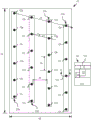
Turning now to the drawings, and in particular to fig. 1, an exemplary fluid ejection die 10 is illustrated. As shown, the fluid-ejecting die 10 may include a plurality of nozzles 12a-x arranged along a die length 14 and a die width 16. As used herein, adjacent nozzles may be used to describe respective nozzles 12a-x having proximate locations along the length 14 of the die. For example, a first nozzle 12a, which may be described as having a first nozzle position, may be an adjacent nozzle to a second nozzle 12b, which second nozzle 12b may be described as having a second nozzle position. The first and second nozzles 12a, 12b may also be described as a pair of adjacent nozzles or a pair of adjacent nozzles. In the exemplary die 10 of fig. 1, the nozzles 12a-x may be described as corresponding to respective nozzle locations based on the positioning of the nozzles 12a relative to the length 14 of the die. Thus, in this example, the die 10 includes a first nozzle 12a in a first nozzle position, a second nozzle 12b in a second nozzle position, and the same nozzle position names are used for the third through 24 th nozzle positions 12c-12x, respectively.
Additionally, in this example, a set of adjacent nozzles and a set of adjacent nozzles may be used to represent a group of nozzles having proximate locations along the length 14 of the die 10, i.e., a set of adjacent nozzles may include at least two nozzles 12a-x having sequential nozzle locations. For example, the first nozzle 12a, the second nozzle 12b, and the third nozzle 12c may be considered a set of adjacent nozzles. Similarly, the first nozzle 12a, the second nozzle 12b, the third nozzle 12c, and the fourth nozzle 12d may be considered a set of adjacent nozzles.
Thus, in the example of FIG. 1, nozzles 12a-x include at least one corresponding pair of adjacent nozzles located at different die width locations along the width of the fluid ejecting die. To illustrate by way of example, the first nozzle 12a and the second nozzle 12b are a pair of respective adjacent nozzles, and the first nozzle 12a and the second nozzle 12b are located at different positions along the width 16 of the die. Similarly, the second nozzle 12b and the third nozzle 12c are a pair of respective adjacent nozzles, and the second nozzle 12b and the third nozzle 12c are located at different die width positions along the width 16 of the die. Further, in this example, the first nozzle 12a, the second nozzle 12b, the third nozzle 12c, and the fourth nozzle 12d are a set of adjacent nozzles, and at least one nozzle of the set of respective adjacent nozzles 12a-d is located at a different die width 16 location. Notably, in this example, each nozzle 12a-d in the set of corresponding adjacent nozzles 12a-d is located at a different die width 16 location. Thus, as shown in fig. 1, the nozzles 12a-x of the fluid-ejecting die 10 are arranged such that for pairs and groups of adjacent nozzles, at least one respective nozzle in each group of adjacent nozzles is located at a different die width 16 location.
Further, it will be noted that the example of the fluid-ejecting die 10 of FIG. 1 includes at least one nozzle 12a-x per nozzle location. Thus, it can be appreciated that the nozzles 12a-x of the fluid-ejecting dies may be fluidly coupled to a single fluid source. For example, if fluid ejection die 10 corresponds to a printhead, nozzles 12a-x may all be coupled to a single source of fluid printing material of a single color. As another example, if fluid ejection die 10 corresponds to a printhead for an additive manufacturing system, nozzles 12a-x may be fluidically coupled to a single source of 3D printing material, such as a fluidic adhesive, a fluidic fining agent, a fluidic surface treatment material, and so forth. Nozzles coupled to a single fluid source may be described as being fluidly coupled together.
In the example shown in FIG. 1, the fluid-ejecting die 10 includes nozzles 12a-x arranged in nozzle columns 20 a-d. As shown, the exemplary first nozzle row 20a includes a first nozzle 12a, a fifth nozzle 12e, a ninth nozzle 12i, a 13 th nozzle 12m, a 17 th nozzle 12q, and a 21 st nozzle 12 u. The exemplary second nozzle column 20b includes a second nozzle 12b, a sixth nozzle 12f, a 10 th nozzle 12j, a 14 th nozzle 12n, an 18 th nozzle 12r, and a 22 th nozzle 12 v. The exemplary third nozzle column 20c includes a third nozzle 12c, a seventh nozzle 12g, an 11 th nozzle 12k, a 15 th nozzle 12o, a 19 th nozzle 12s, and a 23 rd nozzle 12 w. The exemplary fourth nozzle column 20d includes a fourth nozzle 12d, an eighth nozzle 12h, a 12 th nozzle 12l, a 16 th nozzle 12p, a 20 th nozzle 12t, and a 24 th nozzle 12 x.
As shown, adjacent nozzles are distributed across the width 16 of the die in different nozzle columns 20 a-d. Further, the nozzles 12a-x of each nozzle column 20a-d are offset along the die length 14 and the die width 16 such that the corresponding nozzle of each nozzle column 20a-d has an oblique orientation angle with the adjacent nozzle 12 a-x. An exemplary orientation angle 22 between adjacent nozzles is illustrated in fig. 1 between sixth nozzle 12f and seventh nozzle 12 g. Thus, adjacent nozzles located in different nozzle columns 20a-d may be arranged along an oblique line 24 with respect to the die length 14 and the die width 16. As may be noted, the diagonal line 24 may correspond to the orientation angle 22 between adjacent nozzles. Further, it may also be noted that, in some examples, the size of a set of adjacent nozzles may correspond to the number of nozzle columns. In the example of FIG. 1, the size of the set of adjacent nozzles may be four nozzles and the number of nozzle columns 20a-d may also be four. Thus, for a group of four adjacent nozzles, each respective nozzle of the group may be arranged in a different respective nozzle column 20 a-d.
Furthermore, the example of FIG. 1 illustrates an exemplary arrangement of nozzles 12a-x that may be implemented in other examples. As shown in FIG. 1, the nozzles 12a-x of the respective nozzle columns 20a-d may be arranged such that a nozzle-to-nozzle distance between at least some of the nozzles 12a-x of the respective nozzle columns 20a-d may be at least 100 micrometers (μm). In some examples, the nozzle-to-nozzle distance 24 of at least some of the nozzles of the respective nozzle columns 20a-d may be in a range of approximately 100 μm to approximately 400 μm. In the example of FIG. 1, the adjacent nozzles 12a-x of the respective nozzle column 20a-d may be referred to as sequential nozzles 12a-x of the respective nozzle column 20 a-d. For purposes of illustration by way of example, the first nozzle 12a and the fifth nozzle 12e may be referred to as sequential nozzles of the respective first nozzle column 20 a. Similarly, the second nozzle 12b and the sixth nozzle 12f may be referred to as sequential nozzles of the corresponding second nozzle column 20 b. Thus, the nozzle-to-nozzle distance 24 of the nozzles 12a-x of the respective column 20a-d may refer to the distance between sequential nozzles 12a-x of the respective column 20 a-d.
Also, the example of fig. 1 also illustrates an arrangement of nozzle columns that may be implemented in other examples. As shown, the distance 26 between the nozzle columns (which may be referred to as the nozzle column-to-nozzle column distance) may be at least about 100 μm. In some examples, the distance 26 between the nozzle rows may be in a range of about 100 μm to about 400 μm.
In fig. 1, a cross-sectional view 30 along line a-a is provided. As shown in this example, for each respective nozzle (an exemplary cross-sectional view 30 is provided for nozzle 16, 12 p), the fluid-ejecting die 10 also includes a fluid-ejecting chamber 32, the fluid-ejecting chamber 32 being disposed proximate to and fluidly coupled with nozzle 12 p. Die 10 also includes at least one fluid feed hole 34 fluidly coupled to fluid ejection chamber 32. Thus, in examples contemplated herein, fluid may flow to fluid ejection chamber 32 through fluid feed holes 34, and fluid may be ejected from fluid ejection chamber 32 through nozzles 12 p. As shown in cross-sectional view 30, fluid ejecting die 10 may include an array of fluid feed holes 34 formed through a surface opposite the surface through which nozzles 12p are formed.
As can be appreciated with respect to fig. 1, the number of nozzles is shown for clarity. Examples of fluid ejection dies may include more nozzles in more or fewer nozzle columns. In some example fluid ejection dies, the die may include about 2000 to about 6000 nozzles. Additionally, some example nozzle columns of such example fluid ejection dies may include about 40 to about 300 nozzles per column.
Further, in some examples, the spacing between the nozzles of the respective nozzle columns (e.g., the distance between the first and fifth nozzles 12a and 12e of fig. 1) may be about 50 μm to about 500 μm. In other examples, the spacing between nozzles of the respective nozzle columns may be at least 100 μm. Similarly, in some examples, the spacing between nozzle columns (e.g., the distance between the first nozzle column 20a and the second nozzle column 20b in fig. 1) may be about 50 μm to about 500 μm. In some examples, the spacing between nozzle columns may be at least 100 μm.
Further, as shown in fig. 1, the nozzle columns may be arranged in an offset manner such that for a set of nozzle columns, at least one nozzle is located at each respective nozzle location (where that nozzle location corresponds to a location along the length of the die). Thus, it will be appreciated that in such examples, the orientation angle between adjacent nozzles (e.g., the orientation angle 22 shown in fig. 1) may be such that the nozzles of different nozzle columns are arranged in unique nozzle positions. In other words, the diagonal arrangement of nozzles across the length and width of the die is such that the nozzles of different nozzle columns are adjacent nozzles and the nozzles of different nozzle columns are not located at a common nozzle location. In some examples, the orientation angle between adjacent nozzles may be about 10 ° to about 45 °. In some examples, the orientation angle between adjacent nozzles may be at least 20 °. In other examples, the orientation angle may be less than about 75 °. Further, the nozzles of the respective nozzle columns may be offset relative to the width of the die to adjust for drop ejection timing. Thus, while the examples shown herein may illustrate aligned diagonal lines and columns of nozzles, other examples may include in-line (columnar) nozzles with an offset along the width of the die. In some examples, the respective columns of nozzles may be offset along the width by about 5 μm to about 30 μm.
Thus, the spacing between nozzles, the spacing between nozzle columns, and the orientation angle between adjacent nozzles may be defined such that the nozzle columns are arranged in a staggered and offset manner across the die. In such examples, the spacing between nozzles, the spacing between nozzle columns, and/or the orientation angle between adjacent nozzles may facilitate ejection of fluid drops through nozzles that control the generation of air flow associated with such ejection.
In some examples, the columns of nozzles may be spaced across the width of the die, and the columns of nozzles may be staggered and/or offset along the length of the die. In some examples, at least some nozzles of different nozzle columns may be staggered according to an orientation angle. The arrangement of nozzles 12a-x and nozzle columns 20a-d may be referred to as staggered nozzle columns. Thus, examples contemplated herein may include at least four staggered nozzle columns.
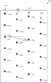
Fig. 2 provides an exemplary fluid ejection die 50. As shown, the die 50 includes a plurality of nozzles 52a-x arranged along a die length 54 and a die width 56. As previously discussed, the nozzle locations correspond to locations along the die length 54, and in this example, the die 50 includes a first nozzle 52a at the first nozzle location through a 24 th nozzle 52x at the 24 th nozzle location. The nozzles 52a-x of the exemplary die 50 are arranged such that for a set of adjacent nozzles (i.e., nozzles having sequential nozzle positions), at least a subset of the set of adjacent nozzles are located at different positions along the width 56 of the die. For example, the first nozzle 52a (at a first nozzle position) and the second nozzle 52b (at a second nozzle position) may be considered a set of adjacent nozzles. As shown, the first nozzle 52a and the second nozzle 52b are spaced relative to the die width 56, i.e., the first nozzle 52a and the second nozzle 52b are located at different die width locations along the width of the fluid-ejecting die 50.
In the exemplary die 50 of FIG. 2, the nozzles 52a-x are arranged in a first nozzle column 60a and a second nozzle column 60 b. In this example, the fluid-ejecting die 50 also includes an array of ribs 64a, 64b (illustrated in phantom) formed on the back surface of the die 50. As shown, the array of ribs 64a, 64b is aligned with the nozzle columns 60a, 60b of the exemplary die 50. A cross-sectional view 70 along line B-B provides additional detail regarding the arrangement of ribs 64a, 64B and other features of fluid-ejecting die 50. For each respective nozzle 52a-x (in the exemplary cross-sectional view, nozzle 16 p is illustrated), fluid-ejecting die 50 also includes a respective first fluid feed hole 72a and a respective second fluid feed hole 72b fluidly coupled to a respective fluid-ejecting chamber 74. Each respective fluid ejection chamber 74 is also fluidly coupled to a respective nozzle 52 p.
As shown, the fluid ejection chambers 74 are arranged above respective ribs 64b in the array of ribs such that the first fluid supply holes 72a are located on a first side of the respective ribs 64b and the second fluid supply holes 72b are located on a second side of the respective ribs 64 b. The array of ribs 64a, 64b may form fluid circulation channels 80, 82 across the die 50. Accordingly, fluid may be input into the respective fluid ejection chambers 74 from the respective first fluid circulation channels 80 via the respective first fluid supply holes 72 a. Fluid may be output from the respective fluid ejection chamber 74 to the respective second fluid circulation channel 82 via the respective second fluid supply hole 72 b. This exemplary fluid flow, which may be referred to as micro-recirculation, is illustrated in dashed lines in fig. 2. Although not shown, it is understood that fluid may also be output from the respective fluid ejection chambers as drops via the respective nozzles 52 p.
As shown in cross-sectional view 70 of fig. 2, die 50 may also include, for each respective nozzle 52p, a respective first fluid actuator 90 disposed in a respective fluid ejection chamber 74. Actuation of a respective first fluid actuator 90 may cause ejection of a drop from a respective fluid ejection chamber 74. In some examples, the first fluid actuator 90 may be a thermistor-based fluid actuator, which may be referred to as a thermal fluid actuator. The die 50 may also include a corresponding second fluid actuator 92. Actuation of the respective second fluid actuator 92 may cause fluid to flow from the respective fluid ejection chamber 74 into the respective second fluid circulation channel 82. Thus, although nozzles 52a-x may be fluidly coupled together for a fluid source, ribs 64a-b may fluidly separate fluid input to ejection chamber 74 and fluid output from ejection chamber 74.
Although not illustrated in the exemplary cross-sectional view 70, it can be appreciated that the respective first fluid circulation channels 80, the surfaces of which may be defined by the first and second ribs 64a, 64b in the array of ribs, may also be fluidly coupled to the respective first fluid supply holes for all of the respective fluid ejection chambers of the die 50. Accordingly, the respective first fluid circulation channels 80 may be fluid input supplies for the nozzles 52a-x of the die 50. Fluid circulating through fluid ejection chambers 74 (e.g., the exemplary flow shown in cross-sectional view 70) may be fluidly separated from respective first fluid circulation channels 80, and thus, may be fluidly separated from a fluid input supply to respective ejection chambers 74 by first and second ribs 64a, 64 b.
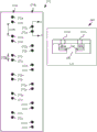
Fig. 3 provides a block diagram of an exemplary fluid ejection die 100. In this example, the die 100 includes a plurality of nozzles 102a-x arranged along a die length 104 and a die width 106. In particular, the nozzles 102a-x are arranged such that one nozzle 102a-x is positioned at each die length 104 location and adjacent nozzles (e.g., a first nozzle 102a, a second nozzle 102b, a third nozzle 102 c; or a fourth nozzle 102d and a fifth nozzle 102 e) are positioned at different die widths 106 locations. In this example, the nozzles 102a-x are arranged in four nozzle columns 110 a-d.
In addition, fluid ejecting die 100 of fig. 3 includes an array of ribs 112a, 112 b. In a fluid die example, such as the example die 100 of fig. 3, the orifice of each nozzle 102a-x may be formed on the front surface of the fluid-ejecting die 100. An array of ribs 112a, 112b may be disposed on the opposing rear surface of fluid-ejecting die 100. As previously discussed, the array of ribs 112a, 112b may form fluid circulation channels 114, 116a, b through the fluid ejection die 100. For each nozzle 102a-x, fluid-ejecting die 100 may also include a respective first fluid feed hole 120a-x and a respective second fluid feed hole 122 a-x. In this example, each first fluid feed hole 120a-x may be fluidly coupled to a first fluid circulation channel 114 in an array of fluid circulation channels 114, 116a, b. Similarly, each second fluid feed hole 122a-x may be fluidly coupled to a second fluid circulation channel 116a, b. Thus, in this example, the fluid-ejecting die includes an array of fluid feed holes 120a-x, 122a-x formed through a surface of the die 100 opposite the surface through which the nozzles 102a-x are formed. In this example, the fluid-ejecting die 100 includes two fluid feed holes 120a-x, 122a-x for each respective ejection chamber and nozzle 102 a-x. Further, as shown, an array of fluid feed holes 120a-x, 122a-x may be formed through the surface of the die 100 that also engage the ribs 112 a-b. Notably, the nozzles 102a-x can be formed through a top surface of the die 100, and the fluid feed holes 122a-x can be formed through a bottom surface of the die 100, which can be adjacent to the ribs 112a-b, and which can define an inner surface of the fluid passages 114, 116 a-b.
Although not shown in this example for clarity, fluid die 100 may include a respective fluid ejection chamber disposed below each respective nozzle 102a-x, and fluid ejection die 100 may further include at least one respective fluid actuator disposed in each respective fluid ejection chamber. As shown in this example, each nozzle 102a-x (and the respective fluid ejection chamber disposed therebelow) may be fluidly coupled to a respective first fluid feed hole 120a-x and a respective second fluid feed hole 122a-x by a respective microfluidic channel 128.
As can be appreciated, in this example, each respective first fluid feed hole 120a-x can be a fluid input, wherein fresh fluid can be sourced from the first fluid circulation channel 114. Likewise, each respective second fluid feed hole may be a fluid outlet, wherein fluid may be delivered to the second fluid circulation channels 116a-b when fluid is not being ejected through the nozzles 102 a-x. Thus, in some examples, fluid may be input from the first fluid circulation channel 114 into the respective ejection chambers associated with the respective nozzles 102a-x via the respective first fluid supply holes 120a-x and the respective microfluidic channels 128. Fluid drops may be ejected from respective ejection chambers through respective nozzles 102a-x by actuation of at least one fluid actuator disposed in the respective ejection chambers. Fluid may also be delivered (i.e., output) from the respective fluid ejection chamber to the second fluid circulation channels 116a-b through the microfluidic channels 128 and the respective second fluid feed holes 122 a-x. Although not included in this example, similar to the example of fig. 2, fluid ejection die 100 may include at least one fluid actuator disposed in each microfluidic channel 128 that may be actuated to facilitate micro-recirculation through each fluid ejection chamber. In some examples, the at least one fluid actuator may be disposed proximate a respective first fluid feed hole to pump fluid into the ejection chamber. In some examples, the at least one fluid actuator may be disposed proximate a respective second fluid feed hole to pump fluid from the ejection chamber.
The delivery of fluid from the fluid input through the ejection chamber and to the fluid output may be referred to as micro-recirculation. In some example fluid ejection dies and fluid ejection devices similar to the examples described herein, the fluid used therein may include a solid suspended in a liquid carrier. Micro-recirculation of such fluids may reduce settling of such solids in the liquid carrier in the fluid ejection chamber. By way of example, a printhead according to the present invention may use a fluid printing material, such as ink, liquid toner, 3D printer reagents, or other such materials. In such exemplary printheads, aspects of the fluid circulation channels, rib arrays, and micro-recirculation channels may be implemented to facilitate movement of the fluid marking material throughout the fluidic architecture of the printhead to thereby maintain suspension of solids in the liquid carrier of the marking material.
Turning now to fig. 4A-E, these figures provide a portion of an exemplary fluid-ejecting die with various exemplary nozzle arrangements in which the nozzles are arranged across the length and width of the die such that, for each set of adjacent nozzles, a respective subset of each set of adjacent nozzles is located at different die-width locations along the width of the die. Further, it may also be noted that in these examples, a single nozzle may be positioned at each nozzle location for the respective fluid inputs.
In fig. 4A, an exemplary fluid ejection die 200 is illustrated. As shown, the nozzles 202a-x are arranged along the length and width of the die. In this example, the nozzles 202a-x are arranged in eight nozzle columns 204 a-h. In this example, the first nozzle column 204a may include a first nozzle 202a, a ninth nozzle 202i, and a 17 th nozzle 202 q. The second nozzle column 204b may include a sixth nozzle 202f, a 14 th nozzle 202n, and a 22 nd nozzle 202 v. The third nozzle column 204c may include a third nozzle 202c, an 11 th nozzle 202k, and a 19 th nozzle 202 s. The fourth nozzle column 204d may include eighth, 16 th and 24 th nozzles 202h, 202p and 202 x. The fifth nozzle column 204e may include a fifth nozzle 202e, a 13 th nozzle 202m, and a 21 st nozzle 202 u. The sixth nozzle column 204f may include the second nozzle 202b, the 10 th nozzle 202j, and the 18 th nozzle 202 r. The seventh nozzle column 204g may include a seventh nozzle 202g, a 15 th nozzle 202o, and a 23 th nozzle 202 w. The eighth nozzle column 204g may include a fourth nozzle 202d, a 12 th nozzle 202l, and a 20 th nozzle 202 t.
In this example, the designation of first nozzle 202a, second nozzle 202b, etc., refers to the location of the nozzles along the length of die 200, which may be referred to as nozzle locations. Notably, as shown in fig. 4A, at least one nozzle is positioned at each nozzle location along the width of the die 200. Thus, to perform drop ejection of fluid for each nozzle location along the width of the die 200, all of the nozzles 202a-x of this example may be fluidly coupled with other nozzles 202 a-x.
Additionally, in this example, the nozzle columns 204a-h may be arranged such that the distances between the nozzle columns may be different. As shown, the first nozzle column 204a and the second nozzle column 204b may be separated by a first distance 206 a. The second nozzle column 204a and the third nozzle column 204c may be separated by a second distance 206b that is different than the first distance 206 a. The other nozzle columns 204c-h may be similarly arranged. For example, the interval between the third nozzle column 204c and the fourth nozzle column 204d may be a first distance 206a, and the interval between the fourth nozzle column and the fifth nozzle column 204e may be a second distance 206 b.
Fig. 4B illustrates an exemplary fluid-ejecting die 250 having a plurality of nozzles 252a-x arranged in four nozzle columns 254a-d along the length and width of the die 250. Further, in FIG. 4B, it may be noted that nozzles 252a-x may be arranged such that some adjacent nozzles may have different orientation angles between them. For example, referring to the example ninth nozzle 252i, 10 th nozzle 252j, and 11 th nozzle 252k, as shown, the ninth nozzle 252i and 10 th nozzle 252j may be arranged at a first orientation angle 256 along the length and width of the die 250. And the 10 th nozzle 252j and the 11 th nozzle 252k may be arranged at a second orientation angle 258 different from the first orientation angle 256 along the length and width of the die.
Fig. 4C illustrates an exemplary fluid-ejecting die 270 having a plurality of nozzles 272a-x arranged in two nozzle columns 274a, 274b along the length and width of the fluid-ejecting die 270. As shown in fig. 4C, in some examples, the nozzles 272a-x of the respective nozzle columns 274a, 274b may be spaced apart by different distances. To illustrate by way of example, and with reference to fig. 4C, a first distance 276a between a ninth nozzle 272i and a 10 th nozzle 272j of a first nozzle column 274a of the die 270 may be different than a second distance 276b between a second nozzle 272b and a fifth nozzle 272e in the first nozzle column 274 a. The nozzles of a common nozzle column may be referred to as column nozzles (columns). Nozzles in a nozzle column that are close to each other may be referred to as sequential column nozzles. For example, the first nozzle 272a and the second nozzle 272b may be referred to as sequential row nozzles. Similarly, the second nozzle 272b and the fifth nozzle 272e may be considered as sequential in-line nozzles. Further, the ninth nozzle 272i and the 10 th nozzle 272j may be referred to as sequential row nozzles. Returning to the example above, the first distance 276a between the sequential rows of nozzles 272i, 272 may be less than 50 μm, and the second distance 276b between the sequential rows of nozzles 272b, 272e may be at least 100 μm. As another example, the first distance may be less than 25 μm, and the second distance 276b may be about 100 μm to about 400 μm. Further, although not labeled in fig. 4C, it may be noted that the orientation angle between adjacent nozzles may be different for nozzles 272a-x of exemplary die 270. For example, some adjacent nozzle pairs may be arranged at approximately orthogonal orientation angles (e.g., an orientation angle between first nozzle 272a and second nozzle 272 b). Other adjacent nozzle pairs may be arranged at acute orientation angles (e.g., between second nozzle 272b and third nozzle 272 c).
A cross-sectional view 280 along the line C-C is provided in fig. 4C. As shown, the fluid-ejecting die 270 may include at least one fluid feed hole 282 for at least two nozzles 272c, 272 d. Each nozzle 272c, 272d can be fluidly coupled to a fluid ejection chamber 284a, 284b, and each fluid ejection chamber 284a, 284b can be fluidly coupled to the at least one fluid feed hole 282. In addition, similar to other examples, the die 270 may include at least one fluid actuator 286 disposed in each fluid ejection chamber 284a, 284 b.
In fig. 4D, the exemplary fluid-ejecting die 300 includes a plurality of nozzles 302a-x arranged in two nozzle columns 304a, 304b along the length and width of the die 300. In this example, the group of three adjacent nozzles 302a-x may be sequential columns of nozzles. Groups of three adjacent nozzles may be alternately arranged in respective nozzle columns 304a, 304b such that the three nozzles 302a-x of each group are spaced along the die width from the respective group of nozzles 302a-x corresponding to the next three adjacent nozzles. Thus, similar to the example of fig. 4C, at least some nozzles 302a-x of respective nozzle columns 304a, 304b may be separated by a first distance (an example of which is indicated by dimension line 306 a), and at least some nozzles 302a-x of respective nozzle columns 304a, 304b may be separated by a second distance (an example of which is indicated by dimension line 306 b), wherein the first and second distances may be different.
Fig. 4E illustrates an exemplary fluid-ejecting die 350, wherein a plurality of nozzles 352a-x are arranged in at least three nozzle columns 354a-c along the length and width of the die 350. Thus, some examples may include at least three staggered nozzle columns. In this example, the array of ribs 356 is illustrated in dashed lines because the ribs are located on the underside of the die 350. As shown, the ribs 356 may be aligned with diagonal lines along which groups of adjacent nozzles may be arranged.
Turning now to fig. 5A, an exemplary fluid-ejecting die 400 is provided that includes a plurality of nozzles 402a-x arranged in at least four nozzle columns 404a-d along a die length and a die width. In this example, the set of adjacent nozzles 402a-x may include four nozzles (e.g., the first set of adjacent nozzles may be the first nozzle 402a through the fourth nozzle 402 d). Further, the nozzles within adjacent nozzle groups may be arranged along a diagonal line 406 with respect to the length and width of the die. An exemplary orientation angle 408 is provided between the first nozzle 402a and the second nozzle 402b, wherein the orientation angle 408 may correspond to a diagonal line 406 along which adjacent nozzles may be arranged. In some examples, the diagonal line 406 along which adjacent nozzles 402a-x may be arranged may be oblique with respect to the length of the die, and the diagonal line 406 may be oblique with respect to the width of the die. In an example similar to the example die 400, each set of adjacent nozzles (e.g., the first nozzle 402 a-fourth nozzle 402 d; the fifth nozzle 402 e-eighth nozzle 402 h; etc.) may be arranged along parallel diagonal lines.
Fig. 5B provides a cross-sectional view 430 along a line of sight D-D of fig. 5A, and fig. 5C provides a cross-sectional view 431 of the exemplary die 400 of fig. 5A along a line of sight E-E. In this example, the die 400 includes an array of ribs 432 that define an array of fluid circulation channels 434 a-b. In addition, the cross-sectional view 430 of FIG. 5B includes dashed line depictions of the fourth nozzle 402d, the seventh nozzle 402g, and the 11 th nozzle 402k to illustrate the relative positioning of these nozzles 402d, 402g, 402k with respect to the ribs 432 in the rib array and the fluid circulation channels 434a-B defined thereby. Referring to fig. 5C, this figure includes dashed line representations of the 21 st nozzle 402u, the 22 nd nozzle 402v, the 23 rd nozzle 402w, and the 24 th nozzle 402 x.
Further, it will be appreciated that the line of sight D-D along which the cross-sectional view 430 is presented is approximately orthogonal to the diagonal line 406, along which diagonal line 406 groups of adjacent nozzles may be arranged. Thus, the other nozzles of the adjacent nozzle group in which the fourth nozzle 402d, the seventh nozzle 402g, and the 11 th nozzle 402k are grouped may be aligned with the depicted nozzles in the cross-sectional view 430. Similarly, it can be appreciated that the other nozzles of the first, second, third, and fourth nozzle columns 404a, 404b, 404C, 404d can be aligned with the example nozzles 402u-x shown in the cross-sectional view 431 of FIG. 5C.
Additionally, as shown in dashed lines, each respective nozzle 402d, 402g, 402k, 402u-x may be fluidly coupled to a respective fluid ejection chamber 438a-c, 438 u-x. Although not shown, die 400 may include at least one fluid actuator in each fluid ejection chamber 438a-c, 438 u-x. Further, each respective fluid ejection chamber 438a-c, 438u-x may be fluidly coupled to a respective first fluid feed hole 440a-c, and each respective fluid ejection chamber 438a-c, 438u-x may be fluidly coupled to a respective second fluid feed hole 442a-c, 442 u-x. In the cross-sectional view 431 of fig. 5C, the first respective fluid supply hole is not shown because the cross-sectional line is positioned so as not to include the first respective fluid supply hole. The respective second fluid feed holes 442u-x for the respective ejection chambers 438u-x are illustrated in phantom because they may be spaced from the line of sight.
In this example, a top surface 450 of each rib 432 in the array of ribs can be adjacent to and engage a bottom surface 452 of the substrate 454, and the fluid ejection chambers and fluid feed holes can be at least partially formed in the bottom surface 452. Thus, the bottom surface 452 of the substrate may form an inner surface of the fluid circulation channels 434 a-b. As shown in fig. 5B, the bottom surface 452 of the substrate may be opposite the top surface 456 of the substrate 454, wherein the top surface 456 of the substrate 454 may be adjacent a nozzle layer 460 in which the nozzles 402d, 402g, 402k may be formed. In this example, a portion of fluid ejection chambers 438a-c, 438u-x may be defined by a surface of nozzle layer 460 disposed over a portion of fluid ejection chambers 438a-c formed in substrate 454. In other examples, the ejection chambers, nozzles, and supply holes may be formed in more or fewer layers and substrates. The bottom surface 462 of each rib 432 may be adjacent to the top surface 464 of an interposer (interposer) 466. Thus, in this example, fluid circulation channels 434a-b may be defined by fluid circulation ribs 432, substrate 454, and interposer 466. 5B-5C, the fluid-ejecting die 400 includes an array of fluid feed holes 440a-C, 442u-x formed through a bottom surface 452 of the fluid-ejecting die 400.
In examples similar to the examples of fig. 5A-C, the fluid circulation channels may be arranged to facilitate circulation of fluid through the fluid ejection chambers. In this example, respective first fluid feed holes 440a-c may be fluidly coupled to respective first fluid circulation channels 434a such that fluid may be delivered from respective first fluid circulation channels 434a to respective fluid ejection chambers 438a-c, 438u-x via respective first fluid feed holes 440 a-c. Similarly, each respective second fluid feed hole 442a-c, 442u-x can be fluidly coupled to a respective second fluid circulation channel 434b such that fluid can be delivered from a respective fluid ejection chamber 438a-c, 438u-x to the respective second fluid circulation channel 434b via the respective second fluid feed hole 442a-c, 442 u-x. Respective first fluid circulation channels 434a and respective second fluid circulation channels 434b may be fluidly separated by ribs 432 along some portions of die 400 such that fluid flow may only occur through supply holes 440a-c, 442a-c and ejection chambers 438 a-c.
Accordingly, the respective first fluid circulation channel 434a may correspond to a fluid input channel through which fresh fluid may be input to the fluid ejection chambers 438 a-c. Some of the fluid input to ejection chambers 438a-c may be ejected as fluid drops through nozzles 402d, 402g, 402 k. However, to facilitate circulation through ejection chambers 438a-c, some fluid may be delivered from ejection chambers 438a-c back to respective second fluid circulation channels 434b, which respective second fluid circulation channels 434b may correspond to fluid output channels.
Referring to fig. 5A and 5B, it should be noted that the ribs 432 in the rib array and the fluid circulation channels 434a-B partially defined thereby may be parallel to the diagonal line 406 through which adjacent nozzles 402a-x are also arranged. Further, as shown, in this example, the respective first fluid supply holes of the nozzles 402a-x of each set of adjacent nozzles can be commonly coupled to a respective fluid circulation channel 434a, and the respective second fluid supply holes of the nozzles 402a-x of each set of adjacent nozzles can be commonly coupled to a respective fluid circulation channel 434 b. In this example, the fluid arrangement of ejection chambers 438a-c, first fluid feed holes 440a-c, and second fluid feed holes 442a-c may be described as spanning respective ribs 432 in a rib array.
For example, as shown in fig. 5B, the respective first fluid supply holes 440B coupled to the seventh nozzle 402g and the respective first fluid supply holes 440c coupled to the 11 th nozzle 402k are fluidly coupled to the respective first fluid circulation channels 434 a. Similarly, a respective second fluid feed hole 442a coupled to fourth nozzle 402d and a respective second fluid feed hole 442b coupled to seventh nozzle 402g are fluidly coupled to respective second fluid circulation channels 434 b. Since adjacent nozzles 402a-x are aligned with the nozzles 402d, 402g, 402k shown in FIG. 5B along the respective ribs 432, it may be noted that the fluid feed holes associated with the adjacent nozzles of each respective nozzle 402d, 402g, 402k shown may be similarly arranged.
As shown in fig. 5B, ejection chambers 438a-c may be disposed above respective ribs 432 in the substrate, and fluid feed holes 440a-c, 442a-c coupled to respective fluid ejection chambers 438a-c may be located on opposite sides of respective ribs 432, such that fluid input to respective ejection chambers 438a-c via respective first fluid feed holes 440a-c may be fluidically separated from fluid output from respective ejection chambers 438a-c via respective second fluid feed holes 442 a-c.
As shown in fig. 5B-C, the top surface 464 of the interposer 466 can form a surface of the fluid circulation channels 434 a-B. Further, interposer 466 may be positioned relative to substrate 454 and ribs 432 such that die fluid input 480 and die fluid output 482 may be at least partially defined by interposer 466 and/or substrate 454. In such an example, die fluid input 480 may be fluidly coupled to fluid circulation channels 434a-b, and die fluid output 482 may be fluidly coupled to fluid circulation channels 434 a-b.
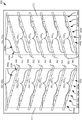
Fig. 6 provides an illustration of an exemplary fluid-ejecting die 500 in which a plurality of nozzles are arranged along the length and width of the fluid-ejecting die 500. In this example, the nozzles are arranged in eight nozzle columns 502a-h, which may be referred to as staggered nozzle columns. Accordingly, some examples herein may include at least eight staggered nozzle columns. As may be noted, these nozzles are not labeled in fig. 6 for clarity. FIG. 7 provides an illustration of an exemplary fluid-ejecting die 550, wherein a first plurality of nozzles 5521-55248And a second plurality of nozzles 5541-55448Arranged along the length and width of fluid ejection die 550. In this example, the first plurality of nozzles 5521-55248Are arranged in a first set of nozzle columns 556a-h, and the second plurality of nozzles 5541-55448Are arranged in a second set of nozzle columns 558 a-h. Thus, some examples may include at least 16 staggered nozzle columns. In some such examples, an exemplary die may include a first set of at least 8 staggered nozzle columns, and a second set of at least 8 staggered nozzle columns.
In this example, the die 550 may include a first array of ribs 560 defining a first array of fluid circulation channels, and the die 550 may also include a second array of ribs 562 defining a second array of fluid circulation channels. In FIG. 7, the array of ribs 560, 562 is illustrated in dashed lines because of the arrayWith rows at the nozzles 5521-55248、5541-55448And below the corresponding fluid ejection chamber (not shown). Further, the first array of ribs 560 may be disposed proximate to the first interposer 570 such that the first interposer forms a surface of the first array of fluid circulation channels. The second array of ribs 562 can be disposed proximate to the second interposer 572 such that the second interposer 572 forms a surface of the second array of fluid circulation channels. As may be noted, in this example, the arrangement of the array of ribs 560, 562, fluid circulation channels, and interposers 570, 572 may be similar to the arrangement of similar elements of the example die 400 shown in fig. 5A-C. Thus, although not shown, similar to the example of fig. 5A-C, the example of fig. 7 may include a respective die fluid input and a respective die fluid output defined at least in part by each interposer 570, 572 for each of the plurality of nozzles 5521-55248、5541-55448。
Further, in this example, the first plurality of nozzles 5521-55248Adjacent sets of nozzles may be arranged in a diagonal arrangement. For example, the first through eighth nozzles 552 of the first plurality of nozzles1-5528Can be considered as a set of adjacent nozzles arranged diagonally. As shown, the ribs 560 (and the array of fluid circulation channels defined thereby) may be aligned with diagonally arranged adjacent sets of nozzles. The second plurality of nozzles 5541-55448And ribs 562 in the second array may be similarly arranged along parallel diagonal lines with respect to the length and width of die 550.
Further, in the example of FIG. 7, the first plurality of nozzles 5521-55248(and the fluid ejection chambers associated therewith) may correspond to a first fluid type, and the second plurality of nozzles 5541-55448(and the fluid ejection chamber associated therewith) may correspond to the second fluid type. For example, if the fluid-ejecting die 550 of fig. 7 is in the form of a printhead, the first plurality of fluid nozzles 5521-55248May correspond to a first colorant (e.g., a first ink color), and the second colorantMultiple fluid nozzles 5541-55448May correspond to a second colorant (e.g., a second ink color). As another example, if the fluid-ejection die 550 of fig. 7 is in the form of a fluid-ejection die implemented in an additive manufacturing system (e.g., a 3-dimensional printer), the first plurality of nozzles 5521-55248May correspond to flux, and the second plurality of nozzles 5541-55448May correspond to a fine agent. Thus, as shown and described with respect to this example, the first plurality of nozzles 5521-55248Can be fluidly coupled together, and the second plurality of nozzles 5541-55448May be fluidly coupled together. Thus, in some examples, the first plurality of nozzles 5521-55248May be associated with the second plurality of nozzles 5541-55448And (4) separating the fluid. In other examples, the first plurality of nozzles 5521-55248May be fluidly coupled to the second plurality of nozzles 5541-55448. Fig. 8 provides a block diagram of an exemplary fluid-ejecting die 600. In this example, the fluid-ejecting die includes a plurality of nozzles 602 distributed across the length and width of the fluid-ejecting die 600 such that at least one respective pair of adjacent nozzles is located at different die-width locations along the width of the fluid-ejecting die 600. As previously discussed, the nozzle 602 may include a nozzle orifice 604 formed on a surface of a layer in which the nozzle 602 is formed, through which nozzle orifice 604 a drop of fluid may be ejected. The die 600 also includes a plurality of ejection chambers 608, the plurality of ejection chambers 608 including, for each respective nozzle 602, a respective ejection chamber 606 fluidly coupled to the nozzle 602. Fluid ejection die 600 also includes at least one fluid actuator 608 disposed in each ejection chamber 606. Fluid-ejecting die 600 also includes an array of fluid feed holes 609 formed on a surface of die 600 opposite the surface through which nozzles 602 are formed. In this example, the array of fluid feed holes 609 of die 600 includes at least one respective fluid feed hole 610 fluidly coupled to each ejection chamber 606.
Fig. 9 provides a block diagram of an exemplary fluid ejection device 650. As shown, fluid ejection device 650 includes a support structure 652, and at least one fluid supply channel 653 can be formed through support structure 652. The fluid-ejection device 650 includes at least one fluid-ejection die 654, wherein the at least one fluid-ejection die 654 may include a plurality of nozzles 655 distributed across a length of the die and a width of the die 654, each nozzle 655 including a nozzle orifice 656 from which a fluid drop may be ejected. Further, the die 654 may include a plurality of ejection chambers 657, wherein, for each respective nozzle 655, the die 650 includes a respective fluid ejection chamber 657 and at least one fluid actuator 658 disposed therein. The fluid-ejecting die 654 further includes an array of fluid feed holes 659, wherein the array of fluid feed holes 659 includes a respective first fluid feed hole 660 and a respective second fluid feed hole 662 fluidly coupled to each respective ejecting chamber 657. Each respective first fluid feed hole 660 can be fluidly coupled to a respective first fluid circulation channel 664, and each respective second fluid feed hole can be fluidly coupled to a respective second fluid circulation channel 668. The first fluid circulation channel 664 and the second fluid circulation channel 668 may be fluidly coupled to the at least one fluid circulation channel 653. Thus, for the fluid-ejection device 650, the at least one fluid-supply channel 653, the fluid- circulation channels 664, 668, the fluid- supply holes 660, 662, the ejection chamber 657, and the nozzle 655 can be fluidically coupled together.
Fig. 10A provides a block diagram illustrating an exemplary layout of a fluid ejection device 700. In this example, fluid ejection device 700 includes a plurality of fluid ejection dies 702a-e arranged along a width 704 of a support structure 706 of fluid ejection device 700. In this example, the plurality of fluid ejection dies 702a-e are arranged end-to-end in a staggered manner along a width 706 of support structure 706. Further, as shown in dashed lines, a first fluid supply channel 708a and a second fluid supply channel 708b may be formed through the support structure 706 along the width 704 of the support structure 706. The first set of fluid ejection dies 702a-c may be arranged generally end-to-end and fluidly coupled to a first fluid supply channel 708a, and the second set of fluid dies 702d-e may be arranged generally end-to-end and fluidly coupled to a second fluid supply channel 708 b.
The detailed view 720 of fig. 10A provides a block diagram illustrating some components of the fluid-ejecting dies 702a-e of the example fluid-ejecting device 700. Similar to other examples described herein, in the example of fig. 10A, the fluid-ejecting die 702d may include a plurality of nozzles 722 distributed along the length and width of the die 702 such that at least one adjacent nozzle of a respective nozzle of the plurality of nozzles is spaced along the width of the die 702. In this example, each nozzle 722 is fluidly coupled to a respective ejection chamber 724, and each ejection chamber 724 is fluidly coupled to at least one supply hole 726. Each fluid feed hole 726 may be fluidly coupled to a respective fluid circulation channel 728. The fluid circulation channel 728 is defined by an array of ribs 730. The fluid circulation channel 728 of the example die 702d may be fluidly coupled to the second fluid supply channel 708 b. Thus, in this example, the nozzle 722 may be fluidly coupled to the second fluid supply channel 708b via the ejection chamber 724, the feed hole 726, and the fluid circulation channel 728.
FIG. 10B provides a cross-sectional view 750 along line F-F of FIG. 10A. In this example, the fluid ejection dies 702c, 702e may be at least partially embedded in the support structure 704. As may be noted in this example, the top surfaces of the fluid ejection dies 702c, 702e may be approximately planar with the top surface of the support structure 706. In other examples, the fluid ejection dies 702c, 702e can be coupled to a surface of the support structure 706. In this example, each fluid ejection die 702c, 702e includes a nozzle, an ejection chamber, and a fluid feed hole 722 and 726 (which are labeled collectively in fig. 10B for clarity). In fig. 10B, the fluid-ejecting dies 702C, 702e may be similar to the example fluid-ejecting die 400 of fig. 5A-C. Accordingly, the die 702 may include an interposer 752 and ribs 730 that define the fluid circulation channels 728. As shown, the interposer 752 of each fluid ejection die 702c, 702e at least partially defines a die fluid input 762 and a die fluid output 764 through which fluid may flow from the fluid supply channels 708a-b into the fluid circulation channel 728 of each fluid ejection die 702c, 702 e.
Further, as shown in FIG. 10B, fluid ejection device 750 can include a fluid separation member 780 positioned in fluid supply channels 708 a-B. In such examples, the fluid separation member 780 can engage the interposer 752. The fluid separation member may fluidically separate a die fluid input 762 and a die fluid output 764 in the fluid channels 708 a-b. In some examples, separating the fluid channels 708a-b by the fluid separation member 780 may facilitate the application of a pressure differential across the die fluid input 762 and the die fluid output 764, wherein such a pressure differential may result in cross-die fluid circulation through the array of fluid circulation channels 728.
Fig. 11 provides a cross-sectional view of an exemplary fluid ejection device 800. In this example, fluid ejection device 800 includes a fluid ejection die 802 coupled to a support structure 804. In this example, fluid ejection die 802 may be similar to exemplary fluid ejection die 550 of fig. 7. Thus, the fluid-ejecting die 800 includes a first plurality of nozzles 806, corresponding ejection chambers, and corresponding fluid feed holes, which are collectively labeled in the example for clarity. The die also includes a second plurality of nozzles 810, corresponding ejection chambers, and corresponding fluid feed holes, all of which are labeled collectively for clarity.
The example die 802 also includes a first interposer 810 and a first array of ribs 812 disposed below the first plurality of nozzles 806, such that the first interposer 810 and the first array of ribs 812 form a first array of fluid circulation channels 814. The fluid ejection device 800 includes a first fluid supply channel 816 formed through the support structure 804 and fluidly coupled to a first die fluid input 818 and a first die fluid output 820 of the fluid ejection die 802. As shown, a first die fluid input 818 and a first die fluid output 820 are fluidly coupled to the first array of fluid circulation channels 814.
In addition, the example die 800 also includes a second array of second interposers 822 and ribs 824 disposed under the second plurality of nozzles 808, such that the second interposers 822 and ribs 824 form a second array of fluid circulation channels 826. Fluid ejection device 800 includes a second fluid supply channel 828 formed through support structure 804 and fluidly coupled to a second die fluid input 830 and a second die fluid output 832. As shown, a second die fluid input 830 and a second die fluid output 832 are fluidly coupled to a second array of fluid circulation channels 826.
As shown in fig. 11, the first plurality of nozzles 806 and corresponding fluidic components (e.g., ejection chambers, fluid supply holes, fluid circulation channels, etc.) fluidly coupled thereto may be fluidly separated from the second plurality of nozzles 808 and corresponding fluidic components fluidly coupled thereto. Thus, different types of fluids may be ejected from first plurality of nozzles 806 and second plurality of nozzles 808. For example, if the fluid ejection device is in the form of a printhead, the first fluid supply channel 816 can deliver printing material of a first color to the first plurality of nozzles 806, and the second fluid supply channel 828 can deliver printing material of a second color to the second plurality of nozzles 808. Further, while only one fluid ejection die 802 is illustrated in the example fluid ejection device of fig. 11, other example fluid ejection devices may include more fluid ejection dies 802. For example, an example fluid ejection device may include a plurality of fluid ejection dies similar to fluid ejection die 802 of fig. 11, where the plurality of fluid ejection dies may be arranged generally end-to-end in a staggered manner along a width of a support structure of the fluid ejection device, similar to the example arrangement shown in fig. 10A.
Further, in fig. 11, the fluid ejection device 800 of fig. 11 includes a fluid separation member 840 disposed in the fluid supply channels 816, 828 and engaging the interposers 810, 822. In such an example, the fluid separation member 840 may fluidically separate the die fluid inputs 818, 830 and the die fluid outputs 820, 832 in the fluid supply channels 816, 828. By fluidically separating the die fluid inputs 818, 830 and the die fluid outputs 820, 832 in the fluid channels 816, 828, fluid flow through the array of fluid circulation channels 814, 826 of the die 802 may be induced by applying a pressure differential between the die fluid inputs 818, 830 and the die fluid outputs 820, 832.
Accordingly, examples provided herein may provide a fluid-ejection die including a nozzle arrangement in which at least some nozzles may be distributed along a length and a width of the fluid-ejection die. Similar to the example shown in fig. 1, some examples may include an arrangement of nozzles, where the nozzle columns may be spaced in a staggered manner along a width of the fluid ejection die. In other examples, the fluid-ejecting dies may include a nozzle arrangement in which some adjacent nozzles may be aligned in respective nozzle columns, while other adjacent nozzles may be spaced such that other adjacent nozzles are in at least one different nozzle column, similar to the examples shown in fig. 4C and 4D. Other examples may include various combinations of the example nozzle arrangements described herein.
Furthermore, the number and arrangement of nozzles and other components described herein and illustrated in the drawings is for illustrative purposes only. As noted above, some exemplary fluid ejection dies contemplated hereby may include at least 40 nozzles per nozzle column. In some examples, the fluid-ejecting die may include at least 100 nozzles per nozzle column. In still other examples, some fluid ejection dies may include at least 200 nozzles per column. In some examples, each nozzle column may include less than 400 nozzles per nozzle column. In some examples, each nozzle column may include less than 250 nozzles per nozzle column. Similarly, some examples may include more than 500 nozzles on an example fluid ejection die. Some examples may include at least 1000 nozzles on an example fluid ejection die. Some examples may include at least 1200 nozzles on the fluid ejection die. In some examples, the fluid-ejecting die may include at least 2400 nozzles. In some examples, the fluid-ejecting die may include fewer than 2400 nozzles.
As described above and illustrated in the various figures provided herein, the arrangement of nozzles as described herein may be in accordance with certain dimensional relationships such that aerodynamic effects due to drop ejection may be reduced and/or controlled. In some examples, at least one pair of adjacent nozzles may be spaced apart by at least about 50 μm along a width of the fluid spray die. In some examples, at least one adjacent nozzle pair may be spaced at least 100 μm apart along a width of the fluid spray die. In some examples, respective distances along a width of the fluid ejection die between two respective nozzles of respective adjacent pairs of nozzles may be in a range of approximately 100 μm and 1200 μm.
Similarly, in some examples, a respective distance along a length of the fluid ejection die between at least two sequential nozzles of a respective nozzle column may be at least about 50 μm. In some examples, a respective distance along a length of the fluid ejection die between at least two sequential nozzles of the respective nozzle column may be at least about 100 μm. In some examples, respective distances along a length of the fluid ejection die between at least two sequential nozzles of the respective nozzle columns may be in a range of about 100 μm to about 400 μm. In some examples, such distances between nozzles may be different between different adjacent pairs of nozzles and/or sequential nozzles of a respective column.
Additionally, in examples contemplated hereby, the fluid-ejecting die may include more nozzle columns or fewer nozzle columns than the examples described herein. In an example, at least three nozzle columns may be fluidically coupled together such that the nozzles of the nozzle columns may eject droplets of a particular fluid. For example, some fluid ejection dies can include at least four nozzle columns spaced along the width of the die, where the nozzles can be fluidically coupled such that the nozzles of the nozzle columns can eject drops of a particular fluid. Some examples hereby envisaged may comprise at least 16 nozzle columns fluidly coupled such that a particular fluid may be ejected through the nozzles of these 16 nozzle columns. In such an example, the nozzle row-to-nozzle row distance may be at least 100 μm. In some examples, the nozzle row-to-nozzle row distance may be at least 200 μm. In some examples, the nozzle row-to-nozzle row distance may be in a range of about 200 μm to about 1200 μm.
Further, in some examples, each nozzle column may include from about 50 nozzles to about 200 nozzles per inch of die length. In some examples, each nozzle column may include less than 250 nozzles per inch of die length. In some examples contemplated herein, the nozzle-to-nozzle spacing of sequential columns of nozzles may be greater than the nozzle-column-to-nozzle spacing. In other examples, the nozzle-to-nozzle spacing of sequential columns of nozzles may be less than the nozzle-column-to-nozzle-column spacing.
The foregoing description has been presented to illustrate and describe examples of the principles described. This description is not intended to be exhaustive or to limit these principles to any precise form disclosed. Many modifications and variations are possible in light of the above teaching. Additionally, while various examples are described herein, elements and/or combinations of elements may be combined and/or removed for the various examples contemplated hereby. For example, components shown in the examples of fig. 1-11 may be added and/or removed from any of the other figures. Further, the term "about" when used with respect to a value may correspond to a range of ± 10%. "about" may correspond to a range of about ± 10 ° when used with respect to angular orientation. Accordingly, the foregoing examples provided in the drawings and described herein are not to be construed as limiting the scope of the disclosure, which is defined in the claims.
Claims (15)
1. A fluid ejection die having a die length and a die width, the fluid ejection die comprising:
a plurality of nozzles arranged along the die length and the die width, the plurality of nozzles arranged such that at least one respective pair of adjacent nozzles are located at different die width positions along the width of the fluid-ejecting die, and one nozzle is located at each nozzle position along the die length;
a plurality of ejection chambers comprising a respective ejection chamber fluidly coupled to each respective nozzle of the plurality of nozzles; and
an array of fluid feed holes including a first respective fluid feed hole fluidly coupled to each respective ejection chamber and a second respective fluid feed hole fluidly coupled to each respective ejection chamber.
2. The fluid-ejection die of claim 1, wherein the plurality of nozzles are arranged in a nozzle column that is fluidly coupled between the plurality of nozzles.
3. The fluid ejection die of claim 1, wherein the plurality of nozzles are arranged in at least four respective nozzle columns, and each respective nozzle column of the at least four nozzle columns includes 50 to 200 nozzles, and a distance between each nozzle of the respective nozzle columns is in a range of 100 μm to 400 μm.
4. The fluid ejection die of claim 1, wherein the fluid ejection die further comprises:
an array of ribs in the fluid ejection die, the ribs defining an array of fluid circulation channels,
wherein each respective first fluid feed hole is fluidly coupled to a respective first fluid circulation channel in the array of fluid circulation channels, and each respective second fluid feed hole is fluidly coupled to a respective second fluid circulation channel in the array of fluid circulation channels.
5. The fluid ejection die of claim 4, further comprising:
an interposer forming a surface of the array of fluid circulation channels, the interposer defining a die fluid input fluidly coupled to each respective fluid circulation channel, and the interposer further defining a die fluid output fluidly coupled to each respective fluid circulation channel.
6. The fluid-ejecting die according to claim 5, wherein the plurality of nozzles are arranged in at least four nozzle columns.
7. The fluid-ejecting die of claim 6, wherein the plurality of nozzles are arranged in respective groups of adjacent nozzles that are diagonally arranged with respect to the length and width of the die, and the ribs in the array of ribs are aligned with the diagonal arrangement of the respective groups of adjacent nozzles.
8. A fluid ejection die, comprising:
a plurality of nozzles arranged in respective nozzle columns, the plurality of nozzles being spaced along the length of the die and the width of the die, the plurality of nozzles further being arranged such that at least some adjacent pairs of the plurality of nozzles are arranged in different respective nozzle columns and nozzles of different nozzle columns are arranged at different nozzle locations along the length of the die;
a plurality of fluid ejection chambers, each respective fluid ejection chamber of the plurality of fluid ejection chambers arranged proximate to a respective nozzle of the plurality of nozzles, each respective fluid ejection chamber fluidly coupled to the respective nozzle;
an array of ribs in the fluid-ejection die that define an array of fluid circulation channels, the array of ribs being arranged such that each respective fluid-ejection chamber and respective nozzle is located above a respective rib in the array of ribs.
9. The fluid ejection die of claim 8, further comprising:
an array of fluid feed holes, each respective fluid ejection chamber fluidly coupled to a first respective feed hole of the array of fluid feed holes through which fluid is input to the respective fluid ejection chamber, the first respective feed hole fluidly coupled to a first respective fluid circulation channel of the array of fluid circulation channels, and each respective fluid ejection chamber fluidly coupled to a second respective feed hole of the array of fluid feed holes through which fluid is output from a respective ejection chamber, and the second respective feed hole fluidly coupled to a second respective fluid circulation channel of the array of fluid circulation channels.
10. The fluid ejection die of claim 8, wherein the first distance between each nozzle of each respective nozzle column is at least 100 μm and the second distance between each respective nozzle column is at least 100 μm.
11. The fluid-ejection die of claim 8, wherein the plurality of nozzles arranged in respective nozzle columns includes a first set of nozzle columns and a second set of nozzle columns, the fluid-ejection die further comprising:
a first interposer disposed proximate to a first set of ribs in the array of ribs and forming respective surfaces of a first set of fluid circulation channels in the array of fluid circulation channels; and
a second interposer disposed proximate to a second set of the array of ribs and forming a respective surface of a second set of the array of fluid circulation channels.
12. A fluid ejection die, comprising:
a plurality of nozzles arranged in a set of nozzle columns, the plurality of nozzles being arranged such that adjacent nozzles of the plurality of nozzles are arranged in different respective nozzle columns of the set of nozzle columns and nozzles of different nozzle columns are arranged at different nozzle locations along a length of the die;
a plurality of fluid ejection chambers, each respective fluid ejection chamber of the plurality of fluid ejection chambers arranged proximate to a respective nozzle of the plurality of nozzles, each respective fluid ejection chamber fluidly coupled to the respective nozzle;
an array of ribs in the fluid ejection die, the ribs defining an array of fluid circulation channels; and
an interposer disposed proximate to the array of ribs and forming a surface of the array of fluid circulation channels; and
an array of fluid feed holes, each respective fluid ejection chamber fluidly coupled to a first respective fluid circulation channel via a first respective fluid feed hole of the array of fluid feed holes, and each respective fluid ejection chamber fluidly coupled to a second respective fluid circulation channel via a second respective fluid feed hole of the array of feed holes.
13. The fluid ejection die of claim 12, wherein the plurality of nozzles is a first plurality of nozzles arranged in a first set of nozzle columns, the plurality of fluid ejection chambers is a first plurality of fluid ejection chambers, the array of ribs is a first array of ribs defining a first array of fluid circulation channels, the interposer is a first interposer, and the array of fluid feed holes is a first array of fluid feed holes, and the fluid ejection die further comprises:
a second plurality of nozzles arranged in a second set of nozzle columns, the second plurality of nozzles arranged such that adjacent nozzles of the second plurality of nozzles are arranged in different respective ones of the second set of nozzle columns;
a second plurality of fluid ejection chambers, each respective fluid ejection chamber of the second plurality of fluid ejection chambers arranged proximate to a respective nozzle of the second plurality of nozzles, each respective fluid ejection chamber of the second plurality of fluid ejection chambers coupled to the respective nozzle of the second plurality of nozzles;
a second array of ribs in the fluid-ejecting die, the ribs defining a second array of fluid circulation channels; and
a second interposer disposed proximate to the second array of ribs and forming a surface of the second array of fluid circulation channels; and
a second array of fluid feed holes, each respective fluid ejection chamber of the second plurality of fluid ejection chambers being fluidly coupled to a first respective fluid circulation channel of the second array of fluid circulation channels via a first respective fluid feed hole of the second array of fluid feed holes, and each respective fluid ejection chamber of the second plurality of fluid ejection chambers being coupled to a second respective fluid circulation channel of the second array of fluid circulation channels via a second respective fluid feed hole of the second array of fluid feed holes.
14. The fluid ejection die of claim 12, wherein the first distance between each nozzle of each respective nozzle column is at least 100 μ ι η and the second distance between each respective nozzle column is at least 100 μ ι η.
15. The fluid ejection die of claim 12, wherein each respective nozzle column comprises 50 to 200 nozzles.
Applications Claiming Priority (1)
| Application Number | Priority Date | Filing Date | Title |
|---|---|---|---|
| PCT/US2018/022019 WO2019177572A1 (en) | 2018-03-12 | 2018-03-12 | Nozzle arrangements and feed holes |
Publications (2)
| Publication Number | Publication Date |
|---|---|
| CN111819082A CN111819082A (en) | 2020-10-23 |
| CN111819082B true CN111819082B (en) | 2022-01-07 |
Family
ID=67908024
Family Applications (1)
| Application Number | Title | Priority Date | Filing Date |
|---|---|---|---|
| CN201880091144.9A Active CN111819082B (en) | 2018-03-12 | 2018-03-12 | Nozzle arrangement and supply hole |
Country Status (5)
| Country | Link |
|---|---|
| US (1) | US11247470B2 (en) |
| EP (1) | EP3707003B1 (en) |
| JP (2) | JP2021514876A (en) |
| CN (1) | CN111819082B (en) |
| WO (1) | WO2019177572A1 (en) |
Citations (3)
| Publication number | Priority date | Publication date | Assignee | Title |
|---|---|---|---|---|
| CN1112879A (en) * | 1993-09-03 | 1995-12-06 | 微构造技术微部件有限公司 | Nozzle plate for a liquid jet print head and method for its production |
| CN1545451A (en) * | 2002-04-10 | 2004-11-10 | ������������ʽ���� | Liquid jetting head, liquid jetting device, and method of manufacturing liquid jetting head |
| CN103635261A (en) * | 2010-12-28 | 2014-03-12 | 富士胶片株式会社 | Fluid recirculation in droplet ejection devices |
Family Cites Families (67)
| Publication number | Priority date | Publication date | Assignee | Title |
|---|---|---|---|---|
| US5648805A (en) | 1992-04-02 | 1997-07-15 | Hewlett-Packard Company | Inkjet printhead architecture for high speed and high resolution printing |
| EP0573256B1 (en) | 1992-06-04 | 1997-03-26 | Tektronix, Inc. | Drop-on-demand ink jet print head having improved purging performance |
| US5474032A (en) * | 1995-03-20 | 1995-12-12 | Krietzman; Mark H. | Suspended feline toy and exerciser |
| US6315389B1 (en) | 2000-04-13 | 2001-11-13 | Hewlett-Packard Company | Printhead having different center to center spacings between rows of nozzles |
| US6902252B1 (en) | 2000-08-16 | 2005-06-07 | Hewlett-Packard Development Company, L.P. | Fluid ejection device with staggered ink drop generators |
| JP2002154199A (en) | 2000-11-20 | 2002-05-28 | Konica Corp | Ink-jet image forming method and ink-jet image recording apparatus |
| US6922203B2 (en) | 2001-06-06 | 2005-07-26 | Hewlett-Packard Development Company, L.P. | Barrier/orifice design for improved printhead performance |
| US6874865B2 (en) | 2001-09-10 | 2005-04-05 | Sony Corporation | Printer head chip and printer head |
| JP4192458B2 (en) * | 2001-10-26 | 2008-12-10 | 富士ゼロックス株式会社 | Inkjet recording head and inkjet recording apparatus |
| US6543879B1 (en) | 2001-10-31 | 2003-04-08 | Hewlett-Packard Company | Inkjet printhead assembly having very high nozzle packing density |
| US6746107B2 (en) * | 2001-10-31 | 2004-06-08 | Hewlett-Packard Development Company, L.P. | Inkjet printhead having ink feed channels defined by thin-film structure and orifice layer |
| JP3848203B2 (en) * | 2002-04-23 | 2006-11-22 | キヤノン株式会社 | Liquid discharge head, and head cartridge and image forming apparatus using the liquid discharge head |
| JP2004114434A (en) | 2002-09-25 | 2004-04-15 | Konica Minolta Holdings Inc | Inkjet recording head and inkjet recording method |
| JP4455901B2 (en) | 2004-03-03 | 2010-04-21 | 株式会社リコー | Droplet discharge head, liquid cartridge, and droplet discharge apparatus using the same |
| US7488056B2 (en) | 2004-04-19 | 2009-02-10 | Hewlett--Packard Development Company, L.P. | Fluid ejection device |
| KR100612022B1 (en) | 2004-11-04 | 2006-08-11 | 삼성전자주식회사 | Method of printing ink-jet printer having wide printhead and the apparatus thereof |
| US7350902B2 (en) | 2004-11-18 | 2008-04-01 | Eastman Kodak Company | Fluid ejection device nozzle array configuration |
| JP2006264268A (en) | 2005-03-25 | 2006-10-05 | Fuji Photo Film Co Ltd | Liquid delivery head |
| KR100694119B1 (en) | 2005-06-01 | 2007-03-12 | 삼성전자주식회사 | Print head unit and color inkjet printer with the same |
| JP4298697B2 (en) | 2005-11-25 | 2009-07-22 | キヤノン株式会社 | Ink jet recording head, ink jet cartridge including ink jet recording head, and ink jet recording apparatus |
| US20070176982A1 (en) | 2006-02-01 | 2007-08-02 | Lexmark International, Inc. | Inkjet actuator substrate having at least one non-uniform ink via |
| JP4875997B2 (en) | 2007-02-16 | 2012-02-15 | 富士フイルム株式会社 | Liquid discharge head and liquid discharge apparatus |
| US7758171B2 (en) | 2007-03-19 | 2010-07-20 | Eastman Kodak Company | Aerodynamic error reduction for liquid drop emitters |
| KR100891114B1 (en) | 2007-03-23 | 2009-03-30 | 삼성전자주식회사 | Inkjet printhead and printing method using the same, and method of manufacturing the inkjet printhead |
| US7758163B2 (en) | 2007-04-30 | 2010-07-20 | Hewlett-Packard Development Company, L.P. | Base and substrate for printhead assembly |
| JP5315697B2 (en) | 2007-05-31 | 2013-10-16 | セイコーエプソン株式会社 | Liquid ejecting head and liquid ejecting apparatus |
| US7837886B2 (en) | 2007-07-26 | 2010-11-23 | Hewlett-Packard Development Company, L.P. | Heating element |
| JP5264123B2 (en) | 2007-08-31 | 2013-08-14 | キヤノン株式会社 | Liquid discharge head |
| JP2009154328A (en) | 2007-12-25 | 2009-07-16 | Fuji Xerox Co Ltd | Liquid droplet discharge head and image forming apparatus equipped with the same |
| CN101909893B (en) | 2008-01-09 | 2012-10-10 | 惠普开发有限公司 | Fluid ejection cartridge, manufacture method and fluid jet method |
| JP2009172955A (en) * | 2008-01-28 | 2009-08-06 | Seiko Epson Corp | Non-jetting nozzle determination unit in fluid discharge device, fluid discharge device, and non-jetting nozzle determination method |
| CN102026814A (en) | 2008-05-23 | 2011-04-20 | 富士胶片株式会社 | Nozzle layout for fluid droplet ejecting |
| KR20100013716A (en) | 2008-07-31 | 2010-02-10 | 삼성전자주식회사 | Method of manufacturing inkjet printhead |
| KR20100027386A (en) | 2008-09-02 | 2010-03-11 | 삼성전자주식회사 | Method of manufacturing inkjet printhead |
| JP2010194858A (en) | 2009-02-25 | 2010-09-09 | Kyocera Corp | Printing apparatus |
| CN102481789B (en) | 2009-07-10 | 2015-06-17 | 富士胶卷迪马蒂克斯股份有限公司 | MEMS Jetting Structure For Dense Packing |
| US8531952B2 (en) | 2009-11-30 | 2013-09-10 | The Hong Kong Polytechnic University | Method for measurement of network path capacity with minimum delay difference |
| WO2012015397A1 (en) | 2010-07-28 | 2012-02-02 | Hewlett-Packard Development Company, L.P. | Fluid ejection assembly with circulation pump |
| JP2012016892A (en) | 2010-07-08 | 2012-01-26 | Canon Inc | Liquid ejection recording head |
| CN102582307B (en) | 2011-01-10 | 2014-10-22 | 研能科技股份有限公司 | Fast wide width printing method and printing device suitable for same |
| US20120212544A1 (en) | 2011-02-23 | 2012-08-23 | Brian Gray Price | Mounting member with dual-fed ink passageways |
| CN103442894B (en) | 2011-03-31 | 2016-03-16 | 惠普发展公司,有限责任合伙企业 | Print head assembly |
| JP5787603B2 (en) | 2011-04-28 | 2015-09-30 | キヤノン株式会社 | Inkjet recording head and inkjet recording apparatus |
| US8348385B2 (en) | 2011-05-31 | 2013-01-08 | Hewlett-Packard Development Company, L.P. | Printhead die |
| US9211721B2 (en) | 2011-09-28 | 2015-12-15 | Hewlett-Packard Development Company, L.P. | Slot-to-slot circulation in a fluid ejection device |
| US20130083126A1 (en) | 2011-09-30 | 2013-04-04 | Emmanuel K. Dokyi | Liquid ejection device with planarized nozzle plate |
| WO2013085543A1 (en) | 2011-12-09 | 2013-06-13 | Hewlett Packard Development Company, L.P. | Printhead waveform voltage amplifier |
| JP5919831B2 (en) * | 2012-01-17 | 2016-05-18 | ブラザー工業株式会社 | Inkjet head |
| JP5832369B2 (en) | 2012-05-11 | 2015-12-16 | 富士フイルム株式会社 | Inkjet recording device |
| US8608283B1 (en) | 2012-06-27 | 2013-12-17 | Eastman Kodak Company | Nozzle array configuration for printhead die |
| WO2014003772A1 (en) | 2012-06-29 | 2014-01-03 | Hewlett-Packard Development Company, L.P. | Fabricating a fluid ejection device |
| KR101827070B1 (en) | 2013-02-28 | 2018-02-07 | 휴렛-팩커드 디벨롭먼트 컴퍼니, 엘.피. | Molding a fluid flow structure |
| US9446587B2 (en) | 2013-02-28 | 2016-09-20 | Hewlett-Packard Development Company, L.P. | Molded printhead |
| JP6335610B2 (en) | 2014-04-23 | 2018-05-30 | キヤノン株式会社 | Liquid discharge head |
| US9855746B2 (en) | 2014-04-30 | 2018-01-02 | Hewlett-Packard Development Company, L.P. | Piezoelectric printhead assembly |
| WO2015185149A1 (en) | 2014-06-05 | 2015-12-10 | Hewlett-Packard Development Company, L.P. | Modular print engine unit |
| JP2016074152A (en) | 2014-10-07 | 2016-05-12 | キヤノン株式会社 | Recording device and driving method for the same |
| JP6302401B2 (en) | 2014-12-04 | 2018-03-28 | 株式会社東芝 | Inkjet head and printer |
| KR20170105108A (en) | 2015-02-27 | 2017-09-18 | 휴렛-팩커드 디벨롭먼트 컴퍼니, 엘.피. | Fluid ejection device with fluid feed hole |
| JP2016179626A (en) | 2015-03-25 | 2016-10-13 | 株式会社ミマキエンジニアリング | Ink jet printing method and ink jet printer |
| JP6682198B2 (en) | 2015-05-22 | 2020-04-15 | キヤノン株式会社 | Liquid ejecting apparatus, imprint apparatus, and method of manufacturing component |
| JP2017081110A (en) | 2015-10-30 | 2017-05-18 | キヤノン株式会社 | Image processing device and image processing method |
| US9969165B2 (en) | 2016-01-08 | 2018-05-15 | Canon Kabushiki Kaisha | Liquid discharge head and liquid discharge apparatus |
| JP6987498B2 (en) | 2016-01-08 | 2022-01-05 | キヤノン株式会社 | Liquid discharge board, liquid discharge head, and liquid discharge device |
| JP6794239B2 (en) | 2016-01-08 | 2020-12-02 | キヤノン株式会社 | Liquid discharge device and liquid discharge head |
| JP6953126B2 (en) | 2016-01-08 | 2021-10-27 | キヤノン株式会社 | Liquid discharge head and liquid discharge device |
| JP6790419B2 (en) | 2016-03-31 | 2020-11-25 | ブラザー工業株式会社 | Head unit and liquid discharge device |
-
2018
- 2018-03-12 JP JP2020546099A patent/JP2021514876A/en active Pending
- 2018-03-12 US US16/608,271 patent/US11247470B2/en active Active
- 2018-03-12 EP EP18910175.1A patent/EP3707003B1/en active Active
- 2018-03-12 WO PCT/US2018/022019 patent/WO2019177572A1/en unknown
- 2018-03-12 CN CN201880091144.9A patent/CN111819082B/en active Active
-
2023
- 2023-04-04 JP JP2023060544A patent/JP2023085426A/en active Pending
Patent Citations (3)
| Publication number | Priority date | Publication date | Assignee | Title |
|---|---|---|---|---|
| CN1112879A (en) * | 1993-09-03 | 1995-12-06 | 微构造技术微部件有限公司 | Nozzle plate for a liquid jet print head and method for its production |
| CN1545451A (en) * | 2002-04-10 | 2004-11-10 | ������������ʽ���� | Liquid jetting head, liquid jetting device, and method of manufacturing liquid jetting head |
| CN103635261A (en) * | 2010-12-28 | 2014-03-12 | 富士胶片株式会社 | Fluid recirculation in droplet ejection devices |
Also Published As
| Publication number | Publication date |
|---|---|
| EP3707003A4 (en) | 2021-06-09 |
| JP2023085426A (en) | 2023-06-20 |
| EP3707003B1 (en) | 2023-07-19 |
| US20200398564A1 (en) | 2020-12-24 |
| JP2021514876A (en) | 2021-06-17 |
| US11247470B2 (en) | 2022-02-15 |
| CN111819082A (en) | 2020-10-23 |
| WO2019177572A1 (en) | 2019-09-19 |
| EP3707003A1 (en) | 2020-09-16 |
Similar Documents
| Publication | Publication Date | Title |
|---|---|---|
| CN111542437B (en) | Fluid ejection apparatus | |
| US11691431B2 (en) | Fluid circulation and ejection | |
| US11807005B2 (en) | Nozzle arrangements | |
| JP2015524361A (en) | Droplet deposition apparatus and fluid droplet deposition method | |
| JP2019177596A (en) | Liquid discharge device and liquid discharge system | |
| CN111819082B (en) | Nozzle arrangement and supply hole | |
| CN111372782B (en) | Cross-die recirculation channel and chamber recirculation channel | |
| JP6321454B2 (en) | Inkjet head | |
| CN112041171B (en) | System and method for fluid ejection using micropump and fluid flow based on pressure differential | |
| JP2007168096A (en) | Inkjet head | |
| US20230025124A1 (en) | Recirculation fluid ejection device | |
| JP2020172055A (en) | Liquid discharge head |
Legal Events
| Date | Code | Title | Description |
|---|---|---|---|
| PB01 | Publication | ||
| PB01 | Publication | ||
| SE01 | Entry into force of request for substantive examination | ||
| SE01 | Entry into force of request for substantive examination | ||
| GR01 | Patent grant | ||
| GR01 | Patent grant |