KR20120013077A - Processing apparatus for vegetables - Google Patents
Processing apparatus for vegetables Download PDFInfo
- Publication number
- KR20120013077A KR20120013077A KR1020100075241A KR20100075241A KR20120013077A KR 20120013077 A KR20120013077 A KR 20120013077A KR 1020100075241 A KR1020100075241 A KR 1020100075241A KR 20100075241 A KR20100075241 A KR 20100075241A KR 20120013077 A KR20120013077 A KR 20120013077A
- Authority
- KR
- South Korea
- Prior art keywords
- vegetable
- unit
- processing apparatus
- main body
- vegetable processing
- Prior art date
Links
Images


Classifications
-
- A—HUMAN NECESSITIES
- A23—FOODS OR FOODSTUFFS; TREATMENT THEREOF, NOT COVERED BY OTHER CLASSES
- A23N—MACHINES OR APPARATUS FOR TREATING HARVESTED FRUIT, VEGETABLES OR FLOWER BULBS IN BULK, NOT OTHERWISE PROVIDED FOR; PEELING VEGETABLES OR FRUIT IN BULK; APPARATUS FOR PREPARING ANIMAL FEEDING- STUFFS
- A23N12/00—Machines for cleaning, blanching, drying or roasting fruits or vegetables, e.g. coffee, cocoa, nuts
- A23N12/06—Machines for cleaning, blanching, drying or roasting fruits or vegetables, e.g. coffee, cocoa, nuts for washing or blanching, combined with subsequent drying
-
- A—HUMAN NECESSITIES
- A23—FOODS OR FOODSTUFFS; TREATMENT THEREOF, NOT COVERED BY OTHER CLASSES
- A23N—MACHINES OR APPARATUS FOR TREATING HARVESTED FRUIT, VEGETABLES OR FLOWER BULBS IN BULK, NOT OTHERWISE PROVIDED FOR; PEELING VEGETABLES OR FRUIT IN BULK; APPARATUS FOR PREPARING ANIMAL FEEDING- STUFFS
- A23N15/00—Machines or apparatus for other treatment of fruits or vegetables for human purposes; Machines or apparatus for topping or skinning flower bulbs
- A23N15/08—Devices for topping or skinning onions or flower bulbs
-
- A—HUMAN NECESSITIES
- A23—FOODS OR FOODSTUFFS; TREATMENT THEREOF, NOT COVERED BY OTHER CLASSES
- A23N—MACHINES OR APPARATUS FOR TREATING HARVESTED FRUIT, VEGETABLES OR FLOWER BULBS IN BULK, NOT OTHERWISE PROVIDED FOR; PEELING VEGETABLES OR FRUIT IN BULK; APPARATUS FOR PREPARING ANIMAL FEEDING- STUFFS
- A23N15/00—Machines or apparatus for other treatment of fruits or vegetables for human purposes; Machines or apparatus for topping or skinning flower bulbs
- A23N15/02—Machines or apparatus for other treatment of fruits or vegetables for human purposes; Machines or apparatus for topping or skinning flower bulbs for stemming, piercing, or stripping fruit; Removing sprouts of potatoes
Abstract
The present invention is a vegetable processing apparatus, specifically, the cutting of the root portion of vegetables such as green onions and onion harvesting function, the washing and peeling function and drying function of the vegetable at the same time equipped with a large amount of vegetable processing is possible It's about technology.
To this end, the present invention,
An installation body, a conveyor unit installed on the installation body and transferring the vegetables on the installation body, a vegetable cutting unit installed on the installation body, a vegetable washing unit installed on one side of the cutting unit, and one side of the vegetable washing unit It includes a drying unit provided in.
Description
The present invention relates to a processing apparatus having a processing function of vegetables.
In general, when processing vegetables in a food manufacturing plant, root vegetables such as onions and green onions are removed by peeling the soil after removing the roots one by one, and then manually removing the soil by several workers. As a result, there was a problem that the entire machining process is delayed.
In addition, the food manufacturing plant has to process a large amount of vegetables, resulting in a delay in the entire manufacturing process.
The present invention has been proposed to solve such a conventional problem,
We want to provide a vegetable factory that can quickly remove roots, wash, peel and dry vegetables.
Embodiment of the present invention proposed to achieve the above object,
It may include an installation body, a conveyor unit which is installed on the installation body and transfers the vegetables on the installation body, a vegetable cutting unit installed on the installation body, the vegetable washing unit provided on one side of the cutting unit.
And it may further include a vegetable drying unit installed on one side of the vegetable washing unit.
In addition, the conveyor unit is a drive motor installed in the installation main body, a driving roller which is installed at one end of the installation main body in the state connected to the drive motor and the driving sprocket is formed at both ends, the other end of the installation main body is located at both ends A driven roller having a driven sprocket formed therein, and a conveying belt wound around the driving roller and the driven roller, wherein the conveying belt is positioned between the sprocket chain wound around the driving sprocket and the driven sprocket and the sprocket chain. In the sprocket chain may include a transport bar arranged at intervals along the longitudinal direction.
The conveyor unit may further include a partition plate standing on the transfer bar.
In addition, a discharge gap may be formed between one side of the conveyor unit and the installation main body, and the cutting unit may be installed on the discharge gap.
The cutting unit may include a motor installed on the installation main body, a rotating plate rotated in a state connected to the motor, and a cutting blade installed on the rotating plate.
In addition, the installation main body may further include a discharge duct positioned below the discharge gap and the inclined surface formed on one side.
The washing unit may further include a discharge pipe located on the transfer belt in a state in which the washing solution storage unit is connected to the washing solution storage unit.
In addition, the washing unit may further include a discharge nozzle formed in the discharge pipe, the discharge nozzle may be formed in a state that the injection port is inclined toward the discharge gap.
And it may further include a water collecting box installed on one side of the discharge duct, a return pipe connecting the water collecting container and the washing liquid storage.
In addition, the drying unit may include a blower and a blowing duct for inducing a blowing flow to the conveyor unit in a state connected with the blower.
The present invention having these various embodiments,
In the process of transferring vegetables along the conveyor, root cutting by the vegetable cutting part, washing and peeling work by the vegetable washing part, and drying operation of the washed vegetables are continuously performed automatically. Have
In addition, it has the advantage of reducing the processing cost as the used washing liquid is returned through the return pipe and reused.
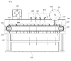
1 is a full perspective view
2 is a cross-sectional view taken along the line A-A '.
Figure 3 is a cross-sectional view taken along line B-B 'showing the overall operation
Hereinafter, exemplary embodiments of the present invention will be described in detail with reference to the accompanying drawings so that those skilled in the art may easily implement the present invention. The present invention may, however, be embodied in many different forms and should not be construed as limited to the embodiments set forth herein. Like parts are designated by like reference numerals throughout the specification.
Vegetable vegetable plant of the present invention as shown in the [Fig. 1] to [3] large installation
First, the installation
And the discharge duct is primarily accommodated in the vegetable roots and washing liquid discharged from the
At this time, the
The
The
The
In addition, the
At this time, the one
In addition, the driven
In addition, the driven
The
First, two
In addition, the
Due to this structure, a discharge gap A for discharging the vegetable root is formed between one end of the
And on the
The
For reference, the
If the drainage hole is not formed in the general conveyor belt structure because the discharge gap (A) is formed between the
The
The vegetable cutting
Among them, the
In addition, the rotating
In addition, the
At this time, the
For reference, the
The
Among them, the washing
And the washing
The lower surface of the washing
In addition, the
Of course, the angle of the
The washing
And as needed, a
In addition, the
The foreign
Therefore, as the
At this time, the drain belt 474a is formed on the blocking
The
In addition, a
The drying
The drying
Mounting table 410 is for the installation of the
And the
The
For reference, one or three or more blowers 4200 may be installed depending on the width of the transfer belt (), and a separate blower duct may be connected to the outlet of the blower () as necessary.
And the
For reference, the compressor can be omitted if only the pumping pressure of the discharge pump can secure the injection pressure of the cleaning liquid.
Hereinafter, the operation of the present embodiment having such a configuration and the unique effects generated in the process will be described.
For reference, the vegetables to be processed in the following description will be limited to spring onions, but the vegetables applied to the present invention are not limited thereto.
As shown in FIG. 2 and FIG. 3, first, a plurality of waves are seated in the space between each
In this state, when the
Therefore, the wave seated between each
At the same time, when the
The cut soy root is cut and falls to the
In this process, when the
In this process, the washing liquid is mixed with the compressed air supplied from the
At this time, since the injection direction of the
If the angle of each
In this manner, various foreign matters and washing liquids dropped into the
At this time, foreign matters are filtered by the blocking
In this state, when the
The washing is completed, the wave is moved to the
The green onion is dried until it is transported to the outside and then cooked after a separate process.
At this time, the conveying
As described above, the present invention has the effect of improving the processing speed as well as the processing speed of a large amount of vegetables as compared to the existing manual work, because the unnecessary cutting and washing and drying of unnecessary parts of the vegetable are continuously performed in one device. Will have
For reference, the present invention can be applied to the processing of fruits as well as vegetables.
Although the preferred embodiments of the present invention have been described in detail above, the scope of the present invention is not limited thereto, and various modifications and improvements of those skilled in the art using the basic concepts defined in the following claims are also within the scope of the present invention. It belongs to.
100: installation body 110: first support frame
120: second support frame 130: support leg
140: discharge duct 142: slope
144: outlet 200: conveyor
210: driving motor 220: driving roller
222: drive sprocket 230: driven roller
232: driven sprocket 240: transfer belt
242: sprocket chain 244: transfer bar
246: partition plate 300: vegetable cutting unit
310: motor 320: rotating plate
330: cutting blade 400: vegetable washing unit
410: washing liquid storage unit 420: washing liquid discharge pipe
422: injection nozzle 424: discharge pump
430: collecting part 440: return pipe
450: return pump 500: drying unit
510: mounting table 520: blower
Claims (12)
A conveyor unit installed on the installation main body and transferring the vegetables on the installation main body,
And the vegetable cutting unit installed on the installation body,
Vegetable washing unit installed on one side of the cutting unit
Vegetable processing apparatus comprising a.
Vegetable processing apparatus further comprises a vegetable drying unit installed in the vegetable wash.
The conveyor unit,
A drive motor installed in the installation main body,
A driving roller installed at one end of the installation main body in a state of being connected to the driving motor and having a driving sprocket formed therein;
A driven roller which is located at the other end of the installation main body and has a driven sprocket formed therein,
It includes a conveying belt wound around the drive roller and the driven roller,
The conveying belt is sprocket chain is wound around the drive sprocket and the driven sprocket and meshed,
Feed rods arranged at intervals along the length of the sprocket chain with ends connected to the sprocket chain
Vegetable processing apparatus comprising a.
Vegetable processing apparatus further comprises a partition plate standing on the transfer bar.
A discharge gap is formed between one side of the conveyor unit and the installation main body,
The cutting unit is a vegetable processing device is provided on the discharge gap.
The cutting unit,
A motor installed in the installation main body,
Cutting blades connected to the motor and moving on the discharge gap
Vegetable processing apparatus comprising a.
The vegetable processing apparatus further comprises a discharge duct positioned below the discharge gap and the inclined surface formed on one side.
The washing unit,
Washing liquid reservoir,
Vegetable processing apparatus further comprises a discharge pipe which is located on the transfer belt in a state connected to the washing liquid storage.
The washing unit further includes a spray nozzle formed in the discharge pipe,
The spray nozzle is a vegetable processing apparatus is formed in a state that the injection port is inclined toward the discharge gap.
A collecting box installed at one side of the discharge duct,
Vegetable processing apparatus further comprises a water return pipe connecting the water collecting container and the sump.
Vegetable processing apparatus further comprises a foreign material filtering portion is installed on the inlet of the reservoir.
The drying unit,
Vegetable blower comprising a blower and a blower duct for inducing a blow flow to the conveyor unit in a state connected to the blower.
Priority Applications (1)
| Application Number | Priority Date | Filing Date | Title |
|---|---|---|---|
| KR1020100075241A KR20120013077A (en) | 2010-08-04 | 2010-08-04 | Processing apparatus for vegetables |
Applications Claiming Priority (1)
| Application Number | Priority Date | Filing Date | Title |
|---|---|---|---|
| KR1020100075241A KR20120013077A (en) | 2010-08-04 | 2010-08-04 | Processing apparatus for vegetables |
Related Child Applications (1)
| Application Number | Title | Priority Date | Filing Date |
|---|---|---|---|
| KR1020120131660A Division KR20130001190A (en) | 2012-11-20 | 2012-11-20 | Processing apparatus for vegetables |
Publications (1)
| Publication Number | Publication Date |
|---|---|
| KR20120013077A true KR20120013077A (en) | 2012-02-14 |
Family
ID=45836756
Family Applications (1)
| Application Number | Title | Priority Date | Filing Date |
|---|---|---|---|
| KR1020100075241A KR20120013077A (en) | 2010-08-04 | 2010-08-04 | Processing apparatus for vegetables |
Country Status (1)
| Country | Link |
|---|---|
| KR (1) | KR20120013077A (en) |
Cited By (9)
| Publication number | Priority date | Publication date | Assignee | Title |
|---|---|---|---|---|
| CN104441010A (en) * | 2013-12-11 | 2015-03-25 | 邱逸奎 | Uncaria cutting method |
| CN104473308A (en) * | 2014-11-14 | 2015-04-01 | 王伟 | Device for cleaning medlar fruits and loading medlar fruits onto curtain |
| KR101523302B1 (en) * | 2014-11-24 | 2015-05-27 | 황토랑양파즙 영농조합법인 | Onions automatic cleaning device |
| CN106388650A (en) * | 2016-11-24 | 2017-02-15 | 郑州中拓知识产权代理有限公司 | Household round fruit high-efficiency cleaning device |
| CN109170968A (en) * | 2018-08-20 | 2019-01-11 | 李翠霞 | A kind of fruits and vegetables equipment |
| CN109170970A (en) * | 2018-09-04 | 2019-01-11 | 赵云红 | A kind of vegetable deep-processing production line and its deep working method |
| CN111802662A (en) * | 2019-04-12 | 2020-10-23 | 北京斋堂生态农业科技有限公司 | Automatic vegetable washing process with better cleaning effect |
| CN111921830A (en) * | 2020-08-05 | 2020-11-13 | 姜蕾蕾 | Edible mushroom direction sorting unit |
| CN114407088A (en) * | 2022-03-03 | 2022-04-29 | 北京润泽润丰应用技术研究院有限公司 | Continuous cutting device |
-
2010
- 2010-08-04 KR KR1020100075241A patent/KR20120013077A/en not_active Application Discontinuation
Cited By (13)
| Publication number | Priority date | Publication date | Assignee | Title |
|---|---|---|---|---|
| CN104441010A (en) * | 2013-12-11 | 2015-03-25 | 邱逸奎 | Uncaria cutting method |
| CN104441010B (en) * | 2013-12-11 | 2016-04-13 | 邱逸奎 | The method of yncaria stem with hooks segment |
| CN104473308A (en) * | 2014-11-14 | 2015-04-01 | 王伟 | Device for cleaning medlar fruits and loading medlar fruits onto curtain |
| KR101523302B1 (en) * | 2014-11-24 | 2015-05-27 | 황토랑양파즙 영농조합법인 | Onions automatic cleaning device |
| CN106388650A (en) * | 2016-11-24 | 2017-02-15 | 郑州中拓知识产权代理有限公司 | Household round fruit high-efficiency cleaning device |
| CN109170968A (en) * | 2018-08-20 | 2019-01-11 | 李翠霞 | A kind of fruits and vegetables equipment |
| CN109170970A (en) * | 2018-09-04 | 2019-01-11 | 赵云红 | A kind of vegetable deep-processing production line and its deep working method |
| CN109170970B (en) * | 2018-09-04 | 2021-05-04 | 湖南插旗菜业有限公司 | Vegetable deep processing line and deep processing method thereof |
| CN111802662A (en) * | 2019-04-12 | 2020-10-23 | 北京斋堂生态农业科技有限公司 | Automatic vegetable washing process with better cleaning effect |
| CN111921830A (en) * | 2020-08-05 | 2020-11-13 | 姜蕾蕾 | Edible mushroom direction sorting unit |
| CN111921830B (en) * | 2020-08-05 | 2021-11-05 | 福州市凯达生态农业有限公司 | Edible mushroom direction sorting unit |
| CN114407088A (en) * | 2022-03-03 | 2022-04-29 | 北京润泽润丰应用技术研究院有限公司 | Continuous cutting device |
| CN114407088B (en) * | 2022-03-03 | 2023-10-20 | 北京润泽润丰应用技术研究院有限公司 | Continuous cutting device |
Similar Documents
| Publication | Publication Date | Title |
|---|---|---|
| KR20120013077A (en) | Processing apparatus for vegetables | |
| KR20130001190A (en) | Processing apparatus for vegetables | |
| KR102143204B1 (en) | Cleaning System of Tray for Anchovy Boiling And Method for Cleaning ray for Anchovy Boiling | |
| CN105381971A (en) | Duck egg washing, screening and air-drying equipment | |
| KR101202947B1 (en) | A vegetables washing device | |
| US8348046B1 (en) | Conveyor belt cleaning assembly | |
| CN111067050A (en) | Complete equipment for processing dried apples | |
| KR20200120117A (en) | A Water saving bulb washer | |
| CN110584165A (en) | Mango automatic slicing dryer | |
| KR100778188B1 (en) | Allium washer | |
| KR20100091874A (en) | Onion peeling-off apparatus | |
| KR100835507B1 (en) | Auto apparatus for peeling a scallion | |
| CN104874562A (en) | Device for simultaneously cleaning and drying multiple grains | |
| CN108887703B (en) | Mushroom cleaning equipment | |
| KR20100006384U (en) | Device for fruit sorting and washing | |
| KR100431665B1 (en) | Device to strip garlic by wet process | |
| JP4711047B2 (en) | Vegetable cleaning equipment | |
| US4821754A (en) | Flitch washer | |
| CN211832709U (en) | Complete equipment for processing dried apples | |
| CN104431847A (en) | Air bubble washing, blanching, selecting and conveying all-in-one machine | |
| KR200422658Y1 (en) | Rice processing system | |
| KR100668769B1 (en) | Drying machine for eating plate and automatic washer using the same | |
| CN210497415U (en) | From meat cutting machine of taking cleaning function | |
| CN111921925A (en) | Cutting device is used in root of kudzu vine processing | |
| CN208300906U (en) | A kind of fruit low damage cleaning device |
Legal Events
| Date | Code | Title | Description |
|---|---|---|---|
| A201 | Request for examination | ||
| E902 | Notification of reason for refusal | ||
| E601 | Decision to refuse application | ||
| A107 | Divisional application of patent | ||
| WITB | Written withdrawal of application |