KR20110108500A - Precast concrete speed beam and constructing method thereof - Google Patents
Precast concrete speed beam and constructing method thereof Download PDFInfo
- Publication number
- KR20110108500A KR20110108500A KR1020100027720A KR20100027720A KR20110108500A KR 20110108500 A KR20110108500 A KR 20110108500A KR 1020100027720 A KR1020100027720 A KR 1020100027720A KR 20100027720 A KR20100027720 A KR 20100027720A KR 20110108500 A KR20110108500 A KR 20110108500A
- Authority
- KR
- South Korea
- Prior art keywords
- road
- precast concrete
- speed
- stepped
- transverse direction
- Prior art date
Links
Images

Classifications
-
- E—FIXED CONSTRUCTIONS
- E01—CONSTRUCTION OF ROADS, RAILWAYS, OR BRIDGES
- E01F—ADDITIONAL WORK, SUCH AS EQUIPPING ROADS OR THE CONSTRUCTION OF PLATFORMS, HELICOPTER LANDING STAGES, SIGNS, SNOW FENCES, OR THE LIKE
- E01F9/00—Arrangement of road signs or traffic signals; Arrangements for enforcing caution
- E01F9/50—Road surface markings; Kerbs or road edgings, specially adapted for alerting road users
- E01F9/529—Road surface markings; Kerbs or road edgings, specially adapted for alerting road users specially adapted for signalling by sound or vibrations, e.g. rumble strips; specially adapted for enforcing reduced speed, e.g. speed bumps
-
- E—FIXED CONSTRUCTIONS
- E01—CONSTRUCTION OF ROADS, RAILWAYS, OR BRIDGES
- E01C—CONSTRUCTION OF, OR SURFACES FOR, ROADS, SPORTS GROUNDS, OR THE LIKE; MACHINES OR AUXILIARY TOOLS FOR CONSTRUCTION OR REPAIR
- E01C5/00—Pavings made of prefabricated single units
- E01C5/005—Individual couplings or spacer elements for joining the prefabricated units
- E01C5/006—Individual spacer elements
-
- E—FIXED CONSTRUCTIONS
- E01—CONSTRUCTION OF ROADS, RAILWAYS, OR BRIDGES
- E01C—CONSTRUCTION OF, OR SURFACES FOR, ROADS, SPORTS GROUNDS, OR THE LIKE; MACHINES OR AUXILIARY TOOLS FOR CONSTRUCTION OR REPAIR
- E01C5/00—Pavings made of prefabricated single units
- E01C5/06—Pavings made of prefabricated single units made of units with cement or like binders
Landscapes
- Engineering & Computer Science (AREA)
- Architecture (AREA)
- Civil Engineering (AREA)
- Structural Engineering (AREA)
- Road Signs Or Road Markings (AREA)
- Road Paving Structures (AREA)
Abstract
본 발명에서는 차량의 속도 감속을 유도하는 과속방지턱을 도로에 시공하는 방법으로서, 두께를 가지는 판형상 프리캐스트 콘크리트 부재로 이루어지되, 종방향의 양측에는 계단형상의 단턱이 횡방향으로 연장되도록 형성되어 있는 단턱부(11)가 종방향 가장자리에 형성되고, 상기 단턱부(11) 사이는 판의 원래 두께를 유지하는 중앙부(12)가 횡방향으로 연장되어 형성되며, 상기 중앙부(12)에는 도로포장의 표면 위로 볼록하게 돌출되거나 또는 오목하게 파여 있는 요철부(13)가 중앙부(12)의 표면에서 횡방향으로 연장 형성되어 있는 구조를 가지고 있는 매립형 프리캐스트 콘크리트 과속방지턱 구조물(1)을 도로를 가로질러 배치하고; 도로포장재가 상기 단턱부(11)의 윗면에 덮어씌워지고 상기 중앙부(12)의 표면은 외부에 노출되는 형태로, 도로포장 작업을 수행하여 상기 매립형 프리캐스트 콘크리트 과속방지턱 구조물(1)이 도로포장재 내에 매립되어 설치되도록 하는 것을 특징으로 하는 도로의 과속방지턱 시공방법과, 이를 위한 매립형 프리캐스트 콘크리트 과속방지턱 구조물이 제공된다. In the present invention, as a method of constructing the speed bumps to induce the speed reduction of the vehicle on the road, it is made of a plate-shaped precast concrete member having a thickness, the stepped stepped in both sides in the longitudinal direction is formed to extend in the transverse direction The stepped part 11 is formed at the longitudinal edge, and the stepped part 11 is formed between the central part 12 which maintains the original thickness of the plate and extends laterally, and the central part 12 is paved with roads. Concave or convex protrusions 13 protrudingly concave or concave over the surface of the buried precast concrete speed bump structure 1 having a structure extending from the surface of the central portion 12 across the road To place; The road paving material is covered with the upper surface of the stepped portion 11 and the surface of the central portion 12 is exposed to the outside, the road-prepared precast concrete speed bumps structure (1) is a road paving material There is provided a speed bump construction method of a road, characterized in that the installation is embedded in, and a buried precast concrete speed bump structure for this.
Description
본 발명은 매립형 프리캐스트 콘크리트 과속방지턱 구조물 및 이를 이용한 과속방지턱 시공방법에 관한 것으로서, 구체적으로는 도로에 설치되어 도로 표면에 굴곡이 형성되어 있어 차량이 주행속도를 줄이도록 유도하는 과속방지턱을 구성하고 이를 시공함에 있어서, 프리캐스트 콘크리트로 제작하여 아스팔트 도로포장 또는 콘크리트 도로포장의 포설시에 도로포장재 내에 일체로 매립되도록 함으로써, 차량의 과속방지를 유도하면서도 내구성과 안정성을 높일 수 있도록 구성한 매립형 프리캐스트 콘크리트 과속방지턱 구조물과, 이를 이용하여 과속방지턱을 시공하는 방법에 관한 것이다.
The present invention relates to a buried precast concrete speed bump construction and a speed bump construction method using the same. Specifically, the speed bump is installed on the road to form a bend on the road surface to guide the vehicle to reduce the traveling speed. In this construction, the pre-cast concrete is made of precast concrete to be embedded in the road paving material when paving the asphalt road paving or concrete road paving, to induce speeding prevention of the vehicle and to increase durability and stability. The speed bumps structure and a method for constructing the speed bumps using the same.
도로 횡단이 빈번한 지역이나, 횡단보도 부근, 아파트 진입로 입구 등에는 차량이 주행속도를 줄이도록 유도하기 위하여 과속방지턱이 설치된다. 종래의 과속방지턱은 아스팔트 도로포장의 두께를 두껍게 하거나, 합성수지재로 만들어진 것을 앵커볼트 등으로 도로포장재 표면에 결합 설치하는 방식으로 이루어져 있다. 그런데, 아스팔트 도로포장을 두껍게 하여 과속방지턱을 설치하는 경우, 곡선형 상면이 되도록 과속방지턱을 만드는 작업이 도로포장재의 포설 현장에서 이루어지므로, 현장 작업자의 숙련도에만 의지하여 눈대중으로 대강 만들어지고 있는 실정이다. 따라서 과속방지턱의 돌출 높이, 폭, 형상 등이 일정하지 못하게 되고, 어떤 경우에는 심하게 돌출되어 차량 하부에 손상을 주거나 또는 너무 돌출되지 아니하여 차량속도 감속 유도 효과가 미미하게 되는 경우가 발생하게 된다. Speed bumps are installed in areas where road crossings are frequent, near pedestrian crossings, and entrances to apartments to reduce the speed of the vehicle. Conventional speed bumps are made of thickening the asphalt road pavement, or made of synthetic resin material by coupling to the road pavement surface, such as anchor bolts. By the way, when the speed bumps are installed by thickening the asphalt road pavement, the speed bumps are made at the site of the road paving material so that the speed bumps are curved, so that they are largely made into the snow masses based only on the proficiency of the site workers. . Therefore, the protruding height, width, shape, etc. of the speed bumps are not constant, and in some cases, protruding severely may damage the lower part of the vehicle or may not protrude too much, resulting in inefficient vehicle speed reduction induction.
또한 아스팔트를 평평하게 포설하고 다짐이 완료되어 도로포장재의 포설이 완전히 이루어진 후에, 별도로 아스팔트를 도로포장의 표면에 덧씌워 과속방지턱을 형성하는 경우가 많은데, 이 경우, 도로포장과 과속방지턱이 일체화되지 못하여 파손의 문제가 발생하게 된다. 차량이 과속방지턱을 넘어서 주행할 때, 필연적으로 과속방지턱에는 수평방향의 힘(수평력)이 작용하게 되는데, 위와 같이 도로포장과 과속방지턱이 일체화되지 못한 경우에는 차량 주행시 발생하는 수평력에 의해, 도로포장과 과속방지턱 사이에 전단파괴가 발생하여 과속방지턱이 도로포장으로부터 분리되어 탈락되는 지는 현상이 발생하는 등, 내구성과 안전성에 있어서 매우 취약함을 가지게 된다. In addition, after the asphalt is laid flat and compaction is completed, the road paving material is completely laid, and the asphalt bump is often overlaid on the surface of the road pavement to form a speed bump, in which case the road pavement and the speed bump are not integrated. The problem of breakage occurs. When the vehicle travels over the speed bump, a horizontal force (horizontal force) is inevitably applied to the speed bump, and when the road pavement and the speed bump are not integrated as described above, the road is paved by the horizontal force generated when driving the vehicle. Shear failure occurs between the overspeed bumps and the speed bumps are separated from the road pavement, which causes the phenomenon of being extremely weak in durability and safety.
과속방지턱을 합성수지재로 만들어서 앵커볼트 등을 이용하여 도로포장의 표면에 고정 설치하는 경우에도, 내구성과 안전성에 취약하다는 단점이 있다. 즉, 도로포장과 다른 재료로 만들어진 과속방지턱이 단순히 앵커볼트 등에 의해서만 도로포장에 결합되어 있으므로, 차량 주행으로 인한 수평력에 대해 취약할 수밖에 없다. 특히 차량 주행시에는 수평력 이외에도 진동하중이 지속적으로 과속방지턱에 가해지게 되는데, 이러한 진동하중으로 인하여 앵커볼트의 체결이 느슨하게 되는 등의 현상이 발생하게 되고, 그에 따라 과속방지턱 전체가 도로포장으로부터 분리되는 상황도 빈번하게 발생한다. 이러한 이유 때문에 합성수지재로 만들어진 과속방지턱은 건물의 입구, 아파트 도로 입구 등과 같이 차량 통행이 적은 소규모 도로에서만 지엽적으로 사용되고 있을 뿐이며, 실제 주행로에는 사용되지 못하고 있는 실정이다.
Even when the speed bumps are made of synthetic resin and fixedly installed on the surface of the road pavement using anchor bolts, there is a disadvantage that they are vulnerable to durability and safety. That is, since the speed bumps made of the road pavement and other materials are coupled to the pavement only by anchor bolts, etc., there is no choice but to be vulnerable to the horizontal force caused by the vehicle driving. In particular, when the vehicle is driven, vibration loads are continuously applied to the speed bumps in addition to the horizontal force. Such vibration loads cause loosening of anchor bolts, and thus the entire speed bumps are separated from the pavement. It also occurs frequently. For this reason, the speed bumps made of synthetic resin are only used locally on small roads, such as building entrances and apartment road entrances, and are not used in actual driving paths.
본 발명은 위와 같은 문제점을 해소하기 위하여 개발된 것으로서, 차량이 주행속도를 줄이도록 유도하기 위하여 설치되는 과속방지턱을 구성하고 시공함에 있어서, 규격화가 용이하며, 도로포장과 과속방지턱이 견고하게 일체화될 수 있도록 하여 차량 주행에 의해 발생하는 수평력 및 진동하중에 대해서 안정적이며 우수한 내구성을 가지도록 함으로써, 소규모의 도로뿐만 아니라 주행로에도 사용하기에 적합한 새로운 과속방지턱 구조물과 이를 시공하는 방법을 제공하는 것을 목적으로 한다.
The present invention has been developed to solve the above problems, in the construction and construction of the speed bumps installed to guide the vehicle to reduce the running speed, it is easy to standardize, and the road pavement and speed bumps are firmly integrated. The purpose of this invention is to provide a new speed bump structure suitable for use on roads as well as small roads, and a method of constructing the same, by providing stable and excellent durability against horizontal forces and vibration loads generated by vehicle driving. It is done.
본 발명에서는 위와 같은 목적을 달성하기 위하여, 매립형 프리캐스트 콘크리트 과속방지턱 구조물(이하, "과속방지턱 구조물"이라고 약칭한다)이 제공되는데, 본 발명의 과속방지턱 구조물은, 두께를 가지는 판형상 프리캐스트 콘크리트 부재로 이루어지되; 종방향의 양측에는 계단형상의 단턱이 횡방향으로 연장되도록 형성되어 있어, 원래의 판두께보다 얇아져 있으며, 도로에 배치되었을 때 도로포장재가 위에 덮여 도로포장재에 매립되는 단턱부가 종방향 가장자리에 형성되고; 상기 단턱부 사이는 판의 원래 두께를 유지하며 도로포장재에 매립되었을 때 표면이 외부에 노출되는 중앙부가 횡방향으로 연장되어 형성되며; 상기 중앙부에는 도로포장의 표면 위로 볼록하게 돌출되거나 또는 오목하게 파여 있는 요철부가 중앙부의 표면에서 횡방향으로 연장 형성되어 있는 구조를 가지고 있어, 도로포장재 내에 매립되어 설치되어 차량의 속도 감속을 유도하게 되는 것을 특징으로 한다. In the present invention, in order to achieve the above object, a buried precast concrete speed bump structure (hereinafter abbreviated as "speed bump structure") is provided, the speed bump structure of the present invention, plate-shaped precast concrete having a thickness Consist of absence; On both sides of the longitudinal direction, the stepped stepped jaw is formed to extend in the transverse direction, which is thinner than the original plate thickness, and when placed on the road, the stepped portion covered with the road paving material is embedded on the road paving material and formed at the longitudinal edge. ; Between the stepped portions is formed to maintain the original thickness of the plate extends in the transverse direction the central portion exposed to the outside when embedded in the road paving material; The central portion has a structure in which convex and convex protrusions or concave portions which are convexly protruded over the surface of the road pavement extend laterally from the surface of the central pavement, and are embedded in the pavement material to induce a speed reduction of the vehicle. It is characterized by.
위와 같은 본 발명에 있어서, 요철부는, 중앙부의 표면 위로 볼록하게 돌출되어 있는 볼록부로 형성되거나, 중앙부의 표면에서 두께 방향으로 오목하게 파인 오목부로 형성될 수 있다. In the present invention as described above, the uneven portion may be formed as a convex portion protruding convexly on the surface of the center portion, or may be formed as a concave portion recessed in the thickness direction on the surface of the center portion.
또한 위와 같은 본 발명의 과속방지턱 구조물내에는, 복수개가 횡방향으로 연속 배치되었을 때, 긴장재를 복수개의 과속방지턱 구조물에 관통 배치하여 횡방향으로 긴장력을 부여할 수 있도록, 긴장재가 배치되거나, 또는 횡방향으로 놓인 복수개의 과속방지턱 구조물을 관통하여 철근이 배치되고 채움재가 채워질 수 있는 횡방향의 관통공이 형성될 수 있다. In addition, in the speed bumps structure of the present invention as described above, when the plurality is continuously disposed in the transverse direction, the tension member is disposed so as to penetrate the plurality of speed bumps structure through the plurality of speed bumps structure to impart a tension force in the transverse direction, or transverse A transverse through hole may be formed through which the rebar may be disposed and the filler may be filled through the plurality of speed bumps arranged in the direction.
한편, 본 발명에서는 위와 같은 과속방지턱 구조물을 도로에 설치하여 과속방지턱을 시공하는 방법이 제공되는데, 구체적으로 본 발명에서는 상기한 과속방지턱 구조물을 도로를 가로질러 배치하고; 도로포장재가 상기 단턱부(11)의 윗면에 덮어씌워지고 상기 중앙부의 표면은 외부에 노출되는 형태로, 도로포장 작업을 수행하여 상기 과속방지턱 구조물이 도로포장재 내에 매립되어 설치되도록 하는 것을 특징으로 하는 도로의 과속방지턱 시공방법이 제공된다. On the other hand, the present invention provides a method for constructing the speed bumps by installing the speed bumps on the road as described above, specifically, the speed bumps structure is disposed across the road; The road paving material is covered with the upper surface of the
이와 같은 본 발명의 시공방법에서, 상기 과속방지턱 구조물에 횡방향 관통공을 형성하고; 상기 과속방지턱 구조물을 도로에 배치할 때, 복수개를 횡방향으로 연속하여 배치한 후, 상기 횡방향 관통공 내에 긴장재를 배치하여 횡방향으로 긴장력을 부여하거나, 또는 상기 횡방향 관통공 내에 철근을 관통 배치하고 관통공에 채움재를 채워 경화시킴으로써 서로 일체화시킬 수 있다.
In the construction method of the present invention as described above, forming a transverse through hole in the speed bumps structure; When arranging the speed bump structure on the road, after placing the plurality in succession in the transverse direction, the tension member is disposed in the transverse through hole to impart a tension force in the transverse direction, or penetrate the reinforcing bar in the transverse through hole. It can be integrated with each other by arranging and filling a through-hole with a filler.
본 발명에 의하면, 단턱부가 도로포장재 내부에 매립되고 과속방지턱 구조물의 양측면이 도로포장재에 의해 구속되어 있는 형태로 과속방지턱 구조물이 도로에 매립되어 설치되므로, 차량 주행으로 인하여 발생하는 수평력이 과속방지턱 구조물에 가해지더라도 과속방지턱 자체가 도로포장과 분리되거나, 과속방지턱과 도로포장 사이의 결합이 훼손되는 현상이 발생하지 않게 되어 안정성과 내구성이 현저하게 개선되는 효과가 발휘된다. 특히, 차량의 바퀴와 직접 충돌하게 되는 요철부가 중앙부와 일체화되어 있기 때문에 요철부만이 분리되는 현상이 발생하지 않게 된다. According to the present invention, since the speed bumps are buried in the road in a form in which the stepped parts are embedded in the road pavement and both sides of the speed bumps are restrained by the road pavement, the horizontal force generated by the vehicle driving is caused by the speed bumps. Even if it is applied to the speed bumps are not separated from the road pavement itself, or the coupling between the speed bumps and the road pavement does not occur, the stability and durability is remarkably improved. In particular, since the uneven portion which directly collides with the wheel of the vehicle is integrated with the center portion, only the uneven portion is separated.
일반적으로 과속방지턱의 표면에는 용이한 식별을 위해 무늬를 색칠하게 되는데, 본 발명에서는 과속방지턱이 프리캐스트 콘크리트 부재로 사전 제작되므로, 과속방지턱의 생산시에 콘크리트에 안료 등을 첨가하여 필요한 색을 용이하게 가지도록 할 수 있으므로, 사용자에게 쉽게 눈에 띌 수 있는 색을 가지도록 과속방지턱을 용이하게 생산할 수 있게 된다. In general, the surface of the speed bump is painted with a pattern for easy identification. In the present invention, the speed bump is prefabricated with a precast concrete member. Since it can be made so that the speed bumps can be easily produced to have a color that is easily visible to the user.
또한, 과속방지턱 구조물이 프리캐스트 부재로 사전 제작되어 설치되므로, 그 형상과 크기가 균일해지며 표준화시킬 수 있게 되는 효과가 발휘된다.
In addition, since the speed bump member is prefabricated and installed as a precast member, the shape and size are uniform and the effect of being able to standardize is exhibited.
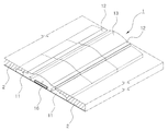
도 1은 본 발명의 일실시예에 따른 과속방지턱 구조물의 개략적인 사시도이다.
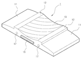
도 2는 도 1에 도시된 실시예의 과속방지턱 구조물이 도로의 횡방향으로 복수개로 일체 연결되어 도로에 매립 설치되어 있는 상태의 개략적인 사시도이다.
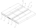
도 3 및 도 4는 각각 도 1 및 도 2에 대응되는 도면으로서, 본 발명의 또다른 실시예로서 요철부가 오목부로 형성된 과속방지턱 구조물에 대한 사시도이다. 1 is a schematic perspective view of a speed bump structure according to an embodiment of the present invention.
2 is a schematic perspective view of a state in which the speed bump member of the embodiment illustrated in FIG. 1 is integrally connected to a plurality of roads in a transverse direction of a road and embedded in a road;
3 and 4 are views corresponding to FIGS. 1 and 2, respectively, and are perspective views of a speed bump structure having recesses and protrusions as another embodiment of the present invention.
이하, 첨부도면을 참조하면서 본 발명의 바람직한 실시예를 더욱 구체적으로 설명한다. 본 발명은 도면에 도시된 실시예를 참고로 설명되었으나 이는 하나의 실시예로서 설명되는 것이며 이것에 의해 본 발명의 기술적 사상과 그 핵심 구성 및 작용이 제한되지 않는다. Hereinafter, preferred embodiments of the present invention will be described in more detail with reference to the accompanying drawings. The present invention has been described with reference to the embodiments shown in the drawings, which are described as one embodiment by which the technical spirit of the present invention and its core configuration and operation are not limited.
도 1에는 본 발명의 일실시예에 따른 매립형 프리캐스트 콘크리트 과속방지턱 구조물(1)("과속방지턱 구조물")의 개략적인 사시도가 도시되어 있고, 도 2에는 도 1에 도시된 실시예의 과속방지턱 구조물(1)이 도로의 횡방향으로 복수개로 일체 연결되어 도로에 매립 설치되어 있는 상태의 개략적인 사시도가 도시되어 있다. 1 is a schematic perspective view of a buried precast concrete speed bump structure 1 ("speed bump structure") according to an embodiment of the present invention, Figure 2 is a speed bump structure of the embodiment shown in FIG. A schematic perspective view of a state in which (1) is integrally connected in plurality in the transverse direction of the road and embedded in the road is shown.
도면에 도시된 것처럼, 본 발명의 과속방지턱 구조물(1)은 두께를 가지는 판형상 프리캐스트 콘크리트 부재로 이루어지는데, 종방향(차량 주행방향)의 양측에는 계단형상의 단턱이 횡방향으로 연장되도록 형성되어 있어, 원래의 판두께보다 얇아진 단턱부(11)가 가장자리에 형성되고, 상기 단턱부(11) 사이는 판의 원래 두께를 유지하는 중앙부(12)가 횡방향으로 연장되어 형성되며, 상기 중앙부(12)에는 도로포장의 표면 위로 볼록하게 돌출되거나 또는 오목하게 파이는 요철부(13)가 중앙부(12)의 표면에서 횡방향으로 연장 형성되어 있는 구조와 형상을 가진다. As shown in the figure, the speed bumps structure 1 of the present invention is made of a plate-shaped precast concrete member having a thickness, formed on both sides of the longitudinal direction (vehicle driving direction) so that the stepped stepped in the transverse direction The stepped
원래 판두께보다 얇은 상기 단턱부(11)는 과속방지턱 구조물(1)이 도로에 배치되었을 때 도로포장재가 그 위에 덮여 도로포장재에 매립되며, 단턱부(11) 사이에 존재하는 중앙부(12)의 표면은 외부에 노출되어 도로 표면의 일부가 된다. 상기 중앙부(12)의 상면에는 요철부(13)가 형성되는데, 도 1 및 도 2에 도시된 실시예에서는 상기 요철부(13)가, 볼록하게 돌출되어 있는 볼록부로 형성되어 중앙부(12)의 가운데에 형성되어 있다. 요철부(13)가 볼록부로 형성되는 경우, 상기 볼록부의 상면은 차량의 손상을 방지하고, 차량이 부드럽게 타넘어 가도록 하기 위하여 곡면으로 이루어지는 것이 바람직하다. 또한 요철부(13)가 볼록부로 형성되는 경우, 볼록부의 표면에는 마찰력 증대를 위한 무늬가 형성되는 것이 바람직하다. The stepped
도 3 및 도 4에는 각각 도 1 및 도 2에 대응되는 본 발명의 또다른 실시예로서 요철부(13)가 오목부로 형성된 실시예에 대한 사시도가 도시되어 있다. 도 3 및 도 4에 도시된 것처럼, 상기 요철부(13)는 중앙부(12)의 표면에서 두께 방향으로 오목하게 파인 오목부로 형성될 수 있다. 이 경우 차량 충격을 방지하도록 볼록부와 마찬가지로 오목부의 내면은 곡면으로 이루어지는 것이 바람직하며, 오목부의 표면에도 무늬가 형성될 수 있다. 3 and 4 are perspective views of an embodiment in which the
도면에 도시된 것처럼, 본 발명에 따른 과속방지턱 구조물(1)은 도로포장재에 매립되어 설치된다. 즉, 도로포장재(2)가 포설되기 전에 또는 도로포장재(2)의 일부가 포설된 상태에서, 과속방지턱 구조물(1)이 배치되고, 상기 단턱부(11)가 도로포장재에 매립되도록 과속방지턱 구조물(1)의 종방향 양측으로 도로포설 작업이 이루어져 도로포장재(2)가 상기 단턱부(11)의 측면 및 상면 위를 덮게 된다. 이 때, 도로포장재(2)는 단턱부(11) 사이의 중앙부(12) 높이까지만 포설되는 것이 바람직하며, 그에 따라 중앙부(12)의 상면은 그대로 외부에 노출되고, 중앙부(12)의 상면과 도로포장재(2)의 상면을 동일한 높이로 이어지게 된다. As shown in the figure, the speed bumps structure 1 according to the present invention is installed embedded in the road paving material. That is, before the
이와 같이, 본 발명에 따른 과속방지턱 구조물(1)은 단턱부(11)가 도로포장재(2) 내부에 매립되고 과속방지턱 구조물(1)의 양측면이 도로포장재(2)에 의해 구속되어 있는 형태로 설치되므로, 차량 주행으로 인하여 발생하는 수평력이 과속방지턱 구조물(1)에 가해지더라도 과속방지턱 자체가 도로포장과 분리되거나, 과속방지턱과 도로포장 사이의 결합이 훼손되는 현상이 발생하지 않게 되어 안정성과 내구성이 현저하게 개선되는 효과가 발휘된다. 특히, 차량의 바퀴와 직접 충돌하게 되는 요철부(13)가 중앙부(12)와 일체화되어 있기 때문에 요철부(13)만이 분리되는 현상이 발생하지 않게 된다. As such, the speed bumps structure 1 according to the present invention has a step in which the stepped
일반적으로 과속방지턱의 표면에는 용이한 식별을 위해 무늬를 색칠하게 되는데, 본 발명에서는 과속방지턱이 프리캐스트 콘크리트 부재로 사전 제작되므로, 과속방지턱 구조물의 생산시에 콘크리트에 안료 등을 첨가하여 필요한 색을 용이하게 가지도록 할 수 있으므로, 사용자에게 쉽게 눈에 띌 수 있는 색을 가지도록 과속방지턱 구조물을 용이하게 생산할 수 있게 된다. In general, the surface of the speed bumps is painted with a pattern for easy identification. In the present invention, the speed bumps are prefabricated with precast concrete members, so that pigments are added to the concrete to produce the required color when the speed bumps are produced. Since it can be easily to have, it is possible to easily produce the speed bump structure to have a color that is easily visible to the user.
한편, 본 발명의 과속방지턱 구조물(1)은 도로의 횡방향(도로의 폭 방향)으로 복수개가 조립 연결되어 도로에 설치될 수 있다. 즉, 운반이나 취급이 용이한 횡방향 길이로 제작한 후, 현장에서 도로의 폭에 맞추어 복수개를 일체 결합하여 설치할 수 있는 것이다. 이 경우, 과속방지턱 구조물(1)의 횡방향 체결을 위하여 도 1 및 도 3에 도시된 것처럼, 과속방지턱 구조물(1)의 횡방향 측면에 전단키(16)를 형성하여, 전단키 결합이 이루어지도록 할 수 있다. On the other hand, the speed bumps structure 1 of the present invention may be installed on the road by assembling a plurality in the transverse direction (road width direction of the road) of the road. That is, after manufacturing to the transverse length which is easy to carry or handle, it can install by combining several pieces together according to the width of the road in the field. In this case, as illustrated in FIGS. 1 and 3, the
또한 필요에 따라서는 과속방지턱 구조물(1)의 횡방향으로 관통공(17)을 형성하여 횡방향으로 연속 배치된 과속방지턱 구조물(1)들을 관통하도록 강선과 같은 긴장재를 배치하여 긴장력을 부여하여 횡방향으로 서로 일체화시킬 수도 있다. 또한, 도면에는 도시되지 아니하였지만, 상기 관통공(17) 또는 이와는 별도로 횡방향으로 형성된 관통공(도면에 도시되지 않음)에, 횡방향으로 연속 배치된 과속방지턱 구조물(1)들을 관통하도록 철근을 배치하고 관통공에 무수축 모르타르와 같은 채움재를 주입하여 경화시켜 횡방향의 일체화를 도모할 수도 있고, 기타 아이볼트를 이용한 결합 등과 같이 종래의 프리캐스트 콘크리트 부재 간의 접합 기술을 이용하여 횡방향으로 배치된 복수개의 과속방지턱 구조물(1)을 일체로 결합할 수도 있다. In addition, if necessary, forming a through-
한편, 복수개의 과속방지턱 구조물(1)을 횡방향으로 연속 배치 및 결합하는 구성에서는, 도면에 예시된 것처럼, 요철부(13)의 표면 무늬를 각 과속방지턱 구조물(1) 마다 달리하는 것도 바람직하다.
On the other hand, in the configuration of continuously arranging and coupling the plurality of speed bumps structures 1 in the lateral direction, it is also preferable to vary the surface pattern of the
1 : 매립형 프리캐스트 콘크리트 과속방지턱(매립형 과속방지턱)
11 : 단턱부
12 : 중앙부
13 : 요철부
1: buried precast concrete speed bumps (buried speed bumps)
11: step
12: center part
13: uneven portion
Claims (7)
종방향의 양측에는 계단형상의 단턱이 횡방향으로 연장되도록 형성되어 있어, 원래의 판두께보다 얇아져 있으며, 도로에 배치되었을 때 도로포장재가 위에 덮여 도로포장재에 매립되는 단턱부(11)가 종방향 가장자리에 형성되고;
상기 단턱부(11) 사이는 판의 원래 두께를 유지하며 도로포장재에 매립되었을 때 표면이 외부에 노출되는 중앙부(12)가 횡방향으로 연장되어 형성되며;
상기 중앙부(12)에는 도로포장의 표면 위로 볼록하게 돌출되거나 또는 오목하게 파여 있는 요철부(13)가 중앙부(12)의 표면에서 횡방향으로 연장 형성되어 있는 구조를 가지고 있어, 도로포장재 내에 매립되어 설치되어 차량의 속도 감속을 유도하게 되는 것을 특징으로 하는 매립형 프리캐스트 콘크리트 과속방지턱 구조물.
Consisting of a plate-shaped precast concrete member having a thickness;
On both sides of the longitudinal direction, the stepped stepped jaw is formed to extend in the transverse direction, which is thinner than the original plate thickness, and when placed on the road, the stepped portion 11 embedded in the road paving material is covered with the road paving material on the road. Formed at the edge;
Between the stepped portions (11) is formed to maintain the original thickness of the plate and the center portion (12) extending in the transverse direction when the surface is exposed to the outside when embedded in the road paving material;
The central portion 12 has a structure in which the convex and convex portions 13 which protrude convexly or concavely over the surface of the road pavement extend laterally from the surface of the central part 12 and are embedded in the road pavement material. A buried precast concrete speed bump structure, characterized in that it is installed to induce a speed reduction of the vehicle.
상기 요철부(13)는, 중앙부(12)의 표면 위로 볼록하게 돌출되어 있는 볼록부로 형성되어 있는 것을 특징으로 하는 매립형 프리캐스트 콘크리트 과속방지턱 구조물.
The method of claim 1,
The uneven part 13 is a buried precast concrete speed bump structure, characterized in that formed by a convex portion protruding convexly on the surface of the central portion (12).
상기 요철부(13)는, 중앙부(12)의 표면에서 두께 방향으로 오목하게 파인 오목부로 형성되어 있는 것을 특징으로 하는 매립형 프리캐스트 콘크리트 과속방지턱 구조물.
The method of claim 1,
The concave-convex portion 13 is a buried precast concrete speed bump structure, characterized in that formed in the concave portion recessed in the thickness direction on the surface of the central portion (12).
과속방지턱 구조물(1) 내에는, 복수개의 과속방지턱 구조물(1)이 횡방향으로 연속 배치되었을 때, 복수개의 과속방지턱 구조물(1)에 긴장재가 관통 배치되어 횡방향으로 긴장력을 부여할 수 있도록 또는 횡방향으로 놓인 복수개의 과속방지턱 구조물(1)을 관통하여 철근이 배치되고 채움재가 채워질 수 있는, 횡방향의 관통공이 형성되어 있는 것을 특징으로 하는 매립형 프리캐스트 콘크리트 과속방지턱 구조물.
4. The method according to any one of claims 1 to 3,
In the speed bumps structure 1, when the plurality of speed bumps structure 1 is continuously disposed in the transverse direction, the tension member is penetrated through the plurality of speed bumps structure 1 to impart tension in the transverse direction or A buried precast concrete speed bump structure, characterized in that a transverse through-hole is formed through which a plurality of speed bump members (1) placed in the transverse direction can be disposed and the filling material can be filled.
두께를 가지는 판형상 프리캐스트 콘크리트 부재로 이루어지되, 종방향의 양측에는 계단형상의 단턱이 횡방향으로 연장되도록 형성되어 있는 단턱부(11)가 종방향 가장자리에 형성되고, 상기 단턱부(11) 사이는 판의 원래 두께를 유지하는 중앙부(12)가 횡방향으로 연장되어 형성되며, 상기 중앙부(12)에는 도로포장의 표면 위로 볼록하게 돌출되거나 또는 오목하게 파여 있는 요철부(13)가 중앙부(12)의 표면에서 횡방향으로 연장 형성되어 있는 구조를 가지고 있는 매립형 프리캐스트 콘크리트 과속방지턱 구조물(1)을 도로를 가로질러 배치하고;
도로포장재가 상기 단턱부(11)의 윗면에 덮어씌워지고 상기 중앙부(12)의 표면은 외부에 노출되는 형태로, 도로포장 작업을 수행하여 상기 매립형 프리캐스트 콘크리트 과속방지턱 구조물(1)이 도로포장재 내에 매립되어 설치되도록 하는 것을 특징으로 하는 도로의 과속방지턱 시공방법.
As a method of constructing a speed bump on the road to induce a speed reduction of the vehicle,
It is made of a plate-shaped precast concrete member having a thickness, but on both sides in the longitudinal direction stepped portion 11 is formed in the longitudinal edge is formed so that the stepped stepped in the transverse direction, the stepped portion 11 Between the center portion 12, which maintains the original thickness of the plate is formed extending in the transverse direction, the central portion 12 has a convex protrusion 13, which protrudes convexly or concavely over the surface of the road pavement, the center portion ( 12. A buried precast concrete speed bumps structure 1 having a structure extending laterally from the surface of 12) is disposed across the roadway;
The road paving material is covered with the upper surface of the stepped portion 11 and the surface of the central portion 12 is exposed to the outside, the road-prepared precast concrete speed bumps structure (1) is a road paving material Speed bump construction method of the road, characterized in that the buried in the installation.
상기 매립형 프리캐스트 콘크리트 과속방지턱 구조물(1)에는, 횡방향 관통공이 형성되어 있으며;
상기 매립형 프리캐스트 콘크리트 과속방지턱 구조물(1)을 도로에 배치할 때, 복수개를 횡방향으로 연속하여 배치한 후, 상기 횡방향 관통공 내에 긴장재를 배치하여 횡방향으로 긴장력을 부여하여 서로 일체화시키는 것을 특징으로 하는 도로의 과속방지턱 시공방법.
The method of claim 5,
The buried precast concrete speed bumps structure (1) is formed with a transverse through hole;
When arranging the buried precast concrete speed bumps structure (1) on the road, and after placing a plurality in succession in the transverse direction, by placing a tension member in the transverse through-hole to give tension in the transverse direction to integrate with each other Speed bump construction method of the road characterized in that.
상기 매립형 프리캐스트 콘크리트 과속방지턱 구조물(1)에는, 횡방향 관통공이 형성되어 있으며;
상기 매립형 프리캐스트 콘크리트 과속방지턱 구조물(1)을 도로에 배치할 때, 복수개를 횡방향으로 연속하여 배치한 후, 상기 횡방향 관통공 내에 철근을 관통 배치하고 관통공에 채움재를 채워 경화시킴으로써 서로 일체화시키는 것을 특징으로 하는 도로의 과속방지턱 시공방법.
The method of claim 5,
The buried precast concrete speed bumps structure (1) is formed with a transverse through hole;
When the buried precast concrete speed bumps structure 1 is disposed on the road, the plurality of the precast concrete speed bumps 1 are continuously arranged in the transverse direction, and then the reinforcing precast concrete speed bumps are integrated into the transverse through-holes by placing reinforcing bars and filling the through-holes with hardening material. Speed bump construction method of the road, characterized in that.
Priority Applications (1)
| Application Number | Priority Date | Filing Date | Title |
|---|---|---|---|
| KR1020100027720A KR101185468B1 (en) | 2010-03-29 | 2010-03-29 | Precast Concrete Speed Beam and Constructing Method thereof |
Applications Claiming Priority (1)
| Application Number | Priority Date | Filing Date | Title |
|---|---|---|---|
| KR1020100027720A KR101185468B1 (en) | 2010-03-29 | 2010-03-29 | Precast Concrete Speed Beam and Constructing Method thereof |
Publications (2)
| Publication Number | Publication Date |
|---|---|
| KR20110108500A true KR20110108500A (en) | 2011-10-06 |
| KR101185468B1 KR101185468B1 (en) | 2012-10-02 |
Family
ID=45026070
Family Applications (1)
| Application Number | Title | Priority Date | Filing Date |
|---|---|---|---|
| KR1020100027720A KR101185468B1 (en) | 2010-03-29 | 2010-03-29 | Precast Concrete Speed Beam and Constructing Method thereof |
Country Status (1)
| Country | Link |
|---|---|
| KR (1) | KR101185468B1 (en) |
Cited By (4)
| Publication number | Priority date | Publication date | Assignee | Title |
|---|---|---|---|---|
| CN106638349A (en) * | 2016-11-25 | 2017-05-10 | 辽宁虹圆现代农业装备技术开发有限公司 | Convex-concave type decelerator with steel plates |
| KR102124528B1 (en) * | 2020-02-21 | 2020-06-18 | 주식회사 수성씨에프 | S-curved prefabricated speed bump block with excellent durability, and manufacturing method thereof |
| CN113622257A (en) * | 2021-07-16 | 2021-11-09 | 朱学军 | Rural highway road surface structure of economical and applicable type |
| KR102508397B1 (en) * | 2022-08-31 | 2023-03-09 | 디에스산업 주식회사 | A Speed bump facility system |
Families Citing this family (1)
| Publication number | Priority date | Publication date | Assignee | Title |
|---|---|---|---|---|
| KR101622766B1 (en) | 2014-08-14 | 2016-05-19 | 최낙훈 | Road-block to prevent the overspeed of a vehicle |
Family Cites Families (4)
| Publication number | Priority date | Publication date | Assignee | Title |
|---|---|---|---|---|
| KR200229379Y1 (en) * | 2001-01-17 | 2001-07-19 | 유길종 | projection for preventing overspeed of vehicle |
| KR200234544Y1 (en) * | 2001-02-26 | 2001-09-28 | 에스엘 수림산업 주식회사 | knoll for prevent overspeed |
| KR20060056925A (en) * | 2006-04-28 | 2006-05-25 | 주식회사 가람테크 | A built-up type overspeed limiter and manufacturing method of its middle body and end body |
| KR20090112344A (en) * | 2008-04-24 | 2009-10-28 | 조남준 | Overspeed prevention structure for maintaining speed limit of road |
-
2010
- 2010-03-29 KR KR1020100027720A patent/KR101185468B1/en active IP Right Grant
Cited By (4)
| Publication number | Priority date | Publication date | Assignee | Title |
|---|---|---|---|---|
| CN106638349A (en) * | 2016-11-25 | 2017-05-10 | 辽宁虹圆现代农业装备技术开发有限公司 | Convex-concave type decelerator with steel plates |
| KR102124528B1 (en) * | 2020-02-21 | 2020-06-18 | 주식회사 수성씨에프 | S-curved prefabricated speed bump block with excellent durability, and manufacturing method thereof |
| CN113622257A (en) * | 2021-07-16 | 2021-11-09 | 朱学军 | Rural highway road surface structure of economical and applicable type |
| KR102508397B1 (en) * | 2022-08-31 | 2023-03-09 | 디에스산업 주식회사 | A Speed bump facility system |
Also Published As
| Publication number | Publication date |
|---|---|
| KR101185468B1 (en) | 2012-10-02 |
Similar Documents
| Publication | Publication Date | Title |
|---|---|---|
| KR101185468B1 (en) | Precast Concrete Speed Beam and Constructing Method thereof | |
| KR101633431B1 (en) | Expandable bridge sidewalk and it's construction method | |
| JP2009041227A (en) | Structure and method for joining precast floor slabs together | |
| KR100984019B1 (en) | A prefabricated pedestrian crossing | |
| CN207538074U (en) | Retaining Walls of Hollow Concrete Blocks | |
| CN109252434A (en) | A kind of asphalt pavement structure and its construction method | |
| KR100847726B1 (en) | A structure of prestressed concrete pavement and its construction method | |
| KR100884780B1 (en) | A structure of prestressed concrete pavement and its construction method | |
| KR100981323B1 (en) | Pre-cast block and structure using the same | |
| KR100923730B1 (en) | A Blind person walk block | |
| CN211713557U (en) | Reinforced concrete crossing plate and level crossing structure | |
| KR200420394Y1 (en) | Precast concrete block for cantilever retaining wall | |
| JP4222447B2 (en) | Expansion joint structure and expansion joint construction method | |
| CN105088933B (en) | Hollow slab bridge with inclined hinge joint and building method thereof | |
| KR100975673B1 (en) | Expanded bicycle road built around road and construction method thereof | |
| JP5318257B1 (en) | CONCRETE EXTENDED WAY COMPOSITION AND METHOD FOR CONSTRUCTING A VEHICLE WITH AN EXTENDED WAY | |
| JP4827203B2 (en) | Road widening structure | |
| KR20050105768A (en) | Coupler tension type fabricated retaining wall built by connecting high intensity reinforcing bars installed in the retaining wall panel unit by coupler and prestressing those bars, and constructing method thereof | |
| JP3475906B2 (en) | Free slope type ditch | |
| CN214168616U (en) | Road of urban trunk road node | |
| KR101622766B1 (en) | Road-block to prevent the overspeed of a vehicle | |
| KR101322420B1 (en) | Precast block wall, Cantilevered slab bridge using precast block wall and Construction method thereof | |
| CN219260614U (en) | Assembled composite pavement structure | |
| JPH0739923Y2 (en) | Precast block pavement | |
| KR200212269Y1 (en) | Pavement of a road |
Legal Events
| Date | Code | Title | Description |
|---|---|---|---|
| A201 | Request for examination | ||
| E701 | Decision to grant or registration of patent right | ||
| GRNT | Written decision to grant | ||
| FPAY | Annual fee payment |
Payment date: 20150915 Year of fee payment: 4 |
|
| FPAY | Annual fee payment |
Payment date: 20160909 Year of fee payment: 5 |
|
| FPAY | Annual fee payment |
Payment date: 20180917 Year of fee payment: 7 |
|
| FPAY | Annual fee payment |
Payment date: 20190910 Year of fee payment: 8 |