KR20110079718A - Method of measuring gear - Google Patents
Method of measuring gear Download PDFInfo
- Publication number
- KR20110079718A KR20110079718A KR1020117010654A KR20117010654A KR20110079718A KR 20110079718 A KR20110079718 A KR 20110079718A KR 1020117010654 A KR1020117010654 A KR 1020117010654A KR 20117010654 A KR20117010654 A KR 20117010654A KR 20110079718 A KR20110079718 A KR 20110079718A
- Authority
- KR
- South Korea
- Prior art keywords
- measurement
- gear
- workpiece
- tooth surface
- tooth
- Prior art date
Links
- 238000000034 method Methods 0.000 title claims abstract description 20
- 238000005259 measurement Methods 0.000 claims abstract description 67
- 230000007547 defect Effects 0.000 description 2
- 238000005520 cutting process Methods 0.000 description 1
- 230000002950 deficient Effects 0.000 description 1
- 230000006866 deterioration Effects 0.000 description 1
- 238000010586 diagram Methods 0.000 description 1
- 238000006073 displacement reaction Methods 0.000 description 1
- 238000007730 finishing process Methods 0.000 description 1
- 238000003754 machining Methods 0.000 description 1
- 238000004519 manufacturing process Methods 0.000 description 1
Images


Classifications
-
- G—PHYSICS
- G01—MEASURING; TESTING
- G01B—MEASURING LENGTH, THICKNESS OR SIMILAR LINEAR DIMENSIONS; MEASURING ANGLES; MEASURING AREAS; MEASURING IRREGULARITIES OF SURFACES OR CONTOURS
- G01B5/00—Measuring arrangements characterised by the use of mechanical techniques
- G01B5/20—Measuring arrangements characterised by the use of mechanical techniques for measuring contours or curvatures
- G01B5/202—Measuring arrangements characterised by the use of mechanical techniques for measuring contours or curvatures of gears
-
- G—PHYSICS
- G01—MEASURING; TESTING
- G01B—MEASURING LENGTH, THICKNESS OR SIMILAR LINEAR DIMENSIONS; MEASURING ANGLES; MEASURING AREAS; MEASURING IRREGULARITIES OF SURFACES OR CONTOURS
- G01B3/00—Measuring instruments characterised by the use of mechanical techniques
- G01B3/18—Micrometers
-
- G—PHYSICS
- G01—MEASURING; TESTING
- G01B—MEASURING LENGTH, THICKNESS OR SIMILAR LINEAR DIMENSIONS; MEASURING ANGLES; MEASURING AREAS; MEASURING IRREGULARITIES OF SURFACES OR CONTOURS
- G01B5/00—Measuring arrangements characterised by the use of mechanical techniques
- G01B5/02—Measuring arrangements characterised by the use of mechanical techniques for measuring length, width or thickness
- G01B5/025—Measuring of circumference; Measuring length of ring-shaped articles
Landscapes
- Physics & Mathematics (AREA)
- General Physics & Mathematics (AREA)
- A Measuring Device Byusing Mechanical Method (AREA)
- Length Measuring Devices With Unspecified Measuring Means (AREA)
- Gear Processing (AREA)
Abstract
측정자의 이동량을 작게 함으로써, 측정시에 있어서의 측정자의 이동 범위를 작게 하여, 기계의 소형화를 도모할 수 있는 기어 측정 방법을 제공한다. 그로 인해, 측정자의 이동과 작업물의 회전을 동기 제어하여, 작업물의 회전에 따라서, 측정자를 작업물의 우측 치면 또는 좌측 치면에 접촉시킨 상태에서 직선 이동시킴으로써, 그 치형 형상을 측정하는 기어 측정 방법에 있어서, 작업물의 기초원 상의 접점으로부터 한쪽에 소정의 회전 각도 α로 회전 배치한 접점에 접하는 접선과, 작업물의 기초원 상의 접점으로부터 다른 쪽에 소정의 회전 각도 α로 회전 배치한 접점에 접하는 접선을 설정하고, 우측 치면의 측정시에, 측정자를 접선을 따라 이동시키는 한편, 좌측 치면의 측정시에, 측정자를 접선을 따라 이동시켜, 상기 2개의 접선의 교점을 측정 개시 위치와 측정 종료 위치 사이의 중점으로 한다.By reducing the amount of movement of the measurer, the movement range of the measurer at the time of measurement is made small, and the gear measuring method which can aim at miniaturization of a machine is provided. Therefore, in the gear measuring method which measures the tooth shape by synchronously controlling the movement of a measuring person and rotation of a workpiece | work, and moving a measuring person linearly in contact with the right tooth surface or the left tooth surface of a workpiece | work in accordance with the rotation of a workpiece | work. Set a tangent contacting the contact arranged on one side from the contact on the base circle of the workpiece at a predetermined rotation angle α, and a tangent contacting the contact point rotated on the other side from the contact on the base circle of the workpiece at a predetermined rotation angle α In the measurement of the right tooth surface, the measurer is moved along the tangential line, while in the measurement of the left tooth surface, the measurer is moved along the tangential line, and the intersection of the two tangents is moved to the midpoint between the measurement start position and the measurement end position. do.
Description
본 발명은, 피측정 기어의 치형(齒形) 형상을 측정하는 기어 측정 방법에 관한 것이다. TECHNICAL FIELD This invention relates to the gear measuring method which measures the tooth shape of the gear to be measured.
일반적으로, 기어 형삭반이나 호브반, 기어 연삭반 등의 기어 가공기에 의해 피가공 기어를 가공하는 경우에는, 가공 로트 중으로부터 빼낸 적어도 하나 이상의 피가공 기어에 대해, 치형, 잇줄 등의 치면 형상을 측정한 후, 그 정밀도를 확인하고 나서, 나머지 미가공 로트를 가공하도록 하고 있다. 또한, 가공하는 피가공 기어가 대형인 경우에는, 불량품을 낼 수 없으므로, 여유부를 남기면서, 가공과 측정을 수회 반복한 후, 마무리 가공을 행하도록 하고 있다. 이러한 피가공 기어에 대한 치면 형상의 측정은, 기어 가공기와는 별개의 부재인 기어 측정기에 의해 행해지고 있었다. In general, in the case of machining a gear by a gear processing machine such as a gear cutting machine, a hob board, a gear grinding machine, or the like, the tooth surface shape such as a tooth shape or a tooth file is applied to at least one or more processing gears taken out from the processing lot. After the measurement, the accuracy is confirmed, and then the remaining raw lot is processed. In addition, when a to-be-processed gear is large, since a defective product cannot be produced, after finishing a process and a measurement several times, leaving a margin, it is made to perform a finishing process. The measurement of the tooth surface shape with respect to the to-be-processed gear was performed by the gear measuring machine which is a member separate from a gear processing machine.
그러나 이와 같이 기어 가공기와 기어 측정기를 따로따로 설치하면, 이들 사이에 있어서 피가공 기어의 재장착 작업이 필요해지므로, 작업성이 저하되어 버린다. 따라서, 최근 작업성의 향상을 도모하는 것을 목적으로 하여, 가공 후의 피가공 기어에 대해, 기기 상에서 치면(齒面) 형상의 측정을 행할 수 있도록 한 기어 가공기가 각종 제공되어 있다. However, if the gear processing machine and the gear measuring device are separately provided in this way, the work to be remounted is required between them, resulting in deterioration of workability. Therefore, for the purpose of improving the workability in recent years, various types of gear processing machines have been provided in which a tooth surface shape can be measured on a machine with respect to a processed gear after processing.
이러한 기어 측정 장치를 구비한 기어 가공기는, 예를 들어 특허 문헌 1에 개시되어 있다. The gear processing machine provided with such a gear measuring device is disclosed by
상기 종래의 기어 측정 장치에서는, 측정자의 Y축 방향 및 Z축 방향으로의 이동과 피가공 기어의 회전을 동기 제어하여, 그 측정자를 피가공 기어의 치면에 접촉시키면서 인벌류트 기초원의 접선을 따라 이동시킴으로써, 그 치형 형상을 측정하도록 하고 있다. In the conventional gear measuring apparatus, the movement of the measuring gear in the Y-axis direction and the Z-axis direction and the rotation of the work gear are synchronously controlled, and along the tangent of the involute base circle while the measuring device is in contact with the tooth surface of the gear to be processed. By moving, the tooth shape is measured.
그러나 이러한 기초원 접선 방식을 채용하여, 대형의 피가공 기어에 대해, 그 치형 형상을 측정하려고 하면, 특히 측정자의 Y축 방향으로의 이동량이 커져 버린다. 이에 의해, 측정시에 있어서의 측정자의 이동 범위가 확대되게 되어, 기어 측정 장치의 대형화를 초래할 우려가 있다.However, when the basic circle tangential method is adopted and the tooth shape is to be measured for a large-scale work gear, the amount of movement in the Y-axis direction of the measurer increases in particular. As a result, the movement range of the measurer at the time of measurement is enlarged, which may lead to an increase in the size of the gear measuring device.
따라서 본 발명은 상기 과제를 해결하는 것이며, 측정자의 이동량을 작게 함으로써, 측정시에 있어서의 측정자의 이동 범위를 작게 하여, 기계의 소형화를 도모할 수 있는 기어 측정 방법을 제공하는 것을 목적으로 한다. Therefore, an object of the present invention is to solve the above problems, and an object thereof is to provide a gear measuring method capable of reducing the size of the machine by reducing the moving range of the measuring device at the time of measuring by reducing the moving amount of the measuring device.
상기 과제를 해결하는 본 발명에 관한 기어 측정 방법은,The gear measuring method according to the present invention to solve the above problems,
측정자의 이동과 피측정 기어의 회전을 동기 제어하여, 피측정 기어의 회전에 따라서, 상기 측정자를 피측정 기어의 한쪽 치면 또는 다른 쪽 치면에 접촉시킨 상태에서 직선 이동시킴으로써, 피측정 기어의 치형 형상을 측정하는 기어 측정 방법에 있어서,The tooth shape of the gear under measurement is controlled by synchronously controlling the movement of the measurer and the rotation of the gear under measurement, and linearly moving the measuring member in contact with one tooth surface or the other tooth surface of the gear under measurement in accordance with the rotation of the gear under measurement. In the gear measuring method of measuring,
피측정 기어의 기초원 상의 기준점으로부터 한쪽에 소정의 회전 각도로 회전 배치한 일측 접점에 접하는 일측 접선과, 피측정 기어의 기초원 상의 기준점으로부터 다른 쪽에 상기 소정의 회전 각도로 회전 배치한 타측 접점에 접하는 타측 접선을 설정하고,One side tangent contacting one side contact rotated and disposed at a predetermined rotational angle on one side from a reference point on the base circle of the gear to be measured, and the other side contact rotated at the predetermined rotational angle on the other side from the reference point on the base circle of the gear to be measured. Set the other side of the tangent line,
상기 한쪽 치면의 측정시에, 상기 측정자를 상기 일측 접선을 따라 이동시키는 한편,In the measurement of the one tooth surface, the measurer is moved along the one tangent line,
상기 다른 쪽 치면의 측정시에, 상기 측정자를 상기 타측 접선을 따라 이동시키고,In the measurement of the other tooth surface, the measurer is moved along the other tangent line,
상기 일측 접선과 상기 타측 접선의 교점을, 상기 일측 접선상 및 상기 타측 접선상에 있어서의 측정 개시 위치와 측정 종료 위치 사이에 배치하는 것을 특징으로 한다. An intersection of the one tangent line and the other tangent line is arranged between the measurement start position and the measurement end position on the one tangent line and the other tangent line.
따라서, 본 발명에 관한 기어 측정 방법에 따르면, 측정자의 이동량을 작게 할 수 있으므로, 측정시에 있어서의 측정자의 이동 범위가 작아져, 기계의 소형화를 도모할 수 있다. Therefore, according to the gear measuring method according to the present invention, the amount of movement of the measurer can be reduced, so that the range of movement of the measurer at the time of measurement becomes small, and the machine can be miniaturized.
도 1은 본 발명의 일 실시예에 관한 기어 측정 방법을 채용한 기어 측정 장치의 개략도이다.
도 2는 측정자에 의한 작업물에의 치형 측정의 모습을 도시한 도면이다.
도 3은 측정시에 있어서의 측정자와 작업물의 양 치면의 접촉의 모습을 도시한 도면이다.
도 4는 본 발명의 일 실시예에 관한 기어 측정 방법의 측정 원리를 도시한 도면이다.1 is a schematic diagram of a gear measuring apparatus employing a gear measuring method according to an embodiment of the present invention.
2 is a view showing a state of tooth measurement on a workpiece by a measurer.
It is a figure which shows the state of the contact of the tooth surface of a workpiece | work and a workpiece at the time of a measurement.
4 is a view showing a measuring principle of the gear measuring method according to an embodiment of the present invention.
이하, 본 발명에 관한 기어 측정 방법에 대해, 도면을 사용하여 상세하게 설명한다. EMBODIMENT OF THE INVENTION Hereinafter, the gear measuring method which concerns on this invention is demonstrated in detail using drawing.
실시예Example
도 1에 도시하는 기어 측정 장치(1)는, 도 2에 도시하는 연삭 후의 대형의 작업물(피측정 기어, 피가공 기어)(W)의 치형 형상을 측정하는 것이다. The
도 1에 도시하는 바와 같이, 기어 측정 장치(1)의 하부에는, 베이스(11)가 설치되어 있다. 이 베이스(11)의 상면에는, 수평한 X축 방향으로 연장되는 가이드 레일(12)이 고정되는 동시에, 수평한 Y축 방향으로 연장되는 가이드 레일(13)이 미끄럼 이동 가능하게 지지되어 있다. 가이드 레일(12, 13)은 직교하여 배치되어 있고, 가이드 레일(13)은 가이드 레일(12)에 대해 X축 방향으로 이동 가능하게 지지되어 있다. 그리고 가이드 레일(13)에는, 연직한 Z축 방향으로 연장되는 가이드 레일(14)이 Y축 방향으로 이동 가능하게 지지되어 있다. As shown in FIG. 1, the
가이드 레일(14)의 측면에는, 이동체(15)가 Z축 방향으로 승강 가능하게 지지되어 있다. 이동체(15)에는 측정기(16)가 장착되어 있고, 이 측정기(16)의 선단에는 측정자(16a)가 설치되어 있다. The
또한, 베이스(11)의 상면에는, 회전 테이블(17)이 연직한 작업물 회전축(C1) 주위로 회전 가능하게 지지되어 있고, 이 회전 테이블(17)의 상면에는, 하부 센터(18)가 당해 회전 테이블(17)과 동축을 이루도록 설치되어 있다. 또한, 회전 테이블(17)의 측방에 있어서의 베이스(11)의 상면에는, 컬럼(19)이 기립 설치되어 있다. 컬럼(19)의 전방면에는, 센터 헤드(20)가 Z축 방향으로 승강 가능하게 지지되어 있고, 이 센터 헤드(20)의 선단에는, 상부 센터(21)가 작업물 회전축(C1) 주위로 회전 가능하게 지지되어 있다.Moreover, the upper surface of the
즉, 센터 헤드(20)에 의해 상부 센터(21)를 하강시킴으로써, 하부 센터(18)와 상부 센터(21) 사이에서 작업물(W)을 보유 지지 가능하게 되어 있다. 그리고 이와 같이 작업물(W)을 보유 지지한 상태에서, 회전 테이블(17)을 회전시킴으로써 작업물(W)이 작업물 회전축(C1) 주위로 회전하게 된다.In other words, by lowering the
여기서, 기어 측정 장치(1)에는, 당해 기어 측정 장치(1) 전체를 통합적으로 제어하는 NC 장치(22)가 설치되어 있다. 이 NC 장치(22)는, 예를 들어 가이드 레일(12, 13, 14), 이동체(15), 측정기(16), 회전 테이블(17) 등과 접속되어 있고, 미리 입력된 측정해야 할 작업물(W)의 기어 제원이나 그 치형 측정 위치에 기초하여, 측정기(16)[측정자(16a)]의 X축, Y축, Z축 방향으로의 이동 및 작업물(W)의 작업물 회전축(C1) 주위의 회전을 동기 제어하여, 검출한 측정자(16a)의 변위량으로부터 작업물(W)의 치형 형상의 정밀도 측정을 행하도록 되어 있다.Here, the
다음에, 연삭된 작업물(W)의 치형 형상의 측정 방법에 대해, 도 2 내지 도 4를 사용하여 설명한다.Next, the measuring method of the tooth shape of the ground workpiece W is demonstrated using FIGS.
우선, 작업물(W)을 연삭함으로써, 이 작업물(W)에는 우측 치면(WR) 및 좌측 치면(WL)이 형성되게 된다. 또한, 작업물(W)에는 소정의 기어 형상이 얻어지는 기어 제원이 부여되어 있고, 이 기어 제원 중에서도 기초원(Wb)의 반경을 Rb, 이뿌리원(Wf)의 반경을 Rf, 이끝원(Wa)의 반경을 Ra로 나타낸다(도 4 참조). 계속해서, 연삭 후의 작업물(W)을 하부 센터(18)와 상부 센터(21) 사이에서 보유 지지한 채, 그 치형 형상의 측정을 개시한다. First, by grinding the workpiece W, the workpiece tooth W is provided with a right tooth surface WR and a left tooth surface WL. In addition, the workpiece | work W is provided with the gear specification which obtains a predetermined gear shape, Among these gear specifications, the radius of the base circle Wb is Rb, the radius of the tooth root circle Wf is Rf, and the tooth tip Wa is The radius of is represented by Ra (see FIG. 4). Subsequently, measurement of the tooth shape is started while the workpiece W after grinding is held between the
그리고 작업물(W)의 우측 치면(WR)의 치형 측정을 행하는 경우에는, 도 3에 도시하는 바와 같이, 우선 작업물(W)을 작업물 회전축(C1) 주위로 약간 회전시켜, 그 이흠(tooth space)을 측정기(16)에 대향시킨 후, 측정기(16)를 X축, Y축, Z축 방향으로 구동시켜, 그 측정자(16a)를 작업물(W)의 우측 치면(WR) 상에 있어서의 이뿌리원(Wf)과의 교점에 접촉시킨다. 즉, 이 교점이 우측 치면(WR)에 있어서의 측정 개시 위치(B)로 된다.And when performing tooth shape measurement of the right tooth surface WR of the workpiece | work W, as shown in FIG. 3, the workpiece | work W is first rotated slightly around the workpiece | work rotation axis C1, and the defect ( After opposing the tooth space to the
계속해서, 측정자(16a)를 측정 개시 위치(B)에 접촉시킨 상태로부터, 측정기(16)를 X축, Y축 방향으로 구동시켜, 그 측정자(16a)를 접선(L)을 따르도록 이동시키는 동시에, 회전 테이블(17)을 구동시켜, 작업물(W)을 한쪽으로 회전시킨다. 또한, 상세한 것은 후술하지만, 접선(L)은 작업물(W)의 기초원(Wb) 상의 접점(A)에 접하는 접선으로 되어 있다.Subsequently, from the state where the
이에 의해, 측정자(16a)는, 작업물(W)의 우측 치면(WR)에 접촉하면서, 그 이높이(치형) 방향으로 이동하게 되어, 그 치형 측정이 개시된다. 이때, 목표 치형 형상과 측정된 실제 치형 형상의 차가 치형 오차로서 얻어지게 되어, 치형 오차가 없는 경우에는, 인벌류트 곡선 또는 오차 0인 직선이 출력되는 한편, 치형 오차가 있는 경우에는, 그 요철에 따라서 변화된 곡선 또는 직선이 출력되도록 되어 있다.As a result, the
그리고 측정자(16a)가, 우측 치면(WR) 상에 있어서 더 이끝측으로 미끄러져, 우측 치면(WR) 상에 있어서의 이끝원(Wa)과의 교점에 도달하면, 치형 측정이 종료된다. 즉, 이 교점이 우측 치면(WR)에 있어서의 측정 종료 위치(C)로 된다.Then, when the
한편, 작업물(W)의 좌측 치면(WL)의 치형 측정을 행하는 경우에는, 도 3에 도시하는 바와 같이, 우선 작업물(W)을 작업물 회전축(C1) 주위로 약간 회전시켜, 그 이흠을 측정기(16)에 대향시킨 후, 측정기(16)를 X축, Y축 방향으로 구동시켜, 그 측정자(16a)를 작업물(W)의 좌측 치면(WL) 상에 있어서의 이끝원(Wf)과의 교점에 접촉시킨다. 즉, 이 교점이 좌측 치면(WL)에 있어서의 측정 개시 위치(B')로 된다.On the other hand, when performing tooth shape measurement of the left tooth surface WL of the workpiece | work W, as shown in FIG. 3, the workpiece | work W is first rotated slightly around the workpiece | work rotation axis C1, and the defect After opposing to the
계속해서, 측정자(16a)를 측정 개시 위치(B')에 접촉시킨 상태로부터, 측정기(16)를 X축, Y축 방향으로 구동시켜, 그 측정자(16a)를 접선 L'를 따르도록 이동시키는 동시에, 회전 테이블(17)을 구동시켜, 작업물(W)을 다른 쪽으로 회전시킨다. 또한, 상세한 것은 후술하지만, 접선 L'은 작업물(W)의 기초원(Wb) 상의 접점 A'에 접하는 접선으로 되어 있다.Subsequently, from the state where the
이에 의해, 측정자(16a)는 작업물(W)의 좌측 치면(WL)에 접촉하면서, 그 이높이(치형) 방향으로 이동하게 되어, 그 치형 측정이 개시된다. 이때, 목표 치형 형상과 측정된 실제 치형 형상의 차가 치형 오차로서 얻어지게 되어, 치형 오차가 없는 경우에는, 인벌류트 곡선 또는 오차 0인 직선이 출력되는 한편, 치형 오차가 있는 경우에는, 그 요철에 따라서 변화된 곡선 또는 직선이 출력되도록 되어 있다.As a result, the
그리고 측정자(16a)가, 좌측 치면(WL) 상에 있어서 더 이끝측으로 미끄러져, 좌측 치면(WL) 상에 있어서의 이끝원(Wa)과의 교점에 도달하면, 치형 측정이 종료된다. 즉, 이 교점이 좌측 치면(WL)에 있어서의 측정 종료 위치(C')로 된다.Then, when the
또한, 작업물(W)의 우측 치면(WR) 및 좌측 치면(WL)의 치형 측정은, 어느 쪽으로부터 개시해도 상관없다. 또한, 모든 이에 걸쳐, 한쪽 치면을 모두 측정하고 나서 다른 쪽 치면을 모두 측정하거나, 1개의 이마다, 한쪽 치면을 측정하고 나서 다른 쪽의 치면을 측정해도 된다. 또한, 도 2에 도시하는 바와 같이, 상술한 치형 측정은, 각 치면의 이폭 방향에 있어서, 복수의 개소에서 동일하게 행해지게 된다.In addition, the tooth shape measurement of the right tooth surface WR and the left tooth surface WL of the workpiece | work W may start from either. In addition, you may measure all tooth surfaces after measuring all tooth surfaces, or you may measure another tooth surface after measuring one tooth surface every one tooth. In addition, as shown in FIG. 2, the tooth measurement mentioned above is performed similarly in several places in the width direction of each tooth surface.
또한, 본 발명에 관한 기어 측정 방법에서는, 측정자(16a)[측정기(16)]의 Y축 방향으로의 이동량을 최소로 하기 위해, 하기에 나타내는 바와 같이, 접선 L, L'의 설정을 행하고 있다. 이 접선 L, L'의 설정 방법에 대해서는, 이하와 같이 도 3 및 도 4를 사용하여 설명한다.In the gear measuring method according to the present invention, in order to minimize the amount of movement in the Y-axis direction of the measuring
우선, 작업물(W)의 기초원(Wb) 상에 있어서, 측정기(16)측에서, 또한 Y축 방향과 평행한 접선 Lo가 접하는 접점(기준점) Ao를 설정한다. 계속해서, 접점 Ao로부터 한쪽에 소정의 회전 각도 α로 회전한 위치를 접점 A로 정하고, 이 접점 A에 접하는 접선을 L로 하는 한편, 접점 Ao로부터 다른 쪽에 소정의 회전 각도 α로 회전한 위치를 접점 A'로 정하고, 이 접점 A'에 접하는 접선을 L'로 한다.First, on the base circle Wb of the workpiece | work W, the contact point (reference point) Ao which the tangent Lo parallel to and parallel to the Y-axis direction contact | connects is set on the measuring
그리고 접선 L과 이뿌리원(Wf)의 교점을, 우측 치면(WR) 상의 측정 개시 위치(B)로 하고, 접선 L과 이끝원(Wa)의 교점을, 우측 치면(WR) 상의 측정 종료 위치(C)로 한다. 즉, 우측 치면(WR)의 측정시에 있어서의 측정자(16a)의 X-Y 평면 내의 이동량은, 측정 개시 위치(B)와 측정 종료 위치(C) 사이의 거리로 된다.Then, the intersection of the tangential L and the tooth root circle Wf is the measurement start position B on the right tooth surface WR, and the intersection of the tangential L and the tooth end circle Wa is the measurement end position (on the right tooth surface WR). C). That is, the amount of movement in the X-Y plane of the
또한, 접선 L'와 이뿌리원(Wf)의 교점을, 좌측 치면(WL) 상의 측정 개시 위치(B')로 하고, 접선 L'과 이끝원(Wa)의 교점을, 좌측 치면(WL) 상의 측정 종료 위치(C')로 한다. 즉, 좌측 치면(WL)의 측정시에 있어서의 측정자(16a)의 X-Y 평면 내의 이동량은, 측정 개시 위치(B')와 측정 종료 위치(C') 사이의 거리로 된다.In addition, the intersection of the tangent L 'and the tooth root circle Wf is made into the measurement start position B' on the left tooth surface WL, and the intersection of the tangent L 'and the tooth end circle Wa is on the left tooth surface WL. Let it be the measurement end position (C '). That is, the amount of movement in the X-Y plane of the
또한, 접선 L, L'는, 접점 Ao로부터 양방향으로 회전 각도 α로 회전한 위치에 설정된 접점 A, A'에 접하므로, 교차하게 되고, 이 교점을 M으로 한다.Further, the tangent lines L and L 'come into contact with the contacts A and A' set at positions rotated at the rotation angle α in both directions from the contact Ao, so that they intersect, and let M be the intersection.
여기서, 측정자(16a)의 Y축 방향으로의 이동량이 최소로 되는 조건으로서는, 측정 개시 위치[B(B')]와 교점(M) 사이의 거리와, 교점(M)과 측정 종료 위치[C(C')] 사이의 거리가, 동일한 거리로 될 때이다. 즉, 하기의 식 (1)에 나타내는 관계가 성립될 때에, 측정자(16a)의 Y축 방향으로의 이동량이 최소로 된다.Here, as conditions under which the movement amount in the Y-axis direction of the
![]()
![]()
또한, 식 (1)에 나타내는 관계가 성립될 때에는, 접점 A, 측정 개시 위치 B, 측정 종료 위치 C 사이에는, 하기의 식 (2)에 나타내는 관계가 성립되는 것을 알 수 있다.Moreover, when the relationship shown in Formula (1) is established, it turns out that the relationship shown in following formula (2) is established between the contact point A, the measurement start position B, and the measurement end position C.
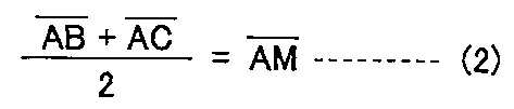
이에 의해, 식 (2)를, 기초원 반경 Rb, 이뿌리원 반경 Rf, 이끝원 반경 Ra, 회전 각도 α를 사용하여 나타내면, 하기의 식 (3)으로 나타낼 수 있다. 이에 의해, 식 (3)으로부터 하기의 식 (4)를 도출함으로써 회전 각도 α를 구할 수 있다.By this, if Formula (2) is shown using the base circle radius Rb, the root root radius Rf, the tooth tip radius Ra, and the rotation angle (alpha), it can be represented by following formula (3). Thereby, the rotation angle (alpha) can be calculated | required by deriving following formula (4) from Formula (3).

그리고 측정자(16a)의 Y축 방향으로의 이동량은, 측정 종료 위치(C)와 측정 종료 위치(C') 사이의 거리로 되므로, 하기하는 식 (5)에 의해, 그 최소로 되는 이동량을 구할 수 있다.Since the movement amount in the Y-axis direction of the

따라서, 본 발명에 관한 기어 측정 방법에 따르면, 작업물(W)의 기초원(Wb) 상의 접점 Ao로부터 양방향으로 회전 각도 α로 회전한 위치를 각각 접점 A, A'로 하고, 이 접점 A, A'에 접하는 접선 L, L'를 따라 작업물(W)의 회전에 따라서 측정자(16a)를 이동시키고, 이 접선 L, L'의 교점(M)을 측정 개시 위치(B, B')와 측정 종료 위치(C, C') 사이의 중점으로 함으로써, 측정자(16a)의 Y축 방향으로의 이동량인 측정 종료 위치(C, C') 사이의 거리를 짧게 할 수 있으므로, 측정자(16a)의 X-Y 평면 내에서의 이동 범위를 작게 할 수 있다. 이 결과, 대형의 작업물(W)의 치형 형상을 측정하는 경우라도, 공간을 절약하여 측정을 행할 수 있으므로, 기계의 소형화를 도모할 수 있다.Therefore, according to the gear measuring method according to the present invention, the positions rotated at a rotation angle α in both directions from the contact Ao on the base circle Wb of the workpiece W are respectively referred to as the contacts A and A ', and the contacts A, The
또한, 작업물(W)의 회전에 따라서 측정자(16a)를 접선 L, L'를 따라 이동시킴으로써, 측정 개시 위치(B, B')로부터 측정 종료 위치(C, C')에 걸쳐, 측정자(16a)와 작업물(W)의 우측 치면(WR) 및 좌측 치면(WL)의 접촉 각도를 항상 일정하게 할 수 있다. 이에 의해, 측정 오차의 발생을 억제할 수 있다. Further, by moving the
본 발명은 피측정 기어의 크기에 관계없이, 고정밀도로 그 치면 형상을 측정할 수 있는 기어 측정 방법에 적용 가능하다.This invention is applicable to the gear measuring method which can measure the tooth surface shape with high precision, regardless of the magnitude | size of a gear to be measured.
Claims (1)
피측정 기어의 기초원 상의 기준점으로부터 한쪽에 소정의 회전 각도로 회전 배치한 일측 접점에 접하는 일측 접선과, 피측정 기어의 기초원 상의 기준점으로부터 다른 쪽에 상기 소정의 회전 각도로 회전 배치한 타측 접점에 접하는 타측 접선을 설정하고,
상기 한쪽 치면의 측정시에, 상기 측정자를 상기 일측 접선을 따라 이동시키는 한편,
상기 다른 쪽 치면의 측정시에, 상기 측정자를 상기 타측 접선을 따라 이동시키고,
상기 일측 접선과 상기 타측 접선의 교점을, 상기 일측 접선상 및 상기 타측 접선상에 있어서의 측정 개시 위치와 측정 종료 위치 사이의 중점으로 하는 것을 특징으로 하는, 기어 측정 방법. The tooth shape of the gear under measurement is controlled by synchronously controlling the movement of the measurer and the rotation of the gear under measurement, and linearly moving the measuring member in contact with one tooth surface or the other tooth surface of the gear under measurement in accordance with the rotation of the gear under measurement. In the gear measuring method of measuring,
One side tangent contacting one side contact rotated and disposed at a predetermined rotational angle on one side from a reference point on the base circle of the gear to be measured, and the other side contact rotated at the predetermined rotational angle on the other side from the reference point on the base circle of the gear to be measured. Set the other side of the tangent line,
In the measurement of the one tooth surface, the measurer is moved along the one tangent line,
In the measurement of the other tooth surface, the measurer is moved along the other tangent line,
The intersection point of the said one side tangent line and the said other side tangent is made into the center point between the measurement start position and the measurement end position on the said one side tangent and the said other side tangent, The gear measuring method characterized by the above-mentioned.
Applications Claiming Priority (2)
| Application Number | Priority Date | Filing Date | Title |
|---|---|---|---|
| JPJP-P-2008-289434 | 2008-11-12 | ||
| JP2008289434A JP2010117196A (en) | 2008-11-12 | 2008-11-12 | Method of measuring gear |
Publications (1)
| Publication Number | Publication Date |
|---|---|
| KR20110079718A true KR20110079718A (en) | 2011-07-07 |
Family
ID=42169902
Family Applications (1)
| Application Number | Title | Priority Date | Filing Date |
|---|---|---|---|
| KR1020117010654A KR20110079718A (en) | 2008-11-12 | 2009-10-27 | Method of measuring gear |
Country Status (7)
| Country | Link |
|---|---|
| US (1) | US20110247436A1 (en) |
| EP (1) | EP2365277A1 (en) |
| JP (1) | JP2010117196A (en) |
| KR (1) | KR20110079718A (en) |
| CN (1) | CN102216725A (en) |
| TW (1) | TW201026415A (en) |
| WO (1) | WO2010055766A1 (en) |
Cited By (1)
| Publication number | Priority date | Publication date | Assignee | Title |
|---|---|---|---|---|
| KR20150142774A (en) * | 2014-06-11 | 2015-12-23 | 기어테크 주식회사 | Probe head system for gear testing apparatus |
Families Citing this family (24)
| Publication number | Priority date | Publication date | Assignee | Title |
|---|---|---|---|---|
| JPWO2010122680A1 (en) * | 2009-04-24 | 2012-10-25 | 株式会社東京テクニカル | Tooth profile measurement method for involute gears |
| JP5255012B2 (en) | 2010-04-02 | 2013-08-07 | 三菱重工業株式会社 | Calibration method of gear measuring device |
| DE102010023728A1 (en) * | 2010-06-14 | 2011-12-15 | Liebherr-Verzahntechnik Gmbh | Method of manufacturing a plurality of identical gears by means of machining |
| JP5854661B2 (en) * | 2011-06-28 | 2016-02-09 | 三菱重工業株式会社 | Calibration method of probe for shape measurement |
| EP2653826B1 (en) * | 2012-04-19 | 2020-02-19 | General Electric Technology GmbH | Measuring tool for a disc coil |
| DE202012011761U1 (en) * | 2012-11-27 | 2013-01-11 | Horst Knäbel | Device for checking a sprocket |
| WO2015166035A1 (en) * | 2014-05-02 | 2015-11-05 | Marposs Societa' Per Azioni | Apparatus and method for checking the position and/or dimensions of a workpiece |
| CN103994744B (en) * | 2014-06-06 | 2017-02-15 | 陕西法士特齿轮有限责任公司 | Tooth profile measuring method |
| JP6537915B2 (en) * | 2015-07-27 | 2019-07-03 | Ntn株式会社 | Pitch cone angle measuring method and measuring apparatus |
| JP6862636B2 (en) * | 2016-04-06 | 2021-04-21 | 株式会社ジェイテクト | Gear measuring method and measuring device |
| EP3255373B1 (en) * | 2016-06-09 | 2019-04-24 | Klingelnberg AG | Contact measurement on the tooth flank of a gear wheel |
| DE102017000072A1 (en) * | 2017-01-05 | 2018-07-05 | Liebherr-Verzahntechnik Gmbh | Method for automatically determining the geometric dimensions of a tool in a gear cutting machine |
| CN108562256B (en) * | 2017-11-29 | 2020-09-04 | 中国航发沈阳黎明航空发动机有限责任公司 | Tooth top height measuring method for incomplete circular arc end in middle of tooth profile |
| US20190301971A1 (en) * | 2018-04-02 | 2019-10-03 | Hota Industrial Mfg. Co., Ltd. Taiwan Science Park Branch | Automatic System for Processing and Testing Gears |
| CN109654983B (en) * | 2019-01-04 | 2020-12-25 | 中国航发南方工业有限公司 | Mouse-tooth disc pair coaxiality and indexing uniform distribution error detection device |
| CN109654984B (en) * | 2019-01-04 | 2021-01-01 | 中国航发南方工业有限公司 | Method for detecting coaxiality error of mouse tray to central axis |
| CN109764833B (en) * | 2019-01-04 | 2021-01-01 | 中国航发南方工业有限公司 | Detection method |
| CN109654985B (en) * | 2019-01-04 | 2021-01-01 | 中国航发南方工业有限公司 | Mouse tray detection device |
| CN109654978B (en) * | 2019-01-04 | 2021-02-09 | 中国航发南方工业有限公司 | Mouse tooth disc tooth surface shape depth error detection method |
| CN109654986A (en) * | 2019-01-04 | 2019-04-19 | 中国航发南方工业有限公司 | Mouse tooth disk is to end face parallelism error detection method |
| CN109654979B (en) * | 2019-01-04 | 2021-01-01 | 中国航发南方工业有限公司 | Mouse tooth disc tooth surface shape depth error detection device |
| DE102019104891B3 (en) * | 2019-02-26 | 2020-03-12 | Liebherr-Verzahntechnik Gmbh | Method for calibrating a probe in a gear cutting machine |
| DE102019104812A1 (en) * | 2019-02-26 | 2020-08-27 | KAPP NILES GmbH & Co. KG | Method for grinding or polishing a gear or a workpiece with a gear-like profile in a grinding or polishing machine |
| CN113029060B (en) * | 2021-04-30 | 2022-11-11 | 西安法士特汽车传动有限公司 | Tooth form positioning method and tooth form positioning control system |
Family Cites Families (5)
| Publication number | Priority date | Publication date | Assignee | Title |
|---|---|---|---|---|
| JPS5896208A (en) * | 1981-12-04 | 1983-06-08 | Mitsubishi Heavy Ind Ltd | Measuring method for tooth profile error |
| DE3717666A1 (en) * | 1987-05-26 | 1988-12-08 | Hoefler Willy | METHOD AND DEVICE FOR TESTING THE FLANK PROFILE OF THE TOOTHED FLANGES OF GEARS |
| JP2554157B2 (en) * | 1989-01-24 | 1996-11-13 | 三菱重工業株式会社 | Tooth profile error measurement method |
| JP2995258B2 (en) | 1991-10-24 | 1999-12-27 | 住友重機械工業株式会社 | Gear measuring method and gear grinding machine |
| JP3186963B2 (en) * | 1995-12-27 | 2001-07-11 | 大阪精密機械株式会社 | Gear tooth thickness measurement method |
-
2008
- 2008-11-12 JP JP2008289434A patent/JP2010117196A/en active Pending
-
2009
- 2009-10-27 WO PCT/JP2009/068362 patent/WO2010055766A1/en active Application Filing
- 2009-10-27 US US13/128,746 patent/US20110247436A1/en not_active Abandoned
- 2009-10-27 EP EP09826016A patent/EP2365277A1/en not_active Withdrawn
- 2009-10-27 KR KR1020117010654A patent/KR20110079718A/en not_active Application Discontinuation
- 2009-10-27 CN CN200980145290.6A patent/CN102216725A/en active Pending
- 2009-10-28 TW TW098136518A patent/TW201026415A/en unknown
Cited By (1)
| Publication number | Priority date | Publication date | Assignee | Title |
|---|---|---|---|---|
| KR20150142774A (en) * | 2014-06-11 | 2015-12-23 | 기어테크 주식회사 | Probe head system for gear testing apparatus |
Also Published As
| Publication number | Publication date |
|---|---|
| CN102216725A (en) | 2011-10-12 |
| US20110247436A1 (en) | 2011-10-13 |
| TW201026415A (en) | 2010-07-16 |
| EP2365277A1 (en) | 2011-09-14 |
| WO2010055766A1 (en) | 2010-05-20 |
| JP2010117196A (en) | 2010-05-27 |
Similar Documents
| Publication | Publication Date | Title |
|---|---|---|
| KR20110079718A (en) | Method of measuring gear | |
| CN109465502B (en) | Method and apparatus for shaving teeth | |
| KR100644118B1 (en) | Gear grinding machine | |
| KR101093473B1 (en) | Gearing apparatus, and gear working machine | |
| TWI474891B (en) | Calibration method of gear measuring device | |
| US9539659B2 (en) | Gear machining apparatus | |
| US20110179659A1 (en) | Method of measuring an involute gear tooth profile | |
| JP2016083729A (en) | Geometric error identification system, and geometric error identification method | |
| US9541914B2 (en) | Wire electric discharge machine and calculation method for wire support positions of wire electric discharge machine | |
| JP2016078177A (en) | Machine tool | |
| JP5479254B2 (en) | Gear grinding machine | |
| JP2013129000A (en) | Processing method and processsing device | |
| JP5854661B2 (en) | Calibration method of probe for shape measurement | |
| CN106735324B (en) | Globoid cam processing detection all-in-one machine and online test method | |
| JP3986320B2 (en) | Gear machining method and apparatus | |
| CN112475591A (en) | Double-swing-head five-axis linkage laser processing machine tool and working method | |
| CN107175359A (en) | X-shaped slide block guide rail processing method | |
| KR101271222B1 (en) | CNC lathe | |
| CN104646766A (en) | Milling method of large-module straight tooth bevel gear | |
| CN104827353B (en) | A kind of numerical control machining center of multiaxis multi-panel processing | |
| CN209085524U (en) | Blind hole depth is greater than 2 meters of hole inner diameter measuring device | |
| US11378379B2 (en) | Tool cutting edge measuring device and machine tool | |
| TWI492820B (en) | Rigid brittle plate chamfering device | |
| JP3898437B2 (en) | Grooving method and processing apparatus used directly for the implementation | |
| JP2006021277A (en) | Tool centering method and tool measuring method |
Legal Events
| Date | Code | Title | Description |
|---|---|---|---|
| A201 | Request for examination | ||
| E601 | Decision to refuse application |