KR20110033924A - Method and optical device for analyzing a mark on a translucent or transparent curved wall - Google Patents
Method and optical device for analyzing a mark on a translucent or transparent curved wall Download PDFInfo
- Publication number
- KR20110033924A KR20110033924A KR1020117001769A KR20117001769A KR20110033924A KR 20110033924 A KR20110033924 A KR 20110033924A KR 1020117001769 A KR1020117001769 A KR 1020117001769A KR 20117001769 A KR20117001769 A KR 20117001769A KR 20110033924 A KR20110033924 A KR 20110033924A
- Authority
- KR
- South Korea
- Prior art keywords
- mark
- light source
- curved wall
- camera
- virtual image
- Prior art date
Links
Images


Classifications
-
- G—PHYSICS
- G06—COMPUTING; CALCULATING OR COUNTING
- G06K—GRAPHICAL DATA READING; PRESENTATION OF DATA; RECORD CARRIERS; HANDLING RECORD CARRIERS
- G06K7/00—Methods or arrangements for sensing record carriers, e.g. for reading patterns
- G06K7/10—Methods or arrangements for sensing record carriers, e.g. for reading patterns by electromagnetic radiation, e.g. optical sensing; by corpuscular radiation
- G06K7/10544—Methods or arrangements for sensing record carriers, e.g. for reading patterns by electromagnetic radiation, e.g. optical sensing; by corpuscular radiation by scanning of the records by radiation in the optical part of the electromagnetic spectrum
- G06K7/10712—Fixed beam scanning
- G06K7/10722—Photodetector array or CCD scanning
- G06K7/10732—Light sources
-
- G—PHYSICS
- G06—COMPUTING; CALCULATING OR COUNTING
- G06V—IMAGE OR VIDEO RECOGNITION OR UNDERSTANDING
- G06V30/00—Character recognition; Recognising digital ink; Document-oriented image-based pattern recognition
- G06V30/10—Character recognition
- G06V30/22—Character recognition characterised by the type of writing
- G06V30/224—Character recognition characterised by the type of writing of printed characters having additional code marks or containing code marks
Abstract
본 발명은 투명성 재료나 반투명성 재료로 만들어진 만곡된 벽부(3)의 외측면(31) 상에 형성된 마크(2)를 분석하기 위하여, 발광면(S)을 갖는 광원(5)과 관찰 광 축선(A)을 나타내는 카메라(6)를 사용하는 방법에 관한 것으로서, 상기 방법은:
먼저 상기 광원(5)의 상기 발광면(S)의 허상(S')의 범위가 상기 마크(2)의 표면을 완전히 커버하고;
상기 광원(5)의 상기 발광면(S)의 허상(S')의 휘도가 일정한 방식으로;
상기 광원을 넓고 일정하게 하는 단계; 및
상기 마크(2)가 분석될 수 있도록 상기 허상(S')의 표면상에 중첩된 상기 마크(2)의 표면을 관찰하는 단계에 의해 특징지워진다.The present invention provides a light source 5 having an emitting surface S and observation light for analyzing the marks 2 formed on the outer surface 3 1 of the curved wall portion 3 made of a transparent material or a translucent material. A method of using a camera 6 representing an axis A, the method comprising:
First, the range of the virtual image S 'of the light emitting surface S of the light source 5 completely covers the surface of the mark 2;
The luminance of the virtual image S 'of the light emitting surface S of the light source 5 is constant;
Making the light source wide and constant; And
Characterized by observing the surface of the mark 2 superimposed on the surface of the virtual image S 'so that the mark 2 can be analyzed.
Description
본 발명은 반투명 재료나 투명 재료로 만들어진 만곡된 벽부의 외측면 상에 형성된 코드와 같은 마크를 일반적인 감지로 판독하는 기술 분야에 관한 것이다.The present invention relates to the technical field of reading marks, such as codes formed on the outer surface of curved walls made of translucent material or transparent material, by general sensing.
본 발명은 용기, 특히 유리나 플라스틱 재료로 만들어진 용기(예를 들면: 병, 단지, 벌브(bulb), 유리병, 안과 렌즈, 등)의 외측 벽부에 제공된 마크, 기호 또는 코드를 판독하는 분야에 특히 유리하지만, 이와 같은 분야로만 한정되는 것은 아니다.The invention particularly relates to the field of reading marks, symbols or codes provided on the outer wall of a container, in particular a container made of glass or plastic material (e.g. bottles, jars, bulbs, glass bottles, ophthalmic lenses, etc.). Advantageous, but not limited to this field.
물품의 만곡된 벽부 상의 마크나 코드를 판독하는 분야로서, 미국특허문헌 제2006/0091214호에는 산란 스크린을 조광하는 광원을 구비한 장치가 개시되어 있으며, 카메라의 렌즈를 위치시키기 위해 상기 산란 스크린의 중심에 구멍이 형성되어 있다. 카메라의 축선은 산란 스크린의 축선과 동일 선상에 있다. 산란 스크린은 광 공급용으로 제공된 산란 챔버가 끼워맞춰지며, 상기 산란 챔버는 코드 판독을 위해 다중 입사각을 제공한다.In the field of reading a mark or code on a curved wall of an article, US Patent Publication No. 2006/0091214 discloses a device having a light source for illuminating a scattering screen. A hole is formed in the center. The axis of the camera is collinear with the axis of the scattering screen. The scattering screen is fitted with a scattering chamber provided for light supply, which provides multiple angles of incidence for code reading.
산란 스크린의 표면은 그 중심에 발광-자유 구역이 있으며 상기 발광-자유 구역은 카메라 렌즈에 대응한다는 것을 알 수 있다. 예를 들면, 유리 표면처럼 정반사를 만들어낼 수 있는 물품으로써, 카메라는 검사될 표면에서 반사된 공급원의 발광을 관찰한다. 공급원의 발광-자유 구역은 코드 판독을 방해하는 이미지의 어두운 구역을 발생시킨다.It can be seen that the surface of the scattering screen has a light-free zone at its center and the light-free zone corresponds to the camera lens. For example, as an article capable of producing specular reflection, such as a glass surface, the camera observes the emission of the reflected source from the surface to be inspected. The light-free zone of the source generates a dark zone of the image that interferes with the code reading.
더욱이, 상기 특허문헌에 기재된 장치가 불투명 물체 상에 형성된 코드를 판독하려는 것을 알 수 있다. 도 1로부터 알 수 있는 바와 같이, 2개의 굴절면(Es 및 Ei)을 나타내는, 투명하거나 반투명한 물품 상의 판독 코드(2)는 특정 문제를 일으킨다. 이러한 실시예에 있어서, 코드(2)가 물품의 외측 반사면(Es) 상에 마크된다. 따라서, 물품의 내측면(Ei) 상의 반사에 의해 형성된 외측 반사면(Es)의 이미지(I)가 나타나게 된다. 물품의 내측면(Ei) 상의 반사에 의해 얻어진 이러한 간섭 이미지는 코드에 대해 오프셋되어, 상기 물품의 외측 반사면(Es) 상의 코드의 적당한 검출을 방해한다.Furthermore, it can be seen that the apparatus described in the above patent document attempts to read a code formed on an opaque object. As can be seen from FIG. 1, the
기술적 측면에 있어서, 용기가 성형되는 주형의 개수에 대응하는 상기 용기 상의 코드를 판독하도록 사용되는 장치가 미국특허문헌 제4,644,151호에 제공된다. 이러한 코드는 돋을 새겨진 일련의 부분, 즉 "비드(beads)"를 포함하며, 각각의 비드는 밀리미터 정도의 직경을 나타낸다. 코드가 광원에 의해 조광되고, 돋을 새겨진 부분에 의해 반사된 상기 광원의 광선은 용기 상에 형성된 코드를 판정하도록 선형 카메라에 의해 재생된다. 이러한 판독 장치는 검사될 표면에 대해 거의 돋을 새겨지지 않거나 전혀 새겨지지 않은 코드를 판독할 수 없다. 더욱이, 이러한 장치는 예를 들면 1 밀리미터보다 작은 매우 작은 패턴이나 특성을 갖는 코드를 판독하는데 적당하지 않다. 더욱이, 이러한 장치는 용기의 내측면 상에서 반사 결과로 나타난 이미지로부터의 간섭을 피할 수 없다. 결국, 이러한 장치는 용기의 큰 각도의 범위 상에서 만들어진 코드를 판독하기 위해 일정한 피치로 스캐닝될 필요가 있다.In a technical aspect, a device used to read a code on the container corresponding to the number of molds in which the container is molded is provided in US Pat. No. 4,644,151. These cords include a series of embossed portions, or "beads", each bead having a diameter of about a millimeter. The code is dimmed by the light source, and the light rays of the light source reflected by the raised portions are reproduced by the linear camera to determine the code formed on the container. Such a reading device cannot read codes that are hardly embossed or not engraved on the surface to be inspected. Moreover, such devices are not suitable for reading codes with very small patterns or properties, for example less than one millimeter. Moreover, such an apparatus cannot avoid interference from the image resulting from the reflection on the inner side of the container. As a result, such devices need to be scanned at a constant pitch in order to read codes made over a large range of angles of the container.
따라서, 본 발명은, 투명하거나 불투명한 반사 재료로 만들어진 만곡된 벽부의 외측면 상에서 실행되고 작은 패턴이나 특성을 갖는 마크를 신뢰할만한 방식으로 분석하는데 사용되는 새로운 광학 기술을 제공함으로써, 종래 기술의 단점을 해소하는 것이다.Accordingly, the present invention provides a novel optical technique which is carried out on the outer surface of a curved wall made of transparent or opaque reflective material and used to reliably analyze a mark having a small pattern or characteristic, thereby providing a disadvantage of the prior art. To solve the problem.
이러한 목적을 달성하기 위하여, 본 발명은 투명성 재료나 반투명성 재료로 만들어진 만곡된 벽부의 외측면 상에 만들어진 마크를 분석하기 위하여, 발광면을 구비한 광원과 관찰 광 축선을 나타내는 카메라를 사용하는 방법을 제시한다.In order to achieve this object, the present invention provides a method of using a camera having a light source with an emitting surface and a viewing optical axis to analyze a mark made on an outer surface of a curved wall made of a transparent material or a translucent material. To present.
본 발명에 따르면, 본 발명의 방법은:According to the invention, the method of the invention is:
먼저 상기 광원의 상기 발광면의 허상의 범위가 상기 마크의 표면을 완전히 커버하고,First, the range of the virtual image of the light emitting surface of the light source completely covers the surface of the mark,
상기 광원의 상기 발광면의 상기 허상의 휘도가 일정한 방식으로, 상기 광원을 넓고 일정하게 하는 단계; 및Making the light source wide and constant in such a manner that the luminance of the virtual image of the light emitting surface of the light source is constant; And
상기 마크가 분석될 수 있도록 허상(S')의 표면에 중첩된 상기 마크의 표면을 관찰하는 단계로 행해진다.And observing the surface of the mark superimposed on the surface of the virtual image S 'so that the mark can be analyzed.
일 실시예에 있어서, 본 발명의 방법은 카메라와 벽부 사이의 상대 이동 동안에 취해진 이미지나 일련의 이미지를 얻음으로써 마크 표면을 관찰하는 단계를 포함한다.In one embodiment, the method includes observing the mark surface by obtaining an image or a series of images taken during relative movement between the camera and the wall.
유리하게도, 본 발명의 방법은 만곡된 벽부의 곡률에 대한 광원의 발광면의 허상의 범위를 적용하는 단계를 포함한다.Advantageously, the method includes applying a range of the virtual image of the light emitting surface of the light source to the curvature of the curved wall portion.
또한 본 발명은 반투명하거나 투명한 재료로 만들어진 만곡된 벽부의 외측면 상에 만들어진 마크를 분석하는 장치를 제공하며, 상기 마크를 분석하는 장치는:The present invention also provides an apparatus for analyzing marks made on the outer surface of a curved wall made of translucent or transparent material, the apparatus for analyzing the marks:
발광면을 구비한 광원; 및A light source having a light emitting surface; And
상기 만곡된 벽부의 외측면에 실질적으로 수직한 관찰 광 축선을 구비한 렌즈가 제공된 카메라를 포함한다.And a camera provided with a lens having an observation light axis substantially perpendicular to the outer surface of the curved wall portion.
본 발명에 따라,According to the invention,
상기 광원의 상기 발광면의 허상의 범위가 상기 마크의 표면을 완전히 커버하고; The range of the virtual image of the light emitting surface of the light source completely covers the surface of the mark;
상기 광원의 상기 발광면의 상기 허상의 휘도가 일정하도록,So that the luminance of the virtual image of the light emitting surface of the light source is constant,
광원은 일정하고 넓은 발광부를 구비하고,The light source has a constant and wide light emitting portion,
카메라는 상기 허상의 표면상에 중첩된 상기 마크의 표면의 이미지를 획득하는데 사용된다.The camera is used to obtain an image of the surface of the mark superimposed on the surface of the virtual image.
일 실시예에 있어서, 광원은 카메라의 렌즈에 대해 오프셋된 백라이트 산란 스크린을 포함한다.In one embodiment, the light source comprises a backlight scattering screen offset relative to the lens of the camera.
일 실시예에 있어서, 편향기 광소자는 카메라의 렌즈의 전방에 배치된다.In one embodiment, the deflector optical element is disposed in front of the lens of the camera.
일 실시예에 있어서, 산란 스크린은 서로 마주하여 배치된 미러에 의해 어느 한 쪽으로 연장된다.In one embodiment, the scattering screens are extended to either side by mirrors disposed opposite each other.
다른 한 실시예에 있어서, 산란 스크린은 미러와 산란 스크린이 연장되는 평면에 실질적으로 수직한 평면에서 연장하는 미러에 의해 연장된다.In another embodiment, the scattering screen is extended by a mirror extending in a plane substantially perpendicular to the plane in which the mirror and the scattering screen extend.
다른 일 실시예에 있어서, 상기 마크 분석 장치는 광소자를 산란 스크린과 만곡된 벽부 사이에서 포함하고, 상기 광소자는 광 공급원의 표면의 평면의 이미지를 카메라 렌즈의 동공(pupil)의 평면에 형성하도록 사용된다.In another embodiment, the mark analysis device comprises an optical element between the scattering screen and the curved wall portion, the optical element being used to form an image of the plane of the surface of the light source in the plane of the pupil of the camera lens. do.
다른 일 실시예에 있어서, 상기 마크 분석 장치는 카메라 렌즈와 만곡된 벽부 사이에 개재된 반투명 광소자를 포함하고, 산란 스크린은 상기 반투명 광소자의 평면과 관련하여 카메라 렌즈의 입구 동공에 대해 대칭적으로 배치된다.In another embodiment, the mark analysis device comprises a translucent optical element interposed between the camera lens and the curved wall, and the scattering screen is symmetrically disposed with respect to the entrance pupil of the camera lens with respect to the plane of the translucent optical element. do.
유리하게도, 마크는 레이저에 의해 얻어진 마킹이다.Advantageously, the mark is a marking obtained by a laser.
첨부한 도면을 참조하여 설명된 실시예로부터 여러 다양한 특징을 알 수 있을 것이고, 이러한 실시예는 본 발명을 한정하려는 것이 아닌 단지 예시를 위한 것임을 알 수 있을 것이다.From the embodiments described with reference to the accompanying drawings will be seen a variety of features, it will be appreciated that such embodiments are for illustrative purposes only and not intended to limit the present invention.
도 1은 본 발명에 의해 해결될 수 있는 간섭 이미지의 문제점을 설명하는 다이어그램이다.
도 2는 본 발명에 따른 분석 장치가 작동하는 원리를 나타낸 도면이다.
도 3은 도 2의 선 Ⅲ-Ⅲ에 따라 취한 실질적인 평면도이다.
도 4 및 도 5는 각각 프리즘 작동식 분석 장치의 일 실시예의 평면도 및 정면도이다.
도 6 및 도 7은 각각 프레넬 렌즈를 실행하는 분석 장치의 다른 일 실시예의 평면도와 정면도이다.
도 8은 빔 분할기를 실행하는 분석 장치의 다른 일 실시예에 대한 정면도이다.1 is a diagram illustrating a problem of an interference image that can be solved by the present invention.
2 is a view showing the principle of operation of the analysis device according to the present invention.
3 is a substantially plan view taken along line III-III of FIG.
4 and 5 are plan and front views, respectively, of one embodiment of a prism operated analysis device.
6 and 7 are plan and front views, respectively, of another embodiment of an analysis device implementing a Fresnel lens.
8 is a front view of another embodiment of an analysis device implementing a beam splitter.
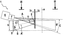
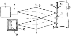
도 2 및 도 3으로부터 알 수 있는 바와 같이, 본 발명은 2개의 굴절면(31, 32)을 갖는 물품(예를 들면, 안과 렌즈 또는 중공의 물품(용기, 벌브(bulb), 관, 등))의 만곡된 벽부(3)의 외측면(31) 상의 광학 기호나, 마크나, 또는 임의의 종류의 보다 일반적인 마킹(2)을 분석하는데 사용되는 분석 장치를 제공한다. 마크(2)는 (잉크, 레이저 마킹 등을 형성함으로써) 임의의 적당한 방식으로 신중하게 만들어지고, 예를 들면 바 코드, 문자숫자식 코드, 또는 데이터 매트릭스와 같은 다양한 1차원 형태나 2차원 형태를 나타낼 수 있다.As can be seen from FIGS. 2 and 3, the present invention relates to articles having two refractive surfaces 3 1 , 3 2 (eg, ophthalmic lenses or hollow articles (vessels, bulbs, tubes, etc.). An analysis apparatus is used for analyzing optical symbols, marks, or any more general marking (2) on the outer surface (3 1 ) of the curved wall (3).
벽부(3)는 반사식이고 투명성이나 반투명성인 재료로 만들어진다. 예를 들면, 벽부(3)는 유리나 플라스틱으로 만들어진다. 벽부(3)는 물품의 외측면(31)과 내측면(32)에 대응하는 2개의 굴절면을 갖는다. 외측면(31)은 상기 외측면(31)과 상호작동하는 내측면(32)과 실질적으로 평행하게 뻗어있어서 물품의 벽부의 두께를 형성한다. 외측면(31)은 미러와 같이 사용되므로 반사면이다.The wall part 3 is made of a material which is reflective and transparent or translucent. For example, the wall portion 3 is made of glass or plastic. The wall portion 3 has two refracting surfaces corresponding to the outer side 3 1 and the inner side 3 2 of the article. The outer side 3 1 extends substantially parallel to the inner side 3 2 cooperating with the outer side 3 1 to form the thickness of the wall portion of the article. The outer surface 3 1 is used as a mirror and thus is a reflective surface.
본 발명의 분석 장치(1)는 비-평면 벽부(3), 즉 만곡된 임의의 형상의 벽부 상에 만들어진 마크(2)를 분석할 수 있다는 것을 알 수 있다. 도 2 및 도 3에 도시된 실시예에 있어서, 벽부(3)의 형상은 반-원통형이다. 외측면과 내측면(31 및 32)에 수직한 횡단면에 있어서, 상기 외측면(31)은 도시된 실시예처럼 길이방향 축선(x)에 중심이 있는 원의 한 부분으로 결정된 곡률부이다. 벽부(3)가 실린더의 일부이기 때문에, 길이방향 축선(x)은 일직선이지만, 그러나 카메라(6)의 횡단면에 수직한 평면에서 곡률을 갖는 벽부(3)를 파악할 수 있다.It can be seen that the
분석 장치(1)는 광원(5)과 렌즈(7)가 통상적으로 제공된 카메라(6)를 포함하며, 상기 렌즈(7)는 관찰 광 축선(A)과 광학 시계(C)를 구비한다. 본래, 카메라(6)의 광학 시계(C)는 만곡된 벽부의 외측면(31) 상에 만들어진 마크(2)의 적어도 전체 영역을 커버하거나 관찰하는데 사용되며, 상기 카메라(6)는 통상적으로 매트릭스 카메라이다.The
광원(5)은 외측면(31)을 발광하기 위한 일정하고 넓은 발광면(S)을 포함하며, 상기 외측면은 주어진 그 스펙트럼 특성에 따라 반사에 의해 상기 발광면(S)의 허상(S')을 만든다. 따라서, 허상(S')은 외측면(31)에서의 반사 이후에 카메라에 의해 보여지는 바와 같이 광원(5)의 표면에 대응한다.The
도 3에 있어서, 명확하게 하기 위하여, 이미지(S')가 도 2에서와 같이 동일한 위치에 있는 것으로 도시되었다. 이와 같이 도시된 구성에 있어서, 외측면(31)으로 이루어진 볼록 미러의 비점수차가 무시된다. 실제로, 외측면(31)이 축선(x)으로부터 반경(R)을 갖는 원통형 미러일 수 있는 미러라면, 도 3의 단면에 포함된 발광면(S)의 수평방향 세그먼트의 허상이 거의 R/2의 거리, 즉 외측면(31)에 보다 근접한 거리에 위치된 수평방향의 세그먼트(S')일 수 있는 한편, 상기 외측면(31)의 동일면 상에 형성된 허상으로 이루어질 수 있다. 이와 같이 비점수차 때문에, 완전한 분석을 위하여 도 2의 허상(S)의 위치(S')가 도 2의 단면에 놓인 발광면(S)의 수직방향 세그먼트의 이미지에 대응하는 것을 알 수 있다.In FIG. 3, for the sake of clarity, the image S ′ is shown as being in the same position as in FIG. 2. In the configuration shown in this way, the astigmatism of the convex mirror made of the outer surface 3 1 is ignored. Indeed, if the outer surface 3 1 is a mirror which can be a cylindrical mirror having a radius R from the axis x , the virtual image of the horizontal segment of the emitting surface S contained in the cross section of FIG. 3 is almost R /. 2 distance, i.e., it may consist of a virtual image formed on the same side of the outer surface (31) segment of the horizontal position to a closer distance (S ') one the other hand, the outside face of the can (31). Because of this astigmatism, it can be seen that the position S ′ of the virtual image S of FIG. 2 corresponds to the image of the vertical segment of the light emitting surface S lying in the cross section of FIG. 2 for complete analysis.
본 발명에 따르면, 광원(5)은 일정하고 넓은 발광면을 구비한다. According to the invention, the
허상(S')의 범위는 마크(2)의 표면적을 완전하게 커버하고; The range of the virtual image S 'completely covers the surface area of the
허상(S')의 휘도가 일정하도록, 광원(5)이 형성된다.The
공급원의 허상(S')의 휘도가 일정한데, 이는 즉, 음영 구역을 포함하지 않는다는 것이다.The luminance of the virtual image S 'of the source is constant, i.e. it does not include the shadow area.
더욱이, 허상(S')은 마크(2)의 총 표면적을 커버한다. 따라서, 허상(S')의 면적은 마크(2)의 면적보다 작지 않다. 실제로, 그리고 바람직하게, 분석 장치(1)와 물품 사이의 상대 이동에 무관하게, 마크(2)의 표면이 허상(S')의 표면에 의해 완전하게 커버되는 것이 확실하도록, 허상(S')의 면적은 마크(2)의 영역보다 더 크다. 바람직하게, 허상(S')의 면적은 마크(2)의 면적보다 적어도 1.5배 더 크다.Moreover, the virtual image S 'covers the total surface area of the
카메라(6)가 마크(2)에 대한 백그라운드로서 광원(5)의 표면(S)의 허상(S')을 관찰한다는 것을 알 수 있다. 이러한 마크(2)와 허상(S')이 시계(C)에 포함된 상태에서 마크(2)는 상기 허상(S') 내에 포함된다.It can be seen that the
허상(S')의 명암도가 발광의 간섭에 의해 중단되지 않는 백그라운드를 충분히 이루도록 광원(5)이 관찰될 수 있다. 광원(5)은 펄스식 공급원이거나 연속식 공급원일 수 있다.The
광원(5)의 표면(S)의 치수는 상기 기재로부터 직접적으로 알 수 있다. 카메라(6)는 광학 시계(C)에서 반사된 광원의 허상(S')의 표면을 관찰한다. 광학 시계(C)의 확장부(C')는 광원(5)의 표면(S)의 치수(높이(h) 및 폭(l))를 결정하는데 사용된다. 도시된 실시예에 있어서, 표면(S)의 폭(l)은 횡단면에 놓여있는, 즉 외측면과 내측면(31 및 32)에 수직인 한편, 높이(h)는 길이방향 축선(x)을 따라 취해진다.The dimensions of the surface S of the
유리하게도, 광원(5)의 표면(S)은 외측면(31) 반사 이후에 관찰 축선(A)의 이미지(A')에 중심이 잡혀진다.Advantageously, the surface S of the
본 발명의 유리한 특징에 따르면, 관찰 방향, 즉 카메라의 관찰 광 축선(A)은 벽의 외측면(31)에 실질적으로 수직한다. 따라서 외측면(31) 반사 이후에 관찰 축선(A)의 이미지(A')는 또한 외측면(31)에 실질적으로 수직하기 때문에 관찰 입사각(a)은 작다. 관찰 광 축선(A)과 상기 관찰 광 축선(A)의 이미지(A')는 반사 이후에 실질적으로 평행하다. 본 발명에 있어서, 광 축선(A)과 이미지(A') 사이의 각도가 10°(a ≤5°)이거나 이보다 작고 전형적으로 바람직하게 6°(a ≤3°)인 경우에, 관찰 광 축선(A)은 실질적으로 상기 관찰 광 축선의 이미지(A')와 평행하다. 관찰 방향이 외측면(31)에 수직하는 한, 내측면(32) 상의 반사에 의해 형성된 상기 외측면의 제 2 이미지가 외측면(31)의 메인 이미지와 일치하여, 이중 마크(2)에 해당되는 간섭 이미지가 나타나지 않는다.According to an advantageous feature of the invention, the viewing direction, ie the viewing light axis A of the camera, is substantially perpendicular to the outer surface 3 1 of the wall. The observed angle of incidence a is therefore small since the image A 'of the viewing axis A after the lateral face 3 1 reflection is also substantially perpendicular to the lateral face 3 1 . The observation light axis A and the image A 'of the observation light axis A are substantially parallel after reflection. In the present invention, when the angle between the optical axis A and the image A 'is 10 ° (a ≤ 5 °) or less and typically 6 ° (a ≤ 3 °), the observation light axis (A) is substantially parallel to the image A 'of the observation light axis. As long as the viewing direction is perpendicular to the outer surface 3 1 , the second image of the outer surface formed by the reflection on the inner surface 3 2 coincides with the main image of the outer surface 3 1 , so that the double mark 2 ) Does not appear in the interference image.
본 발명으로부터 알 수 있는 바와 같이, 카메라(6)는 공급원의 허상(S')에 중첩된 마크(2)의 표면 이미지를 얻도록 사용된다. 즉, 카메라(6)는 허상(S')에 중첩된 마크(2)를 관찰하도록 사용된다. 마크(2)와 허상(S')은 관찰 축선(A)에 실질적으로 정렬된 상태이다.As can be seen from the present invention, the
카메라(6)로 얻어진 이미지는 마크(2)를 분석하거나 판독하도록 적용된 프로세서 유닛에 의해 처리된다. 상기 기재한 바와 같이 발광 조건과 관찰 조건이 주어져, 취해진 이미지에 간섭 이미지가 없으며, 상기 이미지에서 이미지 마크(2)는 마크가 용이하게 판독될 수 있게 하는 양호하고 일정한 콘트라스트로 나타난다.The image obtained with the
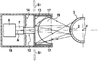
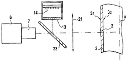
도 4 및 도 5에는 본 발명에 따른 장치의 제 1 실시예가 도시되어 있고, 상기 제 1 실시예에서 프리즘과 같은 광소자(11)가 관찰 광 축선(A)을 편향시키기 위해 카메라 렌즈(7)의 전방에 배치되어 분석 장치(1)가 보다 컴팩트하게 된다. 예를 들면, 렌즈(7)는 상기 렌즈의 단부에 장착된 프리즘(11)을 구비한 튜브(12)에 의해 펼쳐진다.4 and 5 show a first embodiment of the device according to the invention, in which in the first embodiment an
이러한 실시예에 있어서, 광원(5)은 예를 들면 일련의 발광 다이오드(LEDs)로 행해지는, 발광기(14)에 의한 백라이트인 산란 스크린(13)을 구비한다. 발광면(S)을 형성하는 산란 스크린(13)은 카메라 렌즈(7)에 대해 오프셋되어 있다. 즉, 산란 스크린(13)은 카메라(6)로부터 이격되어 있다. 이러한 도시된 실시예에 있어서, 산란 스크린(13)은 프리즘(11) 아래에 위치하며, 즉 상기 산란 스크린(13)은 물품의 길이방향 축선(x)을 따라서 렌즈(7)에 대해 오프셋되어 있다. 본래, 산란 스크린(13)이 프리즘(11) 상에 위치하도록, 조립체를 180° 피벗시킴으로써, 산란 스크린과 프리즘이 상이하게 위치하는 것을 파악할 수 있다.In this embodiment, the
유리하게도, 카메라(6)와, 상기 튜브(12)에 의해 펼쳐진 상기 카메라의 렌즈(7)가 개방 박스(16)에 장착되어 프리즘(11)에 의해 편향되기 전에 관찰 광 축선이 물품의 길이방향 축선(x)에 수직한다. 산란 스크린(13)이 프리즘(11) 아래에 위치된 상태에서, 표면(S)에 대한 법선이 물품의 길이방향 축선(x)에 수직한다. LED(14)는 상기 산란 스크린(13) 뒤에 장착된다.Advantageously, the observation light axis is in the longitudinal direction of the article before the
산란 스크린(13)은 미러(17)에 의해 어느 한 쪽으로 연장되며, 상기 미러(17)는 특정 방향, 특히 도시된 실시예에서는 만곡된 외측면(31)에 접한 평면에 배치된 수평 방향으로 광원(5)의 영역을 인위적으로 증가시키도록 위치된다. 따라서 광원(5)의 표면(S)은 미러(17)에서 반사된, 표면(S)의 허상에 대응하는 표면(S1)에 의해 어느 한쪽으로 증가된다. 일례로서, 미러(17)가 서로 마주하고 길이방향 축선(x)에 평행하여, 산란 스크린(13)을 연장시킬 수 있다. 미러(17)가 존재하기 때문에 산란 스크린(13)의 영역을 인위적으로 길이방향 축선(x)에 수직한 수평 방향으로 증가시킬 수 있다. 따라서, 박스(16)의 주어진 폭에 대하여, 광원(5)의 영역은 미러(17)의 2개의 표면적(S1)에 광원(5)의 표면적(S)을 더한 면적에 대응하기 때문에, 수평방향으로 연장된다(폭(l)). 미러가 존재하기 때문에, 광원(5)의 크기를 폭 방향으로 증가시키지 않으면서, 물품의 주변이나 주위를 따르는 관찰을 증가시킬 수 있다.The
따라서, 본 발명에 의해 광원(5)의 발광면(S)의 허상(S')의 범위는 만곡된 벽부(3)의 곡률에 적용될 수 있다. 따라서, 벽부(3)의 곡률이 크면 클수록(상기 벽부의 곡률 반경이 작으면 작을수록) 광원(5)의 표면의 폭(l)도 더 크게 된다.Therefore, according to the present invention, the range of the virtual image S 'of the light emitting surface S of the
다른 일 실시예에 있어서, 광원(5)의 표면적이 제 2 방향, 즉 수직 축선(x)을 따라서 인위적으로 증가할 수 있다는 것을 알 수 있다. 이러한 실시예에 있어서, 산란 스크린(13)은 미러(19)에 의해 연장되며, 상기 미러(19)는 미러(17)가 연장되는 평면과, 산란 스크린(13)이 연장되는 평면에 실질적으로 수직한 평면에 놓여 있다. 따라서, 광원(5)의 표면적은 미러(19) 상에서의 반사로부터 초래된 표면(S)의 허상에 대응하는 영역(S2) 만큼 수직면에서 증가된다.In another embodiment, it can be seen that the surface area of the
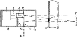
도 6 및 도 7에는 다른 일 실시예가 도시되어 있고, 이 다른 일 실시예에 있어서 분석 장치(1)는 광소자(21)를 산란 스크린(13)과 만곡된 벽부(3) 사이에서 포함하고, 상기 광소자(21)는 광원(5)의 표면(S)의 평면의 이미지를 카메라(6)의 렌즈(7)의 동공(pupil)의 평면에서 형성하도록 사용된다. 따라서, 프레넬 렌즈(Fresnel lens)와 같은 광소자(21)는 광원(5)의 평면을 물품의 길이방향 축선(x)과 결합하는데 사용된다. 광선은 벽부의 외측면(31)에서 반사된 이후에 렌즈에 의해 렌즈(7)의 동공에서 결합된다. 따라서, 이미지에 있어서, 광원(5)의 표면(S)은 만곡된 외측면(31)에 수직한 평면에 포함된 수평 방향으로 일정하고 넓게 나타난다.6 and 7 show another embodiment, in which the
이러한 실시예에 있어서, 관찰 및 발광 축선이, 프레넬 렌즈(21)를 통과하기 전에, 상호 평행하도록, 렌즈(7)를 포함한 카메라(6)가 LED(14)에 의해 백라이트인 산란 스크린(13) 상에 배치된다. 관찰 및 발광 축선이 프레넬 렌즈(21)의 사용 결과로서 10° 이하의 각도를 형성하여, 캐스팅 섀도우(casting shadows)를 피할 수 있음을 알 수 있다.In this embodiment, the
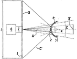
도 8에는 다른 일 실시예가 도시되어 있고, 이 다른 일 실시예에 있어서 관찰 및 발광 축선은 공통 직선이다. 이러한 실시예에 있어서, 광원을 산란시키는 스크린(13)의 표면은 벽부의 외측면(31)에서 반사된 이후에 카메라에 의해 관찰된다. 벽부 상에서 반사된 이후에, 산란 스크린(13)의 상기 표면이 수평 방향으로 넓게 나타나는 것을 보장하기 위하여, 프레넬 렌즈(21)가 예를 들면 렌즈(7)와 벽부 사이에 배치되어, 광원의 평면이 물품의 길이방향 축선과 일치하게 된다. 광선이 벽부의 외측면에서 반사된 이후에, 렌즈(7)의 동공에서 프레넬 렌즈(21)에 의해 결합된다. 따라서, 산란 스크린(13)의 표면이 만곡된 외측면(31)에 접한 평면에 포함된 수평 방향으로 일정하고 넓은 이미지에서 나타난다.8 shows another embodiment, in which the observation and emission axis is a common straight line. In this embodiment, the surface of the
관찰 광 축선(A)이 물품의 길이방향 축선(x)에 수직한다는 것을 알 수 있다. 공통 직선인 관찰 및 발광 축선의 경우에, 반투명 광소자(23)가 카메라(6)의 렌즈(7)와 만곡된 벽부의 외측면(31) 사이에 개재된다. 이러한 실시예에 있어서, 백라이트 산란 스크린(13)은 반투명 광소자(23)의 평면과 관련하여 카메라(6)의 렌즈(7)의 입구 동공과 대칭적으로 위치된다.It can be seen that the viewing light axis A is perpendicular to the longitudinal axis x of the article. In the case of the observation and light emission axis which are common straight lines, the translucent
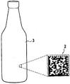
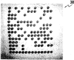
상기 기재로부터, 본 발명에 따른 분석 장치(1)가 양호한 조건하에서 마크(2)를 반사 및 투명 벽 상에서 얻도록 사용된다는 것을 알 수 있다. 본 발명의 분석 장치(1)는 도 9로부터 알 수 있는 바와 같이, 유리 용기의 벽부(3)에 형성된 매트릭스 코드와 같은 2차원 마크(2)를 판독하여 사용하는데 특히 유리하다는 것을 알 수 있다. 바람직하게, 매트릭스 코드는 레이저 엣칭에 의해 고온인, 용기 상에 만들어진 데이터 매트릭스 코드이다. 도 10으로부터 알 수 있는 바와 같이, 본 발명의 분석 장치(1)는 광원의 허상에 중첩된 코드(2)의 표면의 이미지(30)를 얻도록 사용된다. 이미지(30)의 백그라운드는 벽부에 의해 반사된 광원의 이미지로 이루어지기 때문에 희미하다. 코드(2)의 다양한 지점은 광을 편향시키고 이에 따라 이미지(30)에서 어두운 부분을 나타낸다. 광원은 완전한 코드를 포함한 환형 섹터를 조광하고, 상기 기재한 바와 같이 2개의 방향, 즉 물품의 수직 축선에 평행하고 수직한 방향으로 일정한 정도를 나타낸다. 도 10으로부터 명확하게 알 수 있는 바와 같이, 상기와 같은 방식으로 얻어진 바와 같은 이미지는 만족스러운 분해능을 나타내었다.It can be seen from the above description that the
더욱이, 이러한 분석 장치(1)가 컴팩트하므로, 휴대용 판독 장치의 형태로 행해질 수 있거나, 물품의 직선형 검사 장치에 용이하게 통합될 수 있다. 카메라와 벽부 사이의 상대 이동, 예를 들면 회전 이동 동안에 단일의 이미지 또는 일련의 연속된 이미지를 얻음으로써 마크(2)를 관찰할 수 있다. 상대 이동에 의해, 겹쳐질 수 있는 이미지가 함께 분석되어 마크(2)를 판독한다.Moreover, since such an
본 발명은 상기 기재한 실시예로 한정되는 것은 아니며, 본 발명에 대한 여러 변경 및 수정이 본 발명의 범주 내에서 가능하다는 것을 알 수 있을 것이다.It is to be understood that the present invention is not limited to the above described embodiments, and that various changes and modifications to the present invention are possible within the scope of the present invention.
Claims (11)
먼저 상기 광원(5)의 상기 발광면(S)의 허상(S')의 범위가 상기 마크(2)의 표면을 완전히 커버하고;
상기 광원(5)의 상기 발광면(S)의 상기 허상(S')의 휘도가 일정한 방식으로,
상기 광원을 넓고 일정하게 단계; 및
상기 마크(2)가 분석될 수 있도록 상기 허상(S')의 표면상에 중첩된 상기 마크(2)의 표면을 관찰하는 단계를 포함하는 것을 특징으로 하는 발광면을 갖는 광원과 관찰 광 축선을 나타내는 카메라를 사용하는 방법.In order to analyze the mark 2 formed on the outer surface 3 1 of the curved wall portion 3 made of transparent material or translucent material, the light source 5 having the light emitting surface S and the observation light axis A As a method of using the camera 6 indicating),
First, the range of the virtual image S 'of the light emitting surface S of the light source 5 completely covers the surface of the mark 2;
In such a manner that the luminance of the virtual image S 'of the light emitting surface S of the light source 5 is constant,
Making the light source wide and constant; And
And observing the surface of the mark 2 superimposed on the surface of the virtual image S 'so that the mark 2 can be analyzed. How to use the camera indicating.
상기 카메라와 상기 벽부 사이에서 상대 이동하는 동안에 찍힌 이미지나 일련의 이미지를 얻도록 상기 마크(2)의 표면을 관찰하는 단계를 포함하는 것을 특징으로 하는 발광면을 갖는 광원과 관찰 광 축선을 나타내는 카메라를 사용하는 방법.The method according to claim 1,
Observing the surface of the mark 2 so as to obtain an image or a series of images taken during relative movement between the camera and the wall; How to use it.
상기 만곡된 벽부(3)의 곡률에 대한 상기 광원(5)의 상기 발광면(S)의 상기 허상(S')의 범위를 적용시키는 단계를 포함하는 것을 특징으로 하는 발광면을 갖는 광원과 관찰 광 축선을 나타내는 카메라를 사용하는 방법.The method according to claim 1,
And applying a range of the virtual image S 'of the light emitting surface S of the light source 5 to the curvature of the curved wall portion 3. How to use a camera that represents the optical axis.
만곡된 벽부의 외측면(31)에 실질적으로 수직한 관찰 광 축선(A)을 갖는 렌즈(7)가 제공된 카메라(6)를 포함하고,
투명 재료나 반투명 재료로 만들어진 상기 만곡된 벽부(3)의 상기 외측면(31)에 형성된 마크(2)를 분석하는 장치에 있어서,
상기 광원의 상기 발광면(S)의 허상(S')의 범위가 상기 마크(2)의 표면을 완전히 커버하고;
상기 광원(5)의 상기 발광면(S)의 상기 허상(S')의 휘도가 일정하며;
상기 카메라(6)가 상기 허상(S')의 표면에 중첩된 상기 마크(2)의 표면의 이미지를 얻도록 사용되기 위하여,
상기 광원(5)은 일정하고 넓은 상기 발광부(S)를 갖는 것을 특징으로 하는 투명 재료나 반투명 재료로 만들어진 만곡된 벽부의 외측면에 형성된 마크를 분석하는 장치.A light source 5 having a light emitting surface S; And
A camera 6 provided with a lens 7 having an observation light axis A substantially perpendicular to the outer side surface 3 1 of the curved wall,
In the apparatus for analyzing the mark (2) formed on the outer surface (3 1 ) of the curved wall (3) made of transparent material or translucent material,
The range of the virtual image S 'of the light emitting surface S of the light source completely covers the surface of the mark 2;
The luminance of the virtual image S 'of the light emitting surface S of the light source 5 is constant;
In order for the camera 6 to be used to obtain an image of the surface of the mark 2 superimposed on the surface of the virtual image S ',
The light source (5) has a constant and wide said light emitting portion (S), characterized in that for analyzing the mark formed on the outer surface of the curved wall portion made of a transparent material or a translucent material.
상기 광원(5)은 상기 카메라(6)의 상기 렌즈(7)에 대해 오프셋된 백라이트 산란 스크린(13)을 포함하는 것을 특징으로 하는 투명 재료나 반투명 재료로 만들어진 만곡된 벽부의 외측면에 형성된 마크를 분석하는 장치.The method according to claim 4,
Mark formed on the outer surface of the curved wall part made of transparent material or translucent material, characterized in that the light source 5 comprises a backlight scattering screen 13 offset with respect to the lens 7 of the camera 6. Device to analyze.
편향기 광소자(11)는 상기 카메라(6)의 상기 렌즈(7)의 전방에 배치되는 것을 특징으로 하는 투명 재료나 반투명 재료로 만들어진 만곡된 벽부의 외측면에 형성된 마크를 분석하는 장치.The method according to claim 5,
A deflector optical element (11) is arranged for the front of the lens (7) of the camera (6), the device for analyzing the mark formed on the outer surface of the curved wall portion made of transparent material or translucent material.
상기 산란 스크린(13)은 서로 마주하여 배치된 미러(17)에 의해 어느 한쪽으로 연장가능한 것을 특징으로 하는 투명 재료나 반투명 재료로 만들어진 만곡된 벽부의 외측면에 형성된 마크를 분석하는 장치.The method according to claim 4 or 5,
Said scattering screen (13) is extendable to either side by mirrors (17) arranged opposite to each other, wherein the marks formed on the outer surface of the curved wall portion made of transparent or translucent material.
상기 산란 스크린(13)은 상기 미러(17)와 상기 산란 스크린(13)이 연장되는 평면에 실질적으로 수직인 평면에서 연장되는 미러(19)에 의해 연장되는 것을 특징으로 하는 투명 재료나 반투명 재료로 만들어진 만곡된 벽부의 외측면에 형성된 마크를 분석하는 장치.The method according to claim 7,
The scattering screen 13 is made of a transparent material or translucent material, characterized in that it is extended by a mirror 19 extending in a plane substantially perpendicular to the plane on which the mirror 17 and the scattering screen 13 extend. Apparatus for analyzing the marks formed on the outer surface of the created curved wall portion.
광소자(21)를 상기 산란 스크린(13)과 상기 만곡된 벽부 사이에서 포함하고, 상기 광소자(21)는 공급원의 표면의 평면 이미지를 상기 카메라(6)의 상기 렌즈(7)의 동공의 평면에 형성하도록 사용되는 것을 특징으로 하는 투명 재료나 반투명 재료로 만들어진 만곡된 벽부의 외측면에 형성된 마크를 분석하는 장치.The method according to claim 5,
An optical element 21 is included between the scattering screen 13 and the curved wall, wherein the optical element 21 provides a planar image of the surface of the source of the pupil of the lens 7 of the camera 6. Apparatus for analyzing marks formed on the outer surface of a curved wall portion made of a transparent material or a translucent material, characterized in that it is used to form in a plane.
상기 카메라(6)의 상기 렌즈(7)와 상기 만곡된 벽부 사이에 개재된 반투명 광소자(23)를 포함하고, 산란 스크린(13)은 상기 반투명 광소자(23)의 평면에 대해 상기 카메라(6)의 상기 렌즈(7)의 입구 동공에 대해 대칭적으로 위치되는 것을 특징으로 하는 투명 재료나 반투명 재료로 만들어진 만곡된 벽부의 외측면에 형성된 마크를 분석하는 장치.The method according to claim 4,
A translucent optical element 23 interposed between the lens 7 of the camera 6 and the curved wall portion, wherein a scattering screen 13 is arranged in relation to the plane of the translucent optical element 23. 6) An apparatus for analyzing a mark formed on the outer surface of a curved wall made of a transparent material or a translucent material, characterized in that it is positioned symmetrically with respect to the entrance pupil of the lens (7).
상기 마크(2)는 레이저에 의해 얻어진 마킹인 것을 특징으로 하는 투명 재료나 반투명 재료로 만들어진 만곡된 벽부의 외측면에 형성된 마크를 분석하는 장치.The method according to claim 4,
Said mark (2) being a marking obtained by a laser, wherein said mark (2) is formed on an outer surface of a curved wall portion made of a transparent material or a translucent material.
Applications Claiming Priority (2)
| Application Number | Priority Date | Filing Date | Title |
|---|---|---|---|
| FR0854615 | 2008-07-07 | ||
| FR0854615A FR2933516B1 (en) | 2008-07-07 | 2008-07-07 | METHOD AND OPTICAL DEVICE FOR ANALYZING A MARK ON A TRANSLUCENT OR TRANSPARENT CURVED WALL |
Publications (1)
| Publication Number | Publication Date |
|---|---|
| KR20110033924A true KR20110033924A (en) | 2011-04-01 |
Family
ID=40256981
Family Applications (1)
| Application Number | Title | Priority Date | Filing Date |
|---|---|---|---|
| KR1020117001769A KR20110033924A (en) | 2008-07-07 | 2009-07-07 | Method and optical device for analyzing a mark on a translucent or transparent curved wall |
Country Status (9)
| Country | Link |
|---|---|
| US (1) | US20110108627A1 (en) |
| EP (1) | EP2297672B1 (en) |
| JP (1) | JP5497026B2 (en) |
| KR (1) | KR20110033924A (en) |
| CN (1) | CN102084377B (en) |
| FR (1) | FR2933516B1 (en) |
| MX (1) | MX2011000181A (en) |
| RU (1) | RU2528150C2 (en) |
| WO (1) | WO2010004205A2 (en) |
Families Citing this family (10)
| Publication number | Priority date | Publication date | Assignee | Title |
|---|---|---|---|---|
| FR3008206B1 (en) * | 2013-07-02 | 2017-04-21 | Guillaume Bathelet | SYSTEM FOR INSPECTING AN AT LEAST TRANSLUCENT OBJECT HAVING AT LEAST ONE MARKING |
| US20190306385A1 (en) | 2014-01-31 | 2019-10-03 | Digimarc Corporation | Concerning digital marking and reading of plastic items, useful in recycling |
| US11962876B2 (en) | 2014-01-31 | 2024-04-16 | Digimarc Corporation | Recycling methods and systems, and related plastic containers |
| FR3017477B1 (en) * | 2014-02-11 | 2016-02-19 | Saint Gobain | DEVICE FOR READING AN IDENTIFICATION CODE ON A SLOTTED GLASS SHEET |
| FR3020137B1 (en) * | 2014-04-22 | 2016-05-13 | Msc & Sgcc | DEVICE FOR DIMENSIONALLY CONTROLLING CONTAINERS BY OPTICAL DETECTION WITHOUT CONTACT |
| NL2014986B1 (en) * | 2015-06-18 | 2017-01-23 | Filigrade B V | Waste separation method. |
| FR3074907B1 (en) | 2017-12-08 | 2019-12-27 | Tiama | METHOD AND MACHINE FOR CONTROLLING A FORMING PROCESS |
| FR3120965A1 (en) * | 2021-03-19 | 2022-09-23 | Saint-Gobain Glass France | Method for acquiring a code marked on a sheet of glass or glass-ceramic, and corresponding system |
| DE102022120354A1 (en) | 2022-08-11 | 2024-02-22 | Emhart Glass Sa | Inspection device and method |
| CN116074616B (en) * | 2023-04-06 | 2023-06-20 | 上海知率智能科技有限公司 | Container image acquisition system |
Family Cites Families (17)
| Publication number | Priority date | Publication date | Assignee | Title |
|---|---|---|---|---|
| US4644151A (en) * | 1985-04-05 | 1987-02-17 | Owens-Illinois, Inc. | Identification of a molded container with its mold of origin |
| US4713536A (en) * | 1985-12-30 | 1987-12-15 | Emhart Industries, Inc. | Molded code mark reader with elongated read beam |
| US5187611A (en) * | 1991-08-27 | 1993-02-16 | Northeast Robotics, Inc. | Diffuse on-axis light source |
| FR2681429B1 (en) * | 1991-09-13 | 1995-05-24 | Thomson Csf | METHOD AND DEVICE FOR INSPECTING GLASS. |
| DE69232291T2 (en) * | 1991-10-29 | 2002-10-31 | Denso Corp | INFORMATION READER |
| US5585616A (en) * | 1995-05-05 | 1996-12-17 | Rockwell International Corporation | Camera for capturing and decoding machine-readable matrix symbol images applied to reflective surfaces |
| JPH1031714A (en) * | 1996-07-16 | 1998-02-03 | Fuji Electric Co Ltd | Bar code reader for canned and bottled commodity |
| US6269169B1 (en) * | 1998-07-17 | 2001-07-31 | Imaging Automation, Inc. | Secure document reader and method therefor |
| US6296189B1 (en) * | 1998-08-26 | 2001-10-02 | Spectra Science Corporation. | Methods and apparatus employing multi-spectral imaging for the remote identification and sorting of objects |
| US6854650B2 (en) * | 2002-04-10 | 2005-02-15 | Microscan Systems, Inc. | Mirrored surface optical symbol scanner |
| JP3891027B2 (en) * | 2002-04-19 | 2007-03-07 | 株式会社デンソーウェーブ | Optical information reader |
| RU2261434C2 (en) * | 2003-06-17 | 2005-09-27 | Федеральное государственное унитарное предприятие Российский Федеральный Ядерный Центр - Всероссийский научно-исследовательский институт технической физики им. акад. Е.И. Забабахина (ФГУП РФЯЦ - ВНИИТФ) | Method and device for registering identification mark of cylindrical object |
| JP2006126974A (en) * | 2004-10-26 | 2006-05-18 | Tohken Co Ltd | Code-reading device |
| US7419098B2 (en) * | 2004-11-02 | 2008-09-02 | The Code Corporation | Graphical code reading apparatus for reading codes on reflective surfaces |
| JP2006139202A (en) * | 2004-11-15 | 2006-06-01 | Olympus Corp | Optical pipe, illumination optical apparatus, and optical apparatus |
| JP4875329B2 (en) * | 2005-09-09 | 2012-02-15 | オリンパスメディカルシステムズ株式会社 | Condensing optical system |
| US20090218403A1 (en) * | 2008-02-29 | 2009-09-03 | Eugene Joseph | Arrangement for and method of accurately aiming at direct part markings prior to being imaged and electro-optically read |
-
2008
- 2008-07-07 FR FR0854615A patent/FR2933516B1/en not_active Expired - Fee Related
-
2009
- 2009-07-07 US US13/000,396 patent/US20110108627A1/en not_active Abandoned
- 2009-07-07 RU RU2011103122/08A patent/RU2528150C2/en active
- 2009-07-07 JP JP2011517204A patent/JP5497026B2/en not_active Expired - Fee Related
- 2009-07-07 KR KR1020117001769A patent/KR20110033924A/en not_active Application Discontinuation
- 2009-07-07 EP EP09784479.9A patent/EP2297672B1/en active Active
- 2009-07-07 CN CN200980126224.4A patent/CN102084377B/en active Active
- 2009-07-07 WO PCT/FR2009/051344 patent/WO2010004205A2/en active Application Filing
- 2009-07-07 MX MX2011000181A patent/MX2011000181A/en active IP Right Grant
Also Published As
| Publication number | Publication date |
|---|---|
| MX2011000181A (en) | 2011-03-24 |
| US20110108627A1 (en) | 2011-05-12 |
| JP5497026B2 (en) | 2014-05-21 |
| RU2528150C2 (en) | 2014-09-10 |
| EP2297672A2 (en) | 2011-03-23 |
| JP2011527476A (en) | 2011-10-27 |
| RU2011103122A (en) | 2012-08-20 |
| CN102084377B (en) | 2014-09-03 |
| EP2297672B1 (en) | 2017-10-04 |
| WO2010004205A2 (en) | 2010-01-14 |
| CN102084377A (en) | 2011-06-01 |
| WO2010004205A3 (en) | 2010-05-06 |
| FR2933516A1 (en) | 2010-01-08 |
| FR2933516B1 (en) | 2010-10-15 |
Similar Documents
| Publication | Publication Date | Title |
|---|---|---|
| KR20110033924A (en) | Method and optical device for analyzing a mark on a translucent or transparent curved wall | |
| RU2665329C2 (en) | Method and device for observing and analysing optical singularities in glass vessels | |
| US7227648B2 (en) | Method and apparatus for a touch-free examination of objects, particularly regarding the surface character of the same | |
| JP4617305B2 (en) | Method and apparatus for visualizing marks on spectacle lenses | |
| JP5546103B2 (en) | Device for controlling transparent or reflective parts | |
| JP5636413B2 (en) | Method and apparatus for visualizing signature marks on spectacle lenses | |
| KR920002176B1 (en) | System for detecting selective refractive defects in transparent articles | |
| JP2013531307A (en) | Method and device for measuring optical properties of optically variable markings applied to objects | |
| US5100232A (en) | Apparatus and method for detecting hidden marks on progressive aspheric ophthalmic lenses | |
| US20200408702A1 (en) | Device for optical inspection of empty and liquid-filled containers | |
| JP7021468B2 (en) | Lens measuring device | |
| CN100340840C (en) | Method and device for optical form measurement and/or estimation | |
| US5243400A (en) | Inspection of transparent containers | |
| US5949584A (en) | Wafer | |
| KR20020065480A (en) | Floodlight for appearance inspection | |
| IT201800005143A1 (en) | Method for checking an object made of transparent material and related control system | |
| KR20210118063A (en) | image inspection device | |
| CN213299677U (en) | Lamp and refraction device thereof | |
| KR100636505B1 (en) | Optical illumination system of pattern inspection using line CCD | |
| JP6310997B2 (en) | Image reading device | |
| CN112178477A (en) | Lamp and refraction device thereof | |
| EA042074B1 (en) | MANUAL CODE READING METHOD AND RELATED DEVICE | |
| JP2003121756A (en) | Optical observation method and device for observing surface of lens | |
| JP2006329921A (en) | Method for inspecting optical sheet | |
| KR20040008740A (en) | Measuring device of waviness contrast of LCD glasses |
Legal Events
| Date | Code | Title | Description |
|---|---|---|---|
| A201 | Request for examination | ||
| E902 | Notification of reason for refusal | ||
| E601 | Decision to refuse application |