KR20110009233A - Method and system for providing local converters to provide maximum power point tracking in an energy generating system - Google Patents
Method and system for providing local converters to provide maximum power point tracking in an energy generating system Download PDFInfo
- Publication number
- KR20110009233A KR20110009233A KR1020107028021A KR20107028021A KR20110009233A KR 20110009233 A KR20110009233 A KR 20110009233A KR 1020107028021 A KR1020107028021 A KR 1020107028021A KR 20107028021 A KR20107028021 A KR 20107028021A KR 20110009233 A KR20110009233 A KR 20110009233A
- Authority
- KR
- South Korea
- Prior art keywords
- mode
- conversion ratio
- voltage
- buck
- transistor
- Prior art date
Links
Images


Classifications
-
- G—PHYSICS
- G05—CONTROLLING; REGULATING
- G05F—SYSTEMS FOR REGULATING ELECTRIC OR MAGNETIC VARIABLES
- G05F1/00—Automatic systems in which deviations of an electric quantity from one or more predetermined values are detected at the output of the system and fed back to a device within the system to restore the detected quantity to its predetermined value or values, i.e. retroactive systems
- G05F1/66—Regulating electric power
- G05F1/67—Regulating electric power to the maximum power available from a generator, e.g. from solar cell
-
- H—ELECTRICITY
- H02—GENERATION; CONVERSION OR DISTRIBUTION OF ELECTRIC POWER
- H02M—APPARATUS FOR CONVERSION BETWEEN AC AND AC, BETWEEN AC AND DC, OR BETWEEN DC AND DC, AND FOR USE WITH MAINS OR SIMILAR POWER SUPPLY SYSTEMS; CONVERSION OF DC OR AC INPUT POWER INTO SURGE OUTPUT POWER; CONTROL OR REGULATION THEREOF
- H02M3/00—Conversion of dc power input into dc power output
- H02M3/02—Conversion of dc power input into dc power output without intermediate conversion into ac
- H02M3/04—Conversion of dc power input into dc power output without intermediate conversion into ac by static converters
- H02M3/10—Conversion of dc power input into dc power output without intermediate conversion into ac by static converters using discharge tubes with control electrode or semiconductor devices with control electrode
- H02M3/145—Conversion of dc power input into dc power output without intermediate conversion into ac by static converters using discharge tubes with control electrode or semiconductor devices with control electrode using devices of a triode or transistor type requiring continuous application of a control signal
- H02M3/155—Conversion of dc power input into dc power output without intermediate conversion into ac by static converters using discharge tubes with control electrode or semiconductor devices with control electrode using devices of a triode or transistor type requiring continuous application of a control signal using semiconductor devices only
- H02M3/156—Conversion of dc power input into dc power output without intermediate conversion into ac by static converters using discharge tubes with control electrode or semiconductor devices with control electrode using devices of a triode or transistor type requiring continuous application of a control signal using semiconductor devices only with automatic control of output voltage or current, e.g. switching regulators
- H02M3/158—Conversion of dc power input into dc power output without intermediate conversion into ac by static converters using discharge tubes with control electrode or semiconductor devices with control electrode using devices of a triode or transistor type requiring continuous application of a control signal using semiconductor devices only with automatic control of output voltage or current, e.g. switching regulators including plural semiconductor devices as final control devices for a single load
- H02M3/1582—Buck-boost converters
Abstract
에너지 발생 디바이스 (202) 에 커플링된 국부 버크-부스트 변환기 (206) 를 이용하여 에너지 발생 디바이스 (202) 에 최대 전력 포인트 트래킹을 제공하는 방법이 제공된다. 이 방법은, 이전의 최적의 변환 비율에 기초하여 버크-부스트 변환기 (206) 에 대한 변환 비율을 초기화하는 단계를 포함하는 트래킹 모드에서 동작하는 단계를 포함한다. 초기화된 변환 비율과 연관된 디바이스 전력이 계산된다. 변환 비율은 반복적으로 변경되고, 변경된 변환 비율 각각과 연관된 디바이스 전력이 계산된다. 버크-부스트 변환기 (206) 에 대한 현재의 최적의 변환 비율이 그 계산된 디바이스 전력에 기초하여 식별된다. 현재의 최적의 변환 비율은 버크-부스트 변환기 (206) 에 대한 버크 모드, 부스트 모드, 버크-부스트 모드 중 하나에 대응한다.A method is provided for providing maximum power point tracking to energy generating device 202 using local buck-boost converter 206 coupled to energy generating device 202. The method includes operating in a tracking mode that includes initializing a conversion ratio for the buck-boost converter 206 based on a previous optimal conversion ratio. The device power associated with the initialized conversion ratio is calculated. The conversion ratio is changed repeatedly, and the device power associated with each of the changed conversion ratios is calculated. The current optimal conversion ratio for the buck-boost converter 206 is identified based on the calculated device power. The current optimal conversion ratio corresponds to one of buck mode, boost mode, buck-boost mode for buck-boost converter 206.
Description
본 출원은 일반적으로 에너지 발생 시스템에 관한 것이다. 더 상세하게는, 본 출원은 에너지 발생 시스템에서 최대 전력 포인트 트래킹을 제공하기 위해 국부 변환기를 제공하는 방법 및 시스템에 관한 것이다.The present application generally relates to energy generating systems. More specifically, the present application relates to a method and system for providing a local converter to provide maximum power point tracking in an energy generation system.
태양 에너지 및 풍력은, 석탄 또는 석유와 같은 종래의 재생불가능한 오염 에너지원과는 달리 재생가능한 비-오염 에너지원이다. 이 때문에, 태양 에너지 및 풍력은 전기로 변환될 수도 있는 에너지원으로서 점점 더 중요해지고 있다. 태양 에너지에 있어서, 통상적으로 어레이로 배열되는 태양 전지 패널은 태양 에너지를 전기 에너지로 변환시키는 수단을 제공한다. 바람 또는 다른 자연 에너지원으로부터 에너지를 획득하기 위해 유사한 어레이들이 구현될 수도 있다.Solar energy and wind power are renewable non-polluting energy sources, unlike conventional non-renewable polluting energy sources such as coal or petroleum. Because of this, solar energy and wind power are becoming increasingly important as energy sources that may be converted into electricity. In solar energy, solar panels, typically arranged in an array, provide a means to convert solar energy into electrical energy. Similar arrays may be implemented to obtain energy from wind or other natural energy sources.
태양 전지 어레이의 동작시에, 특정한 온도 및 태양 광도에 대해 최대의 전력 출력을 발생시키기 위해 어레이가 동작해야 하는 전압 또는 전류를 자동으로 결정하기 위해 일반적으로 최대 전력 포인트 트래킹 (MPPT) 이 이용된다. 어레이가 이상적 조건 (즉, 어레이 내 각각의 패널에 대한 동일한 광도, 온도 및 전기 특성들) 하에서 동작중인 경우 전체 어레이에 대한 MPPT 는 비교적 수행하기 용이하지만, 미스매치 또는 부분적으로 차양된 조건이 존재하는 경우, 어레이 전체에 대한 MPPT 는 더 복잡하다. 이 상황에서, MPPT 기술은, 미스매치된 어레이의 멀티-피크 전력-전압 특성의 상대적 최적화에 기인하여 정확한 결과를 제공하지 못할 수도 있다. 그 결과, 어레이의 패널 중 몇몇만이 이상적으로 동작할 수도 있다. 이것은, 패널의 스트링을 포함하는 어레이에 있어서, 스트링 내의 가장 비효율적인 패널이 전체 스트링에 대한 전류 및 효율을 결정하기 때문에, 전력 생성에서 급격한 감소를 초래한다.In operation of a solar cell array, maximum power point tracking (MPPT) is generally used to automatically determine the voltage or current at which the array should operate to generate maximum power output for a particular temperature and solar luminosity. MPPT for the entire array is relatively easy to perform when the array is operating under ideal conditions (ie, the same brightness, temperature and electrical characteristics for each panel in the array), but mismatched or partially shaded conditions exist. In that case, the MPPT for the entire array is more complicated. In this situation, the MPPT technique may not provide accurate results due to the relative optimization of the multi-peak power-voltage characteristics of the mismatched array. As a result, only some of the panels of the array may be ideally operated. This results in a drastic reduction in power generation in an array comprising a string of panels because the most inefficient panel in the string determines the current and efficiency for the entire string.
본 출원 및 그 특성의 더 철저한 이해를 위해, 첨부한 도면과 관련하여 다음의 상세한 설명을 참조한다.
도 1 은 본 출원의 일 실시형태에 따라 중앙집중형으로 제어될 수 있는 에너지 발생 시스템을 도시한다.
도 2 는 본 출원의 일 실시형태에 따른 도 1 의 국부 변환기를 도시한다.
도 3 은 본 출원의 일 실시형태에 따른 도 2 의 국부 변환기의 상세를 도시한다.
도 4 는 본 출원의 일 실시형태에 따라 도 2 의 국부 변환기에서 최대 전력 포인트 트래킹 (MPPT) 을 구현하는 방법을 도시한다.
도 5 는 본 출원의 일 실시형태에 따른 에너지 발생 시스템에서, 중앙집중형 MPPT 와 분산형 MPPT 사이에서 선택할 수 있는 중앙집중형 어레이 제어기를 포함하는 에너지 발생 시스템을 도시한다.
도 6 은 본 출원의 일 실시형태에 따라 부분적으로 차양된 조건 하에서의 도 5 의 어레이를 도시한다.
도 7a 내지 도 7c 는 도 6 의 태양 전지 패널들 중 3 개에 대응하는 전압-전력 특성을 도시한다.
도 8 은 본 출원의 일 실시형태에 따른 도 5 의 에너지 발생 시스템에서, 중앙집중형 MPPT 와 분산형 MPPT 사이에서 선택하는 방법을 도시한다.
도 9 는 본 출원의 일 실시형태에 따른 에너지 발생 시스템에서 국부 변환기에 대한 국부 제어기를 활성화 및 비활성화시키는 시스템을 도시한다.
도 10 은 본 출원의 일 실시형태에 따른 도 9 의 시스템에서 시간에 따른 디바이스 전압의 변화의 일예를 도시한다.
도 11 은 본 출원의 일 실시형태에 따른 도 9 의 활성화기를 도시한다.
도 12 는 본 출원의 일 실시형태에 따른 도 9 의 국부 변환기를 활성화 및 비활성화시키는 방법을 도시한다.For a more thorough understanding of the present application and its properties, reference is made to the following detailed description in conjunction with the accompanying drawings.
1 illustrates an energy generation system that can be centrally controlled in accordance with one embodiment of the present application.
2 illustrates the local converter of FIG. 1 in accordance with an embodiment of the present application.
3 shows details of the local converter of FIG. 2 in accordance with an embodiment of the present application.
4 illustrates a method of implementing maximum power point tracking (MPPT) in the local converter of FIG. 2 in accordance with an embodiment of the present application.
FIG. 5 illustrates an energy generation system including a centralized array controller selectable between a centralized MPPT and a distributed MPPT in an energy generation system according to an embodiment of the present application.
6 shows the array of FIG. 5 under partially shaded conditions in accordance with an embodiment of the present application.
7A-7C show voltage-power characteristics corresponding to three of the solar panels of FIG. 6.
8 illustrates a method of selecting between centralized MPPT and distributed MPPT in the energy generation system of FIG. 5 in accordance with an embodiment of the present application.
9 illustrates a system for activating and deactivating a local controller for a local converter in an energy generation system according to one embodiment of the present application.
10 shows an example of a change in device voltage over time in the system of FIG. 9 in accordance with an embodiment of the present application.
11 illustrates the activator of FIG. 9 in accordance with an embodiment of the present application.
12 illustrates a method of activating and deactivating the local converter of FIG. 9 in accordance with an embodiment of the present application.
이하 설명하는 도 1 내지 도 12 및 본 출원 명세서에서 본 발명의 원리를 설명하는데 이용되는 다양한 실시형태들은 오직 예시의 방식이며, 본 발명의 범주를 제한하는 것으로 해석되어서는 안된다. 본 발명의 원리가 임의의 타입의 적절히 구성된 디바이스 또는 시스템으로 구현될 수도 있음을 당업자는 이해할 것이다.The various embodiments used to illustrate the principles of the invention in the Figures 1-12 and the present application described below are by way of example only and should not be construed as limiting the scope of the invention. Those skilled in the art will appreciate that the principles of the present invention may be implemented in any type of suitably configured device or system.
도 1 은 본 출원의 일 실시형태에 따라 중앙집중형으로 제어할 수 있는 에너지 발생 시스템을 도시한다. 에너지 발생 시스템 (100) 은 복수의 에너지 발생 디바이스 (EGD; 102) 를 포함하고, 에너지 발생 디바이스 각각은 대응하는 국부 변환기 (104) 에 커플링되어 에너지 발생 어레이 (106) 를 함께 형성한다. 특정 실시형태에서는, 본 출원에 설명된 바와 같이, 에너지 발생 시스템 (100) 이 태양 전지 시스템을 포함할 수도 있고, 에너지 발생 디바이스 (102) 가 태양 전지 (PV) 패널을 포함할 수도 있다. 그러나, 에너지 발생 시스템 (100) 은 풍력 터빈 시스템, 연료 전지 시스템 등과 같은 임의의 다른 적절한 타입의 에너지 발생 시스템을 포함할 수도 있음을 이해할 것이다. 이 실시형태들에서, 에너지 발생 디바이스 (102) 는 풍력 터빈, 연료 전지 등을 포함할 수도 있다.1 illustrates an energy generation system that can be centrally controlled in accordance with one embodiment of the present application.
도시된 태양 전지 시스템 (100) 은 중앙 어레이 제어기 (110) 를 포함하고, 또한 시스템 (100) 이 온-그리드 시스템으로서 동작되는 상황을 위해 DC-AC 변환기 (112) 또는 다른 적절한 로드를 포함할 수도 있다. 그러나, 이 시스템 (100) 은, 어레이 (106) 를 DC-AC 변환기 (112) 대신에 배터리 충전기 또는 다른 적절한 에너지 저장 디바이스에 커플링시킴으로써 오프-그리드 시스템으로서 동작될 수도 있음을 이해할 것이다.The illustrated
어레이 (106) 내의 PV 패널 (102) 은 스트링 (114) 으로 배열된다. 도시된 실시형태에서, 어레이 (106) 는 2 개의 스트링 (114) 을 포함하고, 각각의 스트링 (114) 은 3 개의 패널 (102) 을 포함한다. 그러나, 어레이 (106) 는 임의의 적절한 수의 스트링 (114) 을 포함할 수도 있고, 각각의 스트링 (114) 은 임의의 적절한 수의 패널 (102) 을 포함할 수도 있음을 이해할 것이다. 또한, 도시된 실시형태에서, 각각의 스트링 (114) 내의 패널 (102) 은 직렬 접속으로 구현된다. 그 결과, 각각의 국부 변환기 (104) 의 출력 전압은 입력 전압에 근접하고, DC-AC 변환기 (112) 의 입력 포트에 높은 전압을 공급할 수도 있으며, 몇몇 실시형태에서, DC-AC 변환기는 150 V 와 500 V 사이의 입력 전압으로 동작할 수도 있다. 따라서, 병렬 구성 스트링에서 이용되는 것과 같은 변압기-기반 변환기가 요구되지 않아서, 높은 효율 및 낮은 비용의 국부 변환기 (104) 를 구현할 수 있다.The PV panels 102 in the
각각의 PV 패널 (102) 은 태양 에너지를 전기 에너지로 변환할 수 있다. 각각의 국부 변환기 (104) 는 대응하는 패널 (102) 에 커플링되고, 패널 (102) 에 의해 발생된 전기 에너지가 어레이 (106) 에 대한 로드 (도 1 에는 미도시) 에 의해 이용가능하도록 패널 (102) 에 의해 제공된 입력의 전압-전류 관계를 재형상화할 수 있다. DC-AC 변환기 (112) 는 어레이 (106) 에 커플링되고, 국부 변환기 (104) 에 의해 발생된 직류 (DC) 를 그 DC-AC 변환기 (112) 에 커플링될 수도 있는 로드를 위한 교류 (AC) 로 변환할 수 있다.Each PV panel 102 can convert solar energy into electrical energy. Each local converter 104 is coupled to a corresponding panel 102, such that the electrical energy generated by the panel 102 is available by a load (not shown in FIG. 1) to the
최대 전력 포인트 트래킹 (MPPT) 은, 특정 온도 및 태양 광도에 대해 최대 전력 출력을 발생시키기 위해 패널 (102) 이 동작해야 하는 전압 또는 전류를 자동으로 결정한다. 어레이 (106) 가 이상적 조건 (즉, 어레이 (106) 내의 각각의 패널 (102) 에 대해 동일한 광도, 온도 및 전기 특성) 하에서 동작중인 경우, 어레이 (106) 전체에 대한 MPPT 는 비교적 수행하기 용이하다. 그러나, 예를 들어, 미스매치 또는 부분적으로 차양된 조건이 존재하는 경우, 어레이 (106) 전체에 대한 MPPT 는 더 복잡하다. 이 상황에서, MPPT 기술은 미스매치된 어레이 (106) 의 멀티-피크 전력-전압 특성의 상대적 최적화에 기인하여 정확한 결과를 제공하지 못할 수도 있다. 그 결과, 어레이 (106) 의 패널 (102) 중 몇몇만이 이상적으로 동작하여, 전력 생성에서의 급격한 감소를 초래할 수도 있다. 따라서, 이 문제를 해결하기 위해, 각각의 국부 변환기 (104) 는 대응하는 패널 (102) 에 대한 국부 MPPT 를 제공할 수 있다. 이 방식으로, 각각의 패널 (102) 은 이상적 조건 및 미스매치되거나 차양된 조건 모두에서 고유의 최대 전력 포인트 (MPP) 에서 동작할 수도 있다. 에너지 발생 디바이스 (102) 가 풍력 터빈을 포함하는 실시형태에서, 풍력 터빈의 블레이드의 피치를 조정하기 위해 MPPT 가 이용될 수도 있다. 또한, 다른 타입의 에너지 발생 디바이스 (102) 를 포함하는 시스템 (100) 을 최적화하기 위해 MPPT 가 이용될 수도 있음을 이해할 것이다.Maximum power point tracking (MPPT) automatically determines the voltage or current that panel 102 should operate to generate maximum power output for a particular temperature and solar luminosity. If the
중앙 어레이 제어기 (110) 는 어레이 (106) 에 커플링되고, (직렬 또는 병렬 버스와 같은) 유선 링크 또는 무선 링크를 통해 어레이 (106) 와 통신할 수도 있다. 중앙 어레이 제어기 (110) 는 진단 모듈 (120) 및/또는 제어 모듈 (125) 을 포함할 수도 있다. 진단 모듈 (120) 은 태양 전지 시스템 (100) 을 모니터링할 수 있고, 제어 모듈 (125) 은 태양 전지 시스템 (100) 을 제어할 수 있다.The
진단 모듈 (120) 은 국부 변환기 (104) 에 대한 국부 변환기 데이터 및 국부 변환기 (104) 의 대응하는 패널 (102) 에 대한 디바이스 데이터 모두를 어레이 (106) 의 각각의 국부 변환기 (104) 로부터 수신할 수 있다. 여기서 사용되는 "디바이스 데이터" 는 패널 (102) 에 대한 출력 전압, 출력 전류, 온도, 광도, 출력 전력 등을 의미한다. 유사하게, "국부 변환기 데이터" 는 국부 변환기 출력 전압, 국부 변환기 출력 전류, 국부 변환기 출력 전력 등을 의미한다.
진단 모듈 (120) 은 또한 시스템 (100) 에 대한 리포트를 발생시키고 그 리포트를 오퍼레이터에게 제공할 수도 있다. 예를 들어, 진단 모듈 (120) 은 디바이스 데이터 및 국부 변환기 데이터의 일부 또는 전부를 오퍼레이터에게 디스플레이할 수도 있다. 또한, 진단 모듈 (120) 은 디바이스 데이터 및 국부 변환기 데이터의 일부 또는 전부를 제어 모듈 (125) 에 제공할 수도 있다. 진단 모듈 (120) 은 또한 임의의 적절한 방식으로 데이터를 분석하고 그 분석 결과를 오퍼레이터 및/또는 제어 모듈 (125) 에 제공할 수도 있다. 예를 들어, 진단 모듈 (120) 은, 시, 일, 주 및 월과 같은 적절한 시간 프레임에 기초하여 각각의 패널 (102) 에 대한 통계를 결정할 수도 있다.
진단 모듈 (120) 은 또한 어레이 (106) 에 대한 오류 모니터링을 제공할 수도 있다. 국부 변환기 (104) 로부터 수신된 데이터에 기초하여, 진단 모듈 (120) 은, 고장나거나, 오작동하거나, 차양되거나, 오염된 패널 (102) 과 같은 하나 이상의 결함있는 패널 (102) 을 식별할 수도 있다. 진단 모듈 (120) 은 또한, 결함있는 패널 (102) 이 교체, 수리 또는 세정되어야 할 시점을 오퍼레이터에게 통지할 수도 있다.
제어 모듈 (125) 은 제어 신호를 하나 이상의 국부 변환기 (104) 에 전송함으로써 어레이 (106) 를 실제로 제어할 수 있다. 예를 들어, 제어 모듈 (125) 은 오작동하는 대응 패널 (102) 을 갖는 특정한 국부 변환기 (104) 에 우회 제어 신호를 전송할 수도 있다. 우회 제어 신호는 그 국부 변환기 (104) 로 하여금 그 패널 (102) 을 우회하게 하여, 동일한 스트링 (114) 에서의 다른 패널 (102) 의 동작에 영향을 주지 않으면서 어레이 (106) 로부터 그 패널 (102) 을 우회된 패널 (102) 로서 효율적으로 제거한다.The
또한, 제어 모듈 (125) 은, 국부 변환기 (104) 로 하여금 출력 전압 또는 전류를 조정하게 하는 제어 신호를 하나 이상의 국부 변환기 (104) 에 전송할 수도 있다. 몇몇 실시형태에서, 국부 변환기 (104) 의 MPPT 기능은 중앙 어레이 제어기 (110) 로 이동될 수도 있다. 이 실시형태들에서, 제어 모듈 (125) 은 또한 각각의 패널 (102) 의 MPP 를 교정하고, 각각의 패널 (102) 이 제어 모듈 (125) 에 의해 결정된 고유의 MPP 에서 동작하도록 그 교정에 기초하여 각각의 국부 변환기 (104) 에 변환 비율 커맨드를 전송할 수 있다.The
제어 모듈 (125) 은 또한 오퍼레이터로부터의 명령들을 수신하고 그에 대해 동작할 수도 있다. 예를 들어, 오퍼레이터는 제어 모듈 (125) 로 하여금 시스템 (100) 이 온-그리드 또는 오프-그리드가 되게 할 수도 있고, 제어 모듈 (125) 은 시스템 (100) 을 온-그리드로 배치하거나 시스템 (100) 을 오프-그리드로 선택함으로써 응답할 수도 있다.
따라서, 중앙 어레이 제어기 (110) 를 구현함으로써, 태양 전지 시스템 (100) 은 패널 별 기반으로 더 양호한 이용을 제공한다. 또한, 이 시스템 (100) 은 상이한 소스의 혼합을 가능하게 함으로써 증가된 융통성을 제공한다. 중앙 어레이 제어기 (110) 는 또한 전체 시스템 (100) 에 대한 더 양호한 보호 및 데이터 수집을 제공한다.Thus, by implementing the
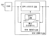
도 2 는 본 출원의 일 실시형태에 따른 국부 변환기 (204) 를 도시한다. 국부 변환기 (204) 는 도 1 의 국부 변환기들 (14) 중 하나를 나타낼 수도 있지만, 국부 변환기 (204) 는 본 출원의 범주를 벗어나지 않으면서 임의의 적절하게 구성된 에너지 발생 시스템으로 구현될 수도 있음을 이해할 것이다. 또한, PV 패널로 지칭되는 에너지 발생 디바이스 (202) 에 커플링된 것으로 도시되었지만, 국부 변환기 (204) 는 PV 패널의 단일 전지 또는 태양 전지 어레이의 패널의 서브세트에 커플링될 수도 있고, 또는 풍력 터빈, 연료 전지 등과 같은 다른 에너지 발생 디바이스 (202) 에 커플링될 수도 있음을 이해할 것이다.2 illustrates a
국부 변환기 (204) 는 전력 스테이지 (206) 및 국부 제어기 (208) 를 포함하고, 국부 제어기 (208) 는 MPPT 모듈 (210) 및 선택적인 통신 인터페이스 (212) 를 더 포함한다. 전력 스테이지 (206) 는, PV 패널 (202) 로부터 패널 전압 및 전류를 입력으로서 수신하고, 그 입력의 전압-전류 관계를 재형상화하여 출력 전압 및 전류를 발생시킬 수 있는 DC-DC 변환기를 포함할 수도 있다.The
국부 제어기 (208) 의 통신 인터페이스 (212) 는, 도 1 의 중앙 어레이 제어기 (110) 와 같은 중앙 어레이 제어기와 국부 변환기 (204) 사이에 통신 채널을 제공할 수 있다. 그러나, 국부 변환기 (204) 가 중앙 어레이 제어기와 통신하지 않는 실시형태에서, 통신 인터페이스 (212) 는 생략될 수도 있다.The
MPPT 모듈 (210) 은 패널 (202) 로부터 패널 전압 및 전류를 입력으로서 수신할 수 있고, 구현된 알고리즘에 의해 요구된다면, 전력 스테이지 (206) 로부터의 출력 전압 및 전류를 입력으로서 수신할 수 있다. 이 입력에 기초하여, MPPT 모듈 (210) 은 전력 스테이지 (206) 를 제어하기 위한 신호를 제공할 수 있다. 이 방식으로, 국부 제어기 (208) 의 MPPT 모듈 (210) 은 PV 패널 (202) 에 대한 MPPT 를 제공할 수 있다.The
MPPT 를 제공함으로써, MPPT 모듈 (210) 은 대응하는 패널 (202) 을 본질적으로 고정 동작 포인트 (즉, 패널 (202) 의 최대 전력 포인트에 대응하는 고정 전압 Vpan 및 전류 Ipan) 에서 기능하게 유지한다. 따라서, 소정의 고정 태양 광도에 대해, 정상 상태에서, 국부 변환기 (204) 에 대한 입력 전력은, 패널 (202) 의 상대적 또는 절대적 최대 전력 포인트에 대응하도록 고정된다 (즉, Ppan = Vpan·Ipan). 또한, 국부 변환기 (204) 는 비교적 높은 효율을 갖고, 따라서, 출력 전력은 그 입력 전력과 대략 동일하다 (즉, Pout ![]()
![]()
도 3 은 본 출원의 일 실시형태에 따른 국부 변환기 (204) 의 상세를 도시한다. 이 실시형태에서, 전력 스테이지 (206) 는 단일-인덕터, 4-스위치 동기화 버크-부스트 (buck-boost) 스위칭 조정기로서 구현되고, MPPT 모듈 (210) 은 전력 스테이지 조정기 (302), MPPT 제어 블록 (304) 및 2 개의 아날로그-디지털 변환기 (ADC; 306 및 308) 를 포함한다.3 shows details of a
ADC (306) 는 아날로그 패널 전압 Vpan 및 아날로그 패널 전류 Ipan 를 스케일링 및 양자화하여, 각각 디지털 패널 전압 및 디지털 패널 전류를 발생시킨다. 패널 전압 및 패널 전류로 도시되고 설명되었지만, Vpan 는 출력 디바이스 전압을 지칭할 수도 있고, Ipan 는 풍력 터빈, 연료 전지 등과 같은 임의의 다른 적절한 에너지 발생 디바이스 (202) 에 대한 출력 디바이스 전류를 지칭할 수도 있음을 이해할 것이다. MPPT 제어 블록 (304) 및 통신 인터페이스 (212) 에 커플링된 ADC (306) 는 또한, 디지털 패널 전압 및 전류 신호를 MPPT 제어 블록 (304) 및 통신 인터페이스 (212) 모두에 제공할 수 있다. 유사하게, ADC (308) 는 아날로그 출력 전압 및 아날로그 출력 전류를 스케일링 및 양자화하여, 각각 디지털 출력 전압 및 디지털 출력 전류를 발생시킬 수 있다. MPPT 제어 블록 (304) 및 통신 인터페이스 (212) 에 커플링된 ADC (308) 는 또한, 디지털 출력 전압 및 전류 신호를 MPPT 제어 블록 (304) 및 통신 인터페이스 (212) 모두에 제공할 수 있다. 통신 인터페이스 (212) 는 ADC (306) 에 의해 발생된 디지털 패널 전압 및 전류 신호, 및 ADC (308) 에 의해 발생된 디지털 출력 전압 및 전류 신호를 중앙 어레이 제어기에 제공할 수 있다.
전력 스테이지 조정기 (302) 에 커플링된 MPPT 제어 블록 (304) 은 ADC (306) 로부터의 디지털 패널 전압 및 전류와 ADC (308) 로부터의 디지털 출력 전압 및 전류를 수신할 수 있다. 이 디지털 신호들 중 적어도 일부에 기초하여, MPPT 제어 블록 (304) 은 전력 스테이지 조정기 (302) 에 대한 변환 비율 커맨드를 발생시킬 수 있다. 변환 비율 커맨드는 전력 스테이지 (206) 를 동작시키는데 이용하기 위한 전력 스테이지 조정기 (302) 에 대한 변환 비율을 포함한다. MPPT 제어 블록 (304) 이 디지털 출력 전압 및 전류가 아닌 디지털 패널 전압 및 전류에 기초하여 변환 비율 커맨드를 발생시킬 수 있는 실시형태에서, ADC (308) 는 디지털 출력 전압 및 전류를 MPPT 제어 블록 (304) 이 아닌 통신 인터페이스 (212) 에만 제공할 수도 있다.The
몇몇 실시형태에서, 전력 스테이지 조정기 (302) 는 버크-부스트 모드 제어 로직 및 디지털 펄스 폭 변조기를 포함한다. 전력 스테이지 조정기 (302) 는 MPPT 제어 블록 (304) 에 의해 제공된, 전력 스테이지 (206) 에 대한 펄스 폭 변조 (PWM) 신호의 변환 비율을 교정할 수 있는 변환 비율에 기초하여 펄스 폭 변조 (PWM) 를 발생시킴으로써 전력 스테이지 (206) 를 상이한 모드들에서 동작시킬 수 있다.In some embodiments, the power stage regulator 302 includes a buck-boost mode control logic and a digital pulse width modulator. The power stage regulator 302 is based on a conversion ratio that can correct the conversion ratio of the pulse width modulation (PWM) signal for the
전력 스테이지 조정기 (302) 는 전력 스테이지 (206) 에 커플링되고, 변환 비율에 기초하여 결정된 모드 및 듀티 사이클을 이용하여 전력 스테이지 (206) 를 동작시킴으로써 MPPT 제어 블록 (304) 으로부터의 변환 비율에 기초하여 전력 스테이지 (206) 를 동작시킬 수 있다. 전력 스테이지 (206) 가 버크-부스트 변환기로서 구현되는 도시된 실시형태에서, 전력 스테이지 (206) 에 대한 가능한 모드는 버크 모드, 부스트 모드, 버크-부스트 모드, 우회 모드 및 셧다운 모드를 포함할 수도 있다.The power stage regulator 302 is coupled to the
이 실시형태에서, 전력 스테이지 조정기 (302) 는, 변환 비율 CR 이 버크-부스트 범위 내에 있는 경우 버크-부스트 모드에서, CR 이 버크-부스트 범위보다 작은 경우 버크 모드에서, 및 CR 이 버크-부스트 범위보다 큰 경우 부스트 모드에서 전력 스테이지 (206) 를 동작시킬 수 있다. 버크-부스트 범위는, 실질적으로 1 과 동일한 값을 포함한다. 예를 들어, 특정한 실시형태에서, 버크-부스트 범위는 0.95 내지 1.05 를 포함할 수도 있다. 전력 스테이지 (206) 가 버크 모드인 경우, CR 이 최대 버크 변환 비율 CRbuck,max 보다 작으면, 전력 스테이지 조정기 (302) 는 전력 스테이지 (206) 를 버크 구성에서 완전하게 동작시킬 수 있다. 유사하게, 전력 스테이지 (206) 가 부스트 모드인 경우, CR 이 최소 부스트 변환 비율 CRboost,min 보다 크면, 전력 스테이지 조정기 (302) 는 전력 스테이지 (206) 를 부스트 구성에서 완전하게 동작시킬 수 있다.In this embodiment, the power stage regulator 302 is configured in buck-boost mode when the conversion ratio CR is within the buck-boost range, in buck mode when the CR is less than the buck-boost range, and in the buck-boost range. If greater, the
마지막으로, 변환 비율이 CRbuck,max 보다 크고 CRboost,min 보다 작은 경우, 전력 스테이지 조정기 (302) 는 전력 스테이지 (206) 를 버크 구성과 부스트 구성에서 교대로 동작시킬 수 있다. 이 상황에서, 전력 스테이지 조정기 (302) 는 버크 구성과 부스트 구성 사이에서 교번하기 위해 시분할 멀티플렉싱을 수행할 수도 있다. 따라서, 변환 비율이 CRbuck,max 에 더 근접할 경우, 전력 스테이지 조정기 (302) 는 전력 스테이지 (206) 를 부스트 구성에서보다 버크 구성에서 더 빈번하게 동작시킬 수도 있다. 유사하게, 변환 비율이 CRboost,min 에 더 근접할 경우, 전력 스테이지 조정기 (302) 는 전력 스테이지 (206) 를 버크 구성에서보다 부스트 구성에서 더 많이 동작시킬 수도 있다. 변환 비율이 CRbuck,max 과 CRboost,min 사이의 중점에 근접한 경우, 전력 스테이지 조정기 (302) 는 전력 스테이지 (206) 를 부스트 구성에서만큼 자주 버크 구성에서 동작시킬 수도 있다. 예를 들어, 전력 스테이지 (206) 가 버크-부스트 모드인 경우, 전력 스테이지 조정기 (302) 는 전력 스테이지 (206) 를 버크 구성과 부스트 구성에서 동작시키는 것을 균등하게 교번할 수도 있다.Finally, if the conversion ratio is greater than CR buck, max and less than CR boost, min , the power stage regulator 302 can operate the
도시된 실시형태에서, 전력 스테이지 (206) 는 인덕터 L 및 커패시터 C 뿐만 아니라 4 개의 스위치 (310a 내지 310d) 를 포함한다. 몇몇 실시형태에서, 스위치 (310) 는 N-채널 전력 MOSFET 을 포함할 수도 있다. 특정 실시형태에서, 이 트랜지스터들은 갈륨 나이트라이드-온-실리콘 디바이스를 포함할 수도 있다. 그러나, 스위치 (310) 는 본 출원의 범주를 벗어나지 않으면서 다른 방식으로 적절하게 구현될 수도 있음을 이해할 것이다. 또한, 전력 스테이지 (206) 는 스위치 (301)(예를 들어, 트랜지스터의 게이트) 를 구동시키기 위한 하나 이상의 드라이버 (도 3 에 미도시) 를 포함할 수도 있다. 예를 들어, 특정 실시형태에서, 제 1 드라이버가 전력 스테이지 조정기 (302) 와 트랜지스터 (310a 및 310b) 사이에 커플링되어, 트랜지스터 (310a 및 310b) 의 게이트를 구동시킬 수도 있고, 제 2 드라이버가 전력 스테이지 조정기 (302) 와 트랜지스터 (310c 및 310d) 사이에 커플링되어, 트랜지스터 (310c 및 310d) 의 게이트를 구동시킬 수도 있다. 이 실시형태에서, 전력 스테이지 조정기 (302) 에 의해 발생된 PWM 신호가 드라이버들에 제공되어, 그 PWM 신호에 기초하여 각각의 트랜지스터 (310) 의 게이트를 구동시킨다.In the illustrated embodiment, the
도시된 실시형태에서, 전력 스테이지 (206) 를 동작시킬 때, 전력 스테이지 조정기 (302) 는 디지털 펄스를 발생시켜 전력 스테이지 (206) 의 스위치 (310) 를 제어할 수 있다. 이하 설명하는 실시형태에서, 이 스위치 (310) 는 트랜지스터를 포함한다. 버크 구성에서, 전력 스테이지 조정기 (302) 는 트랜지스터 (310c) 를 턴오프시키고 트랜지스터 (310d) 를 턴온시킨다. 그 후, 전력 스테이지 (206) 가 버크 조정기로서 동작하도록, 펄스가 트랜지스터 (310a) 및 트랜지스터 (301b) 를 교대로 턴온 및 턴오프시킨다. 이 실시형태의 트랜지스터 (310a) 의 듀티 사이클은 MPPT 제어 블록 (304) 에 의해 발생된 변환 비율 커맨드에 포함된 듀티 사이클 D 와 동일하다. 부스트 모드에서, 전력 스테이지 조정기 (302) 는 트랜지스터 (301a) 를 턴온시키고 트랜지스터 (310b) 를 턴오프시킨다. 그 후, 전력 스테이지 (206) 가 부스트 조정기로서 동작하도록 펄스가 트랜지스터 (310c) 및 트랜지스터 (310d) 를 교대로 턴온 및 턴오프시킨다. 이 실시형태에서 트랜지스터 (310c) 의 듀티 사이클은 1-D 와 동일하다.In the illustrated embodiment, when operating the
버크-부스트 모드에서, 전력 스테이지 조정기 (302) 는 전술한 바와 같이 버크 구성과 부스트 구성 사이에서 시분할 멀티플렉싱을 수행한다. 전력 스테이지 조정기 (302) 는 트랜지스터 (310a 및 310b) 의 버크 스위치 쌍 및 트랜지스터 (310c 및 310d) 의 부스트 스위치 쌍에 대한 제어 신호를 발생시킨다. 트랜지스터 (310a) 에 대한 듀티 사이클은 CRbuck,max 에 대응하는 듀티 사이클로 고정되고, 트랜지스터 (310c) 에 대한 듀티 사이클은 CRboost,min 에 대응하는 듀티 사이클로 고정된다. 특정 시간 주기 동안 버크-구성과 부스트-구성 동작 사이의 비율은 D 에 선형으로 비례한다.In the buck-boost mode, the power stage regulator 302 performs time division multiplexing between the buck configuration and the boost configuration as described above. The power stage regulator 302 generates control signals for the buck switch pair of
출력 전압이 패널 전압에 근접한 경우, 전력 스테이지 (206) 는 버크-부스트 모드에서 동작된다. 이 상황에서, 도시된 실시형태에서는, 전압 스위치에 기인한 스트레스뿐만 아니라 인덕터 전류 리플 (ripple) 이 SEPIC 및 종래의 버크-부스트 변환기의 전류 리플보다 훨씬 작다. 또한, 도시된 전력 스테이지 (206) 는 종래의 버크-부스트 변환기에 비해 더 높은 효율을 달성한다.If the output voltage is close to the panel voltage, the
몇몇 실시형태에서는, 도 4 와 관련하여 이하 더 상세히 설명하는 바와 같이, MPPT 제어 클럭 (304) 이 4 개의 모드, 휴면, 트래킹, 홀딩 및 우회 중 하나에서 동작할 수 있다. 패널 전압이 미리 결정된 주 임계 전압보다 작은 경우, MPPT 제어 블록 (304) 은 휴면 모드에서 동작할 수도 있다. 휴면 모드인 동안, MPPT 제어 블록 (304) 은 트랜지스터 (310a 내지 310d) 가 턴오프되게 한다. 예를 들어, 몇몇 실시형태에서는, MPPT 제어 블록 (304) 이 변환 비율 커맨드를 발생시킬 수 있어서, MPPT 제어 블록 (304) 이 휴면 모드인 경우 전력 스테이지 조정기 (302) 로 하여금 트랜지스터 (310a 내지 310d) 를 턴오프시키게 할 수도 있다. 따라서, 전력 스테이지 (206) 는 셧다운 모드에 배치되고, 패널 (202) 은 우회되어, 패널이 구현되어 있는 태양 전지 시스템으로부터 패널 (202) 을 효과적으로 제거한다.In some embodiments, the
패널 전압이 주 임계 전압보다 크게 상승하는 경우, MPPT 제어 블록 (304) 은 트래킹 모드에서 동작할 수도 있다. 이 모드에서, MPPT 제어 블록 (304) 은 전력 스테이지 조정기 (302) 에 대한 최적의 변환 비율을 결정하기 위해 패널 (202) 에 대해 최대 전력 포인트 트래킹을 수행할 수도 있다. 또한, 이 모드에서, 전력 스테이지 조정기 (302) 는 현재 발생된 변환 비율 커맨드에 따라 전력 스테이지 (206) 를 버크 모드, 부스트 모드 또는 버크-부스트 모드에 배치한다.If the panel voltage rises above the main threshold voltage, the
또한, 몇몇 실시형태에서, MPPT 제어 블록 (304) 으로 하여금 전력 스테이지 (206) 를 셧다운 모드로 유지하게 하기 위해, MPPT 제어 블록 (304) 은 또한, 중앙 어레이 제어기에서 구현된 제어 프로그램과 같은 임의의 적절한 제어 프로그램 또는 시스템의 오퍼레이터에 의해 변형될 수도 있는 셧다운 레지스터를 포함할 수도 있다. 이 실시형태에서, MPPT 제어 블록 (304) 은, (i) 패널 전압이 주 임계 전압을 초과하고, (ii) MPPT 제어 블록 (304) 이 전력 스테이지 (206) 를 셧다운 모드 밖으로 이동시킬 수도 있는 것을 셧다운 레지스터가 나타낼 때까지, 트래킹 모드에서 동작하는 것을 시작하지 않는다.In addition, in some embodiments, in order to cause
MPPT 제어 블록 (304) 이 최적의 변환 비율을 발견한 경우, MPPT 제어 블록 (304) 은 미리 정의된 시간 주기 동안 홀딩 모드에서 동작할 수도 있다. 이 모드에서, MPPT 제어 블록 (304) 은 트래킹 모드에서 최적의 변환 비율로 결정된 것과 동일한 변환 비율을 전력 스테이지 조정기 (302) 에 제공하는 것을 계속할 수도 있다. 또한 이 모드에서는, 트래킹 모드에서와 같이, 변환 비율 커맨드에서 제공된 최적의 변환 비율에 따라 전력 스테이지 (206) 가 버크 모드, 부스트 모드 또는 버크-부스트 모드에 배치된다. 미리 정의된 시간 주기가 경과한 후, MPPT 제어 블록 (304) 은 트래킹 모드로 복귀하여, 최적의 변환 비율이 변경되지 않는 것을 보장할 수도 있고, 또는 패널 (202) 에 대한 조건이 변경된 경우 새로운 최적의 변환 비율을 발견할 수도 있다.If the
이하, 도 5 내지 도 8 과 관련하여 더 상세히 설명하는 바와 같이, 태양 전지 어레이 내의 패널 (202) 과 같은 패널들 각각이 균일한 조사 (illumination) 하에 있고 패널 (202) 사이에 미스매치가 존재하지 않는 경우, 중앙 어레이 제어기는 MPPT 제어 블록 (304) 및 그에 따른 전력 스테이지 (206) 를 우회 모드에 배치할 수도 있다. 우회 모드에서, 몇몇 실시형태에서는, 패널 전압이 출력 전압과 동일하도록 트랜지스터 (310a 및 310d) 가 턴온되고, 트랜지스터 (310b 및 310c) 가 턴오프된다. 다른 실시형태에서는, 입력 포트를 출력 포트에 커플링하여 출력 전압이 패널 전압과 동일해지게 하는 선택적인 스위치 (312) 가 전력 스테이지 (206) 내에 포함될 수도 있다. 이 방식으로, MPPT 가 국부적으로 요구되지 않는 경우, 국부 변환기 (204) 는 시스템으로부터 본질적으로 제거되어, 국부 변환기 (204) 와 관련된 손실을 감소시키고 수명을 증가시켜 효율을 최대화할 수도 있다.5-8, each of the panels, such as
따라서, 이하 설명하는 바와 같이, MPPT 제어 블록 (304) 은 휴면 모드에서 동작할 수 있고 전력 스테이지 (206) 를 셧다운 모드에 배치할 수 있어서, 패널 (202) 이 우회되게 할 수도 있다. MPPT 제어 블록 (304) 은 또한 트래킹 모드 또는 홀딩 모드에서 동작할 수도 있다. 이 모드들 중 하나에서, MPPT 제어 블록 (304) 은 전력 스테이지 (206) 를 버크 모드, 부스트 모드 및 버크-부스트 모드 중 하나에 배치할 수 있다. 마지막으로, MPPT 제어 블록 (304) 은 우회 모드에서 동작할 수 있고 전력 스테이지 (206) 를 우회 모드에 배치할 수 있어서, 패널 (202) 이 어레이 내의 다른 패널 (202) 에 직접 커플링되게 하면서 국부 변환기 (204) 가 우회되게 할 수도 있다.Thus, as described below, the
이 방식으로 국부 변환기 (204) 를 우회시킴으로써, 패널 (202) 을 포함하는 패널의 스트링에 대한 스트링 전류는 개별 패널 전류에 대해 독립적이다. 대신에, 스트링 전류는 스트링 전압 및 총 스트링 전력에 의해 설정된다. 또한, 차양되지 않은 패널 (202) 은 스트링 내의 다른 패널의 차양 조건과 무관하게 피크 전력 포인트에서 동작을 계속할 수도 있다.By bypassing the
대안적 실시형태에서, MPPT 제어 블록 (304) 이 최적의 변환 비율을 발견한 경우, 최적의 변환 비율이 전력 스테이지 (206) 에 대한 버크-부스트 모드에 대응하면, MPPT 제어 블록 (304) 은 홀딩 모드 대신 우회 모드에서 동작할 수도 있다. 버크-부스트 모드에서, 출력 전압은 패널 전압에 근접한다. 따라서, 패널 (202) 은 국부 변환기 (204) 를 우회함으로써 최대 전력 포인트에 근접하여 동작될 수도 있고, 이것은 효율을 증가시킨다. 전술한 실시형태에서와 같이, MPPT 제어 블록 (304) 은 최적의 변환 비율이 버크-부스트 모드 범위 내에 유지되고 있는지를 확인하기 위해 우회 모드로부터 트래킹 모드로 주기적으로 복귀할 수도 있다.In an alternative embodiment, when the
몇몇 실시형태에서, MPPT 제어 블록 (304) 은 전력 스테이지 (206) 의 트랜지스터, 인덕터 및 커패시터 상의 스트레스를 회피하기 위해, 전력 스테이지 조정기 (302) 에 대해 변환 비율을 통상적인 계단식 변량과는 반대로 점진적으로 조정할 수도 있다. 몇몇 실시형태에서, MPPT 제어 블록 (304) 은 상이한 MPPT 기술을 구현하여, 변환 비율 대신 패널 전압 또는 컨덕턴스를 조정할 수 있다. 또한, MPPT 제어 블록 (304) 은 동적 입력 전압 조정을 위해 변환 비율 대신 기준 전압을 조정할 수 있다.In some embodiments, MPPT control block 304 incrementally converts the conversion ratio for power stage regulator 302 as opposed to a typical stepped variable to avoid stress on the transistors, inductors, and capacitors of
또한, MPPT 제어 블록 (304) 은 전력 스테이지 (206) 에 대한 셧다운 모드와 다른 모드들 사이에서 비교적 빠르고 평활한 전이를 가능하게 할 수 있다. MPPT 제어 블록 (304) 은, 변환 비율 등과 같은 이전의 최대 전력 포인트 상태를 저장할 수 있는 비휘발성 메모리를 포함할 수도 있다. 이 실시형태에서, MPPT 제어 블록 (304) 이 휴면 모드로 전이하는 경우, 최대 전력 포인트 상태는 이 비휘발성 메모리에 저장된다. MPPT 제어 블록 (304) 이 후속적으로 트래킹 모드로 리턴하는 경우, 저장된 최대 전력 포인트 상태는 초기 최대 전력 포인트 상태로서 이용될 수도 있다. 이 방식으로, 셧다운과 다른 모드들 사이의 전이 시간은 전력 스테이지 (206) 에 대해 현저하게 감소될 수도 있다.In addition, the
몇몇 실시형태에서, MPPT 제어 블록 (304) 은 또한 국부 변환기 (204) 에 대해 과도 전력 및/또는 과도 전압 보호를 제공할 수 있다. 신호 Vpan 및 Ipan 가 ADC (306) 를 통해 MPPT 제어 블록 (304) 쪽으로 공급되기 때문에, MPPT 제어 블록 (304) 은 최대 전력을 추출하려 시도한다. 전력 스테이지 (206) 출력에서 개방 회로가 존재하면, 국부 변환기 (204) 에 대한 출력 전압은 최대값에 도달한다. 따라서, 과도 전력 보호를 위해, 국부 변환기 (204) 의 출력 전류는 MPPT 제어 블록 (304) 을 턴온 및 턴오프시키기 위한 신호로서 이용될 수도 있다. 이 실시형태에서, 출력 전류가 너무 낮게 감소되면, 패널 전압이 출력 전압과 대략 동일해지도록 변환 비율은 MPPT 제어 블록 (304) 에 의해 설정될 수도 있다.In some embodiments,
과도 전압 보호에서, MPPT 제어 블록 (304) 은, 그 MPPT 제어 블록 (304) 이 초과하지 않을, 변환 비율 커맨드에 대한 최대 변환 비율을 가질 수도 있다. 따라서, 변환 비율이 과거의 최대 변환 비율보다 크게 계속되면, MPPT 제어 블록 (304) 은 변환 비율을 최대값으로 제한한다. 이것은, 출력 전압이 대응 최대값을 넘어 증가하지 않을 것을 보장한다. 최대 변환 비율의 값은 고정형일 수도 있고, 또는 적응형일 수도 있다. 예를 들어, 적응형 변환 비율 제한은, 패널 전압을 감지하고, 전력 스테이지 (206) 의 변환 비율에 따라 그 변환 비율의 다음의 프로그래밍된 값에 대응하는 출력 전압의 추정을 연산함으로써 달성될 수도 있다.In transient voltage protection, the
또한, 도시된 실시형태에서, 전력 스테이지 (206) 는 선택적인 일방향 스위치 (314) 를 포함한다. 이 선택적인 스위치 (314) 는, 전력 스테이지 (206) 가 셧다운 모드인 경우 패널 (202) 이 우회되는 것을 허용하여, 그 패널 (202) 은 어레이로부터 제거되고 다른 패널들 (202) 은 동작을 계속할 수 있게 하기 위해 포함될 수도 있다. 특정 실시형태에서, 일방향 스위치 (314) 는 다이오드를 포함할 수도 있다. 그러나, 이 일방향 스위치 (314) 는 본 출원의 범주를 벗어나지 않으면서 임의의 다른 적절한 타입의 일방향 스위치를 포함할 수도 있음을 이해할 것이다.In addition, in the illustrated embodiment, the
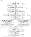
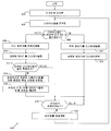
도 4 는 본 출원의 일 실시형태에 따른 국부 변환기 (204) 에서 MPPT 를 구현하는 방법 (400) 을 도시한다. 이 방법 (400) 의 실시형태는 오직 예시를 위한 것이다. 본 출원의 범주를 벗어나지 않으면서 방법 (400) 의 다른 실시형태가 구현될 수도 있다.4 shows a
방법 (400) 은 MPPT 제어 블록 (304) 이 휴면 모드에서 동작하는 것으로 시작한다 (단계 401). 예를 들어, MPPT 제어 블록 (304) 은 변환 비율 커맨드를 발생시켜, 전력 스테이지 조정기 (302) 로 하여금 전력 스테이지 (206) 의 트랜지스터 (310a 내지 310d) 를 턴오프시켜, 전력 스테이지 (206) 를 셧다운 모드에 배치하고 패널 (202) 을 우회시킬 수도 있다.The
휴면 모드에서, MPPT 제어 블록 (304) 은 패널 전압 Vpan 을 모니터링하고, 그 패널 전압을 주 임계 전압 Vth 와 비교한다 (단계 402). 예를 들어, ADC (306) 는 패널 전압을 아날로그 신호로부터 디지털 신호로 변환하고, 디지털 패널 전압과의 비교를 위해 주 임계 전압을 저장한 MPPT 제어 블록 (304) 에 그 디지털 패널 전압을 제공한다.In the sleep mode, the MPPT control block 304 monitors the panel voltage V pan and compares the panel voltage with the main threshold voltage V th (step 402). For example, the
패널 전압이 주 임계 전압보다 낮게 유지되는 동안 (단계 402), MPPT 제어 블록 (304) 은 휴면 모드에서 동작을 계속한다. 또한, 전술한 바와 같이, 전력 스테이지 (206) 가 셧다운 모드로 유지되는 것으로 셧다운 레지스터가 나타내는 경우, MPPT 제어 블록 (304) 은 휴면 모드로 유지될 수도 있다. 그러나, 패널 전압이 주 임계 전압을 초과하면 (단계 402), MPPT 제어 블록 (304) 은, 초기 변환 비율을 포함하는, 전력 스테이지 (206) 를 동작시키기 위한 변환 비율 커맨드를 발생시킨다 (단계 403). 예를 들어, 일 실시형태에서, MPPT 제어 블록 (304) 은 1 의 변환 비율로 시작할 수도 있다. 대안적으로, MPPT 제어 블록 (304) 은 이전의 트래킹 모드 동안 결정된 최적의 변환 비율을 저장할 수도 있다. 이 실시형태에서, MPPT 제어 블록 (304) 은 변환 비율을, 이전에 결정된 최적의 변환 비율과 동일해지도록 초기화할 수도 있다. 또한, MPPT 제어 블록 (304) 에 의해 발생된 변환 비율 커맨드는, 그 초기 변환 비율을 이용하여 전력 스테이지 (206) 를 동작시키는 전력 스테이지 조정기 (302) 에 제공된다.While the panel voltage is kept below the main threshold voltage (step 402), the
이 때, MPPT 제어 블록 (304) 은 패널 전류 Ipan 및 출력 전류 Iout 를 모니터링하고, 그 패널 전류 및 출력 전류를 임계 전류 Ith 와 비교한다 (단계 404). 예를 들어, ADC (306) 가 패널 전류를 아날로그 신호로부터 디지털 신호로 변환하고 디지털 패널 전류를 MPPT 제어 블록 (304) 에 제공할 수도 있고, ADC (308) 가 출력 전류를 아날로그 신호로부터 디지털 신호로 변환하고, 그 디지털 출력 전류를, 디지털 패널 전류 및 디지털 출력 전류와의 비교를 위해 임계 전류를 저장하는 MPPT 제어 블록 (304) 에 제공할 수도 있다. 이 전류들 Ipan 및 Iout 중 적어도 하나가 임계 전류보다 낮게 유지되는 동안 (단계 404), MPPT 제어 블록 (304) 은 전류 레벨의 모니터링을 계속한다. 그러나, 이 전류들 모두가 임계 전류를 초과하면 (단계 404), MPPT 제어 블록 (304) 은, 초기에 트래킹 변수 T 를 1 로 설정하고 카운트를 초기화하는 것을 포함하는 트래킹 모드에서 동작하기 시작한다 (단계 406).At this time, the MPPT control block 304 monitors the panel current I pan and the output current I out , and compares the panel current and output current with the threshold current I th (step 404). For example, the
도 4 의 방법 (400) 에는 도시되지 않았지만, MPPT 제어 블록 (304) 은 트래킹 모드인 동안 패널 전압의 모니터링을 계속할 수도 있고, 그 패널 전압을, 주 임계 전압보다 작은 보조 임계 전압과 비교할 수도 있음을 이해할 것이다. 패널 전압이 보조 임계 전압보다 작게 감소하면, MPPT 제어 블록 (304) 은 휴면 모드로 복귀할 수도 있다. 주 임계 전압보다 작은 보조 임계 전압을 이용함으로써, MPPT 제어 블록 (304) 이 휴면 모드와 트래킹 모드 사이에서 빈번하게 스위칭되는 것을 방지하는 잡음 내성이 MPPT 제어 블록 (304) 에 제공된다.Although not shown in the
트래킹 변수의 값을 설정하고 카운트를 초기화한 후, MPPT 제어 블록 (304) 은 패널 (202) 에 대한 초기 전력을 계산한다 (단계 408). 예를 들어, ADC (306) 는 디지털 패널 전류 및 패널 전압 신호 (Ipan 및 Vpan) 를 MPPT 제어 블록 (304) 에 제공할 수도 있고, 그 후, MPPT 제어 블록 (304) 은 이 신호들을 함께 승산하여 디바이스 (또는 패널) 전력에 대한 초기값 (Ipan·Vpan) 을 결정한다.After setting the value of the tracking variable and initializing the count,
초기 전력을 계산한 후, MPPT 제어 블록 (304) 은 변환 비율을 제 1 방향으로 변형하고, 그 변형된 변환 비율을 포함하는 변환 비율 커맨드를 발생시킨다 (단계 410). 예를 들어, 몇몇 실시형태에서, MPPT 제어 블록 (304) 은 변환 비율을 증가시킬 수도 있다. 다른 실시형태에서, MPPT 제어 블록 (304) 은 변환 비율을 감소시킬 수도 있다. 시스템이 안정될 시간을 부여한 후, MPPT 제어 블록 (304) 은 패널 (202) 에 대한 현재 전력을 계산한다 (단계 412). 예를 들어, ADC (306) 는 디지털 패널 전류 및 패널 전압 신호를 MPPT 제어 블록 (304) 에 제공할 수도 있고, 그 후, MPPT 제어 블록 (304) 은 이 신호들을 함께 승산하여 패널 전력에 대한 현재값을 결정한다.After calculating the initial power, the
그 후, MPPT 제어 블록 (304) 은 현재의 계산된 전력을, 초기에는 초기 전력인 이전에 계산된 전력과 비교한다 (단계 414). 현재 전력이 이전의 전력보다 크면 (단계 414), MPPT 제어 블록 (304) 은 변환 비율을 이전의 변형과 동일한 방향으로 변형하고, 업데이트된 변환 비율 커맨드를 발생시킨다 (단계 416). 몇몇 실시형태에서, 변환 비율은 동일 사이즈의 증분으로 더 높거나 낮게 변형된다. 다른 실시형태에서, 변환 비율은 선형 또는 비선형의 증분으로 더 높거나 낮게 변형되어 시스템 응답을 최적화시킬 수도 있다. 예를 들어, 변환 비율이 최적값으로부터 멀리 떨어져 있으면, 초기에는 더 큰 증분을 이용하고 최적값에 접근함에 따라 후속적으로 더 작은 증분을 이용하는 것이 몇몇 시스템에서 바람직할 수도 있다.The MPPT control block 304 then compares the current calculated power with the previously calculated power that is initially initial power (step 414). If the current power is greater than the previous power (step 414), the
MPPT 제어 블록 (304) 은 또한, 트래킹 변수 T 가 1 과 동일한지 여부를 결정하며, 이것은, 변환 비율이 이전의 계산 전에 계산을 위해 변형되었을 때 변환 비율이 그 이전의 계산과 동일한 방향으로 변형되었음을 나타낸다 (단계 418). 따라서, T 가 1 과 동일한 경우, 패널 전력은 변환 비율의 이전의 변형에 의해 동일 방향으로 증가한다. 이 경우, 시스템이 안정될 시간을 부여한 후, MPPT 제어 블록 (304) 은 그 패널 (202) 에 대한 현재 전력을 다시 계산하고 (단계 412), 이를 이전의 전력과 비교한다 (단계 414). 그러나, T 가 1 과 동일하지 않은 것으로 MPPT 제어 블록 (304) 이 결정하면, 이것은, 변환 비율이 이전의 계산 전에 계산을 위해 변형되었을 때 변환 비율이 이전 계산의 반대 방향으로 변형되었음을 나타내고 (단계 418), MPPT 제어 블록 (304) 은 T 를 1 로 설정하고 카운트를 증분시킨다 (단계 420).The
그 후, MPPT 제어 블록 (304) 은, 카운트가 카운트 임계값 Cth 을 초과했는지 여부를 결정한다 (단계 422). 카운트의 현재의 값이 카운트 임계값을 초과하지 않았으면 (단계 422), 시스템이 안정될 시간을 부여한 후, MPPT 제어 블록 (304) 은 그 패널 (202) 에 대한 현재의 전력을 다시 계산하고 (단계 412), 이를 이전의 전력과 비교하여 (단계 414), 패널 전력이 증가중인지 감소중인지 여부를 결정한다.The MPPT control block 304 then determines whether the count has exceeded the count threshold C th (step 422). If the current value of the count did not exceed the count threshold (step 422), after giving the system time to stabilize, the
현재 전력이 이전의 전력보다 크지 않은 것으로 MPPT 제어 블록 (304) 이 결정하면 (단계 414), MPPT 제어 블록 (304) 은 그 변환 비율을 이전의 변형의 반대 방향으로 변형하고, 업데이트된 변환 비율 커맨드를 발생시킨다 (단계 424). MPPT 제어 블록 (304) 은 또한, 트래킹 변수 T 가 2 와 동일한지 여부를 결정하고, 이것은, 변환 비율이 이전의 계산 전에 계산을 위해 변형되었을 때 그 이전의 계산의 반대 방향으로 변형된 것을 나타낸다 (단계 426). 이 경우, 시스템이 안정될 시간을 부여한 후, MPPT 제어 블록 (304) 은 그 패널 (202) 에 대한 현재의 전력을 다시 계산하고 (단계 412), 이를 이전의 전력과 비교한다 (단계 414).If the
그러나, T 가 2 와 동일하지 않은 것으로 MPPT 제어 블록 (304) 이 결정하면, 이것은, 변환 비율이 이전의 계산 전에 계산을 위해 변형되었을 때 변환 비율이 이전 계산과 동일한 방향으로 변형되었음을 나타내고 (단계 426), MPPT 제어 블록 (304) 은 T 를 2 로 설정하고 카운트를 증분시킨다 (단계 428). 그 후, 전술한 바와 같이, MPPT 제어 블록 (304) 은 카운트가 카운트 임계값 Cth 를 초과했는지 여부를 결정한다 (단계 422).However, if the
카운트가 카운트 임계값을 초과했다면 (단계 422), 이것은, 변환 비율이 카운트 임계값보다 큰 횟수 동안 제 1 방향 및 제 2 방향으로 교대로 변형되었음을 나타내고, MPPT 제어 블록 (304) 은, 그 패널 (202) 에 대한 최대의 전력 포인트에 대응하는 최적의 변환 비율을 발견하고, MPPT 제어 블록 (304) 은 홀딩 모드에서 동작하는 것을 시작한다 (단계 430).If the count has exceeded the count threshold (step 422), this indicates that the conversion ratio has been altered alternately in the first and second directions for a number of times greater than the count threshold, and the
홀딩 모드 동안, MPPT 제어 블록 (304) 은 타이머를 설정하고 카운트를 재초기화할 수도 있다 (단계 432). 타이머가 만료된 경우 (단계 434), MPPT 제어 블록 (304) 은 트래킹 모드로 복귀하고 (단계 436), 현재의 전력을 계산하여 (단계 412), MPPT 제어 블록 (304) 이 이전에 트래킹 모드인 시점에 계산된 최후의 전력과 비교한다 (단계 414). 이 방식으로, MPPT 제어 블록 (304) 은, 최적의 변환 비율이 변경되지 않은 것을 보장할 수도 있고 또는 그 패널 (202) 에 대한 조건이 변경된 경우 다른 최적의 변환 비율을 발견할 수도 있다.During the holding mode, the
도 4 는 에너지 발생 디바이스 (202) 에 대한 최대 전력 포인트를 트래킹하는 방법의 일예를 도시하며, 이 방법 (400) 에 대한 다양한 변경예가 행해질 수도 있다. 예를 들어, 이 방법 (400) 은 태양 전지 패널을 참조하여 설명되었지만, 이 방법 (400) 은 풍력 터빈, 연료 전지 등과 같은 다른 에너지 발생 디바이스 (202) 에 대해 구현될 수도 있다. 또한, 이 방법은 도 3 의 MPPT 제어 블록 (304) 을 참조하여 설명되었지만, 이 방법 (400) 은 본 출원의 범주를 벗어나지 않으면서 임의의 적절하게 구성된 MPPT 제어 블록에서 구현될 수도 있음을 이해할 것이다. 또한, 몇몇 실시형태에서, 최적의 변환 비율이 전력 스테이지 (206) 에 대한 버크-부스트 모드에 대응하는 것으로 MPPT 제어 블록 (304) 이 결정하면, MPPT 제어 블록 (304) 은 단계 430 에서 홀딩 모드 대신에 휴면 모드에서 동작할 수도 있다. 이 실시형태에서, 휴면 모드 동안 타이머가 만료된 후의 시간량은 홀딩 모드 동안 타이머와 연관된 시간량과 동일할 수도 있고 또는 상이할 수도 있다. 또한, 일련의 단계들로 도시되었지만, 방법 (400) 의 단계들은 중첩되거나, 병렬로 발생하거나, 다수회 발생하거나, 상이한 순서로 발생할 수도 있다.4 shows an example of a method of tracking the maximum power point for the
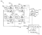
도 5 는, 본 출원의 일 실시형태에 따른 에너지 발생 시스템 (500) 에 대해, 중앙집중형 MPPT 와 분산형 MPPT 사이에서 선택할 수 있는 중앙집중형 어레이 제어기 (510) 및 복수의 에너지 발생 디바이스 (502) 를 포함하는 에너지 발생 시스템 (500) 을 도시한다. 도시된 실시형태에서, 이 에너지 발생 시스템은, 각각 대응하는 국부 변환기 (504) 에 커플링되는 태양 전지 패널 (502) 의 어레이를 포함하는 태양 전지 시스템 (500) 으로 지칭된다.FIG. 5 illustrates a
각각의 국부 변환기 (504) 는 전력 스테이지 (506) 및 국부 제어기 (508) 를 포함한다. 또한, 몇몇 실시형태에서, 각각의 국부 변환기 (504) 는 스위치 (312) 와 같은 선택적인 내부 스위치를 통해 우회될 수도 있다. 우회되는 경우, 국부 변환기 (504) 의 출력 전압은 실질적으로 입력 전압과 동일하게 된다. 이 방식으로, 국부 변환기 (504) 의 동작과 연관된 손실은, 국부 변환기 (504) 가 불필요한 경우에도 최소화되거나 제거될 수도 있다.Each local converter 504 includes a power stage 506 and a local controller 508. In addition, in some embodiments, each local converter 504 may be bypassed through an optional internal switch, such as
중앙 어레이 제어기 (510) 에 부가하여, 시스템 (500) 의 도시된 실시형태는 또한 변환 스테이지 (512), 그리드 (514) 및 데이터 버스 (506) 를 포함할 수도 있다. 중앙 어레이 제어기 (510) 는 진단 모듈 (520), 제어 모듈 (525) 및 선택적인 변환 스테이지 (CS) 최적화기 (530) 를 포함한다. 또한, 도시된 실시형태는 변환 스테이지 (512) 에 글로벌 제어기 (540) 를 제공한다. 그러나, 글로벌 제어기 (540) 는 변환 스테이지 (512) 대신에 중앙 어레이 제어기 (510) 에 구현될 수도 있음을 이해할 것이다. 또한, CS 최적화기 (530) 는 중앙 어레이 제어기 (510) 대신에 변환 스테이지 (512) 에 구현될 수도 있다.In addition to the
몇몇 실시형태에서, 패널 (502) 및 국부 변환기 (504) 는 도 1 의 패널 (102) 및 국부 변환기 (104), 및/또는 도 2 또는 도 3 의 패널 (202) 및 국부 변환기 (204) 를 나타낼 수도 있고, 중앙 어레이 제어기 (510) 는 도 1 의 중앙 어레이 제어기 (110) 를 나타낼 수도 있고/있거나, 변환 스테이지 (512) 는 도 1 의 DC-AC 변환기 (112) 를 나타낼 수도 있다. 또한, 진단 모듈 (520) 및 제어 모듈 (525) 은 각각 도 1 의 진단 모듈 (120) 및 제어 모듈 (125) 를 나타낼 수도 있다. 그러나, 시스템 (500) 의 컴포넌트들은 임의의 적절한 방식으로 구현될 수도 있음을 이해할 것이다. 변환 스테이지 (512) 는 DC-AC 변환기, 배터리 충전기 또는 다른 에너지 저장 디바이스 또는 임의의 다른 적절한 컴포넌트를 포함할 수도 있다. 그리드 (514) 는 태양 전지 시스템 (500) 에 의해 발생된 에너지에 기초하여 동작할 수 있는 임의의 적절한 로드를 포함할 수도 있다.In some embodiments, panel 502 and local converter 504 replace panel 102 and local converter 104 of FIG. 1 and / or
국부 제어기 (508) 각각은 데이터 버스 (516) 를 통해, 또는 대안적으로는 무선 링크를 통해, 대응하는 패널 (502) 에 대한 디바이스 데이터 및 국부 변환기 데이터를 중앙 어레이 제어기 (510) 에 제공할 수 있다. 이 데이터에 기초하여, 진단 모듈 (520) 은, 패널 (502) 이 준-이상적 조건 하에서 동작중인지 여부, 즉, 패널 (502) 이 미스매치되지 않고 서로 실질적으로 동일한 양만큼 조사되고 있는지 여부를 결정할 수도 있다. 이 상황에서, 진단 모듈 (520) 은 제어 모듈 (525) 로 하여금 시스템 (500) 을 중앙집중형 MPPT (CMPPT) 모드에 두도록 프롬프트할 수 있다. 이를 달성하기 위해, 제어 모듈 (525) 은 국부 변환기 (504) 를 우회 모드에서 동작시킴으로써 국부 변환기 (504) 를 디스에이블하기 위해 디스에이블 신호를 데이터 버스 (516) 를 통해 국부 제어기 (508) 각각에 전송할 수 있다. 제어 모듈 (525) 은 또한 인에이블 신호를 글로벌 제어기 (540) 에 전송할 수 있다.Each of the local controllers 508 can provide the
우회 모드에서, 국부 제어기 (508) 는 더 이상 MPPT 를 수행하지 않고, 전력 스테이지 (506) 의 출력 전압은 패널 (502) 로부터의 패널 전압과 실질적으로 동일하게 된다. 따라서, 국부 변환기 (504) 를 동작시키는 것과 연관된 손실은 최소화되고, 시스템 (500) 의 효율은 최대화된다. 국부 변환기 (504) 가 우회 모드에서 동작중인 경우, 글로벌 제어기 (540) 는 패널 (502) 의 어레이에 대해 CMPPT 를 수행할 수 있다.In the bypass mode, the local controller 508 no longer performs MPPT, and the output voltage of the power stage 506 becomes substantially the same as the panel voltage from the panel 502. Thus, the losses associated with operating local converter 504 are minimized and the efficiency of
진단 모듈 (520) 은 또한, 패널 (502) 중 일부가 차양되거나 미스매치될 수도 있는지 여부 (즉, 일부 패널 (502) 이 어레이 내의 다른 패널 (502) 에 비해 상이한 특성을 갖는지 여부) 를 결정할 수 있다. 이 상황에서, 진단 모듈 (502) 은 제어 모듈 (525) 로 하여금 시스템 (500) 을 분산형 MPPT (DMPPT) 모드에 두도록 프롬프트할 수 있다. 이를 달성하기 위해, 제어 모듈 (525) 은, 국부 변환기 (504) 의 정규의 동작을 허용함으로써 국부 변환기 (504) 를 인에이블하기 위해 인에이블 신호를 데이터 버스 (516) 를 통해 국부 제어기 (508) 각각에 전송할 수 있다. 제어 모듈 (525) 은 또한 디스에이블 신호를 글로벌 제어기 (540) 에 전송할 수 있다.The
패널 (502) 중 일부가 차양된 경우, 진단 모듈 (520) 은 또한 차양된 패널 (502) 중 일부가 부분적으로 차양될 수도 있음을 결정할 수 있다. 이 상황에서, 제어 모듈 (525) 로 하여금 시스템을 DMPPT 모드에 두도록 프롬프트하는 것에 부가하여, 진단 모듈 (520) 은 또한, 부분적으로 차양된 패널 (502) 에 대한 국부 제어기 (508) 가 국부 최대값이 아닌 실제 최대 전력 포인트를 발견하는 것을 보장하기 위해 시스템 (500) 의 완전한 진단 스캔을 수행할 수도 있다. 에너지 발생 디바이스 (502) 가 풍력 터빈을 포함하는 실시형태에서, 진단 모듈 (502) 은, 바람 패턴의 변화, 언덕 또는 바람을 방해하는 다른 구조, 또는 다른 바람에 영향을 주는 조건에 기인하여, 풍력 터빈의 일부가 "차양"되는지 여부를 결정할 수도 있다.If some of the panels 502 are shaded, the
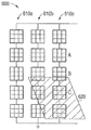
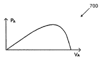
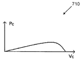
태양 전지 시스템 (500) 에 대한 부분적으로 차양된 상황이 도 6 및 도 7a 내지 7c 에 도시되어 있다. 도 6 은 부분적으로 차양된 조건 하의 태양 전지 어레이 (600) 를 도시한다. 도 7a 내지 7c 는, 도 6 의 태양 전지 패널 중 3 개에 대응하는 전압-전력 특성을 도시하는 그래프 (700, 705 및 710) 이다.A partially shaded situation for the
도시된 어레이 (600) 는 태양 전지 패널의 3 개의 스트링 (610) 을 포함한다. 스트링 (610c) 내의 패널 중 3 개가 패널 A, 패널 B 및 패널 C 로서 라벨링되어 있다. 3 개의 패널은 도 5 의 패널 (502) 또는 임의의 다른 적절히 구성된 태양 전지 시스템 내의 패널을 나타낼 수도 있다. 패널 중 몇몇은 차양된 영역 (620) 에 의해 완전하게 또는 부분적으로 커버된다.The illustrated
도시된 예에서, 패널 A 는 완전하게 조사되고, 패널 B 는 부분적으로 차양되고, 패널 C 는 차양 영역 (620) 에 의해 완전하게 차양된다. 도 7a 의 그래프 (700) 의 전압-전력 특성은 패널 A 에 대응하고, 도 7b 의 그래프 (705) 의 전압-전력 특성은 패널 B 에 대응하고, 도 7c 의 그래프 (710) 의 전압-전력 특성은 패널 C 에 대응한다.In the example shown, panel A is fully illuminated, panel B is partially shaded, and panel C is completely shaded by
따라서, 그래프 (705) 에 도시된 바와 같이, 부분적으로 차양된 패널 B 는 실제 최대 전력 포인트 (725) 와는 상이한 국부 최대값 (720) 을 갖는다. 중앙 어레이 제어기 (510) 의 진단 모듈 (520) 은, 패널 B 가 부분적으로 차양되었을 수도 있다고 결정할 수 있고, 패널 B 가 국부 최대값 (720) 의 반대로 실제 최대 전력 포인트 (725) 에서 국부 제어기 (508) 에 의해 동작되는 것을 보장하기 위해 완전한 진단 스캔을 수행할 수 있다. 실제 최대 전력 포인트 대신에 포인트 (720) 와 같은 국부 최대 전력 포인트에서 동작중인 패널 (502) 은 "저조한 수행" 패널 (502) 로 지칭된다.Thus, as shown in
특정 실시형태에서, 진단 모듈 (520) 은 다음과 같이 부분적으로 차양된 패널 (502) 을 식별할 수도 있다. 먼저, 진단 모듈 (520) 은, 패널 1, ..., N 이 동일한 특성을 갖는 고려된 어레이 내의 패널 (502) 의 서브세트인 것으로 가정하고, Ppan,i 가 그 세트 [1, ..., N] 에 속하는 i 번째 패널 (502) 의 출력 전력인 것으로 가정한다. 그러면,In a particular embodiment, the
Ppan,max ≥ Ppan,i ≥ Ppan,min P pan, max ≥ P pan, i ≥ P pan, min
이고, Ppan,max 는 최상으로 수행하는 패널 (502) 의 출력 전력이고, Ppan,min 는 최악으로 수행하는 패널 (502) 의 출력 전력이다.Where P pan, max is the output power of panel 502 performing best and P pan, min is the output power of panel 502 performing worst.
진단 모듈 (520) 은 또한 다음의 수식:The

에 의해 변수 ![]()
![]()
i 번째 패널 (502) 이 완전히 또는 부분적으로 차양될 확률은:The probability that the i th panel 502 is fully or partially shaded is:

로서 표현될 수 있고, 여기서, k 는 1 이하의 상수이다. 그러면, 이것은And k is a constant of 1 or less. Then, this
![]()
![]()
이고, 여기서, 

진단 모듈 (520) 은 또한 DMPPT 가 필요하도록 ρDMPPT 를 확률 함수 ρmax 의 최소값으로서 정의한다. 따라서, ρmax 는 ρDMPPT 보다 크고, DMPPT 가 인에이블될 것이다. 또한, 부분적으로 차양될 수도 있는 임의의 패널 (502) 이 MPP 에서 동작중인지 여부를 결정하기 위해 진단 함수가 필요하도록, ρdiag 가 확률 함수 ρmax 의 최소값으로 정의된다. 따라서, ρmax 이 ρdiag 보다 크면, 진단 모듈 (520) 은, 부분적으로 차양될 수도 있는 패널 (502) 을 식별할 것이고, 그 식별된 패널 (502) 에 대해 스캔을 수행할 것이다.The
진단 모듈 (520) 은 패널들 (502) 중 비교적 작은 미스매치에 대해서도 DMPPT 를 수행할 수 있지만, 더 큰 미스매치에 대해, 진단 모듈 (520) 은 또한 완전한 진단 스캔을 수행할 수 있다. 이와 같이, ρDMPPT 의 값은 일반적으로 ρdiag 보다 작다.The
따라서, 몇몇 실시형태에서, 진단 모듈 (520) 은, ρmax < ρDMPPT 인 경우 시스템 (500) 이 CMPPT 모드에 있어야 하고, ρDMPPT < ρmax < ρdiag 인 경우 DMPPT 모드에 있어야 하고, ρmax > ρDMPPT 인 경우 완전 진단 스캔과 함께 DMPPT 모드에 있어야 하는 것으로 결정할 수 있다.Thus, in some embodiments, the
이 실시형태에서, 완전 진단 스캔은, ρj > ρdiag 인 각각의 패널 j 의 전압-전력 특성의 완전한 스캔을 포함할 수도 있다. 진단 모드 (520) 는 중앙 어레이 제어기 (510) 에 의해 부여된 타이밍에 기초하여 이러한 패널 (502) 각각의 특성을 개별적으로 스캔할 수도 있다. 이 방식으로, 변환 스테이지 (512) 는 정규로 동작을 계속할 수도 있다.In this embodiment, the full diagnostic scan may include a complete scan of the voltage-power characteristic of each panel j with ρ j > ρ diag .
시스템 (500) 이 DMPPT 모드에서 동작중인 경우, CS 최적화기 (530) 는 변환 스테이지 (512) 의 동작 포인트를 최적화할 수 있다. 일 실시형태에서, 변환 스테이지 (512) 의 동작 포인트는 상수값으로 설정될 수도 있다. 그러나, CS 최적화기 (530) 가 구현되는 실시형태에서, 변환 스테이지 (512) 의 동작 포인트는 CS 최적화기 (530) 에 의해 최적화될 수도 있다.When the
특정 실시형태에서, CS 최적화기 (530) 는 전술한 바와 같이 변환 스테이지 (512) 에 대한 최적화된 동작 포인트를 결정할 수도 있다. i 번째 전력 스테이지 (506) 에 있어서, 듀티 사이클은 Di 로 정의되고, 그 변환 비율은 M(Di) 로 정의된다. 전력 스테이지 (506) 는 M0 의 정규의 변환 비율을 갖도록 설계된다. 따라서, 전력 스테이지 (506) 를 가능한 한 M0 에 근접하게 동작시키는 것은 더 높은 효율을 제공하고, 스트레스를 감소시키고, 출력 전압 포화의 가능성을 감소시킨다. 스텝-업-다운 변환기를 포함하는 전력 스테이지 (506) 에 있어서, M0 은 1 일 수도 있다.In a particular embodiment, the
이 때문에, 최적화 원리는:Because of this, the optimization principle is:

로서 정의될 수도 있다.It may be defined as.
그러면, then,

이고, 여기서, Ipan,i 는 i 번째 전력 스테이지 (506) 의 입력 전류이고, Iout,i 는 i 번째 전력 스테이지 (506) 의 출력 전류이고, ηi 는 i 번째 전력 스테이지 (506) 의 효율이고, ILOAD 는 변환 스테이지 (512) 에 대한 입력 전류이다. 그 결과, 최적화 원리는:Where I pan, i is the input current of the i-th power stage 506, I out, i is the output current of the i-th power stage 506, and η i is the efficiency of the i-th power stage 506. And I LOAD is the input current to the

로서 재기록될 수도 있다.May be rewritten as.
CS 최적화기 (530) 는, 변환 스테이지 (512) 의 입력 전류가 ILOAD 로 설정되도록, 변환 스테이지 (512) 의 입력 포트에서 표준 전류 모드 제어 기술을 이용함으로써 최적화를 달성할 수도 있다.
도 8 은 본 출원의 일 실시형태에 따른 에너지 발생 시스템 9500) 에 대한 중앙집중형 MPPT 와 분산형 MPPT 사이에서 선택하는 방법 (800) 을 도시한다. 방법 (800) 의 실시형태는 오직 예시를 위한 것이다. 본 출원의 범주를 벗어나지 않으면서 방법 (800) 의 다른 실시형태가 구현될 수도 있다.8 illustrates a
방법 (800) 은 진단 모듈 (520) 이 타이머를 설정하는 것에서 시작한다 (단계 802). 타이머는 진단 모듈 (520) 에 의해 이용되어, 순환 기반으로 방법 (800) 의 개시를 트리거링할 수도 있다. 진단 모듈 (520) 은 에너지 발생 시스템 (500) 내의 패널 (502) 과 같은 에너지 발생 디바이스를 분석한다 (단계 804). 예를 들어, 몇몇 실시형태에서, 진단 모듈 (520) 은, 각각의 패널 (502) 에 대해 패널 전력 Ppan 을 계산하고, 도 5 와 관련하여 상술한 바와 같이 Ppan 의 계산값에 기초하여 다수의 다른 값들을 결정함으로써 패널 (502) 을 분석할 수도 있다. 예를 들어, 진단 모듈 (520) 은 계산된 Ppan 값의 최대값 및 최소값 (각각, Ppan,max 및 Ppan,min) 을 결정할 수도 있고, 이 최대값 및 최소값을 이용하여 각각의 패널 (502) 에 대해 그 패널 (502) 이 완전히 또는 부분적으로 차양되는 확률 (ρ) 을 계산할 수도 있다. 진단 모듈 (520) 은 또한 계산된 확률의 최대값 (ρmax) 을 결정할 수도 있다.The
패널 (502) 을 분석한 후 (단계 804), 진단 모듈 (520) 은, 태양 전지 시스템 (500) 이 준-이상적 조건 하에서 동작중인지 여부를 결정할 수도 있다 (단계 806). 예를 들어, 몇몇 실시형태에서, 진단 모듈 (520) 은, 패널 (502) 이 차양되는 계산된 확률의 최대값 (ρmax) 을 소정의 DMPPT 임계값 (ρDMPPT) 과 비교할 수도 있다. ρmax 이 ρDMPPT 보다 작으면, 패널 (502) 의 최대 출력 전력과 최소 출력 전력은 서로 충분히 근접하여, 패널들 사이의 미스매치의 확률은 매우 낮은 것으로 고려될 수도 있고, 시스템 (500) 은 준-이상적 조건 하에서 동작하는 것으로 고려될 수도 있다. 유사하게, ρmax 가 ρDMPPT 보다 작지 않으면, 패널 (502) 의 최대 출력 전력과 최소 출력 전력은 충분히 이격되어, 패널 (502) 사이의 미스매치의 확률은 매우 낮은 것으로 고려되지 않을 수도 있고, 시스템 (500) 은 준-이상적 조건 하에서 동작하지 않는 것으로 고려될 수도 있다.After analyzing panel 502 (step 804),
시스템 (500) 이 준-이상적 조건 하에서 동작하지 않는 것으로 진단 모듈 (520) 이 결정하며 (단계 806), 제어 모듈 (525) 은 국부 제어기 (508) 를 인에이블하고 (단계 808), 글로벌 제어기 (540) 를 디스에이블하여 (단계 810), 시스템 (500) 을 DMPPT 모드에 둔다. 따라서, 이 상황에서, 국부 제어기 (508) 는 각각의 개별 패널 (502) 에 대해 MPPT 를 수행한다.The
패널들 (502) 사이에 비교적 작은 미스매치에 대해서도 DMPPT 모드가 이용되기 때문에, 진단 모듈 (520) 은, 차양된 패널 (502) 의 확률이 매우 낮지는 않지만 여전히 낮은 것으로 고려되는 경우에도 시스템 (500) 이 준-이상적 조건 하에서 동작하지 않는다고 결정할 수도 있다. 따라서, DMPPT 모드에 진입한 이후, 진단 모듈 (520) 은 차양된 패널 (502) 의 확률이 높은지 여부를 결정한다 (단계 812). 예를 들어, 진단 모듈 (520) 은, 패널 (502) 이 차양된 최대 확률 (ρmax) 을 소정의 진단 임계값 (ρdiag) 과 비교할 수도 있다. ρmax 이 ρdiag 보다 크면, 패널 (502) 의 최대 출력 전력 및 최소 출력 전력은 충분히 이격되어, 패널들 (502) 사이의 미스매치의 확률은 비교적 높은 것으로 고려될 수도 있고, 따라서, 적어도 하나의 차양된 패널 (502) 의 확률은 높다.Since the DMPPT mode is used for relatively small mismatches between the panels 502, the
차양된 패널 (502) 의 높은 확률이 존재하면 (단계 812), 진단 모듈 (520) 은 임의의 잠재적으로 차양된 패널 (502) 에 대해 완전한 특성 스캔을 수행한다 (단계 814). 예를 들어, 진단 모듈 (520) 은, 각각의 패널 (502) 에 대해, 그 패널 (502) 이 차양된 확률 (ρ) 을 진단 임계값 (ρdiag) 과 비교함으로써, 잠재적으로 차양된 패널 (502) 을 식별할 수도 있다. 특정 패널 (502) 에 대한 ρ 가 ρdiag 보다 크면, 그 특정 패널 (502) 의 출력 전력은 시스템 (500) 에서 확률이 비교적 큰 패널 (502) 에 의해 제공된 최대 출력 전력으로부터 충분히 이격되어, 그 특정 패널 (502) 은 적어도 부분적으로 차양된다.If there is a high probability of shaded panel 502 (step 812),
완전한 특성 스캔을 수행할 때, 진단 모듈 (520) 은 중앙 어레이 제어기 (510) 에 의해 제공된 타이밍에 기초하여 각각의 잠재적으로 차양된 패널 (502) 에 대한 전압-전력 특성의 스캔을 개별적으로 수행할 수도 있다. 이 방식으로, 변환 스테이지 (512) 는 스캔 동안 정규의 동작을 계속할 수도 있다.When performing a full characteristic scan, the
임의의 완전한 스캔을 수행하는 동안, 임의의 패널 (502) 이 저조-수행인 것 (즉, MPP (725) 와 같은 실제 MPP 대신에 국부 MPP (720) 와 같은 국부 최대 전력 포인트 (MPP) 에서 동작하는 것) 으로 진단 모듈 (520) 이 결정하면, 제어 모듈 (525) 은 그 저조-수행 패널 (502) 에 대한 정정을 제공할 수도 있다 (단계 816).While performing any complete scan, any panel 502 is under-performing (ie, operating at a local maximum power point (MPP) such as
이 때, 또는 차양된 패널 (502) 의 높은 확률이 존재하지 않는 경우 (단계 812), 진단 모듈 (520) 은, 타이머가 만료되어 (단계 818), 방법 (800) 이 다시 개시되는 것을 나타내는지 여부를 결정한다. 타이머가 만료되면 (단계 818), 진단 모듈 (520) 은 타이머를 재설정하고 (단계 820), 패널 (502) 을 다시 분석하기 시작한다 (단계 804).At this time, or if there is no high probability of shaded panel 502 (step 812), the
시스템 (500) 이 준-이상적 조건 하에서 동작중인 것으로 진단 모듈 (520) 이 결정하면 (단계 806), 제어 모듈 (525) 은 국부 제어기 (508) 를 디스에이블하고 (단계 822), 글로벌 제어기 (540) 를 인에이블하여 (단계 824), 시스템 (500) 을 CMPPT 모드에 둔다. 따라서, 이 상황에서, 글로벌 제어기 (540) 는 전체 시스템 (500) 에 대한 MPPT 를 수행한다.If the
이 때, 진단 모듈 (520) 은 또한, 타이머가 만료되어 (단계 818), 방법이 다시 개시되는 것을 나타내는지 여부를 결정한다. 타이머가 만료되면 (단계 818), 진단 모듈 (520) 은 타이머를 재설정하고 (단계 820), 패널 (502) 을 다시 분석하기 시작한다 (단계 804).At this point, the
도 8 은 중앙집중형 MPPT 와 분산형 MPPT 사이에서 선택하는 방법 (800) 의 일예를 도시하지만, 이 방법 (800) 에 대한 다양한 변경이 행해질 수도 있다. 예를 들어, 방법 (800) 은 태양 전지 시스템을 참조하여 설명되었지만, 방법 (800) 은 풍력 터빈 시스템, 연료 전지 시스템 등과 같은 다른 에너지 발생 시스템 (500) 에 대해 구현될 수도 있다. 또한, 방법 (800) 은 도 5 의 시스템 (500) 을 참조하여 설명되었지만, 방법 (800) 은 본 출원의 범주를 벗어나지 않으면서 임의의 적절히 구성된 에너지 발생 시스템에서 구현될 수도 있음을 이해할 것이다. 또한, 일련의 단계로 도시되었지만, 방법 (800) 의 단계는 중첩하거나, 병렬로 발생하거나, 다수회 발생하거나, 상이한 순서로 발생할 수도 있다.8 shows an example of a
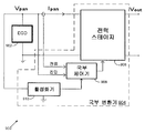
도 9 는 본 출원의 일 실시형태에 따른 에너지 발생 시스템에서 국부 변환기 (904) 에 대한 국부 제어기 (908) 를 활성화 및 비활성화시키는 시스템 (900) 을 도시한다. 이 시스템 (900) 은, 태양 전지 패널 (902) 로 지칭되는 에너지 발생 디바이스 (902) 및 국부 변환기 (904) 를 포함한다. 국부 변환기 (904) 는 전력 스테이지 (906), 국부 제어기 (908) 및 활성화기 (910) 를 포함한다.9 shows a
국부 변환기 (908) 는 도 1 의 국부 변환기들 (104) 중 하나, 도 2 또는 3 의 국부 변환기 (204), 및/또는 도 5 의 국부 변환기들 (504) 중 하나를 나타낼 수도 있지만, 국부 변환기 (904) 는 본 출원의 범주를 벗어나지 않으면서 임의의 적절히 구성된 에너지 발생 시스템으로 구현될 수도 있음을 이해할 것이다. 따라서, 시스템 (900) 은 다른 유사한 시스템 (900) 에 직렬 및/또는 병렬로 커플링되어, 에너지 발생 어레이를 형성할 수도 있다.The
도시된 실시형태에서, 활성화기 (910) 는 패널 (902) 과 국부 제어기 (908) 사이에 커플링된다. 몇몇 실시형태에서, 활성화기 (910) 는 패널 (902) 의 출력 전압에 기초하여 국부 제어기 (908) 를 활성화 및 비활성화시킬 수 있다. 패널 (902) 의 출력 전압이 너무 낮은 경우, 활성화기 (910) 는, 국부 제어기 (908) 에 실질적으로 제로인 공급 전압을 제공하여 그 국부 제어기 (908) 를 셧오프시킬 수도 있다. 패널 (902) 의 출력 전압이 더 높으면, 활성화기 (910) 는, 국부 제어기 (908) 가 동작하도록 국부 제어기 (908) 에 넌-제로 공급 전압을 제공할 수도 있다.In the illustrated embodiment, the
활성화기 (910) 는 국부 제어기 (908) 에 공급 전압을 제공하는 대신에 임의의 적절한 방식으로 국부 제어기 (908) 를 활성화 및 비활성화시킬 수도 있음을 이해할 것이다. 예를 들어, 하나의 대안적 방법으로, 활성화기 (910) 는 국부 제어기 (908) 를 활성화 및 비활성화시키기 위해 국부 제어기 (908) 의 하나 이상의 핀을 설정할 수도 있다. 다른 대안적 방법으로, 활성화기 (910) 는 국부 제어기 (908) 를 활성화하기 위해 국부 제어기 (908) 내의 제 1 레지스터에 제 1 소정값을 기록할 수도 있고, 국부 제어기 (908) 를 비활성화하기 위해 국부 제어기 (908) 내의 제 1 레지스터 또는 제 2 레지스터에 (특정 구현예에 따라 제 1 소정값과 동일할 수도 있고 상이할 수도 있는) 제 2 소정값을 기록할 수도 있다.It will be appreciated that the
따라서, 시스템 (900) 은 배터리 또는 외부 전원을 이용하지 않고 국부 변환기 (904) 의 자동 동작을 제공한다. 태양 광도가 충분히 큰 경우, 출력 패널 전압 Vpan 은, 활성화기 (910) 가 넌-제로 공급 전압 Vcc 를 발생시키는 것을 시작하는 레벨까지 증가한다. 이 때, 국부 제어기 (908) 및/또는 중앙 어레이 제어기 (도 9 에 미도시) 는 레지스터의 초기화, 패널 (902) 들 사이의 예비적 전압 비교, 아날로그-디지털 변환기 교정, 클럭 동기화 또는 인터리빙, 전력 스테이지 (906) 의 동기적 활성화 등과 같은 활성화 과정을 수행하기 시작할 수도 있다. 유사하게, 시스템 (900) 을 비활성화하기 전에, 독립형 애플리케이션의 경우 백업 유닛과의 동기화, 전력 스테이지 (906) 의 동기적 비활성화 등과 같은 비활성화 과정이 수행될 수도 있다. 이 비활성화 과정 동안, 활성화기 (910) 는 활성화되어 유지될 수 있다.Thus,
또한, 몇몇 실시형태에서, 활성화기 (910) 는 국부 변환기 (904) 에 대한 과도 전력 보호를 제공할 수도 있다. 도 3 과 관련하여 전술한 바와 같이, 국부 제어기 (208) 의 일부인 MPPT 제어 블록 (304) 이 과도 전력 보호를 제공할 수도 있다. 그러나, 활성화기 (910) 를 포함하는 시스템에 대한 대안예로서, 활성화기 (910) 는 이 보호를 대신 제공할 수도 있다. 따라서, 이 대안예에서, 출력 전류가 너무 낮게 감소되면, 활성화기 (910) 는, 패널 전압 Vpan 이 출력 전압 Vout 와 대략 동일해지도록 국부 제어기 (908) 의 MPPT 기능을 스위칭 오프할 수도 있다.In some embodiments,
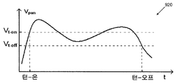
도 10 은 본 출원의 일 실시형태에 따른 시스템 (900) 에 대한 시간에 따른 디바이스 전압 변화의 일예를 도시하는 그래프 (920) 이다. 태양 전지 패널 (902) 에 있어서, 태양 광도 레벨이 활성화기 (910) 에 대한 전압 활성화 레벨 (Vt-on) 주위에서 오실레이팅하는 상황에서, 전압 비활성화 레벨 (Vt-off) 로서 동일한 전압 활성화 레벨을 이용하는 것은 시스템 (900) 의 바람직하지 않은 다수의 활성화 및 비활성화를 발생시킬 것이다. 따라서, 그래프 (920) 에 도시된 바와 같이, 이 시나리오를 방지하기 위해, 더 낮은 전압 비활성화 레벨이 이용될 수도 있다. 이 더 낮은 전압 비활성화 레벨을 이용함으로써, 시스템 (900) 은, 패널 전압이 전압 활성화 레벨보다 다소 낮은 레벨까지 감소하도록 태양 광도 레벨이 충분히 감소할 때까지 계속하여 활성화로 유지될 수도 있다. 그 결과, 빈번한 활성화 및 비활성화가 회피되어 시스템 (900) 에 대한 잡음 내성을 제공한다.10 is a
몇몇 실시형태에서, 패널 전압이 전압 활성화 레벨을 초과하여 국부 제어기 (908) 를 활성화시킨 후, 패널 전압이 전압 비활성화 레벨보다 낮은 레벨까지 계속하여 감소하는 경우 더 신속하게 비활성화하기 위해, 패널 전압이 전압 활성화 레벨 아래로 감소하면 국부 제어기 (908) 는 비활성화 과정을 시작할 수도 있다. 또한, 몇몇 실시형태에서, 국부 제어기 (908) 는, 전압 비활성화 레벨이 특정 상황에 도달하기 전에 활성화기 (910) 를 스스로 셧오프할 수도 있다.In some embodiments, after activating the
도 11 은 본 출원의 일 실시형태에 따른 활성화기 (910) 를 도시한다. 이 실시형태에서, 활성화기 (910) 는 전원 (930), 복수의 저항기 R1, R2 및 R3 및 다이오드 D 를 포함한다. 저항기 R1 및 R2 는 전원 (930) 의 입력 노드 (IN) 와 접지 사이에 직렬로 커플링된다. 다이오드 및 저항기 R3 은 전원 (930) 의 출력 노드 (OUT) 와, 저항기 R1 및 R2 가 서로 커플링된 노드 (940) 사이에 직렬로 커플링된다. 또한, 전원 (930) 의 셧다운 노드 (SD) 가 또한 노드 (940) 에 커플링된다.11 shows an
전원 (930) 은 입력 노드에서 패널 전압 Vpan 을 수신하고, 출력 노드에서 국부 제어기 (908) 에 대한 공급 전압 Vcc 를 발생시킬 수 있다. 전원 (930) 의 셧다운 노드는, 전원 (930) 의 제어 회로에 의해 결정되는 셧다운 노드에서의 전압 레벨이 특정 전압 V0 을 초과하면 전원 (930) 의 동작을 인에이블하고, 셧다운 노드에서의 전압이 그 특정 전압 V0 아래로 감소하면 전원 (930) 의 동작을 디스에이블한다.The
전원 (930) 이 턴오프되는 경우, 다이오드는 도전되지 않고 셧다운 노드에서의 전압은,When

으로 주어진다.Given by
전압 VSD,t-on 이 값 V0 을 초과하는 경우, 다이오드는 도전되기 시작하고, 셧다운 노드에서의 전압은,If the voltage V SD, t-on exceeds the value V 0 , the diode begins to conduct, and the voltage at the shutdown node is

이 되며, 여기서, Vd 는 다이오드 전압 강하이고, ![]()
![]()
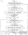
도 12 는 본 출원의 일 실시형태에 따른 국부 변환기 (904) 를 활성화 및 비활성화시키는 방법 (1200) 을 도시한다. 방법 (1200) 의 실시형태는 오직 예시를 위한 것이다. 본 출원의 범주를 벗어나지 않으면서 방법 (1200) 의 다른 실시형태가 구현될 수도 있다.12 illustrates a
방법 (1200) 은 에너지 발생 디바이스 또는 패널 (902) 이 개방 회로 조건에서 동작하는 것에서 시작한다 (단계 1202). 이 조건에서, 패널 (902) 에 의해 출력된 패널 전압이 너무 낮기 때문에, 활성화기 (910) 는 국부 제어기 (908) 를 활성화하지 않는다. 활성화기 (910) 는, 패널 전압 (Vpan) 이 전압 활성화 레벨 (Vt-on) 을 초과할 때까지 이 패널 전압을 모니터링한다 (단계 1024).The
패널 전압이 전압 활성화 레벨을 초과한 것으로 활성화기 (910) 가 결정하면 (단계 1204), 활성화기 (910) 는 국부 제어기 (908) 를 턴온시킴으로써 국부 변환기 (904) 를 활성화하기 시작한다 (단계 1206). 예를 들어, 활성화기 (910) 는 국부 제어기 (908) 에 대한 넌-제로 공급 전압 Vcc 를 발생시킴으로써 국부 변환기 (904) 를 활성화하기 시작한다. 다른 실시형태에서, 활성화기 (910) 는 국부 제어기 (908) 의 하나 이상의 핀을 설정함으로써 또는 국부 제어기 (908) 내의 제 1 레지스터에 제 1 소정값을 기록함으로써 국부 변환기 (904) 를 활성화하기 시작할 수도 있다. 그 후, 국부 제어기 (908) 및/또는 중앙 어레이 제어기는 국부 변환기 (904) 에 대한 활성화 과정을 수행한다 (단계 1208). 예를 들어, 활성화 과정은 레지스터의 초기화, 패널 사이의 예비적 전압 비교 (902), 아날로그-디지털 변환기 교정, 클럭 동기화 또는 인터리빙, 전압 스테이지 (906) 를 포함하는 패널의 스트링의 동기적 활성화 등을 포함할 수도 있다.If the
국부 제어기 (908) 는 스트링의 다른 전압 스테이지 (906) 가 동작할 때까지 (단계 1212) 소정의 변환 비율로 전압 스테이지 (906) 를 동작시킨다 (단계 1210). 스트링 내의 패널 (902) 각각이 동작 전력 스테이지 (906) 를 가지면 (단계 1212), 국부 제어기 (908) 는 패널 전류 (Ipan) 를 활성화 전류 레벨 (Imin) 과 비교한다 (단계 1214). 패널 전류가 활성화 전류 레벨보다 크면 (단계 1214), 국부 제어기 (908) 는 정규로 동작하기 시작한다 (단계 1216). 따라서, 국부 제어기 (908) 는 전력 스테이지 (906) 에 대해 MPPT 를 수행하기 시작한다.The
이 방식으로, 에너지 발생 시스템의 모든 국부 제어기 (908) 의 활성화가 자동으로 동기화될 수도 있다. 또한, 태양 전지 시스템의 패널 (902) 의 오직 서브세트만이 충분히 큰 전압을 생성하여 활성화기 (910) 에 의한 활성화를 발생시키면, 스위치 (314) 와 같은 일방향 스위치가 전력 스테이지 (906) 각각에 포함되어, 나머지 패널 (902) 이 동작되게 할 수도 있다.In this way, activation of all
국부 제어기 (908) 는 패널 전류를 활성화 전류 레벨과 비교하는 것을 계속한다 (단계 1218). 패널 전류가 활성화 전류 레벨보다 작으면 (단계 1218), 국부 제어기 (908) 는 비활성화 타이머를 설정한다 (단계 1220). 그 후, 국부 제어기 (908) 는 전력 스테이지 (906) 를 소정의 변환 비율로 동작시키는 것으로 복귀한다 (단계 1222). 그 후, 국부 제어기 (908) 및/또는 중앙 어레이 제어기는 국부 변환기 (904) 에 대한 비활성화 과정을 수행한다 (단계 1224). 예를 들어, 비활성화 과정은 독립형 애플리케이션의 경우 백업 유닛과의 동기화, 전력 스테이지 (906) 의 동기적 비활성화 등을 포함할 수도 있다.The
그 후, 국부 제어기 (908) 는 비활성화 타이머가 만료되었는지 여부를 결정한다 (단계 1226). 이것은, 패널 전류가 활성화 전류 레벨보다 크게 증가할 시간을 허용한다. 따라서, 국부 제어기 (908) 는 비활성화를 준비하지만, 비활성화가 실제로 수행되어야 하는 것을 보장하기 위해 대기한다.
따라서, 비활성화 타이머가 만료되지 않은 동안 (단계 1226), 국부 제어기 (908) 는 패널 전류를 활성화 전류 레벨과 비교한다 (단계 1228). 패널 전류가 활성화 전류 레벨보다 작게 유지되는 것이 계속되면 (단계 1228), 국부 제어기 (908) 는 비활성화 타이머의 만료를 대기하는 것을 계속한다 (단계 1226). 비활성화 타이머가 만료되기 전에 (단계 1226), 패널 전류가 활성화 전류 레벨보다 크게 되면 (단계 1228), 국부 제어기 (908) 는 전력 스테이지 (906) 에 대해 MPPT 를 수행함으로써 다시 정규로 동작한다 (단계 1216).Thus, while the deactivation timer has not expired (step 1226), the
그러나, 패널 전류가 활성화 전류 레벨보다 작은 동안 (단계 1228) 비활성화 타이머가 만료되지 않으면 (단계 1226), 국부 제어기 (908) 는 전력 스테이지 (906) 및 국부 제어기 (908) 를 턴오프시키고, 패널 (902) 은 개방 회로 조건에서 다시 동작된다 (단계 1230). 몇몇 실시형태에서, 활성화기 (910) 는 국부 제어기 (908) 에 대해 제로 공급 전압 Vcc 를 발생시킴으로써 국부 변환기 (904) 의 비활성화를 완료할 수도 있다. 다른 실시형태에서, 활성화기 (910) 는 국부 제어기 (908) 의 하나 이상의 핀을 설정함으로써, 또는 국부 제어기 (908) 내의 제 1 레지스터 또는 제 2 레지스터에 제 2 소정값을 기록함으로써 국부 변환기 (904) 의 비활성화를 완료할 수도 있다. 이 때, 활성화기 (910) 는, 패널 전압이 전압 활성화 레벨을 초과하여 (단계 1204) 활성화 프로세스를 재시작할 때까지 패널 전압을 다시 한번 모니터링한다.However, if the deactivation timer does not expire (step 1226) while the panel current is less than the activation current level (step 1228), the
도 12 는 국부 변환기 (904) 를 활성화 및 비활성화시키는 방법 (1200) 의 일예를 도시하며, 이 방법 (1200) 에 대한 다양한 변경이 행해질 수도 있다. 예를 들어, 방법 (1200) 은 태양 전지 패널을 참조하여 설명되었지만, 방법 (1200) 은 풍력 터빈, 연료 전지 등과 같은 다른 에너지 발생 디바이스 (902) 에 대해 구현될 수도 있다. 또한, 방법 (1200) 은 도 9 의 국부 제어기 (908) 및 활성화기 (910) 를 참조하여 설명되었지만, 본 출원의 범주를 벗어나지 않으면서 국부 제어기 (908) 및 활성화기 (910) 는 임의의 적절히 구성된 에너지 발생 시스템에 구현될 수도 있음을 이해할 것이다. 또한, 일련의 단계로 도시되었지만, 방법 (1200) 의 단계들은 중첩되거나, 병렬로 발생하거나, 다수회 발생하거나, 상이한 순서로 발생할 수도 있다.12 shows an example of a
전술한 설명은 특정 실시형태들을 언급하지만, 설명된 컴포넌트들, 시스템들 및 방법 중 일부는 서브-셀, 단일 셀, 패널 (즉, 셀 어레이), 패널 어레이 및/또는 패널 어레이의 시스템에 적용될 수도 있음을 이해할 것이다. 예를 들어, 전술한 국부 변환기들은 패널과 각각 연관되지만, 패널의 각각의 셀 또는 패널의 각각의 스트링에 대해 유사한 시스템이 국부 변환기로 구현될 수도 있다. 또한, 전술한 컴포넌트들, 시스템들 및 방법 중 일부는 풍력 터빈, 연료 전지 등과 같은 태양 전지 디바이스 이외의 에너지 발생 디바이스에 적용될 수도 있다.Although the foregoing description refers to specific embodiments, some of the described components, systems, and methods may apply to systems of sub-cells, single cells, panels (ie, cell arrays), panel arrays, and / or panel arrays. I will understand that. For example, the local converters described above are each associated with a panel, but a similar system may be implemented with the local converter for each cell of the panel or each string of the panel. In addition, some of the components, systems, and methods described above may be applied to energy generating devices other than solar cell devices such as wind turbines, fuel cells, and the like.
본 특허 출원에서 사용된 특정 단어 또는 구의 정의를 기술하는 것은 이점이 있을 수도 있다. 용어 "커플링" 및 그 파생어는 2 개 이상의 컴포넌트들이 물리적으로 서로 접촉하고 있는지 여부에 무관하게 그 2 개 이상의 컴포넌트들 사이에서의 임의의 직접 또는 간접 통신을 나타낸다. 용어 "송신", "수신" 및 "통신" 및 그 파생어들은 직접 및 간접 통신 모두를 포함한다. 용어 "포함하다" 및 "구비하다" 및 그 파생어들은 비제한적으로 포함하는 것을 의미한다. 용어 "또는" 은 및/또는 을 의미하는 것을 포함한다. 용어 "각각" 은 식별된 용어의 적어도 서브세트 중 모든 하나를 의미한다. 구 "와 연관된" 및 "그와 연관된" 및 그 파생어들은, 포함하는, 포함되는, 상호작용하는, 함유하는, 함유되는, 접속되는, 커플링되는, 통신하는, 협렵하는, 인터리빙하는, 병치되는, 근접한, 한정된, 갖는, 특성을 갖는 등을 의미할 수도 있다.It may be advantageous to describe the definition of a specific word or phrase used in this patent application. The term "coupling" and its derivatives refer to any direct or indirect communication between the two or more components regardless of whether the two or more components are in physical contact with each other. The terms "send", "receive" and "communication" and their derivatives encompass both direct and indirect communication. The terms "comprise" and "comprise" and their derivatives are meant to include without limitation. The term “or” includes meaning and and / or. The term "each" means every one of at least a subset of the identified terms. The phrases “associated with” and “associated with” and its derivatives include, including, included, interacting with, containing, contained, connected, coupled, communicating, collaborating, interleaving, juxtaposed, and including. , Adjacent, limited, having, characteristics, and the like.
본 출원은 특정 실시형태들 및 및 일반적으로 연관된 방법을 설명하지만, 이 실시형태들 및 방법의 대체예 및 치환예는 당업자에게 자명할 것이다. 따라서, 예시적 실시형태의 전술한 설명은 본 출원을 정의하거나 제한하는 것이 아니다. 다음의 청구항에 의해 정의되는 바와 같이, 본 출원의 사상 및 범주를 벗어나지 않으면서 다른 변경예, 대체예 및 변형예가 또한 가능하다.While the present application describes certain embodiments and generally associated methods, alternatives and substitutions of these embodiments and methods will be apparent to those skilled in the art. Accordingly, the foregoing descriptions of exemplary embodiments do not define or limit the present application. As defined by the following claims, other variations, alternatives, and modifications are also possible without departing from the spirit and scope of the present application.
Claims (23)
상기 방법은 트래킹 모드에서 동작하는 단계를 포함하고,
상기 트래킹 모드에서 동작하는 단계는,
이전의 최적의 변환 비율에 기초하여 상기 버크-부스트 변환기에 대한 변환 비율을 초기화하는 단계;
상기 초기화된 변환 비율과 연관된 디바이스 전력을 계산하는 단계;
상기 변환 비율을 반복적으로 변경하고, 상기 변경된 변환 비율 각각과 연관된 디바이스 전력을 계산하는 단계; 및
상기 계산된 디바이스 전력에 기초하여 상기 버크-부스트 변환기에 대한 현재의 최적의 변환 비율을 식별하는 단계를 포함하고,
상기 현재의 최적의 변환 비율은 상기 버크-부스트 변환기에 대한 버크 모드, 부스트 모드 및 버크-부스트 모드 중 하나에 대응하는, 최대 전력 포인트 트래킹을 제공하는 방법.A method of providing maximum power point tracking to an energy generating device using a local buck-boost converter coupled to an energy generating device, the method comprising:
The method includes operating in a tracking mode,
The operation in the tracking mode,
Initializing a conversion ratio for the buck-boost converter based on a previous optimal conversion ratio;
Calculating device power associated with the initialized conversion ratio;
Iteratively changing the conversion ratio and calculating device power associated with each of the changed conversion ratios; And
Identifying a current optimal conversion ratio for the buck-boost converter based on the calculated device power,
Wherein the current optimal conversion ratio corresponds to one of a buck mode, a boost mode, and a buck-boost mode for the buck-boost converter.
상기 버크-부스트 변환기에 대한 현재의 최적의 변환 비율을 저장하는 단계를 더 포함하는, 최대 전력 포인트 트래킹을 제공하는 방법.The method of claim 1,
Storing a current optimal conversion ratio for the buck-boost converter.
디바이스 전압이 주 임계 전압보다 작은 경우, 휴면 모드에서 동작하는 단계를 더 포함하는, 최대 전력 포인트 트래킹을 제공하는 방법.The method of claim 1,
If the device voltage is less than the main threshold voltage, further comprising operating in a sleep mode.
상기 디바이스 전압이 상기 주 임계 전압을 초과하는 경우 상기 휴면 모드로부터 상기 트래킹 모드로 스위칭하는 단계를 더 포함하는, 최대 전력 포인트 트래킹을 제공하는 방법.The method of claim 3, wherein
Switching from the sleep mode to the tracking mode when the device voltage exceeds the main threshold voltage.
상기 디바이스 전압이, 상기 주 임계 전압보다 작은 보조 임계 전압 아래로 감소하는 경우, 상기 트래킹 모드로부터 상기 휴면 모드로 복귀하는 단계를 더 포함하는, 최대 전력 포인트 트래킹을 제공하는 방법.The method of claim 4, wherein
Returning from the tracking mode to the sleep mode when the device voltage decreases below an auxiliary threshold voltage that is less than the primary threshold voltage.
상기 버크-부스트 변환기에 대한 상기 현재의 최적의 변환 비율이 식별되는 경우,
특정 시간 주기 동안 상기 트래킹 모드로부터 홀딩 모드로 스위칭하는 단계; 및
상기 특정 시간 주기가 경과된 후 상기 홀딩 모드로부터 상기 트래킹 모드로 복귀하는 단계를 더 포함하는, 최대 전력 포인트 트래킹을 제공하는 방법.The method of claim 1,
If the current optimal conversion ratio for the buck-boost converter is identified,
Switching from said tracking mode to a holding mode for a particular period of time; And
Returning from the holding mode to the tracking mode after the specific time period has elapsed.
상기 버크-부스트 변환기에 대한 상기 현재의 최적의 변환 비율이 식별되는 경우,
상기 현재의 최적의 변환 비율이 상기 버크-부스트 변환기에 대한 버크-부스트 모드에 대응하는지 여부를 결정하는 단계;
상기 현재의 최적의 변환 비율이 상기 버크-부스트 모드에 대응하는 경우, 제 1 특정 시간 주기 동안 상기 트래킹 모드로부터 우회 모드로 스위칭하고, 상기 제 1 특정 시간 주기가 경과한 후, 상기 우회 모드로부터 상기 트래킹 모드로 복귀하는 단계; 및
상기 현재의 최적의 변환 비율이 상기 버크-부스트 모드에 대응하지 않는 경우, 제 2 특정 시간 주기 동안 상기 트래킹 모드로부터 홀딩 모드로 스위칭하고, 상기 제 2 특정 시간 주기가 경과한 후, 상기 홀딩 모드로부터 상기 트래킹 모드로 복귀하는 단계를 더 포함하는, 최대 전력 포인트 트래킹을 제공하는 방법.The method of claim 1,
If the current optimal conversion ratio for the buck-boost converter is identified,
Determining whether the current optimal conversion ratio corresponds to a buck-boost mode for the buck-boost converter;
If the current optimal conversion ratio corresponds to the buck-boost mode, switch from the tracking mode to the bypass mode for a first specific time period, and after the first specific time period has elapsed, from the bypass mode Returning to the tracking mode; And
If the current optimal conversion ratio does not correspond to the buck-boost mode, switch from the tracking mode to the holding mode for a second specific time period, and after the second specific time period has elapsed, from the holding mode Returning to the tracking mode further comprising providing maximum power point tracking.
상기 에너지 발생 디바이스는 태양 전지 패널을 포함하는, 최대 전력 포인트 트래킹을 제공하는 방법.The method of claim 1,
And the energy generating device comprises a solar panel.
상기 에너지 발생 디바이스 각각에 대해,
상기 에너지 발생 디바이스로부터 디바이스 전압 및 디바이스 전류를 수신할 수 있고, 상기 디바이스 전압 및 상기 디바이스 전류에 기초하여 출력 전압 및 출력 전류를 발생시킬 수 있는 전력 스테이지; 및
상기 전력 스테이지에 커플링된 국부 변환기를 포함하고,
상기 국부 변환기는,
(i) 이전의 최적의 변환 비율에 기초하여 상기 전력 스테이지에 대한 변환 비율을 초기화하고, (ii) 상기 초기화된 변환 비율과 연관된 디바이스 전력을 계산하고, (iii) 상기 변환 비율을 반복적으로 변경하고, 상기 변경된 변환 비율 각각과 연관된 디바이스 전력을 계산하고, (iv) 상기 계산된 디바이스 전력에 기초하여 상기 전력 스테이지에 대한 현재의 최적의 변환 비율을 식별함으로써, 트래킹 모드에서 동작할 수 있는 MPPT 모듈, 및
상기 MPPT 모듈에 커플링되고, 상기 디바이스 전압, 디바이스 전류, 출력 전압 및 출력 전류를 상기 에너지 발생 어레이에 대한 중앙 어레이 제어기에 제공할 수 있는 통신 인터페이스를 포함하는, 최대 전력 포인트 트래킹을 제공하는 시스템.A system for providing maximum power point tracking (MPPT) to each of a plurality of energy generating devices in an energy generating array,
For each of the energy generating devices,
A power stage capable of receiving a device voltage and a device current from the energy generating device and capable of generating an output voltage and an output current based on the device voltage and the device current; And
A local converter coupled to the power stage,
The local converter,
(i) initialize a conversion ratio for the power stage based on a previous optimal conversion ratio, (ii) calculate device power associated with the initialized conversion ratio, (iii) iteratively change the conversion ratio and An MPPT module operable in a tracking mode by calculating device power associated with each of the changed conversion ratios, and (iv) identifying a current optimal conversion ratio for the power stage based on the calculated device powers; And
A communication interface coupled to the MPPT module, the communication interface capable of providing the device voltage, device current, output voltage and output current to a central array controller for the energy generating array.
상기 MPPT 모듈은 또한 상기 전력 스테이지에 대한 상기 현재의 최적의 변환 비율을 저장할 수 있는, 최대 전력 포인트 트래킹을 제공하는 시스템.The method of claim 9,
The MPPT module can also store the current optimal conversion ratio for the power stage, providing maximum power point tracking.
상기 MPPT 모듈은 또한, 상기 디바이스 전압이 주 임계 전압보다 작은 경우 휴면 모드에서 동작할 수 있고, 상기 디바이스 전압이 상기 주 임계 전압을 초과하는 경우 상기 휴면 모드로부터 상기 트래킹 모드로 스위칭할 수 있는, 최대 전력 포인트 트래킹을 제공하는 시스템.The method of claim 9,
The MPPT module may also operate in sleep mode when the device voltage is less than a main threshold voltage, and switch from the sleep mode to the tracking mode when the device voltage exceeds the main threshold voltage. A system that provides power point tracking.
상기 MPPT 모듈은 또한, 상기 디바이스 전압이, 상기 주 임계 전압보다 작은 보조 임계 전압 아래로 감소하는 경우, 상기 트래킹 모드로부터 상기 휴면 모드로 복귀할 수 있는, 최대 전력 포인트 트래킹을 제공하는 시스템.The method of claim 11,
The MPPT module is also capable of returning from the tracking mode to the sleep mode when the device voltage decreases below an auxiliary threshold voltage less than the main threshold voltage.
상기 MPPT 모듈은 또한, 상기 전력 스테이지에 대한 상기 현재의 최적의 변환 비율이 식별되는 경우,
특정 시간 주기 동안 상기 트래킹 모드로부터 홀딩 모드로 스위칭할 수 있고;
상기 특정 시간 주기가 경과한 후, 상기 홀딩 모드로부터 상기 트래킹 모드로 복귀할 수 있는, 최대 전력 포인트 트래킹을 제공하는 시스템.The method of claim 9,
The MPPT module may also determine that the current optimal conversion ratio for the power stage is identified,
Switch from the tracking mode to the holding mode for a certain period of time;
And return to the tracking mode from the holding mode after the specific time period has elapsed.
상기 현재의 최적의 변환 비율은, 상기 전력 스테이지에 대한 버크 모드, 부스트 모드 및 버크-부스트 모드 중 하나에 대응하고,
상기 MPPT 모듈은 또한, 상기 전력 스테이지에 대한 상기 현재의 최적의 변환 비율이 식별되는 경우,
상기 현재의 최적의 변환 비율이 상기 전력 스테이지에 대한 버크-부스트 모드에 대응하는지 여부를 결정할 수 있고;
상기 현재의 최적의 변환 비율이 상기 버크-부스트 모드에 대응하는 경우, 제 1 특정 시간 주기 동안 상기 트래킹 모드로부터 우회 모드로 스위칭하고, 상기 제 1 특정 시간 주기가 경과한 후, 상기 우회 모드로부터 상기 트래킹 모드로 복귀할 수 있고;
상기 현재의 최적의 변환 비율이 상기 버크-부스트 모드에 대응하지 않는 경우, 제 2 특정 시간 주기 동안 상기 트래킹 모드로부터 홀딩 모드로 스위칭하고, 상기 제 2 특정 시간 주기가 경과한 후, 상기 홀딩 모드로부터 상기 트래킹 모드로 복귀할 수 있는, 최대 전력 포인트 트래킹을 제공하는 시스템.The method of claim 9,
The current optimal conversion ratio corresponds to one of a buck mode, a boost mode and a buck-boost mode for the power stage,
The MPPT module may also determine that the current optimal conversion ratio for the power stage is identified,
Determine whether the current optimal conversion ratio corresponds to a buck-boost mode for the power stage;
If the current optimal conversion ratio corresponds to the buck-boost mode, switch from the tracking mode to the bypass mode for a first specific time period, and after the first specific time period has elapsed, from the bypass mode Can return to the tracking mode;
If the current optimal conversion ratio does not correspond to the buck-boost mode, switch from the tracking mode to the holding mode for a second specific time period, and after the second specific time period has elapsed, from the holding mode A system for providing maximum power point tracking that can return to the tracking mode.
상기 에너지 발생 디바이스들은 태양 전지 패널들을 포함하는, 최대 전력 포인트 트래킹을 제공하는 시스템.The method of claim 9,
The energy generating devices include solar panel panels for providing maximum power point tracking.
상기 에너지 발생 디바이스 각각에 대해,
상기 에너지 발생 디바이스로부터 디바이스 전압 및 디바이스 전류를 수신할 수 있고, 상기 디바이스 전압 및 상기 디바이스 전류에 기초하여 출력 전압 및 출력 전류를 발생시킬 수 있는 단일-인덕터 4-스위치 동기화 버크-부스트 스위칭 조정기; 및
상기 스위칭 조정기에 커플링되고, 상기 디바이스 전압 및 상기 디바이스 전류를 수신할 수 있는 MPPT 모듈을 포함하며,
상기 MPPT 모듈은,
상기 디바이스 전압 및 상기 디바이스 전류에 기초하여 변환 비율을 발생시킬 수 있는 MPPT 제어 블록, 및
상기 MPPT 제어 블록에 커플링되고, 상기 변환 비율에 기초하여 상기 스위칭 조정기에 대한 모드를 선택할 수 있고, 상기 스위칭 조정기를 상기 선택된 모드에서 동작시킬 수 있는 전력 스테이지 조정기를 포함하는, 최대 전력 포인트 트래킹을 제공하는 시스템.A system for providing maximum power point tracking (MPPT) to each of a plurality of energy generating devices in an energy generating array,
For each of the energy generating devices,
A single-inductor four-switch synchronous buck-boost switching regulator capable of receiving device voltage and device current from the energy generating device and capable of generating an output voltage and an output current based on the device voltage and the device current; And
An MPPT module coupled to the switching regulator and capable of receiving the device voltage and the device current,
The MPPT module,
An MPPT control block capable of generating a conversion ratio based on the device voltage and the device current, and
A maximum power point tracking coupled to the MPPT control block and including a power stage regulator capable of selecting a mode for the switching regulator based on the conversion ratio and enabling the switching regulator to operate in the selected mode. Providing system.
상기 전력 스테이지 조정기는 버크-부스트 모드 제어 로직 및 디지털 펄스 폭 변조기를 포함하고, 상기 MPPT 모듈은, 상기 MPPT 제어 블록에 커플링되고, 상기 디바이스 전압을 아날로그 디바이스 전압으로부터 디지털 디바이스 전압으로 변환하고, 상기 디바이스 전류를 아날로그 디바이스 전류로부터 디지털 디바이스 전류로 변환할 수 있는 제 1 아날로그-디지털 변환기 (ADC) 를 더 포함하고, 상기 MPPT 제어 블록은 상기 디지털 디바이스 전압 및 상기 디지털 디바이스 전류에 기초하여 상기 변환 비율을 발생시킬 수 있고, 상기 전력 스테이지 조정기는 상기 변환 비율에 기초하여 상기 스위칭 조정기에 대한 펄스 폭 변조 신호를 발생시킴으로써 상기 스위칭 조정기를 상기 선택된 모드에서 동작시킬 수 있는, 최대 전력 포인트 트래킹을 제공하는 시스템.17. The method of claim 16,
The power stage regulator includes a buck-boost mode control logic and a digital pulse width modulator, the MPPT module is coupled to the MPPT control block, converts the device voltage from an analog device voltage to a digital device voltage, and And a first analog-to-digital converter (ADC) capable of converting device current from analog device current to digital device current, wherein the MPPT control block adjusts the conversion ratio based on the digital device voltage and the digital device current. And the power stage regulator can operate the switching regulator in the selected mode by generating a pulse width modulated signal for the switching regulator based on the conversion ratio.
상기 MPPT 모듈은, 상기 출력 전압을 아날로그 출력 전압으로부터 디지털 출력 전압으로 변환하고, 상기 출력 전류를 아날로그 출력 전류로부터 디지털 출력 전류로 변환할 수 있는 제 2 ADC 를 더 포함하고, 상기 시스템은, 상기 MPPT 모듈에 커플링되고, 상기 디지털 디바이스 전압, 상기 디지털 디바이스 전류, 상기 디지털 출력 전압 및 상기 디지털 출력 전류를 상기 에너지 발생 어레이에 대한 중앙 어레이 제어기에 제공할 수 있는 통신 인터페이스를 더 포함하는, 최대 전력 포인트 트래킹을 제공하는 시스템.The method of claim 17,
The MPPT module further includes a second ADC capable of converting the output voltage from an analog output voltage to a digital output voltage and converting the output current from an analog output current to a digital output current, wherein the system includes the MPPT And a communication interface coupled to the module, the communication interface capable of providing the digital device voltage, the digital device current, the digital output voltage and the digital output current to a central array controller for the energy generating array. A system that provides tracking.
상기 스위칭 조정기는 제 1 트랜지스터, 제 2 트랜지스터, 제 3 트랜지스터, 제 4 트랜지스터, 인덕터 및 커패시터를 포함하고, 상기 제 1 트랜지스터 및 상기 제 2 트랜지스터는 직렬로 커플링되고, 상기 제 3 트랜지스터 및 상기 제 4 트랜지스터는 직렬로 커플링되고, 상기 인덕터는 상기 제 1 트랜지스터와 상기 제 2 트랜지스터 사이의 제 1 노드, 및 상기 제 3 트랜지스터와 상기 제 4 트랜지스터 사이의 제 2 노드에 커플링되고, 상기 커패시터는 상기 제 3 트랜지스터 및 상기 제 4 트랜지스터와 병렬로 커플링되는, 최대 전력 포인트 트래킹을 제공하는 시스템.17. The method of claim 16,
The switching regulator includes a first transistor, a second transistor, a third transistor, a fourth transistor, an inductor, and a capacitor, wherein the first transistor and the second transistor are coupled in series, the third transistor and the third transistor. Four transistors are coupled in series, the inductor is coupled to a first node between the first transistor and the second transistor, and a second node between the third transistor and the fourth transistor, and the capacitor A maximum power point tracking coupled in parallel with the third transistor and the fourth transistor.
상기 전력 스테이지 조정기는, (i) 상기 변환 비율에 기초하여 상기 제 3 트랜지스터를 턴오프시키고, 상기 제 4 트랜지스터를 턴온시키고, 상기 제 1 트랜지스터 및 상기 제 2 트랜지스터를 교대로 턴온시킴으로써 상기 스위칭 조정기를 버크 구성에서 동작시킬 수 있고, (ii) 상기 변환 비율에 기초하여 상기 제 1 트랜지스터를 턴온시키고, 상기 제 2 트랜지스터를 턴오프시키고, 상기 제 3 트랜지스터 및 상기 제 4 트랜지스터를 교대로 턴온시킴으로써 상기 스위칭 조정기를 부스트 구성에서 동작시킬 수 있고, (iii) 상기 변환 비율에 기초하여 상기 버크 구성과 상기 부스트 구성 사이에서 시분할 멀티플렉싱을 수행함으로써 상기 스위칭 조정기를 상기 버크 구성과 상기 부스트 구성에서 교대로 동작시킬 수 있는, 최대 전력 포인트 트래킹을 제공하는 시스템.The method of claim 19,
The power stage regulator may be configured to (i) turn off the third transistor based on the conversion ratio, turn on the fourth transistor, and alternately turn on the first transistor and the second transistor. Operating in a buck configuration, and (ii) the switching by turning on the first transistor based on the conversion ratio, turning off the second transistor, and alternately turning on the third transistor and the fourth transistor. The regulator can be operated in a boost configuration, and (iii) alternately operate the switching regulator in the buck configuration and the boost configuration by performing time division multiplexing between the buck configuration and the boost configuration based on the conversion ratio. System provides maximum power point tracking Tem.
상기 전력 스테이지 조정기는 또한, (i) 상기 제 1 트랜지스터, 상기 제 2 트랜지스터, 상기 제 3 트랜지스터 및 상기 제 4 트랜지스터를 턴오프시킴으로써 상기 스위칭 조정기를 셧다운 모드에서 동작시킬 수 있고, (ii) 상기 제 1 트랜지스터 및 상기 제 4 트랜지스터를 턴온시키고 상기 제 2 트랜지스터 및 상기 제 3 트랜지스터를 턴오프시킴으로써 상기 스위칭 조정기를 우회 모드에서 동작시킬 수 있는, 최대 전력 포인트 트래킹을 제공하는 시스템.The method of claim 20,
The power stage regulator may also operate the switching regulator in a shutdown mode by (i) turning off the first transistor, the second transistor, the third transistor, and the fourth transistor, and (ii) the second Wherein the switching regulator can be operated in bypass mode by turning on a first transistor and the fourth transistor and by turning off the second transistor and the third transistor.
상기 MPPT 제어 블록은 트래킹 모드에서 동작함으로써 상기 변환 비율을 발생시킬 수 있고, 상기 트래킹 모드에서 동작하는 것은, (i) 이전의 최적의 변환 비율에 기초하여 상기 스위칭 조정기에 대한 변환 비율을 초기화하는 것, (ii) 상기 초기화된 변환 비율과 연관된 디바이스 전력을 계산하는 것, (iii) 상기 변환 비율을 반복적으로 변경하고, 상기 변경된 변환 비율 각각과 연관된 디바이스 전력을 계산하는 것, 및 (iv) 상기 계산된 디바이스 전력에 기초하여 상기 스위칭 조정기에 대한 현재의 최적의 변환 비율을 식별하는 것을 포함하고, 상기 현재의 최적의 변환 비율은 상기 MPPT 제어 블록에 의해 발생된 변환 비율을 포함하는, 최대 전력 포인트 트래킹을 제공하는 시스템.17. The method of claim 16,
The MPPT control block may generate the conversion ratio by operating in a tracking mode, wherein operating in the tracking mode comprises (i) initiating a conversion ratio for the switching regulator based on a previous optimal conversion ratio. (ii) calculating device power associated with the initialized conversion rate, (iii) repeatedly changing the conversion rate, calculating device power associated with each of the changed conversion rates, and (iv) calculating Identifying a current optimal conversion ratio for the switching regulator based on the device powers that have been included, wherein the current optimal conversion ratio includes a conversion ratio generated by the MPPT control block. System to provide.
상기 에너지 발생 디바이스들은 태양 전지 패널들을 포함하는, 최대 전력 포인트 트래킹을 제공하는 시스템.17. The method of claim 16,
The energy generating devices include solar panel panels for providing maximum power point tracking.
Applications Claiming Priority (2)
| Application Number | Priority Date | Filing Date | Title |
|---|---|---|---|
| US12/152,491 US7969133B2 (en) | 2008-05-14 | 2008-05-14 | Method and system for providing local converters to provide maximum power point tracking in an energy generating system |
| US12/152,491 | 2008-05-14 |
Publications (1)
| Publication Number | Publication Date |
|---|---|
| KR20110009233A true KR20110009233A (en) | 2011-01-27 |
Family
ID=41315572
Family Applications (1)
| Application Number | Title | Priority Date | Filing Date |
|---|---|---|---|
| KR1020107028021A KR20110009233A (en) | 2008-05-14 | 2009-05-14 | Method and system for providing local converters to provide maximum power point tracking in an energy generating system |
Country Status (7)
| Country | Link |
|---|---|
| US (1) | US7969133B2 (en) |
| EP (1) | EP2291907A4 (en) |
| JP (1) | JP5361994B2 (en) |
| KR (1) | KR20110009233A (en) |
| CN (1) | CN102089961A (en) |
| TW (1) | TW201013359A (en) |
| WO (1) | WO2009140539A2 (en) |
Cited By (5)
| Publication number | Priority date | Publication date | Assignee | Title |
|---|---|---|---|---|
| KR101141074B1 (en) * | 2012-02-02 | 2012-05-03 | 주식회사 케이디파워 | Photovoltaic power generation system include multi-inverter |
| KR101425935B1 (en) * | 2011-10-17 | 2014-08-05 | 주식회사 케이디파워 | Photovoltaic power generation apparatus |
| KR101504904B1 (en) * | 2013-10-01 | 2015-03-23 | 주식회사 동아일렉콤 | High efficient wireless energy transfer |
| KR102034431B1 (en) * | 2018-05-11 | 2019-10-18 | 청주대학교 산학협력단 | Maximum Power Generation System of Solar Panel |
| WO2022145907A1 (en) * | 2020-12-31 | 2022-07-07 | 주식회사 스마트파워 | String optima for tracking equal voltage in units of strings, and solar power generation system to which same is applied |
Families Citing this family (165)
| Publication number | Priority date | Publication date | Assignee | Title |
|---|---|---|---|---|
| US11881814B2 (en) | 2005-12-05 | 2024-01-23 | Solaredge Technologies Ltd. | Testing of a photovoltaic panel |
| US10693415B2 (en) | 2007-12-05 | 2020-06-23 | Solaredge Technologies Ltd. | Testing of a photovoltaic panel |
| US11855231B2 (en) | 2006-12-06 | 2023-12-26 | Solaredge Technologies Ltd. | Distributed power harvesting systems using DC power sources |
| US8963369B2 (en) | 2007-12-04 | 2015-02-24 | Solaredge Technologies Ltd. | Distributed power harvesting systems using DC power sources |
| US11296650B2 (en) | 2006-12-06 | 2022-04-05 | Solaredge Technologies Ltd. | System and method for protection during inverter shutdown in distributed power installations |
| US9112379B2 (en) | 2006-12-06 | 2015-08-18 | Solaredge Technologies Ltd. | Pairing of components in a direct current distributed power generation system |
| US9088178B2 (en) | 2006-12-06 | 2015-07-21 | Solaredge Technologies Ltd | Distributed power harvesting systems using DC power sources |
| US8319483B2 (en) | 2007-08-06 | 2012-11-27 | Solaredge Technologies Ltd. | Digital average input current control in power converter |
| US11888387B2 (en) | 2006-12-06 | 2024-01-30 | Solaredge Technologies Ltd. | Safety mechanisms, wake up and shutdown methods in distributed power installations |
| US8947194B2 (en) | 2009-05-26 | 2015-02-03 | Solaredge Technologies Ltd. | Theft detection and prevention in a power generation system |
| US8319471B2 (en) | 2006-12-06 | 2012-11-27 | Solaredge, Ltd. | Battery power delivery module |
| US11309832B2 (en) | 2006-12-06 | 2022-04-19 | Solaredge Technologies Ltd. | Distributed power harvesting systems using DC power sources |
| US8473250B2 (en) | 2006-12-06 | 2013-06-25 | Solaredge, Ltd. | Monitoring of distributed power harvesting systems using DC power sources |
| US9130401B2 (en) | 2006-12-06 | 2015-09-08 | Solaredge Technologies Ltd. | Distributed power harvesting systems using DC power sources |
| US8618692B2 (en) | 2007-12-04 | 2013-12-31 | Solaredge Technologies Ltd. | Distributed power system using direct current power sources |
| US11569659B2 (en) | 2006-12-06 | 2023-01-31 | Solaredge Technologies Ltd. | Distributed power harvesting systems using DC power sources |
| US11687112B2 (en) | 2006-12-06 | 2023-06-27 | Solaredge Technologies Ltd. | Distributed power harvesting systems using DC power sources |
| US8384243B2 (en) | 2007-12-04 | 2013-02-26 | Solaredge Technologies Ltd. | Distributed power harvesting systems using DC power sources |
| US11728768B2 (en) | 2006-12-06 | 2023-08-15 | Solaredge Technologies Ltd. | Pairing of components in a direct current distributed power generation system |
| US11735910B2 (en) | 2006-12-06 | 2023-08-22 | Solaredge Technologies Ltd. | Distributed power system using direct current power sources |
| US8816535B2 (en) | 2007-10-10 | 2014-08-26 | Solaredge Technologies, Ltd. | System and method for protection during inverter shutdown in distributed power installations |
| US8013472B2 (en) | 2006-12-06 | 2011-09-06 | Solaredge, Ltd. | Method for distributed power harvesting using DC power sources |
| WO2009055474A1 (en) | 2007-10-23 | 2009-04-30 | And, Llc | High reliability power systems and solar power converters |
| EP3324505B1 (en) | 2007-10-15 | 2023-06-07 | Ampt, Llc | Systems for highly efficient solar power |
| US8294451B2 (en) * | 2007-12-03 | 2012-10-23 | Texas Instruments Incorporated | Smart sensors for solar panels |
| US8049523B2 (en) | 2007-12-05 | 2011-11-01 | Solaredge Technologies Ltd. | Current sensing on a MOSFET |
| EP2232690B1 (en) | 2007-12-05 | 2016-08-31 | Solaredge Technologies Ltd. | Parallel connected inverters |
| US11264947B2 (en) | 2007-12-05 | 2022-03-01 | Solaredge Technologies Ltd. | Testing of a photovoltaic panel |
| JP2011507465A (en) * | 2007-12-05 | 2011-03-03 | ソラレッジ テクノロジーズ リミテッド | Safety mechanism, wake-up method and shutdown method in distributed power installation |
| WO2009072075A2 (en) | 2007-12-05 | 2009-06-11 | Solaredge Technologies Ltd. | Photovoltaic system power tracking method |
| EP2269290B1 (en) | 2008-03-24 | 2018-12-19 | Solaredge Technologies Ltd. | Switch mode converter including active clamp for achieving zero voltage switching |
| US8289183B1 (en) | 2008-04-25 | 2012-10-16 | Texas Instruments Incorporated | System and method for solar panel array analysis |
| EP2294669B8 (en) | 2008-05-05 | 2016-12-07 | Solaredge Technologies Ltd. | Direct current power combiner |
| CN102067429A (en) * | 2008-05-14 | 2011-05-18 | 国家半导体公司 | System and method for an array of intelligent inverters |
| US7991511B2 (en) * | 2008-05-14 | 2011-08-02 | National Semiconductor Corporation | Method and system for selecting between centralized and distributed maximum power point tracking in an energy generating system |
| US7962249B1 (en) * | 2008-05-14 | 2011-06-14 | National Semiconductor Corporation | Method and system for providing central control in an energy generating system |
| US7969133B2 (en) | 2008-05-14 | 2011-06-28 | National Semiconductor Corporation | Method and system for providing local converters to provide maximum power point tracking in an energy generating system |
| US8279644B2 (en) * | 2008-05-14 | 2012-10-02 | National Semiconductor Corporation | Method and system for providing maximum power point tracking in an energy generating system |
| US9077206B2 (en) | 2008-05-14 | 2015-07-07 | National Semiconductor Corporation | Method and system for activating and deactivating an energy generating system |
| US8139382B2 (en) * | 2008-05-14 | 2012-03-20 | National Semiconductor Corporation | System and method for integrating local maximum power point tracking into an energy generating system having centralized maximum power point tracking |
| US8325059B2 (en) * | 2008-11-12 | 2012-12-04 | Tigo Energy, Inc. | Method and system for cost-effective power line communications for sensor data collection |
| US8653689B2 (en) * | 2008-11-12 | 2014-02-18 | Tigo Energy, Inc. | Method and system for current-mode power line communications |
| US10153383B2 (en) * | 2008-11-21 | 2018-12-11 | National Semiconductor Corporation | Solar string power point optimization |
| US20100156188A1 (en) * | 2008-12-24 | 2010-06-24 | Fishman Oleg S | Solar Photovoltaic Power Collection via High Voltage, Direct Current Systems with Conversion and Supply to an Alternating Current Transmission Network |
| US8212408B2 (en) * | 2008-12-24 | 2012-07-03 | Alencon Acquisition Co., Llc. | Collection of electric power from renewable energy sources via high voltage, direct current systems with conversion and supply to an alternating current transmission network |
| US9401439B2 (en) * | 2009-03-25 | 2016-07-26 | Tigo Energy, Inc. | Enhanced systems and methods for using a power converter for balancing modules in single-string and multi-string configurations |
| CN102484364B (en) * | 2009-04-17 | 2016-04-13 | 美国国家半导体公司 | By distributed MPPT maximum power point tracking, photovoltaic system is carried out to the system and method for overvoltage protection |
| CN102460878B (en) * | 2009-04-17 | 2015-12-16 | 美国国家半导体公司 | For the system and method for overvoltage protection in photovoltaic system |
| WO2010120315A1 (en) | 2009-04-17 | 2010-10-21 | Ampt, Llc | Methods and apparatus for adaptive operation of solar power systems |
| US20100288327A1 (en) * | 2009-05-13 | 2010-11-18 | National Semiconductor Corporation | System and method for over-Voltage protection of a photovoltaic string with distributed maximum power point tracking |
| US20100301676A1 (en) * | 2009-05-28 | 2010-12-02 | General Electric Company | Solar power generation system including weatherable units including photovoltaic modules and isolated power converters |
| EP2282392A1 (en) * | 2009-07-31 | 2011-02-09 | Nxp B.V. | A battery charger for a photovoltaic system, a controller therefor and a method of controlling the same |
| US20110084646A1 (en) * | 2009-10-14 | 2011-04-14 | National Semiconductor Corporation | Off-grid led street lighting system with multiple panel-storage matching |
| WO2011049985A1 (en) | 2009-10-19 | 2011-04-28 | Ampt, Llc | Novel solar panel string converter topology |
| US8421400B1 (en) | 2009-10-30 | 2013-04-16 | National Semiconductor Corporation | Solar-powered battery charger and related system and method |
| EP2333634A1 (en) * | 2009-12-14 | 2011-06-15 | Mitsubishi Electric R&D Centre Europe B.V. | Method for obtaining information enabling the determination of a characteristic of a power source |
| EP2333635A1 (en) * | 2009-12-14 | 2011-06-15 | Mitsubishi Electric R&D Centre Europe B.V. | Method for obtaining information enabling the determination of a characteristic of a power source |
| US9342088B2 (en) * | 2009-12-31 | 2016-05-17 | Sunpower Corporation | Power point tracking |
| US9819182B1 (en) * | 2010-01-12 | 2017-11-14 | Sunpower Corporation | Systemic optimization of photovoltaic apparatus |
| US8975783B2 (en) * | 2010-01-20 | 2015-03-10 | Draker, Inc. | Dual-loop dynamic fast-tracking MPPT control method, device, and system |
| US8390261B2 (en) * | 2010-05-21 | 2013-03-05 | Infineon Technologies Austria Ag | Maximum power point tracker bypass |
| EP2408097A1 (en) * | 2010-07-12 | 2012-01-18 | ABB Oy | Current-fed converter |
| EP2408096A1 (en) * | 2010-07-12 | 2012-01-18 | ABB Oy | Current-fed converter with quadratic conversion ratio |
| US8552587B2 (en) | 2010-07-20 | 2013-10-08 | Igrenenergi Semiconductor Technologies Pvt. Ltd. | Power conversion for distributed DC source array |
| US9331499B2 (en) | 2010-08-18 | 2016-05-03 | Volterra Semiconductor LLC | System, method, module, and energy exchanger for optimizing output of series-connected photovoltaic and electrochemical devices |
| US9035626B2 (en) | 2010-08-18 | 2015-05-19 | Volterra Semiconductor Corporation | Switching circuits for extracting power from an electric power source and associated methods |
| CN101917131B (en) * | 2010-08-19 | 2012-06-06 | 浙江大学 | Cascade Buck-boost high power factor alternating current-direct current (AC-DC) converter and current converting method |
| US20120049635A1 (en) * | 2010-08-27 | 2012-03-01 | General Electric Company | Solar power generation system and method |
| US8810214B2 (en) * | 2010-09-30 | 2014-08-19 | Nxp B.V. | Multi-mode power supply circuit with a normal operational mode and a pass-through operational mode and a method for operating the multi-mode power supply circuit |
| JP5691365B2 (en) * | 2010-10-07 | 2015-04-01 | ソニー株式会社 | Power control apparatus, power control method, and power supply system |
| GB2484524A (en) | 2010-10-14 | 2012-04-18 | Powervation Ltd | Pin programming a power supply controller |
| TW201217961A (en) * | 2010-10-20 | 2012-05-01 | Hon Hai Prec Ind Co Ltd | Conversion efficiency testing device and using the same |
| US10673222B2 (en) | 2010-11-09 | 2020-06-02 | Solaredge Technologies Ltd. | Arc detection and prevention in a power generation system |
| US10673229B2 (en) | 2010-11-09 | 2020-06-02 | Solaredge Technologies Ltd. | Arc detection and prevention in a power generation system |
| GB2485527B (en) | 2010-11-09 | 2012-12-19 | Solaredge Technologies Ltd | Arc detection and prevention in a power generation system |
| US10230310B2 (en) | 2016-04-05 | 2019-03-12 | Solaredge Technologies Ltd | Safety switch for photovoltaic systems |
| GB2486408A (en) | 2010-12-09 | 2012-06-20 | Solaredge Technologies Ltd | Disconnection of a string carrying direct current |
| CN102570804B (en) * | 2010-12-28 | 2015-02-25 | 台达电子工业股份有限公司 | DC (direct current) power supply conversion module and control method thereof as well as connector and energy collection system |
| GB2483317B (en) | 2011-01-12 | 2012-08-22 | Solaredge Technologies Ltd | Serially connected inverters |
| US8970068B2 (en) | 2011-02-10 | 2015-03-03 | Draker, Inc. | Pseudo-random bit sequence generation for maximum power point tracking in photovoltaic arrays |
| US8686332B2 (en) | 2011-03-07 | 2014-04-01 | National Semiconductor Corporation | Optically-controlled shunt circuit for maximizing photovoltaic panel efficiency |
| US9225199B2 (en) * | 2011-03-22 | 2015-12-29 | Triune Ip, Llc | Variable power energy harvesting system |
| US8193788B2 (en) * | 2011-04-27 | 2012-06-05 | Solarbridge Technologies, Inc. | Method and device for controlling a configurable power supply to provide AC and/or DC power output |
| US9577425B1 (en) * | 2011-05-23 | 2017-02-21 | The Board Of Trustees Of The University Of Alabama | Systems and methods for controlling power switching converters for photovoltaic panels |
| US9252294B2 (en) * | 2011-06-08 | 2016-02-02 | Andrew V. Latham | Instantaneous solar array recombining technology |
| US20130009700A1 (en) * | 2011-07-08 | 2013-01-10 | Infineon Technologies Ag | Power Converter Circuit with AC Output |
| US9431825B2 (en) | 2011-07-28 | 2016-08-30 | Tigo Energy, Inc. | Systems and methods to reduce the number and cost of management units of distributed power generators |
| US9368965B2 (en) | 2011-07-28 | 2016-06-14 | Tigo Energy, Inc. | Enhanced system and method for string-balancing |
| US9142965B2 (en) | 2011-07-28 | 2015-09-22 | Tigo Energy, Inc. | Systems and methods to combine strings of solar panels |
| US9103328B1 (en) | 2011-08-15 | 2015-08-11 | Richard D Kilgore | Magnified solar energy generator |
| US8570005B2 (en) | 2011-09-12 | 2013-10-29 | Solaredge Technologies Ltd. | Direct current link circuit |
| US9837556B2 (en) | 2011-10-31 | 2017-12-05 | Volterra Semiconductor LLC | Integrated photovoltaic panel with sectional maximum power point tracking |
| US8786371B2 (en) | 2011-11-18 | 2014-07-22 | Skyworks Solutions, Inc. | Apparatus and methods for voltage converters |
| TWI438602B (en) | 2011-12-02 | 2014-05-21 | Ind Tech Res Inst | Maximum power point tracking controllers, maximum power point tracking systems and maximum power point tracking methods |
| GB2498365A (en) | 2012-01-11 | 2013-07-17 | Solaredge Technologies Ltd | Photovoltaic module |
| US20150008865A1 (en) * | 2012-01-11 | 2015-01-08 | Koninklijke Philips N.V. | Solar power converter and method of controlling solar power conversion |
| GB2498791A (en) | 2012-01-30 | 2013-07-31 | Solaredge Technologies Ltd | Photovoltaic panel circuitry |
| GB2498790A (en) | 2012-01-30 | 2013-07-31 | Solaredge Technologies Ltd | Maximising power in a photovoltaic distributed power system |
| US9853565B2 (en) * | 2012-01-30 | 2017-12-26 | Solaredge Technologies Ltd. | Maximized power in a photovoltaic distributed power system |
| US9042136B2 (en) * | 2012-02-02 | 2015-05-26 | Engen Technologies Llc | Magnetic flux conversion device |
| GB2499991A (en) | 2012-03-05 | 2013-09-11 | Solaredge Technologies Ltd | DC link circuit for photovoltaic array |
| US9389628B2 (en) * | 2012-04-20 | 2016-07-12 | Intel Deutschland Gmbh | Digitally controlled buck-boost regulator having a custom mapping controller |
| US9348388B2 (en) * | 2012-04-27 | 2016-05-24 | Apple Inc. | Power management systems for accepting adapter and solar power in electronic devices |
| WO2013177360A1 (en) | 2012-05-25 | 2013-11-28 | Solaredge Technologies Ltd. | Circuit for interconnected direct current power sources |
| US10115841B2 (en) | 2012-06-04 | 2018-10-30 | Solaredge Technologies Ltd. | Integrated photovoltaic panel circuitry |
| TWI487239B (en) * | 2012-08-15 | 2015-06-01 | Atomic Energy Council | Household power parallel converter applied to solar power generation system with maximum power tracking effect |
| US9557758B2 (en) | 2012-10-16 | 2017-01-31 | Volterra Semiconductor LLC | Systems and methods for controlling maximum power point tracking controllers |
| US20140103892A1 (en) * | 2012-10-16 | 2014-04-17 | Volterra Semiconductor Corporation | Scalable maximum power point tracking controllers and associated methods |
| DE112012007202B4 (en) * | 2012-10-16 | 2021-12-16 | Volterra Semiconductor Corporation | Systems and methods for controlling regulators for maximum power point tracking |
| US9141123B2 (en) | 2012-10-16 | 2015-09-22 | Volterra Semiconductor LLC | Maximum power point tracking controllers and associated systems and methods |
| WO2014077355A1 (en) * | 2012-11-15 | 2014-05-22 | 太陽誘電株式会社 | Power conversion device |
| US9548619B2 (en) | 2013-03-14 | 2017-01-17 | Solaredge Technologies Ltd. | Method and apparatus for storing and depleting energy |
| US9941813B2 (en) | 2013-03-14 | 2018-04-10 | Solaredge Technologies Ltd. | High frequency multi-level inverter |
| EP3506370B1 (en) | 2013-03-15 | 2023-12-20 | Solaredge Technologies Ltd. | Bypass mechanism |
| US9154095B2 (en) | 2013-03-15 | 2015-10-06 | Bose Corporation | Boost-on-demand amplifier |
| US9184705B2 (en) | 2013-03-15 | 2015-11-10 | Bose Corporation | Feedback mechanism for boost-on-demand amplifiers |
| US9397497B2 (en) | 2013-03-15 | 2016-07-19 | Ampt, Llc | High efficiency interleaved solar power supply system |
| WO2014147771A1 (en) * | 2013-03-20 | 2014-09-25 | 富士電機株式会社 | Solar power generation system |
| US9231476B2 (en) * | 2013-05-01 | 2016-01-05 | Texas Instruments Incorporated | Tracking energy consumption using a boost-buck technique |
| KR101452776B1 (en) | 2013-07-10 | 2014-12-17 | 엘에스산전 주식회사 | Photovoltaic system |
| US9397501B2 (en) | 2013-09-09 | 2016-07-19 | Mitsubishi Electric Research Laboratories, Inc. | Maximum power point tracking for photovoltaic power generation system |
| JP5915619B2 (en) * | 2013-10-22 | 2016-05-11 | トヨタ自動車株式会社 | Photovoltaic power generation device and control method of solar power generation device |
| KR102230134B1 (en) * | 2014-01-03 | 2021-03-19 | 주식회사 솔루엠 | Power factor correction appratus |
| JP6246616B2 (en) * | 2014-02-25 | 2017-12-13 | 太陽誘電株式会社 | Converter and photovoltaic power generation system including the converter |
| EP3112974B1 (en) * | 2014-02-27 | 2019-01-09 | Panasonic Intellectual Property Management Co., Ltd. | Power controller and power conditioner |
| CN103840529B (en) * | 2014-03-19 | 2016-04-13 | 西安科技大学 | The solar charging/discharging control system controlled based on ARM and control method |
| US9318974B2 (en) | 2014-03-26 | 2016-04-19 | Solaredge Technologies Ltd. | Multi-level inverter with flying capacitor topology |
| TWI514714B (en) * | 2014-12-09 | 2015-12-21 | Univ Nat Cheng Kung | Distributed solar power system and controlling method thereof |
| US9496710B2 (en) * | 2014-12-29 | 2016-11-15 | Solarcity Corporation | Rapid shutdown solid state circuit for photovoltaic energy generation systems |
| CA2997792C (en) | 2015-10-02 | 2020-03-24 | Franklin Fueling Systems, Inc. | Solar fueling station |
| JP6508005B2 (en) * | 2015-11-10 | 2019-05-08 | トヨタ自動車株式会社 | Power supply |
| US11018623B2 (en) | 2016-04-05 | 2021-05-25 | Solaredge Technologies Ltd. | Safety switch for photovoltaic systems |
| US11177663B2 (en) | 2016-04-05 | 2021-11-16 | Solaredge Technologies Ltd. | Chain of power devices |
| BE1023318B1 (en) * | 2016-04-29 | 2017-02-03 | Futech Bvba | METHOD AND DEVICE FOR CHARGING AN ENERGY STORAGE SYSTEM IN A SOLAR PANEL INSTALLATION |
| TWI626522B (en) | 2016-08-15 | 2018-06-11 | 財團法人工業技術研究院 | Power point tracking method and apparatus thereof |
| CN106787114B (en) * | 2017-01-20 | 2024-01-16 | 国家电网公司 | Embedded wearable solar power supply system and control method thereof |
| CN107733230B (en) * | 2017-11-21 | 2019-11-05 | 西安特锐德智能充电科技有限公司 | A kind of BuckBoost circuit and its control method |
| CN107947321A (en) * | 2017-12-05 | 2018-04-20 | 上海电机学院 | A kind of solar energy hybrid-driven miniature electric automobile with string type MPPT |
| CN112166547B (en) * | 2018-01-05 | 2021-11-16 | 阿特拉佐有限公司 | Power management system |
| US10614184B2 (en) | 2018-01-08 | 2020-04-07 | Atlazo, Inc. | Semiconductor process and performance sensor |
| US10416746B2 (en) | 2018-01-10 | 2019-09-17 | Atlazo, Inc. | Adaptive energy optimal computing |
| US10635130B2 (en) | 2018-02-01 | 2020-04-28 | Atlazo, Inc. | Process, voltage and temperature tolerant clock generator |
| US10571945B2 (en) | 2018-02-21 | 2020-02-25 | Atlazo, Inc. | Low power regulator circuits, systems and methods regarding the same |
| US10700604B2 (en) | 2018-03-07 | 2020-06-30 | Atlazo, Inc. | High performance switch devices and methods for operating the same |
| TWI677182B (en) * | 2018-05-30 | 2019-11-11 | 俊麟 郭 | Optimized input and output power control solar power supply device and equipment |
| US11381185B2 (en) | 2018-06-08 | 2022-07-05 | Kabushiki Kaishatoshiba | Power control circuit and power generation system including the same |
| DK201870542A1 (en) | 2018-08-21 | 2020-03-24 | Vestas Wind Systems A/S | Method of operating a hybrid power plant to optimise pv power output |
| US11081961B2 (en) * | 2018-11-06 | 2021-08-03 | Taiyo Yudenco., Ltd. | Power convertor, power generation system, and power generation control method |
| IL263278B1 (en) * | 2018-11-25 | 2024-03-01 | Vigdu V Tech Ltd | A dc pullup system for optimizing solar string power generation systems |
| IL263277B (en) * | 2018-11-25 | 2021-12-01 | Vigdu V Tech Ltd | A matcher for multi module solar string power generation systems and a method thereof |
| CN109765960B (en) * | 2019-03-04 | 2020-08-28 | 上海数明半导体有限公司 | Maximum power tracking power generation device and system |
| CN113767569A (en) * | 2019-05-03 | 2021-12-07 | 耐克斯特拉克尔有限公司 | System and method for photovoltaic Direct Current (DC) bus control |
| US10742242B1 (en) * | 2019-06-05 | 2020-08-11 | Silicon Laboratories Inc. | Apparatus for improving the effective performance of a power source and associated methods |
| CN110391676B (en) * | 2019-08-09 | 2021-07-20 | 阳光电源股份有限公司 | Multi-path MPPT inverter and control method thereof |
| EP3800758B1 (en) * | 2019-10-02 | 2022-07-20 | VKR Holding A/S | System with sleep function for powering a power consumption device of building equipment |
| SE2050663A1 (en) * | 2020-06-05 | 2021-07-27 | Myfc Ab | A fuel cell and battery hybrid system |
| US10992149B1 (en) | 2020-10-08 | 2021-04-27 | Element Energy, Inc. | Safe battery energy management systems, battery management system nodes, and methods |
| US11791642B2 (en) | 2020-10-08 | 2023-10-17 | Element Energy, Inc. | Safe battery energy management systems, battery management system nodes, and methods |
| US11831192B2 (en) | 2021-07-07 | 2023-11-28 | Element Energy, Inc. | Battery management controllers and associated methods |
| US11269012B1 (en) | 2021-07-19 | 2022-03-08 | Element Energy, Inc. | Battery modules for determining temperature and voltage characteristics of electrochemical cells, and associated methods |
| US11370308B1 (en) | 2021-09-03 | 2022-06-28 | IRP Nexus Group, Ltd. | Parallel power distribution and charging system |
| CN113760036B (en) * | 2021-09-26 | 2023-05-12 | 中机国能电力工程有限公司 | Component optical power tracking circuit |
| US11699909B1 (en) | 2022-02-09 | 2023-07-11 | Element Energy, Inc. | Controllers for managing a plurality of stacks of electrochemical cells, and associated methods |
| US11644886B1 (en) | 2022-05-17 | 2023-05-09 | IRP Nexus Group, Ltd. | Dual power units based power distribution system |
| US11664670B1 (en) | 2022-08-21 | 2023-05-30 | Element Energy, Inc. | Methods and systems for updating state of charge estimates of individual cells in battery packs |
Family Cites Families (79)
| Publication number | Priority date | Publication date | Assignee | Title |
|---|---|---|---|---|
| US3740636A (en) * | 1971-11-05 | 1973-06-19 | Us Navy | Charge regulator and monitor for spacecraft solar cell/battery system control |
| US4129788A (en) * | 1977-04-26 | 1978-12-12 | Dracon Industries | High efficiency DC to DC converter |
| JPS6154820A (en) * | 1984-08-23 | 1986-03-19 | シャープ株式会社 | Dc/ac converter of photogenerator system |
| US4688538A (en) * | 1984-12-31 | 1987-08-25 | Combustion Electromagnetics, Inc. | Rapid pulsed multiple pulse ignition and high efficiency power inverter with controlled output characteristics |
| DE4032569A1 (en) * | 1990-10-13 | 1992-04-16 | Flachglas Solartechnik Gmbh | Photovoltaic system coupled to mains network - has individual modules incorporating respective DC-AC converter for direct supply of mains network |
| US5408404A (en) * | 1993-03-25 | 1995-04-18 | Rockwell International Corp. | High frequency interleaved DC-to-AC power converter apparatus |
| JPH07234733A (en) | 1994-02-22 | 1995-09-05 | Sanyo Electric Co Ltd | Maximum power point tracking method |
| JPH08123563A (en) | 1994-10-28 | 1996-05-17 | Canon Inc | Photovoltaic power generation system, device and method for controlling power for the same |
| JP3567944B2 (en) | 1995-05-16 | 2004-09-22 | 株式会社安川電機 | Power converter for photovoltaic power generation |
| US5751120A (en) * | 1995-08-18 | 1998-05-12 | Siemens Stromberg-Carlson | DC operated electronic ballast for fluorescent light |
| JP3382434B2 (en) * | 1995-09-22 | 2003-03-04 | キヤノン株式会社 | Battery power supply voltage control device and voltage control method |
| US5747967A (en) * | 1996-02-22 | 1998-05-05 | Midwest Research Institute | Apparatus and method for maximizing power delivered by a photovoltaic array |
| JPH1014105A (en) | 1996-06-27 | 1998-01-16 | Ohbayashi Corp | Supply of photovoltaic power to electric equipment |
| JP3554116B2 (en) * | 1996-09-06 | 2004-08-18 | キヤノン株式会社 | Power control device and solar power generation system using the same |
| JP3144323B2 (en) | 1996-11-21 | 2001-03-12 | 日新電機株式会社 | Solar power generator |
| JPH1198679A (en) | 1997-09-18 | 1999-04-09 | Mitsubishi Electric Corp | Converter device |
| US6111767A (en) * | 1998-06-22 | 2000-08-29 | Heliotronics, Inc. | Inverter integrated instrumentation having a current-voltage curve tracer |
| JP2000116010A (en) | 1998-09-30 | 2000-04-21 | Nissin Electric Co Ltd | Distributed power supply system |
| JP2000112545A (en) | 1998-09-30 | 2000-04-21 | Daihen Corp | Photovoltaic power generation system |
| JP2000228529A (en) * | 1998-11-30 | 2000-08-15 | Canon Inc | Solar cell module having overvoltage preventing element and solar light power generating system using the same |
| US6198178B1 (en) * | 1999-12-21 | 2001-03-06 | International Power Systems, Inc. | Step wave power converter |
| JP3809316B2 (en) * | 1999-01-28 | 2006-08-16 | キヤノン株式会社 | Solar power plant |
| US6633823B2 (en) * | 2000-07-13 | 2003-10-14 | Nxegen, Inc. | System and method for monitoring and controlling energy usage |
| US6281485B1 (en) * | 2000-09-27 | 2001-08-28 | The Aerospace Corporation | Maximum power tracking solar power system |
| JP4651832B2 (en) | 2001-03-05 | 2011-03-16 | 富士通セミコンダクター株式会社 | Overvoltage protection device for power system |
| JP3394996B2 (en) * | 2001-03-09 | 2003-04-07 | 独立行政法人産業技術総合研究所 | Maximum power operating point tracking method and device |
| JP2002324566A (en) * | 2001-04-25 | 2002-11-08 | Sanyo Electric Co Ltd | Distributed power-generating system, and maintenance system and method utilizing it |
| US7925210B2 (en) * | 2001-05-21 | 2011-04-12 | Sirf Technology, Inc. | Synchronizing a radio network with end user radio terminals |
| JP2003134661A (en) | 2001-10-17 | 2003-05-09 | Mitsubishi Heavy Ind Ltd | Load interruption detecting device and photovoltaic power generator |
| AU2002348084A1 (en) * | 2001-10-25 | 2003-05-06 | Sandia Corporation | Alternating current photovoltaic building block |
| JP2003216255A (en) | 2002-01-18 | 2003-07-31 | Matsushita Electric Ind Co Ltd | Method for controlling converter in solar power generation device |
| DE10222621A1 (en) * | 2002-05-17 | 2003-11-27 | Josef Steger | Process and circuit to control and regulated a photovoltaic device assembly for solar energy has controlled bypass for each cell to ensure maximum power operation |
| JP4267274B2 (en) * | 2002-08-28 | 2009-05-27 | 富士通マイクロエレクトロニクス株式会社 | Power supply fluctuation suppressing device, semiconductor device, and power supply fluctuation suppressing method |
| US6966184B2 (en) * | 2002-11-25 | 2005-11-22 | Canon Kabushiki Kaisha | Photovoltaic power generating apparatus, method of producing same and photovoltaic power generating system |
| US7046527B2 (en) * | 2003-05-09 | 2006-05-16 | Distributed Power, Inc. | Power converter with ripple current cancellation using skewed switching techniques |
| US7269036B2 (en) | 2003-05-12 | 2007-09-11 | Siemens Vdo Automotive Corporation | Method and apparatus for adjusting wakeup time in electrical power converter systems and transformer isolation |
| CN100438259C (en) * | 2003-08-05 | 2008-11-26 | 松下电器产业株式会社 | Direct-current power supply and battery-powered electronic apparatus equipped with the power supply |
| US6984967B2 (en) * | 2003-10-29 | 2006-01-10 | Allegro Microsystems, Inc. | Multi-mode switching regulator |
| JP4491622B2 (en) * | 2003-11-10 | 2010-06-30 | 学校法人東京電機大学 | Solar power plant |
| JP2005151662A (en) | 2003-11-13 | 2005-06-09 | Sharp Corp | Inverter device and distributed power supply system |
| CN1902808B (en) * | 2004-01-09 | 2011-10-05 | 皇家飞利浦电子股份有限公司 | Decentralized power generation system |
| JP2005243852A (en) | 2004-02-25 | 2005-09-08 | Kyocera Corp | Power conversion apparatus |
| JP2005252172A (en) | 2004-03-08 | 2005-09-15 | Tokyo Univ Of Science | Electric power estimating method, design supporting method, and program of solar energy electric power generating system |
| ES2249147B1 (en) | 2004-07-01 | 2007-05-01 | Fundacion Robotiker | SMART PHOTOVOLTAIC MODULE. |
| US7564149B2 (en) * | 2004-07-21 | 2009-07-21 | Kasemsan Siri | Sequentially-controlled solar array power system with maximum power tracking |
| US7701083B2 (en) | 2004-10-27 | 2010-04-20 | Nextek Power Systems, Inc. | Portable hybrid applications for AC/DC load sharing |
| JP2006134118A (en) | 2004-11-08 | 2006-05-25 | Daihen Corp | Method for controlling solar photovoltaic system |
| US7863829B2 (en) * | 2004-12-30 | 2011-01-04 | Solarone Solutions, Inc. | LED lighting system |
| US7193872B2 (en) * | 2005-01-28 | 2007-03-20 | Kasemsan Siri | Solar array inverter with maximum power tracking |
| JP4703202B2 (en) | 2005-02-02 | 2011-06-15 | シャープ株式会社 | Photovoltaic power generation device and connection control device |
| FR2885237B1 (en) * | 2005-05-02 | 2007-06-29 | Agence Spatiale Europeenne | DEVICE FOR CONTROLLING CONTINUOUS VOLTAGE SWITCH CONVERTER AND USE THEREOF FOR MAXIMIZING THE POWER SUPPLIED BY A PHOTOVOLTAIC GENERATOR |
| JP2006320149A (en) | 2005-05-13 | 2006-11-24 | Nippon Oil Corp | Distributed power source system |
| CN1731651A (en) * | 2005-08-26 | 2006-02-08 | 清华大学 | Maximum-power-point-tracking method for separate controlled photovoltaic system |
| WO2007084196A2 (en) | 2005-09-26 | 2007-07-26 | Atira Technologies, Llc | Dynamic switch power converter |
| JP4776348B2 (en) | 2005-11-11 | 2011-09-21 | シャープ株式会社 | Inverter device |
| JP4094649B2 (en) * | 2006-03-22 | 2008-06-04 | 三菱電機株式会社 | Bidirectional buck-boost DCDC converter device, railway vehicle drive control system, electric railway feeding system |
| KR100757320B1 (en) | 2006-05-09 | 2007-09-11 | 창원대학교 산학협력단 | The control apparatus and method of senseless mppt control for photovoltaic power generation system |
| IL176619A0 (en) * | 2006-06-29 | 2006-10-31 | Zalman Schwartzman | A photovoltaic array for concentrated solar energy generator |
| KR100809443B1 (en) | 2006-07-26 | 2008-03-07 | 창원대학교 산학협력단 | An controlling apparatus of a power converter of single-phase current for photovoltaic generation system |
| US8751053B2 (en) * | 2006-10-19 | 2014-06-10 | Tigo Energy, Inc. | Method and system to provide a distributed local energy production system with high-voltage DC bus |
| CN201001050Y (en) * | 2006-11-27 | 2008-01-02 | 孙民兴 | Solar electric source device of super capacitor |
| US9088178B2 (en) * | 2006-12-06 | 2015-07-21 | Solaredge Technologies Ltd | Distributed power harvesting systems using DC power sources |
| US8319483B2 (en) * | 2007-08-06 | 2012-11-27 | Solaredge Technologies Ltd. | Digital average input current control in power converter |
| US8013472B2 (en) * | 2006-12-06 | 2011-09-06 | Solaredge, Ltd. | Method for distributed power harvesting using DC power sources |
| US8294451B2 (en) * | 2007-12-03 | 2012-10-23 | Texas Instruments Incorporated | Smart sensors for solar panels |
| FR2927733B1 (en) * | 2008-02-19 | 2011-05-06 | Photowatt Internat | INSTALLATION OF REMOTE CONTROLLED PHOTOVOLTAIC MODULES |
| US7991511B2 (en) | 2008-05-14 | 2011-08-02 | National Semiconductor Corporation | Method and system for selecting between centralized and distributed maximum power point tracking in an energy generating system |
| US9077206B2 (en) | 2008-05-14 | 2015-07-07 | National Semiconductor Corporation | Method and system for activating and deactivating an energy generating system |
| US8139382B2 (en) | 2008-05-14 | 2012-03-20 | National Semiconductor Corporation | System and method for integrating local maximum power point tracking into an energy generating system having centralized maximum power point tracking |
| CN102067429A (en) | 2008-05-14 | 2011-05-18 | 国家半导体公司 | System and method for an array of intelligent inverters |
| US8279644B2 (en) | 2008-05-14 | 2012-10-02 | National Semiconductor Corporation | Method and system for providing maximum power point tracking in an energy generating system |
| US7969133B2 (en) | 2008-05-14 | 2011-06-28 | National Semiconductor Corporation | Method and system for providing local converters to provide maximum power point tracking in an energy generating system |
| KR100886891B1 (en) | 2008-06-20 | 2009-03-10 | 주식회사 케이디파워 | Control system of solar cell generation using genetic algorithm and neuro fuzzy controller |
| KR100983035B1 (en) | 2008-06-23 | 2010-09-17 | 삼성전기주식회사 | Power supply having maximum power point tracking function |
| WO2010002960A1 (en) | 2008-07-01 | 2010-01-07 | Satcon Technology Corporation | Photovoltaic dc/dc micro-converter |
| US10153383B2 (en) | 2008-11-21 | 2018-12-11 | National Semiconductor Corporation | Solar string power point optimization |
| CN102460878B (en) | 2009-04-17 | 2015-12-16 | 美国国家半导体公司 | For the system and method for overvoltage protection in photovoltaic system |
| CN102484364B (en) | 2009-04-17 | 2016-04-13 | 美国国家半导体公司 | By distributed MPPT maximum power point tracking, photovoltaic system is carried out to the system and method for overvoltage protection |
| US20100288327A1 (en) | 2009-05-13 | 2010-11-18 | National Semiconductor Corporation | System and method for over-Voltage protection of a photovoltaic string with distributed maximum power point tracking |
-
2008
- 2008-05-14 US US12/152,491 patent/US7969133B2/en active Active
-
2009
- 2009-05-13 TW TW098115861A patent/TW201013359A/en unknown
- 2009-05-14 WO PCT/US2009/044019 patent/WO2009140539A2/en active Application Filing
- 2009-05-14 CN CN2009801235779A patent/CN102089961A/en active Pending
- 2009-05-14 EP EP09747620A patent/EP2291907A4/en not_active Withdrawn
- 2009-05-14 JP JP2011509715A patent/JP5361994B2/en active Active
- 2009-05-14 KR KR1020107028021A patent/KR20110009233A/en not_active Application Discontinuation
Cited By (5)
| Publication number | Priority date | Publication date | Assignee | Title |
|---|---|---|---|---|
| KR101425935B1 (en) * | 2011-10-17 | 2014-08-05 | 주식회사 케이디파워 | Photovoltaic power generation apparatus |
| KR101141074B1 (en) * | 2012-02-02 | 2012-05-03 | 주식회사 케이디파워 | Photovoltaic power generation system include multi-inverter |
| KR101504904B1 (en) * | 2013-10-01 | 2015-03-23 | 주식회사 동아일렉콤 | High efficient wireless energy transfer |
| KR102034431B1 (en) * | 2018-05-11 | 2019-10-18 | 청주대학교 산학협력단 | Maximum Power Generation System of Solar Panel |
| WO2022145907A1 (en) * | 2020-12-31 | 2022-07-07 | 주식회사 스마트파워 | String optima for tracking equal voltage in units of strings, and solar power generation system to which same is applied |
Also Published As
| Publication number | Publication date |
|---|---|
| WO2009140539A3 (en) | 2010-02-18 |
| CN102089961A (en) | 2011-06-08 |
| US20090284240A1 (en) | 2009-11-19 |
| EP2291907A4 (en) | 2013-01-23 |
| EP2291907A2 (en) | 2011-03-09 |
| WO2009140539A2 (en) | 2009-11-19 |
| TW201013359A (en) | 2010-04-01 |
| JP5361994B2 (en) | 2013-12-04 |
| JP2011522312A (en) | 2011-07-28 |
| US7969133B2 (en) | 2011-06-28 |
Similar Documents
| Publication | Publication Date | Title |
|---|---|---|
| KR20110009233A (en) | Method and system for providing local converters to provide maximum power point tracking in an energy generating system | |
| US7962249B1 (en) | Method and system for providing central control in an energy generating system | |
| KR20110019742A (en) | Method and system for selecting between centralized and distributed maximum power point tracking in an energy generating system | |
| US9077206B2 (en) | Method and system for activating and deactivating an energy generating system | |
| US7991511B2 (en) | Method and system for selecting between centralized and distributed maximum power point tracking in an energy generating system | |
| JP5357249B2 (en) | Method and system for providing maximum power point tracking in an energy generation system | |
| US8279644B2 (en) | Method and system for providing maximum power point tracking in an energy generating system | |
| KR20110014201A (en) | System and method for integrating local maximum power point tracking into an energy generating system having centralized maximum power point tracking | |
| US8139382B2 (en) | System and method for integrating local maximum power point tracking into an energy generating system having centralized maximum power point tracking | |
| US8716999B2 (en) | Dynamic frequency and pulse-width modulation of dual-mode switching power controllers in photovoltaic arrays | |
| WO2005112551A2 (en) | Method for compensating for partial shade in photovoltaic power system | |
| US20140070619A1 (en) | Method and apparatus for bidirectional power production in a power module | |
| US10303195B2 (en) | Apparatus and method for voltage balancing and optimizing output power in power generation systems | |
| US20200144825A1 (en) | Power convertor, power generation system, and power generation control method | |
| US11081961B2 (en) | Power convertor, power generation system, and power generation control method |
Legal Events
| Date | Code | Title | Description |
|---|---|---|---|
| WITN | Application deemed withdrawn, e.g. because no request for examination was filed or no examination fee was paid |