KR20090106403A - Method and device for treating a liquid - Google Patents
Method and device for treating a liquid Download PDFInfo
- Publication number
- KR20090106403A KR20090106403A KR1020097015850A KR20097015850A KR20090106403A KR 20090106403 A KR20090106403 A KR 20090106403A KR 1020097015850 A KR1020097015850 A KR 1020097015850A KR 20097015850 A KR20097015850 A KR 20097015850A KR 20090106403 A KR20090106403 A KR 20090106403A
- Authority
- KR
- South Korea
- Prior art keywords
- liquid
- gas
- cavitation device
- space
- acoustic power
- Prior art date
Links
Images


Classifications
-
- B—PERFORMING OPERATIONS; TRANSPORTING
- B01—PHYSICAL OR CHEMICAL PROCESSES OR APPARATUS IN GENERAL
- B01F—MIXING, e.g. DISSOLVING, EMULSIFYING OR DISPERSING
- B01F31/00—Mixers with shaking, oscillating, or vibrating mechanisms
- B01F31/80—Mixing by means of high-frequency vibrations above one kHz, e.g. ultrasonic vibrations
-
- B—PERFORMING OPERATIONS; TRANSPORTING
- B01—PHYSICAL OR CHEMICAL PROCESSES OR APPARATUS IN GENERAL
- B01F—MIXING, e.g. DISSOLVING, EMULSIFYING OR DISPERSING
- B01F33/00—Other mixers; Mixing plants; Combinations of mixers
- B01F33/05—Mixers using radiation, e.g. magnetic fields or microwaves to mix the material
-
- B—PERFORMING OPERATIONS; TRANSPORTING
- B01—PHYSICAL OR CHEMICAL PROCESSES OR APPARATUS IN GENERAL
- B01F—MIXING, e.g. DISSOLVING, EMULSIFYING OR DISPERSING
- B01F23/00—Mixing according to the phases to be mixed, e.g. dispersing or emulsifying
- B01F23/20—Mixing gases with liquids
-
- B—PERFORMING OPERATIONS; TRANSPORTING
- B01—PHYSICAL OR CHEMICAL PROCESSES OR APPARATUS IN GENERAL
- B01F—MIXING, e.g. DISSOLVING, EMULSIFYING OR DISPERSING
- B01F23/00—Mixing according to the phases to be mixed, e.g. dispersing or emulsifying
- B01F23/20—Mixing gases with liquids
- B01F23/23—Mixing gases with liquids by introducing gases into liquid media, e.g. for producing aerated liquids
- B01F23/233—Mixing gases with liquids by introducing gases into liquid media, e.g. for producing aerated liquids using driven stirrers with completely immersed stirring elements
- B01F23/2331—Mixing gases with liquids by introducing gases into liquid media, e.g. for producing aerated liquids using driven stirrers with completely immersed stirring elements characterised by the introduction of the gas along the axis of the stirrer or along the stirrer elements
-
- B—PERFORMING OPERATIONS; TRANSPORTING
- B01—PHYSICAL OR CHEMICAL PROCESSES OR APPARATUS IN GENERAL
- B01F—MIXING, e.g. DISSOLVING, EMULSIFYING OR DISPERSING
- B01F23/00—Mixing according to the phases to be mixed, e.g. dispersing or emulsifying
- B01F23/20—Mixing gases with liquids
- B01F23/23—Mixing gases with liquids by introducing gases into liquid media, e.g. for producing aerated liquids
- B01F23/237—Mixing gases with liquids by introducing gases into liquid media, e.g. for producing aerated liquids characterised by the physical or chemical properties of gases or vapours introduced in the liquid media
- B01F23/2376—Mixing gases with liquids by introducing gases into liquid media, e.g. for producing aerated liquids characterised by the physical or chemical properties of gases or vapours introduced in the liquid media characterised by the gas being introduced
- B01F23/23761—Aerating, i.e. introducing oxygen containing gas in liquids
- B01F23/237613—Ozone
-
- B—PERFORMING OPERATIONS; TRANSPORTING
- B01—PHYSICAL OR CHEMICAL PROCESSES OR APPARATUS IN GENERAL
- B01F—MIXING, e.g. DISSOLVING, EMULSIFYING OR DISPERSING
- B01F23/00—Mixing according to the phases to be mixed, e.g. dispersing or emulsifying
- B01F23/20—Mixing gases with liquids
- B01F23/23—Mixing gases with liquids by introducing gases into liquid media, e.g. for producing aerated liquids
- B01F23/238—Mixing gases with liquids by introducing gases into liquid media, e.g. for producing aerated liquids using vibrations, electrical or magnetic energy, radiations
-
- B—PERFORMING OPERATIONS; TRANSPORTING
- B01—PHYSICAL OR CHEMICAL PROCESSES OR APPARATUS IN GENERAL
- B01F—MIXING, e.g. DISSOLVING, EMULSIFYING OR DISPERSING
- B01F27/00—Mixers with rotary stirring devices in fixed receptacles; Kneaders
- B01F27/05—Stirrers
- B01F27/11—Stirrers characterised by the configuration of the stirrers
- B01F27/115—Stirrers characterised by the configuration of the stirrers comprising discs or disc-like elements essentially perpendicular to the stirrer shaft axis
- B01F27/1151—Stirrers characterised by the configuration of the stirrers comprising discs or disc-like elements essentially perpendicular to the stirrer shaft axis with holes on the surface
-
- B—PERFORMING OPERATIONS; TRANSPORTING
- B01—PHYSICAL OR CHEMICAL PROCESSES OR APPARATUS IN GENERAL
- B01F—MIXING, e.g. DISSOLVING, EMULSIFYING OR DISPERSING
- B01F27/00—Mixers with rotary stirring devices in fixed receptacles; Kneaders
- B01F27/50—Pipe mixers, i.e. mixers wherein the materials to be mixed flow continuously through pipes, e.g. column mixers
-
- B—PERFORMING OPERATIONS; TRANSPORTING
- B01—PHYSICAL OR CHEMICAL PROCESSES OR APPARATUS IN GENERAL
- B01F—MIXING, e.g. DISSOLVING, EMULSIFYING OR DISPERSING
- B01F31/00—Mixers with shaking, oscillating, or vibrating mechanisms
- B01F31/80—Mixing by means of high-frequency vibrations above one kHz, e.g. ultrasonic vibrations
- B01F31/85—Mixing by means of high-frequency vibrations above one kHz, e.g. ultrasonic vibrations with a vibrating element inside the receptacle
-
- B—PERFORMING OPERATIONS; TRANSPORTING
- B01—PHYSICAL OR CHEMICAL PROCESSES OR APPARATUS IN GENERAL
- B01F—MIXING, e.g. DISSOLVING, EMULSIFYING OR DISPERSING
- B01F23/00—Mixing according to the phases to be mixed, e.g. dispersing or emulsifying
- B01F23/20—Mixing gases with liquids
- B01F23/23—Mixing gases with liquids by introducing gases into liquid media, e.g. for producing aerated liquids
- B01F23/233—Mixing gases with liquids by introducing gases into liquid media, e.g. for producing aerated liquids using driven stirrers with completely immersed stirring elements
- B01F23/2331—Mixing gases with liquids by introducing gases into liquid media, e.g. for producing aerated liquids using driven stirrers with completely immersed stirring elements characterised by the introduction of the gas along the axis of the stirrer or along the stirrer elements
- B01F23/23311—Mixing gases with liquids by introducing gases into liquid media, e.g. for producing aerated liquids using driven stirrers with completely immersed stirring elements characterised by the introduction of the gas along the axis of the stirrer or along the stirrer elements through a hollow stirrer axis
-
- B—PERFORMING OPERATIONS; TRANSPORTING
- B01—PHYSICAL OR CHEMICAL PROCESSES OR APPARATUS IN GENERAL
- B01F—MIXING, e.g. DISSOLVING, EMULSIFYING OR DISPERSING
- B01F23/00—Mixing according to the phases to be mixed, e.g. dispersing or emulsifying
- B01F23/20—Mixing gases with liquids
- B01F23/23—Mixing gases with liquids by introducing gases into liquid media, e.g. for producing aerated liquids
- B01F23/233—Mixing gases with liquids by introducing gases into liquid media, e.g. for producing aerated liquids using driven stirrers with completely immersed stirring elements
- B01F23/2336—Mixing gases with liquids by introducing gases into liquid media, e.g. for producing aerated liquids using driven stirrers with completely immersed stirring elements characterised by the location of the place of introduction of the gas relative to the stirrer
- B01F23/23366—Mixing gases with liquids by introducing gases into liquid media, e.g. for producing aerated liquids using driven stirrers with completely immersed stirring elements characterised by the location of the place of introduction of the gas relative to the stirrer the gas being introduced in front of the stirrer
-
- B—PERFORMING OPERATIONS; TRANSPORTING
- B01—PHYSICAL OR CHEMICAL PROCESSES OR APPARATUS IN GENERAL
- B01F—MIXING, e.g. DISSOLVING, EMULSIFYING OR DISPERSING
- B01F23/00—Mixing according to the phases to be mixed, e.g. dispersing or emulsifying
- B01F23/20—Mixing gases with liquids
- B01F23/23—Mixing gases with liquids by introducing gases into liquid media, e.g. for producing aerated liquids
- B01F23/237—Mixing gases with liquids by introducing gases into liquid media, e.g. for producing aerated liquids characterised by the physical or chemical properties of gases or vapours introduced in the liquid media
- B01F23/2376—Mixing gases with liquids by introducing gases into liquid media, e.g. for producing aerated liquids characterised by the physical or chemical properties of gases or vapours introduced in the liquid media characterised by the gas being introduced
- B01F23/23761—Aerating, i.e. introducing oxygen containing gas in liquids
- B01F23/237612—Oxygen
Landscapes
- Chemical & Material Sciences (AREA)
- Chemical Kinetics & Catalysis (AREA)
- Health & Medical Sciences (AREA)
- General Health & Medical Sciences (AREA)
- Toxicology (AREA)
- Physical Water Treatments (AREA)
- Electrical Discharge Machining, Electrochemical Machining, And Combined Machining (AREA)
- Degasification And Air Bubble Elimination (AREA)
- Treatment Of Water By Oxidation Or Reduction (AREA)
- Mixers With Rotating Receptacles And Mixers With Vibration Mechanisms (AREA)
- Physical Or Chemical Processes And Apparatus (AREA)
Abstract
Description
본 발명은 액체를 처리하는 방법에 관한 것으로, 더욱 상세하게는 액체에 가스를 유입시키는 방법에 관한 것이다.The present invention relates to a method of treating a liquid, and more particularly, to a method of introducing a gas into a liquid.
가스를 액체에 부가하는 것은 여러 가지 목적을 위해 유용하다. 예를 들어, 가스와 액체 사이 또는 액체 속에 함유된 물질과 가스 사이의 화학작용을 가능하게 한다. 그 중, 식수 및 하수 등의 물의 처리가 하나의 사용가능한 목적이다. 여기에서, 적절한 반응가스를 유입하여 포함된 세균을 감소시킬 수 있다.Adding a gas to the liquid is useful for various purposes. For example, it enables chemical reactions between a gas and a liquid or between a substance and a gas contained in a liquid. Among them, treatment of water such as drinking water and sewage is one usable object. Here, it is possible to reduce the bacteria contained by introducing a suitable reaction gas.
액체에 유입되는 가스의 양의 비를 효과적으로 증가시킴에 있어서 기술적인 문제점이 있다. 이 비율이 높아짐에 따라서, 가스와 액체 사이의 화학반응이 일어나는 정도가 점점 커진다. 그러므로, 초음파를 이용하여 액체에 유입된 가스의 분포를 유지시키는 방법과 관련한 논의들이 오랫동안 있어 왔다.There is a technical problem in effectively increasing the ratio of the amount of gas entering the liquid. As this ratio increases, the degree of chemical reaction between the gas and the liquid increases. Therefore, there has been a long discussion regarding how ultrasonics can be used to maintain the distribution of gas entering the liquid.
본 발명의 목적은 가스를 액체에 유입하는 효과적인 방법을 제공한다.It is an object of the present invention to provide an effective method for introducing a gas into a liquid.
이를 위해서, 처리될 액체를 공간에 유입시키는 단계, 가스를 기계적 캐비테이션 장치의 표면 지역에 공급하고 상기 기계적 캐비테이션 장치를 동작시킴으로써 상기 가스를 상기 액체에 유입시키면서, 상기 기계적 캐비테이션 장치가 상기 액체에 작용하도록 하는 단계, 및 적어도 하나의 음향 전력 트랜스듀서에 의해서 음파를 상기 액체에 바로 유입시키는 것을 포함하는 액체를 처리하는 방법을 제공한다.To this end, introducing a liquid to be treated into the space, so that the mechanical cavitation device acts on the liquid while supplying the gas to the surface area of the mechanical cavitation device and operating the mechanical cavitation device to introduce the gas into the liquid. And directly introducing sound waves into the liquid by at least one acoustic power transducer.
사실, 상기 가스의 상기 액체로의 유입은 두 단계로 이루어진다. 첫 째, 상기 캐비테이션 장치에 의하여 상기 가스와 상기 액체가 혼합된다. 이 단계에서, 평균 기포크기는 여전히 크다. 상기 가스가 특히 가스 공급 파이프에 의해서 상기 캐비테이션 장치의 표면에 바로 유입되기 때문에, 상기 캐비테이션 과정을 통해 상기 가스의 전체적인 양이 상기 액체의 양과 실질적으로 같다. 두 번째 단계로서, 상기 음향 전력 트랜스듀서에 의해서 상기 액체로 유입되는 음파는 가스 기포의 크기를 줄인다. 따라서, 평균 기포 크기가 상기 액체 전반에 걸쳐 현저하게 줄어든다. 상기 캐비테이션 장치의 동작과 상기 공간의 음파로의 노출은 상기 가스를 유입하는 과정과 상기 기포 크기를 줄이는 과정을 동시에 발생하게 한다. 이러한 방법을 통해서, 상기 가스는 음향화학적인 용해를 통하여 높은 비율로 상기 액체에 분자적으로 분산되어 용해된다. 상기 가스는 순수한 물질 또는 혼합 물질로 상기 용해에 참여할 수 있다.In fact, the introduction of the gas into the liquid consists of two stages. First, the gas and the liquid are mixed by the cavitation device. At this stage, the average bubble size is still large. Since the gas is introduced directly into the surface of the cavitation device, in particular by means of a gas supply pipe, the overall amount of gas through the cavitation process is substantially equal to the amount of the liquid. As a second step, sound waves introduced into the liquid by the acoustic power transducer reduce the size of gas bubbles. Thus, the average bubble size is significantly reduced throughout the liquid. The operation of the cavitation device and the exposure to the acoustic wave of the space cause the process of introducing the gas and the process of reducing the bubble size at the same time. In this way, the gas is molecularly dispersed and dissolved in the liquid at a high rate through an acoustic chemical dissolution. The gas may participate in the dissolution as a pure material or a mixed material.
이러한 방법을 이용하여, 평균분자크기(예, 50 마이크로미터 이하)가 얻어지며, 나노미터 또는 옹스트롬 범위의 고배율 기포가 만들어진다.Using this method, an average molecular size (eg 50 micrometers or less) is obtained and high magnification bubbles in the nanometer or angstrom range are made.
기존의 공지된 방법과 비교할 때, 본 발명의 방법에 따르면, 가스가 현저하게 높은 비율로 상기 액체에 유입된다.Compared with the existing known methods, according to the method of the present invention, gas enters the liquid at a significantly high rate.
상기 액체가 유입됨에 따라, 상기 공간은 상기 액체로 완전히 채워져, 음파는 상기 공간을 통해 전파되며, 전 방위에서 상기 액체에 반사될 수 있도록 한다. 상기 액체 상부에 가스 공간이 생성되지 않도록 가스의 양을 조절하는 것이 바람직하다. As the liquid enters, the space is completely filled with the liquid, so that sound waves propagate through the space and can be reflected to the liquid in all directions. It is desirable to adjust the amount of gas so that no gas space is created on top of the liquid.
바람직하게는, 상기 음향 전력 트랜스듀서는 압전소자로 이루어지며, 예를 들어 디스크 형태의 설계를 갖는다.Preferably, the acoustic power transducer consists of a piezoelectric element, for example having a disc shaped design.
하나, 둘 또는 여러 개의 음향 전력 트랜스듀서를 상기 공간에 배치시킬 수 있다. 상기 음향 전력 트랜스듀서의 각각은 상기 액체에 직접 접촉하여 음파가 상기 액체로 직접 발산되도록 한다. 상기 언급된 직접적인 접촉은, 소노트로드의 경우에서처럼, 상기 전력 트랜스듀서로부터의 진동이 임의의 도전성 고체부(conducting solid part)에 의해 상기 액체로 유입되지 않음을 의미한다. 오히려, 상기 액체가 상기 전력 트랜스듀서, 즉 초음파원에 직접적으로 인가된다.One, two or several acoustic power transducers can be placed in the space. Each of the acoustic power transducers is in direct contact with the liquid such that sound waves are emitted directly into the liquid. The above-mentioned direct contact means that as in the case of a sonorod, vibration from the power transducer is not introduced into the liquid by any conducting solid part. Rather, the liquid is applied directly to the power transducer, ie the ultrasonic source.
바람직하게는, 상기 음향 전력 트랜스듀서는 여러 주파수를 갖는 음파를 발산하다. 다수의 전력 트랜스듀서가 구비되는 경우, 각각의 전력 트랜스듀서는 같은 주파수 범위 또는 다른 주파수 범위의 음파를 발생시킨다. 상기 혼합 주파수가 상기 액체에 작용함으로써 다량의 가스를 용해시킬 수 있다.Preferably, the acoustic power transducer emits sound waves having several frequencies. When multiple power transducers are provided, each power transducer generates sound waves in the same frequency range or in a different frequency range. The mixing frequency acts on the liquid to dissolve a large amount of gas.
바람직하게는, 음파의 주파수는 초음파의 범위, 특히, 400kHz 및 1500kHz의 범위에 있다. 600kHz 및 1200kHz 사이의 주파수는 특별한 경우에 사용된다.Preferably, the frequency of the sound waves is in the range of ultrasonic waves, in particular in the range of 400 kHz and 1500 kHz. Frequencies between 600 kHz and 1200 kHz are used in special cases.
본 발명의 바람직한 실시 예에서, 상기 음향 전력 트랜스듀서는 가스 기포가 분리되고 상기 가스가 가능한 한 효과적인 방법으로 상기 액체에 용해되도록 선택된 펄스구간을 사용한 펄스 형태로 동작한다. 다수의 음향 전력 트랜스듀서가 구비되는 경우, 전체 또는 그들의 일부만이 같거나 또는 다른 펄스 구간 및 펄스 주파수를 이용하여 펄스 형태로 동작할 수 있다.In a preferred embodiment of the present invention, the acoustic power transducer operates in the form of a pulse using a pulse section selected so that the gas bubbles are separated and the gas is dissolved in the liquid in the most effective way possible. When a plurality of acoustic power transducers are provided, all or only some of them may be operated in pulse form using the same or different pulse intervals and pulse frequencies.
상기 음파를 상기 액체에 다시 반사시키는 음파용 반사기를 상기 공간에 배치시킬 수 있다. A sound wave reflector for reflecting the sound wave back to the liquid may be disposed in the space.
바람직하게는, 상기 기계적 캐비테이션 장치는 회전운동을 하는데, 그 이유는 간단한 방법으로 양호한 캐비테이션 효과를 이룰 수 있기 때문이다. 바람직하게는, 유동체(flow body)가 상기 기계적 캐비테이션 장치를 위해 이용되는데, 상기 유동체는 가장 높은 캐비테이션 효과를 얻기 위하여 그것의 표면을 따라 최대 가능한 유속을 갖는 지역을 만드는 모양을 갖는다. 따라서, 가스가 상기 액체와 양호하게 혼합된다.Preferably, the mechanical cavitation device makes a rotary motion, because a simple cavitation effect can be achieved. Preferably, a flow body is used for the mechanical cavitation device, which has the shape of creating an area with the maximum possible flow rate along its surface to obtain the highest cavitation effect. Thus, the gas mixes well with the liquid.
상기 기계적 캐비테이션 장치는 디스크 또는 원반 형태로 설계된다. 여기에서, 타원형태의 포켓과 같은 특정구조를 갖는 디스크가 매우 높은 유속이 전개되는 지역에서 이용된다.The mechanical cavitation device is designed in the form of a disk or disc. Here, discs with specific structures, such as oval pockets, are used in areas where very high flow rates are developed.
가스는 상기 캐비테이션 장치의 표면에서 가장 높은 유속의 범위를 갖는 지역에 공급된다. 이것은 완전한 혼합이 이루어지도록 하기위해서이다. 이것은 상술된 구조를 갖는 지역 또는 그 밖에 상기 디스크의 가장자리 영역에서 이루어진다.Gas is supplied to the area with the highest flow rate range at the surface of the cavitation device. This is to ensure complete mixing. This is done in the region having the above-described structure or else in the edge region of the disc.
바람직한 실시 예에서, 상기 액체는 상기 공간을 통하여 흐른다. 즉, 상기 방법은 고정된 액체 보다 쓰로 플로우 원리(throughflow principle)를 따라 각 장치를 통하여 흐르는 액체에 적용된다.In a preferred embodiment, the liquid flows through the space. That is, the method is applied to liquid flowing through each device according to the flow principle rather than a fixed liquid.
본 발명에서, 상기 용어 “공간”은 넓은 의미로 이해되어야만 한다. 상기 공간은 상기 캐비테이션 장치 주변의 연속적인 용적에서 상기 음향 전력 트랜스듀서 주변의 용적까지를 의미한다. 이들 용적은 상호 인접되어 있거나 임의의 거리를 두고 이격될 수 있다. 상기 거리는 상기 캐비테이션 장치에 의한 가스의 액체로부터의 탈기(outgassing)에 의해서도 결정될 수 있다. 상기 공간은 캐비테이션 장치 및 상기 음향 전력 트랜스듀서(들)이 배열되어 있는 약간 큰 단일 챔버에 의해서 형성될 수 있다. 또한, 상기 공간은 도관으로 연결된 다수의 챔버들에 의해서 형성될 수도 있다. 이 경우, 상기 캐비케이션 소자 및 상기 음향 전력 트랜스듀서는 각각 개별적인 챔버에 배치된다. 그러나, 중요한 것은 초음파의 효과가 상기 캐비테이션 장치에까지 미친다는 것이다. 상기 캐비테이션 장치 및 상기 음향 전력 트랜스듀서를 구비하는 전체 공간이 상기 음향 전력 트랜스듀서의 음파에 의해서 가능한 한 균일하게 트래버스(traversed)된다면 바람직하다.In the present invention, the term “space” should be understood in a broad sense. The space means from the continuous volume around the cavitation device to the volume around the acoustic power transducer. These volumes may be adjacent to each other or spaced at any distance. The distance can also be determined by outgassing of the gas from the liquid by the cavitation device. The space may be formed by a slightly larger single chamber in which the cavitation device and the acoustic power transducer (s) are arranged. The space may also be formed by a plurality of chambers connected by conduits. In this case, the cavitation element and the acoustic power transducer are each placed in separate chambers. However, it is important that the effect of ultrasound extends to the cavitation device as well. It is preferable if the entire space comprising the cavitation device and the acoustic power transducer is traversed as uniformly as possible by the sound waves of the acoustic power transducer.
바람직하게는, 상기 캐비테이션 장치가 상기 음향 전력 트랜스듀서의 상류에 배치되어 상기 캐비테이션 장치에 의해 상기 액체에 유입된 상대적으로 큰 기포가 상기 음향 전력 트랜스듀서(들)의 음파에 연속적으로 포획되어 부서지며, 상기 가스는 용해된다.Preferably, the cavitation device is disposed upstream of the acoustic power transducer such that relatively large bubbles introduced into the liquid by the cavitation device are continuously captured and broken in the sound waves of the acoustic power transducer (s). , The gas is dissolved.
상기 캐비테이션 장치 및 상기 음파를 이용한 처리 전에 가스가 액체로부터 분리될 수 있다. 이것은 사전에 액체로부터 제거된 타 가스에 의해서 유입된 가스의 용해도가 증가하는 이점이 있다.Gas may be separated from the liquid prior to treatment with the cavitation device and the sound waves. This has the advantage of increasing the solubility of the gas introduced by other gases previously removed from the liquid.
가스를 제거하기 위하여, 적어도 하나의 음향 전력 트랜스듀서는 상기 캐비테이션 장치의 상류에 배치될 수 있다. 바람직하게는, 이러한 음향 전력 트랜스듀서는 상기 캐비테이션 장치의 하류에 배치된 상기 음향 전력 트랜스듀서에 추가로 구비될 수 있다. 음향 전력 트랜스듀서를 이용하여 가스를 제거하는 것은 매우 효과적이다. 이러한 방법으로, 상기 캐비테이션 장치에 도달한 액체는 대부분 가스를 함유하고 있지 않다. 따라서, 상기 액체는 다시 높은 정도로 가스를 함유할 수 있다.To remove the gas, at least one acoustic power transducer can be disposed upstream of the cavitation device. Preferably, such an acoustic power transducer may be further provided in the acoustic power transducer disposed downstream of the cavitation device. Degassing using acoustic power transducers is very effective. In this way, most of the liquid reaching the cavitation device does not contain a gas. Thus, the liquid may again contain gas to a high degree.
상기 액체가 가스 주입시 발생하는 손실 없이 상기 캐비테이션 장치 및 상기 음향 전력 트랜스듀서 사이를 통과하는데 걸리는 시간은 최대 10초 걸린다. It takes up to 10 seconds for the liquid to pass between the cavitation device and the acoustic power transducer without the loss of gas injection.
상기 가스는 공급과 저장을 용이하게 하는 액체형태로 시스템에 공급될 수 있다. 예를 들어, 액화산소가 사용되는 경우, 상기 캐비테이션 장치 및 주변 액체는 효과적으로 냉각되며, 이 냉각효과는 액체의 온도를 강제적으로 낮추기 때문에 상기 액체안의 가스의 용해도를 증가시킨다.The gas may be supplied to the system in liquid form to facilitate supply and storage. For example, when liquefied oxygen is used, the cavitation device and the surrounding liquid are effectively cooled, and this cooling effect increases the solubility of the gas in the liquid because this cooling force forcibly lowers the temperature of the liquid.
본 발명에 따른 방법은 물, 특히, 음료수 또는 폐수를 처리할 때 매우 적합하게 이용된다.The process according to the invention is very suitably used when treating water, in particular beverage or waste water.
이를 위하여, 상기 가스는 오존과 같은 산화성을 갖는 적어도 하나의 가스를 함유한다. For this purpose, the gas contains at least one gas having an oxidizing property such as ozone.
상기 오존을 생성하기 위하여, 상기 가스를 상기 캐비테이션 장치에 공급하기 전에 자외선을 이용하여 상기 가스를 처리할 수 있다. 상기 가스가 산소나 공기인 경우, 상기 자외선의 조사는 상기 산소를 오존으로 변환시킨다. 이 경우, 상기 가스가 상기 액체에 접촉하기 직전까지 높은 반응성을 가진 오존은 생성되지 않는 이점이 있다. 예를 들어, 상기 자외선 처리는 상기 캐비테이션 장치에서 또는 상기 가스 공급 시스템의 다른 장소에서 상기 가스의 방출직전에 실행될 수 있다. 자외선 램프는 이러한 목적을 위해서 이용될 수 있다. X-ray나 감마 방사선의 조사가 가능하다.In order to generate the ozone, the gas may be treated with ultraviolet rays before the gas is supplied to the cavitation apparatus. When the gas is oxygen or air, the irradiation of ultraviolet light converts the oxygen into ozone. In this case, there is an advantage that ozone with high reactivity is not generated until immediately before the gas comes into contact with the liquid. For example, the ultraviolet treatment may be performed immediately before the release of the gas at the cavitation device or elsewhere in the gas supply system. Ultraviolet lamps can be used for this purpose. X-ray or gamma radiation can be irradiated.
예를 들어, 본 발명에 따른 방법은 상기 액체로부터 세균을 제거하기 위하여 또는 통상적으로 박테리아, 바이러스, 곰팡이 포자, 독소, 또는 내분비물을 교란시키는 물질을 파괴하기 위하여 또는 단백질을 제거하기 위하여 채용될 수 있다. 또한, 물이나 폐수뿐만 아니라, 액체에서 가스를 제거하기 위하여 이용될 수 있다.For example, the method according to the invention can be employed to remove bacteria from the liquid or to destroy substances that normally disrupt bacteria, viruses, fungal spores, toxins, or endocrine products or to remove proteins. . It can also be used to remove gases from liquids as well as water or wastewater.
또한, 본 발명은 상술한 방법 중 임의의 것을 실행하는 장치에 관한 것이다. 상기 장치는 공간, 상기 공간에 배치되는 기계적 캐비테이션 장치, 상기 기계적 캐비테이션 장치의 표면의 바로 가까이에서 개방되는 출구를 갖는 가스 공급 수단, 및 상기 공간에 배치되며 상기 공간으로 직접 음파를 방출하도록 배열되는 음향 전력 트랜스듀서를 구비한다. 상기 액체를 처리하기 위하여, 바람직하게, 상기 공간은 완전히 액체로 채워져, 상기 기계적 캐비테이션 장치의 동작은 상기 액체에서캐비테이션을 야기시키며, 상기 음향 전력 트랜스듀서(들)는 상기 액체에 직접 접촉하여 음파를 상기 액체에 바로 결합시킨다.The invention also relates to an apparatus for carrying out any of the above-described methods. The device comprises a space, a mechanical cavitation device disposed in the space, gas supply means having an outlet opening in close proximity to the surface of the mechanical cavitation device, and an acoustic disposed in the space and arranged to emit sound waves directly into the space. And a power transducer. In order to treat the liquid, preferably, the space is completely filled with liquid such that the operation of the mechanical cavitation device causes cavitation in the liquid, and the acoustic power transducer (s) are in direct contact with the liquid to produce sound waves. Binds directly to the liquid.
상기 캐비테이션 효과를 결합시키기 위하여, 바람직하게, 상기 공간은 상기 캐비테이션 장치 지역에서 비 축대칭 횡단면을 갖는다. 예를 들어, 상기 횡단면은 다각형일 수 있다.In order to combine the cavitation effect, the space preferably has a non-axisymmetric cross section in the cavitation device area. For example, the cross section may be polygonal.
본 발명의 특징 및 장점은 첨부된 도면을 참조하여 기술된 바람직한 실시 예 에 대한 이하의 설명으로부터 명확해질 것이다.The features and advantages of the present invention will become apparent from the following description of the preferred embodiments described with reference to the accompanying drawings.
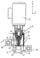
도 1은 본 발명에 따른 방법을 실행하는 장치를 부분적으로 보여주는 단면도이다.1 is a partial cross-sectional view of an apparatus for implementing the method according to the invention.
도 2는 도 1의 장치를 부분적으로 보여주는 상 단면도이다.FIG. 2 is a cross sectional top view partially showing the apparatus of FIG. 1; FIG.
도 3 및 도 4는 본 발명에 따른 장치에서 이용되며 본 발명에 따른 방법을 실행하는 기계적 캐비테이션 장치를 보여주는 도면이다.3 and 4 show a mechanical cavitation device used in the device according to the invention and carrying out the method according to the invention.
도 5 및 도 6은 본 발명에 따른 장치 및 방법에서 이용되는 음향 전력 트랜스듀서를 보여주는 도면이다.5 and 6 show acoustic power transducers used in the apparatus and method according to the present invention.
도 7 및 도 8은 도 5 및 도 6의 음향 전력 트랜스듀서에 이용되는 압전소자를 보여주는 도면이다.7 and 8 illustrate piezoelectric elements used in the acoustic power transducers of FIGS. 5 and 6.
도 1은 액체에 가스를 포함시킴으로써 액체를 처리하는 방법을 실행하는 장치를 도시한다.1 shows an apparatus for implementing a method of treating a liquid by including a gas in the liquid.
액체를 수용하는 공간(12)은 입구(14) 및 출구(16)를 갖는다. 본 예에서, 상기 공간(12)은 하나의 단독실 (sinngle chamber)의 형태를 가진다.The
상기 액체를 처리하는 방법은 통기원리(throughflow principle)에 따라서 수행된다. 즉, 액체는 균일한 유속으로 상기 입구(14)를 통하여 상기 공간(12)으로 흘러들어가고, 상기 출구(16)를 통하여 상기 공간(12)로부터 흘러나온다. 상기 입구(14) 및 상기 출구(16)는 상기 공간(12)에서 대응하는 측에 배치되며 축방향(A)으로 서로 옵셋된다. 동작 시, 장치(10)는 상기 입구(14)가 상기 공간(12)의 하단 에 위치되도록 조절된다.The method of treating the liquid is carried out according to the throughflow principle. That is, liquid flows into the
상기 장치(10)가 동작할 때, 상기 전체 공간(12)은 액체로 완전히 채워진다.When the
상기 입구(14) 근처에는 수평적으로 그리고 회전 가능한 원반 모양의 디스크 형태를 갖는 기계적 캐비테이션 장치(17)가 위치된다. 상기 원반 모양의 디스크는 유동체로서 형성되며, 날카로운 주변 가장자리에서 서로 만나는 대응하는 볼록 측면을 구비한다. 상기 기계적 캐비테에션 소자(17)는 중공형 축(18)에 의하여 연속적으로 제어 가능한 모터(20)에 연결된다. 상기 제어 가능한 모터(20)는 상기 캐비테이션 장치(17)의 회전속도를 결정한다. 상기 캐비테이션 장치(17)는 상기 액체 속에 완전히 함침 되어 액체 속에서 캐비테이션이 발생하도록 빠르게 움직인다.Near the
상기 중공형 축(18) 내측에는, 가스 공급 파이프(21)가 형성된다. (도 1 및 도3 참조). 상기 가스 공급 파이프(21)는 가스 공급 수단의 일부이며, 상기 가스 공급 수단은 가스가 상기 캐비테이션 장치(17)의 표면으로 인도되어 액체 속으로 유입되도록 하는 장치이다. 이를 위하여, 상기 가스 공급 파이프(21)는 상기 공간(12)의 외측에 개방되며 가스 공급기 (도시되지 않음)에 연결될 수 있는 덕트(22)와 연결된다.Inside the
상기 가스는 액화 가스의 온도에 따라 액체형태로 공급될 수 있다. 상기 액화가스가 상기 덕트(22)로 유입될 때 이미 가스형태를 갖는 것이 바람직하다. 액화 산소와 같은 냉각된 액화가스를 사용한다면, 가스 공급 수단이 상기 장치(10) 전체의 냉각과 그에 따른 상기 공간(12) 내의 액체의 냉각에 동시에 기여할 수 있다.The gas may be supplied in liquid form depending on the temperature of the liquefied gas. When the liquefied gas is introduced into the
도 3 및 도 4는 상기 캐비테이션 장치(17)의 구성의 일 예를 보여준다. 상기 캐비테이션 장치(17)는 유동체로서 형성된 디스크의 형태를 가지며, 전면(40)은 상기 후면(42)보다 큰 볼록면의 곡률을 갖는다. 두 개의 타원형의 포켓(44)이 상기 캐비테이션 장치(17)의 전면(40)에 구비된다. 상기 후면(42)은 다수의 포켓(46)이 형성되어 있는데, 상기 다수의 포켓(46)은 주변에서 약간씩 서로 오프셋 되어있으며, 상기 포켓(44)의 영역에서 상기 캐비테이션 장치(11)의 전면(40) 및 상기 후면(42) 사이에 개구부가 형성될 수 있도록 상기 포켓들(44,46)의 깊이가 선택된다. 도 4에서, 이들 양 개구부는 참조번호 48로 표기된다. 이러한 설계에 의하여, 매우 높은 유속이 상기 캐비테이션 장치(17)의 주변 가장자리부의 뿐만 아니라 상기 포켓(44,46)의 영역에 전개된다. 결과적으로, 캐비테이션 효과가 특히 이들 위치에서 매우 높이 나타난다.3 and 4 show an example of the configuration of the
가스 공급 파이프(21)는, 도 3 및 도 4에 도시된 바와 같이, 상기 캐비테이션 장치(17)의 표면에서 바로 개방된다.The
공급될 가스는 상기 덕트(22)를 통하여 유동하며, 상기 덕트(22)는 가로축 홀(25)에 의하여 상기 중공형 축(18)과 연결된다. 상기 모터(20) 및 상기 캐비테이션 장치(17) 사이에 배치된 가스 공급 수단은 이 경우 하우징(23)에 배치되며, 상기 하우징(23)은 상기 중공형 축(18)을 감싸며, 상기 캐비테이션 장치(17)를 상기 모터(20)에 연결시킨다. 상기 가스 공급 파이프(21)는 다수의 개방 채널(50)의 형태로 형성된 출구에 위치하는 상기 캐비테이션 장치(17)의 내측에서 종결되는데, 상기 다수의 개방 채널(50)은 중심축 M을 향해 사선으로 지향되며, 각 채널은 상기 캐비테이션 장치(17)의 표면까지, 특정 예에서는, 상기 포켓(46)의 내측의 표면까 지 연장된다. 상기 가스는 상기 가스 공급 수단을 통하여 운반되어 상기 캐비테이션 장치(17)의 표면에 바로 나타나며 가장 큰 캐비테이션 효과를 갖는 지역의 액체에 유입된다. 개방 채널(50)의 출사각 α (수직선에 대하여 측정된 각)은 본 명세서에서 대략 50도 정도이지만, 어플리케이션의 각 목적에 따라 변경될 수 있음은 물론이다.The gas to be supplied flows through the
상기 캐비테이션 장치의 표면 바로 가까이에서 진행된 것과 같은 가스 공급은, 상기 캐비테이션 장치를 통해서 뿐만 아니라, 다른 장소에서도 효과적으로 실현될 수 있다.Gas supply, such as that which proceeds just near the surface of the cavitation device, can be effectively realized not only through the cavitation device, but also in other places.
상기 캐비테이션 장치(17) 영역에 있는 상기 공간(12)의 단면 (도 1 참조)은 원의 형태를 갖지 않기 때문에, 축대칭을 이루지 않는다. 예를 들어, 상기 공간(12)의 단면은 삼각형, 사각형, 또는 오각형 등의 다각형의 형태를 가질 수 있다. 이것은 상기 캐비테이션 장치(17) 주변에서 와류가 형성되는 것을 막음으로써 캐비테이션 효과를 증가시키는 역할을 한다.Since the cross section (see FIG. 1) of the
상기 공간(12)은 벽(24)에 의해서 에워싸여 상기 공간(12)내의 액체를 보존한다. 상기 공간(12)은 상기 캐비테이션 장치(17)가 배치된 챔버로부터 이격되며, 연결도관을 구비한다.The
본 발명의 상기 공간(12)은 짧은 연결 단편(30,32)들을 구비하며, 상기 짧은 연결 단편(30,32)들은 90도 구부러지며 그것의 각각은 그것에 연결된 음향 전력 트랜스듀서(26,28)들을 구비한다. 상기 짧은 연결 단편(30,32)들은 상기 음향 전력 트랜스듀서(26,28)들을 상기 캐비테이션 장치(17)를 포함하는 챔버에 연결한다. 상 기 음향 전력 트랜스듀서(26,28)들은 본 발명에 따른 초음파 트랜스듀서의 형태를 가지며, 약 400kHz 내지 약 1500kHz의 주파수 범위에서 동작하며, 바람직하게는 약 600kHz 내지 약 1200kHz의 주파수 범위에서 동작한다. 상기 짧은 연결 단편(30)은 상기 챔버의 주변부 방향으로 입구(14)에 대해 90도 오프셋되어 상기 입구(14)의 수준으로 개방되며, 상기 짧은 연결 단편(32)은 출구(16)에 대해 90도 오프셋되어 상기 출구(16)의 수준으로 개방된다. 상기 음향 전력 트랜스듀서(26,28)는 축방향으로 서로 이격되어, 임의의 음향 전력 트랜스듀서의 음파가 타 전력 트랜스듀서에 직접 인가될 수 없도록 한다. 상기 음향 전력 트랜스듀서는 기본파동으로서의 초음파 에너지를 상기 액체 및 상기 캐비테이션 장치(17)에 인가하며, 더욱 상세하게는, 각 디스크 형태를 갖는 전력 트랜스듀서(26,28)의 양측에 인가된다.The
상기 음향 전력 트랜스듀서(26,28) 각각은 다른 주파수를 갖는 스펙트럼을 동시에 방출한다.Each of the
적어도 상기 음향 전력 트랜스듀서(28) 및 선택적으로 상기 음향 전력 트랜스듀서(26)도 마찬가지로 연속적인 동작대신 상기 공간(12), 상기 사용된 가스, 및 상기 사용된 액체의 각 형태에 적합한 펄스 주파수 및 펄스 구간을 가진 펄스형태로 동작한다.At least the
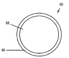
도 5 및 도 8은 상기 음향 전력 트랜스듀서(26,28)에 채용될 수 있는 구성의 일 예를 보여주는 도면이다. 5 and 8 illustrate an example of a configuration that may be employed in the
압전물질로 구성된 디스크 형태의 액추에이터(60)가 하우징(62)안에 배치된다. 여기에서 상기 하우징(62)은 바람직하게 전기적으로 비 도전성 세라믹 또는 플 라스틱 물질로 만들어진다. 양측의 정면(64)은 전기적으로 도전적인 접촉 층, 이 경우, 실버층(66)으로 코팅된다. 상기 가장자리 주변의 원형의 지역을 제외하고, 상기 양측의 정면(64)은 화학적으로 불활성인 보호층(68), 특히 불활성 가스로 코팅되며, 상기 보호층(68)은 액체와 접촉하는 상기 액추에이터(60)의 전체 영역을 커버한다. 상기 전기적 도전층(66)은 상기 압전물질에 접촉시키고 여기 시킨다. 상기 전기적 도전층(66)은 공지된 방법으로 가감 전압 발전기에 연결된다.An actuator 60 in the form of a disk made of piezoelectric material is disposed in the
상기 액추에이터(60)는 상기 보호층(68) 및 상기 전기적 도전층(66) 사이의 전이가 탄성 개스킷(70)에 의해서 밀봉될 수 있도록 상기 하우징(62)에 삽입된다. The
상기 액체가 상기 하우징(62)으로 흘러들어와 상기 액추에이터(60)에 직접적으로 접촉한다. 결과적으로, 상기 음향 전력 트랜스듀서는 상기 음파를 상기 액체에 직접 인가시킬 수 있다.The liquid flows into the
가스를 상기 액체에 함유시키기 위해서, 상기 캐비테이션 장치(17)는 캐비테이션 효과가 상기 액체 속에 발생되도록 매우 빠르게 회전된다. 가스는 상기 가스 공급 수단을 통하여 상기 캐비테이션 장치(17)의 표면에 가이드 된다. 상기 캐비테이션 효과는 유입된 전량의 가스가 상기 액체에 공급되도록 한다. 예를 들어, 상기 유입된 가스의 양은, 15℃의 온도를 갖는 우물물 내의 산소의 경우, 285 g/h가 될 수 있다. 이 경우 평균적인 기포 크기는 여전히 상대적으로 크다. 상기 전체 공간이 상기 음향 전력 트랜스듀서(26,28)의 음파로 가득차 있기 때문에, 상기 캐비테이션에 의해서 발생된 기포는 순간적으로 소리에너지에 의해서 영향을 받으며, 그 과정에서 분리되어, 나노미터 범위의 평균기포사이즈를 갖으며 기포의 대부분은 옴스트롱의 파장 범위에서 발생된다. 이것은 상기 유입된 가스의 대부분이 분자적으로 분산되어 상기 액체에 용해되는 결과를 가져온다. 그러므로 유입된 가스의 대부분이 상대적으로 긴 시간 동안 상기 액체에 남아있게 된다. 이러한 음향화학적 처리는 종래 방법을 이용한 것보다 상기 액체에 용해되는 상기 가스의 비율을 더 증가시킨다. 본 발명에 따른 두 단계의 과정은 상기 캐비테이션 장치(17)를 통하여 가스를 유입시킨 다음 상기 음향 전력 트랜스듀서(26,28)에 의해서 발생된 음파에 의해서 액체 속에 이미 유입된 가스 기포를 처리하는 하는 것이다.In order to contain a gas in the liquid, the
상기 방법은 쓰루 플로우 원리(throughflow principle)로 진행되기 때문에, 도관에 의해서 단지 연결되기만 한 여러 가지 챔버들안에 상기 캐비테이션 장치(17) 및 상기 음향 전력 트랜스듀서(26,28)들 중 하나 또는 전부를 배치시키는 것은 가능하다. 상기 캐비테이션 장치(17) 및 상기 음향 전력 트랜스듀서(26,28)들 사이의 거리는 유체가 이들 사이를 지날 때 10초 이상의 시간이 소요될 정도로 선택되는데, 이 시간은 상기 액체가 하나의 챔버로부터 타챔버로 흐르는데 걸리는 시간이다. 상기 공간(12)의 형태는 전체공간이 상기 음향 전력 트랜스듀서(26,28)들의 음파에 지속적이고 청각적으로 노출되도록 결정되어야 한다. 적절한 반사기가 상기 공간(12)에 배열될 수 있다. Since the method proceeds with the throughflow principle, one or all of the
상기 공간(12)의 형태 및 상기 음향 전력 트랜스듀서(26,28)들의 배치는 상기 공간(12)에서 가능한 한 적은 정지파(standing waves)가 전개되도록 선택된다.The shape of the
도시된 구조에서, 유동의 관점에서 보았을 때, 상기 제1 음향 전력 트랜스듀서(26)는 상기액체가 가스를 다시 함유하기 전에 상기 액체로부터 상기 가스를 제 거하기 위해서 이용된다. 유동하는 액체가 상기 음향 전력 트랜스듀서(26)의 음파에 직접 노출됨으로써, 상기 액체에 이미 용해된 가스가 상기 액체로부터 배출되는 결과를 가져온다. 상기 액체가 상기 캐비테이션 장치(17)에 도달한 후, 특별히 공급된 가스가 다시 상기 액체에 함유된다.In the structure shown, the first
오수 처리 장치로부터의 폐수가 표면수로 배출되는 경우, 상기 폐수가 현재의 기술수준으로 충분히 정화된다고 하더라도, 그것은 건강에 해로우며 강이나 호수를 부유하면서 보건위험을 야기시키는 무수한 영양물, 박테리아, 및 세균을 포함한다. 이러한 이유로, EU 규정은 하수가 일광욕장에서 바다로 배출되는 경우에서도 세균감소에 대하여 정하고 있다.If the wastewater from the sewage treatment system is discharged to surface water, even if the wastewater is sufficiently purified to the present technical level, it is unhealthy and innumerable nutrients, bacteria, and bacteria that cause health risks while floating rivers or lakes It includes. For this reason, EU regulations provide for bacterial reduction even when sewage is discharged from the solarium into the sea.
상기 장치(10) 및 상기 장치(10)와 함께 실행되는 방법을 적용하는 일 목적은 물, 특히 폐수를 정화하는데 있다. 예를 들어, 상기 장치(10)는 오수 처리 장치에서 폐수를 처리하기 위하여 채용될 수 있다.One purpose of applying the
이를 위하여, 바람직하게는, 공급되는 가스는 순수 산소나 시작가스로서 이용될 수 있는 공기와 함께 오존을 포함한다.For this purpose, the gas supplied preferably comprises ozone with pure oxygen or air which can be used as starting gas.
상기 오존을 발생시키기 위하여, 자외선이 상기 가스 공급 수단 지역에 조사된다. 예를 들어, 이러한 자외선은 상기 덕트(22) 또는 상기 중공형 축(18)의 지역에 구비되는 자외선램프에 의해서 조사된다. 상기 자외선램프를 사용하는 것 대신, X-선 또는 감마선이 조사될 수 있다. 모든 경우에서, 높은 에너지의 방사는 산소의 일부가 오존으로 변환되는 결과를 가져온다. 상기 오존이 가스의 출구 바로 근처에서 발생되기 때문에, 오존을 생성하고 오존을 액체로 유입하는 동안 오존이 분해되 는 문제가 존재하지 않는다. 또한 기존의 오존 발생기에 의해서 상기 오존을 발생하여 그것을 폐수에 공급할 수 있다.In order to generate the ozone, ultraviolet rays are irradiated to the gas supply means region. For example, such ultraviolet rays are irradiated by ultraviolet lamps provided in the region of the
상기 가스는 시스템에 액체형태, 예를 들어 액화산소의 형태로 공급될 수 있다. 상기 액화 산소가 상기 덕트(22)에 유입되는 경우, 상기 액화 산소는 이미 가스 형태로 존재하는 것이 바람직하다.The gas can be supplied to the system in liquid form, for example in the form of liquefied oxygen. When the liquefied oxygen flows into the
바람직하게는, 상기 오존은 초음파에 의해서 처리되면서, 상기 액체에 분자적으로 분산되어 용해됨으로써 세균이 상기 액체로부터 신뢰성 있게 제거되도록 한다. 단백질, 독소뿐만 아니라 박테리아, 바이러스, 곰팡이 포자에 덧붙여, 특히 내분비물을 교란시키는 물질이 확실하게 파괴된다. 상기 단백질은 변성, 즉 단백질 분자의 특정 화학그룹과 오존과의 반응에 의한 공지된 방법에 의해서 파괴된다.Preferably, the ozone is molecularly dispersed and dissolved in the liquid while being treated by ultrasonic waves to ensure that bacteria are reliably removed from the liquid. In addition to proteins, toxins, as well as bacteria, viruses, and fungal spores, certain substances that disrupt the endocrine, in particular, are reliably destroyed. The protein is destroyed by known methods by denaturation, ie reaction of certain chemical groups of protein molecules with ozone.
기포 사이즈가 매우 작아지기 때문에, 본 발명에 따른 방법은 기존의 방법과 비교하여 더 오랜 시간 동안 가스가 용해된 상태로 남아 있다. 몇 옹스트롬 또는 나노미터의 직경을 갖는 기포는 바로 액체 표면 위로 상승하는 큰 크기의 가스 기포로서 더 이상 작용하지 않으며, 어떤 경우에는 물보다 무거워 바닥으로 가라앉는다. 또한 상기 기포들은 더 큰 기포보다 더 오랫동안 물속에서 남아 있다. 상기 더 큰 기포와는 반대로, 수 옹스트롬 내지 나노미터의 크기를 갖는 기포들의 경우, 기포의 내부 압력은 액체 속의 대기 압력과 거의 같다. 또한, 상기 작은 크기의 기포들은 더 큰 기포를 형성하기 위하여 서로 결합되는 경향이 현저하게 낮아져, 가장 작은 기포들의 성분이 매우 오랜 시간 동안 액체 속에 함유되어 남아 있게 된다.Since the bubble size becomes very small, the process according to the invention remains dissolved in the gas for a longer time compared to the conventional process. Bubbles with a diameter of several angstroms or nanometers no longer act as large gas bubbles that rise directly above the liquid surface, and in some cases are heavier than water and sink to the bottom. The bubbles also remain in water for longer than larger bubbles. In contrast to the larger bubbles, for bubbles having a size of several angstroms to nanometers, the internal pressure of the bubbles is approximately equal to the atmospheric pressure in the liquid. In addition, the small bubbles have a significantly lower tendency to bond with each other to form larger bubbles, so that the components of the smallest bubbles remain contained in the liquid for a very long time.
먼저, 이것은 물속의 물질들이 오존과 오랜 시간 동안 반응하게 하고, 두 번 째로, 상기 액체 속의 가스 기포의 정교한 분포가 넓은 반응 표면을 낳게 한다. 이들 요소들은 본 발명에 따른 방법이 기존 방법과 비교하여 현저하게 개선된 효과를 낳게 한다.First, this causes the substances in the water to react with the ozone for a long time, and secondly, the elaborate distribution of gas bubbles in the liquid results in a wide reaction surface. These elements make the method according to the invention have a markedly improved effect compared to the existing method.
본 발명의 방법에 따르면, 상기 가스의 상기 액체 속의 용해가 현저히 증가하여 옹스트롬 또는 나노미터 범위에서 최소 사이즈를 갖는 기포의 분산을 가능하게 한다.According to the method of the present invention, the dissolution of the gas in the liquid is significantly increased to enable dispersion of bubbles having a minimum size in the angstrom or nanometer range.
Claims (22)
Applications Claiming Priority (5)
| Application Number | Priority Date | Filing Date | Title |
|---|---|---|---|
| DE102006061906.4 | 2006-12-28 | ||
| DE102006061906 | 2006-12-28 | ||
| DE102007013533A DE102007013533A1 (en) | 2006-12-28 | 2007-03-21 | Method and apparatus for dissolving gases in liquids comprises sonochemical dispersion of oxygen or ozone in liquid to kill, bacteria and viruses by targeted oxidation |
| DE102007013533.7 | 2007-03-21 | ||
| PCT/EP2007/011456 WO2008080618A1 (en) | 2006-12-28 | 2007-12-28 | Method and device for treating a liquid |
Publications (2)
| Publication Number | Publication Date |
|---|---|
| KR20090106403A true KR20090106403A (en) | 2009-10-08 |
| KR101430725B1 KR101430725B1 (en) | 2014-08-14 |
Family
ID=39247788
Family Applications (1)
| Application Number | Title | Priority Date | Filing Date |
|---|---|---|---|
| KR1020097015850A KR101430725B1 (en) | 2006-12-28 | 2007-12-28 | Method and device for treating a liquid |
Country Status (20)
| Country | Link |
|---|---|
| US (1) | US8329043B2 (en) |
| EP (1) | EP2125174B1 (en) |
| JP (1) | JP5219096B2 (en) |
| KR (1) | KR101430725B1 (en) |
| CN (1) | CN101626822B (en) |
| AT (1) | ATE496685T1 (en) |
| AU (1) | AU2007341626B2 (en) |
| BR (1) | BRPI0720632A2 (en) |
| CA (1) | CA2673656C (en) |
| DE (2) | DE102007013533A1 (en) |
| DK (1) | DK2125174T3 (en) |
| IL (1) | IL199499A (en) |
| MA (1) | MA31101B1 (en) |
| MX (1) | MX2009006925A (en) |
| PL (1) | PL2125174T3 (en) |
| PT (1) | PT2125174E (en) |
| SI (1) | SI2125174T1 (en) |
| TN (1) | TN2009000264A1 (en) |
| WO (1) | WO2008080618A1 (en) |
| ZA (1) | ZA200904778B (en) |
Families Citing this family (11)
| Publication number | Priority date | Publication date | Assignee | Title |
|---|---|---|---|---|
| DE102010047947A1 (en) * | 2010-10-08 | 2012-04-12 | Ultrasonic Systems Gmbh | Apparatus for treating a liquid and method for treating a suspension |
| CN102452699A (en) * | 2010-10-18 | 2012-05-16 | 四平市铁东区庆升热工设备有限公司 | Reactor for flowing ultrasonic cavitation degradation of high-concentration printing and dyeing sewage |
| US9169136B1 (en) * | 2011-06-16 | 2015-10-27 | Water Evolution Technologies, Inc. | Water purification and softening system and method for beverage dispenser |
| DE102011121910A1 (en) * | 2011-12-21 | 2013-06-27 | Ultrasonic Systems Gmbh | Process for the treatment of sulfide-containing waste liquor |
| US20140353223A1 (en) * | 2011-12-29 | 2014-12-04 | Daikin Industries, Ltd. | Purifying device |
| DE102012018995A1 (en) * | 2012-09-27 | 2014-03-27 | Klaus Büttner | Process for the treatment of a liquid |
| US20140263461A1 (en) * | 2013-03-13 | 2014-09-18 | David M. Prokop | Motorized aerator pourer |
| CN104437197B (en) * | 2014-11-21 | 2017-02-22 | 中国科学院力学研究所 | Spatial two-phase ultrasonic mixing and stirring system |
| FI127076B (en) * | 2016-04-14 | 2017-10-31 | Nofa Oy | A cavitation arrangement for removing harmful material from the fluid |
| US20220098067A1 (en) * | 2020-09-25 | 2022-03-31 | Ovivo Inc. | Enhanced Membrane Performance Using Ozone |
| CN117304387B (en) * | 2023-09-25 | 2024-04-23 | 上海拓径新材料科技股份有限公司 | Polymerizable near infrared dye, preparation method and polymerization equipment |
Family Cites Families (28)
| Publication number | Priority date | Publication date | Assignee | Title |
|---|---|---|---|---|
| CH283308A (en) | 1948-03-12 | 1952-05-31 | Mueller Hans | Device for mixing a liquid or for emulsifying. |
| US4003832A (en) * | 1974-01-07 | 1977-01-18 | Tii Corporation | Method of applying ozone and sonic energy to sterilize and oxidize waste water |
| CH593870A5 (en) * | 1974-01-07 | 1977-12-15 | Tii Corp | |
| US4298467A (en) * | 1977-06-06 | 1981-11-03 | Panlmatic Company | Water treatment system |
| NL7803906A (en) * | 1978-04-12 | 1979-10-16 | Noordvos Schroeven Bv | METHOD, DEVICE AND PROPELLER FOR DISTRIBUTING A GAS, POWDER OR LIQUID MATERIAL IN A LIQUID. |
| JPS5934130B2 (en) | 1980-07-02 | 1984-08-20 | セントラル硝子株式会社 | Manufacturing method of silicon tetrafluoride |
| JPS57171414A (en) * | 1981-04-14 | 1982-10-22 | Matsushita Electric Ind Co Ltd | Gas scrubbing apparatus |
| SU1240439A1 (en) * | 1984-12-10 | 1986-06-30 | Fedotkin Igor M | Cavitation mixer |
| US4952417A (en) * | 1987-02-09 | 1990-08-28 | Ramon Escola Gallart | Apparatus for incorporating gas into a sugar mass |
| JPH04161296A (en) | 1990-10-25 | 1992-06-04 | Sanbio:Kk | Air bubble generator |
| DE4113578A1 (en) | 1991-04-25 | 1992-10-29 | Poeschl Guenter | DEVICE FOR LOADING VISCOSE LIQUIDS WITH GASES |
| FR2679790A1 (en) | 1991-08-02 | 1993-02-05 | Billmann Andre | Physicochemical reactor with ultrasonic cavitation |
| JP3104143B2 (en) * | 1992-02-14 | 2000-10-30 | 耕司 戸田 | Ultrasonic stirrer |
| GB9408816D0 (en) | 1994-05-04 | 1994-06-22 | Boc Group Plc | Gas dissolution in liquids |
| JP3532626B2 (en) * | 1994-10-07 | 2004-05-31 | アロカ株式会社 | Stirring nozzle device |
| JP4066468B2 (en) * | 1997-02-17 | 2008-03-26 | 株式会社Ihi | Air ozone mixer and ozone fog generator |
| US5925290A (en) * | 1997-08-08 | 1999-07-20 | Rhone-Poulenc Inc. | Gas-liquid venturi mixer |
| US6491829B2 (en) * | 1999-12-24 | 2002-12-10 | Takashi Nishimoto | Method and unit for processing contaminated liquid |
| JP3762206B2 (en) * | 2000-09-13 | 2006-04-05 | 株式会社アスプ | Ultra-fine bubble generator |
| JP2004000897A (en) | 2002-04-01 | 2004-01-08 | Atsushi Ichiki | Apparatus for generating minute bubble |
| US6974305B2 (en) * | 2002-09-26 | 2005-12-13 | Garrett Iii Norman H | Roto-dynamic fluidic systems |
| DE10258898A1 (en) * | 2002-12-17 | 2004-07-01 | Institut für Energetik und Umwelt gGmbH | Inactivation of microorganisms using cavitation generator, introduces high level of destructive ultrasonic energy into fluid containing them |
| US7048863B2 (en) * | 2003-07-08 | 2006-05-23 | Ashland Licensing And Intellectual Property Llc | Device and process for treating cutting fluids using ultrasound |
| ES2309549T3 (en) | 2003-08-08 | 2008-12-16 | Klaus Buttner | PROCEDURE FOR FLUID DISINFECTION. |
| DE102004002545A1 (en) * | 2004-01-17 | 2005-08-18 | Water System Cleaning Ag | Water treatment system for supply of water to households and industrial users has rotating magnetic disc |
| DE202004020459U1 (en) * | 2004-06-28 | 2005-07-14 | Büttner, Klaus, Dipl.-Ing. | Treating aqueous liquids to reduce toxin levels comprises sonicating the liquid to generate hydroxyl radicals |
| JP4970774B2 (en) | 2004-11-24 | 2012-07-11 | 昭和電工株式会社 | Bubbling discharge dispersion device, molten metal processing method and molten metal processing device |
| JP2006289183A (en) * | 2005-04-06 | 2006-10-26 | Nano Bubble Kk | Nano-bubble forming method and apparatus |
-
2007
- 2007-03-21 DE DE102007013533A patent/DE102007013533A1/en not_active Withdrawn
- 2007-12-28 AT AT07857148T patent/ATE496685T1/en active
- 2007-12-28 BR BRPI0720632-1A2A patent/BRPI0720632A2/en not_active Application Discontinuation
- 2007-12-28 DE DE502007006399T patent/DE502007006399D1/en active Active
- 2007-12-28 PL PL07857148T patent/PL2125174T3/en unknown
- 2007-12-28 MX MX2009006925A patent/MX2009006925A/en active IP Right Grant
- 2007-12-28 PT PT07857148T patent/PT2125174E/en unknown
- 2007-12-28 WO PCT/EP2007/011456 patent/WO2008080618A1/en active Application Filing
- 2007-12-28 DK DK07857148.6T patent/DK2125174T3/en active
- 2007-12-28 AU AU2007341626A patent/AU2007341626B2/en not_active Ceased
- 2007-12-28 SI SI200730576T patent/SI2125174T1/en unknown
- 2007-12-28 CN CN200780048647XA patent/CN101626822B/en active Active
- 2007-12-28 JP JP2009543398A patent/JP5219096B2/en not_active Expired - Fee Related
- 2007-12-28 KR KR1020097015850A patent/KR101430725B1/en not_active IP Right Cessation
- 2007-12-28 US US12/521,528 patent/US8329043B2/en active Active
- 2007-12-28 EP EP07857148A patent/EP2125174B1/en active Active
- 2007-12-28 CA CA2673656A patent/CA2673656C/en active Active
-
2009
- 2009-06-23 IL IL199499A patent/IL199499A/en not_active IP Right Cessation
- 2009-06-24 TN TNP2009000264A patent/TN2009000264A1/en unknown
- 2009-07-08 ZA ZA200904778A patent/ZA200904778B/en unknown
- 2009-07-16 MA MA32102A patent/MA31101B1/en unknown
Also Published As
| Publication number | Publication date |
|---|---|
| PL2125174T3 (en) | 2011-06-30 |
| DE502007006399D1 (en) | 2011-03-10 |
| ATE496685T1 (en) | 2011-02-15 |
| BRPI0720632A2 (en) | 2014-03-25 |
| DE102007013533A1 (en) | 2008-07-03 |
| US8329043B2 (en) | 2012-12-11 |
| DK2125174T3 (en) | 2011-05-16 |
| CN101626822A (en) | 2010-01-13 |
| CA2673656A1 (en) | 2008-07-10 |
| ZA200904778B (en) | 2010-04-28 |
| EP2125174B1 (en) | 2011-01-26 |
| PT2125174E (en) | 2011-05-02 |
| CN101626822B (en) | 2013-01-16 |
| TN2009000264A1 (en) | 2010-10-18 |
| CA2673656C (en) | 2016-03-01 |
| AU2007341626B2 (en) | 2012-01-19 |
| KR101430725B1 (en) | 2014-08-14 |
| US20100314331A1 (en) | 2010-12-16 |
| MA31101B1 (en) | 2010-01-04 |
| WO2008080618A1 (en) | 2008-07-10 |
| JP5219096B2 (en) | 2013-06-26 |
| JP2010514552A (en) | 2010-05-06 |
| SI2125174T1 (en) | 2011-06-30 |
| EP2125174A1 (en) | 2009-12-02 |
| AU2007341626A1 (en) | 2008-07-10 |
| IL199499A (en) | 2013-01-31 |
| MX2009006925A (en) | 2009-10-12 |
Similar Documents
| Publication | Publication Date | Title |
|---|---|---|
| KR101430725B1 (en) | Method and device for treating a liquid | |
| EP1403221B1 (en) | Water purifier | |
| WO2000058824A1 (en) | Method and system for consistent cluster operational data in a server cluster using a quorum of replicas | |
| US20130248429A1 (en) | Device for purifying water | |
| US6818128B2 (en) | Apparatus for directing ultrasonic energy | |
| JP2009131827A (en) | Method for treating sewage | |
| KR101629202B1 (en) | Ship for removing green or red tides using plasma | |
| US6896819B2 (en) | Method for water treatment utilizing a liquid/vacuum cyclone interface apparatus | |
| US7846341B2 (en) | Method of ultrasonically treating a continuous flow of fluid | |
| KR20090094293A (en) | Ultrasonic method and device for treating a continuous flow of fluid | |
| JP2004337665A (en) | Water treatment apparatus | |
| KR20040111598A (en) | Double-walled chamber for ultraviolet radiation treatment of liquids | |
| JP2011189240A (en) | Cyclone type water treatment device | |
| JP5023481B2 (en) | Liquid processing method and liquid processing apparatus | |
| JP4694553B2 (en) | Water treatment apparatus and water treatment method | |
| WO2000058224A1 (en) | Reactor for cleaning and disinfection of aquatic media | |
| JP4357316B2 (en) | Wastewater treatment equipment | |
| JP4921431B2 (en) | Ultrasonic treatment equipment | |
| JP2004202322A (en) | Ultrasonic treatment method and apparatus | |
| JP4247150B2 (en) | Ultrasonic disinfection and decomposition equipment | |
| JP2004202321A (en) | Water treatment apparatus | |
| RU130601U1 (en) | ULTRASONIC CAVITATION REACTOR FOR WATER TREATMENT AND DISINFECTION | |
| JPH11262515A (en) | Sterilizer | |
| JP2004148137A (en) | Sludge solubilizing apparatus | |
| WO2008048015A1 (en) | Energy-activating apparatus using ultrasonic vibration |
Legal Events
| Date | Code | Title | Description |
|---|---|---|---|
| A201 | Request for examination | ||
| E902 | Notification of reason for refusal | ||
| E701 | Decision to grant or registration of patent right | ||
| FPAY | Annual fee payment |
Payment date: 20171030 Year of fee payment: 4 |
|
| LAPS | Lapse due to unpaid annual fee |