KR102493737B1 - System and method for tracking vehicles in parking structures and intersections - Google Patents
System and method for tracking vehicles in parking structures and intersections Download PDFInfo
- Publication number
- KR102493737B1 KR102493737B1 KR1020167035568A KR20167035568A KR102493737B1 KR 102493737 B1 KR102493737 B1 KR 102493737B1 KR 1020167035568 A KR1020167035568 A KR 1020167035568A KR 20167035568 A KR20167035568 A KR 20167035568A KR 102493737 B1 KR102493737 B1 KR 102493737B1
- Authority
- KR
- South Korea
- Prior art keywords
- vehicle
- electromagnetic radiation
- parking
- retroreflective
- parking space
- Prior art date
Links
Images


Classifications
-
- G—PHYSICS
- G06—COMPUTING; CALCULATING OR COUNTING
- G06V—IMAGE OR VIDEO RECOGNITION OR UNDERSTANDING
- G06V10/00—Arrangements for image or video recognition or understanding
- G06V10/20—Image preprocessing
- G06V10/24—Aligning, centring, orientation detection or correction of the image
- G06V10/245—Aligning, centring, orientation detection or correction of the image by locating a pattern; Special marks for positioning
-
- G—PHYSICS
- G06—COMPUTING; CALCULATING OR COUNTING
- G06V—IMAGE OR VIDEO RECOGNITION OR UNDERSTANDING
- G06V20/00—Scenes; Scene-specific elements
- G06V20/50—Context or environment of the image
- G06V20/52—Surveillance or monitoring of activities, e.g. for recognising suspicious objects
-
- G—PHYSICS
- G08—SIGNALLING
- G08G—TRAFFIC CONTROL SYSTEMS
- G08G1/00—Traffic control systems for road vehicles
- G08G1/01—Detecting movement of traffic to be counted or controlled
-
- G—PHYSICS
- G08—SIGNALLING
- G08G—TRAFFIC CONTROL SYSTEMS
- G08G1/00—Traffic control systems for road vehicles
- G08G1/07—Controlling traffic signals
-
- G—PHYSICS
- G08—SIGNALLING
- G08G—TRAFFIC CONTROL SYSTEMS
- G08G1/00—Traffic control systems for road vehicles
- G08G1/07—Controlling traffic signals
- G08G1/08—Controlling traffic signals according to detected number or speed of vehicles
-
- G—PHYSICS
- G08—SIGNALLING
- G08G—TRAFFIC CONTROL SYSTEMS
- G08G1/00—Traffic control systems for road vehicles
- G08G1/09—Arrangements for giving variable traffic instructions
-
- G—PHYSICS
- G08—SIGNALLING
- G08G—TRAFFIC CONTROL SYSTEMS
- G08G1/00—Traffic control systems for road vehicles
- G08G1/09—Arrangements for giving variable traffic instructions
- G08G1/095—Traffic lights
-
- G—PHYSICS
- G08—SIGNALLING
- G08G—TRAFFIC CONTROL SYSTEMS
- G08G1/00—Traffic control systems for road vehicles
- G08G1/14—Traffic control systems for road vehicles indicating individual free spaces in parking areas
- G08G1/141—Traffic control systems for road vehicles indicating individual free spaces in parking areas with means giving the indication of available parking spaces
- G08G1/142—Traffic control systems for road vehicles indicating individual free spaces in parking areas with means giving the indication of available parking spaces external to the vehicles
Abstract
동적 신호 대 잡음비 추적 시스템은 추적 시스템의 시야 내에 있는 차량의 검출을 가능하게 한다. 추적 시스템은, 구역 내에 전자기 방사를 방출하도록 구성되는 방출기, 구역 내의 차량으로부터 되반사되는 전자기 방사를 검출하도록 구성되는 검출기, 및 검출기로부터의 신호를 평가하도록 그리고 이 평가의 결과로서 다양한 디바이스를 제어하도록 구성되는 제어 유닛을 포함할 수도 있다.A dynamic signal-to-noise ratio tracking system enables detection of vehicles within the field of view of the tracking system. The tracking system includes an emitter configured to emit electromagnetic radiation within the zone, a detector configured to detect electromagnetic radiation reflected back from vehicles within the zone, and a signal from the detector to evaluate and control various devices as a result of the evaluation. It may also include a configured control unit.

Description
관련 출원에 대한 교차 참조Cross reference to related applications
본 출원은 2014년 5월 21일자로 출원된 미국 가출원 제 62/001,551호의 이익을 주장하는데, 상기 가출원은 그 전체가 참조에 본원에 통합된다.This application claims the benefit of US Provisional Application No. 62/001,551, filed May 21, 2014, which is incorporated herein by reference in its entirety.
배경background
본 개시는 일반적으로 추적 시스템의 분야에 관한 것으로, 특히, 동적 신호 대 잡음비 추적 시스템을 통해 다양한 환경(context)에서 엘리먼트의 추적을 가능하게 하기 위해 사용되는 방법 및 기기(equipment)에 관한 것이다.The present disclosure relates generally to the field of tracking systems, and more particularly to methods and equipment used to enable tracking of elements in a variety of contexts via dynamic signal-to-noise ratio tracking systems.
추적 시스템은, 아주 다양한 환경에서, 다른 양태 중에서도, 오브젝트의 모션, 포지션, 방위, 및 거리를 추적하기 위해 널리 사용되어 왔다. 이러한 현존하는 추적 시스템은, 일반적으로, 전자기 에너지를 방출하는 방출기 및 전자기 에너지를, 가끔은 전자기 에너지가 오브젝트로부터 반사된 후, 검출하도록 구성되는 검출기를 포함한다. 오늘 날, 종래의 추적 시스템은 소정의 단점을 갖는다는 것 및, 다른 것들 중에서도, 놀이 공원 어트랙션(amusement park attraction), 작업장 모니터링, 스포츠, 불꽃 놀이, 공장 현장 관리(factory floor management), 로봇 공학, 보안 시스템, 주차장, 및 운송을 비롯한 다양한 환경에서의 사용을 위해 향상된 추적 시스템이 소망된다는 것이 인식된다.Tracking systems have been widely used in a wide variety of environments to track the motion, position, orientation, and distance of objects, among other aspects. These existing tracking systems typically include an emitter that emits electromagnetic energy and a detector configured to detect the electromagnetic energy, often after the electromagnetic energy is reflected from an object. Today, conventional tracking systems have certain drawbacks and are used in, among other things, amusement park attractions, workplace monitoring, sports, fireworks, factory floor management, robotics, It is recognized that an improved tracking system is desired for use in a variety of environments including security systems, parking lots, and transportation.
간단한 설명brief explanation
본 개시의 실시형태에 따르면, 차량 교통 제어 시스템은, 전자기 방사를 검출 구역으로 방출하도록 구성되는 방출기, 검출 구역 내의 역반사 엘리먼트로부터의 방출된 전자기 방사의 역반사로부터 유래하는 역반사된 전자기 방사를 검출하도록 구성되는 검출기, 및 방출기 및 검출기에 통신 가능하게 커플링되는 제어 회로부를 포함할 수도 있다. 제어 회로부는, 검출기에 의해 검출되는 역반사된 전자기 방사를 모니터링하도록 그리고 모니터링된 역반사된 전자기 방사에 기초하여 검출 구역 내의 하나 이상의 차량에 관한 정보를 평가하도록 구성된다. 시스템은 또한, 제어 회로부에 통신 가능하게 커플링되며 검출 구역의 하나 이상의 차량에 관한 유저 인지가능 표시를 제공하도록 구성된다. 제어 회로부는 하나 이상의 차량에 관한 평가된 정보에 기초하여 자동화된 디바이스가 특정한 유저 인지가능 표시를 제공하게 하도록 구성된다.According to an embodiment of the present disclosure, a vehicular traffic control system provides retroreflected electromagnetic radiation resulting from retroreflection of emitted electromagnetic radiation from an emitter configured to emit electromagnetic radiation into a detection zone, a retroreflective element in the detection zone. a detector configured to detect and control circuitry communicatively coupled to the emitter and detector. The control circuitry is configured to monitor retroreflected electromagnetic radiation detected by the detector and to evaluate information about one or more vehicles in the detection zone based on the monitored retroreflected electromagnetic radiation. The system is also communicatively coupled to the control circuitry and configured to provide a user perceivable indication regarding one or more vehicles in the detection zone. The control circuitry is configured to cause the automated device to provide certain user perceptible indications based on the evaluated information about the one or more vehicles.
본 개시의 다른 실시형태에 따르면, 차량의 움직임을 추적 및 제어하는 방법은, 방출기를 사용하여 전자기 방사로 검출 구역 - 검출 구역은 차량 경로 또는 주차 구조물의 일부에 대응함 - 을 가득 비추는 것, 검출기를 사용하여 검출 구역 내에서부터 역반사되는 전자기 방사를 검출하는 것, 적어도 검출기에 통신 가능하게 커플링되는 제어 회로부를 사용하여 검출 구역 내의 하나 이상의 차량에 관한 정보를 평가하기 위해 역반사된 전자기 방사를 모니터링하는 것; 및 검출 구역 내의 차량의 움직임에 영향을 주기 위해 제어 회로부를 사용하여, 평가된 차량 정보에 적어도 부분적으로 기초하여 자동화된 디바이스를 제어하는 것을 포함한다.According to another embodiment of the present disclosure, a method for tracking and controlling the movement of a vehicle includes flooding a detection zone, the detection zone corresponding to a vehicle path or part of a parking structure, with electromagnetic radiation using an emitter, a detector detecting retroreflected electromagnetic radiation from within the detection zone using at least control circuitry communicatively coupled to the detector to monitor the retroreflected electromagnetic radiation to evaluate information about one or more vehicles within the detection zone. to do; and controlling the automated device based at least in part on the evaluated vehicle information, using the control circuitry to affect movement of the vehicle within the detection zone.
본 개시의 다른 실시형태에 따르면, 차량 교통 제어 시스템은, 역반사된 전자기 방사를 모니터링하고 역반사 전자기 방사를 검출 구역 내의 역반사 엘리먼트와 관련시키도록, 역반사된 전자기 방사에서의 변화를 식별하고 식별된 변화를 차량 정보와 관련시키도록; 차량의 움직임, 차량의 사이즈, 차량의 형상, 차량의 포지션, 또는 이들이 조합을 결정하기 위해 차량을 평가하도록; 그리고 검출 구역 내에서의 차량의 움직임 또는 차량의 포지션, 또는 이들 둘 다와 관련되는 디스플레이 또는 출력을 제공하기 위해, 평가된 차량 정보에 적어도 부분적으로 기초하여 자동화된 디바이스를 제어하도록 구성되는 제어 회로부를 포함한다.According to another embodiment of the present disclosure, a vehicle traffic control system is configured to monitor retroreflected electromagnetic radiation and identify changes in retroreflected electromagnetic radiation to associate the retroreflected electromagnetic radiation with retroreflective elements within a detection zone. associate the identified change with vehicle information; evaluate the vehicle to determine the movement of the vehicle, the size of the vehicle, the shape of the vehicle, the position of the vehicle, or a combination thereof; and control circuitry configured to control the automated device based at least in part on the evaluated vehicle information to provide a display or output relating to vehicle motion or vehicle position within the detection zone, or both. include
도면
본 개시의 이들 및 다른 피쳐, 양태, 및 이점은, 동일한 도면 부호가 도면 전체에 걸쳐 동일한 부분을 나타내는 첨부의 도면을 참조하여 하기의 상세한 설명을 읽을 때 가장 잘 이해될 것인데, 도면에서:
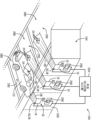
도 1은, 본 개시의 실시형태에 따른, 오브젝트를 추적하기 위해 동적 신호 대 잡음비 디바이스를 활용하는 추적 시스템의 개략도이다;
도 2는, 본 개시의 실시형태에 따른, 오브젝트를 추적하기 위해 동적 신호 대 잡음비 디바이스를 활용하는 다른 추적 시스템의 개략도이다;
도 3은, 본 개시의 실시형태에 따른, 사람의 역반사 마커를 추적하는 도 1의 추적 시스템의 개략도이다;
도 4는, 본 개시의 실시형태에 따른, 사람 또는 오브젝트의 포지션 및 움직임이 공간 및 시간적으로 추적되는 도 1의 추적 시스템에 의해 수행되는 분석의 개략적인 표현이다;
도 5는, 본 개시의 실시형태에 따른, 도 1의 추적 시스템을 통해 방(room) 안의 사람들의 포지션을 추적하기 위한 역반사 마커의 그리드 패턴을 갖는 방의 조감도(overhead view)이다;
도 6은, 본 개시의 실시형태에 따른, 역반사 마커 움직임의 추적 없이 그리고 역반사 마커 폐색(occlusion)의 추적 없이 사람을 추적하는 도 1의 추적 시스템의 입면도(elevational view)이다;
도 7은, 본 개시의 실시형태에 따른, 도 1의 추적 시스템을 통해 방 안의 사람들 및 오브젝트의 포지션을 추적하기 위한 방의 벽 및 플로어에 배치되는 역반사 마커의 그리드 패턴을 갖는 방의 측면도이다;
도 8은, 본 개시의 실시형태에 따른, 상이한 파장의 전자기 방사가 도 1의 추적 시스템의 검출기를 향해 되반사되는(reflected back) 것을 가능하게 하는 상이한 코팅을 갖는 역반사 마커의 단면도를 예시한다;
도 9a 내지 도 9c는, 본 개시의 실시형태에 따른, 오브젝트가 도 1의 추적 시스템에 의해 세 개의 공간 차원에서 추적될 수도 있는 방식을 묘사한다;
도 10은, 본 개시의 실시형태에 따른, 도 1의 추적 시스템을 사용하여 추적된 반사에 기초하여 반사를 추적하고 놀이 공원 엘리먼트(amusement park element)를 제어하는 방법의 실시형태를 예시하는 흐름도이다;
도 11은, 본 개시의 실시형태에 따른, 도 1의 추적 시스템을 사용하여, 차량 정보를 평가하기 위해 반사를 추적하는 그리고 평가된 정보에 기초하여 놀이 공원 엘리먼트를 제어하는 방법의 실시형태를 예시하는 흐름도이다;
도 12는, 본 개시의 실시형태에 따른, 교차로 및 주차 구조물에서 차량 정보를 모니터링하기 위해 그리고 차량 움직임 및 포지션에 영향을 줄 차량 정보에 기초하여 놀이 공원 엘리먼트를 제어하기 위해 추적 시스템을 활용하는 놀이 공원 구역의 개략도이다;
도 13은, 본 개시의 실시형태에 따른, 도로 교차로의 조감도 및 교통을 제어하기 위해 추적 시스템이 교차로에 통합될 수도 있는 방식의 실시형태이다;
도 14는, 본 개시의 실시형태에 따른, 도 13의 교차로와 관련되는 신호등에 통합되는 추적 시스템의 확대도이다;
도 15는, 본 개시의 실시형태에 따른, 차량이 개방형 주차장(open parking)으로 향하게 되는지 또는 차고 주차장(garage parking)으로 향하게 되는지의 여부를 제어하는 진입 시스템에 통합되는 추적 시스템의 조감도이다;
도 16은, 본 개시의 실시형태에 따른, 차량에 관한 정보를 평가하기 위해 그리고 평가에 기초하여 주차 추천을 제공하기 위해 추적 시스템을 활용하는 주차 안내 시스템(parking advisory system)의 사시도이다;
도 17은, 본 개시의 실시형태에 따른, 차고 주차 구조물을 통과하는 차량의 움직임을 평가하기 위해 그리고 평가에 기초하여 주차 구조물 내의 운전자(driver)에게 시각적 표시를 제공하기 위해 추적 시스템을 활용하는 차고 교통 제어 시스템(garage traffic control system)의 사시도이다;
도 18은, 본 개시의 실시형태에 따른, 소정의 주차 공간(parking space)이 점유되었는지의 여부를 평가하기 위해, 그리고 운전자가 자신의 차량을 주차 공간에 주차함에 있어서 운전자를 지원하기 위해, 복수의 추적 시스템을 활용하는 차량 지원 시스템(vehicle assistance system)의 사시도이다;
도 19는, 본 개시의 실시형태에 따른, 추적 시스템이 공간 내의 차량의 포지션을 평가하는 것을 가능하게 하기 위해 주차 공간의 분리 라인에 근접하게 배치되는 역반사 마커를 갖는 주차 공간의 조감도이다;
도 20은, 본 개시의 실시형태에 따른, 차고 주차 구조물 내에서의 그리고 게스트가 자신의 차량을 사용하여 지원을 요청할 수도 있는지의 여부를 평가하기 위해 추적 시스템을 활용하는 차량 지원 시스템의 사시도이다;
도 21은, 본 개시의 실시형태에 따른, 게스트가 지원을 위해 신호를 보내고 있는지의 여부를 도 20의 추적 시스템이 평가하는 것을 가능하게 하는 다수의 역반사 마커를 갖는 차량 태그의 확대도이다; 그리고
도 22는, 본 개시의 실시형태에 따른, 공원 어트랙션 구역 내에 있는 그리고 게스트 및/또는 서비스 차량의 포지션을 평가하기 위해 그리고 평가된 포지션에 기초하여 다양한 통로에 대한 액세스를 제어하기 위해 복수의 추적 시스템을 활용하는 공원 교통 제어 시스템의 조감도이다.drawing
These and other features, aspects, and advantages of the present disclosure will be best understood upon reading the following detailed description with reference to the accompanying drawings, in which like reference numerals indicate like parts throughout, in which:
1 is a schematic diagram of a tracking system utilizing a dynamic signal-to-noise ratio device to track an object, in accordance with an embodiment of the present disclosure;
2 is a schematic diagram of another tracking system utilizing a dynamic signal-to-noise ratio device to track an object, in accordance with an embodiment of the present disclosure;
3 is a schematic diagram of the tracking system of FIG. 1 for tracking retroreflective markers in a person, in accordance with an embodiment of the present disclosure;
4 is a schematic representation of an analysis performed by the tracking system of FIG. 1 in which the position and movement of a person or object is spatially and temporally tracked, in accordance with an embodiment of the present disclosure;
FIG. 5 is an overhead view of a room with a grid pattern of retroreflective markers for tracking positions of people within the room via the tracking system of FIG. 1, in accordance with an embodiment of the present disclosure;
6 is an elevational view of the tracking system of FIG. 1 tracking a person without tracking retroreflective marker motion and without tracking retroreflective marker occlusion, in accordance with an embodiment of the present disclosure;
FIG. 7 is a side view of a room having a grid pattern of retroreflective markers disposed on the walls and floor of the room for tracking the positions of people and objects in the room via the tracking system of FIG. 1, in accordance with an embodiment of the present disclosure;
8 illustrates cross-sectional views of retroreflective markers with different coatings that allow electromagnetic radiation of different wavelengths to be reflected back towards a detector of the tracking system of FIG. 1, in accordance with an embodiment of the present disclosure. ;
9A-9C depict how an object may be tracked in three spatial dimensions by the tracking system of FIG. 1, in accordance with an embodiment of the present disclosure;
10 is a flow diagram illustrating an embodiment of a method for tracking reflections and controlling amusement park elements based on reflections tracked using the tracking system of FIG. 1, in accordance with an embodiment of the present disclosure. ;
11 illustrates an embodiment of a method for tracking reflections to evaluate vehicle information and controlling amusement park elements based on the evaluated information, using the tracking system of FIG. 1 , in accordance with an embodiment of the present disclosure. is a flow chart;
12 is an amusement utilizing a tracking system to monitor vehicle information at intersections and parking structures and to control amusement park elements based on vehicle information that will affect vehicle movement and position, in accordance with an embodiment of the present disclosure. A schematic diagram of the park area;
13 is an embodiment of a bird's eye view of a road junction and how a tracking system may be integrated into an intersection to control traffic, in accordance with an embodiment of the present disclosure;
FIG. 14 is an exploded view of a tracking system incorporated into a traffic light associated with the intersection of FIG. 13, in accordance with an embodiment of the present disclosure;
15 is a bird's eye view of a tracking system integrated into an entry system that controls whether a vehicle is directed into an open parking lot or garage parking, in accordance with an embodiment of the present disclosure;
16 is a perspective view of a parking advisory system utilizing a tracking system to evaluate information about a vehicle and provide parking recommendations based on the assessment, in accordance with an embodiment of the present disclosure;
17 is a garage utilizing a tracking system to assess movement of a vehicle through a garage parking structure and to provide visual indications to a driver within the parking structure based on the assessment, in accordance with an embodiment of the present disclosure. A perspective view of a garage traffic control system;
18 illustrates a plurality of diagrams for evaluating whether a given parking space is occupied and for assisting a driver in parking his/her vehicle in the parking space, in accordance with an embodiment of the present disclosure. is a perspective view of a vehicle assistance system utilizing a tracking system of;
19 is a bird's-eye view of a parking space having retroreflective markers disposed proximate to a separation line of the parking space to enable a tracking system to assess a vehicle's position within the space, in accordance with an embodiment of the present disclosure;
20 is a perspective view of a vehicle assistance system within a garage parking structure and utilizing a tracking system to assess whether a guest may request assistance using their vehicle, in accordance with an embodiment of the present disclosure;
21 is an enlarged view of a vehicle tag having multiple retroreflective markers that enable the tracking system of FIG. 20 to evaluate whether a guest is signaling for assistance, in accordance with an embodiment of the present disclosure; And
22 illustrates a plurality of tracking systems for assessing the position of guests and/or service vehicles and controlling access to various aisles based on the evaluated positions within a park attraction area, in accordance with an embodiment of the present disclosure. It is a bird's eye view of a park traffic control system that utilizes
상세한 설명details
일반적으로, 추적 시스템은 소정의 오브젝트를 추적하기 위해 주변 환경으로부터 획득되는 아주 다양한 입력을 사용할 수도 있다. 입력의 소스는, 예를 들면, 수행되고 있는 추적의 타입 및 추적 시스템의 성능에 의존할 수도 있다. 예를 들면, 추적 시스템은 메인 컨트롤러에 의해 수신되는 출력을 액티브하게(actively) 생성하기 위해 환경에 배치되는 센서를 사용할 수도 있다. 그 다음, 컨트롤러는, 추적을 위해 사용되는 소정의 정보를 결정하기 위해, 생성된 출력을 프로세싱할 수도 있다. 이러한 추적의 하나의 예는, 자신에 대한 센서가 고정되는 오브젝트의 모션을 추적하는 것을 포함할 수도 있다. 이러한 시스템은 또한, 한 구역을 전자기 방사, 자기장등으로 가득 채우기(bathe) 위해 사용되는 하나 이상의 디바이스를 활용할 수도 있는데, 이 경우, 전자기 방사 또는 자기장은 기준(reference)으로서 사용되고, 이 기준에 대해, 센서의 출력은 컨트롤러에 의해 비교된다. 이해될 수도 있는 바와 같이, 이러한 액티브 시스템은, 많은 수의 오브젝트 또는 심지어 사람들을 추적하도록 구현되면, 추적 시스템의 메인 컨트롤러에 대해 프로세서 집약적일 수 있고 활용하기에 꽤 많은 비용이 들 수 있다.In general, tracking systems may use a wide variety of inputs obtained from the surrounding environment to track a given object. The source of the input may depend on, for example, the type of tracking being performed and the performance of the tracking system. For example, the tracking system may use sensors placed in the environment to actively generate an output that is received by the main controller. The controller may then process the generated output to determine any information used for tracking. One example of such tracking may include tracking the motion of an object to which a sensor relative to it is fixed. Such systems may also utilize one or more devices used to bathe an area with electromagnetic radiation, magnetic fields, etc., in which case the electromagnetic radiation or magnetic field is used as a reference, for which basis: The sensor's output is compared by the controller. As may be appreciated, such an active system, if implemented to track a large number of objects or even people, can be processor intensive for the main controller of the tracking system and can be quite expensive to utilize.
다른 추적 시스템, 예컨대 소정의 패시브 추적 시스템은, 조명 소스등을 제공하지 않고 수행될 수도 있다. 예를 들면, 소정의 추적 시스템은, 오브젝트, 사람들등의 아웃라인 또는 대략적인 골격 추정을 획득하기 위해 하나 이상의 카메라를 사용할 수도 있다. 그러나, 배경 조명이 강할 수도 있는 상황에서, 예컨대 뜨겁고 쨍쨍한 날씨의 실외에서, 이러한 시스템의 정확도는 패시브 추적 시스템의 검출기에 의해 수신되는 다양한 정도의 노이즈로 인해 감소될 수도 있다.Other tracking systems, such as some passive tracking systems, may be implemented without providing an illumination source or the like. For example, some tracking systems may use one or more cameras to obtain outlines or rough skeletal estimates of objects, people, and the like. However, in situations where background lighting may be strong, such as outdoors in hot and sunny weather, the accuracy of such systems may be reduced due to varying degrees of noise received by the detectors of passive tracking systems.
상기의 내용을 염두에 두고, 이제, 전통적인 추적 시스템은 소정의 단점을 갖는다는 것 및 다른 것들 중에서도, 놀이 공원 어트랙션, 작업장 모니터링, 스포츠, 및 보안 시스템을 비롯한 다양한 환경에서의 사용을 위해 향상된 추적 시스템이 소망된다는 것이 인식된다. 예를 들면, 현재로서는, 다양한 놀이 공원 설정 및 다른 엔터테인먼트 어트랙션에서의 동작을 향상시키기 위해, 향상된 추적 시스템이 활용될 수도 있다는 것이 인식된다.With the foregoing in mind, it is now recognized that traditional tracking systems have certain drawbacks and improved tracking systems for use in a variety of environments including amusement park attractions, workplace monitoring, sports, and security systems, among others. It is recognized that this is desired. For example, it is now recognized that an improved tracking system may be utilized to improve operation in various amusement park settings and other entertainment attractions.
본 개시의 하나의 양태에 따르면, 동적 신호 대 잡음비 추적 시스템은, 추적 시스템의 시야(field of view)내에서 마커 및/또는 오브젝트의 검출을 가능하게 하기 위해, 방출된 전자기 방사, 및, 몇몇 실시형태에서는, 역반사를 사용한다. 개시된 추적 시스템은, 시야 내에 전자기 방사를 방출하도록 구성되는 방출기, 시야 내의 오브젝트로부터 반대 방향으로 역반사되는 전자기 방사를 검출하도록 구성되는 감지 디바이스, 및 감지 디바이스로부터의 신호를 해석하는 것 및 오브젝트 또는 마커의 검출된 위치에 기초하여 자동화된 기기를 제어하는 것을 포함하는 다양한 프로세싱 및 분석 루틴을 수행하도록 구성되는 컨트롤러를 포함할 수도 있다. 개시된 추적 시스템은 또한, (동일한 방출 및 검출 피쳐를 사용하여) 여러 상이한 오브젝트를 동시에 추적하도록 구성될 수도 있다. 몇몇 실시형태에서, 추적 시스템은, 오브젝트의 위치를 추정하기 위해 오브젝트 상에 배치되는 역반사 마커의 위치를 추적한다. 본원에서 사용되는 바와 같이, 역반사 마커는, 전자기 방사가 방출되었던 방향에서 거의 반대 방향으로 전자기 방사를 역반사하도록 설계되는 역반사 마커이다. 더 구체적으로는, 본 개시에 따라 사용되는 역반사 마커는, 조명을 받으면, 전자기 방사를, 폭이 좁은 원뿔 모양으로 방출의 소스를 향해 되반사한다. 대조적으로, 소정의 다른 반사 재료, 예컨대 반짝이는 재료는, 확산 반사를 겪을 수도 있는데, 이 경우, 전자기 방사는 많은 방향으로 반사된다. 여전히 또한, 전자기 방사를 또한 반사하는 미러는, 통상적으로는, 역반사를 겪지 않는다. 대신, 미러는 거울 반사(specular reflection)를 겪게 되는데, 이 경우에서는, 미러에 입사하는 전자기 방사(예를 들면, 적외선, 자외선, 가시광선, 또는 라디오파 및 등등과 같은 광)의 각도는 동일하지만 (방출 소스로부터 멀어지는) 반대 각도에서 반사된다.According to one aspect of the present disclosure, a dynamic signal-to-noise ratio tracking system may include emitted electromagnetic radiation, and, in some embodiments, to enable detection of markers and/or objects within a field of view of the tracking system. In form, it uses retroreflection. The disclosed tracking system includes an emitter configured to emit electromagnetic radiation in a field of view, a sensing device configured to detect electromagnetic radiation that is reflected back in an opposite direction from an object in the field of view, and interpreting signals from the sensing device and an object or marker. and a controller configured to perform various processing and analysis routines including controlling automated instruments based on the detected position of the . The disclosed tracking system may also be configured to simultaneously track several different objects (using the same emission and detection features). In some embodiments, the tracking system tracks the location of a retroreflective marker placed on an object to estimate the location of the object. As used herein, a retroreflective marker is a retroreflective marker that is designed to retroreflect electromagnetic radiation in a direction approximately opposite to that in which the electromagnetic radiation was emitted. More specifically, retroreflective markers used in accordance with the present disclosure, when illuminated, reflect electromagnetic radiation back toward the source of the emission in a narrow cone shape. In contrast, certain other reflective materials, such as shiny materials, may undergo diffuse reflection, in which case electromagnetic radiation is reflected in many directions. Still also, mirrors that also reflect electromagnetic radiation typically do not undergo retroreflection. Instead, the mirror undergoes specular reflection, in which case the angle of electromagnetic radiation (e.g., infrared, ultraviolet, visible, or radio waves, etc.) incident on the mirror is the same, but It is reflected at the opposite angle (away from the emission source).
하기에서 개시되는 실시형태에 따라 사용되는 역반사 재료는 다수의 상업적 소스로부터 쉽게 획득될 수 있다. 하나의 예는, 역반사 테이프를 포함하는데, 역반사 테이프는 다수의 상이한 오브젝트(예를 들면, 환경 피쳐, 의류 아이템, 장난감)에 적합될 수도 있다. 본 개시에 따라 사용되는 검출기(16)와 결합하여 이러한 마커를 사용하여 역반사가 발생하는 방식으로 인해, 역반사 마커는 태양에 의해 또는 심지어는 주목하는 파장과 중첩하는 파장의 전자기 방사를 방출하는 다른 방출기의 존재 하에서도 사라지지 않을 수 있다. 따라서, 개시된 추적 시스템은, 현존하는 광학적 추적 시스템과 비교하여, 특히 실외 설정에서 그리고 다른 전자기 방출 소스의 존재 하에서, 더 신뢰 가능할 수도 있다.Retroreflective materials used in accordance with the embodiments disclosed below can be readily obtained from a number of commercial sources. One example includes retroreflective tape, which may be suitable for many different objects (eg, environmental features, items of clothing, toys). Due to the way in which retroreflection occurs using such markers in combination with the
본 개시가 다수의 상이한 환경에 적용가능하지만, 현재 개시되는 실시형태는, 다른 것들 중에서도, 이러한 동적 신호 대 잡음비 추적 시스템으로부터 획득되는 정보에 기초하여 놀이 공원 기기(amusement park equipment)(예를 들면, 자동화된 기기)를 제어하는 것에 관한 다양한 양태를 대상으로 한다. 실제, 현재로서는, 개시된 추적 시스템을 사용하는 것에 의해, 개시된 추적 시스템을 사용하지 않았다면 다른 추적 시스템에 대해 높은 레벨의 노이즈를 생성할 수 있는 다수의 움직이는 오브젝트, 게스트, 직원, 사운드, 광, 및 등등이 놀이 공원에서 존재하는 경우에도, 신뢰가능하고 효율적인 놀이 공원 운영이 실행될 수도 있다는 것이 인식된다.Although the present disclosure is applicable to many different environments, the presently disclosed embodiments can, among other things, build amusement park equipment (e.g., It covers various aspects related to controlling (automated equipment). In practice, currently, by using the disclosed tracking system, there are many moving objects, guests, employees, sounds, lights, and the like that would otherwise create a high level of noise to other tracking systems. It is recognized that even when present in this amusement park, a reliable and efficient amusement park operation may be implemented.
본 개시의 소정의 양태에서, 놀이 공원의 제어 시스템(예를 들면, 놀이 공원의 특정 구역, 예컨대 놀이 기구와 관련되는 제어 시스템)은, 구역 내의 차량(예를 들면, 게스트 차량, 서비스 차량)에 관한 정보를 모니터링하고 평가하여 소정의 자동화된 프로세스가 트리거될 수도 있는지 또는 다르게는 진행하도록 허용될 수도 있는지의 여부를 결정하기 위해, 동적 신호 대 잡음비 추적 시스템에 의해 획득되는 정보를 사용할 수도 있다. 놀이 공원 내의 차량에 관한 평가된 정보는, 예를 들면, 주차 구조물 내에 있는, 교차로에 있는, 또는 놀이 공원의 어트랙션 구역 내에 있는 하나 이상의 차량에 관한 위치, 움직임, 사이즈, 또는 다른 정보를 포함할 수도 있다. 비제한적인 예로서, 정보는, 차량이 주차 공간에 들어 맞는 적절한 사이즈 및 형상을 갖는지의 여부, 차량이 소정의 주차 구조물 내에 주차하도록 인가되는지의 여부를 결정하기 위해, 주차 구조물을 통한 움직임을 용이하게 하기 위해, 주차 공간 추천을 제공하기 위해, 및 등등을 위해 평가될 수도 있다.In certain aspects of the present disclosure, a control system of an amusement park (eg, a control system associated with a particular zone of an amusement park, such as a ride), provides information to vehicles (eg, guest vehicles, service vehicles) within the zone. Information obtained by the dynamic signal-to-noise ratio tracking system may be used to monitor and evaluate information about the system to determine whether certain automated processes may be triggered or otherwise allowed to proceed. Evaluated information about vehicles in an amusement park may include, for example, location, movement, size, or other information about one or more vehicles within a parking structure, at an intersection, or within an attraction area of an amusement park. there is. By way of non-limiting example, the information may be used to facilitate movement through a parking structure, to determine whether the vehicle has the proper size and shape to fit in a parking space, and whether the vehicle is authorized to park within a given parking structure. to provide parking space recommendations, and so forth.
이러한 평가를 수행하는 결과로서, 제어 시스템은, 게스트 어트랙션 구역(또는 놀이 공원의 다른 구역)의 소정의 자동화된 기기로 하여금 특정 기능을 수행하게 하는 어떤 다른 출력 또는 제어 신호를 생성할 수도 있다. 자동화된 기기에 의해 수행되는 기능은, 예를 들면, 액세스 게이트를 자동적으로 열고 닫는 것, 경고로서 기능하는 조명 또는 유사한 표시기(indicator)를 차량 운전자에게 비추는 것, 및 유사한 액션을 포함할 수도 있다.As a result of performing these evaluations, the control system may generate some other output or control signal that causes certain automated machines in the guest attraction area (or other areas of the amusement park) to perform certain functions. Functions performed by an automated appliance may include, for example, automatically opening and closing an access gate, shining a light or similar indicator to the vehicle operator to serve as a warning, and similar actions.
본 개시의 소정의 양태는 도 1을 참조로 더 잘 이해될 수도 있는데, 도 1은, 일반적으로, 동적 신호 대 잡음비 추적 시스템(10)(이하, "추적 시스템(10)"으로 칭함)이 본 실시형태에 따라 놀이 공원 기기(12)와 통합될 수도 있는 방식을 예시한다. 예시되는 바와 같이, 추적 시스템(10)은, 일반적인 방향에서 전자기 방사(예를 들면, 적외선, 자외선, 가시광선, 또는 라디오파 및 등등과 같은 광)의 하나 이상의 파장을 방출하도록 구성되는 방출기(14)(이것은 하나 이상의 방출 디바이스 및 관련된 제어 회로부(circuitry)를 갖는 방출 서브시스템의 전체 또는 일부일 수도 있다)를 포함한다. 추적 시스템(10)은 또한, 하기에서 더 상세히 설명되는 바와 같이, 방출의 결과로서 반사되는 전자기 방사를 검출하도록 구성되는 검출기(16)(이것은 하나 이상의 센서, 카메라, 또는 등등, 및 관련된 제어 회로부를 갖는 검출 서브시스템의 전체 또는 일부일 수도 있다)를 포함한다.Certain aspects of the present disclosure may be better understood with reference to FIG. 1 , which generally shows a dynamic signal-to-noise ratio tracking system 10 (hereafter referred to as “tracking
방출기(14) 및 검출기(16)(방출 서브시스템 및 검출 서브시스템)의 동작을 제어하기 위해 그리고 방출, 반사, 및 검출 프로세스로부터 유래하는 다양한 신호 프로세싱 루틴을 수행하기 위해, 추적 시스템(10)은 또한, 방출기(14) 및 검출기(16)에 통신 가능하게 커플링되는 제어 유닛(18)을 포함한다. 따라서, 제어 유닛(18)은 하나 이상의 프로세서(20) 및 하나 이상의 메모리(22)를 포함할 수도 있는데, 이들은, 일반적으로, 본원에서 "프로세싱 회로부"로 칭해질 수도 있다. 특정한 그러나 제한적이지 않은 예로서, 하나 이상의 프로세서(20)는, 하나 이상의 주문형 반도체(application specific integrated circuit; ASIC), 하나 이상의 필드 프로그래머블 게이트 어레이(field programmable gate array; FPGA), 하나 이상의 범용 프로세서, 또는 이들의 임의의 조합을 포함할 수도 있다. 추가적으로, 하나 이상의 메모리(22)는 휘발성 메모리, 예컨대 랜덤 액세스 메모리(random access memory; RAM), 및/또는 불휘발성 메모리, 예컨대 리드 온리 메모리(ROM), 광학 드라이브, 하드 디스크 드라이브, 또는 솔리드 스테이트 드라이브를 포함할 수도 있다. 몇몇 실시형태에서, 제어 유닛(18)은, 기기(12)를 비롯한 다양한 놀이 공원 피쳐의 동작을 조화시키도록 구성되는 제어 시스템의 적어도 일부를 형성할 수도 있다. 하기에서 설명되는 바와 같이, 이러한 통합 시스템은 놀이 공원 어트랙션 및 제어 시스템으로 칭해질 수도 있다.To control the operation of
추적 시스템(10)은, 조명된 컴포넌트, 예컨대 그리드, 패턴, 방출 소스, 고정된 또는 움직이는 환경적 엘리먼트, 또는 등등에 대해 적절히 상관된 역반사 재료를 갖는 역반사 마커(24)의 포지션을 검출하도록 명확히 구성된다. 몇몇 실시형태에서, 추적 시스템(10)은, 하나 이상의 이러한 조명된 컴포넌트와 놀이 공원 기기(12)에 의해 수행되는 특정 액션, 예컨대 쇼 효과의 트리거링, 놀이 기구 차량의 보내기, 게이트의 닫기, 움직임을 통한 보안 카메라의 동기화, 및 등등 사이에 상관이 존재하는지의 여부를 식별하기 위해 상대적인 위치 결정(positioning)을 활용하도록 설계된다. 더 일반적으로는, 액션은, 머신 움직임의 제어, 이미지 형성 또는 적응, 및 유사한 프로세스를 포함할 수도 있다.
예시되는 바와 같이, 역반사 마커(24)는 오브젝트(26) 상에 배치될 수도 있는데, 오브젝트(26)는 임의의 수의 정적인 또는 동적인 피쳐에 대응할 수도 있다. 예를 들면, 오브젝트(26)는 놀이 공원 어트랙션의 경계 피쳐, 예컨대 플로어, 벽, 게이트, 또는 등등을 나타낼 수도 있거나, 또는 게스트, 공원 직원, 또는 유사한 오브젝트가 입을 수 있는 아이템을 나타낼 수도 있다. 실제, 하기에서 개시되는 바와 같이, 놀이 공원 어트랙션 구역 내에는, 많은 이러한 역반사 마커(24)가 존재할 수도 있고, 추적 시스템(10)은 마커(24) 중 일부 또는 전체로부터의 반사를 검출할 수도 있고, 이 검출에 기초하여 다양한 분석을 수행할 수도 있다.As illustrated,
이제, 추적 시스템(10)의 동작을 참조하면, 방출기(14)는, 전자기 방사로 검출 구역(30)을 선택적으로 조명하기 위해, 검출 구역(30)을 가득 채우기 위해, 또는 검출 구역(30)을 가득 비추기 위해, 전자기 방사를 방출하도록 동작하는데, 전자기 방사는, 예시의 목적 때문에, 확장 전자기 방사 빔(28)에 의해 표현된다. 전자기 방사 빔(28)은, 본 실시형태에 따라 사용될 수도 있는 임의의 형태의 전자기 방사, 예컨대 광(예를 들면, 적외선, 가시광선, UV) 및/또는 전자기 스펙트럼의 다른 대역(예를 들면, 라디오 파 및 등등)의 형태를 일반적으로 나타내도록 의도된다. 그러나, 현재로서는, 소정의 실시형태에서, 다양한 요인에 따라 전자기 스펙트럼의 소정의 대역을 사용하는 것이 바람직할 수도 있다는 것이 또한 인식된다. 예를 들면, 일 실시형태에서, 사람 눈에 보이지 않는 또는 사람 귀의 가청 범위 내에 있지 않은 전자기 방사의 형태를 사용하여, 추적을 위해 사용되는 전자기 방사가 게스트를 그들의 경험으로부터 산만하게 하지 않는 것이 바람직할 수도 있다. 게다가, 현재로서는, 특정 설정(예를 들면, 설정이 "어둠"인지의 여부, 또는 사람들이 빔의 경로를 지나갈 것으로 예상되는지의 여부)에 따라, 소정의 형태의 전자기 방사, 예컨대 소정의 파장의 광(예를 들면, 적외선)이 다른 것보다 더 바람직할 수도 있다는 것이 또한 인식된다. 다시, 검출 구역(30)은 놀이 공원 어트랙션의 전체 또는 일부, 예컨대 무대 쇼, 놀이 기구 차량 탑승 구역, 놀이 기구 또는 쇼에 대한 입구 외부의 대기 구역, 및 등등에 대응할 수도 있다.Referring now to the operation of the
전자기 방사 빔(28)은, 소정의 실시형태에서, 상이한 소스(방출 서브시스템의 모든 부분)로부터 방출되고 있는 다수의 광 빔(전자기 방사의 빔)을 대표할 수도 있다. 게다가, 몇몇 실시형태에서, 방출기(14)는, 역반사 마커(24)의 재료에 대응하는(예를 들면, 마커(24)의 역반사 엘리먼트에 의해 반사될 수 있는) 주파수에서 전자기 방사 빔(28)을 방출하도록 구성된다. 예를 들면, 역반사 마커(24)는, 오브젝트(26)의 바디에 배치되는 역반사 재료의 코팅 또는 오브젝트(26)의 바디와 커플링되는 고체 조각(piece)의 재료를 포함할 수도 있다. 더 구체적이지만 그러나 비제한적인 예로서, 역반사 재료는, 역반사가 발생하는 것을 가능하게 하기 위해 반사성 재료에 통합되는 구형(spherical) 및/또는 프리즘형(prismatic) 반사 엘리먼트를 포함할 수도 있다. 다시, 소정의 실시형태에서, 많은 이러한 역반사 마커(24)는 존재할 수도 있고, 다른 프로세싱, 분석, 및 제어 루틴이 제어 유닛(18)(예를 들면, 제어 시스템)에 의해 수행되는 것을 가능하게 하기 위해 메모리(22)에 저장되는 특정 패턴으로 정렬될 수도 있다.
역반사 마커(24)는 전자기 방사 빔(28)으로부터 입사하는 전자기 방사(예를 들면, 적외선, 자외선, 가시 파장, 또는 라디오 파장 및 등등)의 대부분을, 입사각과 실질적으로 동일한 각도와 함께 중앙 축을 갖는 상대적으로 잘 정의된 원뿔 모양 내에서 검출기(16)를 향해 반사시킬 수도 있다. 이 반사는 시스템(10)에 의한 역반사 마커(24)의 위치의 식별 및 메모리(22)에 저장된 다양한 정보(예를 들면, 패턴, 가능한 위치)에 대한 역반사 마커(24)의 상관을 용이하게 한다. 그 다음, 이 위치 정보(반사된 전자기 방사에 기초하여 획득됨)는, 예를 들면, 놀이 공원 기기(12)의 트리거링 또는 다른 제어를 야기할지의 여부를 결정하기 위해 다양한 분석 루틴 및/또는 제어 루틴을 수행하도록 제어 유닛(18)에 의해 활용될 수도 있다.
구체적으로는, 동작에서, 시스템(10)의 검출기(16)는 역반사 마커(24)로부터 역반사되는 전자기 방사 빔(28)을 검출하도록 그리고 검출과 관련되는 데이터를, 프로세싱을 위해 통신 라인(31)을 통해 제어 유닛(18)으로 제공하도록 기능할 수도 있다. 검출기(16)는, 방출되고 반사되는 전자기 방사의 소정의 특정한 파장에 기초하여 마커(24)를 명확히 식별하도록, 그리고, 따라서, 오검출에 의한 이슈를 방지하도록 동작할 수도 있다. 예를 들면, 검출기(16)는, 물리적 전자기 방사 필터, 신호 필터, 및 등등의 사용을 통해 전자기 방사의 소정의 파장(예를 들면, 방출기(14)에 의해 방출되는 파장에 대응함)을 검출하도록 명확히 구성될 수도 있다. 게다가, 검출기(16)는, 실질적으로 역반사된 전자기 방사만을 캡쳐하기 위해, 광학 검출 피쳐 및 전자기 방사 필터의 특정 배치를 활용할 수도 있다.Specifically, in operation, the
예를 들면, 검출기(16)는, 주목하는 파장을 비롯하여, 마커(24)에 의해 역반사되지 않는 전자기 방사의 파장을 필터링하면서, 역반사 마커(24)에 의해 역반사되는 전자기 방사의 파장을 검출하도록 구성될 수도 있다. 따라서, 검출기(16)는, 역반사되지 않는 전자기 방사를 검출하지 않으면서(예를 들면, 캡쳐하지 않으면서) 역반사된 전자기 방사를 명확히 검출하도록(예를 들면, 캡쳐하도록) 구성될 수도 있다. 일 실시형태에서, 검출기(16)는 이 선택적 필터링을 수행하기 위해 역반사와 관련되는 방향성을 활용할 수도 있다. 따라서, 검출기(16)가 다양한 소스(가짜로 반사된 전자기 방사뿐만 아니라, 환경적 전자기 방사를 포함함)로부터 전자기 방사를 수신하지만, 검출기(16)는 모든 또는 실질적으로 모든 의도된 신호를 유지하면서 모든 또는 실질적으로 모든 가짜로 반사된 신호를 필터링하도록 명확히 구성된다. 따라서, 검출기(16) 및 제어 유닛(18)에 의해 실제 프로세싱되는 신호의 신호 대 잡음비는, 검출기(16) 외부의 주목하는 전자기 대역에 대해 존재하는 신호 대 잡음비에 무관하게, 아주 높다.For example,
예를 들면, 검출기(16)는 (예를 들면, 역반사 마커(24)로부터의) 역반사된 전자기 방사 및 구역(예를 들면, 게스트 어트랙션 구역) 내에서부터의 주변 전자기 방사를 수신할 수도 있다. 주변 전자기 방사는 필터링될 수도 있지만, 방향성이 있는 역반사된 전자기 방사는 필터링되지 않을 수도 있다(예를 들면, 필터를 바이패스할 수도 있다). 따라서, 소정의 실시형태에서, 검출기(16)에 의해 생성되는 "이미지"는, 콘트라스트를 생성하는 역반사된 전자기 방사만을 실질적으로 갖는, 실질적으로 어두운(예를 들면, 블랙 또는 블랭크) 배경 신호를 포함할 수도 있다.For example,
소정의 실시형태에 따르면, 역반사된 전자기 방사는, 서로 구별가능한 상이한 파장을 포함할 수도 있다. 일 실시형태에서, 검출기(16)의 필터는 광학적 특성을 가질 수도 있고, 검출기(16)의 광학적 검출 디바이스가 역반사 마커(24)(또는 다른 역반사 엘리먼트)에 의해 역반사되는 전자기 파장뿐만 아니라, 소망의 배경 파장(이것은 배경 또는 다른 풍경 정보를 제공할 수도 있다)만을 실질적으로 수신하도록 검출기 내에 배치될 수도 있다. 수신된 전자기 방사로부터 신호를 생성하기 위해, 예로서, 검출기(16)는 복수의 전자기 방사 캡쳐용 피쳐(electromagnetic radiation capturing feature)를 갖는 카메라(예를 들면, 픽셀에 대응하는 전하 결합 소자(charge-coupled device; CCD) 및/또는 상보적 금속 산화물 반도체(complementary metal oxide semiconductor; CMOS) 센서)일 수도 있다. 하나의 예시적인 실시형태에서, 검출기(16)는, 미국 뉴멕시코 알부케르케(Albuquerque)의 Contrast Optical Design and Engineering, Inc.로부터 입수가능한 amp® 고 다이내믹 레인지(high dynamic range; HDR) 카메라 시스템일 수도 있다.According to certain embodiments, the retroreflected electromagnetic radiation may include different wavelengths that are distinguishable from each other. In one embodiment, the filter of
역반사 마커(24)에 의한 역반사가, 원뿔 모양의 반사된 전자기 방사가 검출기(16) 상에 입사되는 그러한 것이기 때문에, 제어 유닛(18)은, 결국에는, 반사된 전자기 방사가 가장 강한 원뿔 모양의 중심을 반사의 포인트 소스에 상관시킬 수도 있다. 이 상관에 기초하여, 제어 유닛(18)은 이 포인트 소스를 식별 및 추적할 수도 있거나, 또는 많은 이러한 역반사 마커(24)에 의한 반사의 패턴을 식별 및 모니터링할 수도 있다.Since the retroreflection by the
예를 들면, 제어 유닛(18)이 검출기(16)로부터 데이터를 수신하면, 제어 유닛(18)은, 검출된 역반사 마커(24)에 대응하는 위치(예를 들면, 좌표)를 식별하기 위해, 검출기(16)의 확립된 방위 또는 공지의 시각적 경계를 활용할 수도 있다. 다수의 고정된 역반사 마커(24)가 존재하는 경우, 제어 유닛(18)은 반사 패턴 모니터링을 가능하게 하기 위해 역반사 마커(24)의 공지의 포지션(예를 들면, 위치)을 저장할 수도 있다. 반사 패턴을 모니터링하는 것에 의해, 제어 유닛(18)은, 다양한 움직이는 오브젝트, 게스트, 직원, 및 등등에 의한 소정의 역반사 마커(24)의 차단(blockage)(폐색)을 식별할 수도 있다. 이들 비교를 위한 기초는, 예를 들면, 특정 역반사 마커(24)가 자신의 위치에서 얼마나 오랫동안 배치되어 있었고 사용되었는지에 기초하여 업데이트될 수도 있다는 것을 또한 유의해야 한다. 예를 들면, 마커(24) 중 하나와 관련되는 반사의 저장된 패턴은 캘리브레이션 단계 동안 주기적으로 업데이트될 수도 있는데, 캘리브레이션 단계는, 마커(24) 위로 어떠한 오브젝트나 사람들도 지나가지 않을 것으로 예상되는 시간 기간을 포함한다. 이러한 재캘리브레이션은, 시간의 연장된 기간 동안 활용되었던 그리고 자신의 역반사하는 성능을 상실했던 마커가 검출된 폐색 이벤트로 오해되지 않도록 주기적으로 수행될 수도 있다.For example, when
다른 실시형태에서, 역반사 마커(24) 중 하나 이상을 추적하는 것 외에 또는 추적하는 것 대신, 추적 시스템(10)은 검출 구역(30) 내에 위치되는 다양한 다른 오브젝트를 검출 및 추적하도록 구성될 수도 있다. 이러한 오브젝트(32)는, 다른 것들 중에서도, 놀이 기구 차량, 사람들(예를 들면, 게스트, 직원), 및 다른 움직이는 공원 기기를 포함할 수도 있다. 예를 들면, 시스템(10)의 검출기(16)는 (역반사 마커(24) 없이) 오브젝트(32)로부터 반사되는 전자기 방사 빔(28)을 검출하도록 그리고 이 검출과 관련되는 데이터를 제어 유닛(18)으로 제공하도록 기능할 수도 있다. 즉, 검출기(16)는 오브젝트(32)에서 나오는 전자기 에너지의 확산 또는 거울 반사에 전적으로 기초하여 오브젝트(32)를 검출할 수도 있다. 몇몇 실시형태에서, 오브젝트(32)는, 전자기 방사 빔(28)을 검출가능한 그리고 미리 결정된 방식으로 반사하는 특수 코팅으로 코팅될 수도 있다. 따라서, 제어 유닛(18)이 검출기(16)로부터 데이터를 수신하면, 제어 유닛(18)은, 오브젝트(32)와 관련되는 코팅이 전자기 방사를 반사했다는 것을 결정할 수도 있고, 또한 오브젝트(32)의 위치를 식별하기 위해 반사의 소스를 결정할 수도 있다.In other embodiments, in addition to or instead of tracking one or more of the
역반사 마커(24)가 고정된 것이든 또는 움직이는 것이든 간에, 전자기 방사 빔(28)을 방출하고, 역반사 마커(24)(또는 역반사 재료가 없는 또는 본질적으로 없는 오브젝트(32))로부터 반사된 전자기 방사를 감지하고, 그리고 역반사 마커(24) 또는 오브젝트(32)의 위치를 결정하는 프로세스는 짧은 기간에 걸쳐 제어 유닛(18)에 의해 다수 회 수행될 수도 있다. 이 프로세스는 별개의 간격에서 수행될 수도 있거나 - 이 경우 프로세스는 미리 결정된 시간 지점에서 개시됨 -, 또는 실질적으로 연속적으로 수행될 수도 있고, 그 결과 실질적으로 프로세스가 완료된 직후에, 프로세스는 재개된다. 역반사 마커(24)가 고정식이고 제어 유닛(18)이 마커 차단을 식별하기 위해 역반사 패턴 모니터링을 수행하는 실시형태에서, 프로세스는 각각의 간격에서 단일의 역반사 패턴을 획득하도록 간격을 두고 수행될 수도 있다. 이것은, 차단된 그리고 차단되지 않은 역반사 마커(24)의 패턴에 대응하는 반사 패턴을 갖는 단일의 프레임을 나타내는 것으로 간주될 수도 있다.Whether the
한편, 이러한 프로시져는, 본질적으로는, 역반사 마커(24)가 이동한 경로 및/또는 궤적의 식별을 용이하게 하기 위해 연속적으로 수행될 수도 있다. 검출 구역(30) 내에서 움직이는 마커(24)는 특정한 시간 프레임에 걸쳐 또는 단순히 연속하여 일련으로 검출될 것이다. 여기서, 반사의 패턴은 시간 기간에 걸쳐 생성되고 식별될 것이다.On the other hand, this procedure, in essence, may be performed sequentially to facilitate identification of the path and/or trajectory along which the
상기에서 개시되는 실시형태에 따르면, 검출기(16) 및 제어 유닛(18)은, 수행될 추적 및 공간 및 시간에 걸친 추적된 오브젝트의 예상된 움직임에 따라, 여러 상이한 시간프레임 상에서 동작할 수도 있다. 예로서, 검출기(16) 및 제어 유닛(18)은, 검출기(16)의 캡쳐 이벤트 사이의 시간 간격에서 모든 논리적 프로세스(예를 들면, 분석 및 제어 신호를 업데이트하는 것, 신호를 프로세싱하는 것)를 완료하기 위해 함께 동작할 수도 있다. 이러한 프로세싱 속도는, 적용가능한 경우, 실질적으로 실시간의 추적, 모니터링, 및 제어를 가능하게 할 수도 있다. 비제한적인 예로서, 검출기 캡쳐 이벤트는 대략 1/60 초와 대략 1/30 초 사이에 있을 수도 있고, 따라서 초당 30 내지 60 프레임을 생성할 수도 있다. 검출기(16) 및 제어 유닛(18)은 각각의 프레임의 캡쳐 사이에서, 신호를 수신, 업데이트, 및 프로세싱하도록 동작할 수도 있다. 그러나, 캡쳐 이벤트 사이의 임의의 간격은 소정의 실시형태에 따라 활용될 수도 있다.According to the embodiments disclosed above, the
역반사의 특정 패턴이 검출되면, 패턴이, 제어 유닛(18)에 의해 식별되는 그리고 놀이 공원 기기(12)에 의해 수행될 특정 액션에 대응하는 저장된 패턴에 상관하는지의 여부에 관한 결정이 제어 유닛(18)에 의해 이루어질 수도 있다. 예를 들면, 제어 유닛(18)은, 기기(12)에 대한 적절한 제어 액션을 결정하기 위해, 저장된 포지션, 경로, 또는 궤적과의 역반사 마커(24)의 포지션, 경로, 또는 궤적의 비교를 수행할 수도 있다. 추가적으로 또는 대안적으로, 하기에서 더 상세히 설명되는 바와 같이, 제어 유닛(18)은, 특정한 시간 지점에서 획득되는 특정 패턴이 놀이 공원 기기(12)에 의해 수행될 특정 액션과 관련되는 저장된 패턴에 상관하는지의 여부를 결정할 수도 있다. 여전히 또한, 제어 유닛(18)은, 특정한 시간 지점에서 획득되는 특정 패턴의 세트가, 놀이 공원 기기(12)에 의해 수행될 특정 액션과 관련되는 저장된 패턴 변경에 상관하는지의 여부를 결정할 수도 있다.If a specific pattern of retroreflection is detected, a determination as to whether or not the pattern correlates to a stored pattern identified by the
제어 유닛(18)은, 소정의 액션이 상기에서 개시되는 방식으로 놀이 공원 내에서 자동적으로 수행되게 할 수도 있지만, 상기에서 언급된 것들에 대한 유사한 분석은 소정의 액션의 방지에도 또한 적용될 수도 있다(예를 들면, 이 경우 공원 기기(12)는 액션을 차단하거나 또는 액션을 수행하는 것이 차단된다)는 것을 유의해야 한다. 예를 들면, 놀이 기구 차량이 자동적으로 보내질 수 있는 상황에서, 제어 유닛(18)은, 역반사 마커(24)의 변경을 추적하는 것에 기초하여, 자동 보내기를 멈출 수도 있거나, 또는, 심지어, 추가적인 조치(예를 들면, 놀이 기구 차량이 출발을 위해 비워져 있다는 추가적인 확인)가 취해질 때까지, 놀이 기구 오퍼레이터에 의한 보내기를 방지할 수도 있다. 이 타입의 제어는, 다른 놀이 공원 기기에도 역시 적용될 수도 있다. 예를 들면, 화염 효과, 불꽃 놀이, 또는 유사한 쇼 효과는, 본원에서 설명되는 바와 같은 소정의 패턴 결정의 결과로서 제어 유닛(18)에 의한 개입에 의해, 트리거되는 것이 방지될 수도 있거나, 또는 정지될 수도 있거나, 또는 강도가 감소될 수도 있다.The
시스템(10)의 구성을 일반적으로 설명하였지만, 방출기(14), 검출기(16), 제어 유닛(18), 및 다른 피쳐의 배치는, 애플리케이션 고유의 고려사항 및 제어 유닛(18)이 역반사 마커(24)로부터의 전자기 방사에 기초하여 평가를 수행하는 방식에 기초하여 변할 수도 있다는 것을 유의해야 한다. 도 1에서 예시되는 추적 시스템(10)의 실시형태에서, 방출기(14) 및 센서 또는 검출기(16)는, 검출기(16)와 관련되는 동작의 플레인이 방출기(14)와 관련되는 동작의 플레인에 본질적으로 중첩하도록 하는 일체형 피쳐이다. 즉, 검출기(16)는 방출기(14)와 실질적으로 동일 포지션에 위치될 수도 있는데, 이것은 마커(24)의 역반사성으로 인해 바람직할 수도 있다. 그러나, 본 개시는 반드시 이 구성으로 제한되는 것은 아니다. 예를 들면, 상기에서 언급되는 바와 같이, 역반사는 원뿔 모양의 반사와 관련될 수도 있는데, 이 경우 가장 높은 강도는 반사된 원뿔 모양의 중간에 있다. 따라서, 검출기(16)는, 역반사 마커의 반사된 원뿔 모양이 그 중심보다 덜 강한, 그러나 여전히 검출기(16)에 의해 검출될 수도 있는 구역 내에 배치될 수도 있다.While the configuration of
비제한적인 예로서, 몇몇 실시형태에서, 방출기(14) 및 검출기(16)는 동심원적일 수도 있다. 그러나, 검출기(16)(예를 들면, 적외선 카메라)는 방출기(14)에 대해 상이한 위치에 배치될 수도 있는데, 방출기(14)는 적외선 전구, 하나 이상의 다이오드 방출기, 또는 유사한 소스를 포함할 수도 있다. 도 2에서 예시되는 바와 같이, 방출기(14) 및 검출기(16)는 분리되고 놀이 어트랙션 구역의 환경 피쳐(40)의 상이한 위치(예를 들면, 벽 또는 천장)에 배치된다. 구체적으로는, 도 2의 방출기(14)는 시스템(10)의 다른 컴포넌트를 포함하는 점포 정면의 윈도우(42) 밖에 배치된다. 도 2의 검출기(16)는 방출기(14)로부터 떨어져 배치되지만, 여전히 역반사 마커(24)로부터 반사되는 그리고 방출기(14)로부터 나오는 전자기 방사를 검출하도록 배향된다.As a non-limiting example, in some embodiments,
예시적인 목적을 위해, 화살표(44, 46)는 방출기(14)로부터 검출 구역(30) 안으로 방출되고 있는(화살표(44)), 오브젝트(26) 상의 역반사 마커(24)에 의해 역반사되고 있는(화살표(46)), 그리고 검출기(16)에 의해 검출되고 있는 광빔(전자기 방사의 빔)을 나타낸다. 화살표(44)에 의해 나타내어지는 광 빔은, 방출기(14)로부터 검출 구역(30)을 가득 비추는 또는 다르게는 선택적으로 조명하는 수많은 전자기 방사 방출(광빔) 중 단지 하나이다. 또 다른 실시형태는, 시스템(10)의 컴포넌트의 상이한 배치 및 본 개시에 따른 상이한 환경에서의 구현예를 활용할 수도 있다는 것을 유의해야 한다.For illustrative purposes,
지금까지, 도 1에서 예시되는 바와 같이, 역반사 마커(24) 및/또는 오브젝트(32)의 포지션을 검출하기 위한 추적 시스템(10)의 일반적인 동작을 논의하였지만, 하기에서는, 추적 시스템(10)의 소정의 애플리케이션이 더 상세히 설명될 것이다. 예를 들면, 개시된 추적 시스템의 사용을 통해 특정 구역 내의 사람들의 위치를 추적하는 것이 바람직할 수도 있다. 이것은, 예를 들면, 놀이 기구 차량 탑승 구역의 줄(line)을 제어하는 데, 상이한 구역에 대한 액세스를 제어하는 데, 쇼 효과가 트리거될 수 있는 적절한 순간을 결정하는 데, 소정의 자동화된 머신류(machinery)가 이동될 수 있는 적절한 순간을 결정하는 데 유용할 수도 있고, 그리고 라이브 쇼 퍼포먼스를 지원하는 데(예를 들면, 무대 상에서 배우를 차단하는데) 또한 유용할 수도 있다. 즉, 퍼포먼스 동안, 배우는 소정 시간에 무대 상의 특정 포지션에 서 있어야 한다. 배우가 적시에 그들의 적절한 포지션에 도달하는 것을 보장하기 위해, 추적 시스템(10)은 무대 위에 설치될 수도 있고 무대 상의 모든 배우의 포지션 및/또는 모션을 추적하기 위해 사용될 수도 있다. 추적 시스템(10)으로부터의 피드백은, 배우가 무대 상의 소망의 장소에 얼마나 잘 도달하는지를 평가하기 위해 활용될 수도 있다.Having discussed the general operation of tracking
무대 상에서의 차단 외에, 추적 시스템(10)은, 가게 또는 다른 상업적 환경에서 쇼핑하는 사람(shopper)을 추적 및/또는 평가하는 것을 수반하는 맥락에서 사용될 수도 있다. 즉, 가게는, 게스트가 가게 내에서 시간을 보내고 있는 장소를 결정하기 위해, 개시된 추적 시스템(10)을 갖추고 있을 수도 있다. 쇼 효과를 트리거하는 대신, 이러한 추적 시스템(10)은 가게 내의 사람들의 흐름을 제어하기 위해 그리고 결과적으로 소정의 아이템의 가용성을 제어하기 위해 사용될 수도 있고, 사람들의 움직임의 흐름 등등을 제어할 수도 있다. 예를 들면, 개시된 추적 시스템(10)을 통해 수집되는 정보는, 가게 내의 어떤 셋업 또는 디스플레이가 더 매력적인지를 식별하고 평가하기 위해, 판매용 아이템 중 어떤 것이 가장 인기 있는지를 결정하기 위해, 또는 가게 내의 어떤 구역이 너무 많이 붐비는지를, 만약 있다면, 결정하기 위해 사용될 수도 있다. 이 정보는, 다른 것들 중에서도, 가게 레이아웃, 제품 개발, 및 혼잡 관리를 향상시키기 위해 분석 및 사용될 수도 있다.In addition to on-stage screening,
상기에서 설명되는 것들 이외의 영역 내에서 사람들, 오브젝트, 머신, 등등의 포지션을 추적하기 위한 다른 애플리케이션이 존재할 수도 있다는 것을 유의해야 한다. 현재 개시되는 추적 시스템(10)은, 검출 구역(30) 내에서의 사람들 및/또는 오브젝트의 포지션 및 움직임을 식별하도록 및/또는 추적하도록 구성될 수도 있다. 추적 시스템(10)은 이 추적을, 상기에서 도입된 그리고 하기에서 더 상세히 설명되는 여러 상이한 방식으로 달성할 수도 있다. 추적 시스템(10)은, 단일의 방출기(14), 검출기(16), 및 제어 유닛(18)을 사용하여, 동일한 검출 구역(30)에서 동일한 시간에, 한 명 이상의 사람들, 하나 이상의 오브젝트(32), 또는 상이한 피쳐의 조합의 포지션을 검출하도록 구성된다는 것을 유의해야 한다. 그러나, 다수의 이러한 방출기(14), 검출기(16), 및 제어 유닛(18)의 사용도 또한 본 개시의 범위 내에 있다. 따라서, 방출기(14) 중 하나 이상 및 검출기(16) 중 하나 이상이 검출 구역(30)에 존재할 수도 있다. 수행될 추적의 타입, 중복성(redundancy)에 대한 추적의 소망하는 범위, 및 기타 등등과 같은 고려 사항은, 다수의 또는 단일의 방출기 및/또는 검출기가 활용되는지의 여부를 적어도 부분적으로 결정할 수도 있다.It should be noted that there may be other applications for tracking the positions of people, objects, machines, etc. within areas other than those described above. The presently disclosed tracking
예를 들면, 상기에서 언급되는 바와 같이, 추적 시스템(10)은, (예를 들면, 시간에 걸친 검출 구역(30) 내에서) 공간적으로 그리고 시간적으로 움직이는 타겟을 추적하도록 일반적으로 구성될 수도 있다. 단일의 검출 디바이스(예를 들면, 검출기(16))가 활용되는 경우, 추적 시스템(10)은, 사람, 오브젝트, 등등을 추적하기 위한 정의된 방위로부터 역반사된 전자기 방사를 모니터링할 수도 있다. 검출기(16)가 단지 하나의 관점(perspective)을 가지기 때문에, 이러한 검출 및 추적은, 몇몇 실시형태에서, 움직임의 단지 하나의 평면에서 추적을 수행하는 것으로 제한될 수도 있다(예를 들면, 추적은 두 개의 공간 차원에 있다). 이러한 추적은, 예로서, 추적된 타겟이 상대적으로 낮은 수의 자유도를 갖는 상황에서 활용될 수도 있다, 예컨대 움직임이 한정된 경로(예를 들면, 트랙)로 제한될 때 활용될 수도 있다. 하나의 이러한 실시형태에서, 타겟은 결정된 벡터 방위를 갖는다.For example, as noted above, tracking
한편, 타겟을 공간 및 시간 둘 다에서 추적하기 위해 다수의 검출 디바이스(예를 들면, 두 개 이상의 검출기(16))가 활용될 때, 추적 시스템(10)은 다수의 방위로부터의 역반사된 전자기 방사를 모니터링할 수도 있다. 이들 다수의 지점을 사용하여, 추적 시스템(10)은 다수의 자유도를 갖는 타겟을 추적할 수 있을 수도 있다. 다시 말하면, 다수의 검출기의 사용은 추적된 타겟에 대한 벡터 방위 및 범위 둘 다를 제공할 수도 있다. 이 타입의 추적은, 추적된 타겟이 공간 및 시간적으로 제한되지 않은 움직임을 갖는 것을 허용하는 것이 바람직할 수도 있는 상황에서 특히 유용할 수도 있다.On the other hand, when multiple detection devices (e.g., two or more detectors 16) are utilized to track a target in both space and time, the
다수의 검출기는 또한, 추적에서 중복성에 대해 바람직할 수도 있다. 예를 들면, 타겟의 움직임이 제한되는, 또는 제한되지 않는 시나리오에 적용되는 다수의 검출 디바이스는, 추적 시스템(10)에 의해 수행되는 추적의 신뢰성을 향상시킬 수도 있다. 중복적인 검출기(16)의 사용은 또한 추적 정확도를 향상시킬 수도 있고, 구불구불한 통로, 언덕, 접힌 의류, 열린 도어, 및 등등과 같은 복잡한 기하학적 표면(geometric surface)에 의한 타겟의 기하학적 폐색을 방지하는 것을 도울 수도 있다.Multiple detectors may also be desirable for redundancy in tracking. For example, multiple detection devices applied in scenarios where the movement of the target is constrained or unrestricted may improve the reliability of tracking performed by the
본 개시의 하나의 양태에 따르면, 추적 시스템(10)은, 역반사 마커(24)의 사용을 통해 검출 구역(30) 내에 배치되는 다수의 타겟(예를 들면, 사람들, 오브젝트, 머신)의 상대적인 포지션을 추적할 수도 있다. 도 3에서 예시되는 바와 같이, 역반사 마커(24)는 사람(70)에게 배치될 수도 있다. 추가적으로 또는 대안적으로, 마커(24)는 머신 또는 다른 오브젝트(예를 들면, 오브젝트(26)) 상에 배치될 수도 있다. 따라서, 공간 및 시간적으로 사람(70)의 움직임을 추적하기 위한 본원에서 개시되는 기술은, 사람(70) 외에 또는 사람(70)에 대한 대안으로서, 놀이 공원의 오브젝트의 움직임에 또한 적용될 수도 있다. 이러한 실시형태에서, 마커(24)는, 도 1에서 도시되는 바와 같이, 오브젝트(26)(예를 들면, 하우징)의 외부에 배치될 수도 있다.In accordance with one aspect of the present disclosure, tracking
도 3의 예시된 실시형태에서, 역반사 마커(24)는 사람의 옷 외부 상에 배치된다. 예를 들면, 역반사 마커(24)는, 암밴드, 헤드밴드, 셔츠, 개인 식별 피쳐, 또는 다른 품목에 붙이는 역반사 테이프의 스트립으로서 적용될 수도 있다. 추가적으로 또는 대안적으로, 역반사 마커(24)는, 몇몇 실시형태에서, 옷에 박음질 될 수도 있거나 또는 코팅으로서 옷에 붙여질 수도 있다. 역반사 마커(24)는, 방출기(14)로부터 방출되고 있는 전자기 방사 빔(28)이 액세스할 수 있는 포지션에서 사람(70)의 옷에 배치될 수도 있다. 사람(70)이 검출 구역(30)을 돌아 다님에 따라(오브젝트(32)의 경우, 오브젝트(32)가 구역(30)을 통해 이동함에 따라), 전자기 방사 빔(28)은 역반사 마커(24)에서 반사하여 검출기(16)로 되돌아간다. 검출기(16)는 신호(72)를 프로세서(20)로 전송하는 것에 의해 제어 유닛(18)과 통신하는데, 신호(72)는 검출기(16)를 통해 검출되는 반사된 전자기 방사를 나타낸다. 추적 시스템(10)은, 지정된 구역을 돌아다니는 사람(70)(또는 오브젝트(32))의 포지션 또는 경로를 추적하기 위해(즉, 공간적으로 그리고 시간적으로 사람 또는 오브젝트를 추적하기 위해), 이 신호(72)를 해석할 수도 있다. 다시, 활용되는 검출기(16)의 수에 따라, 제어 유닛(18)은, 수신되는 역반사된 전자기 방사에 기초하여, 사람 및/또는 오브젝트의 움직임의 벡터 크기, 방위, 및 감지를 결정할 수도 있다.In the illustrated embodiment of FIG. 3 ,
사람(70)(이것은 움직이는 오브젝트를 또한 나타낼 수도 있다)의 추적은 도 4에서 개략적으로 예시된다. 더 구체적으로는, 도 4는 시간의 기간에 걸쳐 검출기(16)(예를 들면, 카메라)에 의해 캡쳐되는 일련의(80) 프레임(82)을 예시한다. 상기에서 언급되는 바와 같이, 복수의 이러한 프레임(예를 들면, 30 내지 60)은 소정의 실시형태에서 매 초마다 생성될 수도 있다. 도 4는 추적 시스템(10)에 의해 생성되는 출력의 실제 표현이 아닐 수도 있지만, 그러나 제어 유닛(18)에 의해 수행되는 추적 및 모니터링의 이해를 용이하게 하기 위해 본원에서 설명된다는 것을 유의해야 한다. 프레임(82) 각각은 검출 구역(30), 및 구역(30) 내에서의 역반사 마커(24)의 포지션을 나타낸다. 대안적으로, 프레임(82)은, 대신, 예를 들면, 마커(24)의 그리드가 오브젝트 또는 사람에 의해 폐색되는 경우, 구역(30) 내에서의 마커 차단을 나타낼 수도 있다.Tracking of a person 70 (which may also represent a moving object) is schematically illustrated in FIG. 4 . More specifically, FIG. 4 illustrates a series of 80 frames 82 captured by detector 16 (eg, a camera) over a period of time. As noted above, a plurality of such frames (eg, 30 to 60) may be generated every second in certain embodiments. It should be noted that FIG. 4 may not be an actual representation of the output produced by the
도시되는 바와 같이, 제1 프레임(82A)은, 제1 포지션을 갖는, 24A로 지정되는 역반사 마커의 제1 인스턴스를 포함한다. 일련(series; 80)이 시간에 따라 진행함에 따라, 제2 프레임(82B)은, 제1 인스턴스에 대해 변위되는 역반사 마커의 제2 인스턴스(24B)를 포함하고, 계속 그런 식으로 된다(그에 의해, 역반사 마커의 제3 및 제4 인스턴스(24C 및 24D)를 생성하게 된다). 소정의 시간의 기간 이후, 제어 유닛(18)은 일련(80)을 생성했는데, 이 경우, 일련(80)을 생성하는 동작은 화살표(84)에 의해 일반적으로 표현된다.As shown,
일련(80)은 다수의 상이한 방식으로 제어 유닛(18)에 의해 평가될 수도 있다. 예시된 실시형태에 따르면, 제어 유닛(18)은, 시간에 걸친 마커(24)의 포지션(또는 소정의 마커의 차단)을 평가하는 것에 의해 사람(70) 또는 오브젝트(32)의 움직임을 평가할 수도 있다. 예를 들면, 제어 유닛(18)은, 추적을 수행하기 위해 활용되는 검출기(16)의 수에 따라, 추적된 타겟의 움직임과 관련되는 벡터 방위, 범위, 및 감지를 획득할 수도 있다. 이 방식에서, 제어 유닛(18)은, 검출 구역(30) 내에서 시간에 걸친 추적된 역반사 마커(24)의 움직임(또는 마커(24)의 추적된 차단)을 나타내는 복합 프레임(86)을 평가하는 것으로 간주될 수도 있다. 따라서, 복합 프레임(86)은 역반사 마커(24)의 다양한 인스턴스(24A, 24B, 24C, 24D를 포함함)를 포함하는데, 다양한 인스턴스는 마커(24)(따라서, 사람(70) 및/또는 오브젝트(26), 그 경우가 어떤 것이든지 간에)의 전체적인 움직임을 결정하기 위해 분석될 수도 있다.
도 4에서 또한 예시되는 바와 같이, 이 모니터링은 소정의 환경적 엘리먼트(88)에 대해 수행될 수도 있는데, 소정의 환경적 엘리먼트(88)는 검출 구역(30) 내에 고정될 수도 있고 및/또는 반사 재료와 관련될 수도 있다. 제어 유닛(18)은, 마커(24)의 검출된 포지션에 기초할 뿐만 아니라, 환경적 엘리먼트(88)와 관련하여 외삽된 움직임(예를 들면, 검출 구역(30)을 통한 역반사 마커(24)의 투영된 경로 또는 마커 그리드 폐색의 투영된 포지션)에 기초하여 동작을 수행할 수도 있다.As also illustrated in FIG. 4 , this monitoring may be performed for certain
한 구역 내에서 한 명 이상의 사람들(70) 또는 하나 이상의 오브젝트(32)를 추적하기 위한 다른 방법이 도 5에서 개략적으로 예시된다. 구체적으로는, 도 5는 검출 구역(30)에 서 있는 사람들(70)의 그룹의 조감도를 나타낸다. 예시되지는 않지만, 추적 시스템(10)은, 검출 구역(30) 내에 존재하는 사람들(70)(및 다른 오브젝트)의 포지션을 검출하기 위해(예를 들면, 검출 구역(30)의 평면뷰를 획득하기 위해), 이 검출 구역(30) 바로 위에 존재할 수도 있다. 예시된 실시형태에서, 역반사 마커(24)는 (예를 들면, 코팅, 테이프의 조각, 또는 유사한 부착 방법으로서) 검출 구역(30)의 플로어(92) 상에서 그리드 패턴(90)으로 배치된다. 역반사 마커(24)는 임의의 소망의 패턴(예를 들면, 그리드, 다이아몬드, 라인, 원, 솔리드 코팅, 등등)으로 배열될 수도 있는데, 임의의 소망의 패턴은 규칙적인 패턴(예를 들면, 반복함) 또는 랜덤 패턴일 수도 있다.Another method for tracking one or
이 그리드 패턴(90)은 메모리(22)에 저장될 수도 있고, 그리드 패턴(90)의 일부(예를 들면, 개개의 마커(24))는 소정의 환경적 엘리먼트 및 놀이 공원 피쳐(예를 들면, 놀이 공원 기기(12))의 위치에 상관될 수도 있다. 이 방식에서, 이러한 엘리먼트에 대한 마커(24)의 각각의 포지션은 알려질 수도 있다. 따라서, 마커(24)가 전자기 방사 빔(28)을 검출기(16)로 역반사할 때, 반사하고 있는 마커(24)의 위치는 제어 유닛(18)에 의해 결정될 수도 있고/있거나 모니터링될 수도 있다.This
예시되는 바와 같이, 사람들(70) 또는 오브젝트(32)가 플로어(92) 상에서 역반사 마커(24) 중 하나 이상에 걸쳐 배치되는 경우, 폐색된 마커는 방출된 전자기 방사를 플로어(92) 위의 검출기(16)로 되반사할 수 없다. 실제로는, 실시형태에 따르면, 그리드 패턴(90)은, 플로어(92) 상에 배치되는 사람들 또는 오브젝트가 검출가능하게 되는(예를 들면, 역반사 마커(24) 중 적어도 하나를 차단하는) 것을 허용하는 거리만큼 이격되는 역반사 마커(24)를 포함할 수도 있다. 다시 말하면, 마커(24) 사이의 거리는, 오브젝트 또는 사람들이 역반사 마커(24) 중 적어도 하나 위에 배치될 수도 있도록 충분히 작을 수도 있다.As illustrated, when
동작에서, 검출기(16)는, 검출 구역(30)에 위치되는 사람들 또는 오브젝트에 의해 가려지지 않은 역반사 마커(24)로부터 역반사되는 전자기 방사 빔(28)을 검출하도록 기능할 수도 있다. 상기에서 논의된 바와 같이, 그 다음, 검출기(16)는 이 검출과 관련되는 데이터를 프로세싱을 위해 제어 유닛(18)으로 제공할 수도 있다. 제어 유닛(18)은, 가려지지 않은 역반사 마커(24)로부터 반사되는 검출된 전자기 방사 빔(예를 들면, 검출된 패턴)의, 완전히 가려지지 않은 그리드 패턴(90)(예를 들면, 저장된 패턴) 및/또는 소정의 마커(24)의 차단으로부터 유래하는 다른 공지의 그리드 패턴의 저장된 포지션과의 비교를 수행할 수도 있다. 이 비교에 기초하여, 제어 유닛(18)은, 어떤 마커(24)가 가려져 있는지를 결정할 수도 있고, 그 다음 플로어(92)의 평면 내에서의 사람들(70) 또는 오브젝트(32)의 위치를 근사할 수도 있다. 실제로는, 단일의 검출기(16)와 연계한 플로어(92) 상에 배치되는 그리드의 사용은 2차원적인 움직임의 추적을 가능하게 할 수도 있다. 고차(higher order) 추적이 소망되면, 추가적인 그리드 및/또는 추가적인 검출기(16)가 활용될 수도 있다. 소정의 실시형태에서, 검출 구역(30)에서의 사람들(70) 또는 오브젝트(32)의 위치에 기초하여, 제어 유닛(18)은 놀이 공원 기기(12)의 동작을 조정할 수도 있다.In operation,
전자기 방사 빔(28)을 방출하는 프로세스, 플로어(92) 상의 가려지지 않은 역반사 마커(24)로부터의 반사된 전자기 방사의 감지, 및 사람들(70)의 위치를 결정하는 것은, 플로어(92)를 돌아다니는 사람들(70)의 일련의 위치를 식별하기 위해(그룹의 모션을 추적하기 위해), 짧은 기간에 걸쳐 제어 유닛(18)에 의해 다수 회 수행될 수도 있다. 실제로는, 이러한 프로시져는, 사람들(70)이 특정한 시간 프레임 동안 또는 단순히 연속하여 일련적으로 검출 구역(30) 내에서 이동했던 경로의 식별을 용이하게 하기 위해, 본질적으로는, 연속하여 수행될 수도 있다. 사람들(70) 중 한 명 이상의 포지션 또는 경로가 검출되면, 제어 유닛(18)는 또한, 임의의 액션이 기기(12)에 의해 수행되어야 하는지의 여부를 결정하기 위해, 포지션 또는 경로를 분석할 수도 있다.The process of emitting a beam of
도 1과 관련하여 상기에서 상세히 논의되는 바와 같이, 제어 유닛(18)은, 역반사 재료로 마킹되지 않은 오브젝트를 비롯하여, 검출 구역(30) 내에서 전자기 방사 빔(28)의 경로를 가로지를 것으로 예상되는 소정의 오브젝트를 식별하도록 구성될 수도 있다. 예를 들면, 도 6에서 예시되는 바와 같이, 추적 시스템(10)의 몇몇 실시형태는, 제어 유닛(18)이, 역반사 마커(24)의 사용 없이, 검출 구역(30) 내에 위치되는 사람(70)(이것은 또한 오브젝트(32)를 나타내도록 의도된다)을 식별할 수도 있도록, 구성될 수도 있다. 즉, 제어 유닛(18)은 검출 구역(30)으로부터 되반사되는 전자기 방사를 나타내는 데이터를 수신할 수도 있고, 제어 유닛(18)은 검출된 방사의 디지털 시그니쳐를, 메모리(22)에 저장되어 있는 하나 이상의 가능한 데이터 시그니쳐와 비교할 수도 있다. 즉, 검출기(16)로 되반사되는 전자기 방사의 시그니쳐가 사람(70) 또는 공지의 오브젝트(32)의 시그니쳐에 충분히 가깝게 매치하면, 제어 유닛(18)은, 사람(70) 또는 오브젝트(32)가 검출 구역(30) 안에 위치되어 있다는 것을 결정할 수도 있다. 예를 들면, 제어 유닛(18)은, 검출 구역(30) 내에서, 전자기 방사가 반사되는 대신 흡수된 영역, 또는 "다크 스팟(dark spot)"을 식별할 수도 있다. 이들 구역은, 오브젝트(예를 들면, 사람(70))의 존재, 위치, 사이즈, 형상, 등등을 식별하기 위해, (예를 들면, 저장된 오브젝트 또는 사람들의 형상, 사이즈, 또는 다른 피쳐에 비교하는 것에 의해) 제어 유닛(18)이 분석할 수도 있는 지오메트리를 가질 수도 있다.As discussed in detail above with respect to FIG. 1 , the
도 1, 도 2, 도 3 및 도 6을 참조로 이해될 수도 있는 바와 같이, 추적 시스템(10)은 검출 구역(30)의 상이한 시야를 획득하기 위해, 다양한 위치에 배치될 수도 있다. 실제로는, 이제, 추적 시스템(10) 중 하나 이상(또는 추적 시스템(10)의 하나 이상의 엘리먼트, 예컨대 다수의 검출기(16))의 상이한 위치 및 위치의 조합이, 역반사 마커(24) 및 그 차단에 관련되는 정보의 소정의 타입을 획득하는 데 바람직할 수도 있다는 것이 인식된다. 예를 들면, 도 1에서, 추적 시스템(10), 및 특히 검출기(16)는, 오브젝트(32) 및 역반사 마커(24)가 달린 적어도 오브젝트(26)의 입면뷰(elevational view)를 획득하도록 배치된다. 도 2에서, 검출기(16)는 검출 구역(30)의 조감 사시뷰(overhead perspective view)를 획득하도록 배치되는데, 그 조감 사시뷰는, 다양한 환경적 엘리먼트, 움직이는 오브젝트, 또는 사람들 상에 배치되는 역반사 마커(24)의 검출을 가능하게 한다. 도 3 및 도 6의 실시형태에서, 검출기(16)는 검출 구역(30)의 평면뷰(plan view)를 획득하도록 배치될 수도 있다.As may be appreciated with reference to FIGS. 1 , 2 , 3 and 6 , the
이들 상이한 뷰는, 소정 타입의 분석을 위해 제어 유닛(18)에 의해 활용될 수도 있는 정보를 제공할 수도 있고, 그리고, 소정의 실시형태에서는, 이들 상이한 뷰가 위치되는 특정 설정에 의존할 수도 있는 제어 액션을 제공할 수도 있다. 예를 들면, 도 7에서, 추적 시스템(10), 및 특히 방출기(14) 및 검출기(16)는, 검출 구역(30)에서 사람(70)(또는 오브젝트(32))의 사시뷰(perspective view)를 획득하도록 배치된다. 검출 구역(30)은 플로어(92)를 포함하지만, 그러나 그리드 패턴(90)을 형성하도록 역반사 마커(24)가 배치되는 벽(93)을 또한 포함한다. 여기서, 사람(70)은 벽(93)에 배치되는 마커(24)의 서브셋을 차단하고 있다. 마커(24)의 서브셋은 방출기(14)에 의해 조명될 수 없거나, 전자기 방사를 검출기(16)로 다시 역반사할 수 없거나, 또는 둘 다를 할 수 없는데, 그 이유는, 사람(70)(또한 오브젝트를 나타내도록 의도됨)이 마커(24)의 서브셋과 방출기(14) 및/또는 검출기(16) 사이에 배치되기 때문이다.These different views may provide information that may be utilized by
벽(93) 상의 그리드 패턴(90)은 도 3 및 도 6에서 도시되는 바와 같은 평면도에서 반드시 이용가능하지 않은 정보를 제공할 수도 있다. 예를 들면, 역반사 마커(24)의 차단은, 제어 유닛(18)이, 사람(70)의 키, 사람(70)의 프로파일, 또는, 오브젝트(32)가 존재하는 실시형태에서는, 오브젝트(32)의 사이즈, 오브젝트(32)의 프로파일, 및 등등을 결정하는 것을 가능하게 한다. 이러한 결정은, 사람(70)이 놀이 기구에 대한 키 요건을 충족하는지의 여부를 평가하기 위해, 사람(70)이 하나 이상의 오브젝트(32)(예를 들면, 백, 유모차(stroller))와 관련되는지의 여부를 평가하기 위해 제어 유닛(18)에 의해 이루어질 수도 있고, 검출 구역(30)을 통한 사람(70) 또는 오브젝트(32)의 움직임을, 도 3 및 도 6에서 개시되는 평면도와 비교하여 더 높은 정확도를 가지고 추적하기 위해 또한 사용될 수도 있다. 즉, 제어 유닛(18)은, 사람의 프로파일, 키 등등을 결정하는 것에 의해, 마커(24)의 차단에 의해 식별되는 움직임을 특정한 사람(70)과 더 잘 결부시킬 수 있다. 마찬가지로, 제어 유닛(18)은, 오브젝트(32)의 지오메트리를 식별하는 것에 의해, 그리고 식별된 움직임을 오브젝트(32)에 명확히 결부시키는 것에 의해, 검출 구역(30)을 통한 오브젝트(32)의 움직임을 더 잘 추적할 수도 있다. 소정의 실시형태에서, 사람(70)의 키 또는 프로파일을 추적하는 것은, 제어 유닛(18)이 사람의 평가된 키, 프로파일, 등등에 기초하여 사람(70)에게 추천을 제공하는 것을 가능하게 하기 위해 추적 시스템(10)에 의해 수행될 수도 있다. 유사한 결정 및 추천이 차량과 같은 오브젝트(32)에 대해 제공될 수도 있다. 예를 들면, 제어 유닛(18)은 놀이 기구 대기 행렬 구역의 입구에서 게스트의 프로파일을 분석할 수도 있다. 제어 유닛(18)은, 대기 행렬에서 시간을 보내기 이전에 개인에게 경고를 주기 위해 또는 그들이 놀이 기구를 탈 수 있다는 확인을 제공하기 위해, 사람(70)의 전체적인 사이즈, 키, 등등을, 놀이 기구 명세(ride specification)와 비교할 수도 있다. 마찬가지로, 제어 유닛(18)은, 가용 공간(available space)에 기초하여 주차 추천을 제공하기 위해, 차량의 전체적인 사이즈, 길이, 높이, 등등을 분석할 수도 있다. 추가적으로 또는 대안적으로, 제어 유닛(18)은, 기기가 특정 태스크(예를 들면, 사람들의 군중을 통과하는 움직임)를 수행하는 것을 허용하기 이전에 자동화된 부품 기기(automated piece equipment)의 전체적인 사이즈, 프로파일, 등등을 분석할 수도 있다.The
패턴(90)은 또한 벽(93) 및 플로어(92) 둘 다에 배치될 수도 있다. 따라서, 추적 시스템(10)은 벽(93) 및 플로어(92) 상의 마커(24)로부터 역반사된 전자기 방사를 수신할 수 있을 수도 있고, 그에 의해 마커 차단의 검출을 가능하게 하고 움직임을 3차원적으로 모니터링할 수도 있다. 구체적으로는, 벽(93)은 높이 방향(94)에서 정보를 제공할 수도 있고, 한편 플로어(92)는 깊이 방향(96)에서 정보를 제공할 수도 있다. 높이 방향(94) 및 깊이 방향(96) 둘 다로부터의 정보는, 폭 방향(98)으로부터의 정보를 사용하여 서로 상관될 수도 있는데, 폭 방향(98)은 평면뷰 및 입면뷰 둘 다로부터 이용가능하다.
실제로는, 이제, 두 개의 오브젝트(32) 또는 두 명의 사람들(70)이 폭 방향(98)에서 중첩하면, 그들은, 깊이 방향(96)으로부터 획득되는 정보를 사용하여 서로로부터 적어도 부분적으로 결정될 수도 있다는 것이 인식된다. 또한, 이제, 상이한 포지션(예를 들면, 폭 방향(98)에서의 상이한 포지션)에서의 다수의 방출기(14) 및 검출기(16)의 사용은, 소정의 정보가 상실될 수도 있거나 또는 단지 하나의 방출기(14) 및 검출기(16)만이 존재하는 경우 소정의 정보가 쉽게 결정되지 않을 수도 있을 때, 높이 및 프로파일 정보의 결정을 가능하게 할 수도 있다는 것이 인식된다. 더 구체적으로는, 단지 하나의 방출기(14) 및 검출기(16)만을 사용하는 것은, 폭 방향(98)에서 오브젝트(32) 또는 사람들(70) 사이에 중첩이 존재하면(또는 더 일반적으로는, 벽(93) 상의 마커(24)와 검출기(16) 사이의 방향에서 중첩이 존재하면) 소정의 정보의 상실로 나타날 수도 있다. 그러나, 다수의(예를 들면, 적어도 두 개의) 검출기(16) 및/또는 방출기(14)를 사용하는 실시형태는, 별개의 역반사 패턴이 마커(24)에 의해 생성되게 할 수도 있고 상이한 관점에 배치되는 검출기(16) 및/또는 방출기(14)로부터 별개의 역반사 패턴이 관찰되게 할 수도 있다. 실제로는, 마커(24)가 역반사성이기 때문에, 마커(24)는, 다수의 소스가 실질적으로 동시에 방출하더라도, 전자기 방사를 전자기 방사 소스를 향해 반대로 역반사시킬 것이다. 따라서, 방출기(14) 중 제1의 것으로부터 제1 관점에서 방출되는 전자기 방사는, 마커(24)에 의해 방출기(14) 중 제1의 것을 향해 반대로 역반사될 것이고, 한편 방출기(14) 중 제2의 것으로부터 제2 관점에서 방출되는 전자기 방사는 마커(24)에 의해 방출기(14) 중 제2의 것을 향해 반대로 역반사될 것인데, 이것은 추적 정보의 다수의 세트가 제어 유닛(18)에 의해 생성되고 모니터링되는 것을 가능하게 한다.In practice, now, if two
이제, 벽(93) 및 플로어(92) 상의 역반사 마커(24)는 동일할 수도 있거나, 또는 상이할 수도 있다는 것이 또한 인식된다. 실제로는, 추적 시스템(10)은, 벽(93) 및 플로어(92)로부터의 역반사된 전자기 방사의 방향성을 사용하여, 어떤 전자기 방사가 플로어(92)로부터 반사되었는지에 대비하여, 어떤 전자기 방사가 벽(93)으로부터 반사되었는지를 결정하도록 구성될 수도 있다. 다른 실시형태에서는, 예를 들면, 전자기 방사의 상이한 파장이 상이한 재료에 의해 방출기(14) 및 검출기(16)를 향해 반대로 반사될 수도 있도록, 마커(24)에 대해 상이한 재료가 사용될 수도 있다. 한 예로서, 플로어(92) 및 벽(93) 상의 역반사 마커(24)는 동일한 역반사 엘리먼트를 가질 수도 있지만, 그러나 플로어(92) 및 벽(93) 상의 역반사 마커(24)에 의해 반사되는 전자기 방사가 특성 및 상이한 파장을 가지도록, 방출된 전자기 방사의 일부를 필터링하도록 또는 다르게는 흡수하도록 작동하는 상이한 층을 가질 수도 있다. 상이한 파장이 역반사될 것이기 때문에, 검출기(16)는 이들 파장을 검출할 수도 있고 이들 파장을 주변 전자기 방사와 구별할 수도 있는데, 주변 전자기 방사는 검출기(16) 내의 필터 엘리먼트에 의해 필터링된다.It is now also recognized that the
예시를 돕기 위해, 도 8은, 검출 구역(30) 내의 플로어(92) 및 벽(93) 상에 배치되는 예시적인 역반사 마커(24)의 확대 단면도를 묘사한다. 플로어(92) 및 벽(93) 상의 마커(24) 각각은 반사층(96) 및 역반사 재료층(98)을 포함하는데, 반사층(96) 및 역반사 재료층(98)은 플로어(92) 및 벽(93)에 대해 동일할 수도 있거나 또는 상이할 수도 있다. 예시된 실시형태에서, 이들은 동일할 수도 있다. 동작 동안, 방출기(14)에 의해 방출되는 전자기 방사는, 역반사 재료층(98)과 충돌하기 이전에 투과성 코팅(99)을 가로지를 수도 있다. 따라서, 투과성 코팅(99)은, 마커에 의해 역반사되는 전자기 방사의 파장을 조정하도록 사용될 수도 있다. 도 8에서, 플로어(92) 상의 마커(24)는 제1 투과성 코팅(99A)을 포함하는데, 제1 투과성 코팅(99A)은 벽(93) 상의 마커(24)에 있는 제2 투과성 코팅(99B)과는 상이하다. 소정의 실시형태에서, 제1 투과성 코팅(99A)과 제2 투과성 코팅(99B) 사이의 상이한 광학적 속성은, 전자기 방사의 상이한 대역폭이 플로어(92) 상의 마커(24) 및 벽(93) 상의 마커(24)에 의해 반사되게 할 수도 있다. 플로어(92) 및 벽(93) 상에 배치되어 있는 맥락에서 제시되지만, 상이한 광학적 속성을 갖는 마커(24)는, 제어 유닛(18)에 의한 프로세싱 및 모니터링에 대한 분리를 용이하게 하기 위해, 놀이 공원 내의 여러 상이한 엘리먼트 상에서, 예컨대 사람들 및 환경적 엘리먼트, 사람들 및 움직이는 기기, 및 등등 상에서 사용될 수도 있다는 것을 유의해야 한다.To aid illustration, FIG. 8 depicts an enlarged cross-sectional view of an exemplary
상기에서 개시되는 기술 중 임의의 하나 또는 조합은, 단일의 오브젝트 또는 사람, 또는 다수의 오브젝트 또는 사람들을 모니터링하기 위해 사용될 수도 있다. 실제, 현재로서는, 단지 하나의 검출기(16)만이 활용되는 경우에도, 삼차원 추적을 가능하게 하기 위해, (예를 들면, 상기에서 개시되는 바와 같이 플로어(92) 및 벽(93) 상의) 다수의 역반사 마커 그리드의 조합, 또는 이동가능한 오브젝트 또는 사람에게 고정되는 하나 이상의 추적된 역반사 마커(24) 및 하나 이상의 역반사 마커 그리드의 조합이 활용될 수도 있다는 것이 인식된다. 게다가, 동일한 사람 또는 오브젝트 상에서 다수의 역반사 마커(24)를 사용하는 것은, 추적 시스템(10)이 포지션 및 방위 둘 다를 추적하는 것을 가능하게 할 수도 있다는 것이 또한 인식된다.Any one or combination of the techniques disclosed above may be used to monitor a single object or person or multiple objects or persons. In practice, at present, even if only one
이와 관련하여, 도 9a는, 오브젝트(26)의 상이한 면 상에 배치되는 다수의 역반사 마커(24)를 갖는 오브젝트(26)의 실시형태를 예시한다. 구체적으로는, 예시된 실시형태에서, 역반사 마커(24)는, 오브젝트(26)의 세 개의 직교 방향(예를 들면, X, Y, 및 Z 축)에 대응하는 오브젝트(26)의 세 개의 상이한 지점 상에 배치된다. 그러나, 다른 실시형태에서는 다수의 역반사 마커(24)의 다른 배치가 사용될 수도 있다는 것을 유의해야 한다. 또한, 도 9a에서 묘사되는 추적은 일반적으로 예시된 대로 수행될 수도 있거나, 또는 도 7에서 도시되는 바와 같은 역반사 마커(24)의 그리드를 또한 활용할 수도 있다.In this regard, FIG. 9A illustrates an embodiment of
상기에서 언급되는 바와 같이, 추적 시스템(10)은, 예를 들면, 오브젝트(26)로부터 되반사되는 전자기 방사를 감지하도록 구성되는 다수의 검출기(16)를 포함할 수도 있다. 오브젝트(26) 상에 배치되는 역반사 마커(24)의 각각은, 전자기 방사 빔(28)의 전자기 스펙트럼의 특정한, 미리 결정된 주파수에서, 방출된 전자기 방사 빔(28)을 역반사할 수도 있다. 즉, 역반사 마커(24)는, 도 8과 관련하여 상기에서 일반적으로 개시되는 바와 같이, 전자기 스펙트럼의 동일한 또는 상이한 부분을 역반사할 수도 있다.As noted above, the
제어 유닛(18)은 이들 특정한 주파수에서 반사되는 전자기 방사를 검출 및 구별하도록, 따라서 별개의 역반사 마커(24)의 각각의 모션을 추적하도록 구성된다. 구체적으로는, 제어 유닛(18)은, 오브젝트(26)의 롤(예를 들면, Y 축을 중심으로 한 회전), 피치(예를 들면, X 축을 중심으로 한 회전), 및 요(yaw)(예를 들면, Z 축을 중심으로 한 회전)를 추적하기 위해, 별개의 역반사 마커(24)의 검출된 위치를 분석할 수도 있다. 즉, (예를 들면, 검출 구역(30) 또는 검출기(16)에 의해 정의되는) 단지 특정한 좌표 시스템에 대한 공간에서의 오브젝트(26)의 위치만을 결정하는 대신, 제어 유닛(18)은, 좌표 시스템 내에서의 오브젝트(26)의 방위를 결정할 수도 있는데, 이것은 제어 유닛(18)이, 검출 구역(30)을 통한 오브젝트(26)의 공간적 및 시간적 움직임의 향상된 추적 및 분석을 수행하는 것을 가능하게 한다. 예를 들면, 제어 유닛(18)은, 검출 구역(30) 내에서의 오브젝트(26)의 미래의 포지션을 추정하기 위해 예측 분석을 수행할 수도 있는데, 이것은 (예를 들면, 충돌을 방지하기 위해, 구역을 통과하는 특정 경로를 취하기 위해) 오브젝트(26)의 움직임에 대한 향상된 제어를 가능하게 할 수도 있다.The
소정의 실시형태에서, 예컨대 오브젝트(26)가 모터에 의해 구동되는 오브젝트(motorized object,)인 경우, 추적 시스템(10)은 오브젝트(26)(예를 들면, 놀이 기구 차량, 오토마톤(automaton), 무인 항공기)의 포지션 및 방위를 추적할 수도 있고 미리 결정된 방식으로 경로를 따라 진행하도록 오브젝트(26)를 제어할 수도 있다. 제어 유닛(18)은, 추가적으로 또는 대안적으로, 예를 들면, 오브젝트(26)가 자신의 동작을 조정하도록 제어되어야 하는지의 여부를 결정하기 위해, 및/또는 오브젝트(26)가 적절히 동작하고 있는지 또는 어떤 종류의 유지 보수(maintenance)를 필요로 하고 있는지의 여부를 결정하기 위해, 결과를, 오브젝트(26)의 예상된 포지션 및 방위에 비교할 수도 있다. 또한, 추적 시스템(10)을 통해 결정되는 바와 같이, 오브젝트(26)의 추정된 포지션 및 방위는 다른 놀이 공원 기기(12)(예를 들면, 쇼 효과)에 의한 액션을 트리거하기 위해(소정의 액션을 방지하는 것을 포함함) 사용될 수도 있다. 일 예로서, 오브젝트(26)는 놀이 기구 차량일 수도 있고 놀이 공원 기기(12)는 쇼 효과일 수도 있다. 이 예에서, 오브젝트(26)가 예상된 포지션 및/또는 방위에 있는 경우에만 놀이 공원 기기(12)를 트리거하는 것이 바람직할 수도 있다.In certain embodiments, for example, where
3 개의 공간적 차원에서의 추적이 수행될 수도 있는 방식에서 계속하면, 도 9b는, 도 9a에서 개시되는 것과 유사한 포지션에 배치되는 제1 마커(24A), 제2 마커(24B), 및 제3 마커(24C)를 갖는 오브젝트의 예를 묘사한다. 그러나, 검출기(16) 중 단일의 하나의 관점에서부터, 검출기(16)는 오브젝트(16), 및 마커(24A, 24B, 24C)의 2차원 표현을 볼 수도 있다. 제1 관점(예를 들면, 조감도 또는 저면도(bottom view))으로부터, 제어 유닛(18)은, 제1 및 제2 마커(24A, 24B)가 제1 관찰 거리(d1)만큼 분리되어 있고, 제1 및 제3 마커(24A, 24C)가 제2 관찰 거리(d2)만큼 분리되어 있고, 제2 및 제3 마커(24B, 24C)가 제3 관찰 거리(d3)만큼 분리되어 있다는 것을 결정할 수도 있다. 제어 유닛(18)은, 오브젝트(26)의 방위를 세 개의 공간적 차원에서 추정하기 위해, 이들 거리를 공지의 또는 캘리브레이팅된 값에 비교할 수도 있다.Continuing in the manner in which tracking in three spatial dimensions may be performed, FIG. 9B shows a
도 9c로 옮겨 가면, 오브젝트(26)가 회전하기 때문에, 검출기(16)(및, 상응하게, 제어 유닛(18))은 오브젝트(26)의 겉보기 형상이 상이하다는 것을 검출할 수도 있다. 그러나, 제어 유닛(18)은 또한, 제1 및 제2 마커(24A, 24B)가 조정된 제1 관찰 거리(d1')만큼 분리되어 있고, 제1 및 제3 마커(24A, 24C)가 조정된 제2 관찰 거리(d2)만큼 분리되어 있고, 제2 및 제3 마커(24B, 24C)가 조정된 제3 관찰 거리(d3)만큼 분리되어 있다는 것을 결정할 수도 있다. 제어 유닛(18)은, 오브젝트(26)의 방위가 어떻게 변경되었는지를 결정하고 그 다음 오브젝트(26)의 방위를 결정하기 위해, 도 9b의 방위에서 검출되는 거리와 도 9c에서 검출되는 거리 사이의 차이를 결정할 수도 있다. 추가적으로, 제어 유닛(18)은, 세 개의 공간적 차원에서의 오브젝트(26)의 방위를 추정하기 위해, 또는 도 9b 및 도 9c에서의 거리 사이의 변화에 기초하여 결정되는 방위에 대한 업데이트를 더 개선하기 위해, 오브젝트(26)의 회전으로부터 유래하는 조정된 관찰 거리(d1', d2', d3')를 저장된 값에 비교할 수도 있다.Moving to Fig. 9c, since
상기에서 개시되는 바와 같이, 본 실시형태는, 다른 것들 중에서도, 놀이 공원 환경 내에서 오브젝트 및/또는 사람들을 추적하기 위한 개시된 추적 시스템(10)의 사용을 대상으로 한다. 이 추적의 결과로서, 제어 유닛(18)은, 몇몇 실시형태에서, 소정의 자동화된 기능이 놀이 공원의 다양한 서브시스템 내에서 수행되게 할 수도 있다. 따라서, 개시된 추적 시스템(10)의 일반적인 동작을 설명하였으므로, 본 개시의 소정의 양태의 더 나은 이해를 용이하게 하기 위해, 추적 및 제어 동작의 더 구체적인 실시형태가 하기에서 제공된다.As disclosed above, the present embodiments are directed to, among other things, the use of the disclosed
이제, 도 10으로 옮겨 가면, 반사된 전자기 방사에서의 변화를 모니터링하고 이 모니터링의 결과로서 타겟의 움직임을 추적하고 놀이 공원 기기를 제어하는 방법(100)의 실시형태가 흐름도로서 예시된다. 구체적으로는, 방법(100)은, 방출 서브시스템을 사용하여 검출 구역(30)을 전자기 방사(예를 들면, 전자기 방사 빔(28))로 가득 비추기 위해(블록 102) 방출기(14) 중 하나 이상(예를 들면, 방출 서브시스템)의 사용을 포함한다. 예를 들면, 제어 유닛(18)은 방출기(14) 중 하나 이상으로 하여금 간헐적으로 또는 실질적으로 연속적으로 검출 구역(30)을 방출된 전자기 방사로 가득 비추게 할 수도 있다. 다시, 전자기 방사는, 역반사 마커(24)에 의해 역반사될 수 있는 임의의 적절한 파장일 수도 있다. 이것은, 전자기 스펙트럼의 자외선, 적외선, 및 가시광선 파장을 포함하지만, 그러나 이들로 제한되지는 않는다. 구역(30) 내의 다양한 엘리먼트의 구별을 용이하게 하기 위해, 상이한 방출기(14), 및 몇몇 실시형태에서는, 상이한 마커(24)가 상이한 파장의 전자기 방사를 활용할 수도 있다는 것이 이해될 것이다.Turning now to FIG. 10 , an embodiment of a
블록 102에 의해 일반적으로 표현되는 액트(act)에 따라 검출 구역(30)을 전자기 방사로 가득 비춘 이후, 방법(100)은, 검출 구역(30)의 하나 이상의 엘리먼트(예를 들면, 역반사 마커(24))로부터 반사된 전자기 방사를 검출하는 것(블록 104)으로 진행한다. 검출은 검출기(16) 중 하나 이상에 의해 수행될 수도 있는데, 검출기(16) 중 하나 이상은 도 1 및 도 2와 관련하여 상기에서 일반적으로 개시되는 바와 같이 방출기(14)를 기준으로 배치될 수도 있다. 상기에서 설명되고 하기에서 더 상세히 개시되는 바와 같이, 검출을 수행하는 피쳐는, 역반사된 전자기 방사를 캡쳐하도록 그리고 마커(24) 중 어떤 것이 전자기 방사를 검출기(16)로 반사했는지에 관한 포지션 정보를 검출기(16)로부터 제어 유닛(18)으로 송신되는 정보가 유지하게끔, 캡쳐된 역반사 전자기 방사로 하여금 검출기(16)의 영역에 상관되게 하도록 대응할 수 있고 명확히 구성되는 임의의 적절한 엘리먼트일 수도 있다. 하나의 특정한 그러나 비제한적인 예로서, 검출기(16)(예를 들면, 검출 서브시스템으로서 존재함) 중 하나 이상은, 광학적 카메라 또는 유사한 피쳐 내에 전하 결합 소자(charge coupled device)를 포함할 수도 있다.After flooding the
상기에서 설명되는 바와 같이, 추적 시스템(10)의 동작 동안, 그리고 사람들(70) 및/또는 오브젝트(26, 32)가 검출 구역(30) 내에 존재하는 동안, 반사된 전자기 방사에서 변화가 발행할 것이다는 것이 예상될 수도 있다. 이들 변화는, 제어 유닛(18)의 프로세싱 회로부에 의해 수행되는 루틴 및 하나 이상의 검출기(16)의 조합을 사용하여 추적될 수도 있다(블록 106). 일 예로서, 블록 106에 의해 일반적으로 표현되는 액트에 따라, 반사된 전자기 방사에서의 변화를 추적하는 것은, 소정의 시간의 기간에 걸쳐 그리드로부터의 반사된 패턴에서의 변화를 모니터링하는 것, 검출 구역(30) 내에 존재하는 소정의 흡수성 및/또는 확산적 또는 거울반사적 반사성 엘리먼트에 의해 잠재적으로 야기되는 스펙트럼 시그니쳐에서의 변화를 모니터링하는 것, 또는 소정의 움직이는 역반사 엘리먼트를 모니터링하는 것을 포함할 수도 있다. 하기에서 설명되는 바와 같이, 제어 유닛(18)은, 특정한 놀이 공원 어트랙션 환경에서 수행될 제어의 성질에 따라, 반사에서의 변화의 소정 타입의 추적을 수행하도록 구성될 수도 있다.As described above, during operation of the
블록 106에 의해 일반적으로 표현되는 액트에 따라, 반사된 전자기 방사에서의 변화를 추적한 조금 후에 또는 실질적으로 동일한 시간에, 제어 유닛(18)에 의한 이들 변화의 결과로서, 소정의 정보가 평가될 수도 있다(블록 108). 본 개시의 일 양태에 따르면, 평가된 정보는, 제어 유닛(18)이 다양한 개인의 움직임 및 위치 결정을 모니터링하는 것을 가능하게 하는 그리고 사람이 소정의 놀이 공원 피쳐에 대해 적절이 배치되어 있는지의 여부에 관한 결정을 행하게 하는 하나 이상의 개인(예를 들면, 놀이 공원 게스트, 놀이 공원 직원)에 관한 정보를 포함할 수도 있다. 본 개시의 다른 양태에 따르면, 제어 유닛(18)에 의해 평가되는 정보는 오브젝트(26, 32)에 관한 정보를 포함할 수도 있는데, 오브젝트(26, 32)는 환경 오브젝트, 움직이는 오브젝트, 놀이 공원 기기(12), 또는 임의의 다른 디바이스, 아이템, 또는 검출 구역(30) 내에 존재하는 다른 피쳐일 수도 있다. 정보가 평가될 수도 있는 방식에 관한 추가 상세는, 제어 유닛(18)에 의해 적어도 부분적으로 제어되는 놀이 공원 기기의 특정한 예를 참조로 하기에서 더 상세히 설명된다.In accordance with the act represented generally by
예시되는 바와 같이, 방법(100)은 또한, 블록 108에 의해 일반적으로 나타내어지는 액트에 따라 평가되는 정보(예를 들면, 사람들 및/또는 오브젝트의 모니터링된 그리고 분석된 움직임)에 기초하여 놀이 공원 기기를 제어하는 것(블록 110)을 포함한다. 제어 유닛(18)이 방법(100)에 의해 개시되는 단계 중 많은 것을, (예를 들면, 검출기(16)의 캡쳐의 레이트의 순서에 따라) 실질적으로 연속적으로 그리고, 적절히, 실시간으로 수행하는 것을 가능하게 하기 위해, 이 제어는 동시적 추적 및 평가와 연계하여 수행될 수도 있다는 것을 유의해야 한다. 또한, 블록 110에 의해 일반적으로 표현되는 액트에 따라 제어되는 놀이 공원 기기는, 놀이 기구 차량, 액세스 게이트, 포스(point-of-sale) 키오스크(kiosk), 정보 디스플레이, 또는 다른 작동가능한 놀이공원 디바이스와 같은 자동화된 기기를 포함할 수도 있다. 다른 예로서, 제어 유닛(18)은, 방법(100)에 따라 수행되는 추적 및 평가의 결과로서 화염 또는 불꽃 놀이의 점화와 같은 소정의 쇼 효과를 제어할 수도 있다. 이들 특정 예 중 소정의 것에 관한 더 많은 상세는 하기에서 더 상세히 설명된다.As illustrated,
본 개시의 더 특정한 양태에 따르면, 본 실시형태는 놀이 공원 어트랙션 구역 안에 있는 그리고 놀이 공원 어트랙션 구역 바로 근처 내에 있는 차량의 모니터링 및 이 정보에 기초한 공원 기기의 제어에 관련된다. 본 실시형태에 따라 제어되는 놀이 공원 기기는, 예로서, 액세스 게이트, 조명, 카메라, 텍스트 표시기, 및 등등을 포함할 수도 있다.According to a more specific aspect of the present disclosure, the present embodiments relate to the monitoring of vehicles within and within the immediate vicinity of an amusement park attraction area and the control of park equipment based on this information. Amusement park equipment controlled according to the present embodiments may include, for example, access gates, lights, cameras, text indicators, and the like.
이 양태에 따르면, 도 11은, 반사의 패턴을 모니터링하기 위한 그리고 놀이 공원 구역 내의 그리고 놀이 공원 구역 주위의 차량의 모니터링의 결과로서 자동화된 놀이 공원 기기를 제어하기 위한 방법(120)의 실시형태를 예시한다. 예시되는 바와 같이, 방법(120)은 반사의 패턴을 모니터링하는 것(블록 122)을 포함한다. 블록 122에 의해 일반적으로 표현되는 액트에 따라 수행되는 모니터링은, 추적 시스템(10)을 사용하여, 단독으로 또는 놀이 공원 제어 시스템의 다른 피쳐와 조합하여, 수행되는 것으로 간주될 수도 있다. 논의를 용이하게 하기 위해, 하기에서 개시되는 본 개시는, 추적 시스템(10)을 포함하는 다수의 상이한 디바이스뿐만 아니라, 제어될 놀이 공원 기기에 통신 가능하게 커플링되는 제어 시스템에 관련될 수도 있다.According to this aspect, FIG. 11 shows an embodiment of a
블록 122에 따라 반사의 패턴을 모니터링하는 것은, 도 3 내지 도 9와 관련하여 상기에서 설명되는 방식으로 다수의 상이한 피쳐를 모니터링하는 것을 포함할 수도 있다. 따라서, 블록 122에 따라 수행되는 모니터링은 검출 구역(30) 내에서 추적되고 있는 마커에 의해 시간에 걸쳐 생성되는 패턴을 모니터링하는 것을 포함할 수도 있거나, 또는 검출 구역(30) 내에 배치되는 복수의 역반사 마커(24)에 의해 임의의 하나의 시간 순간에 생성되는 반사의 패턴을 모니터링하는 것을 포함할 수도 있다. 여전히 또한, 블록 122에 따라 수행되는 모니터링은, 예컨대 거울반사 및/또는 확산 반사, 또는 차량과 관련되는 소정의 본질적으로 역반사성 엘리먼트로부터의 역반사를 추적하기 위해 추적 시스템(10)이 활용되는 상황에서는, 마커(24)의 사용을 수반하지 않을 수도 있다.Monitoring the pattern of reflections according to block 122 may include monitoring a number of different features in the manner described above with respect to FIGS. 3-9 . Accordingly, monitoring performed according to block 122 may include monitoring a pattern produced over time by a marker being tracked within
몇몇 실시형태에서, 반사 패턴의 조합은, 예를 들면 역반사 마커(24) 중 하나 이상이 차량 상에 배치되고, 한편 다른 역반사 마커(24)가 다른 오브젝트(32), 벽(93), 플로어(92), 또는 검출 구역(30)의 임의의 다른 환경 피쳐 상에 배치되는 경우에, 블록 122에 따라 모니터링될 수도 있다. 또한, 상이한 타입의 정보를 결정하기 위해, 역반사 엘리먼트 및 역반사 마커(24)의 조합이 모니터링 및 활용될 수도 있다.In some embodiments, a combination of reflective patterns may be, for example, one or more of the
방법(120)은 또한, 반사의 검출된 패턴과 반사의 저장된 패턴 사이의 차이를 결정하는 것(블록 124)을 포함할 수도 있다. 예를 들면, 검출된 패턴은, (예를 들면, 그리드를 사용하여) 단일의 또는 다수의 추적된 역반사 마커(24)(및/또는 역반사 엘리먼트)에 의해 임의의 한 순간에 또는 시간에 걸쳐 생성되는 패턴인 것으로 간주될 수도 있다. 저장된 패턴은 제어 유닛(18)의 메모리에 저장되어 있는 패턴을 나타내는 것으로 간주될 수도 있는데, 제어 유닛(18)의 메모리(22)에 저장되어 있는 패턴은 상이한 타입의 정보, 예컨대 차량 사이즈 및/또는 형상 정보, 소정 타입의 움직임 또는 위치, 차량과 관련되는 소정 타입의 액세스, 차량 위치 결정, 또는 등등에 상관될 수도 있다. 일 실시형태에서, 제어 유닛(18)은, 저장된 패턴과 관련되는 특정한 제어 액션에 검출된 패턴이 상관되는지의 여부를 더 결정하기 위해, 반사의 검출된 패턴과 반사의 저장된 패턴 사이의 차이를 결정할 수도 있다. 대안적으로 또는 추가적으로, 비교는, 하기에서 더 상세히 설명되는 바와 같이, 후속하는 결정을 위해 사용되는 정보를 출력할 수도 있다.
방법(120)은 또한, 모니터링된 패턴과 저장된 패턴 사이의 식별된 차이(이것은 또한 유사도 정보를 제공함)에 기초하여 차량 정보를 평가하는 것(블록 126)을 포함할 수도 있다. 예로서, 차량은, 소정 타입의 반사를 가능하게 할 수도 있는 곡면의, 빛나는, 반투명의, 또는 반사성(mirrored) 엘리먼트를 포함할 수도 있다. 실제로는, 차량은, 종종, 야간에 안전 운전을 용이하게 하기 위해 다른 차량의 조명에 의해 반사되는 소정의 역반사 엘리먼트를 갖추고 있다. 추적 시스템(10)의 본 실시형태는, 차량(172)에 관한 정보를 추적 및 평가하여 다양한 놀이 공원 기기의 자동화된 제어를 용이하게 하기 위해, 이들 역반사 엘리먼트를 활용할 수도 있다. 예를 들면, 추적 시스템(10)은 차량 사이즈(예를 들면, 차량의 역반사성 방향 신호 하우징 사이의 거리를 결정하는 것에 의함), 차량 형상(예를 들면, 하나 이상의 방향 신호, 미등(tail light), 및/또는 헤드라이트와 관련되는 반사의 패턴을 결정하는 것에 의함), 및 등등을 결정할 수도 있고, 반사의 이 결정된 패턴을, 공지의 차량 제조사 및 모델과 관련되는 저장된 패턴에 비교할 수도 있다. 따라서, 차량 정보를 평가하는 것은, 모니터링된 반사를 사용하여 차량에 관한 정보를 결정하는 것을 포함할 수도 있다. 또한, 평가의 결합이 수행될 수도 있다. 예를 들면, 차량의 사이즈 및 형상을 평가하기 위해, 차량의 일부인 역반사 엘리먼트(예를 들면, 방향 신호 반사기, 헤드라이트 반사기, 미등 반사기)가 사용될 수도 있지만, 차량이 어디로 가는 것이 허가되는지를 평가하기 위해서는, (예를 들면, 주차권의 구매시) 차량에 부착되는 역반사 마커(24)가 모니터링될 수도 있다.
방법(120)은 또한, 자동화된 주차 기기의 트리거링(자동화된 주차 기기의 액션을 방지하는 것을 포함함)을 야기하기 위해 평가된 차량 정보를 사용하는 것을 포함할 수도 있다(블록 128). 예를 들면, 평가된 차량 정보는, 제어 유닛(18)으로 하여금, 유저 인지가능 표시(예를 들면, 하나 이상의 조명의 점등, 디스플레이가 주차 추천을 제공하게 하는 것)를 트리거하게 할 수도 있거나, 고장난 차량에게 자동적으로 지원을 보내게 할 수도 있거나, 또는 유사한 액션을 하게 할 수도 있다.
도 12는, 상기에서 설명되는 방법(120)의 하나 이상의 양태에 따른 개시된 추적 시스템(10)을 활용하는 놀이 공원 구역(138)의 실시형태를 개략적으로 예시한다. 더 구체적으로는, 개시된 추적 시스템(10)은, 전용 도로 및 통제식 입구(private drive and controlled entrance; 140) 내의 그리고 이 입구(140)에 연결되는 구역에서와 같이, 차량이 게스트 및/또는 공원 직원에 의해 운전될 수도 있는 놀이 공원 구역(138)의 상이한 부분에서 사용될 수도 있다. 이러한 구역은, 도시되는 바와 같이, 개방형 주차장 구역(142), 차고 주차 구조물(144), 및 소정의 통로(예를 들면, 차량 경로 및/또는 도보 경로)를 통해 전용 도로 및 통제식 입구(140)에 연결되는 공원 어트랙션 구역(146)을 포함할 수도 있다.12 schematically illustrates an embodiment of an
비제한적인 예로서, 개시된 추적 시스템(10)은, 전용 도로 및 통제식 입구(140)에서 활용되는 교통 제어 시스템(148)의 일부로서 사용될 수도 있다. 교통 제어 시스템(148)은, 하기에서 더 상세히 설명되는 바와 같이, 예를 들면, (예를 들면, 등, 그래픽, 또는 텍스트 정보와 같은 유저 인지가능 표시를 사용하여) 모니터링된 차량 움직임에 기초하여 교통을 유도하는 것에 의해, 거리 또는 차량 통로 사이의 교차로에서 교통을 제어하기 위해, 개시된 추적 시스템(10)을 활용할 수도 있다. 다른 예로서, 개방형 주차장 구역(142)은, 주차에 관한 추천을 제공하기 위해 그리고 소정의 주차 공간 내에서의 차량의 주차를 보조하기 위해, 개시된 추적 시스템(10)을 활용하는 주차 안내 시스템(150)을 포함할 수도 있다.As a non-limiting example, the disclosed
차고 주차 구조물(144)은 또한 추적 시스템(10)을 다양한 시스템에서 활용할 수도 있다. 도 12에서 예시되는 바와 같이, 차고 주차 구조물(144)은, 주차 안내 시스템(150)뿐만 아니라, 차고 교통 제어 시스템(152) 및/또는 차량 지원 시스템(154)의 실시형태를 포함할 수도 있다. 하기에서 설명되는 바와 같이, 주차 안내 시스템(150)은, 주차 공간을 추천하도록, 소정의 공간 내에서 차량을 주차함에 있어서 게스트를 지원하도록, 및 등등을 하도록 구성될 수도 있다. 차고 교통 제어 시스템(152)은, 예를 들면, 차고 주차 구조물(144)을 통한 차량의 움직임을 모니터링하도록 구성될 수도 있고, 운전자에게, 충돌을 방지하기 위한 그리고 게스트가 차고 주차 구조물(144)을 통해 이동할 때 유용할 수도 있는 임의의 다른 정보를 제공하기 위한 경고 또는 유사한 정보를 제공할 수도 있다. 차량 지원 시스템(154)은 게스트가 자신의 차량에서 지원을 필요로 할 수도 있는 상황을 인식하기 위해 개시된 추적 시스템(10)을 활용할 수도 있다. 이러한 상황은, 예를 들면, 게스트가 떠났다가 돌아와서 자신의 차량이 시동이 걸리지 않거나 또는 다르게는 문제가 있다는 것을 알게 되면 발생할 수도 있다. 예를 들면, 개시된 추적 시스템(10)은, 예를 들면, 차량의 후드가 열려 있다는 표시기를 인식하는 것에 의해, 또는 제어 유닛(18)으로 하여금, 게스트가 지원을 필요로 한다는 것을 차고 주차 안내원(garage parking attendant)에게 통지하게 하는 추적 시스템(10)의 응답에 특별히 상관되는 하나 이상의 파장을 갖는 역반사 마커의 존재를 검출하는 것에 의해, 게스트가 차량 문제를 가지고 있을 수도 있다는 표시에 대해 차고 주차 구조물(144) 내의 주차 공간을 모니터링할 수도 있다.The
개시된 추적 시스템(10)은 공원 어트랙션 구역(146) 내의 교통을 제어하기 위해 또한 사용될 수도 있다. 도시되는 바와 같이, 놀이 공원 구역(138)은 공원 어트랙션 구역(146)의 다양한 섹션 내에 통합되는 공원 교통 제어 시스템(156)을 포함할 수도 있다. 하기에서 더 상세히 설명되는 바와 같이, 공원 교통 제어 시스템(156)은, 예를 들면 공원을 통해 운송 수단을 운전하고 있을 수도 있는 공원 직원에게, 시각적 표시기(예를 들면, 조명, 또는 그래픽 또는 텍스트 정보와 같은 유저 인지가능 표시를 사용함)를 제공하는 것에 의해, 공원 어트랙션 구역(146)을 통한 다양한 통로를 모니터링하여 게스트 통로에 대한 차량의 움직임을 제어하도록 구성될 수도 있다. 추적 시스템(10)은 또한, 분리되어 있지만 게스트 통로를 가로지를 수도 있는 다양한 서비스 통로에 대한 액세스를 허용하도록 공원 내의 게이트의 열림을 자동적으로 제어하기 위해, 움직임을 모니터링하도록 구성될 수도 있다.The disclosed
상기 논의로부터 이해될 수도 있는 바와 같이, 놀이 공원 구역(138)은 추적 시스템(10)의 실시형태를 활용할 수도 있는 다수의 구역을 포함할 수도 있다. 이와 관련하여, 하기에서 제시되는 논의는, 게스트가 통제식 입구(140)로부터 다양한 주차장 구역을 통과하여, 어트랙션 구역(146)까지 구역(138)을 통해 진행함에 따라, 추적 시스템(10)이 놀이 공원 구역(138)으로 통합될 수도 있는 방식의 다양한 실시형태를 설명한다.As may be appreciated from the discussion above,
상기에서 언급되는 바와 같이, 추적 시스템(10)은 교차로에서의 교통을 제어하기 위해 사용될 수도 있다. 도 13은, 예를 들면, 하나의 이러한 교차로(170)의 조감도인데, 도 13은 교차로(170)를 통과하는 교통을 더 효율적으로 유도하기 위해 현재 개시되는 추적 시스템(10)을 활용할 수도 있다. 교차로(170)는, 예를 들면, 놀이 공원 구역(138) 밖의 도로에 있는 교차로, 놀이 공원 구역(138) 내에 있는(예를 들면, 전용 도로 및 통제식 입구(140) 내에 있는) 차량 교차로, 및 놀이 공원 구역(138) 내에 있는(예를 들면, 공원 어트랙션 구역(146)에 있는) 통로 교차로(예를 들면, 보행 통로 및 차량 통로)를 나타낼 수도 있다. 실제로는, 하나의 양태에서, 교차로(170)는, 도 12의 교통 제어 시스템(148) 및/또는 공원 교통 제어 시스템(156)의 실시형태의 구현예를 나타낼 수도 있다.As mentioned above, the
예시된 교차로(170)는, 각각의 방향에서 2차선을 갖는 네 방향 교차로이다. 그러나, 다른 실시형태에서, 교차로(170)는 임의의 수(예를 들면, 2, 3, 4, 5, 6, 또는 그 이상)의 방향에서 차량(172)을 유도하는 임의의 수의 차선을 포함할 수도 있다. 교차로(170)는, 교차로(170)의 각각의 주행 방향에 걸쳐 배치되는(예를 들면, 교통을 통제하기 위해 사용되는 신호등을 유지하는 동일한 케이블에 장착되는 또는 그 케이블로부터 매달려 있는) 추적 시스템(10)을 포함할 수도 있다. 그러나, 다른 실시형태에서, 임의의 소망하는 수의 추적 시스템(10)(예를 들면, 각 차선당 하나)은, (예를 들면, 신호등이 녹색 또는 차량(172)이 교차하는 것을 가능하게 하는 어떤 다른 표시가 되기 이전에) 차량(172)이 교차로(170)에서 정지하는 공간 쪽으로, 선명한 시선을 제공하는 임의의 소망의 위치에 배치될 수도 있다. 교차로(170)에서 차량(172)이 정지하는 공간은, 그 상에 배치된 역반사 마커(24)를 포함할 수도 있다. 몇몇 실시형태에서, 각 차선은 단일의 역반사 마커(24)를 포함할 수도 있지만, 그러나 다른 실시형태는, 예시되는 바와 같이, 역반사 마커(24)의 그룹을 포함할 수도 있다.The illustrated
추적 시스템(10)은 교차로(170) 앞에서 이들 공간을 향해 전자기 방사 빔(28)을 방출할 수도 있고, 역반사 마커(24)로부터 되반사되는 전자기 방사는, 임의의 차량(172)이 교차로(170)에서 대기하고 있는지의 여부를 나타낼 수도 있다. 예를 들면, 예시된 실시형태에서, 차량(172)은 대기하지 않고 도로의 제1 섹션(174) 및 제2 섹션(176)을 따라 교차로(170)를 통과할 수도 있는데, 제1 및 제2 섹션(174, 176)은 교차로(170)의 대향 단부 상에 있다. 더 구체적으로는, 검출기(16)는 이들 두 섹션(174, 176)을 따라 역반사 마커(24)에서 반사하는 전자기 방사를 검출할 수도 있다. 예를 들면, 검출기(16)는, 상대적으로 짧은 시간 프레임(예를 들면, 대략 몇 초, 예컨대 대략 0.1초와 대략 5초 사이 동안 검출되는 반사)에 걸쳐, 차량(172)이 마커(24) 위에서 정지하지 않고 역반사 마커(24)를 지나고 있다는 것을 나타내는, 제1 및 제2 섹션(174, 176)에서의 역반사 마커(24)의 반사 패턴에서의 복수의 변화를 검출할 수도 있다.The
한편, 예시된 차량(172) 중 몇몇은, 교차로(170)의 대향 단부 상의 도로의 제3 섹션(178) 및 제4 섹션(180)을 따라 교차로(170)를 통과해 가기를 대기하고 있는데, 제3 섹션(178) 및 제4 섹션(180)은 제1 및 제2 섹션(174, 176)에 대해 열십자로(예를 들면, 실질적으로 수직하게) 연장한다. 검출기(16)는 가려진 역반사 마커(24)로부터 반사하는 어떠한 전자기 방사도 검출하지 않을 수도 있고(예를 들면, 상대적으로 긴 시간의 양, 예컨대 10초보다 많은 시간 동안 발생하는 역반사 마커(24)로부터의 반사 패턴에서의 변화를 검출하고), 따라서 제어 유닛(18)은, 차량(172)이 녹색 신호등을 대기하고 있다는 것을 결정할 수도 있다. 이 결정의 결과로서, 제어 유닛(18)은 교통 흐름을 조정하기 위해 교차로(170)에 대한 신호등으로 제어 신호를 전송할 수도 있다.Meanwhile, several of the illustrated
이와 관련하여, 도 14의 확대도에서 도시되는 바와 같이, 추적 시스템(10)은, 제1 광 표시기(light indicator)(184), 제2 광 표시기(186), 및 제3 광 표시기(188)(예를 들면, 녹색등, 황색등, 및 적색등)를 갖는 교통 신호등(182)과 같은, 교차로(170)에 있는 다양한 도로 표지와 통합될 수도 있다. 제3 및 제4 섹션(178, 180) 상의 차량(172)이 교차로(170)를 통과해 진행하려고 대기하고 있다는 제어 유닛(18)에 의한 예시적인 결정을 참조하면, 제어 유닛(18)은, (예를 들면, 교통을 느리게 하는 제2 광 표시기(186), 예를 들면, 황색등이 잠깐 동안 조명된 이후) 제1 광 표시기(184)(예를 들면, 적색등)가 제1 및 제2 섹션(174, 176)에 대해 점등하게 할 수도 있고, 제3 및 제4 섹션(178, 180)에 대해 제3 광 표시기(188)(예를 들면, 녹색등)가 점등하게 할 수도 있다. 이 방식에서, 추적 시스템(10)은 교차로(170)에서 교통 신호의 효율성을 증가시킬 수도 있다. 예시된 실시형태가 섹션(174, 176, 178, 180)의 공간 상에 역반사 마커(24)를 포함하지만, 추적 시스템(10)의 다른 실시형태는, 차량(172)으로부터 반사되는 전자기 방사의 미리 결정되어 저장된 시그니쳐와의 비교에 기초하여 교차로(170)에서 대기하고 있는 차량(172)을 식별하도록 구성될 수도 있다. 또한, 추적 시스템(10)은, 오토바이, 자동차, 트럭, 트레일러, 또는 교차로(170)에서 정지될 수도 있는 임의의 다른 차량(172)과 같은 여러 상이한 종류의 차량(172)을 (예를 들면, 역반사 마커(24) 또는 검출된 차량 시그니쳐에 기초하여) 검출하도록 구성될 수도 있다. 실제로는, 추적 시스템(10)은 정부 기관에 의해 발행된 태그, 예를 들면 번호판 태그 또는 윈드실드(windshield) 태그로부터의 역반사를 검출하도록 구성될 수도 있다. 따라서, 역반사 마커(24)(또는 다른 역반사성 재료)가 태양광에서 사라지지 않을 수도 있기 때문에, 현재 개시되는 추적 시스템(10)은 교차로(170)에서 차량(172)을 추적하기 위한 더 강건한 방법을 제공할 수도 있다.In this regard, as shown in the enlarged view of FIG. 14 , the
게스트가 전용 도로 및 통제식 입구(140)를 통해 놀이 공원 구역(138)에 들어갈 때, 그들은 그들이 방문을 고려하고 있는 다양한 공원 어트랙션에 따라, 주차에 대한 다수의 옵션을 제공 받을 수도 있는데, 이 경우 그들은 놀이 공원 구역(138)의 위치, 및 등등과 관련하여 머무를 수도 있다. 이와 관련하여, 게스트는 그들의 차량(172)에 대한 특정한 타입의 주차를 구매했을 수도 있거나, 또는 특정한 타입의 주차를 구매할 옵션을 제시 받을 수도 있다. 소정의 실시형태에서, 추적 시스템(10)은, 하기에서 설명되는 바와 같이, 주차 구매와 관련되는 태그 또는 유사한 피쳐를 인식하도록 구성될 수도 있다. 예를 들면, 소정의 실시형태에서, 전용 도로 및 통제식 입구(140)는, 차량(172)에 관한 다양한 식별 정보에 따라, 게스트 차량(172)이 개방형 주차장 구역(142) 또는 차고 주차 구조물(144) 중 어느 하나 또는 둘 다에 액세스하는 것을 가능하게 할 수도 있다.When guests enter the
도 15에서 도시되는 바와 같이, 예를 들면, 차량(172)은 차량 태그(200)를 갖추고 있을 수도 있는데, 차량 태그(200)는 역반사 마커(24) 중 하나 이상을 포함할 수도 있다. 차량 태그(200)는, 룸미러(rear view mirror)에 부착되는 행 태그(hang tag), 차량(172)의 윈드실드에 고정되는 스티커, 또는 유사한 피쳐일 수도 있다. 차량(172)이 놀이 공원 구역(138)을 통해 진행함에 따라, 예를 들면, 통제식 입구(140)를 통해 운전해 감에 따라, 차량(172)은, 마커(24) 중 하나 이상에 의해 역반사되는 전자기 방사의 특정 파장에 기초하여 소정 타입의 차량 태그(200)를 인식하도록 구성되는 추적 시스템(10)을 갖는 입구 시스템(202)의 실시형태와 조우할 수도 있다. 입구 시스템(202)은, 차량 교통을 놀이 공원 구역(138)을 통해 상이한 구역으로 돌리도록 구성되는 교통 제어 시스템(148)의 특정한 실시형태를 나타내는 것으로 간주될 수도 있다.As shown in FIG. 15 , for example,
예시되는 바와 같이, 차량(172)은 입구 통로(204)를 따라 주행할 수도 있고 입구 시스템(202)의 통제식 액세스 게이트(206)와 조우할 수도 있다. 통제식 액세스 게이트(206)는, 예시되는 바와 같이 그리고 예로서, 제1 가동(movable) 게이트(208) 및 제2 가동 게이트(210)를 포함할 수도 있는데, 이들 각각은 각각의 게이트 활성화 디바이스(212, 214)(즉, 각각, 제1 게이트 활성화 디바이스(212) 및 제2 게이트 활성화 디바이스(214))에 연결된다. 게이트 활성화 디바이스(212, 214)는, 하기에서 설명되는 바와 같이, 차량(172)이 개방형 주차장 구역(142) 또는 차고 주차 구조물(144) 쪽으로 빠져나가는 것을 허용하기 위해 그들 각각의 가동 게이트(208, 210)를 움직이도록 구성된다.As illustrated, a
게이트 활성화 디바이스(212, 214)는 추적 시스템(10)의 제어 유닛(18)(또는 제어 유닛(18)에 통신 가능하게 커플링되는 놀이 공원 제어 시스템의 다른 피쳐)에 직접적으로 또는 간접적으로 통신 가능하게 커플링될 수도 있다. 추적 시스템(10)은, 하기에서 설명되는 바와 같이, 입구 통로(204)로부터의 역반사를 모니터링하는 것에 응답하여, 게이트 활성화 디바이스(212, 214)의 동작을 제어할 수도 있다. 따라서, 입구 통로(204), 및 특히 액세스 제어 게이트(206)에 근접하는 통로(204)의 일부는 추적 시스템(10)의 검출 구역(30)인 것으로 간주될 수도 있다. 시스템(10)의 방출기는, 전자기 방사 빔(28)을 입구 통로(204)로 방출하고, 그에 의해 차량 태그(200), 특히 태그(200) 상에 존재하는 임의의 역반사성 재료, 예컨대 역반사 마커(24)를 조명하게 된다. 검출기(16)는, 차량 태그(200)로부터의 역반사된 전자기 방사의 수신시, 수신되는 특정한 파장을 나타내는 신호를 제어 유닛(18)에 의한 프로세싱을 위해 전송할 수도 있다. 따라서, 제어 유닛(18)은 역반사된 전자기 방사를 평가할 수도 있고, 검출된 파장과 관련되는 다양한 분석에 기초하여, 제1 또는 제2 가동 게이트(208, 210) 중 어떤 것을 개방할지를 결정할 수도 있다.The
예시되는 바와 같이, 제어 유닛(18)은, 차량 태그(200)로부터의 역반사된 전자기 방사에 기초하여, 제1 가동 게이트(208)가 개방되어야 한다는 것을 결정했을 수도 있다. 화살표(216)에 의해 일반적으로 도시되는 바와 같이, 제어 유닛(18)은, 적절한 제어 신호를 제1 게이트 활성화 디바이스(212)로 제공하여, 제1 가동 게이트(208)가, 개방형 주차장 구역(142)으로 이어지는 제1 입구 경로(218) 쪽으로 열리게 하였다. 다른 실시형태에서, 제어 유닛(18)은, 차량(172)이 차고 주차 구조물(144)로 이어지는 제2 입구 경로(220)에 액세스할 수도 있도록 제어 유닛(18)이 제2 가동 게이트(210)를 개방해야 한다는 것을 나타내는 방식으로 차량 태그(200)가 전자기 방사를 역반사한다는 것을 결정할 수도 있다.As illustrated, the
추적 시스템(10)은 교통 제어 시스템(148)의 다양한 엘리먼트에 반드시 직접적으로 통신 가능하게 커플링되지 않을 수도 있다는 것을 유의해야 한다. 대신, 도시되는 바와 같이, 제어 유닛(18)은 게이트 컨트롤러(222)와 직접 또는 간접 통신할 수도 있다. 게이트 컨트롤러(222)는, 게이트(208, 210)에 고유한 제어 액션과 관련되는 명령 및/또는 이들 제어 액션과 관련되는 역반사의 파장에 관한 정보를 저장하는 관련 프로세싱 회로부를 포함할 수도 있다. 따라서, 추적 시스템(10)에 의한 역반사된 전자기 방사의 수신에 기초한 결정은, 추적 시스템(10) 자체에 의해, 또는 추적 시스템(10)과 통신하는 다른 피쳐에 의해 수행될 수도 있다. 예로서, 제어 유닛(18)은 게이트 작동 및 제어의 특정 코드 또는 다른 구현예를 포함할 수도 있거나, 또는 단순히 원시의(raw) 또는 최소로 프로세싱된 데이터를 게이트 컨트롤러(222)로 전송할 수도 있는데, 게이트 컨트롤러(222)는 결국에는, 게이트(208, 210) 중 어느 하나의 개방과 관련되는 저장된 파장과 식별된 파장 사이의 다양한 비교에 기초하여 게이트(208, 210) 중 어느 하나가 게이트 활성화 디바이스(212, 214)에 의해 개방되게 할 수도 있다.It should be noted that the
게이트 컨트롤러(222)는 또한 다양한 키오스크 또는 다른 티켓 발매 시스템과 통신 가능하게 커플링될 수도 있는데, 이것은, 차량 태그(200)가 개방형 주차장 구역(142)의 주차 공간의 구매와 관련되는지 또는 차고 주차 구조물(144)의 주차 공간의 구매와 관련되는지의 여부를 (예를 들면, 역반사 마커(24)의 광학적 특성에 기초하여) 게이트 컨트롤러(222)가 결정하는 것을 가능하게 할 수도 있다. 예를 들면, 게이트 컨트롤러(222)(또는 제어 유닛(18))는 차량 태그(200)로부터의 검출된 파장을, 특정한 주차 구매와 관련되는 저장된 값에 비교할 수도 있고, 게이트(208, 210) 중 어느 하나를 상응하게 개방할 수도 있다.
게스트가 입구 통로(204) 아래로 또는 입구 통로(204)를 통해, 그리고 제1 또는 제2 입구 경로(218, 220) 중 어느 하나로 진행함에 따라, 차량(172) 및 관련된 게스트는 주차에 대한 추천을 개방형 주차장 구역(142) 또는 차고 주차 구조물(144)의 주차 안내 시스템(150)에 의해 제공 받을 수도 있다. 도 16은, 전자 디스플레이(230)를 포함하는 주차 안내 시스템(150)의 실시형태 및 추적 시스템(10)의 실시형태를 묘사한다. 더 구체적으로는, 예시된 전자 디스플레이(230)는, 광, 또는 그래픽 또는 텍스트 정보와 같은 유저 인지가능 표시를 제공하기 위해, (예를 들면, 차량이 개방형 주차장 구역(142) 또는 차고 주차 구조물(144) 중 어느 하나를 향해 주행할 때) 차량(172)으로부터 디스플레이(230)를 볼 수 있는 포지션에서 제1 또는 제2 입구 경로(218, 220)에 근접한 지면에 배치된다. 그러나, 다른 실시형태에서, 전자 디스플레이(230)는, 이동 전화와 같은 모바일 디바이스, 태블릿, 글로벌 포지셔닝 시스템(global positioning system; GPS), 및 등등의 일부일 수도 있고, 놀이 공원의 제어 회로부, 예컨대 (예를 들면, 주차 안내 시스템(150) 또는 다른 모니터링 시스템의 일부로서 구현되는) 추적 시스템(10) 중 하나 이상의 것의 회로부와 통신하도록 구성될 수도 있다. 예시된 주차 안내 시스템(150)은 디스플레이(230)에 근접하게(예를 들면, 상부에) 배치되는 방출기(14) 및 검출기(16)의 실시형태를 활용하는데, 그 실시형태는, 방출기(14)가 차량 태그(200)로 하여금 검출기(16)에 의해 후속하여 수신되는 전자기 방사를 역반사하게 하는 것을 가능하게 할 수도 있다. 역반사된 전자기 방사는 차량(172)의 다양한 양태를 나타낼 수도 있다. 예를 들면, 차량(172)의 다양한 양태는, 차량(172)의 사이즈, 차량(172)의 무게, 차량(172)의 탑승자 수, 및 차량 태그(200)와 관련되는 유사한 정보를 포함할 수도 있다(예를 들면, 추적 시스템(10)에 의해 액세스가능한 데이터베이스 상에 저장됨).As the guest proceeds down or through the entrance passage 204 and either the first or
일 예로서, 차량 태그(200)는, 차량(172) 안의 게스트가 특정 타입의 티켓(예를 들면, 공원 어트랙션 구역(146)에 더 가까운 주차 공간에 대한 더 고가의 티켓)을 구매했다는 것을 제어 유닛(18)에게 시그널링하는 방식으로 전자기 방사를 역반사할 수도 있다. 도 16의 실시형태에서, 제어 유닛(18)은 차량 태그(200)로부터의 역반사된 전자기 방사를 평가하도록 그리고 태그(200)와 관련되는 상이한 양태에 기초하여 추천을 제공하도록 구성된다. 예시되는 바와 같이, 제어 유닛(18)은, 주차를 용이하게 하기 위해 차량(172)의 운전자가 볼 수도 있는 텍스트 또는 그래픽 정보(232)를 디스플레이(230)가 제공하게 할 수도 있다.As an example,
제어 유닛(18)에 의해 제공되는 추천은 추가적인 정보에 기초할 수도 있는데, 추가적인 정보는 단지 차량 태그(200)에 반드시 제한되지는 않는다. 예를 들면, 도시되는 바와 같이, 제어 유닛(18)은 또한 주차 모니터링 시스템(234)에 커플링될 수도 있는데, 주차 모니터링 시스템(234)은 개방형 주차장 구역(142) 또는 차고 주차 구조물(144) 내에 적어도 부분적으로 배치될 수도 있다. 주차 모니터링 시스템(234)은 또한 관련 추적 시스템(10)을 가질 수도 있다. 주차 모니터링 시스템(234)은, 주차에 이용가능한 다수의 공간을 모니터링할 수도 있고 이 정보를 제어 유닛(18)에 제공할 수도 있다. 제어 시스템(18)이 더 적절한 추천을 제공하는 것을 가능하게 하기 위해, 차량(172)에 관한 정보에 기초하여(예를 들면, 차량 태그(200)로부터 획득되는 정보에 기초하여 또는 역반사로부터 이용가능한 다른 타입의 정보 또는 관련 데이터에 기초하여), 주차 모니터링 시스템(234)은 가용 공간을 차량 정보에 비교할 수도 있다. 여기서, 제어 유닛(18)은 전자 디스플레이(230)로 하여금 차량의 데이터에 기초하여 추천된 주차 지점을 제공하게 하고 있다.The recommendation provided by
다른 예로서, 추적 시스템(10)은, 차량(172)의 사이즈 및 형상을 평가하기 위해 차량(172) 상에 존재하는 곡면 유리를 활용할 수도 있고, 그 평가에 기초하여 추천을 제공할 수도 있다. 예를 들면, 차량(172)의 다양한 유리 포함 피쳐, 예컨대 차량의 윈드실드(235)는 곡면일 수도 있고 방출기(14)에 의해 방출되는 전자기 방사 빔(28)의 적어도 어떤 양의 역반사를 겪을 수도 있다. 검출기(16)는 이 역반사된 전자기 방사를 수신할 수도 있고 차량(172)의 사이즈 및/또는 형상을 결정하거나 또는 다르게는 추정하기 위해 역반사의 성질(nature)을 평가할 수도 있다. 추적 시스템(10)은, 추가적으로 또는 대안적으로, 차량의 헤드라이트, 미등, 주차등, 안개등, 등등으로부터의 역반사를 활용할 수도 있는데, 이들은 어떤 상황에서 역반사 특성을 가질 수도 있다. 실제로는, 추적 시스템(10)은, 차량(172)을 평가하기 위해 그리고 주차 추천을 제공하기 위해, 차량(172) 상에 존재하는 이들 피쳐 중 임의의 하나 또는 조합으로부터의 역반사를 평가할 수도 있다.As another example, tracking
추가적으로 또는 대안적으로, 제1 및 제2 입구 경로(218, 220)를 따라 배치되는 역반사 마커(24)의 하나 이상의 그리드 패턴(236)이 존재할 수도 있다. 추적 시스템(10)은 그리드(236)로부터의 반사를 모니터링할 수도 있고, 마커(24)로부터의 반사에서의 변화(예를 들면, 반사의 패턴에서의 변화)에 기초하여, 차량(172)에 관한 다양한 양태를 평가할 수도 있다. 예를 들면, 추적 시스템(10)은, 차량(172)에 대한 적절한(예를 들면, 보통의 또는 컴팩트한) 주차 공간을 결정하기 위해 (그리드(236)로부터의 반사에서의 변화에 기초하여) 차량(172)이 얼마나 많은 그리드(236)를 가리는지에 기초하여 차량의 사이즈 및 형상을 평가할 수도 있다.Additionally or alternatively, there may be one or
유사한 그리드는 또한, 개방형 주차장 구역(142) 내에 및/또는 차고 주차 구조물(144) 안에 배치될 수도 있다. 놀이 공원 구역(138)을 통한 게스트의 주행에서 계속하면, 차량(172)이 제2 입구 경로(220)안으로 그리고 차고 주차 구조물(144) 안으로 주행하는 실시형태에서, 게스트는 추적 시스템(10) 및 추적 시스템(10)이 차고 주차 구조물(144)의 다양한 피쳐와 통합되는 방식의 다양한 실시형태를 조우할 수도 있다. 이러한 통합의 일 실시형태는 도 17에서 묘사되는데, 도 17은 차고 주차 구조물(144)의 벽(250)에 장착되는 개시된 추적 시스템(10)을 포함하는 차고 교통 제어 시스템(152)의 실시형태의 사시도이다.A similar grid may also be disposed within the
예시되는 바와 같이, 벽(250)은 주차 공간의 제1 세트(252)를 주차 공간의 제2 세트(254)로부터 분리하는데, 이들은, 차고 주차 구조물(144)을 통한 주행의 방향에 기초하여 주차를 용이하게 하기 위해 반대 방향에서 배치될 수도 있다(예를 들면, 각을 이룰 수도 있다). 이해될 수도 있는 바와 같이, 다수의 차량(172)이 차고를 통해 주행하고 있을 때, 차량(172)이 벽(250)의 코너(256)를 돌려고 시도할 수도 있는 상황이 존재할 수도 있다. 본 실시형태는, 차고 주차 구조물(144)을 통한 주행을 용이하게 하기 위해 그리고 잠재적인 긁힘 또는 차량(172) 사이의 또는 차고 구조물 피쳐와의 다른 충돌을 완화하기 위해, 개시된 추적 시스템(10)이 코너(256) 상에 또는 코너(256)에 근접하게 장착되는 구성을 포함한다. 도 17에서 도시되는 특정한 구현예에서, 방출기(14)가 역반사 마커의 제1 세트(258) 및 마커의 제2 세트(260)를 조명하도록, 추적 시스템(10)은 코너(256) 상에 배치되는 방출기(14) 및 검출기(16)를 포함한다.As illustrated, a
검출기(16)는 또한, 역반사 마커의 제1 세트(258) 및 역반사 마커의 제2 세트(260)로부터 역반사된 전자기 방사를 수신하도록 배치된다. 역반사 마커의 제1 세트(258)의 위치 결정은, 제1 차량 경로(262)로서 간주될 수도 있는 제1 예상 주행 경로(262)가 마커의 제1 세트(258) 위를 주행하게 하는 그러한 것이다. 따라서, 차량(172)이 경로(262)를 따라 주행할 때, 차량(172)은 마커의 제1 세트(258)와 관련되는 마커(24) 중 적어도 일부를 가릴 것이고 그에 의해 제1 세트(258)에 의해 생성되는 반사의 패턴에서의 변화를 야기할 것이다. 추적 시스템(10)은, 차량(172)이 제1 세트(258)의 일부를 가리는 방식에 기초하여 코너(256) 주위에서의 차량(172)의 예상된 경로를 결정할 수도 있다. 추적 시스템(10)은 또한 역반사 마커의 제2 세트(260)에 대해 유사한 기능을 수행할 수도 있는데, 역반사 마커의 제2 세트(260)는 제2 예상 주행 경로(264)를 따라 배치되고, 제2 예상 주행 경로(264)는 제2 차량 경로(264)로서 간주될 수도 있다. 마커의 제1 세트(258) 및/또는 마커의 제2 세트(260)으로부터의 반사의 패턴을 모니터링하는 것에 기초하여, 추적 시스템(10)(또는 놀이 공원 제어 시스템의 다른 제어 유닛)과 관련되는 제어 유닛(18)은, 제1 및 제2 예상 차량 경로(262, 264)를 따라 주행하는 차량(172)에 의해 결정되는 실제 차량 경로가 조정되는 것을 필요로 할 수도 있는지의 여부를 결정할 수도 있다. 또한, 역반사 마커(24)의 세트(258, 260)는, 추적 시스템(10)에 의한 세트(258, 260) 사이의 구별을 용이하게 하기 위해 상이한 광학적 특성을 가질 수도 있다. 예를 들면, 역반사 마커(24)의 세트(258, 260)는, 검출기(16) 쪽으로 되돌려지는 상이한 파장의 전자기 방사의 역반사를 야기하는 상이한 코팅을 가질 수도 있다. 따라서, 소정의 실시형태에서, 검출기(16)는, 파장의 각각을 개별적으로 포괄하는 대역폭 또는 둘 다의 파장을 포괄하는 단일의 대역폭을 포함하는 하나 이상의 광학 필터를 포함할 수도 있다. 이러한 필터는 추적 시스템(10)이, 특히 마커(24)로부터의 역반사를 더욱 쉽게 인식하고 평가하는 것을 가능하게 할 수도 있다.
제어 유닛(18)은, 이러한 결정의 결과로서, 피해야 할 다가 오고 있는 차량이 존재할 수도 있다는 것을 차량(172)의 게스트에게 안내하기 위해, 제1 및/또는 제2 차량 경로(262, 264) 상의 차량(172)에게 하나 이상의 시각적 표시를 제공할 수도 있다. 실제로는, 추적 시스템(10)은, 다른 차량 (172)의 존재의 임의의 역반사 검출에 기초하여, 벽(250)의 반대측 상에 있는 다른 차량(172)의 존재를 차량(172)에게 통지하도록 구성될 수도 있다.The
이러한 표시를 제공하기 위해, 추적 시스템(10)은 인지 가능한 표시기, 예컨대 안내 조명(advisory light)의 제1 세트(266) 및 안내 조명의 제2 세트(268)에 통신 가능하게 커플링될 수도 있다. 안내 조명의 제1 세트(266)는 관련된 제1 조명(270) 및 제2 조명(272)을 포함할 수도 있고, 제어 유닛(18)은, 제1 예상 주행 경로(262)를 따라 주행하는 차량(172)에게 시각적 경고 또는 유사한 표시를 제공하기 위해, 제1 조명(270) 또는 제2 조명(272)이 선택적으로 조명하게 할 수도 있다. 마찬가지로, 제어 유닛(18)은, 제2 예상 주행 경로(264)를 따라 주행하는 차량(172)에게 시각적 경고 또는 유사한 표시를 제공하기 위해, 조명의 제2 세트(268) 중 제3 조명(274) 또는 제4 조명(276)이 선택적으로 조명하게 할 수도 있다.To provide such an indication, the
차고 교통 제어 시스템(152)에 의해 제공되는 표시는 반드시 채색된 컬러 또는 유사한 표시로 제한되지는 않는다. 대신, 몇몇 실시형태에서, 차고 교통 제어 시스템(152)은, 차량(172) 중 다른 것이 지나가는 동안 하나의 차량(172)의 움직임을 차단하도록 기능하는 다양한 타입의 게이트 또는 유사한 물리적 차단 피쳐를 포함할 수도 있다. 마찬가지로, 차고 교통 제어 시스템(152)은 다른 타입의 경고 표시, 예컨대 차고 주차 구조물(144)을 통해 주행하고 있는 차량의 실제 이미지 또는 가청의 표시를 포함할 수도 있다. 차고 교통 제어 시스템(152)은 또한, 몇몇 실시형태에서, 주차 안내원 부스 또는 사무실 관련되는 워크스테이션에 통신 가능하게 커플링될 수도 있고, 그 결과 주차 안내원은, 해결되는 것을 필요로 할 수도 있는 임의의 잠재적인 상황(예를 들면, 실속된 차량 또는 차량 경로를 차단하는 아이템)을 통지 받을 수도 있다.The indications provided by the garage
차량(172)이 소정의 주차 공간(252, 254)에 근접하게 도달하면, 게스트는 차량(172) 및 주차 공간(280) 중 하나의 주차를 개시할 수도 있다. 도 18에서 도시되는 바와 같이, 개시된 추적 시스템(10)은, 상기에서 개시되는 실시형태 외에 또는 상기에서 개시되는 실시형태에 대한 대안으로서, 게스트가 자신이 차량(172)을 공간(280)에 주차하는 것을 지원하기 위해 사용된다. 구체적으로는, 도 18은 차량 지원 시스템(154)의 실시형태를 묘사하는데, 차량 지원 시스템(154)은 주차 중에 있는 게스트를 지원하기 위해 다수의 추적 시스템(10)을 활용할 수도 있다. 그러나, 단일의 개시된 추적 시스템(10)은 다른 실시형태에서는 본원에서 개시되는 차량 지원 시스템(154)을 구현하기 위해 활용될 수도 있다는 것을 유의해야 한다.When
도 18의 추적 시스템(10)은 게스트의 주차를 지원하도록 및/또는 도 16과 관련하여 상기에서 언급되는 주차 모니터링 시스템(234)에 주차 공간 점유 정보를 제공하도록 구성될 수도 있다. 예시된 차고 주차 구조물(144)에서, 개시된 추적 시스템(10)은 주차장/구조물 관리의 효율성을 증가시키기 위해 사용된다. 구체적으로는, 추적 시스템(10)은, 빈 주차 공간의 시각적 표시가 차량(172) 내의 게스트에게 제공될 수도 있도록 차량(172)이 주차되어 있는 곳을 결정하도록 구성될 수도 있다. 예를 들면, 시각적 표시는, 주차 공간(280)의 각각의 위에서 벽(250)에 장착된 또는 벽(250)에 근접한 조명(290)에 의해 제공될 수도 있다. 예시되는 바와 같이, 제어 유닛(18)은 주차 구조물(144)의 플로어(292) 상에 배치되는 역반사 마커(24)를 모니터링할 수도 있고, 공간 중 하나에서의 마커(24)로부터의 역반사에서의 변화의 검출시, 주차 공간(280)이 비는 경우 조명(290)이 비치게 또는 주차 공간(280)이 점유되는 경우 조명을 끄게 할 수도 있다. 이러한 조명(290)은, 이 표시 없이 사람이 주차하는 데 걸릴 시간보다 더 적은 시간 내에, 주차 구조물(144)에 들어가는 사람들을 빈 공간(474) 중 하나로 향하게 할 수도 있다. 여기서, 공간 (B10 및 B11)과 관련되는 조명(290)은 조명되어, 공간이 비어 있다는 것을 게스트에게 알린다.The
또한, 공간(280)의 점유에 관한 정보는 주차 모니터링 시스템(234)으로 지향될 수도 있는데, 주차 모니터링 시스템(234)은 놀이 공원 구역(138)의 하나 이상의 중앙집중식 제어 시스템과 관련될 수도 있다. 따라서, 주차 모니터링 시스템(234)은, 주차 모니터링 시스템이 점유 정보를 주차 안내 시스템(150) 및/또는 자동화된 주차 티켓 키오스크로 중계하게 하고, 주차 티켓 판매와 관련되는 데이터베이스를 업데이트하거나 또는 업데이트되게 하고, 및 등등을 하는 코드 또는 다른 저장된 명령어를 포함하는 관련 프로세싱 회로부를 포함할 수도 있다.Information regarding occupancy of
예시된 실시형태에서, 주차 공간(280) 각각은 그 자신의 추적 시스템(10)(예를 들면, 방출기(12), 검출기(16), 및 조명(290)을 제어하도록 구성되는 제어 유닛(18))을 구비하고 있다. 추적 시스템(10)은, 대응하는 공간(280)에서 차량(172)의 존재를 검출하도록 구성될 수도 있다. 예시된 실시형태에서, 각각의 주차 공간(280)은, 공간(280)에 주차되는 차량(172)에 의해 점유될 위치에서 주차 공간(280) 상에 배치되는 역반사 마커(24)의 그룹을 갖는다. 따라서, 검출기(16)는 역반사 마커(24)로부터 제어 유닛(18)으로 반사하는 전자기 방사의 존재(또는 부재)를 나타내는 신호를 전송할 수도 있는데, 제어 유닛(18)은 검출기(16)로부터의 신호에 기초하여 조명(290)으로 제어 신호를 전송한다. 이 제어 신호는, 역반사 마커(24)가, 이전에 가려진 이후, 노출되어 검출가능한 경우, 조명(290)의 상태를 변경시킬 수도 있다(예를 들면, 적색에서 녹색으로, 오프에서 온으로). 따라서, 추적 시스템(10)은, 상대적으로 멀리 떨어진 사람이 식별 및 이동하여 빈 공간(280)에 주차하는 것을 허용하는 방식으로, 주어진 시간에 어떤 주차 공간(280)이 이용가능한지를 나타낼 수도 있다. 예시된 차량(172)이 자동차이지만, 추적 시스템(10)은 다른 타입의 차량(172)의 존재도 또한 검출할 수도 있다는 것을 유의해야 한다. 예를 들면, 역반사 마커(24)의 그룹은, 자동차, 오토바이, 또는 임의의 다른 차량(172)이 검출기(16)의 시점에서 역반사 마커(24)를 가릴 수도 있는 장소에 배열될 수도 있다. 또한, 예시된 실시형태는 각각의 주차 공간(280)이 자기 자신의 추적 시스템(10)(예를 들면, 방출기(12), 검출기(16), 등등)을 갖는 것으로 도시하지만, 다른 실시형태에서, 주차 구조물(144)은, 검출하여 제어 신호를 다수의 주차 공간(280) 위의 조명(290)으로 한꺼번에 전송하는 하나의 추적 시스템(10)을 포함할 수도 있다는 것을 유의해야 한다.In the illustrated embodiment, each
본 개시의 소정의 실시형태에 따르면, 개시된 추적 시스템(150)은 차량(172)이 주차 공간(280) 내에 배치되는 방식에 관한 소정의 양태를 평가하기 위해 또한 사용될 수도 있다. 이제, 차고 주차 구조물(144) 내의 주차 공간(280) 중 하나의 실시형태의 조감도인 도 19를 참조하면, 마커(24)는, 추적 시스템(10)에 의해 차량(172)의 위치 결정을 평가하기 위해, 공간(280)에 대해 다양한 위치에 배치될 수도 있다. 도 19에서 도시되는 실시형태는, 방출기(14) 및 검출기(16)의 관점을 나타내는 것으로 간주될 수도 있고, 따라서, 이들 엘리먼트는 명확화를 위해 도시되지 않는다.According to certain embodiments of the present disclosure, the disclosed
예시된 실시형태에서, 마커(24)는 분리 라인(300)의 양측에 배치될 수도 있다. 일반적으로, 분리 라인(300)은 주차 공간(280)의 경계를 묘사한다. 소정의 실시형태에서, 분리 라인(300)은 역반사성 재료를 포함할 수도 있다. 따라서, 추적 시스템(10)은 역반사된 전자기 방사에 기초하여 주차 공간(280)의 경계를 검출할 수 있을 수도 있다. 라인(300)의 양측 상에 배치되는 마커(24)는, 예를 들면, 인접한 공간(301)에 주차할 수도 있는 차량(172)에 관한 정보에 기초하여, 인접한 공간(301)에 주차하는 다른 차량에 대해, 주차 공간(280)의 양측에 충분한 공간이 존재하는지의 여부를 제어 유닛(18)이 평가하는 것을 가능하게 할 수도 있다. 예로서, 라인(300) 중 하나의 안쪽에 배치되는 마커의 세트(302)의 일부 또는 전체를 공간(280) 내의 차량이 가리면, 공간(280) 내의 차량(172)은 라인(300)에 상대적으로 가까운 것으로 간주될 수도 있다. 그러나, 마커의 제1 세트(302)가 가려지지만(또는 그 일부가 가려지지만), 그러나 라인(300) 중 어느 것도 가려지지 않으면, 차량(172)은 공간(280) 내에 적절히 주차된 것으로 간주될 수도 있다. 한편, 라인(300)으로부터의 역반사된 반사된 전자기 방사 패턴에서의 변화가 부분적으로 또는 완전히 차단된다는 것을 제어 유닛(18)이 결정하도록 추적 시스템(10)이 역반사된 전자기 방사를 수신하면, 주차 안내 시스템(150)은 더 작은 차량(172)만이 인접한 공간(301)에 주차할 것을 추천할 수도 있다. 부적절하게 주차된 차량(172)을 나타내기 위해, 신호(예를 들면, 주차 공간(280) 위의 조명)가 활용될 수도 있다.In the illustrated embodiment,
예시된 주차 공간(280)은 라인(300)에 대한 역반사성 재료를 반드시 필요로 하지는 않는다. 대신, 소정의 실시형태에서, 마커의 제1 세트(302)는, 공간(280)의 차량(172)이 라인(300)에 너무 가깝다는 것을, 세트(302)의 마커(24) 중 임의의 것의 임의의 커버리지가 나타내도록, 라인(300)에 충분히 가깝게 배치될 수도 있다. 이러한 결정의 결과로서, 추적 시스템(10)의 제어 유닛(18), 또는 제어 유닛(18)과 통신하는 다른 피쳐는, 공간(280) 내에 차량(172)을 주차하는 사람에게, 그들이 그들의 차량(172)의 포지션을 조정해야 한다는, 또는 그들의 차량이 공간(280)에 대한 적절한 사이즈가 아닐 수도 있다는 표시(예를 들면, 도 18에서 도시되는 바와 같은 점등된 조명)를 제공할 수도 있다. 다시, 마커(24)의 커버리지에 기초하여, 추적 시스템(10)은, 주차 추천이 적절히 제공되는 것을 가능하게 하기 위해 입력을 주차 안내 시스템(150)에 제공할 수도 있다.The illustrated
소정의 실시형태에서, 놀이 공원 구역(138)은, 고객이 그들의 차량(172)에서 문제를 겪고 있을 때 지원 받는 것을 가능하게 하는, 차고 주차 구조물(144) 및/또는 개방형 주차장 구역(142) 내의 차량 지원 시스템(154)의 실시형태를 포함할 수도 있다. 시스템(154)의 이러한 실시형태는 도 20의 사시도에서 묘사된다. 구체적으로는, 도 20의 사시도는, 개시된 추적 시스템(10)에 의해 모니터링되는 다수의 주차 공간(280)을 갖는 차고 주차 구조물(144)의 실시형태를 묘사한다. 도시되는 바와 같이, 추적 시스템(10)의 방출기(14)는, 주차 구조물(144)의 영역을, 소정 파장의 전자기 방사로 가득 비출 수도 있는데, 전자기 방사는 차량 태그(200)에서 역반사될 수도 있고/있거나 차량(172)의 엘리먼트에서 역반사적으로, 확산적으로, 또는 거울반사적으로 반사될 수도 있다. 제어 유닛(18)은, 차량(172) 중 하나 이상이 지원(예를 들면, 유지 보수, 점프스타트, 수리)을 필요로 하고 있는지의 여부를, 주차 공간(280) 내에서부터의 반사된 전자기 방사(예를 들면, 역반사된 광)가 나타낼 수도 있는지의 여부를 평가하도록 구성될 수도 있다.In certain embodiments, the
예시된 실시형태에서, 추적 시스템(10)은 차량 태그(200) 특히 차량 태그(200) 상의 하나 이상의 역반사 마커(24)를 모니터링하도록 구성된다. 차량 태그(200)는, 정상적으로 반사하는 제1 역반사 마커(24A)를 포함할 수도 있다. 일 실시형태에 따르면, 차량 태그(200)는 제2 역반사 마커(24B)를 또한 포함할 수도 있는데, 제2 역반사 마커(24B)는, 보통은, 제2 역반사성 재료(24B)가 전자기 방사를 수신하고 및/또는 반사하는 것을 방지하는 제거가능한 불투명 재료(310)에 의해 가려질 것이다. 예를 들면, 차량 태그(200)는, 게스트가, 자신의 차량(172)에서 문제를 겪고 있을 때, 제거가능한 불투명 재료(310)를 제거할 수 있고 게스트가 지원을 받게 될 것이다는 게스트에 대한 지시사항을 포함할 수도 있다. 따라서, 추적 시스템(10)이 제2 역반사 마커(24B)로부터의 반사를 검출하면, 추적 시스템(10)은 적절한 표시 및/또는 제어 액션을 취할 수도 있다.In the illustrated embodiment, tracking
이 검출을 가능하게 하기 위해, 제1 및 제2 역반사 마커(24A, 24B)는 상이한 파장의 전자기 방사를 역반사하도록 구성될 수도 있거나, 또는 추적 시스템(10)에 의해 구별가능한 상이한 광학적 특성을 가질 수도 있다. 따라서, 추적 시스템(10)은 제2 역반사 마커(24B)가 방출기(14)로부터의 전자기 방사를 역반사하기 시작할 때를 식별하도록 구성될 수도 있다. 제2 마커(24B)에 의한 이 역반사를 검출하는 것에 응답하여, 추적 시스템(10)은 차고 안내원의 사무실 또는 부스와 관련되는 워크스테이션(312)으로, 하나 이상의 차량(172)이 지원을 필요로 할 수도 있다는 것을 통지하는 표시를 제공할 수도 있다. 예를 들면, 이러한 통지는, 차고 안내원 디스플레이(314) 상에서 시각적으로 또는 일련의 비프음 또는 어떤 다른 가청 표시를 사용하여 청각적으로, 또는 이들의 조합으로 제공될 수도 있다.To enable this detection, the first and second
추가적으로 또는 대안적으로, 제1 및 제2 역반사 마커(24A, 24B)는 실질적으로 동일한 방식으로 구성될 수도 있다. 즉, 제1 및 제2 역반사 마커(24A, 24B)는, 실질적으로 동일한 방식으로 그리고 (예를 들면, 제어 유닛(18) 또는 검출기(16), 또는 이 둘의 필터에 의해 정의되는 허용 오차 내에서) 실질적으로 동일한 파장에서 전자기 방사를 역반사하도록 구성될 수도 있다. 이러한 실시형태에서, 추적 시스템(10)은 하나의 역반사 마커(24)의 다른 것에 대한 근접도를 결정하도록 구성될 수도 있다. 현재 역반사하고 있는 두 개의 역반사 마커가 동일한 차량 태그(200) 상에 위치될 가능성이 있는 서로에 대해 충분히 근접한 상태에 있다는 것을, 소정의 확신도를 가지고, 결정하면, 추적 시스템(10)은, 차량(172)이 지원을 필요로 한다는 것을 주차 안내원에게 통지하기 위해 워크스테이션(312)에 대한 통신을 개시할 수도 있다.Additionally or alternatively, the first and second
여전히 또한, 차량 지원 시스템(154)은 차량 태그(200) 및 관련 역반사 마커(24)의 사용을 반드시 필요로 하지 않을 수도 있다. 대신, 차량 태그(200) 외에 또는 차량 태그(200)에 대한 대안으로서, 추적 시스템(10)은, 들어 올려진 차량 후드(316)와 같은, 차량 문제를 나타내는 소정 타입의 반사를 검출하도록 구성될 수도 있다. 예를 들면, 차량 후드(316)의 부분은 방출기(14)로부터의 방출된 광(28)을, 검출기(16) 및 제어 유닛(18)에 의해 식별가능한 특징적 방식으로 반사할 수도 있다. 따라서, 게스트가 차량의 후드를 올렸다는 것의 결정시, 추적 시스템(10)은, 게스트가 자동적으로 지원을 받을 수 있도록, 워크스테이션(312)에 대한 통신을 개시할 수도 있다. 이러한 검출은 시스템(10)의 입면적 구성(elevational configuration)에 기초한 패턴 검출에 의해 또한 달성될 수도 있는데, 이 경우 검출기(16)는 차량(172)의 입면뷰를 가질 수도 있다. 예를 들면, 검출기(16)는, 후드(316)가 들어올려져 있을 때까지, 차량 태그(200) 및 관련 마커(24)를 검출할 수도 있다. 올려진 후드(316)는 (예를 들면, 올려진 후드(316)에 의해 마커(24)가 전자기 방사 빔(28)을 수신하는 것이 차단되는 것으로 인해) 검출기(16)가 역반사 마커(24)로부터의 역반사된 전자기 방사를 수신하는 것을 방지할 수도 있다.Still also, the
게스트가 전용 도로 및 통제된 입구(140)를 통해 놀이 공원 구역(138)으로 들어가서 그들의 차량(172)을 (예를 들면, 개방형 주차장 구역(142) 또는 차고 주차 구조물(144) 내에) 주차한 이후에는, 주차되어 있는 동안 차량의 모니터링을 넘어서 수행되는 (게스트 차량이 관련되는) 액션이 거의 없을 수도 있다. 그러나, 개시된 추적 시스템(10)은 또한, 놀이 공원 어트랙션(146) 내에서의 소정 타입의 보행 교통 및 보행 교통과 차량 교통의 조합을 제어하기 위해 사용될 수도 있다. 개시된 추적 시스템(10)이 공원 어트랙션 구역(146)에서 교통 제어 시스템(156)의 일부로서 활용될 수도 있는 방식의 예가 도 22에서 묘사되는 조감도에서 도시된다.After the guest enters the
구체적으로는, 도 22는 고객 통로(330)의 실시형태를 예시하는데, 고객 통로(330)는 제1 어트랙션 구역(332A)을 제2 어트랙션 구역(332B)으로 연결한다. 고객 통로(330)는, 게스트가 놀이 공원 내의 다양한 어트랙션 사이를 걷고 있을 때 게스트의 보행 교통을 주로 핸들링하는 통로일 수도 있다. 그러나, 소정의 소형 차량, 예컨대 카트 또는 유사한 운송 수단도 또한 고객 통로(330)를 따라 주행할 수도 있다. 예시된 게스트 통로(330)는 서비스 경로(334)에 의해 교차되는데, 서비스 경로(334)는 제1 서비스 구역(336A)을 제2 서비스 구역(336B)과 연결할 수도 있다. 제1 및 제2 서비스 구역(336A, 336B)은 어트랙션 구역(332) 또는 놀이 공원의 다른 피쳐와 관련되는 서비스 구역일 수도 있다. 서비스 구역(336)은, 게스트 경로(330)를 따라 이용가능한 관점으로부터 게스트가 반드시 볼 수 있는 것은 아닐 수도 있고 실제로는 숨겨질 수도 있다는 것이 이해될 수도 있다.Specifically, FIG. 22 illustrates an embodiment of a
예를 들면, 도 22의 예시된 실시형태에서 도시되는 바와 같이, 다양한 환경 피쳐(338)가 통로(330) 주위의 상이한 위치에 배치될 수도 있고, 그에 의해 서비스 영역(336)의 시야를 차단할 수도 있다. 환경 피쳐(338)는, 예로서, 소정 타입의 게임, 쇼, 레스토랑, 점포 정면, 화장실, 및 등등에 대한 부스를 가질 수도 있는 또는 가지지 않을 수도 있는 물리적 피쳐를 포함할 수도 있다. 따라서, 소정의 상황에서, 게스트는, 서비스 차량 또는 카트(340)와 같은, 서비스 경로(334)를 따라 주행하는 차량 교통을 반드시 바로 볼 수 없을 수도 있다는 것이 인식되어야 한다.For example, as shown in the illustrated embodiment of FIG. 22 , various
본 실시형태에 따르면, 추적 시스템(10)은, 게스트 경로(330) 및 서비스 경로(334)의 교차로를 모니터링하도록 그리고 이 모니터링에 기초하여 보행 교통 및/또는 서비스 교통의 흐름을 제어하도록 구성될 수도 있다. 도시되는 바와 같이, 추적 시스템(10)은, 서비스 경로(334)의 상이한 섹션에 대한 서비스 차량(340)에 의한 액세스를 제어하기에 충분한 모니터링을 가능하게 하는 다양한 위치에 배치될 수도 있다. 예시되는 바와 같이, 추적 시스템(10A)으로서 마킹되는 추적 시스템의 제1 실시형태는, 공원의 환경적 피쳐(338)에 고정될 수도 있다. 예를 들면, 추적 시스템(10A)의 제1 실시형태는 건물 또는 다른 유사한 구조물의 환경 피쳐(338)에 고정될 수도 있다. 추가적으로 또는 대안적으로, 추적 시스템(10B)으로 마킹되는 추적 시스템의 제2 실시형태는, 경로(330, 334) 중 어느 하나 또는 둘 다로부터의 역반사를 모니터링하도록 적절히 배치되는 독립형 유닛일 수도 있다.According to the present embodiment, the
도시되는 바와 같이, 추적 시스템(10)은, 게스트 경로(330)의 양측에서 경로(334)를 따라 배치되는 가동 게이트(344)의 움직임을 제어하는 게이트 작동 디바이스(342)에 (예를 들면, 직접적으로 또는 간접적으로) 통신 가능하게 커플링될 수도 있다. 도 22의 추적 시스템(10)이 공원에서의 교통의 흐름을 제어하도록 동작할 수도 있는 방식의 예로서, 추적 시스템(10)은 통로(330, 334) 중 어느 하나 또는 둘 다를 따른 역반사를 모니터링할 수도 있는데, 통로(330, 334) 중 어느 하나 또는 둘 다를 따른 역반사는, 통로(330, 334) 상에 (예를 들면, 그리드(345))로서 배치되는 고정된 마커(24)로부터의 역반사일 수도 있거나, 또는 개인(70) 또는 다른 오브젝트(32)(도 1 및 도 7 참조)에게 부착되는 움직이는 역반사 마커(24)일 수도 있다. 서비스 통로(334)의 소정의 범위 밖에 충분한 수의 사람들(70)이 위치되어 있다는 것의 결정시, 추적 시스템(10)은, 서비스 차량(340)이 경로(334)를 따라 진행할 수 있도록, 이동하는 게이트(344)의 움직임을 개시할 수도 있다.As shown, the
추적 시스템(10)은 공원 교통 제어 시스템(156)과 관련되는 대안적인 또는 추가적인 기능성을 가질 수도 있다. 예를 들면, 추적 시스템(10)은, 게스트에게 경로(330)의 소정 구역에 남아 있을 것을 지시하여 서비스 차량(340)이 통과하는 것을 허용하기 위한 시각적 표시를, 경로(330) 상의 게스트에게 제공하도록, 또는 단순히 서비스 차량(340)이 잠시 지나갈 것이라는 경고로서 제공하도록 구성되는 하나 이상의 디스플레이(346)에 통신 가능하게 커플링될 수도 있다. 추적 시스템(10)(또는 추적 시스템(10)과 통신하는 다른 제어 시스템)으로부터의 자동화된 지시의 수신시 공원 직원에 의한 표시 또는 가청의 표시와 같은, 대안적인 또는 추가적인 표시가 또한 제공될 수도 있다.
본 실시형태의 소정의 피쳐만이 본원에서 예시되고 설명되었지만, 많은 수정예 및 변경예를 기술분야의 숙련된 자가 떠올릴 것이다. 따라서, 첨부의 청구범위는, 본 발명의 진정한 취지 내에 있는 모든 이러한 수정예 및 변경예를 망라하도록 의도된다는 것이 이해될 것이다.Although only certain features of the present embodiments have been illustrated and described herein, many modifications and variations will occur to those skilled in the art. It will be understood, therefore, that the appended claims are intended to cover all such modifications and variations as fall within the true spirit of this invention.
Claims (27)
전자기 방사(electromagnetic radiation)를 검출 구역 안으로 방출하도록 구성되는 방출기와,
상기 검출 구역 내의 역반사 마커(retro-reflective markers)로부터의 상기 방출된 전자기 방사의 역반사로부터 유래하는 역반사된 전자기 방사를 검출하도록 구성되는 검출기와,
상기 방출기 및 상기 검출기에 통신 가능하게 결합된 제어 회로부- 상기 제어 회로부는 상기 검출기에 의해 검출되는 상기 역반사된 전자기 방사의 패턴을 모니터링하고 상기 역반사된 전자기 방사의 상기 모니터링된 패턴에 기초하여 검출 구역 내의 하나 이상의 차량에 관한 정보를 평가하도록 구성됨 -와,
상기 제어 회로부에 통신 가능하게 결합되며 상기 검출 구역 내의 상기 하나 이상의 차량에 관한 유저 인지가능 표시를 제공하도록 구성되는 자동화된 디바이스- 상기 제어 회로부는 상기 자동화된 디바이스로 하여금 상기 하나 이상의 차량에 관한 상기 평가된 정보에 기초하여 특정한 유저 인지가능 표시를 제공하게 하도록 구성됨 -와,
주차 공간을 갖는 주차 구조물을 포함하되,
상기 주차 공간은 상기 주차 공간 내에 차량이 주차되는 경우 상기 차량의 예상된 위치에 대응하는 구역 내에 배치된 상기 역반사 마커를 포함하고,
상기 주차 공간은 적어도 상기 검출 구역의 일부에 대응하고, 상기 제어 회로부는 상기 주차 공간이 상기 차량에 의해 점유되는지 여부를 상기 역반사 마커에 의한 역반사에 기초하여 결정하도록 구성된
차량 교통 제어 시스템.
As a vehicle traffic control system,
an emitter configured to emit electromagnetic radiation into a detection zone;
a detector configured to detect retroreflected electromagnetic radiation resulting from retroreflection of the emitted electromagnetic radiation from retro-reflective markers in the detection zone;
control circuitry communicatively coupled to the emitter and the detector, the control circuitry monitoring a pattern of the retroreflected electromagnetic radiation detected by the detector and making a detection based on the monitored pattern of the retroreflected electromagnetic radiation configured to evaluate information about one or more vehicles in the zone; and
An automated device communicatively coupled to the control circuitry and configured to provide a user perceptible indication regarding the one or more vehicles within the detection zone, wherein the control circuitry causes the automated device to make the assessment regarding the one or more vehicles. configured to provide a specific user perceptible indication based on the information obtained; and
Including a parking structure having a parking space,
the parking space includes the retroreflective marker disposed in an area corresponding to an expected position of the vehicle when the vehicle is parked in the parking space;
The parking space corresponds to at least a portion of the detection zone, and the control circuitry is configured to determine whether the parking space is occupied by the vehicle based on retroreflection by the retroreflective marker.
vehicle traffic control system.
상기 검출기는, 상기 검출기의 광학적 검출 피쳐가 실질적으로, 방출되고 상기 검출기로 역반사되는 상기 전자기 방사를 포함하는 전자기 방사의 파장만을 수신하도록, 상기 방출기에 의해 방출되는 상기 전자기 방사에 대응하지 않는 전자기 방사의 파장을 필터링하도록 구성되는
차량 교통 제어 시스템.
According to claim 1,
The detector comprises an electromagnetic radiation not corresponding to the electromagnetic radiation emitted by the emitter, such that an optical detection feature of the detector receives substantially only a wavelength of electromagnetic radiation, including the electromagnetic radiation emitted and reflected back to the detector. configured to filter wavelengths of radiation
vehicle traffic control system.
상기 자동화된 디바이스는, 상기 주차 공간과 연관된 조명, 통신 디바이스, 표지(sign), 또는 이들의 임의의 조합을 포함하고, 상기 제어 회로부는, 상기 주차 공간의 상기 점유에 기초하여, 상기 조명, 상기 통신 디바이스, 상기 표지, 또는 이들의 상기 조합을 트리거하도록 구성되는
차량 교통 제어 시스템.
According to claim 1,
The automated device includes a light, communication device, sign, or any combination thereof associated with the parking space, and the control circuitry, based on the occupancy of the parking space, controls the lighting, the configured to trigger the communication device, the indication, or the combination thereof.
vehicle traffic control system.
상기 제어 회로부는,
상기 역반사된 전자기 방사를, 상기 예상된 위치에 대응하는 상기 구역 내에 배치된 상기 역반사 마커에 상관시키고,
상기 예상된 위치에 대응하는 상기 구역 내의 상기 역반사 마커에 의한 역반사에서의 변화에 대해, 상기 역반사된 전자기 방사의 상기 패턴을 모니터링하고,
상기 주차 공간이 점유되는지의 여부를 결정하기 위해, 상기 역반사 마커에 의한 역반사에서의 변화를, 상기 주차 공간 내에 주차되는 차량에 의한 상기 마커의 가림(coverage)과 연관시키도록 구성되는
차량 교통 제어 시스템.
According to claim 1,
The control circuit part,
correlating the retroreflected electromagnetic radiation to the retroreflective marker disposed within the zone corresponding to the expected location;
monitoring the pattern of the retroreflected electromagnetic radiation for a change in retroreflection by the retroreflective marker in the area corresponding to the expected location;
and to associate a change in retroreflection by the retroreflective marker with coverage of the marker by a vehicle parked in the parking space to determine whether the parking space is occupied.
vehicle traffic control system.
방출기를 사용하여 검출 구역- 상기 검출 구역은 주차 구조물의 일부에 대응함 -을 전자기 방사로 가득 비추는(flooding) 단계와,
검출기를 사용하여 상기 검출 구역 내에서 역반사 마커로부터 역반사되는 전자기 방사를 검출하는 단계- 상기 주차 구조물의 주차 공간은, 상기 주차 공간 내에 차량이 주차되는 경우 상기 차량의 예상된 위치에 대응하는 구역 내에 배치된 상기 역반사 마커를 포함함 -와,
적어도 상기 검출기에 통신 가능하게 결합된 제어 회로부를 사용하여 상기 주차 공간이 상기 차량에 의해 점유되는지 여부를 평가하기 위해 상기 역반사된 전자기 방사의 패턴을 모니터링하는 단계와,
상기 검출 구역 내의 상기 차량의 움직임에 영향을 주기 위해 상기 제어 회로부를 사용하여 상기 주차 공간의 상기 점유에 적어도 부분적으로 기초하여 자동화된 디바이스를 제어하는 단계를 포함하는
차량의 움직임을 추적 및 제어하는 방법.
A method for tracking and controlling the movement of a vehicle, comprising:
flooding a detection zone, said detection zone corresponding to a part of a parking structure, with electromagnetic radiation using an emitter;
detecting retroreflected electromagnetic radiation from a retroreflective marker in said detection zone using a detector, wherein a parking space of said parking structure is an area corresponding to an expected position of said vehicle when said vehicle is parked in said parking space; comprising the retroreflective marker disposed within; and
monitoring the pattern of retroreflected electromagnetic radiation to evaluate whether the parking space is occupied by the vehicle using at least control circuitry communicatively coupled to the detector;
controlling an automated device based at least in part on the occupancy of the parking space using the control circuitry to affect movement of the vehicle within the detection zone.
How to track and control vehicle movement.
적어도 상기 검출기에 통신 가능하게 결합된 제어 회로부를 사용하여 상기 주차 공간이 상기 차량에 의해 점유되는지 여부를 평가하기 위해 상기 역반사된 전자기 방사의 패턴을 모니터링하는 단계는,
역반사 마커가 상기 방출된 전자기 방사를 더 이상 역반사하지 않는다는 것을 나타내는 변화에 대해 상기 역반사된 전자기 방사의 상기 패턴을 모니터링하는 단계와,
주차 공간 점유 데이터를 결정하기 위해, 상기 방출된 전자기 방사를 더 이상 역반사하지 않는 상기 마커를, 상기 주차 구조물 내의 특정한 주차 공간에 상관시키는 단계를 포함하되,
상기 검출 구역 내의 상기 차량의 움직임에 영향을 주기 위해 상기 제어 회로부를 사용하여 상기 주차 공간의 상기 점유에 적어도 부분적으로 기초하여 상기 자동화된 디바이스를 제어하는 단계는, 상기 제어 회로부에 통신 가능하게 결합된 디스플레이를 사용하여, 상기 주차 구조물 내에 있거나, 또는 상기 주차 구조물 밖에 있으며 상기 주차 구조물로 이어지는 통로를 따라 있는 유저 인지가능 주차 공간 추천을 제공하는 단계를 포함하는
차량의 움직임을 추적 및 제어하는 방법.
According to claim 5,
monitoring the pattern of retroreflected electromagnetic radiation to evaluate whether the parking space is occupied by the vehicle using at least control circuitry communicatively coupled to the detector;
monitoring the pattern of retroreflected electromagnetic radiation for a change indicating that the retroreflective marker no longer retroreflects the emitted electromagnetic radiation;
correlating the marker no longer retroreflecting the emitted electromagnetic radiation to a specific parking space in the parking structure to determine parking space occupancy data;
Controlling the automated device based at least in part on the occupancy of the parking space using the control circuitry to affect movement of the vehicle within the detection zone comprises: communicatively coupled to the control circuitry. Using a display, providing a user perceivable parking space recommendation within the parking structure or outside the parking structure and along a passageway leading to the parking structure.
How to track and control vehicle movement.
상기 자동화된 디바이스는, 상기 주차 공간과 연관된 조명, 통신 디바이스, 표지, 또는 이들의 임의의 조합을 포함하고, 상기 제어 회로부는, 상기 주차 공간의 상기 점유에 기초하여, 상기 조명, 상기 통신 디바이스, 상기 표지, 또는 이들의 상기 조합을 트리거하도록 구성되는
차량의 움직임을 추적 및 제어하는 방법.
According to claim 5,
The automated device includes a light, communication device, sign, or any combination thereof associated with the parking space, and the control circuitry, based on the occupancy of the parking space, controls the light, the communication device, configured to trigger the indicator, or the combination thereof.
How to track and control vehicle movement.
상기 제어 회로부는,
검출 구역 내에서 역반사된 전자기 방사를 모니터링하고 상기 역반사된 전자기 방사를 복수의 역반사 엘리먼트와 연관시키고,
상기 역반사된 전자기 방사에서의 변화의 패턴을 식별하고 변화의 상기 식별된 패턴을 차량 정보와 연관시키고,
상기 차량의 움직임, 상기 차량의 사이즈, 상기 차량의 형상, 상기 차량의 포지션, 또는 이들의 조합을 결정하기 위해 상기 차량 정보를 평가하고,
상기 검출 구역 내에서의 상기 차량의 움직임 또는 상기 차량의 포지션, 또는 이들 둘 다와 연관된 디스플레이 또는 출력을 제공하기 위해, 상기 평가된 차량 정보에 적어도 부분적으로 기초하여 자동화된 디바이스를 제어하도록 구성되는
차량 교통 제어 시스템.
A vehicle traffic control system comprising control circuitry, comprising:
The control circuit part,
monitoring retroreflected electromagnetic radiation within the detection zone and associating the retroreflected electromagnetic radiation with a plurality of retroreflective elements;
identifying a pattern of change in the retroreflected electromagnetic radiation and associating the identified pattern of change with vehicle information;
Evaluate the vehicle information to determine movement of the vehicle, size of the vehicle, shape of the vehicle, position of the vehicle, or a combination thereof;
configured to control an automated device based at least in part on the evaluated vehicle information to provide a display or output associated with the vehicle's movement or the vehicle's position within the detection zone, or both.
vehicle traffic control system.
상기 제어 회로부는,
상기 역반사된 전자기 방사를, 두 개 이상의 도로의 교차로의 대향 단부 상에서 상기 두 개 이상의 도로를 따라 배치되는 상기 복수의 역반사 엘리먼트 중 한 세트의 역반사 엘리먼트에 상관시키고- 상기 두 개 이상의 도로 및 상기 교차로는 상기 검출 구역 내에 있음 -,
상기 한 세트의 역반사 엘리먼트로부터의 상기 역반사된 전자기 방사가 상기 두 개 이상의 도로 중 하나와 관련되는지 여부를 결정하고,
역반사된 전자기 방사가 검출되지 않는 상기 한 세트의 역반사 엘리먼트를, 상기 한 세트의 역반사 엘리먼트 위에 있는 상기 차량의 포지션과 연관시키고,
적어도 상기 연관에 기초하여 교통 신호등의 선택적 조명을 조정하도록 구성되는
차량 교통 제어 시스템.According to claim 8,
The control circuit part,
correlating the retroreflected electromagnetic radiation to a set of retroreflective elements of the plurality of retroreflective elements disposed along the two or more roads on opposite ends of the intersections of the two or more roads - the two or more roads and the intersection is within the detection zone -,
determine whether the retroreflected electromagnetic radiation from the set of retroreflective elements is associated with one of the two or more roads;
associating a set of retroreflective elements in which retroreflected electromagnetic radiation is not detected with a position of the vehicle above the set of retroreflective elements;
configured to adjust selective illumination of traffic lights based on at least the association.
vehicle traffic control system.
상기 검출 구역의 입구 경로 상에 배치된 상기 차량과 연관된 상기 복수의 역반사 엘리먼트 중의 역반사 엘리먼트에 상기 역반사된 전자기 방사를 상관시키고,
상기 역반사된 전자기 방사가 주차 구역에 대해 허용된 액세스와 연관되는지 여부를 결정하고,
상기 역반사된 전자기 방사가 상기 주차 구역에 대해 허용된 액세스와 연관되는 경우 게이트 활성화 디바이스로 하여금 이동가능 게이트(movable gate)를 열린 포지션으로 이동시키게 하도록 구성된
차량 교통 제어 시스템.
According to claim 8,
correlating the retroreflected electromagnetic radiation to retroreflective elements of the plurality of retroreflective elements associated with the vehicle disposed on an entrance path of the detection zone;
determine whether the retroreflected electromagnetic radiation is associated with permitted access to a parking area;
configured to cause a gate activating device to move a movable gate to an open position when the retroreflected electromagnetic radiation is associated with permitted access to the parking area.
vehicle traffic control system.
상기 제어 회로부는,
상기 역반사된 전자기 방사를, 상기 검출 구역에서의 상기 차량의 예상된 위치에 대응하는 구역 내에 배치된 상기 복수의 역반사 엘리먼트 중의 역반사 엘리먼트에 상관시키고,
상기 차량의 예상된 위치에 대응하는 상기 구역 내의 상기 역반사 엘리먼트에 의한 역반사에서의 변화의 상기 패턴에 대해, 상기 역반사된 전자기 방사를 모니터링하고,
상기 역반사 엘리먼트에 의한 상기 역반사된 전자기 방사에서의 변화의 상기 패턴을, 상기 차량의 예상된 위치에 배치된 상기 차량에 의한 상기 역반사 엘리먼트의 가림(coverage)과 연관시키도록 구성되는
차량 교통 제어 시스템.
According to claim 8,
The control circuit part,
correlating the retroreflected electromagnetic radiation to a retroreflective element of the plurality of retroreflective elements disposed in a zone corresponding to an expected position of the vehicle in the detection zone;
monitoring the retroreflected electromagnetic radiation for the pattern of changes in retroreflection by the retroreflective element in the area corresponding to the expected position of the vehicle;
configured to associate the pattern of changes in the retroreflected electromagnetic radiation by the retroreflective element with coverage of the retroreflective element by the vehicle disposed at an expected location of the vehicle.
vehicle traffic control system.
상기 차량의 예상된 위치는 주차 공간인
차량 교통 제어 시스템.According to claim 11,
The expected location of the vehicle is a parking space
vehicle traffic control system.
상기 제어 회로부는
복수의 주차 공간 중의 주차 공간이 상기 차량에 의해 점유되는지의 여부를, 상기 주차 공간 내의 상기 복수의 역반사 엘리먼트 중의 역반사 엘리먼트로부터의 상기 역반사된 전자기 방사에 기초하여 결정하고- 상기 주차 공간은 상기 주차 공간 내에 상기 차량이 주차되는 경우 상기 차량의 예상된 위치에 대응하는 구역 내에 배치된 상기 역반사 엘리먼트를 포함함 -,
상기 주차 공간과 연관된 점유에서의 결정된 변화에 기초하여, 디스플레이로 하여금 텍스트 또는 그래픽 정보를 업데이트하게 하도록 구성되는
차량 교통 제어 시스템.According to claim 8,
the control circuit
determine whether a parking space of the plurality of parking spaces is occupied by the vehicle based on the retroreflected electromagnetic radiation from a retroreflective element of the plurality of retroreflective elements in the parking space - the parking space is comprising the retroreflective element disposed in an area corresponding to an expected position of the vehicle when the vehicle is parked in the parking space;
and cause a display to update textual or graphical information based on the determined change in occupancy associated with the parking space.
vehicle traffic control system.
상기 제어 회로부는,
상기 복수의 역반사 엘리먼트 중에서 상기 복수의 주차 공간 중의 추가의 주차 공간과 연관된 추가의 역반사 엘리먼트로부터의 실질적으로 변경되지 않은 역반사된 전자기 방사에 기초하여, 상기 복수의 주차 공간 중의 상기 추가의 주차 공간이 상기 차량에 의해 점유되지 않는다고 결정하고,
상기 추가의 주차 공간이 점유되지 않는다는 상기 결정에 적어도 기초하여, 상기 디스플레이로 하여금 추천된 주차 공간을 제공하게 하도록 구성되는
차량 교통 제어 시스템.According to claim 13,
The control circuit part,
Based on substantially unmodified retroreflected electromagnetic radiation from additional retroreflective elements associated with additional parking spaces of the plurality of parking spaces among the plurality of retroreflective elements, the additional parking spaces of the plurality of parking spaces determine that the space is not occupied by the vehicle; and
and, based at least on the determination that the additional parking space is unoccupied, cause the display to provide a recommended parking space.
vehicle traffic control system.
상기 제어 회로부는
상기 검출 구역의 적어도 일부에 대응하는 주차 공간 내에 주차된 상기 차량 상에 또는 상기 차량 내에 배치된 상기 복수의 역반사 엘리먼트 중의 역반사 엘리먼트에 상기 역반사된 전자기 방사를 상관시키고,
상기 역반사된 전자기 방사가 고장난 디바이스와 연관되는지 여부를 결정하고,
상기 차량이 고장난 것을 상기 제어 회로부가 결정하면, 상기 주차 공간의 상기 차량이 고장나 있다는 인지 가능한 표시를 주차 안내원 통지 디바이스로 하여금 주차 안내원에게 제공하게 하도록 구성되는
차량 교통 제어 시스템.
According to claim 8,
the control circuit
correlating the retroreflected electromagnetic radiation to retroreflective elements of the plurality of retroreflective elements disposed on or within the vehicle parked in a parking space corresponding to at least a portion of the detection zone;
determine whether the retroreflected electromagnetic radiation is associated with a failed device;
and if the control circuitry determines that the vehicle is out of order, cause the parking attendant notification device to provide the parking attendant with a perceptible indication that the vehicle in the parking space is out of order.
vehicle traffic control system.
상기 제어 회로부는,
상기 역반사된 전자기 방사를, 상기 주차 공간 내에 주차된 상기 차량 상에 또는 상기 차량 내에 위치한 차량 태그 상에 배치된 상기 역반사 엘리먼트에 연관시키도록 구성되고,
상기 역반사 엘리먼트에 적어도 부분적으로 기초하여 상기 차량이 고장나 있다는 것을 상기 역반사 엘리먼트가 시그널링하도록 의도되는지의 여부를 결정하도록 구성되는
차량 교통 제어 시스템.
According to claim 15,
The control circuit part,
configured to associate the retroreflected electromagnetic radiation with the retroreflective element disposed on the vehicle parked in the parking space or on a vehicle tag located within the vehicle;
and determine whether the retroreflective element is intended to signal that the vehicle is out of order based at least in part on the retroreflective element.
vehicle traffic control system.
상기 제어 회로부는
상기 복수의 역반사 엘리먼트 중에서 제1 예상 차량 경로와 연관된 제1 세트의 역반사 엘리먼트로부터의 상기 역반사된 전자기 방사의 상기 패턴을 모니터링하는 것에 기초하여 차량이 상기 검출 구역 내에서 상기 제1 예상 차량 경로를 따라 주행하고 있는지 여부를 결정하고,
상기 복수의 역반사 엘리먼트 중에서 제2 예상 차량 경로와 연관된 제2 세트의 역반사 엘리먼트로부터의 상기 역반사된 전자기 방사의 상기 패턴을 모니터링하는 것에 기초하여 상기 차량이 상기 검출 구역 내에서 상기 제2 예상 차량 경로를 따라 주행하고 있는지 여부를 결정하도록 구성된
차량 교통 제어 시스템.
According to claim 8,
the control circuit
Based on monitoring the pattern of the retroreflected electromagnetic radiation from a first set of retroreflective elements associated with a first expected vehicle path among the plurality of retroreflective elements, a vehicle is detected within the detection zone. determine whether or not you are driving along the route;
Based on monitoring the pattern of the retroreflected electromagnetic radiation from a second set of retroreflective elements associated with a second expected vehicle path among the plurality of retroreflective elements, the vehicle is positioned in the second expected vehicle path within the detection zone. configured to determine whether the vehicle is traveling along a route
vehicle traffic control system.
상기 제어 회로부는
주차 구조물 내에서 역반사된 전자기 방사를 모니터링하고 상기 역반사된 전자기 방사를 복수의 역반사 엘리먼트와 연관시키고- 상기 주차 구조물은 복수의 주차 공간을 포함함 -,
상기 역반사된 전자기 방사에서의 변화의 패턴을 식별하고 변화의 상기 식별된 패턴을 차량의 포지션과 연관시키며,
상기 역반사된 전자기 방사에서의 변화의 상기 패턴에 기초하여 상기 차량이 상기 복수의 공간 중의 주차 공간 내에 배치되어 있다고 결정하도록 구성된
차량 교통 제어 시스템.
A vehicle traffic control system comprising control circuitry, comprising:
the control circuit
monitoring retroreflected electromagnetic radiation within the parking structure and associating the retroreflected electromagnetic radiation with a plurality of retroreflective elements, the parking structure comprising a plurality of parking spaces;
identifying a pattern of change in the retroreflected electromagnetic radiation and associating the identified pattern of change with a position of the vehicle;
and determine that the vehicle is located within a parking space of the plurality of spaces based on the pattern of changes in the retroreflected electromagnetic radiation.
vehicle traffic control system.
상기 제어 회로부는 상기 복수의 주차 공간 중의 상기 주차 공간 내에 상기 차량이 배치되어 있다는 표시를 제공하도록 디스플레이를 활성화시키도록 구성된
차량 교통 제어 시스템.
According to claim 18,
The control circuitry is configured to activate a display to provide an indication that the vehicle is located within a parking space of the plurality of parking spaces.
vehicle traffic control system.
상기 디스플레이는 상기 복수의 주차 공간 중의 상기 주차 공간이 상기 차량에 의해 점유되어 있지 않은 때 발광하도록 구성된 조명을 포함하는
차량 교통 제어 시스템.
According to claim 19,
wherein the display includes a light configured to emit light when the parking space of the plurality of parking spaces is not occupied by the vehicle.
vehicle traffic control system.
상기 조명은 상기 복수의 주차 공간 중의 제1 세트의 주차 공간을 상기 복수의 주차 공간 중의 제2 세트의 주차 공간으로부터 분리하도록 구성된 벽에 탑재된
차량 교통 제어 시스템.
According to claim 20,
The lights are mounted on a wall configured to separate a first set of parking spaces of the plurality of parking spaces from a second set of parking spaces of the plurality of parking spaces.
vehicle traffic control system.
상기 제어 회로부는 상기 복수의 주차 공간 중의 상기 주차 공간으로부터 상기 역반사된 전자기 방사가 없는 것에 기초하여, 상기 복수의 주차 공간 중의 상기 주차 공간 내에 상기 차량이 배치되어 있다고 결정하도록 구성된
차량 교통 제어 시스템.
According to claim 18,
The control circuitry is configured to determine, based on an absence of the retroreflected electromagnetic radiation from the parking space of the plurality of parking spaces, that the vehicle is disposed within the parking space of the plurality of parking spaces.
vehicle traffic control system.
검출 구역 내에서 역반사된 전자기 방사를 모니터링하고 상기 역반사된 전자기 방사를 복수의 역반사 엘리먼트와 연관시키는 단계와,
상기 역반사된 전자기 방사에서의 변화의 패턴을 식별하고 변화의 상기 식별된 패턴을 차량 정보와 연관시키는 단계와,
상기 차량의 움직임, 상기 차량의 사이즈, 상기 차량의 형상, 상기 차량의 포지션, 또는 이들의 조합을 결정하기 위해 상기 차량 정보를 평가하는 단계와,
상기 검출 구역 내에서의 상기 차량의 움직임 또는 상기 차량의 포지션, 또는 이들 둘 다와 연관된 디스플레이 또는 출력을 제공하기 위해, 상기 평가된 차량 정보에 적어도 부분적으로 기초하여 자동화된 디바이스를 제어하는 단계를 포함하는
차량의 움직임을 추적 및 제어하는 방법.
A method for tracking and controlling the movement of a vehicle, comprising:
monitoring retroreflected electromagnetic radiation within a detection zone and associating the retroreflected electromagnetic radiation with a plurality of retroreflective elements;
identifying a pattern of change in the retroreflected electromagnetic radiation and associating the identified pattern of change with vehicle information;
evaluating the vehicle information to determine movement of the vehicle, size of the vehicle, shape of the vehicle, position of the vehicle, or a combination thereof;
controlling an automated device based at least in part on the evaluated vehicle information to provide a display or output associated with the vehicle's motion or the vehicle's position within the detection zone, or both. doing
How to track and control vehicle movement.
상기 역반사된 전자기 방사에서의 변화의 패턴을 식별하고 변화의 상기 식별된 패턴을 차량 정보와 연관시키는 단계는 상기 검출 구역 내에서 상기 복수의 역반사 엘리먼트 중의 역반사 엘리먼트의 폐색(occlusion)을 검출하는 단계를 포함하는
차량의 움직임을 추적 및 제어하는 방법.
According to claim 23,
Identifying a pattern of change in the retroreflected electromagnetic radiation and associating the identified pattern of change with vehicle information detects occlusion of a retroreflective element of the plurality of retroreflective elements within the detection zone. including the steps of
How to track and control vehicle movement.
상기 검출 구역 내에서 상기 복수의 역반사 엘리먼트 중의 상기 역반사 엘리먼트의 폐색이 검출되면 상기 차량이 상기 검출 구역 내에서 상기 복수의 역반사 엘리먼트 중의 상기 역반사 엘리먼트 위에 배치되어 있다고 결정하는 단계를 포함하는
차량의 움직임을 추적 및 제어하는 방법.According to claim 24,
determining that the vehicle is disposed over the retroreflective element of the plurality of retroreflective elements in the detection zone when occlusion of the retroreflective element of the plurality of retroreflective elements in the detection zone is detected.
How to track and control vehicle movement.
상기 복수의 역반사 엘리먼트 중의 상기 역반사 엘리먼트는 주차 구조물의 주차 공간과 연관된
차량의 움직임을 추적 및 제어하는 방법.According to claim 24,
The retroreflective element of the plurality of retroreflective elements is associated with a parking space of a parking structure.
How to track and control vehicle movement.
상기 주차 구조물의 상기 주차 공간과 연관된 상기 복수의 역반사 엘리먼트 중의 상기 역반사 엘리먼트의 폐색이 검출되면 상기 차량이 상기 주차 구조물의 상기 주차 공간 내에 배치되어 있다고 결정하는 단계를 포함하는
차량의 움직임을 추적 및 제어하는 방법.
The method of claim 26,
Determining that the vehicle is disposed within the parking space of the parking structure when occlusion of the retroreflective element of the plurality of retroreflective elements associated with the parking space of the parking structure is detected.
How to track and control vehicle movement.
Applications Claiming Priority (5)
| Application Number | Priority Date | Filing Date | Title |
|---|---|---|---|
| US201462001551P | 2014-05-21 | 2014-05-21 | |
| US62/001,551 | 2014-05-21 | ||
| US14/717,893 US10025990B2 (en) | 2014-05-21 | 2015-05-20 | System and method for tracking vehicles in parking structures and intersections |
| US14/717,893 | 2015-05-20 | ||
| PCT/US2015/032035 WO2015179685A1 (en) | 2014-05-21 | 2015-05-21 | System and method for tracking vehicles in parking structures and intersections |
Publications (2)
| Publication Number | Publication Date |
|---|---|
| KR20170010807A KR20170010807A (en) | 2017-02-01 |
| KR102493737B1 true KR102493737B1 (en) | 2023-01-30 |
Family
ID=53373602
Family Applications (1)
| Application Number | Title | Priority Date | Filing Date |
|---|---|---|---|
| KR1020167035568A KR102493737B1 (en) | 2014-05-21 | 2015-05-21 | System and method for tracking vehicles in parking structures and intersections |
Country Status (10)
| Country | Link |
|---|---|
| US (2) | US10025990B2 (en) |
| EP (2) | EP3146468B1 (en) |
| JP (3) | JP2017519289A (en) |
| KR (1) | KR102493737B1 (en) |
| CN (2) | CN115862347A (en) |
| CA (1) | CA2949523C (en) |
| ES (1) | ES2928945T3 (en) |
| RU (2) | RU2767508C2 (en) |
| SG (2) | SG11201609328TA (en) |
| WO (1) | WO2015179685A1 (en) |
Cited By (1)
| Publication number | Priority date | Publication date | Assignee | Title |
|---|---|---|---|---|
| DE102022206175A1 (en) | 2022-06-21 | 2023-12-21 | Robert Bosch Gesellschaft mit beschränkter Haftung | Procedure for finding a parking space |
Families Citing this family (27)
| Publication number | Priority date | Publication date | Assignee | Title |
|---|---|---|---|---|
| US9875653B2 (en) * | 2013-08-26 | 2018-01-23 | Keyvan T. Diba | Electronic traffic alert system |
| US11244171B2 (en) * | 2014-01-22 | 2022-02-08 | Conduent Business Services Llc | Video-based system for automated detection of double parking violations |
| US10207193B2 (en) * | 2014-05-21 | 2019-02-19 | Universal City Studios Llc | Optical tracking system for automation of amusement park elements |
| US9600999B2 (en) | 2014-05-21 | 2017-03-21 | Universal City Studios Llc | Amusement park element tracking system |
| US9807337B2 (en) | 2014-09-10 | 2017-10-31 | Fleye, Inc. | Storage and editing of video of activities using sensor and tag data of participants and spectators |
| US10216196B2 (en) * | 2015-02-01 | 2019-02-26 | Prosper Technology, Llc | Methods to operate autonomous vehicles to pilot vehicles in groups or convoys |
| US10336318B2 (en) * | 2015-06-22 | 2019-07-02 | Ford Global Technologies, Llc | Systems and methods for vehicle park assist |
| EP3125196B1 (en) * | 2015-07-29 | 2018-02-21 | Continental Automotive GmbH | Drive-by calibration from static targets |
| JP7432293B2 (en) | 2020-02-07 | 2024-02-16 | パーク二四株式会社 | Parking structure and computer program |
| US9607454B1 (en) * | 2015-11-02 | 2017-03-28 | Volkswagen Ag | System for distinguishing between traffic jam and parked vehicles |
| US10019898B2 (en) * | 2016-01-14 | 2018-07-10 | Siemens Industry, Inc. | Systems and methods to detect vehicle queue lengths of vehicles stopped at a traffic light signal |
| US9852627B2 (en) * | 2016-05-27 | 2017-12-26 | The Boeing Company | Parking management systems and methods for indicating occupied and unoccupied parking spaces |
| US10032384B1 (en) * | 2016-08-29 | 2018-07-24 | Amazon Technologies, Inc. | Location marker with retroreflectors |
| US10176722B1 (en) | 2016-08-29 | 2019-01-08 | Amazon Technologies, Inc. | Location marker with lights |
| CN106448204A (en) * | 2016-11-02 | 2017-02-22 | 深圳职业技术学院 | Intelligent robot traffic command system |
| US20180276463A1 (en) * | 2017-03-27 | 2018-09-27 | VRstudios Inc. | Optically detectable markers |
| US10723299B2 (en) | 2017-05-18 | 2020-07-28 | Srg Global Inc. | Vehicle body components comprising retroreflectors and their methods of manufacture |
| US11037067B2 (en) | 2017-07-10 | 2021-06-15 | Infrared Integrated Systems Limited | Apparatus and method for occupancy detection |
| WO2019032091A1 (en) * | 2017-08-07 | 2019-02-14 | Ford Global Technologies, Llc | Locating a vehicle using a drone |
| US11080881B2 (en) * | 2018-06-22 | 2021-08-03 | Infrared Integrated Systems Limited | Detection and identification systems for humans or objects |
| KR20200046156A (en) * | 2018-10-16 | 2020-05-07 | 주식회사 만도 | Vehicle control system and vehicle control method |
| US10930155B2 (en) * | 2018-12-03 | 2021-02-23 | Continental Automotive Systems, Inc. | Infrastructure sensor detection and optimization method |
| US11830274B2 (en) | 2019-01-11 | 2023-11-28 | Infrared Integrated Systems Limited | Detection and identification systems for humans or objects |
| US11107234B2 (en) | 2019-01-11 | 2021-08-31 | Infrared Integrated Systems Limited | Validation systems and methods for human or object detection |
| CN111899505B (en) * | 2019-05-06 | 2022-01-25 | 北京四维图新科技股份有限公司 | Detection method and device for traffic restriction removal |
| US20210357821A1 (en) * | 2020-05-18 | 2021-11-18 | Hansel Graef | Parking Reservation System |
| US11681780B2 (en) * | 2020-09-30 | 2023-06-20 | Nissan North America, Inc. | Annotation and mapping for vehicle operation in low-confidence object detection conditions |
Citations (3)
| Publication number | Priority date | Publication date | Assignee | Title |
|---|---|---|---|---|
| JP2010169668A (en) * | 2008-12-18 | 2010-08-05 | Shinsedai Kk | Object detection apparatus, interactive system using the apparatus, object detection method, interactive system architecture method using the method, computer program, and storage medium |
| US20100208129A1 (en) * | 2009-02-13 | 2010-08-19 | Disney Enterprises, Inc. | System and method for differentiating subjects using a virtual green screen |
| US20140033076A1 (en) * | 2012-07-25 | 2014-01-30 | Salesforce.Com, Inc. | Computer implemented methods and apparatus for composing and batch publishing feed items in a feed-based interaction context |
Family Cites Families (159)
| Publication number | Priority date | Publication date | Assignee | Title |
|---|---|---|---|---|
| US2170160A (en) | 1935-02-12 | 1939-08-22 | Automatic Telephone & Elect | Traffic control system |
| FR2109488A5 (en) | 1970-10-22 | 1972-05-26 | Telecommunications Sa | |
| US3740562A (en) | 1972-02-17 | 1973-06-19 | Appalachian Electronic Instr | Retro-reflective type detector head with fail-safe feature |
| US4254433A (en) | 1979-06-25 | 1981-03-03 | General Motors Corporation | Visual motion tracking system |
| US4662756A (en) | 1984-05-18 | 1987-05-05 | Rca Corporation | Motion tracking device |
| US4855915A (en) | 1987-03-13 | 1989-08-08 | Dallaire Rodney J | Autoguided vehicle using reflective materials |
| US4790402A (en) * | 1987-09-28 | 1988-12-13 | Tennant Company | Automated guided vehicle |
| JPH031202A (en) * | 1989-05-29 | 1991-01-07 | Daiwa Giken Kk | Device for preventing collision to road working vehicle |
| JP2576638B2 (en) * | 1989-09-26 | 1997-01-29 | トヨタ自動車株式会社 | Leading vehicle recognition device |
| US5365266A (en) | 1991-12-10 | 1994-11-15 | Carpenter Loren C | Video imaging method and apparatus for audience participation |
| US5210604A (en) | 1991-12-10 | 1993-05-11 | Carpenter Loren C | Method and apparatus for audience participation by electronic imaging |
| WO1993019441A1 (en) * | 1992-03-20 | 1993-09-30 | Commonwealth Scientific And Industrial Research Organisation | An object monitoring system |
| US5432508A (en) * | 1992-09-17 | 1995-07-11 | Jackson; Wayne B. | Technique for facilitating and monitoring vehicle parking |
| US7098891B1 (en) | 1992-09-18 | 2006-08-29 | Pryor Timothy R | Method for providing human input to a computer |
| US7084859B1 (en) | 1992-09-18 | 2006-08-01 | Pryor Timothy R | Programmable tactile touch screen displays and man-machine interfaces for improved vehicle instrumentation and telematics |
| US6008800A (en) | 1992-09-18 | 1999-12-28 | Pryor; Timothy R. | Man machine interfaces for entering data into a computer |
| JPH06223298A (en) * | 1993-01-25 | 1994-08-12 | Ishikawa Seisakusho:Kk | Parking state detection system |
| US7489303B1 (en) | 2001-02-22 | 2009-02-10 | Pryor Timothy R | Reconfigurable instrument panels |
| US8228305B2 (en) | 1995-06-29 | 2012-07-24 | Apple Inc. | Method for providing human input to a computer |
| JPH0921636A (en) | 1995-07-10 | 1997-01-21 | Shimizu Corp | Apparatus for monitoring behavior of ground and structure |
| JPH09115089A (en) * | 1995-10-18 | 1997-05-02 | Gakken Co Ltd | Detecting device using ultrasonic sensor unit |
| US5682331A (en) | 1996-01-05 | 1997-10-28 | Xerox Corporation | Motion tracking using applied thermal gradients |
| US20020036617A1 (en) | 1998-08-21 | 2002-03-28 | Timothy R. Pryor | Novel man machine interfaces and applications |
| US6720949B1 (en) | 1997-08-22 | 2004-04-13 | Timothy R. Pryor | Man machine interfaces and applications |
| US6750848B1 (en) | 1998-11-09 | 2004-06-15 | Timothy R. Pryor | More useful man machine interfaces and applications |
| RU2126174C1 (en) * | 1997-10-22 | 1999-02-10 | Саломатин Андрей Аркадьевич | Method determining coordinates of mobile object, method of identification of subscribers and fixing their positions, radio communication system of subscribers with central station with identification of subscribers and fixing their positions |
| US6176837B1 (en) | 1998-04-17 | 2001-01-23 | Massachusetts Institute Of Technology | Motion tracking system |
| US6665079B1 (en) | 1999-03-24 | 2003-12-16 | Science & Engineering Associates, Inc. | Method and apparatus for locating electromagnetic imaging and detection systems/devices |
| GB9911935D0 (en) | 1999-05-21 | 1999-07-21 | British Broadcasting Corp | Tracking of moving objects |
| JP2000339584A (en) | 1999-05-31 | 2000-12-08 | Nec Commun Syst Ltd | Traffic volume survey system and signal control sustem |
| US6766036B1 (en) | 1999-07-08 | 2004-07-20 | Timothy R. Pryor | Camera based man machine interfaces |
| WO2001023827A1 (en) | 1999-09-27 | 2001-04-05 | Orica Explosives Technology Pty Limited | Triggering unit controlled by a microprocessor for initiating pyrotechnical elements |
| RU2182343C2 (en) * | 1999-12-29 | 2002-05-10 | Центральный физико-технический институт МО РФ | System of remote radiation monitoring of state of object |
| US7500917B2 (en) | 2000-02-22 | 2009-03-10 | Creative Kingdoms, Llc | Magical wand and interactive play experience |
| US7878905B2 (en) | 2000-02-22 | 2011-02-01 | Creative Kingdoms, Llc | Multi-layered interactive play experience |
| US6761637B2 (en) | 2000-02-22 | 2004-07-13 | Creative Kingdoms, Llc | Method of game play using RFID tracking device |
| US7445550B2 (en) | 2000-02-22 | 2008-11-04 | Creative Kingdoms, Llc | Magical wand and interactive play experience |
| US7328119B1 (en) | 2000-03-07 | 2008-02-05 | Pryor Timothy R | Diet and exercise planning and motivation including apparel purchases based on future appearance |
| US6342706B1 (en) | 2000-04-17 | 2002-01-29 | Optex Co., Ltd. | Retroreflective detector |
| US6474159B1 (en) | 2000-04-21 | 2002-11-05 | Intersense, Inc. | Motion-tracking |
| US8287374B2 (en) | 2000-07-07 | 2012-10-16 | Pryor Timothy R | Reconfigurable control displays for games, toys, and other applications |
| US7466843B2 (en) | 2000-07-07 | 2008-12-16 | Pryor Timothy R | Multi-functional control and entertainment systems |
| US8040328B2 (en) | 2000-10-11 | 2011-10-18 | Peter Smith | Books, papers, and downloaded information to facilitate human interaction with computers |
| US7066781B2 (en) | 2000-10-20 | 2006-06-27 | Denise Chapman Weston | Children's toy with wireless tag/transponder |
| WO2002037827A2 (en) | 2000-10-30 | 2002-05-10 | Naval Postgraduate School | Method and apparatus for motion tracking of an articulated rigid body |
| US6784826B2 (en) | 2001-01-26 | 2004-08-31 | Tera Research Incorporated | Body motion tracking system |
| US7671851B1 (en) | 2001-02-22 | 2010-03-02 | Pryor Timothy R | Reconfigurable tactile controls and displays |
| US8306635B2 (en) | 2001-03-07 | 2012-11-06 | Motion Games, Llc | Motivation and enhancement of physical and mental exercise, rehabilitation, health and social interaction |
| US6711280B2 (en) | 2001-05-25 | 2004-03-23 | Oscar M. Stafsudd | Method and apparatus for intelligent ranging via image subtraction |
| US7259747B2 (en) | 2001-06-05 | 2007-08-21 | Reactrix Systems, Inc. | Interactive video display system |
| JP2003087771A (en) | 2001-09-07 | 2003-03-20 | Oki Electric Ind Co Ltd | Monitoring system and monitoring method |
| US20030069077A1 (en) | 2001-10-05 | 2003-04-10 | Gene Korienek | Wave-actuated, spell-casting magic wand with sensory feedback |
| US6982697B2 (en) | 2002-02-07 | 2006-01-03 | Microsoft Corporation | System and process for selecting objects in a ubiquitous computing environment |
| WO2003079672A1 (en) | 2002-03-12 | 2003-09-25 | Menache, Llc | Motion tracking system and method |
| US6967566B2 (en) | 2002-04-05 | 2005-11-22 | Creative Kingdoms, Llc | Live-action interactive adventure game |
| KR100947147B1 (en) | 2002-06-10 | 2010-03-12 | 소니 주식회사 | Image projector and image projecting method |
| US7623115B2 (en) | 2002-07-27 | 2009-11-24 | Sony Computer Entertainment Inc. | Method and apparatus for light input device |
| US20060256081A1 (en) | 2002-07-27 | 2006-11-16 | Sony Computer Entertainment America Inc. | Scheme for detecting and tracking user manipulation of a game controller body |
| US20060282873A1 (en) | 2002-07-27 | 2006-12-14 | Sony Computer Entertainment Inc. | Hand-held controller having detectable elements for tracking purposes |
| US7918733B2 (en) | 2002-07-27 | 2011-04-05 | Sony Computer Entertainment America Inc. | Multi-input game control mixer |
| US9393487B2 (en) | 2002-07-27 | 2016-07-19 | Sony Interactive Entertainment Inc. | Method for mapping movements of a hand-held controller to game commands |
| US8313380B2 (en) | 2002-07-27 | 2012-11-20 | Sony Computer Entertainment America Llc | Scheme for translating movements of a hand-held controller into inputs for a system |
| US7854655B2 (en) | 2002-07-27 | 2010-12-21 | Sony Computer Entertainment America Inc. | Obtaining input for controlling execution of a game program |
| US7356172B2 (en) | 2002-09-26 | 2008-04-08 | Siemens Medical Solutions Usa, Inc. | Methods and systems for motion tracking |
| US7775883B2 (en) | 2002-11-05 | 2010-08-17 | Disney Enterprises, Inc. | Video actuated interactive environment |
| US7618323B2 (en) | 2003-02-26 | 2009-11-17 | Wms Gaming Inc. | Gaming machine system having a gesture-sensing mechanism |
| US7257237B1 (en) | 2003-03-07 | 2007-08-14 | Sandia Corporation | Real time markerless motion tracking using linked kinematic chains |
| US7009561B2 (en) | 2003-03-11 | 2006-03-07 | Menache, Llp | Radio frequency motion tracking system and method |
| US6950021B2 (en) | 2003-09-23 | 2005-09-27 | Walker Butler | Electronic wall using high-resolution millimeter-wave radar in conjunction with multiple plane reflectors and retroreflectors |
| US7184022B2 (en) | 2004-01-16 | 2007-02-27 | Avago Technologies Ecbu Ip (Singapore) Pte. Ltd. | Position determination and motion tracking |
| US7755608B2 (en) | 2004-01-23 | 2010-07-13 | Hewlett-Packard Development Company, L.P. | Systems and methods of interfacing with a machine |
| JP4091920B2 (en) | 2004-02-05 | 2008-05-28 | 日本コンベヤ株式会社 | Vehicle entry / exit system in parking lot |
| EP1578130A1 (en) | 2004-03-19 | 2005-09-21 | Eximia S.r.l. | Automated video editing system and method |
| ITMO20040105A1 (en) | 2004-05-04 | 2004-08-04 | Giuseppe Centrone | LAUNCH APPARATUS |
| US7466223B2 (en) * | 2004-05-21 | 2008-12-16 | Pips Technology, Inc. | Automated site security, monitoring and access control system |
| EP1628278A1 (en) | 2004-08-16 | 2006-02-22 | Alcatel | Method and system for detecting available parking places |
| US7704135B2 (en) | 2004-08-23 | 2010-04-27 | Harrison Jr Shelton E | Integrated game system, method, and device |
| US20060067572A1 (en) | 2004-09-14 | 2006-03-30 | Tattile, L.L.C. | Object imaging system |
| CN101031818A (en) * | 2004-09-28 | 2007-09-05 | 大陆-特韦斯贸易合伙股份公司及两合公司 | Infra-red sensor for parking gap measurement and environment monitoring for a vehicle |
| CN2783449Y (en) * | 2005-03-16 | 2006-05-24 | 张斌 | Wirelss vehicle static detection device and system |
| CN2814315Y (en) | 2005-06-15 | 2006-09-06 | 程东 | Digital radio remote control device for setting off fireworks |
| US7519537B2 (en) | 2005-07-19 | 2009-04-14 | Outland Research, Llc | Method and apparatus for a verbo-manual gesture interface |
| US7927216B2 (en) | 2005-09-15 | 2011-04-19 | Nintendo Co., Ltd. | Video game system with wireless modular handheld controller |
| JP2007066167A (en) * | 2005-09-01 | 2007-03-15 | Yamaha Corp | Parking state detector |
| US7874918B2 (en) | 2005-11-04 | 2011-01-25 | Mattel Inc. | Game unit with motion and orientation sensing controller |
| US7505033B2 (en) | 2005-11-14 | 2009-03-17 | Microsoft Corporation | Speckle-based two-dimensional motion tracking |
| US7502126B2 (en) | 2005-11-18 | 2009-03-10 | Pitney Bowes Inc. | Optical position/motion tracking system |
| US20070259594A1 (en) | 2006-02-07 | 2007-11-08 | Scott Galbiati | Voice-Activated Toy Wand and Method of Play |
| WO2007109627A2 (en) * | 2006-03-17 | 2007-09-27 | Irobot Corporation | Lawn care robot |
| JP2007256280A (en) | 2006-03-20 | 2007-10-04 | Yon Gi Che | Object recognition system and displacement measurement method of object using the same |
| US20070265075A1 (en) | 2006-05-10 | 2007-11-15 | Sony Computer Entertainment America Inc. | Attachable structure for use with hand-held controller having tracking ability |
| KR100849988B1 (en) | 2006-05-11 | 2008-08-04 | 이정준 | Traffic Information Detection System and Loop Detection Apparatus used therein |
| US8972902B2 (en) | 2008-08-22 | 2015-03-03 | Northrop Grumman Systems Corporation | Compound gesture recognition |
| US8589824B2 (en) | 2006-07-13 | 2013-11-19 | Northrop Grumman Systems Corporation | Gesture recognition interface system |
| US8180114B2 (en) | 2006-07-13 | 2012-05-15 | Northrop Grumman Systems Corporation | Gesture recognition interface system with vertical display |
| US7643893B2 (en) | 2006-07-24 | 2010-01-05 | The Boeing Company | Closed-loop feedback control using motion capture systems |
| US20080074652A1 (en) | 2006-09-15 | 2008-03-27 | Fouquet Julie E | Retroreflector-based system and method for detecting intrusion into a restricted area |
| US20080096654A1 (en) | 2006-10-20 | 2008-04-24 | Sony Computer Entertainment America Inc. | Game control using three-dimensional motions of controller |
| WO2008057285A2 (en) * | 2006-10-27 | 2008-05-15 | Vidient Systems, Inc. | An apparatus for image capture with automatic and manual field of interest processing with a multi-resolution camera |
| KR101285359B1 (en) | 2006-11-14 | 2013-07-11 | 삼성전자주식회사 | Apparatus and method for tracking gesture |
| JP4098341B1 (en) | 2006-12-28 | 2008-06-11 | 北陽電機株式会社 | Optical window dirt detector for scanning rangefinder |
| US7775439B2 (en) | 2007-01-04 | 2010-08-17 | Fuji Xerox Co., Ltd. | Featured wands for camera calibration and as a gesture based 3D interface device |
| WO2008145972A1 (en) | 2007-05-26 | 2008-12-04 | Norman Matheson Lindsay | Electro-optical sensors |
| US20100292007A1 (en) | 2007-06-26 | 2010-11-18 | Nintendo Of America Inc. | Systems and methods for control device including a movement detector |
| GB2452508A (en) | 2007-09-05 | 2009-03-11 | Sony Corp | Generating a three-dimensional representation of a sports game |
| JP5051709B2 (en) * | 2007-09-27 | 2012-10-17 | トヨタ自動車株式会社 | garage |
| US9377874B2 (en) | 2007-11-02 | 2016-06-28 | Northrop Grumman Systems Corporation | Gesture recognition light and video image projector |
| US9171454B2 (en) | 2007-11-14 | 2015-10-27 | Microsoft Technology Licensing, Llc | Magic wand |
| CN201189396Y (en) | 2008-01-01 | 2009-02-04 | 周德俊 | Turntable military game antagonism theme park system |
| JPWO2009093461A1 (en) | 2008-01-22 | 2011-05-26 | 新世代株式会社 | Imaging device, online game system, operation article, input method, image analysis device, image analysis method, and recording medium |
| US9545571B2 (en) | 2008-01-25 | 2017-01-17 | Nintendo Co., Ltd. | Methods and apparatus for a video game magic system |
| US20110301757A1 (en) | 2008-02-21 | 2011-12-08 | Harvest Automation, Inc. | Adaptable container handling robot with boundary sensing subsystem |
| US8214098B2 (en) | 2008-02-28 | 2012-07-03 | The Boeing Company | System and method for controlling swarm of remote unmanned vehicles through human gestures |
| EP2128832A1 (en) | 2008-05-30 | 2009-12-02 | Robert Bosch GmbH | Anti-masking system and method for motion detectors |
| US9649551B2 (en) | 2008-06-03 | 2017-05-16 | Tweedletech, Llc | Furniture and building structures comprising sensors for determining the position of one or more objects |
| EP2304527A4 (en) | 2008-06-18 | 2013-03-27 | Oblong Ind Inc | Gesture-based control system for vehicle interfaces |
| US8345920B2 (en) | 2008-06-20 | 2013-01-01 | Northrop Grumman Systems Corporation | Gesture recognition interface system with a light-diffusive screen |
| ES2648049T3 (en) | 2008-07-25 | 2017-12-28 | Qualcomm Incorporated | Enhanced wave gesture detection |
| GB0820621D0 (en) | 2008-11-12 | 2008-12-17 | Barnardo Christopher J A | Remote control wand |
| WO2010057169A2 (en) | 2008-11-17 | 2010-05-20 | Faro Technologies, Inc. | Device and method for measuring six degrees of freedom |
| US8209134B2 (en) | 2008-12-04 | 2012-06-26 | Laura P. Solliday | Methods for modeling the structural health of a civil structure based on electronic distance measurements |
| US8961313B2 (en) | 2009-05-29 | 2015-02-24 | Sony Computer Entertainment America Llc | Multi-positional three-dimensional controller |
| US20100199228A1 (en) | 2009-01-30 | 2010-08-05 | Microsoft Corporation | Gesture Keyboarding |
| US7996793B2 (en) | 2009-01-30 | 2011-08-09 | Microsoft Corporation | Gesture recognizer system architecture |
| US8487938B2 (en) | 2009-01-30 | 2013-07-16 | Microsoft Corporation | Standard Gestures |
| US9015638B2 (en) | 2009-05-01 | 2015-04-21 | Microsoft Technology Licensing, Llc | Binding users to a gesture based system and providing feedback to the users |
| US20100306716A1 (en) | 2009-05-29 | 2010-12-02 | Microsoft Corporation | Extending standard gestures |
| US8418085B2 (en) | 2009-05-29 | 2013-04-09 | Microsoft Corporation | Gesture coach |
| US9383823B2 (en) | 2009-05-29 | 2016-07-05 | Microsoft Technology Licensing, Llc | Combining gestures beyond skeletal |
| US9400559B2 (en) | 2009-05-29 | 2016-07-26 | Microsoft Technology Licensing, Llc | Gesture shortcuts |
| WO2011073888A2 (en) | 2009-12-14 | 2011-06-23 | Montel Inc. | Entity detection system and method for monitoring an area |
| US20110151974A1 (en) | 2009-12-18 | 2011-06-23 | Microsoft Corporation | Gesture style recognition and reward |
| US9038543B2 (en) | 2010-01-21 | 2015-05-26 | Maurer Soehne Gmbh & Co. Kg | Amusement ride comprising a facial expression recognition system |
| JP2011175560A (en) | 2010-02-25 | 2011-09-08 | Tsumura Sogo Kenkyusho:Kk | Collision preventing apparatus |
| JP5607961B2 (en) | 2010-03-19 | 2014-10-15 | トヨタホーム株式会社 | Building materials |
| JP5668214B2 (en) * | 2010-05-07 | 2015-02-12 | 旭光電機株式会社 | Object detection device |
| US8600712B1 (en) | 2010-07-27 | 2013-12-03 | William Harvey | System and method for designing and simulating a fireworks show |
| DE102010038905A1 (en) | 2010-08-04 | 2012-02-09 | Robert Bosch Gmbh | Method and device for determining wheel and body movements of a vehicle |
| CN102384703A (en) | 2010-09-06 | 2012-03-21 | 湖南天幕智能科技有限公司 | Fireworks display device system for automatically adjusting barrel space angle |
| EP2625845B1 (en) | 2010-10-04 | 2021-03-03 | Gerard Dirk Smits | System and method for 3-d projection and enhancements for interactivity |
| US9316593B2 (en) | 2010-11-17 | 2016-04-19 | Massachusetts Institutes Of Technology | Retroreflectors for remote detection |
| JP2012120648A (en) | 2010-12-07 | 2012-06-28 | Alpha Co | Posture detection apparatus |
| CN102163375B (en) * | 2010-12-15 | 2012-11-21 | 中国科学院自动化研究所 | Active radio frequency identification (RFID) electronic tag and internet of things system and method for managing parking places |
| JPWO2012118110A1 (en) | 2011-03-01 | 2014-07-07 | 日本電気株式会社 | Image display device |
| US20120262366A1 (en) | 2011-04-15 | 2012-10-18 | Ingeonix Corporation | Electronic systems with touch free input devices and associated methods |
| KR101300719B1 (en) * | 2011-05-09 | 2013-08-26 | 센서텍(주) | Using ultrasonic sensor detect the vehicle parking |
| RU2478232C1 (en) * | 2011-08-25 | 2013-03-27 | Открытое акционерное общество "Авангард" | Method of identifying vehicles and detecting wanted cars when passing through checkpoints and apparatus for realising said method |
| JP5879877B2 (en) | 2011-09-28 | 2016-03-08 | 沖電気工業株式会社 | Image processing apparatus, image processing method, program, and image processing system |
| US20130177296A1 (en) | 2011-11-15 | 2013-07-11 | Kevin A. Geisner | Generating metadata for user experiences |
| EP2629243A1 (en) * | 2012-02-15 | 2013-08-21 | Delphi Technologies, Inc. | Method for detecting and tracking lane markings |
| CN202488829U (en) * | 2012-02-23 | 2012-10-10 | 辽宁伟志光电有限公司 | Induction lamp used in intelligent parking lot |
| CN102682606A (en) * | 2012-04-07 | 2012-09-19 | 李甫文 | Vehicle recognizing system and vehicle recognizing method |
| US9244339B2 (en) | 2012-06-15 | 2016-01-26 | Mirraviz, Inc. | Systems and methods for displaying an image or video on a retro-reflective screen |
| US8836788B2 (en) | 2012-08-06 | 2014-09-16 | Cloudparc, Inc. | Controlling use of parking spaces and restricted locations using multiple cameras |
| US9018575B2 (en) | 2012-12-14 | 2015-04-28 | Raytheon Company | Non-retroreflective optical threat detection system and methods having an imaging detector aligned with a tilted image plane to reconstruct an image from plural image slices |
| US10134267B2 (en) | 2013-02-22 | 2018-11-20 | Universal City Studios Llc | System and method for tracking a passive wand and actuating an effect based on a detected wand path |
| US9513606B1 (en) | 2013-04-05 | 2016-12-06 | The Boeing Company | Safety systems and methods for production environments |
| CN203366542U (en) | 2013-08-02 | 2013-12-25 | 裴华飏 | Multi-parking space laser detection device |
| JP6223298B2 (en) | 2014-07-31 | 2017-11-01 | 株式会社コベルコ マテリアル銅管 | Heat transfer tube for single-phase flow in tube |
-
2015
- 2015-05-20 US US14/717,893 patent/US10025990B2/en active Active
- 2015-05-21 RU RU2018133595A patent/RU2767508C2/en active
- 2015-05-21 JP JP2016568845A patent/JP2017519289A/en active Pending
- 2015-05-21 CN CN202211546191.2A patent/CN115862347A/en active Pending
- 2015-05-21 RU RU2016149883A patent/RU2669003C2/en active
- 2015-05-21 EP EP15728293.0A patent/EP3146468B1/en active Active
- 2015-05-21 CN CN201580039470.1A patent/CN106663371A/en active Pending
- 2015-05-21 ES ES15728293T patent/ES2928945T3/en active Active
- 2015-05-21 SG SG11201609328TA patent/SG11201609328TA/en unknown
- 2015-05-21 CA CA2949523A patent/CA2949523C/en active Active
- 2015-05-21 EP EP22191594.5A patent/EP4131179A1/en active Pending
- 2015-05-21 KR KR1020167035568A patent/KR102493737B1/en active IP Right Grant
- 2015-05-21 WO PCT/US2015/032035 patent/WO2015179685A1/en active Application Filing
- 2015-05-21 SG SG10201808789UA patent/SG10201808789UA/en unknown
-
2018
- 2018-07-16 US US16/036,786 patent/US10467481B2/en active Active
-
2019
- 2019-03-12 JP JP2019044453A patent/JP7235542B2/en active Active
-
2021
- 2021-10-08 JP JP2021166186A patent/JP7309801B2/en active Active
Patent Citations (3)
| Publication number | Priority date | Publication date | Assignee | Title |
|---|---|---|---|---|
| JP2010169668A (en) * | 2008-12-18 | 2010-08-05 | Shinsedai Kk | Object detection apparatus, interactive system using the apparatus, object detection method, interactive system architecture method using the method, computer program, and storage medium |
| US20100208129A1 (en) * | 2009-02-13 | 2010-08-19 | Disney Enterprises, Inc. | System and method for differentiating subjects using a virtual green screen |
| US20140033076A1 (en) * | 2012-07-25 | 2014-01-30 | Salesforce.Com, Inc. | Computer implemented methods and apparatus for composing and batch publishing feed items in a feed-based interaction context |
Cited By (1)
| Publication number | Priority date | Publication date | Assignee | Title |
|---|---|---|---|---|
| DE102022206175A1 (en) | 2022-06-21 | 2023-12-21 | Robert Bosch Gesellschaft mit beschränkter Haftung | Procedure for finding a parking space |
Also Published As
| Publication number | Publication date |
|---|---|
| EP3146468B1 (en) | 2022-08-24 |
| CA2949523C (en) | 2022-12-13 |
| JP2022002137A (en) | 2022-01-06 |
| RU2767508C2 (en) | 2022-03-17 |
| CA2949523A1 (en) | 2015-11-26 |
| JP7309801B2 (en) | 2023-07-18 |
| RU2018133595A (en) | 2018-11-19 |
| SG11201609328TA (en) | 2016-12-29 |
| EP3146468A1 (en) | 2017-03-29 |
| US20180341815A1 (en) | 2018-11-29 |
| EP4131179A1 (en) | 2023-02-08 |
| US10025990B2 (en) | 2018-07-17 |
| WO2015179685A1 (en) | 2015-11-26 |
| CN106663371A (en) | 2017-05-10 |
| JP7235542B2 (en) | 2023-03-08 |
| SG10201808789UA (en) | 2018-11-29 |
| RU2016149883A (en) | 2018-06-21 |
| RU2016149883A3 (en) | 2018-07-25 |
| RU2669003C2 (en) | 2018-10-05 |
| US20150339920A1 (en) | 2015-11-26 |
| JP2019109933A (en) | 2019-07-04 |
| KR20170010807A (en) | 2017-02-01 |
| CN115862347A (en) | 2023-03-28 |
| RU2018133595A3 (en) | 2022-01-25 |
| ES2928945T3 (en) | 2022-11-23 |
| JP2017519289A (en) | 2017-07-13 |
| US10467481B2 (en) | 2019-11-05 |
Similar Documents
| Publication | Publication Date | Title |
|---|---|---|
| JP7309801B2 (en) | Systems and methods for tracking vehicles within parking structures and intersections | |
| US10729985B2 (en) | Retro-reflective optical system for controlling amusement park devices based on a size of a person | |
| RU2646313C1 (en) | Improved interactivity in an amusement park by using passive tracking elements | |
| RU2679561C2 (en) | Ride vehicle tracking and control system using passive tracking elements |
Legal Events
| Date | Code | Title | Description |
|---|---|---|---|
| A201 | Request for examination | ||
| E902 | Notification of reason for refusal | ||
| E902 | Notification of reason for refusal | ||
| E701 | Decision to grant or registration of patent right | ||
| GRNT | Written decision to grant |