KR102339552B1 - Combin duct pipe unmanned automated production system - Google Patents
Combin duct pipe unmanned automated production system Download PDFInfo
- Publication number
- KR102339552B1 KR102339552B1 KR1020210035952A KR20210035952A KR102339552B1 KR 102339552 B1 KR102339552 B1 KR 102339552B1 KR 1020210035952 A KR1020210035952 A KR 1020210035952A KR 20210035952 A KR20210035952 A KR 20210035952A KR 102339552 B1 KR102339552 B1 KR 102339552B1
- Authority
- KR
- South Korea
- Prior art keywords
- duct pipe
- automatic
- winding
- combine
- duct
- Prior art date
- Legal status (The legal status is an assumption and is not a legal conclusion. Google has not performed a legal analysis and makes no representation as to the accuracy of the status listed.)
- Expired - Fee Related
Links
Images


Classifications
-
- B—PERFORMING OPERATIONS; TRANSPORTING
- B29—WORKING OF PLASTICS; WORKING OF SUBSTANCES IN A PLASTIC STATE IN GENERAL
- B29C—SHAPING OR JOINING OF PLASTICS; SHAPING OF MATERIAL IN A PLASTIC STATE, NOT OTHERWISE PROVIDED FOR; AFTER-TREATMENT OF THE SHAPED PRODUCTS, e.g. REPAIRING
- B29C48/00—Extrusion moulding, i.e. expressing the moulding material through a die or nozzle which imparts the desired form; Apparatus therefor
- B29C48/03—Extrusion moulding, i.e. expressing the moulding material through a die or nozzle which imparts the desired form; Apparatus therefor characterised by the shape of the extruded material at extrusion
- B29C48/09—Articles with cross-sections having partially or fully enclosed cavities, e.g. pipes or channels
-
- B—PERFORMING OPERATIONS; TRANSPORTING
- B29—WORKING OF PLASTICS; WORKING OF SUBSTANCES IN A PLASTIC STATE IN GENERAL
- B29C—SHAPING OR JOINING OF PLASTICS; SHAPING OF MATERIAL IN A PLASTIC STATE, NOT OTHERWISE PROVIDED FOR; AFTER-TREATMENT OF THE SHAPED PRODUCTS, e.g. REPAIRING
- B29C48/00—Extrusion moulding, i.e. expressing the moulding material through a die or nozzle which imparts the desired form; Apparatus therefor
- B29C48/25—Component parts, details or accessories; Auxiliary operations
- B29C48/28—Storing of extruded material, e.g. by winding up or stacking
-
- B—PERFORMING OPERATIONS; TRANSPORTING
- B29—WORKING OF PLASTICS; WORKING OF SUBSTANCES IN A PLASTIC STATE IN GENERAL
- B29C—SHAPING OR JOINING OF PLASTICS; SHAPING OF MATERIAL IN A PLASTIC STATE, NOT OTHERWISE PROVIDED FOR; AFTER-TREATMENT OF THE SHAPED PRODUCTS, e.g. REPAIRING
- B29C48/00—Extrusion moulding, i.e. expressing the moulding material through a die or nozzle which imparts the desired form; Apparatus therefor
- B29C48/25—Component parts, details or accessories; Auxiliary operations
- B29C48/36—Means for plasticising or homogenising the moulding material or forcing it through the nozzle or die
-
- B—PERFORMING OPERATIONS; TRANSPORTING
- B29—WORKING OF PLASTICS; WORKING OF SUBSTANCES IN A PLASTIC STATE IN GENERAL
- B29C—SHAPING OR JOINING OF PLASTICS; SHAPING OF MATERIAL IN A PLASTIC STATE, NOT OTHERWISE PROVIDED FOR; AFTER-TREATMENT OF THE SHAPED PRODUCTS, e.g. REPAIRING
- B29C48/00—Extrusion moulding, i.e. expressing the moulding material through a die or nozzle which imparts the desired form; Apparatus therefor
- B29C48/25—Component parts, details or accessories; Auxiliary operations
- B29C48/88—Thermal treatment of the stream of extruded material, e.g. cooling
- B29C48/919—Thermal treatment of the stream of extruded material, e.g. cooling using a bath, e.g. extruding into an open bath to coagulate or cool the material
-
- B—PERFORMING OPERATIONS; TRANSPORTING
- B29—WORKING OF PLASTICS; WORKING OF SUBSTANCES IN A PLASTIC STATE IN GENERAL
- B29C—SHAPING OR JOINING OF PLASTICS; SHAPING OF MATERIAL IN A PLASTIC STATE, NOT OTHERWISE PROVIDED FOR; AFTER-TREATMENT OF THE SHAPED PRODUCTS, e.g. REPAIRING
- B29C48/00—Extrusion moulding, i.e. expressing the moulding material through a die or nozzle which imparts the desired form; Apparatus therefor
- B29C48/25—Component parts, details or accessories; Auxiliary operations
- B29C48/92—Measuring, controlling or regulating
-
- B—PERFORMING OPERATIONS; TRANSPORTING
- B29—WORKING OF PLASTICS; WORKING OF SUBSTANCES IN A PLASTIC STATE IN GENERAL
- B29C—SHAPING OR JOINING OF PLASTICS; SHAPING OF MATERIAL IN A PLASTIC STATE, NOT OTHERWISE PROVIDED FOR; AFTER-TREATMENT OF THE SHAPED PRODUCTS, e.g. REPAIRING
- B29C53/00—Shaping by bending, folding, twisting, straightening or flattening; Apparatus therefor
- B29C53/80—Component parts, details or accessories; Auxiliary operations
- B29C53/8008—Component parts, details or accessories; Auxiliary operations specially adapted for winding and joining
- B29C53/8016—Storing, feeding or applying winding materials, e.g. reels, thread guides, tensioners
-
- B—PERFORMING OPERATIONS; TRANSPORTING
- B29—WORKING OF PLASTICS; WORKING OF SUBSTANCES IN A PLASTIC STATE IN GENERAL
- B29C—SHAPING OR JOINING OF PLASTICS; SHAPING OF MATERIAL IN A PLASTIC STATE, NOT OTHERWISE PROVIDED FOR; AFTER-TREATMENT OF THE SHAPED PRODUCTS, e.g. REPAIRING
- B29C53/00—Shaping by bending, folding, twisting, straightening or flattening; Apparatus therefor
- B29C53/80—Component parts, details or accessories; Auxiliary operations
- B29C53/8008—Component parts, details or accessories; Auxiliary operations specially adapted for winding and joining
- B29C53/8041—Measuring, controlling or regulating
-
- B—PERFORMING OPERATIONS; TRANSPORTING
- B65—CONVEYING; PACKING; STORING; HANDLING THIN OR FILAMENTARY MATERIAL
- B65H—HANDLING THIN OR FILAMENTARY MATERIAL, e.g. SHEETS, WEBS, CABLES
- B65H59/00—Adjusting or controlling tension in filamentary material, e.g. for preventing snarling; Applications of tension indicators
- B65H59/10—Adjusting or controlling tension in filamentary material, e.g. for preventing snarling; Applications of tension indicators by devices acting on running material and not associated with supply or take-up devices
- B65H59/36—Floating elements compensating for irregularities in supply or take-up of material
-
- F—MECHANICAL ENGINEERING; LIGHTING; HEATING; WEAPONS; BLASTING
- F16—ENGINEERING ELEMENTS AND UNITS; GENERAL MEASURES FOR PRODUCING AND MAINTAINING EFFECTIVE FUNCTIONING OF MACHINES OR INSTALLATIONS; THERMAL INSULATION IN GENERAL
- F16L—PIPES; JOINTS OR FITTINGS FOR PIPES; SUPPORTS FOR PIPES, CABLES OR PROTECTIVE TUBING; MEANS FOR THERMAL INSULATION IN GENERAL
- F16L11/00—Hoses, i.e. flexible pipes
-
- H—ELECTRICITY
- H01—ELECTRIC ELEMENTS
- H01B—CABLES; CONDUCTORS; INSULATORS; SELECTION OF MATERIALS FOR THEIR CONDUCTIVE, INSULATING OR DIELECTRIC PROPERTIES
- H01B13/00—Apparatus or processes specially adapted for manufacturing conductors or cables
- H01B13/22—Sheathing; Armouring; Screening; Applying other protective layers
-
- H—ELECTRICITY
- H01—ELECTRIC ELEMENTS
- H01B—CABLES; CONDUCTORS; INSULATORS; SELECTION OF MATERIALS FOR THEIR CONDUCTIVE, INSULATING OR DIELECTRIC PROPERTIES
- H01B7/00—Insulated conductors or cables characterised by their form
- H01B7/04—Flexible cables, conductors, or cords, e.g. trailing cables
Landscapes
- Engineering & Computer Science (AREA)
- Mechanical Engineering (AREA)
- General Engineering & Computer Science (AREA)
- Manufacturing & Machinery (AREA)
- Physics & Mathematics (AREA)
- Thermal Sciences (AREA)
- Containers And Plastic Fillers For Packaging (AREA)
Abstract
본 발명은 덕트관 무인 자동화 생산시스템에 관한 것으로 그 기술구현의 목적은, 순차적 흐름방식으로 진행되는 압출공정-성형공정-냉각공정-인취공정 뿐만 아니라, 인취공정 이후 연속적으로 더 진행해야 하는 필수적인 공정, 예컨대, 권취공정-포장공정-적재공정에 이르기까지 그들 일련의 콤바인 덕트관 제조공정을 별도 작업인력을 필요함 없이 온전한 자동화 흐름방식에 의해 이루어지게 함으로써, 작업성과 생산성, 그리고, 경제성을 극히 증대시킬 수 있도록 한 콤바인 덕트관 무인 자동화 생산시스템을 제공함에 있다.
따라서, 상기 목적을 달성하기 위한 본 발명의 구체적 수단으로는;
압출성형기와 냉각처리기와 인취기를 포함하는 구서으로 하여;
여기에, 자동장력조절기, 권취량 자동조절제어기와, 자동권취기와, 자동배출운반기와, 자동포장기와, 자동포장수축기와, 자동운반적재기를 더 설치 형성하여 달성한다.The present invention relates to an unmanned automated production system for a duct pipe, and the purpose of the technical implementation is not only the extrusion process-molding process-cooling process-taking-in process in a sequential flow method, but also an essential process that needs to be continued further after the taking-up process For example, by making their series of combine duct pipe manufacturing processes from winding process-packing process-loading process to a completely automated flow method without the need for separate workers, workability, productivity, and economic feasibility can be greatly increased. It is to provide an unmanned automated production system for combine duct pipes.
Therefore, as a specific means of the present invention for achieving the above object;
As a phrase including an extruder, a cooling processor, and a take-off machine;
Here, it is achieved by further installing and forming an automatic tension controller, an automatic winding amount automatic control controller, an automatic winder, an automatic discharge transporter, an automatic packaging machine, an automatic packaging shrinker, and an automatic transport and loader.
Description
본 발명은 콤바인 덕트(CD : Combine Duct)관 자동 생산시스템에 관한 것으로, 더욱 상세하게는 콤바인 덕트관을 제조생산하는 일련과 단계별 공정, 예컨대, 압출공정, 성형공정, 냉각공정, 인취공정, 권취공정, 포장공정, 적재공정을 별도 작업인력을 필요함 없이 자동화 흐름방식에 의해 대량 양산할 수 있도록 한 콤바인 덕트관 무인 자동화 생산시스템에 관한 것이다.The present invention relates to a combined duct (CD: Combine Duct) pipe automatic production system, and more particularly, a series and step-by-step process for manufacturing and producing a combined duct pipe, for example, an extrusion process, a molding process, a cooling process, a take-up process, and a winding process. It relates to an unmanned automated production system for combine duct pipes that enables mass production of processes, packaging processes, and loading processes by an automated flow method without the need for separate workers.
일반적으로 콤바인 덕트(CD : Combine Duct)관이라 함은 전선이나 전력케이블을 보호하기 위한 주름관, 즉 통상의 가요전선관을 의미한다.In general, a combine duct (CD: Combine Duct) pipe means a corrugated pipe for protecting electric wires or power cables, that is, a normal flexible cable pipe.
이러한, 콤바인 덕트관은 운반이 편리하고, 입선 전달이 용이한 배관특성에 의해 다양한 건축구조물을 시공함에 있어, 그들 건축구조물의 바닥이나 벽체 내외부에 매설 또는 노출 연결된 형태로 각종 전선 및 전력케이블을 안전하고 용이하게 배전시공하는 용도로 사용된다. These combine duct pipes are convenient to transport and, due to the piping characteristics, which are easy to transport, secure various electric wires and power cables in the form of being buried or exposed inside and outside the floor or wall of the building structure when constructing various building structures. and is used for easy distribution construction.
예컨대, 건축구조물로 배전시공되는 전선이나 전력케이블은 전기를 전송하는 심선과 심선을 보호하는 연질의 절연피복재로 형성된 것으로, 이들은 외부 충격이나 쓸림현상 등에 의해 절연피복재가 훼손될 경우, 전기합선으로 인한 화재발생의 원인이 되고, 그로 인해 발생된 화재는 소중한 생명과 재산을 한순간에 앗아가는 대형참사로 이어질수 있는 것인바, 따라서, 건축구조물에 전선이나 전력케이블을 배전시공함에 있어서는, 그들 전선이나 전력케이블을 안전하게 보호할 수 있는 수단이 필수불가결한 요소로 필요하고, 그 펼요에 의해 적용하는 것이 바로 콤바인 덕트관의 사용이유라 할 수 있다.For example, electric wires or power cables for distribution in building structures are formed of a core wire that transmits electricity and a soft insulating coating material that protects the core wire. It is a cause of fire, and the resulting fire can lead to a large-scale disaster that takes away precious lives and property in an instant. A means to safely protect the duct is required as an essential element, and applying it according to the spread is the reason for using the combine duct pipe.
이에, 전술한 바와 같은 용도로 사용되는 종래 콤바인 덕트관 제조공정을 간략하게 살펴보면;Accordingly, a brief look at the conventional combine duct manufacturing process used for the same purpose as described above;
이는, 호퍼로더에 원재료를 투입 용융시켜 스크류방식을 통해 공급하는 압출공정과;This comprises: an extrusion process of injecting and melting raw materials into a hopper loader and supplying them through a screw method;
상기 스트류방식을 통해 용융상태로 공급되는 원재료를 성형장치에 의해 콤바인 덕트관의 형상과 모양으로 연속적 압출 성형하는 성형공정과;a molding process of continuously extruding the raw material supplied in a molten state through the screw method into the shape and shape of a combine duct pipe by a molding device;
상기 성형공정을 통해 성형된 콤바인 덕트관을 유체냉각장치에 의해 연속 흐름방식으로 냉각처리하는 냉각공정과, 상기 냉각처리된 콤바인 덕트관을 인취장치에 의해 장력을 부여하여 연속적으로 흐름 이동시키는 인취공정과;A cooling process of cooling the combine duct pipe molded through the forming process in a continuous flow method by a fluid cooling device, and a take-up process of continuously moving the combined duct pipe by applying tension to the cooled combine duct pipe by a take-up device class;
상기 인취장치에 의해 연속적으로 이동되는 콤바인 덕트관을 권취장치에 의해 설정된 용량(길이)의 롤 형태로 감김처리하는 권취공정과;a winding process of winding the combine duct pipe continuously moved by the take-up device into a roll shape of a capacity (length) set by the take-up device;
상기 설정된 용량으로 감김된 콤바인 덕트관의 일단을 절단하고, 절단 상태로 권취되어 있는 롤 형태의 콤바인 덕트관이 풀림되지 않도록 결착끈에 의해 묽음 처리함과 동시에 묶음된 롤 형태의 콤바인 덕트관 외관을 비닐포장지에 의해 피복처리하는 포장공정으로 이루어진다. One end of the combine duct pipe wound with the set capacity is cut, and at the same time, the appearance of the bundled roll type combine duct pipe is thinned by a tie string so that the roll type combine duct pipe wound in the cut state is not loosened. It consists of a packaging process that is coated with a plastic wrapper.
하지만, 전술한 바와 같은, 종래 콤바인 덕트관 제조공정은 압출공정-성형공정-냉각공정-인취공정에 이르기까지는 별도의 작업인력을 필요함 없이도 자동 흐름방식에 의해 진행되도록 한 것이기는 하나, 그 이후의 공정, 예컨대, 콤바인 덕트관의 권취공정과 포장공정과 적재공정은 숙련된 작업자가 그들 공정라인에 상시 배치된 상태로써 수작업에 의존할 수 밖에 없는 것인바, 따라서, 자동화 방식과 수작업 방식이 필수적으로 병합되어 이루어질 수 밖에 없는 제조특성에 의해 작업성과 생산성, 그리고, 경제성이 극히 저하되는 문제점이 있다. However, as described above, the conventional combine duct pipe manufacturing process is made to proceed by an automatic flow method without the need for a separate worker until the extrusion process - the molding process - the cooling process - the take-up process, but after that Processes, for example, the winding process of the combine duct pipe, the packaging process, and the loading process have no choice but to rely on manual labor as skilled workers are always placed in their process line. Therefore, the automated method and manual method are essential There is a problem in that workability, productivity, and economic feasibility are extremely deteriorated due to the manufacturing characteristics that cannot but be merged.
또 다르게, 전술한 바와 같은 종래 콤바인 덕트관 제조공정은, 권취공정을 통해 콤바인 덕트관을 롤 형태로 권취하고, 이후, 권취된 콤바인 덕트관을 포장함에 있어, 그 포장공정을 수작업에 의해 진행하는 것인바, 따라서 포장작업이 이루어지는 동안 콤바인 덕트관의 연속적인 공급, 예컨대 인취공정을 잠시 중단시켜야 하는 문제점이 있고, 그와 같은, 흐름공정의 중단으로 인해 제품의 불량률은 물론 양산효율이 매우 저조할 수 밖에 없는 문제점이 상존한다. Alternatively, in the conventional combine duct pipe manufacturing process as described above, the combine duct pipe is wound in a roll shape through the winding process, and then, in packaging the wound combine duct pipe, the packing process is performed manually. Therefore, there is a problem that the continuous supply of the combine duct pipe, for example, the take-up process, has to be temporarily stopped during the packaging operation, and as such, the defect rate of the product as well as the mass production efficiency are very low due to the interruption of the flow process. There are unavoidable problems.
본 발명은 종래 콤바인 덕트관 제조공정의 제반적인 문제점을 해결하고자 창안된 것으로;The present invention was created to solve the general problems of the conventional combine duct pipe manufacturing process;
본 발명의 목적은, 순차적 흐름방식으로 진행되는 압출공정-성형공정-냉각공정-인취공정 뿐만 아니라, 인취공정 이후 연속적으로 더 진행해야 하는 필수적인 공정, 예컨대, 권취공정-포장공정-적재공정에 이르기까지 그들 일련의 콤바인 덕트관 제조공정을 별도 작업인력을 필요함 없이 온전한 자동화 흐름방식에 의해 이루어지게 함으로써, 작업성과 생산성, 그리고, 경제성을 극히 증대시킬 수 있도록 한 콤바인 덕트관 무인 자동화 생산시스템을 제공함에 있다.An object of the present invention is not only the extrusion process-molding process-cooling process-taking-up process performed in a sequential flow mode, but also an essential process that must be further proceeded continuously after the taking-up process, for example, winding process-packaging process-loading process. To provide a combined duct pipe unmanned automated production system that can greatly increase workability, productivity, and economic feasibility by making a series of combine duct pipe manufacturing processes performed by a fully automated flow method without the need for separate workers. have.
본 발명의 목적은, 자동화 흐름방식으로 진행되는 일련의 단계별 제조공정에 있어, 그들 각 공정별 사이에 발생할 수 있는 작업 지연현상, 예컨대, 각 공정별 시간차이로 인한 진행작업의 일시대기 내지 가동장치의 일시중단과 같은 요인을 원천방지되게 함으로써, 제조효율을 극히 향상시키고, 그에 따라 생산제품의 불량발생률 또한 감소되게하여 생산량을 대폭 증대시킬 수 있도록 한 콤바인 덕트관 무인 자동화 생산시스템을 제공함에 있다.An object of the present invention is, in a series of step-by-step manufacturing processes conducted in an automated flow manner, a work delay that may occur between each process, for example, the date and time of the in-progress work due to the time difference for each process or operation device It is to provide an unmanned automated production system for combine duct pipes that can greatly increase production by significantly improving manufacturing efficiency and, accordingly, reducing the incidence of defective products by preventing factors such as temporary suspension of
따라서, 상기 목적을 달성하기 위한 본 발명에 따른 콤바인 덕트관 무인 자동화 생산시스템의 구체적 수단으로는;Therefore, as a specific means of the combine duct pipe unmanned automated production system according to the present invention for achieving the above object;
콤바인 덕트관을 성형 공급하는 압출성형기와. 압출성형된 콤바인 덕트관을 냉각시키는 냉각처리기와, 냉각된 콤바인 덕트관을 인출하는 인취기를 포함하는 구성으로 하여;An extrusion molding machine that molds and supplies combine duct pipes. With a configuration including a cooling processor for cooling the extruded combine duct pipe, and a take-off machine for taking out the cooled combine duct pipe;
여기에, 상기 인취기로부터 유도 인출되는 콤바인 덕트관의 권취장력을 조절하는 자동장력조절기와;Here, an automatic tension regulator for adjusting the winding tension of the combine duct pipe that is inductively drawn out from the take-up machine;
상기 권취장력이 조절된 콤바인 덕트관의 권취길이를 셋팅된 설정수치 맞추어 절단하는 권취량 자동조절제어기와; a winding amount automatic adjustment controller for cutting the winding length of the combine duct pipe whose winding tension is adjusted according to a set value;
상기 절단되는 콤바인 덕트관을 권취하고, 권취된 콤바인 덕트관을 밴딩처리하여 묶음덕트관을 형성하는 자동권취기와;An automatic winder for winding the cut combine duct pipe, and bending the wound combine duct pipe to form a bundled duct pipe;
상기 밴딩처리된 묶음덕트관을 전달받는 자동배출운반기와; an automatic discharge transporter receiving the bundled duct pipe that has been bent;
상기 자동배출운반기로부터 묶음덕트관을 전달받고, 묶음덕트관의 외관둘레를 필름지에 의해 압박 포장하는 자동포장기와;an automatic packaging machine for receiving the bundled duct tube from the automatic discharge carrier, and compressing and packaging the outer circumference of the bundled duct tube with film paper;
상기 필름지에 의해 포장된 묶음덕트관에 열풍을 가하여 필름지를 밀착구조로 압박고정하는 자동포장수축기와;an automatic packaging shrinker for applying hot air to the bundled duct pipe wrapped by the film paper to press and fix the film paper into a close-fitting structure;
상기 필름지가 압박고정된 묶음덕트관을 운반하여 적재하는 자동운반적재기를 더 설치형성하여 달성한다It is achieved by further installing and forming an automatic transporter that transports and loads the bundled duct pipe with the film paper fixed under pressure.
이상, 본 발명에 따른 콤바인 덕트관 무인 자동화 생산시스템은, 순차적 흐름방식으로 진행되는 콤바인 덕트관에 대한 일련의 제조공정, 예컨대, 압출공정-성형공정-냉각공정-인취공정-권취공정-포장공정-적재공정을 무인 자동화 방식으로 구축된 생산시스템에 의해 별도 작업인력을 필요함 없이도 신속 정확하며 끊임없이 연속적으로 이루어지게 한 것으로, 이는, 작업성과 생산성, 그리고, 경제성을 증대되게 한 효과를 제공한다.Above, the combine duct pipe unmanned automated production system according to the present invention is a series of manufacturing processes for the combined duct pipe that is performed in a sequential flow method, for example, extrusion process-molding process-cooling process-taking-up process-winding process-packaging process -The loading process is carried out quickly, accurately and continuously without the need for a separate worker by the production system built in an unmanned and automated way, which provides the effect of increasing workability, productivity, and economic feasibility.
또 다르게, 본 발명에 따른 콤바인 덕트관 무인 자동화 생산시스템은, 자동화 흐름방식으로 진행되는 일련의 콤바인 덕트관 제조공정에 있어, 그들 진행되는 공정별 사이에 발생할 수 있는 작업 지연현상, 예컨대, 각 공정별 시간차이로 인한 진행작업의 일시대기 내지 가동장치의 일시중단 등과 같은 요인을 원천 방지되게 한 것으로, 이는, 제조효율을 향상시킴은 물론 생산제품의 불량발생률 또한 감소되게 하는 등 매우 유용한 기대효과를 제공한다.In another alternative, the combine duct pipe unmanned automated production system according to the present invention, in a series of combine duct pipe manufacturing processes proceeding in an automated flow method, a work delay that may occur between each of their ongoing processes, for example, each process Factors such as temporary suspension of work in progress or temporary suspension of operating equipment due to time difference are prevented at the source, which improves manufacturing efficiency as well as reduces the incidence of defective products. to provide.
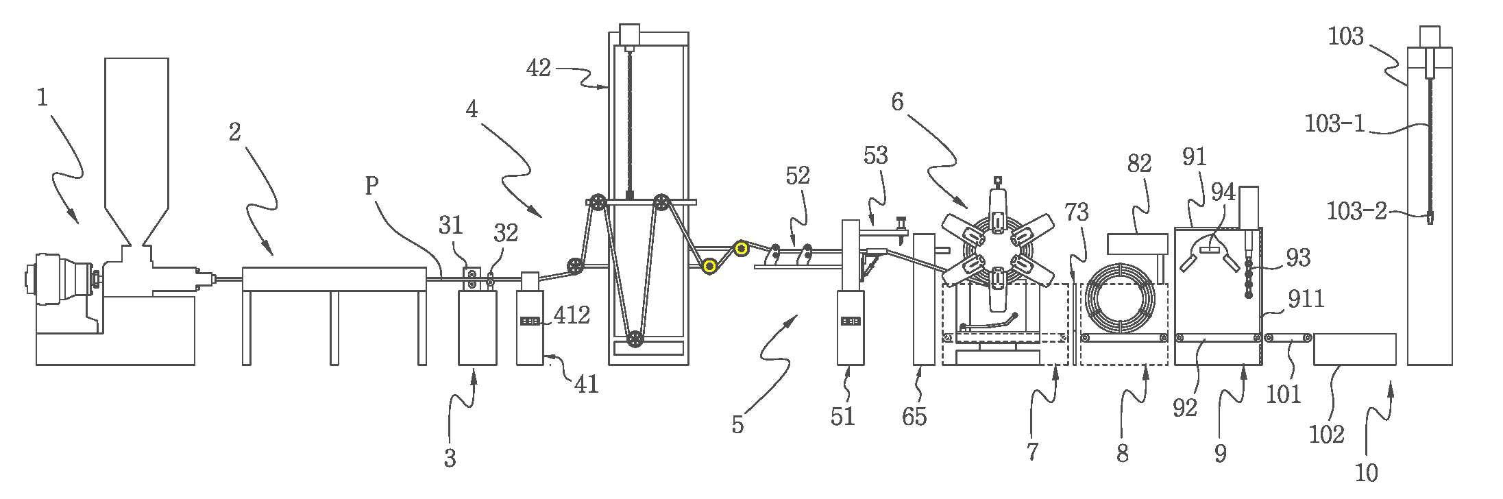
도 1은 본 발명에 따른 콤바인 덕트관 무인 자동화 생산시스템의 개략적인 전체 배치구성도
도 2는 본 발명에 적용되는 압출성형기와 냉각처리기의 확대사시도
도 3은 본 발명에 적용되는 인취기와 자동장력조절기와 권취량 자동조절 제어기의 확대사시도
도 4는 본 발명에 적용되는 자동권취기와 자동배출운반기와 자동포장기의 확대사시도
도 5는 본 발명에 적용되는 자동권취기의 작동상태도
도 6은 본 발명에 적용되는 자동권취기의 요부확대 작용상태도
도 7은 본 발명에 적용되는 자동포장기의 확대 작용상태도
도 8은 본 발명에 적용되는 자동포장수축기의 확대 작용상태도1 is a schematic overall arrangement diagram of an unmanned automated production system for a combine duct pipe according to the present invention;
2 is an enlarged perspective view of an extruder and a cooling processor applied to the present invention;
3 is an enlarged perspective view of a take-up machine, an automatic tension controller, and a winding amount automatic adjustment controller applied to the present invention;
4 is an enlarged perspective view of an automatic winder, an automatic discharge transporter, and an automatic packaging machine applied to the present invention;
5 is an operation state diagram of an automatic winder applied to the present invention;
6 is an enlarged operation state diagram of the automatic winding machine applied to the present invention;
7 is an enlarged operational state diagram of an automatic packaging machine applied to the present invention;
8 is an enlarged operational state diagram of the automatic packaging retractor applied to the present invention;
이하 본 발명에 따른 콤바인 덕트관 무인 자동화 생산시스템의 바람직한 실시예 구성을 첨부도면에 의거하여 상세히 설명하기로 한다. Hereinafter, the configuration of a preferred embodiment of the unmanned automated combine duct pipe production system according to the present invention will be described in detail based on the accompanying drawings.
첨부도면을 참고로하여 본 발명에 따른 콤바인 덕트관 무인 자동화 생산시스템의 개략적인 구성을 살펴보면;Looking at the schematic configuration of the unmanned automated production system of the combine duct pipe according to the present invention with reference to the accompanying drawings;
이는, 도 1로 도시된 바와 같이, 압출성형기(1)와, 냉각처리기(2)와, 인취기(3)와, 자동장력조절기(4)와, 권취량 자동조절 제어기(5)와, 자동권취기(6)와, 자동배출운반기(7)와, 자동포장기(8)와, 자동포장수축기(9)와, 자동운반적재기(10)로 구성된다.This is, as shown in FIG. 1, an extruder (1), a cooling processor (2), a take-up machine (3), an automatic tension controller (4), an automatic winding amount automatic adjustment controller (5), and an automatic It consists of a winding machine (6), an automatic discharging machine (7), an automatic packaging machine (8), an automatic packaging shrinking machine (9), and an automatic transportation and loading machine (10).
여기서, 먼저, 상기 압출성형기(1)는, 합성수지 원료를 고온으로 용융하고, 용융된 합성수지 원료를 금형을 통해 압출가공하여 콤바인 덕트관(P)을 연속적으로 성형 공급하는 수단인바, 이러한 압출성형기(1)는 파이프, 전선피복 등 다양한 플라스틱 제품을 성형하는데 이용하는 통상의 압출성형기(1)를 본 발명에 그대로 적용시켜 이용함이 바람직한 것으로, 그에 대한 세부적인 구성 및 기능 설명은 생략하기로 한다. Here, first, the
또한, 상기 냉각처리기(2)는, 전술한 압출성형기(1)를 통해 성형 공급되는 콤바인 덕트관(P)을 연속적 흐름방식으로 유도하며 냉각처리하는 수단인바, 이와 같은, 냉각처리기(2)는 도 1 또는 도 2 로 도시된 바와 같이, 소정의 길이를 갖으며 상부면이 개방된 냉각수조(21)를 형성하고, 상기 냉각수조(21) 내측면에 규칙적인 다수개의 간격 배열구성으로 냉유도로울러(22)를 설치하며, 재차, 상기 냉각유도로울러(22)가 설치된 냉각수조(21)에 냉각수(23)를 충진하여 형성한 것으로, 이는 통상의 콤바인 덕트관 제조장치에 사용되는 냉각처리기와 상이함이 없는 동일 기능 및 구성을 갖고, 본 발명은 이러한 통상의 냉각처리기를 그대로 적용함이 바람직하다.In addition, the
또한, 상기 인취기(3)는, 전술한 냉각처리기(2)를 통해 냉각처리된 콤바인 덕트관(P1)을 연속적으로 유도 인출하여 후술하는 자동장력조절기(4)로 흐름 전달하기 위한 수단인바, 이와 같은, 인취기(3)는 도 1 또는 도 3으로 도시된 바와 같이, 상부면 에 회전 마찰압력을 이용하여 전술한 냉각처리기(2)로부터 콤바인 덕트관(P)의 인출을 유도하는 인출로울러유닛(31)과, 상기 인출로울러유닛(31)에 의해 인출 전달되는 콤바인 덕트관(P)을 안정적으로 받침하여 흐름 유도하는 인출롤링가이드(32)를 일렬 배치구성으로 이격 설치하여 형성함이 바람직하다. In addition, the take-off device (3) is a means for continuously inducing and withdrawing the combined duct pipe (P1) cooled through the cooling processor (2) described above and delivering the flow to the automatic tension controller (4) to be described later. As shown in FIG. 1 or 3, the take-
또한, 상기 자동장력조절기(4)는, 전술한 인취기(3)로부터 유도 인출되는 콤바인 덕트관(P)을 연속적으로 흐름 유도하며 콤바인 덕트관(P)의 권취장력을 조절하기 위한 수단인바, 이와 같은 자동장력조절기(4)는 도 1 또는 도 3으로 도시된 바와 같이 콤바인 덕트관(P)의 장력을 실시간 모니터링하는 장력감지유닛(41)을 형성하고, 상기 장력감지유닛(41)과 소정간격 이격된 일렬 배치구성, 예컨대, 상기 모니터링되는 콤바인 덕트관(P)의 장력을 일관되게 조절 유지되게 함과 동시에 장력이 조절된 콤바인 덕트관(P)을 후술하는 권취량 자동조절제어기(5)로 흐름 전달하는 장력조절유닛(42)으로 형성함이 바람직하다.In addition, the automatic tension controller (4) is a means for continuously inducing the flow of the combine duct pipe (P) induced and drawn out from the above-mentioned take-up machine (3) and adjusting the winding tension of the combine duct pipe (P), Such an
이때, 전술한 자동장력조절기(4)에 있어, 상기 장력감지유닛(41)은, 상부면에 장력감지센서(도시생략)가 내장된 장력감지공(411)을 형성하고. 하부면 전방에 감지된 콤바인 덕트관(P)의 장력을 디지털 수치로 표시하는 장력정보모니터(412)를 더 형성한다.At this time, in the
아울러, 전술한 자동장력조절기(4)에 있어, 상기 장력조절유닛(42)은, 도 3으로 도시된 바와 같이 일측면에 유입안내휠(W1)과 타측면에 배출안내휠(W2)과 하부면에 중심안내휠(W3)과 상단부에 견인모터(M1)가 고정 설치된 직사각 틀체 구성의 기초 설치프레임(421)을 직립 설치구조로 형성하고, 상기 기초 설치프레임(421) 전방면에 좌,우 한쌍의 승강유도휠(W4)이 이격 설치된 가변프레임(422)을 레일(R)에 의한 결합구조로 수평 설치하며, 재차 상기 가변프레임(422)을 상기 견인모터(M1)에 의한 체인(C)연결에 의해 승강 구동되도록 형성한다.In addition, in the
또한, 상기 권취량 자동조절제어기(5)는, 전술한 자동장력조절기(4)를 통해 권취장력이 조절된 콤바인 덕트관(P)을 연속적으로 흐름 유도하고, 흐름 유도되는 콤바인 덕트관(P)의 권취량, 예컨대, 권취길이 길이를 셋팅 입력된 설정수치 맞추어 자동 감지하여 절단 처리하는 수단인바, 이와 같은, 권취량 자동조절제어기(5)는, 도 1 또는 도 3으로 도시된 바와 같이, 직사각 기둥구조로 직립 설치된 고정컬럼(51)을 형성하고, 상기 고정컬럼(51) 일측면에 전술한 자동장력조절기(4)로부터 전달되는 콤바인 덕트관(P)을 흐름 유도하는 덕트관 유도유닛(52)을 돌출 연장구조로 형성하며, 상기 고정컬럼(51) 타측면에 덕트관 유도유닛(52)으로부터 콤바인 덕트관(P)을 흐름 전달받아 후술하는 자동권취기(6)로 공급하는 권취조절유닛(53)으로 형성함이 바람직하다.In addition, the winding amount
이때, 전술한 권취량 자동조절제어기(5)에 있어, 상기 덕트관 유도유닛(52)은, 도 3으로 도시된 바와 같이, 수평구조로 돌출 연장된 받침편(521)을 형성하고. 상기 받침편(521) 상부면에 수평 배열구조를 이루며 이격 설치된 한쌍의 이송유도로울러(522)로 형성한다.At this time, in the aforementioned automatic winding
아울러, 전술한 권취량 자동조절제어기(5)에 있어, 상기 권취조절유닛(53)은, 수평구조로 연장하는 설치지지보(531-1) 단부에 컷팅구동실린더(531-2)와 컷팅날(531-3)을 장착한 덕트관 절단기(531)를 형성하고, 상기 덕트관 절단기(531) 하부면에 고정브라켓(532-1)에 의해 수평 연장구조로 설치된 덕트관 유도공급파이프(532)로 형성한다. In addition, in the above-described winding amount
또 다르게, 전술한 권취량 자동조절제어기(5)에 있어, 상기 고정컬럼(51)은 상부면에 상기 덕트관 유도유닛(52)으로 형성된 이송유도로울러(522)와, 상기 권취조절유닛(53)으로 형성된 덕트관 유도공급파이프(532)의 설치부위를 수평으로 관통 연결하며 그 관통된 내경부에 길이측정 감지센서(도시생략)를 내장한 덕트관 안내공(511)을 형성하고, 고정컬럼(51) 하부면 전방에 길이측정 감지센서(도시생략)에 의해 측정된 콤바인 덕트관(P)의 흐름 전달길이를 디지털 수치로 표시하는 공급길이 정보모니터(512)를 더 형성한다.Alternatively, in the aforementioned automatic winding amount
또한, 상기 자동권취기(6)는, 전술한 권취량 자동조절제어기(5)를 통해 셋팅된 권취길이로 절단되는 콤바인 덕트관(P)을 권취하고, 권취된 콤바인 덕트관(P)을 밴딩처리하여 도 5로 도시된 바와 같은 형상과 모양의 묶음덕트관(P1)을 가공 형성하는 구성인바, 이와 같은, 자동권취기(6)는, 도 1 또는 도 4로 도시된 바와 같이 받침유닛(61)을 기초 구성으로 하여, 상기 받침유닛(61) 상부면 중앙에 직립구조로 설치되며 정역방향으로 회전제어되는 구동컬럼(62)을 형성하고, 상기 구동컬럼(62) 상부중앙 좌,우 양측면에 대칭구조로 고정 설치되는 한쌍의 권취유닛(63)을 형성하며, 상기 구동컬럼(62) 상단부 좌,우 양측면에 대칭구조로 설치되는 한쌍의 배출유도유닛(64)을 형성하고, 재차, 상기 받침유닛(61)의 좌측 일측면에 도 4로 도시된 바와 같이 소정 간격 이격 배치된 구성으로 밴딩유닛(65)을 설치 형성함이 바람직하다.In addition, the automatic winding
이때, 전술한 자동권취기(6)에 있어, 상기 받침유닛(61)은, 도 4로 도시된 바와 같이, 하부고정판(611)을 형성하고, 상기 하부고정판(611) 상부면 중앙에 회전제어모터(M2)를 설치 형성하며, 재차 회전제어모터(M2) 상부면에 상기 하부고정판(611)과 대칭 이격된 구조를 취하며 회전제어모터(M2)에 의해 정역방향으로 회전 작동하는 상부회동판(612)을 설치 형성하고, 상기 형성된 상부회동판(612)의 좌측 상부면에 구동모터(도시생략)에 의해 회동 작동하는 풀림방지로드(613)를 더 형성한다.At this time, in the automatic winding
아울러, 전술한 자동권취기(6)에 있어, 상기 한쌍의 권취유닛(63)은, 도 4 내지 도 6으로 도시된 바와 같이 다수개로 분할된 원형 배치구성의 고정지지편(631)과, 다수개로 분할된 원형 배치구성의 회동지지편(632)을 형성하고, 상기 고정지지편(631)과 회동지지편(632)을 서로 마주보는 구조, 예컨대, 소정간격 이격된 대향구조로 연결하는 권취지지편(633)으로 형성하며, 재차 상기 권취지지편(633) 내측면에 회동지지편(632)의 개폐를 단속하는 링크형 구동실린더(634)를 더 설치형성하고, 상기 회동지지편(632)이 개폐되며 접하는 권취지지편(633)의 외측 일면 도 로 도시된 바와 같은 덕트관 압입고정홈(H)을 더 형성한다.In addition, in the above-described automatic winding
또 다르게, 전술한 자동권취기(6)에 있어, 상기 한쌍의 배출유도유닛(64)은, 도 4 또는 5로 도시된 바와 같이, 설치고정대(641)를 형성하고, 상기 설치고정대(641) 일측면에 수평구조로 고정설치되는 이송제어실린더(642)를 형성하며, 재차 상기 이송제어실린더(642) 구동에 의해 수평 이송작용을 행하는 이송안내로드(643)를 형성하되, 상기 이송안내로드(643)는 일측단부에 접촉밀대(643-1)를 더 연결 형성한다.Alternatively, in the
또한, 상기 자동배출운반기(7)는, 전술한 자동권취기(6)를 통해 권취됨과 동시에 밴딩처리된 묶음덕트관(P1)을 낙하 받침구조로 전달받고, 전달받은 묶음덕트관(P1)을 연속하여 후술하는 자동포장기(8)로 전달 공급하는 수단인바, 이와 같은 자동배출운반기(7)는 도 4 또는 도 5로 도시된 바와 같이 밴딩처리된 묶음덕트관(P1)을 구동모터(도시생략) 제어에 의해 회전 리프트방식으로 받침 운반하는 회동받침편(71)을 형성하고, 상기 회동받침편(71)에 의해 묶음덕트관(P1)을 전달받고, 전달받은 묶음덕트관(P1)을 후술하는 자동포장기(8)로 이송 운반하는 이탈방지휀스(721)가 설치된 운반컨베이어(72)를 형성하며, 재차 상기 운반컨베이어(72) 전방 일측면에 이격 배치구조로 설치되며 이송되는 묶음덕트관(P1)의 운반간격을 조절하는 운반간격 조절유닛(73)으로 형성하되, 상기 운반간격 조절유닛(73)은 전,후 슬라딩 방식으로 개폐동작하는 격리판(731)을 더 형성한다.In addition, the automatic discharge carrier (7) receives the bundled duct pipe (P1) that is wound through the above-described automatic winder (6) and at the same time bending is delivered to the drop support structure, and the delivered bundled duct pipe (P1) It is a means of continuously delivering and supplying to the
또한, 상기 자동포장기(8)는, 전술한 자동배출운반기(7)로부터 묶음덕트관(P1)을 연속 흐름방식으로 전달받고, 전달받은 묶음덕트관(P1)의 외관둘레를 필름지(V)에 의해 2차 형태로 압박고정하여 포장하는 수단인바, 이와 같은 자동포장기(8)는, 도 7로 도시된 바와 같이, 일렬 배치구조로 연결된 포장유입안내 컨베이어(81)와, 히팅포장유닛(82)과, 포장배출안내 컨베이어(83)로 형성함이 바람직하다.In addition, the
이때, 전술한 자동포장기(8)에 있어 상기 히팅포장유닛(82)은 도 7로 도시된 바와 같이, 상부 컷팅겸용융착기(821)와 하부 컷팅겸용융착기(822)가 상,하 이격 배치된 수직 대향구조로 형성되는 것을 포함한다.At this time, in the above-described
더 나아가, 상기 상부 컷팅겸용융착기(821)는, 전방면으로 고정설치되는 포장필름공급기(821-1) 및 상기 포장필름공급기(821-1) 후면에 근접 설치되어 승강 작동하는 구성으로, 도 7로 도시된 바와 같이 밀착유도편(G)과 고온의 발열작용을 행하는 히팅컷팅편(B))을 전,후 이격구성으로 배치한 포장필름절단기(821-2)로 형성하고;Furthermore, the upper cutting and
상기 하부 컷팅겸용융착기(822)는, 전방면으로 고정설치되는 보조 포장필름공급기(822-1) 및 상기 보조 포장필름공급기(822-1) 후면에 근접 설치되어 승강 작동하는 구성으로, 도 7로 도시된 바와 같이 보조 밀착유도편(G1)과 고온의 발열작용을 행하는 보조 히팅컷팅편(B1))을 전,후 이격구성으로 배치한 포조 포장필름절단기(822-2)로 형성한다.The lower cutting and
아울러, 전술한 자동포장기(8)에 있어, 상기 포장필름절단기(821-2)와 보조 포장필름절단기(822-2)를 구동실린더 등의 동력수단에 의해 상하 대향구조로 승강작동시켜 히팅컷팅편(B)과 보조 히팅컷팅편(B1)이 밀착 접촉되게하고, 상기 히팅컷팅편(B)과 보조 히팅컷팅편(B1)의 밀착 접촉에 따른 히팅 용융작용에 의해 필름지(V)를 절단함과 동시에 그 필름지(V)의 절단면을 히팅컷팅편(B)과 보조 히팅컷팅편(B1)의 용용 밀착작용에 의해 도 7로 도시된 바와 같이 부착 고정되도록 형성한다.In addition, in the above-described
또한, 상기 자동포장수축기(9)는, 전술한 자동포장기(8)를 통해 필름지가 압박 포장된 묶음덕트관(P1)을 연속 흐름방식으로 전달받고, 전달받은 묶음덕트관(P1)의 외관둘레에 열풍을 가하여 고온 수축작용에 필름지를 밀착구조로 압박고정하는 수단인바, 이와 같은 자동포장수축기(9)는, 도 1 또는 도 9로 도시된 바와 같이 밀폐구조를 취하며 전방면에 포장완료 배출도어(911)를 형성한 직사삭 케이스 형태의 열풍가공부스(91)를 형성하고, 상기 열풍가공부스(91) 내측 하부면에 필름지가 포장된 묶음덕트관(P1)이 공회전되도록 유도하는 공회전 유도컨베이어(92)를 형성하며, 상기 공회전 유도컨베이어(92)와 접하는 열풍가공부스(91) 내측 전방에 구동실린더 등의 동력수단에 의해 승강작동하는 설치구성, 예컨대, 도 8로 도시된 바와 같이 공회전 유도로울러(93)를 형성하고, 상기 공회전 유도컨베이어(92) 상부측과 좌,우 양측면에 다수개의 분할 배치구조로 이격 설치되는 열풍분사관(94)을 형성함이 바람직하다. In addition, the
끝으로, 상기 자동운반적재기(10)는, 전술한 자동포장수축기(9)에 의한 고온 수축작용에 의해 필름지가 압박포장된 묶음덕트관(P1)을 연속흐름방식으로 전달받고, 전달받은 묶음덕트관(P1)을 호이스트 방식으로 운반 적재하는 수단인바, 이와 같은 자동운반적재기(10)는, 도 1로 도시된 바와 같이 필름지(V)가 압박포장된 묶음덕트관(P1)을 이송 운반하는 최종 배출컨베이어(101)를 형성하고, 상기 최종 배출컨베이어(101) 전방면에 운반된 묶음덕트관(P1)을 적재 대기상태로 받침 고정하는 수거받침테이블(102)을 연결 형성하며, 재차 상기 수거받침테이블(102) 전방면에 적재체인(103-1)과 확장형 유압집게(103-2)가 연결된 호이스트 적재유닛(103)을 이격 배치구성으로 더 설치 형성함이 바람직하다.Finally, the automatic transport and
따라서, 전술한 일련의 구성으로 이루어진 본 발명에 따른 콤바인 덕트관 무인 자동화 생산시스템의 유기적인 흐름 작동관계와 그에 따른 상호 작용을 살펴보면 다음과 같다.Therefore, looking at the organic flow operation relationship and the interaction thereof of the unmanned automated combine duct tube production system according to the present invention consisting of the above-described series of configurations are as follows.
먼저, 합성수지 원료를 압출성형기(1)에 투입하여, 고온의 용융작용과 금형 에 의한 압출가공을 통해 콤바인 덕트관(P)을 성형하고, 성형된 콤바인 덕트관(P)을 냉각처리기(2)로 전달하여 냉각수조(21)에 충진된 냉각수(23)에 침지시키는 방식으로 냉각 처리하며, 재차 상기 냉각처리된 콤바인 덕트관(P)을 인취기(3)에 의해 인출 유도하여 자동장력조절기(4)로 전달한다. First, the synthetic resin raw material is put into the extrusion molding machine (1), and the combine duct pipe (P) is molded through the high-temperature melting action and extrusion processing by the mold, and the molded combine duct pipe (P) is cooled to the cooling processor (2) The cooling process is carried out in such a way that it is transferred to the cooling
다음 과정으로 상기 자동조절기(4)는, 인취기로(3)로 부터 전달받은 콤바인 덕트관(P)의 흐름 장력수치를 장력감지유닛(41)에 의해 실시간 모티터링하고, 모티터링 되는 장력 수치정보에 따라 장력조절유닛(42)으로 형성된 가변프레임(422)을 견인모터(M1)와 체인구동(C)에 의해 승강구동시켜 콤바인 덕트관(P)의 장력이 변동없이 일정하게 유지되도록 조절하며, 그와 같이 일정하게 유지되는 장력으로 콤바인 덕트관(P)을 권취량 자동조절제어기(5)로 전달한다.In the following process, the
다음 과정으로 상기 권취량 자동조절제어기(5)는 자동장력조절기(4)로부터 전달되는 콤바인 덕트관(P)을 덕트관 유도유닛 (52)과 권취조절유닛(53)을 통해 권취조절유닛(53)으로 전달하되, 그 전달되는 콤바인 덕트관(P)의 권취용량, 예컨대, 콤바인 덕트관(P)의 권취길이를 덕트관 안내공(511)에 내장된 길이측정 감지센서(도시생략)에 의해 체크하여 공급길이 정보모니터(512)를 통해 수치 정보로 표시하고, 아울러, 그러한 정보표시와 함께 프로그램 입력에 의해 미리 셋팅해 놓은 수치, 예컨대, 권취용량(길이)에 맞추어 콤바인 덕트관(P)을 덕트관 절단기(531)에 의해 절단하며, 권취용량(길이) 만큼 절단된 콤바인 덕트관(P)은 자동권취기(6)로 전달한다.In the following process, the winding amount
다음과정으로 상기 자동권취기(6)는, 자동조절제어기(5)를 통해 셋팅된 권취길이로 절단되는 콤바인 덕트관(P)을 한쌍의 권취유닛(63)중 좌측에 위치한 권취유닛(63)에 권취하고, 상기 권취된 콤바인 덕트관(P)의 절단된 끝단부를 풀림방지로드(613)의 회동 밀착작용에 의해 고정하며, 그와 같이, 콤바인 덕트관(P)이 권취 고정된 좌측 권취유닛(63)을 구동컬럼(62)의 회동작용에 의해 우측 방향으로 위치 이동시켜 밴딩유닛(65)에 의해 권취된 콤바인 덕트관(P)을 밴딩처리하여 묽음덕트관(P1)을 형성한다.In the following process, the automatic winding
여기서, 상기 밴딩처리가 이루어지는 과정에 있어, 구동컬럼(62) 회동작용에 의해 좌측 권취유닛(63)과 위치가 변경된 우측 권취유닛(63)으로는 앞서 위치가 변경되기 전의 좌측 권추유닛(63)과 동일하게 셋팅된 권취길이로 절단된 콤바인 덕트관(P)이 권취되며, 이러한 절단된 콤바인 덕트관(P)의 연속적인 권취작용은 도 6으 로 도시된 바와 같이, 콤바인 덕트관(P)의 절단된 단부가 덕트관 삽입고정홈(H)으로 연장 삽입되면 물림되는 구조에 의해 이루어진다. Here, in the process of performing the bending process, the
이어, 상기와 같이 위치가 변경된 형태로, 밴딩처리와 함께 콤바인 덕트관(P)의 권취가 동시에 이루어진 좌측과 우측 한쌍의 권취유닛(63)을 구동컬럼(62) 회동작용에 의해 다시한번 회전시켜 그들 한쌍의 권취유닛(63)의 위치를 변경시키고, 그와 같이 권취유닛(63)의 위치가 변경된 상태하에 밴딩처리된 묽음덕트관(P1)은 회동지지편(632)의 개방과 함께 이송안내로드(643)의 접촉밀대(643-1)에 의해 밀어내어 자동배출 운반기(7)로 낙하 전달하고, 새롭게 권취된 콤바인 덕트관(P)은 밴딩유닛(65)에 의해 묶음덕트관(P1)으로 밴딩처리한다. Next, in the form in which the position is changed as described above, the left and right pair of winding
다음 과정으로 상기 자동배출 운반기(7)는, 상기 자동권취기(6)를 통해 낙하 전달받은 묶음덕트관(P1)을 회동받침편(7)과 운반컨베이어(72)를 통해 자동포장기(8)로 흐름 전달하되, 그 전달 과정에 있어 격리판(731)에 의한 차단 개폐작용에 의해 묶음덕트관(P1)의 운반간격을 조절하여 자동포장기(8)를 통해 진행되는 포장작업에 간섭을 주지 않도록 한다.In the following process, the
다음 과정으로 상기 자동포장기(8)는, 상기 자동배출 운반기(7)를 통해 전달되는 묶음덕트관(P1) 외관둘레를 히팅포장유닛(82)에 의해 도 7로 도시된 바와 같이 가결합 형태로 필름지를 포장하고, 상기 가결합 형태로 필름지가 포장된 묶음덕트관(P1)을 자동포장수축기(9)로 전달한다.In the next process, the
다음 과정으로, 상기 자동포장수축기(9)는, 자동포장기(8)로부터 전달받은 묶음덕트관(P1)의 외관둘레, 예컨대, 가결합 포장상태를 취하는 필름지에 열풍을 가하여, 그 가결합 상태의 필름지를 열수축작용에 의해 다시 한번 압박 고정하고, 상기 열수축 작용에 의해 필름지가 압박 고정된 묶음덕트관(P1)을 자동운반적재기(10)로 전달하여 수거받침테이블(102)과 호이스트 적재유닛(103)에 의한 운반작용에 의해 묶음덕트관(P1)을 별도 마련된 파렛트(도시생략), 예컨대, 지게차 등에 의해 운반되는 물품받침대에 적재함으로써, 본 발명에 따른 콤바인 덕트관 무인 자동화 생산시스템을 구현한다.In the next process, the
1 : 압출성형기 2 : 냉각처리기
3 : 인취기 4 : 자동장력조절기
5 : 권취량 자동조절제어기 6 : 자동권취기
7 : 자동배출 운반기 8 : 자동포장기
9 : 자동포장 수축기 10 : 자동운반 적재기
21 : 냉각수조 22 : 냉각유도 로울러
41 : 장력감지유닛 42 : 장력조절유닛
51 : 고정컬럼 52 : 덕트관 유도유닛
53 : 권취조절유닛 61 : 받침유닛
62 : 구동컬럼 63 : 권취유닛
64 : 배출유도유닛 65 : 밴딩유닛
71 : 회동받침편 72 : 운반컨베이어
73 : 운반간격 조절유닛 81 : 포장유입안내 컨베이어
82 : 히팅포장유닛 83 : 포장배출안내 컨베이어
91 : 열풍가공부스 92 : 공회전 유도컨베이어
93 : 공회전 유도로울러 94 : 열풍분사관
101 : 최종배출 컨베이어 102 : 수거받침테이블
103 : 호이스트 적재유닛1: Extruder 2: Cooling machine
3: Take-off device 4: Automatic tension controller
5: winding amount automatic adjustment controller 6: automatic winding machine
7: automatic discharge transporter 8: automatic packaging machine
9: Automatic packaging shrinker 10: Automatic transport and loading machine
21: cooling water tank 22: cooling induction roller
41: tension sensing unit 42: tension adjusting unit
51: fixed column 52: duct pipe induction unit
53: winding control unit 61: support unit
62: driving column 63: winding unit
64: discharge induction unit 65: bending unit
71: rotating support piece 72: transport conveyor
73: transport interval control unit 81: package inflow guide conveyor
82: heating packaging unit 83: packaging discharge guide conveyor
91: hot air processing booth 92: idling induction conveyor
93: idling induction roller 94: hot air injection pipe
101: final discharge conveyor 102: collection support table
103: hoist loading unit
Claims (8)
상기 성형공급되는 콤바인 덕트관(P)을 연속으로 흐름 유도하며 냉각수 침지방식에 의해 냉각처리하는 냉각처리기(2)와;
상기 냉각된 콤바인 덕트관(P)을 유도 인출하는 인취기(3)와;
상기 인취기(3)로부터 유도 인출되는 콤바인 덕트관(P)을 연속적으로 흐름유도하며 콤바인 덕트관(P)의 권취장력을 조절하는 자동장력조절기(4)와;
상기 권취장력이 조절된 콤바인 덕트관(P)을 연속적으로 흐름 유도하고, 흐름 유도되는 콤바인 덕트관(P)의 권취길이를 셋팅 입력된 설정수치 맞추어 자동 감지하여 절단 처리하는 권취량 자동조절제어기(5)와;
상기 셋팅된 권취길이에 맞추어 절단되는 콤바인 덕트관(P)을 권취하고, 권취된 콤바인 덕트관을(P) 밴딩처리하여 묶음덕트관(P1)을 형성하는 자동권취기(6)와;
상기 권취후 밴딩처리된 묶음덕트관(P1)을 권취기(6)로부터 낙하 받침구조로 전달받는 자동배출운반기(7)와;
상기 자동배출운반기(7)로부터 묶음덕트관(P1)을 연속 흐름방식으로 전달받고, 전달받은 묶음덕트관(P1)의 외관둘레를 필름지에 의해 압박 포장하는 자동포장기(8)와;
상기 필름지에 의해 포장된 묶음덕트관(P1)을 연속 흐름방식으로 전달받고, 묶음덕트관(P1)의 외관둘레에 열풍을 가하여 고온 수축작용에 필름지를 밀착구조로 압박고정하는 자동포장수축기(9)와;
상기 고온 수축작용에 의해 필름지가 압박고정된 묶음덕트관(P1)을 연속흐름방식으로 전달받고, 전달받은 묶음덕트관(P1)을 호이스트 방식으로 운반 적재하는 자동운반적재기(10)를 포함하는 콤바인 덕트관 무인 자동화 생산시스템을 구성하되;
상기 자동장력조절기(4)는, 콤바인 덕트관(P)의 장력을 실시간 모니터링하는 장력감지유닛(41)과, 모니터링되는 콤바인 덕트관(P)의 장력이 일관되게 유지되도록 조절하며 그 콤바인 덕트관(P)을 권취량 자동조절제어기(5)로 흐름 전달하는 장력조절유닛(42)으로 형성되는 것을 포함하고;
상기 장력감지유닛(41)은, 상부면에 장력감지센서가 내장된 장력감지공(411)과. 하부면에 감지된 콤바인 덕트관(P)의 장력을 디지털 수치로 표시하는 장력정보모니터(412)를 형성하며;
상기 장력조절유닛(42), 일측면에 유입안내휠(W1)과, 타측면에 배출안내휠(W2)과, 하부면에 중심안내휠(W3)과, 상단부에 견인모터(M1)가 고정 설치된 기초 설치프레임(421)을 형성하고, 상기 기초 설치프레임(421) 전방면에 한쌍의 승강유도휠(W4)이 이격 설치된 가변프레임(422)을 레일결합구조로 형성하며, 상기 가변프레임(422)을 견인모터(M1)에 의한 체인(C)연결에 의해 승강 구동시키는 구성으로 형성함을 특징으로 하는 콤바인 덕트관 무인 자동화 생산시스템.
An extruder (1) for molding and supplying the combine duct pipe (P);
a cooling processor (2) for continuously guiding the combined duct pipe (P) to be molded and supplied and cooling it by a cooling water immersion method;
And a take-off device (3) for inductively withdrawing the cooled combine duct pipe (P);
An automatic tension regulator (4) for continuously inducing the flow of the combine duct pipe (P) withdrawn from the take-up machine (3) and adjusting the winding tension of the combine duct pipe (P);
A winding amount automatic adjustment controller ( 5) and;
An automatic winder (6) for winding the combine duct pipe (P) cut according to the set winding length, and bending the wound combine duct pipe (P) to form a bundled duct pipe (P1);
An automatic discharge carrier (7) for receiving the bundled duct pipe (P1), which is bent after winding, from the winder (6) to the drop support structure;
An automatic packaging machine (8) for receiving the bundled duct pipe (P1) from the automatic discharge carrier (7) in a continuous flow manner, and compressing and packaging the outer circumference of the delivered bundled duct pipe (P1) with film paper;
An automatic packaging shrinker (9) that receives the bundled duct pipe (P1) wrapped by the film paper in a continuous flow method, and applies hot air to the outer circumference of the bundled duct pipe (P1) to press and fix the film paper in a close-fitting structure to the high temperature shrinkage action (9) )Wow;
The combined duct pipe (P1) to which the film paper is pressed and fixed by the high-temperature contraction action is delivered in a continuous flow method, and the delivered bundled duct pipe (P1) is transported and loaded in a hoist method. A combine comprising a loader (10) Configure the duct pipe unmanned automated production system;
The automatic tension regulator 4, the tension sensing unit 41 for real-time monitoring the tension of the combine duct pipe (P), and adjusts the tension of the monitored combine duct pipe (P) to be consistently maintained and the combine duct pipe (P) comprising being formed with a tension control unit 42 for flow-transferring to the winding amount automatic adjustment controller 5;
The tension sensing unit 41, and a tension sensing hole 411 having a built-in tension sensor on the upper surface. Forming a tension information monitor 412 for displaying the tension of the sensed combine duct pipe (P) in a digital numerical value on the lower surface;
The tension control unit 42, the inlet guide wheel (W1) on one side, the discharge guide wheel (W2) on the other side, the center guide wheel (W3) on the lower surface, and the traction motor (M1) at the upper end are fixed The installed base installation frame 421 is formed, and the variable frame 422 in which a pair of lift induction wheels W4 are installed spaced apart from the front surface of the foundation installation frame 421 is formed in a rail coupling structure, and the variable frame 422 ) by a chain (C) connection by a traction motor (M1), characterized in that it is formed in a configuration to drive up and down the combine duct tube unmanned automated production system.
권취량 자동조절제어기(5)는, 고정컬럼(51)과, 고정컬럼(51) 일측면에 자동장력조절기(4)로부터 전달되는 콤바인 덕트관(P)을 흐름 유도하는 덕트관 유도유닛(52)과, 고정컬럼(51) 타측면에 덕트관 유도유닛(52)으로부터 콤바인 덕트관(P)을 흐름 전달받아 자동권취기(6)로 공급하는 권취조절유닛(53)으로 형성하되;
상기 덕트관 유도유닛(52)은, 받침편(521)과. 받침편(521) 상부면에 수평 배열구조로 이격 설치된 한쌍의 이송유도로울러(522)로 형성되고;
상기 권취조절유닛(53)은, 수평구조로 연장하는 설치지지보(531-1) 단부에 컷팅구동실린더(531-2)와 컷팅날(531-3)을 장착시킨 덕트관 절단기(531)와, 덕트관 절단기(531) 하부면에 고정브라켓(532-1)에 의해 수평 연장구조로 설치된 덕트관 유도공급파이프(532)로 형성되며;
상기 고정컬럼(51)은 상부면에 덕트관 유도유닛(52)으로 형성된 이송유도로울러(522)와, 권취조절유닛(53)으로 형성된 덕트관 유도공급파이프(532)의 설치부위를 수평으로 관통 연결하며 그 관통된 내경부에 길이측정 감지센서를 내장한 덕트관 안내공(511)을 형성하고, 하부면 전방에 길이측정 감지센서에 의해 측정된 콤바인 덕트관(P)의 흐름 전달길이를 디지털 수치로 표시하는 공급길이 정보모니터(512)로 형성됨을 특징으로 하는 콤바인 덕트관 무인 자동화 생산시스템.The method of claim 1 ;
The winding amount automatic adjustment controller 5 is a fixed column 51 and a duct tube induction unit 52 for guiding the combined duct pipe (P) delivered from the automatic tension controller 4 on one side of the fixed column 51 to flow. ) and the fixed column 51 on the other side of the duct pipe induction unit 52 to receive the flow of the combine duct pipe (P) and form a winding control unit 53 for supplying to the automatic winding machine (6);
The duct pipe guide unit 52, and the support piece (521). It is formed of a pair of transport guide rollers 522 spaced apart from each other in a horizontal arrangement on the upper surface of the support piece 521;
The winding control unit 53 includes a duct pipe cutter 531 in which a cutting driving cylinder 531-2 and a cutting blade 531-3 are mounted at the end of the installation support beam 531-1 extending in a horizontal structure; , is formed of a duct pipe guide supply pipe 532 installed in a horizontally extended structure by a fixing bracket 532-1 on the lower surface of the duct pipe cutter 531;
The fixed column 51 horizontally penetrates the installation site of the transfer guide roller 522 formed of the duct tube induction unit 52 on the upper surface and the duct tube guide supply pipe 532 formed of the winding control unit 53. Connecting and forming a duct pipe guide hole 511 with a built-in length measurement sensor in the inner diameter part, and digitally measuring the flow transmission length of the combine duct pipe (P) measured by the length measurement sensor in front of the lower surface Combined duct pipe unmanned automated production system, characterized in that formed by the supply length information monitor (512) displayed in numerical value.
자동권취기(6)는, 받침유닛(61)과, 받침유닛(61) 상부면 중앙에 직립구조로 설치되며 정역방향으로 회전제어되는 구동컬럼(62)과, 구동컬럼(62) 상부중앙 좌,우 양측면에 대칭구조로 설치되는 한쌍의 권취유닛(63)과, 구동컬럼(62) 상단부 좌,우 양측면에 대칭구조로 설치되는 한쌍의 배출유도유닛(64)과, 받침유닛(61) 좌측 일측면에 이격 배치구조로 설치되는 밴딩유닛(65)으로 형성하되;
상기 받침유닛(61)은, 하부고정판(611)과, 하부고정판(611) 상부면 중앙으로 설치되는 회전제어모터(M2)와, 회전제어모터(M2) 상부면에 하부고정판(611)과 대칭 이격된 구조로 설치되며 회전제어모터(M2)에 의해 정역방향으로 회전 작동하는 상부회동판(612)과, 상부회동판(612) 좌측상부면에 구동모터에 의해 회동하며 권취유닛(63)으로 권취된 콤파인 덕트관(P)의 풀림을 방지하도록 설치된 풀림방지로드(613)로 형성하고;
상기 권취유닛(63)은, 다수개로 분할된 원형 배치구성의 고정지지편(631)과, 다수개로 분할된 원형 배치구성의 회동지지편(632)과, 분할된 고정지지편(631)과 회동지지편(632)을 이격된 대향구조로 연결하는 권취지지편(633)으로 형성된 것을 포함하며, 상기 권취지지편(633) 내측면에 회동지지편(632)의 개폐를 단속하는 링크형 구동실린더(634)를 더 설치형성하고, 회동지지편(632)이 개폐되며 접하는 권취지지편(633)의 외측 일면 덕트관 압입고정홈(H)을 더 형성하며;
상기 배출유도유닛(64)은, 설치고정대(641)와, 설치고정대(641) 일측면에 수평구조로 고정설치되는 이송제어실린더(642)와, 일측단부에 접촉밀대(643-1)가 마련되며 상기 이송제어실린더(642) 구동에 의해 수평 이송작용을 행하는 이송안내로드(643)로 형성됨을 특징으로 하는 콤바인 덕트관 무인 자동화 생산시스템.
The method of claim 1 ;
The automatic winding machine 6 includes a support unit 61, a drive column 62 installed in an upright structure in the center of the upper surface of the support unit 61 and rotationally controlled in a forward and reverse direction, and a drive column 62 upper center left. , A pair of winding units 63 installed in a symmetrical structure on both sides of the right side, a pair of exhaust induction units 64 installed in a symmetrical structure on both sides of the left and right sides of the upper end of the driving column 62, and the support unit 61 on the left It is formed with a bending unit 65 installed on one side in a spaced arrangement structure;
The support unit 61 is symmetrical with the lower fixed plate 611, the lower fixed plate 611, the rotation control motor M2 installed in the center of the upper surface, and the lower fixed plate 611 on the upper surface of the rotation control motor M2. The upper rotating plate 612 is installed in a spaced apart structure and rotated in the forward and reverse directions by the rotation control motor M2, and the upper rotating plate 612 is rotated by a driving motor on the upper left side of the winding unit 63. Formed with an anti-loosening rod 613 installed to prevent loosening of the wound compact duct pipe (P);
The winding unit 63 is rotated with a fixed support piece 631 of a circular arrangement divided into multiple pieces, a rotation support piece 632 of a circular arrangement divided into multiple pieces, and a fixed support piece 631 divided into multiple pieces. A link-type driving cylinder for intermittent opening and closing of the rotation support piece 632 on the inner surface of the winding support piece 633, including one formed of a winding support piece 633 that connects the support piece 632 in a spaced-apart opposed structure. (634) is further installed, and the rotational support piece (632) is opened and closed and further forms a duct pipe press-fitting fixing groove (H) on the outer side of the winding support piece (633) in contact;
The discharge induction unit 64 is provided with an installation fixture 641, a transfer control cylinder 642 fixedly installed on one side of the installation fixture 641 in a horizontal structure, and a contact pusher 643-1 at one end. and combine duct pipe unmanned automated production system, characterized in that it is formed of a transfer guide rod (643) that performs a horizontal transfer action by driving the transfer control cylinder (642).
자동배출운반기(7)는, 밴딩처리된 묶음덕트관(P1)을 구동모터 제어에 의해 회전 리프트방식으로 받침 운반하는 회동받침편(71)과;
상기 회동받침편(71)에 의해 묶음덕트관(P1)을 전달받고, 전달받은 묶음덕트관(P1)을 자동포장기(8)로 이송 운반하는 이탈방지휀스(721)가 설치된 운반컨베이어(72)와;
상기 운반컨베이어(72) 전방 일측면에 이격 배치구조로 설치되며, 전,후 슬라딩 방식으로 개폐동작하는 격리판(731)에 의해 이송되는 묶음덕트관(P1)의 운반간격을 조절하는 운반간격 조절유닛(73)으로 형성됨을 특징으로 하는 콤바인 덕트관 무인 자동화 생산시스템.
The method of claim 1 ;
The automatic discharge transporter 7 includes: a pivoting support piece 71 for carrying the banded bundled duct pipe P1 in a rotational lift manner under the control of a driving motor;
Received bundled duct pipe (P1) by the rotating support piece (71), and a transport conveyor (72) installed with a separation prevention fence (721) for transporting and transporting the received bundled duct pipe (P1) to the automatic packing machine (8) Wow;
It is installed in a spaced arrangement structure on one side of the front side of the transport conveyor 72, and the transport interval to adjust the transport distance of the bundled duct pipe (P1) transported by the separator 731 that opens and closes in a sliding manner Combine duct tube unmanned automated production system, characterized in that formed by the control unit (73).
자동포장기(8)는, 일렬 배치구조로 연결된 포장유입안내 컨베이어(81)와, 히팅포장유닛(82)과, 포장배출안내 컨베이어(83)로 형성되고;
상기 히팅포장유닛(82)은 상부 컷팅겸용융착기(821)와 하부 컷팅겸용융착기(822)가 상,하 이격 배치된 수직 대향구조로 형성되는 것을 포함하되;
상기 상부 컷팅겸용융착기(821)는, 전방면으로 고정설치되는 포장필름공급기(821-1))와, 밀착유도편(G)과 히팅컷팅편(B))이 전,후 이격구성으로 배치되며 포장필름공급기(821-1) 후면에 근접 설치되어 승강 작동하는 포장필름절단기(821-2)로 형성되고;
상기 하부 컷팅겸용융착기(822)는, 전방면으로 고정설치되는 보조 포장필름공급기(822-1)와, 보조 밀착유도편(G1)과 보조 히팅컷팅편(B1)이 전,후 이격구성으로 배치되며 보조 포장필름공급기(822-1) 후면에 근접 설치되어 승강 작동하는 보조 포장필름절단기(822-2)로 형성되며;
상기 포장필름절단기(821-2)와 보조 포장필름절단기(822-2)가 상하 대향구조로 승강작동하며 히팅컷팅편(B)과 보조 히팅컷팅편(B1)이 밀착 접촉되고, 히팅컷팅편(B)과 보조 히팅컷팅편(B1)의 밀착 접촉에 따른 히팅 용융작용에 의해 필름지(V)가 절단되며, 상기 필름지(V)의 절단과 함께 그 필름지(V)의 절단면을 히팅컷팅편(B)과 보조 히팅컷팅편(B1)의 용용 밀착작용에 의해 부착 고정시키는 것을 특징으로 하는 콤바인 덕트관 무인 자동화 생산시스템.
The method of claim 1 ;
The automatic packaging machine 8 is formed of a package inflow guide conveyor 81 connected in a line arrangement structure, a heating packaging unit 82, and a package discharge guide conveyor 83;
The heating packaging unit 82 includes an upper cutting combined welding machine 821 and a lower cutting combined welding machine 822 formed in a vertically opposed structure in which the upper and lower portions are spaced apart;
The upper cutting and fusion splicer 821 includes a packaging film feeder 821-1 that is fixedly installed on the front side, and an adhesion guide piece (G) and a heating cutting piece (B)) in a front and rear spaced configuration. It is installed close to the rear of the packaging film feeder (821-1) and is formed of a packaging film cutter (821-2) that lifts and lowers;
The lower cutting and fusion splicer 822, the auxiliary packaging film feeder 822-1 fixed to the front side, the auxiliary adhesion guide piece (G1) and the auxiliary heating cutting piece (B1) are arranged in a front and rear spaced configuration and is formed as an auxiliary packaging film cutter (822-2) installed close to the rear of the auxiliary packaging film feeder (822-1) and operating up and down;
The packaging film cutting machine (821-2) and the auxiliary packaging film cutting machine (822-2) operate up and down in an up-and-down opposing structure, and the heating cutting piece (B) and the auxiliary heating cutting piece (B1) are in close contact with each other, and the heating cutting piece ( The film paper (V) is cut by the heating melting action according to the close contact between B) and the auxiliary heating cutting piece (B1), and the cut surface of the film paper (V) is cut along with the cutting of the film paper (V) by the heating cutting piece (B) ) and the auxiliary heating cutting piece (B1), the combined duct tube unmanned automated production system, characterized in that it is attached and fixed by the adhesion action.
자동포장수축기(9)는, 밀폐구조를 취하며 전방면에 포장완료 배출도어(911)를 형성한 열풍가공부스(91)와;
열풍가공부스(91) 내측 하부면에 필름지가 포장된 묶음덕트관(P1)이 공회전되도록 유도하는 공회전 유도컨베이어(92)와;
상기 공회전 유도컨베이어(92)와 접하는 열풍가공부스(91) 내측 전방에 승강작동 구조로 설치되는 공회전 유도로울러(93)와;
상기 공회전 유도컨베이어(92) 상부측과 좌,우 양측면에 다수개의 분할 배치구조로 이격 설치된 열풍분사관(94)으로 형성됨을 특징으로 하는 콤바인 덕트관 무인 자동화 생산시스템.
The method of claim 1 ;
The automatic packaging shrinker 9 includes a hot air processing booth 91 having a closed structure and forming a packaging complete discharge door 911 on the front surface;
An idle rotation induction conveyor 92 for guiding the bundled duct pipe P1 packed with film paper on the inner lower surface of the hot air processing bus 91 to idle;
an idling induction roller 93 installed in a lifting operation structure in front of the hot air processing bus 91 in contact with the idling induction conveyor 92;
Combine duct tube unmanned automated production system, characterized in that it is formed of a plurality of split arrangement structures on the upper side and both sides of the idling induction conveyor (92) and the hot air injection pipe (94) installed spaced apart.
자동운반적재기(10)는, 필름지가 압박포장된 묶음덕트관(P1)을 이송 운반하는 최종 배출컨베이어(101)를 포함하고;
상기 최종 배출컨베이어(101) 전방면에 운반된 묶음덕트관(P1)을 적재 대기상태로 받침 고정하는 수거받침테이블(102)을 연결 형성하며;
상기 수거받침테이블(102) 전방면에 적재체인(103-1)과 확장형 유압집게(103-2)가 연결된 호이스트 적재유닛(103)을 이격 배치구성으로 더 설치 형성함을 특징으로 하는 콤바인 덕트관 무인 자동화 생산시스템.
The method of claim 1 ;
The automatic transport and loader 10 includes a final discharge conveyor 101 for transporting and transporting the bundled duct pipe P1 packed with film paper;
connecting and forming a collection support table 102 for supporting and fixing the bundled duct pipe (P1) transported to the front surface of the final discharge conveyor 101 in a loading standby state;
Combine duct pipe, characterized in that the hoist loading unit 103 connected to the loading chain 103-1 and the extended hydraulic tongs 103-2 on the front surface of the collection support table 102 is further installed in a spaced arrangement configuration Unmanned automated production system.
Priority Applications (1)
| Application Number | Priority Date | Filing Date | Title |
|---|---|---|---|
| KR1020210035952A KR102339552B1 (en) | 2021-03-19 | 2021-03-19 | Combin duct pipe unmanned automated production system |
Applications Claiming Priority (1)
| Application Number | Priority Date | Filing Date | Title |
|---|---|---|---|
| KR1020210035952A KR102339552B1 (en) | 2021-03-19 | 2021-03-19 | Combin duct pipe unmanned automated production system |
Publications (1)
| Publication Number | Publication Date |
|---|---|
| KR102339552B1 true KR102339552B1 (en) | 2021-12-17 |
Family
ID=79033567
Family Applications (1)
| Application Number | Title | Priority Date | Filing Date |
|---|---|---|---|
| KR1020210035952A Expired - Fee Related KR102339552B1 (en) | 2021-03-19 | 2021-03-19 | Combin duct pipe unmanned automated production system |
Country Status (1)
| Country | Link |
|---|---|
| KR (1) | KR102339552B1 (en) |
Cited By (5)
| Publication number | Priority date | Publication date | Assignee | Title |
|---|---|---|---|---|
| CN115179522A (en) * | 2022-07-04 | 2022-10-14 | 清河县长城密封件有限公司 | An Automatic Alternating Quantitative Disk System |
| CN117067298A (en) * | 2023-10-19 | 2023-11-17 | 东北大学 | A kind of pipe cutting and processing equipment |
| CN117292892A (en) * | 2023-10-26 | 2023-12-26 | 绍兴电力设备有限公司 | Tension self-adjusting control system for stranded wire without stopping |
| CN119889829A (en) * | 2025-03-28 | 2025-04-25 | 浙江天马线缆有限公司 | Wire-wrapped cable production line and process thereof |
| CN120839504A (en) * | 2025-06-25 | 2025-10-28 | 中国葛洲坝集团第三工程有限公司 | Automated production line device for rock breaking pipe processing and its use method |
Citations (9)
| Publication number | Priority date | Publication date | Assignee | Title |
|---|---|---|---|---|
| JP2524927B2 (en) * | 1991-12-03 | 1996-08-14 | 新日本製鐵株式会社 | Conveyor retention prevention device |
| JPH10149475A (en) * | 1996-11-18 | 1998-06-02 | Toshiba Corp | Paper sheet packaging apparatus and paper sheet processing apparatus provided with this paper sheet packaging apparatus |
| KR100382285B1 (en) | 2002-03-20 | 2003-05-09 | Buyng Sang Cho | Method of fabricating flexible wire tube for protecting cable |
| KR200324495Y1 (en) * | 2003-01-17 | 2003-08-25 | 석 표 윤 | Apparatus for putting pipe |
| KR100868573B1 (en) * | 2008-06-10 | 2008-11-13 | 원진테크 주식회사 | Forming device for FBC combine duct |
| KR101236566B1 (en) | 2011-06-10 | 2013-02-22 | 이경수 | Multiplex Conduit Tube And Method of Maunufacturing the Same |
| KR101612937B1 (en) * | 2015-11-16 | 2016-04-15 | 원광이엔텍 주식회사 | Winder for rapid alignment of microtube |
| KR101781320B1 (en) * | 2017-04-11 | 2017-09-26 | 박명현 | Able winding apparatus and, cable winding method using the same |
| KR102216565B1 (en) * | 2020-12-30 | 2021-02-16 | 유영호 | Air-cooled manufacturing device for drainage material for soft ground improvement |
-
2021
- 2021-03-19 KR KR1020210035952A patent/KR102339552B1/en not_active Expired - Fee Related
Patent Citations (9)
| Publication number | Priority date | Publication date | Assignee | Title |
|---|---|---|---|---|
| JP2524927B2 (en) * | 1991-12-03 | 1996-08-14 | 新日本製鐵株式会社 | Conveyor retention prevention device |
| JPH10149475A (en) * | 1996-11-18 | 1998-06-02 | Toshiba Corp | Paper sheet packaging apparatus and paper sheet processing apparatus provided with this paper sheet packaging apparatus |
| KR100382285B1 (en) | 2002-03-20 | 2003-05-09 | Buyng Sang Cho | Method of fabricating flexible wire tube for protecting cable |
| KR200324495Y1 (en) * | 2003-01-17 | 2003-08-25 | 석 표 윤 | Apparatus for putting pipe |
| KR100868573B1 (en) * | 2008-06-10 | 2008-11-13 | 원진테크 주식회사 | Forming device for FBC combine duct |
| KR101236566B1 (en) | 2011-06-10 | 2013-02-22 | 이경수 | Multiplex Conduit Tube And Method of Maunufacturing the Same |
| KR101612937B1 (en) * | 2015-11-16 | 2016-04-15 | 원광이엔텍 주식회사 | Winder for rapid alignment of microtube |
| KR101781320B1 (en) * | 2017-04-11 | 2017-09-26 | 박명현 | Able winding apparatus and, cable winding method using the same |
| KR102216565B1 (en) * | 2020-12-30 | 2021-02-16 | 유영호 | Air-cooled manufacturing device for drainage material for soft ground improvement |
Cited By (7)
| Publication number | Priority date | Publication date | Assignee | Title |
|---|---|---|---|---|
| CN115179522A (en) * | 2022-07-04 | 2022-10-14 | 清河县长城密封件有限公司 | An Automatic Alternating Quantitative Disk System |
| CN117067298A (en) * | 2023-10-19 | 2023-11-17 | 东北大学 | A kind of pipe cutting and processing equipment |
| CN117067298B (en) * | 2023-10-19 | 2023-12-08 | 东北大学 | Pipeline cutting processing equipment |
| CN117292892A (en) * | 2023-10-26 | 2023-12-26 | 绍兴电力设备有限公司 | Tension self-adjusting control system for stranded wire without stopping |
| CN117292892B (en) * | 2023-10-26 | 2024-03-15 | 绍兴电力设备有限公司 | Tension self-adjusting control system for stranded wire without stopping |
| CN119889829A (en) * | 2025-03-28 | 2025-04-25 | 浙江天马线缆有限公司 | Wire-wrapped cable production line and process thereof |
| CN120839504A (en) * | 2025-06-25 | 2025-10-28 | 中国葛洲坝集团第三工程有限公司 | Automated production line device for rock breaking pipe processing and its use method |
Similar Documents
| Publication | Publication Date | Title |
|---|---|---|
| KR102339552B1 (en) | Combin duct pipe unmanned automated production system | |
| US10780619B2 (en) | Continuous production device and method for glass fiber reinforced tape polyethylene composite pipe | |
| CN103832615B (en) | Lopping cable pyrocondensation encapsulation tool and lopping cable packing method | |
| CN111649194B (en) | Automatic spiral winding device and method for prefabricated thermal insulation pipe | |
| CN206838993U (en) | Full automatic cable leadcut device | |
| CN106628436A (en) | Full-automatic cable disc forming and belting machine | |
| KR20200143185A (en) | supporter CD wireway for automatic banding device for CD wireway | |
| CA2548267A1 (en) | Method and device for applying a reinforcement to a plastic pipe by way of a wrap welding process | |
| CN117863571B (en) | Automatic thermal shrinkage sleeve device for electronic tube chip | |
| CN116494582B (en) | Glass fiber resin hose dry pipe production system and preparation method | |
| NO175625B (en) | ||
| KR102544999B1 (en) | Apparatus for supplying components for components packing system | |
| CN203818548U (en) | Extruding production line for cord fabric cutting equipment | |
| CN219706143U (en) | Multilayer hose apparatus for producing | |
| CN209366530U (en) | Automatic packing apparatus is used in a kind of production of Compound Fabric | |
| CN115447941B (en) | Full-flow automatic production device for industrial detonating cord | |
| CN114408449B (en) | Belt replacing device for belt conveyor under limited space condition | |
| CN214163346U (en) | A kind of bamboo silk curtain production equipment | |
| CN207088518U (en) | Continuous fiber PE composite pressure pipe production lines | |
| CN112223460B (en) | A kind of production equipment and method of bamboo silk curtain | |
| CN116788897A (en) | An efficient multi-layer PET plastic steel strip rewinding device | |
| CN210651048U (en) | PE thermal contraction membrane pore-forming equipment for cigarette | |
| CN116274691A (en) | A pipeline feeding device | |
| EP1893492B1 (en) | Method of winding cables | |
| KR20200143184A (en) | automatic winding device for CD wireway |
Legal Events
| Date | Code | Title | Description |
|---|---|---|---|
| PA0109 | Patent application |
St.27 status event code: A-0-1-A10-A12-nap-PA0109 |
|
| PA0201 | Request for examination |
St.27 status event code: A-1-2-D10-D11-exm-PA0201 |
|
| PN2301 | Change of applicant |
St.27 status event code: A-3-3-R10-R13-asn-PN2301 St.27 status event code: A-3-3-R10-R11-asn-PN2301 |
|
| D13-X000 | Search requested |
St.27 status event code: A-1-2-D10-D13-srh-X000 |
|
| PA0302 | Request for accelerated examination |
St.27 status event code: A-1-2-D10-D17-exm-PA0302 St.27 status event code: A-1-2-D10-D16-exm-PA0302 |
|
| D14-X000 | Search report completed |
St.27 status event code: A-1-2-D10-D14-srh-X000 |
|
| E902 | Notification of reason for refusal | ||
| PE0902 | Notice of grounds for rejection |
St.27 status event code: A-1-2-D10-D21-exm-PE0902 |
|
| E13-X000 | Pre-grant limitation requested |
St.27 status event code: A-2-3-E10-E13-lim-X000 |
|
| P11-X000 | Amendment of application requested |
St.27 status event code: A-2-2-P10-P11-nap-X000 |
|
| P13-X000 | Application amended |
St.27 status event code: A-2-2-P10-P13-nap-X000 |
|
| E701 | Decision to grant or registration of patent right | ||
| PE0701 | Decision of registration |
St.27 status event code: A-1-2-D10-D22-exm-PE0701 |
|
| GRNT | Written decision to grant | ||
| PR0701 | Registration of establishment |
St.27 status event code: A-2-4-F10-F11-exm-PR0701 |
|
| PR1002 | Payment of registration fee |
St.27 status event code: A-2-2-U10-U11-oth-PR1002 Fee payment year number: 1 |
|
| PG1601 | Publication of registration |
St.27 status event code: A-4-4-Q10-Q13-nap-PG1601 |
|
| PC1903 | Unpaid annual fee |
St.27 status event code: A-4-4-U10-U13-oth-PC1903 Not in force date: 20241211 Payment event data comment text: Termination Category : DEFAULT_OF_REGISTRATION_FEE |
|
| H13 | Ip right lapsed |
Free format text: ST27 STATUS EVENT CODE: N-4-6-H10-H13-OTH-PC1903 (AS PROVIDED BY THE NATIONAL OFFICE); TERMINATION CATEGORY : DEFAULT_OF_REGISTRATION_FEE Effective date: 20241211 |
|
| PC1903 | Unpaid annual fee |
St.27 status event code: N-4-6-H10-H13-oth-PC1903 Ip right cessation event data comment text: Termination Category : DEFAULT_OF_REGISTRATION_FEE Not in force date: 20241211 |