KR102069035B1 - Developing cartridge - Google Patents
Developing cartridge Download PDFInfo
- Publication number
- KR102069035B1 KR102069035B1 KR1020187021365A KR20187021365A KR102069035B1 KR 102069035 B1 KR102069035 B1 KR 102069035B1 KR 1020187021365 A KR1020187021365 A KR 1020187021365A KR 20187021365 A KR20187021365 A KR 20187021365A KR 102069035 B1 KR102069035 B1 KR 102069035B1
- Authority
- KR
- South Korea
- Prior art keywords
- holder
- boss
- state
- housing
- developing cartridge
- Prior art date
Links
Images


Classifications
-
- G—PHYSICS
- G03—PHOTOGRAPHY; CINEMATOGRAPHY; ANALOGOUS TECHNIQUES USING WAVES OTHER THAN OPTICAL WAVES; ELECTROGRAPHY; HOLOGRAPHY
- G03G—ELECTROGRAPHY; ELECTROPHOTOGRAPHY; MAGNETOGRAPHY
- G03G21/00—Arrangements not provided for by groups G03G13/00 - G03G19/00, e.g. cleaning, elimination of residual charge
- G03G21/16—Mechanical means for facilitating the maintenance of the apparatus, e.g. modular arrangements
- G03G21/18—Mechanical means for facilitating the maintenance of the apparatus, e.g. modular arrangements using a processing cartridge, whereby the process cartridge comprises at least two image processing means in a single unit
- G03G21/1839—Means for handling the process cartridge in the apparatus body
- G03G21/1857—Means for handling the process cartridge in the apparatus body for transmitting mechanical drive power to the process cartridge, drive mechanisms, gears, couplings, braking mechanisms
- G03G21/1864—Means for handling the process cartridge in the apparatus body for transmitting mechanical drive power to the process cartridge, drive mechanisms, gears, couplings, braking mechanisms associated with a positioning function
-
- G—PHYSICS
- G03—PHOTOGRAPHY; CINEMATOGRAPHY; ANALOGOUS TECHNIQUES USING WAVES OTHER THAN OPTICAL WAVES; ELECTROGRAPHY; HOLOGRAPHY
- G03G—ELECTROGRAPHY; ELECTROPHOTOGRAPHY; MAGNETOGRAPHY
- G03G15/00—Apparatus for electrographic processes using a charge pattern
- G03G15/06—Apparatus for electrographic processes using a charge pattern for developing
- G03G15/08—Apparatus for electrographic processes using a charge pattern for developing using a solid developer, e.g. powder developer
- G03G15/0822—Arrangements for preparing, mixing, supplying or dispensing developer
- G03G15/0865—Arrangements for supplying new developer
-
- G—PHYSICS
- G03—PHOTOGRAPHY; CINEMATOGRAPHY; ANALOGOUS TECHNIQUES USING WAVES OTHER THAN OPTICAL WAVES; ELECTROGRAPHY; HOLOGRAPHY
- G03G—ELECTROGRAPHY; ELECTROPHOTOGRAPHY; MAGNETOGRAPHY
- G03G15/00—Apparatus for electrographic processes using a charge pattern
- G03G15/06—Apparatus for electrographic processes using a charge pattern for developing
- G03G15/08—Apparatus for electrographic processes using a charge pattern for developing using a solid developer, e.g. powder developer
- G03G15/0822—Arrangements for preparing, mixing, supplying or dispensing developer
- G03G15/0863—Arrangements for preparing, mixing, supplying or dispensing developer provided with identifying means or means for storing process- or use parameters, e.g. an electronic memory
-
- G—PHYSICS
- G03—PHOTOGRAPHY; CINEMATOGRAPHY; ANALOGOUS TECHNIQUES USING WAVES OTHER THAN OPTICAL WAVES; ELECTROGRAPHY; HOLOGRAPHY
- G03G—ELECTROGRAPHY; ELECTROPHOTOGRAPHY; MAGNETOGRAPHY
- G03G21/00—Arrangements not provided for by groups G03G13/00 - G03G19/00, e.g. cleaning, elimination of residual charge
- G03G21/16—Mechanical means for facilitating the maintenance of the apparatus, e.g. modular arrangements
- G03G21/1642—Mechanical means for facilitating the maintenance of the apparatus, e.g. modular arrangements for connecting the different parts of the apparatus
- G03G21/1652—Electrical connection means
-
- G—PHYSICS
- G03—PHOTOGRAPHY; CINEMATOGRAPHY; ANALOGOUS TECHNIQUES USING WAVES OTHER THAN OPTICAL WAVES; ELECTROGRAPHY; HOLOGRAPHY
- G03G—ELECTROGRAPHY; ELECTROPHOTOGRAPHY; MAGNETOGRAPHY
- G03G21/00—Arrangements not provided for by groups G03G13/00 - G03G19/00, e.g. cleaning, elimination of residual charge
- G03G21/16—Mechanical means for facilitating the maintenance of the apparatus, e.g. modular arrangements
- G03G21/1661—Mechanical means for facilitating the maintenance of the apparatus, e.g. modular arrangements means for handling parts of the apparatus in the apparatus
- G03G21/1676—Mechanical means for facilitating the maintenance of the apparatus, e.g. modular arrangements means for handling parts of the apparatus in the apparatus for the developer unit
-
- G—PHYSICS
- G03—PHOTOGRAPHY; CINEMATOGRAPHY; ANALOGOUS TECHNIQUES USING WAVES OTHER THAN OPTICAL WAVES; ELECTROGRAPHY; HOLOGRAPHY
- G03G—ELECTROGRAPHY; ELECTROPHOTOGRAPHY; MAGNETOGRAPHY
- G03G21/00—Arrangements not provided for by groups G03G13/00 - G03G19/00, e.g. cleaning, elimination of residual charge
- G03G21/16—Mechanical means for facilitating the maintenance of the apparatus, e.g. modular arrangements
- G03G21/18—Mechanical means for facilitating the maintenance of the apparatus, e.g. modular arrangements using a processing cartridge, whereby the process cartridge comprises at least two image processing means in a single unit
- G03G21/1803—Arrangements or disposition of the complete process cartridge or parts thereof
- G03G21/1817—Arrangements or disposition of the complete process cartridge or parts thereof having a submodular arrangement
- G03G21/1821—Arrangements or disposition of the complete process cartridge or parts thereof having a submodular arrangement means for connecting the different parts of the process cartridge, e.g. attachment, positioning of parts with each other, pressure/distance regulation
-
- G—PHYSICS
- G03—PHOTOGRAPHY; CINEMATOGRAPHY; ANALOGOUS TECHNIQUES USING WAVES OTHER THAN OPTICAL WAVES; ELECTROGRAPHY; HOLOGRAPHY
- G03G—ELECTROGRAPHY; ELECTROPHOTOGRAPHY; MAGNETOGRAPHY
- G03G21/00—Arrangements not provided for by groups G03G13/00 - G03G19/00, e.g. cleaning, elimination of residual charge
- G03G21/16—Mechanical means for facilitating the maintenance of the apparatus, e.g. modular arrangements
- G03G21/18—Mechanical means for facilitating the maintenance of the apparatus, e.g. modular arrangements using a processing cartridge, whereby the process cartridge comprises at least two image processing means in a single unit
- G03G21/1839—Means for handling the process cartridge in the apparatus body
- G03G21/1867—Means for handling the process cartridge in the apparatus body for electrically connecting the process cartridge to the apparatus, electrical connectors, power supply
Abstract
전기적 접촉면을 갖는 현상 카트리지에 있어서, 전기적 접촉면의 마찰을 저감한다. 현상 카트리지(1)는 현상제를 내부에 수용하는 하우징(10)과, 현상 롤러(30)와, 전기적 접촉면을 갖는 기억 매체(61)와, 전기적 접촉면을 보유 지지하는 홀더(62)를 갖는다. 홀더(62)는 전기적 접촉면과 교차하는 제3 방향의 외표면에, 전기적 접촉면을 보유 지지한다. 또한, 홀더(62)는 하우징(10)에 대하여, 제2 방향으로 상대 이동 가능하다. 이 때문에, 전기적 접촉면의 제2 방향의 위치를 변경하지 않고, 하우징(10)의 제2 방향의 위치를 변경할 수 있다. 따라서, 현상 카트리지(1)를 장착한 후의 이격 동작 시에, 전기적 접촉면의 접촉 상태를 유지하면서, 하우징(10)의 위치를 변경할 수 있다. 이에 의해, 전기적 접촉면의 마찰을 저감할 수 있다.In a developing cartridge having an electrical contact surface, friction of the electrical contact surface is reduced. The developing cartridge 1 has a housing 10 accommodating a developer therein, a developing roller 30, a storage medium 61 having an electrical contact surface, and a holder 62 holding an electrical contact surface. The holder 62 holds the electrical contact surface on the outer surface of the third direction crossing the electrical contact surface. Moreover, the holder 62 is relatively movable with respect to the housing 10 in a 2nd direction. For this reason, the position of the 2nd direction of the housing 10 can be changed, without changing the position of the 2nd direction of an electrical contact surface. Therefore, during the separation operation after the development cartridge 1 is mounted, the position of the housing 10 can be changed while maintaining the contact state of the electrical contact surface. Thereby, the friction of an electrical contact surface can be reduced.
Description
본 발명은 현상 카트리지에 관한 것이다.The present invention relates to a developing cartridge.
종래, 레이저 프린터, LED 프린터 등의 전자 사진 방식의 화상 형성 장치가 알려져 있다. 화상 형성 장치에는 현상 카트리지가 사용된다. 현상 카트리지는, 토너를 공급하기 위한 현상 롤러를 갖는다. 특허문헌 1에 기재된 현상 카트리지는, 드로어 유닛에 대하여 장착된다. 드로어 유닛은, 화상 형성 장치의 내부에 수용되며, 화상 형성 장치로부터 인출된다. 드로어 유닛은 감광 드럼을 갖는다. 드로어 유닛에 현상 카트리지가 장착되면, 감광 드럼과 현상 롤러가 대향한다.Background Art Conventionally, electrophotographic image forming apparatuses such as laser printers and LED printers are known. A developing cartridge is used for the image forming apparatus. The developing cartridge has a developing roller for supplying toner. The developing cartridge described in
현상 카트리지는, 드로어 유닛에 장착되며, 드로어 유닛이 화상 형성 장치의 내부에 수용된 후, 현상 카트리지는 감광 드럼으로부터 일시적으로 분리되는 이격 상태로 된다. 예를 들어, 컬러 프린터에 있어서, 모노크롬 인쇄를 행할 때에는, 흑색 이외의 현상 카트리지의 현상 롤러가, 감광 드럼으로부터 분리된다. 이때, 드로어 유닛에 대하여 현상 카트리지의 하우징의 위치가 변화된다.The developing cartridge is mounted in the drawer unit, and after the drawer unit is accommodated inside the image forming apparatus, the developing cartridge is spaced apart from the photosensitive drum temporarily. For example, in a color printer, when performing monochrome printing, the developing roller of the developing cartridge other than black is separated from the photosensitive drum. At this time, the position of the housing of the developing cartridge is changed with respect to the drawer unit.
또한, 특허문헌 2에 기재된 현상 카트리지는, 드럼 카트리지에 대하여 장착된다. 드럼 카트리지는 감광 드럼을 갖는다. 드럼 카트리지에 현상 카트리지가 장착되면, 감광 드럼과 현상 롤러가 대향한다. 그리고, 현상 카트리지가 드럼 카트리지에 장착된 상태에서, 현상 카트리지는 화상 형성 장치에 장착된다.Moreover, the developing cartridge of
현상 카트리지는, 화상 형성 장치에 장착된 후, 감광 드럼으로부터 일시적으로 분리되는 이격 상태로 된다. 예를 들어, 컬러 프린터에 있어서, 모노크롬 인쇄를 행할 때에는, 흑색 이외의 현상 카트리지의 현상 롤러가, 감광 드럼으로부터 분리된다. 이때, 드럼 카트리지에 대하여 현상 카트리지의 하우징의 위치가 변화된다.After the development cartridge is mounted in the image forming apparatus, it is in a spaced state separated from the photosensitive drum temporarily. For example, in a color printer, when performing monochrome printing, the developing roller of the developing cartridge other than black is separated from the photosensitive drum. At this time, the position of the housing of the developing cartridge is changed with respect to the drum cartridge.
또한, 종래, 기억 매체를 갖는 현상 카트리지도 알려져 있다. 기억 매체는, 예를 들어 IC(Integrated Circuit) 칩이다. 기억 매체는 전기적 접촉면을 갖는다. 전기적 접촉면은, 화상 형성 장치 또는 드로어 유닛에 설치된 전기 커넥터와 접촉한다.In addition, a developing cartridge having a storage medium is also known. The storage medium is, for example, an IC (Integrated Circuit) chip. The storage medium has an electrical contact surface. The electrical contact surface is in contact with an electrical connector provided in the image forming apparatus or the drawer unit.
그러나, 기억 매체를 갖는 현상 카트리지에서는, 현상 카트리지가 이격 상태로 되기 위한 하우징의 위치의 변화에 수반하여, 기억 매체의 전기적 접촉면과 전기 커넥터의 상대적인 위치 관계도 변화된다. 이 때문에, 현상 카트리지가 이격 상태로 될 때마다, 전기적 접촉면과 전기 커넥터가 마찰되어 버린다.However, in a developing cartridge having a storage medium, the relative positional relationship between the electrical contact surface of the storage medium and the electrical connector also changes with the change of the position of the housing for the developing cartridge to be spaced apart. For this reason, the electrical contact surface and the electrical connector are rubbed each time the developing cartridge is spaced apart.
본 발명의 목적은, 전기적 접촉면을 갖는 현상 카트리지에 있어서, 전기적 접촉면의 마찰을 저감하는 것이다.An object of the present invention is to reduce friction of an electrical contact surface in a developing cartridge having an electrical contact surface.
상기 과제를 해결하기 위해, 본원의 제1 발명은, 현상제를 내부에 수용하는 하우징과, 제1 방향으로 연장되는 축에 대하여 회전 가능한 현상 롤러이며, 상기 하우징의 제2 방향에 있어서의 일방측에 위치하는 현상 롤러와, 전기적 접촉면을 갖는 기억 매체와, 상기 하우징에 대하여, 제1 위치와 제2 위치 사이에서 상기 제2 방향으로, 상기 전기적 접촉면과 함께 이동 가능한 홀더이며, 상기 홀더의 외표면에 상기 전기적 접촉면이 위치하는 홀더를 구비한다.MEANS TO SOLVE THE PROBLEM In order to solve the said subject, 1st invention of this application is the housing which accommodates a developer inside, and the developing roller which can rotate about the axis extended in a 1st direction, One side in the 2nd direction of the said housing | casing. And a developing roller positioned at the side, a storage medium having an electrical contact surface, and a holder movable with the electrical contact surface in the second direction with respect to the housing between a first position and a second position, the outer surface of the holder. And a holder in which the electrical contact surface is located.
본원의 제2 발명은, 제1 발명의 현상 카트리지이며, 상기 전기적 접촉면은, 상기 전기적 접촉면과 교차하는 제3 방향으로 이동 가능하다.2nd invention of this application is a developing cartridge of 1st invention, The said electrical contact surface is movable in the 3rd direction which cross | intersects the said electrical contact surface.
본원의 제3 발명은, 제1 발명 또는 제2 발명의 현상 카트리지이며, 상기 외표면은, 상기 전기적 접촉면과 교차하는 제3 방향에 위치하고, 상기 외표면은, 상기 제3 방향으로 이동 가능하다.3rd invention of this application is a developing cartridge of 1st invention or 2nd invention, The said outer surface is located in the 3rd direction which cross | intersects the said electrical contact surface, and the said outer surface is movable in the said 3rd direction.
본원의 제4 발명은, 제3 발명의 현상 카트리지이며, 상기 홀더는, 상기 제3 방향에 있어서의 제1 단부이며, 상기 외표면을 갖는 제1 단부와, 상기 제1 단부로부터 상기 제3 방향으로 이격된 제2 단부를 구비하고, 상기 제1 단부는, 상기 제2 단부에 대하여 상기 제3 방향으로 이동 가능하다.4th invention of this application is the developing cartridge of 3rd invention, The said holder is a 1st edge part in the said 3rd direction, The 1st edge part which has the said outer surface, and a said 3rd direction from a said 1st edge part. And a second end spaced apart from each other, and the first end is movable in the third direction with respect to the second end.
본원의 제5 발명은, 제4 발명의 현상 카트리지이며, 상기 홀더는, 상기 제1 단부와 상기 제2 단부 사이에 위치하는 탄성 부재이며, 제1 상태와 제2 상태 사이에서 상기 제3 방향으로 신축 가능한 탄성 부재를 구비하고, 상기 제1 상태에 있어서의 상기 탄성 부재의 상기 제3 방향의 길이는, 상기 제2 상태에 있어서의 상기 탄성 부재의 상기 제3 방향의 길이보다도 길다.5th invention of this application is the developing cartridge of 4th invention, The said holder is an elastic member located between the said 1st end part and the said 2nd end part, and is in the said 3rd direction between a 1st state and a 2nd state. It is provided with a stretchable elastic member, and the length of the said 3rd direction of the said elastic member in a said 1st state is longer than the length of the said 3rd direction of the said elastic member in a said 2nd state.
본원의 제6 발명은, 제5 발명의 현상 카트리지이며, 상기 탄성 부재가 상기 제2 상태일 때, 상기 홀더는, 상기 하우징에 대하여 상기 제1 위치와 상기 제2 위치 사이에서 상기 제2 방향으로 이동 가능하다.The sixth invention of the present application is the developing cartridge of the fifth invention, and when the elastic member is in the second state, the holder is in the second direction between the first position and the second position with respect to the housing. It is movable.
본원의 제7 발명은, 제6 발명의 현상 카트리지이며, 상기 현상 카트리지가 화상 형성 장치에 설치될 때에, 상기 탄성 부재가 상기 제1 상태로부터 상기 제2 상태로 되고, 상기 탄성 부재가 상기 제2 상태일 때에 상기 전기적 접촉면이 상기 화상 형성 장치의 전기 커넥터와 접촉하고, 상기 홀더는, 상기 탄성 부재가 상기 제2 상태일 때에, 상기 하우징에 대하여 상기 제1 위치와 상기 제2 위치 사이에서 상기 제2 방향으로 이동 가능하다.7th invention of this application is the developing cartridge of 6th invention, When the said developing cartridge is installed in an image forming apparatus, the said elastic member becomes a said 2nd state from the said 1st state, and the said elastic member is the said 2nd state The electrical contact surface is in contact with the electrical connector of the image forming apparatus when in the state, and the holder is disposed between the first position and the second position with respect to the housing when the elastic member is in the second state. Can move in two directions.
본원의 제8 발명은, 제3 발명의 현상 카트리지이며, 제1 상태와 제2 상태 사이에서 상기 제3 방향으로 신축 가능한 탄성 부재이며, 상기 외표면과 함께 이동 가능한 탄성 부재를 더 구비하고, 상기 제1 상태에 있어서의 상기 탄성 부재의 상기 제3 방향의 길이는, 상기 제2 상태에 있어서의 상기 탄성 부재의 상기 제3 방향의 길이보다도 길다.The eighth invention of the present application is the developing cartridge of the third invention, which is an elastic member that is stretchable in the third direction between the first state and the second state, and further includes an elastic member that is movable together with the outer surface. The length in the third direction of the elastic member in the first state is longer than the length in the third direction of the elastic member in the second state.
본원의 제9 발명은, 제8 발명의 현상 카트리지이며, 상기 탄성 부재가 상기 제2 상태일 때, 상기 홀더는, 상기 하우징에 대하여 상기 제1 위치와 상기 제2 위치 사이에서 상기 제2 방향으로 이동 가능하다.A ninth invention of the present application is the developing cartridge of the eighth invention, wherein the holder is in the second direction between the first position and the second position with respect to the housing when the elastic member is in the second state. It is movable.
본원의 제10 발명은, 제9 발명의 현상 카트리지이며, 상기 현상 카트리지가 화상 형성 장치에 설치될 때에, 상기 탄성 부재가 상기 제1 상태로부터 상기 제2 상태로 되고, 상기 탄성 부재가 상기 제2 상태일 때에, 상기 전기적 접촉면이 상기 화상 형성 장치의 전기 커넥터와 접촉하고, 상기 홀더는, 상기 탄성 부재가 상기 제2 상태일 때에, 상기 하우징에 대하여 상기 제1 위치와 상기 제2 위치 사이에서 상기 제2 방향으로 이동 가능하다.10th invention of this application is the developing cartridge of 9th invention, When the said developing cartridge is installed in an image forming apparatus, the said elastic member becomes a said 2nd state from the said 1st state, and the said elastic member is the said 2nd state In the state, the electrical contact surface is in contact with the electrical connector of the image forming apparatus, and the holder is disposed between the first position and the second position with respect to the housing when the elastic member is in the second state. It is movable in the second direction.
본원의 제11 발명은, 제5 발명 내지 제10 발명 중 어느 하나의 발명의 현상 카트리지이며, 상기 제2 상태에 있어서의 상기 탄성 부재의 상기 제3 방향의 길이는, 상기 탄성 부재의 자연 길이보다도 짧다.11th invention of this application is the developing cartridge of any one of 5th invention-10th invention, The length of the said 3rd direction of the said elastic member in a said 2nd state is more than the natural length of the said elastic member. short.
본원의 제12 발명은, 제5 발명 내지 제11 발명 중 어느 하나의 발명의 현상 카트리지이며, 상기 탄성 부재는 스프링이다.12th invention of this application is a developing cartridge of any one of 5th invention-11th invention, The said elastic member is a spring.
본원의 제13 발명은, 제12 발명의 현상 카트리지이며, 상기 스프링은 코일 스프링이다.13th invention of this application is a developing cartridge of 12th invention, The said spring is a coil spring.
본원의 제14 발명은, 제4 발명의 현상 카트리지이며, 상기 홀더는, 상기 제3 방향에 있어서의 상기 제1 단부와 상기 제2 단부 사이의 거리가 제1 거리인 이격 상태와, 상기 제3 방향에 있어서의 상기 제1 단부와 상기 제2 단부 사이의 거리가 제1 거리보다도 짧은 제2 거리인 근접 상태를 갖고, 상기 홀더가 상기 근접 상태일 때, 상기 홀더는, 상기 제1 단부와 상기 제2 단부가 서로 이격되는 방향으로 가압되어 있다.14th invention of this application is a developing cartridge of 4th invention, The said holder is a spaced state in which the distance between the said 1st end part and said 2nd end part in the said 3rd direction is a 1st distance, and the said 3rd When the distance between the said 1st end part and the said 2nd end part in a direction is a 2nd distance shorter than a 1st distance, and the said holder is in the said proximate state, the said holder is said 1st end part and the said The second ends are pressed in the direction away from each other.
본원의 제15 발명은, 제14 발명의 현상 카트리지이며, 상기 탄성 부재가 상기 제2 상태일 때, 상기 홀더는, 상기 하우징에 대하여 상기 제1 위치와 상기 제2 위치 사이에서 상기 제2 방향으로 이동 가능하다.A fifteenth invention of the present application is the developing cartridge of the fourteenth invention, wherein the holder is in the second direction between the first position and the second position with respect to the housing when the elastic member is in the second state. It is movable.
본원의 제16 발명은, 제15 발명의 현상 카트리지이며, 상기 현상 카트리지가 화상 형성 장치에 설치될 때에, 상기 홀더가 상기 이격 상태로부터 상기 근접 상태로 되고, 상기 홀더가 상기 근접 상태일 때에 상기 전기적 접촉면이 상기 화상 형성 장치의 전기 커넥터와 접촉하고, 상기 홀더가 상기 근접 상태일 때에, 상기 홀더는, 상기 하우징에 대하여 상기 제1 위치와 상기 제2 위치 사이에서 상기 제2 방향으로 이동 가능하다.The sixteenth invention of the present application is the developing cartridge of the fifteenth invention, wherein, when the developing cartridge is installed in the image forming apparatus, the holder is brought into the proximate state from the spaced apart state, and the electrical When the contact surface is in contact with the electrical connector of the image forming apparatus and the holder is in the proximate state, the holder is movable in the second direction between the first position and the second position with respect to the housing.
본원의 제17 발명은, 제4 발명의 현상 카트리지이며, 상기 홀더는, 상기 제3 방향으로 신축 가능한 탄성체이다.17th invention of this application is a developing cartridge of 4th invention, The said holder is an elastic body which can expand and contract in the said 3rd direction.
본원의 제18 발명은, 제1 발명 내지 제17 발명 중 어느 하나의 발명의 현상 카트리지이며, 상기 홀더는, 상기 하우징의 상기 제1 방향의 측부에 배치된다.18th invention of this application is the developing cartridge of any one of 1st invention-17th invention, The said holder is arrange | positioned at the side part of the said 1st direction of the said housing.
본원의 제19 발명은, 제18 발명의 현상 카트리지이며, 상기 하우징의 상기 제1 방향의 상기 측부에 위치하는 홀더 커버이며, 상기 홀더의 적어도 일부를 덮는 홀더 커버를 더 구비하고, 상기 홀더 커버는, 제1 오목부 또는 제1 관통 구멍을 갖고, 상기 홀더는, 상기 제1 방향으로 연장되며, 상기 제1 오목부 또는 상기 제1 관통 구멍의 내부에 삽입되는 제1 보스를 더 구비하고, 상기 하우징에 대하여 상기 홀더가 상기 제1 위치와 상기 제2 위치 사이에서 상기 제2 방향으로 이동할 때에, 상기 제1 보스는, 상기 제1 오목부 또는 상기 제1 관통 구멍의 내부에 있어서 상기 제2 방향으로 이동 가능하다.19th invention of this application is a developing cartridge of 18th invention, is a holder cover located in the said side part of the said 1st direction of the said housing, further provided with the holder cover which covers at least one part of the said holder, The said holder cover is And a first boss having a first recess or a first through hole, wherein the holder further extends in the first direction and is inserted into the first recess or the first through hole. When the holder is moved in the second direction between the first position and the second position with respect to the housing, the first boss is in the second direction in the first recess or the first through hole. Can be moved to
본원의 제20 발명은, 제19 발명의 현상 카트리지이며, 상기 제1 오목부 또는 상기 제1 관통 구멍의 상기 제2 방향의 크기는, 상기 제1 보스의 상기 제2 방향의 크기보다도 크다.20th invention of this application is the developing cartridge of 19th invention, The magnitude | size of the said 2nd direction of a said 1st recessed part or a said 1st through hole is larger than the magnitude | size of the said 2nd direction of a said 1st boss.
본원의 제21 발명은, 제19 발명 또는 제20 발명의 현상 카트리지이며, 상기 하우징의 상기 제1 방향의 측부는, 제2 오목부 또는 제2 관통 구멍을 갖고, 상기 홀더는, 상기 제1 방향으로 연장되며, 상기 홀더에 대하여 상기 제1 보스와는 반대측에 위치하는 제2 보스이며, 상기 제2 오목부 또는 상기 제2 관통 구멍의 내부에 삽입되는 제2 보스를 더 구비하고, 상기 하우징에 대하여 상기 홀더가 상기 제1 위치와 상기 제2 위치 사이에서 상기 제2 방향으로 이동할 때에, 상기 제2 보스는, 상기 제2 오목부 또는 상기 제2 관통 구멍의 내부에 있어서 상기 제2 방향으로 이동 가능하다.21st invention of this application is the developing cartridge of 19th invention or 20th invention, The side part of the said 1st direction of the said housing has a 2nd recessed part or 2nd through hole, The said holder is a said 1st direction And a second boss positioned opposite to the first boss with respect to the holder, the second boss being inserted into the second recess or the second through hole, and further provided with the housing. When the holder is moved in the second direction between the first position and the second position, the second boss moves in the second direction in the second recess or the second through hole. It is possible.
본원의 제22 발명은, 제21 발명의 현상 카트리지이며, 상기 제2 오목부 또는 상기 제2 관통 구멍의 상기 제2 방향의 크기는, 상기 제2 보스의 상기 제2 방향의 크기보다도 크다.22nd invention of this application is the development cartridge of 21st invention, and the magnitude | size of the said 2nd direction of a said 2nd recessed part or a said 2nd through hole is larger than the magnitude | size of the said 2nd direction of a said 2nd boss.
본원의 제23 발명은, 제19 발명 내지 제22 발명 중 어느 하나의 발명의 현상 카트리지이며, 상기 홀더는, 또한, 상기 하우징에 대하여 제3 위치와 제4 위치 사이에서 상기 제3 방향으로 이동 가능하고, 상기 홀더가 상기 제3 위치와 상기 제4 위치 사이에서 상기 제3 방향으로 이동할 때에, 상기 제1 보스는, 상기 제1 오목부 내 또는 상기 제1 관통 구멍 내에 있어서 상기 제3 방향으로 이동 가능하다.The twenty-third invention of the present application is the developing cartridge of any one of the nineteenth to twenty-second inventions, and the holder is further movable in the third direction between a third position and a fourth position with respect to the housing. And the first boss moves in the third direction in the first recess or in the first through hole when the holder is moved in the third direction between the third and fourth positions. It is possible.
본원의 제24 발명은, 제23 발명의 현상 카트리지이며, 상기 제1 오목부 또는 상기 제1 관통 구멍의 상기 제3 방향의 크기는, 상기 제1 보스의 상기 제3 방향의 크기보다도 크다.24th invention of this application is the developing cartridge of 23rd invention, The magnitude | size of the said 3rd direction of a said 1st recessed part or a said 1st through-hole is larger than the magnitude | size of the said 3rd direction of a said 1st boss.
본원의 제25 발명은, 제23 발명 또는 제24 발명의 현상 카트리지이며, 상기 하우징의 상기 제1 방향의 측부는, 제2 오목부 또는 제2 관통 구멍을 갖고, 상기 홀더는, 상기 제1 방향으로 연장되며, 상기 홀더에 대하여 상기 제1 보스와는 반대측에 위치하는 제2 보스이며, 상기 제2 오목부 또는 상기 제2 관통 구멍의 내부에 삽입되는 제2 보스를 더 구비하고, 상기 홀더는, 또한, 상기 하우징에 대하여 제3 위치와 제4 위치 사이에서 상기 제3 방향으로 이동 가능하고, 상기 하우징에 대하여 상기 홀더가 상기 제1 위치와 상기 제2 위치 사이에서 상기 제2 방향으로 이동할 때에, 상기 제2 보스는, 상기 제2 오목부 또는 상기 제2 관통 구멍의 내부에 있어서 상기 제2 방향으로 이동 가능하고, 상기 홀더가 상기 제3 위치와 상기 제4 위치 사이에서 상기 제3 방향으로 이동할 때에, 상기 제2 보스는, 상기 제2 오목부 내 또는 상기 제2 관통 구멍 내에 있어서 상기 제3 방향으로 이동 가능하다.25th invention of this application is a developing cartridge of 23rd invention or 24th invention, The side part of the said 1st direction of the said housing has a 2nd recessed part or a 2nd through hole, and the said holder is a said 1st direction Extends to a second boss positioned opposite to the first boss with respect to the holder, and further includes a second boss inserted into the second recess or the second through hole, wherein the holder is provided with a second boss. And when the holder is movable in the third direction between a third position and a fourth position with respect to the housing, and the holder is moved in the second direction between the first position and the second position with respect to the housing. And the second boss is movable in the second direction in the second concave portion or the second through hole, and the holder is moved in the third direction between the third position and the fourth position. move When the second boss, it is, within the second recessed portion or within the second through hole to be movable in the third direction.
본원의 제26 발명은, 제25 발명의 현상 카트리지이며, 상기 제1 오목부 또는 상기 제1 관통 구멍의 상기 제3 방향의 크기는, 상기 제1 보스의 상기 제3 방향의 크기보다도 크고, 상기 제2 오목부 또는 상기 제2 관통 구멍의 상기 제3 방향의 크기는, 상기 제2 보스의 상기 제3 방향의 크기보다도 크다.26th invention of this application is a development cartridge of 25th invention, The magnitude | size of the said 3rd direction of a said 1st recessed part or a said 1st through hole is larger than the magnitude | size of the said 3rd direction of a said 1st boss, The magnitude | size of the 2nd recessed part or the said 2nd through-hole in the said 3rd direction is larger than the magnitude | size of the said 3rd direction of the said 2nd boss | hub.
본원의 제27 발명은, 제18 발명의 현상 카트리지이며, 상기 하우징은, 상기 하우징의 상기 제1 방향의 상기 측부에 위치하는 홀더 커버이며, 상기 홀더의 적어도 일부를 덮는 홀더 커버와, 상기 제1 방향으로 연장되는 보스이며, 상기 측부와 상기 홀더 커버 사이에 위치하는 보스를 더 구비하고, 상기 홀더는, 상기 보스가 삽입되는 오목부 또는 관통 구멍을 더 갖고, 상기 홀더가 상기 제1 위치와 상기 제2 위치 사이에서 상기 제2 방향으로 이동할 때에, 상기 보스는, 상기 오목부 또는 상기 관통 구멍의 내부에 있어서 상기 제2 방향으로 이동 가능하다.27th invention of this application is a developing cartridge of 18th invention, The said housing is a holder cover located in the said side part of the said 1st direction of the said housing, The holder cover which covers at least one part of the said holder, The said 1st A boss extending in the direction, and further comprising a boss positioned between the side portion and the holder cover, wherein the holder further has a recess or a through hole into which the boss is inserted, and the holder has the first position and the When moving in a said 2nd direction between 2nd positions, the said boss is movable in the said 2nd direction in the inside of the said recessed part or the said through hole.
본원의 제28 발명은, 제27 발명의 현상 카트리지이며, 상기 오목부 또는 상기 관통 구멍의 상기 제2 방향의 길이는, 상기 보스의 상기 제2 방향의 길이보다도 길다.28th invention of this application is the developing cartridge of 27th invention, The length of the said recessed part or the said through-hole of the said 2nd direction is longer than the length of the said 2nd direction of the said boss.
본원의 제29 발명은, 제27 발명 또는 제28 발명의 현상 카트리지이며, 상기 홀더는, 또한, 상기 하우징에 대하여 제3 위치와 제4 위치 사이에서 상기 제3 방향으로 이동 가능하고, 상기 홀더가 상기 제3 위치와 상기 제4 위치 사이에서 상기 제3 방향으로 이동할 때에, 상기 보스는, 상기 오목부 내 또는 상기 관통 구멍 내에 있어서 상기 제3 방향으로 이동 가능하다.A twenty-ninth invention of the present application is a developing cartridge of the twenty-seventh or twenty-eighth invention, wherein the holder is further movable in the third direction between a third position and a fourth position with respect to the housing, and the holder is When moving in the third direction between the third position and the fourth position, the boss is movable in the third direction in the recess or the through hole.
본원의 제30 발명은, 제29 발명의 현상 카트리지이며, 상기 오목부 또는 상기 관통 구멍의 상기 제3 방향의 크기는, 상기 보스의 상기 제3 방향의 크기보다도 크다.30th invention of this application is the developing cartridge of 29th invention, and the magnitude | size of the said 3rd direction of the said recessed part or the said through hole is larger than the magnitude | size of the said 3rd direction of the said boss.
본원의 제31 발명은, 제27 발명 내지 제30 발명 중 어느 하나의 발명의 현상 카트리지이며, 상기 홀더 커버는 상기 보스를 구비한다.A thirty-first invention of the present application is the developing cartridge of any one of the twenty-seventh to thirtieth inventions, and the holder cover includes the boss.
본원의 제32 발명은, 제27 발명 내지 제30 발명 중 어느 하나의 발명의 현상 카트리지이며, 상기 측부는 상기 보스를 구비한다.32nd invention of this application is the developing cartridge of any one of 27th invention-30th invention, The said side part is provided with the said boss.
본원의 제33 발명은, 제1 발명 내지 제3 발명 중 어느 하나의 발명의 현상 카트리지이며, 상기 하우징과 상기 홀더 사이에 있어서, 상기 제3 방향으로 연장되는 탄성체를 더 구비하고, 상기 탄성체의 상기 제3 방향의 일단이 상기 홀더에 접속되고, 상기 탄성체의 상기 제3 방향의 타단이 상기 하우징에 접속되고, 상기 탄성체의 상기 일단이, 상기 타단에 대하여, 상기 제2 방향으로 이동 가능하다.The thirty-third invention of the present application is the developing cartridge according to any one of the first to third inventions, further comprising an elastic body extending in the third direction between the housing and the holder, wherein One end in a third direction is connected to the holder, the other end in the third direction of the elastic body is connected to the housing, and the one end of the elastic body is movable in the second direction with respect to the other end.
본원의 제34 발명은, 제1 발명 내지 제3 발명 중 어느 하나의 발명의 현상 카트리지이며, 상기 하우징과 상기 홀더 사이에 있어서, 상기 제3 방향으로 연장되는 암을 더 구비하고, 상기 암의 상기 제3 방향의 일단이, 상기 하우징에 대하여 회전 가능하게 접속되고, 상기 암의 상기 제3 방향의 타단이, 상기 홀더에 대하여 회전 가능하게 접속되고, 상기 암의 상기 타단이, 상기 암의 일단에 대하여 상기 제2 방향으로 이동 가능하다.34th invention of this application is a developing cartridge of any one of 1st invention-3rd invention, Comprising: The arm further extended in the said 3rd direction between the said housing and the said holder, The said of said arm One end of the third direction is rotatably connected to the housing, the other end of the third direction of the arm is rotatably connected to the holder, and the other end of the arm is connected to one end of the arm. It is movable in the second direction with respect to.
본원의 제35 발명은, 제1 발명 내지 제3 발명 중 어느 하나의 발명의 현상 카트리지이며, 레버를 더 구비하고, 상기 레버의 동작에 따라서, 상기 홀더는 상기 제3 방향으로 이동 가능하다.35th invention of this application is a developing cartridge of any one of 1st invention-3rd invention, Comprising: It further comprises a lever, According to the operation | movement of the said lever, the said holder is movable in a said 3rd direction.
본원의 제36 발명은, 제1 발명 내지 제35 발명 중 어느 하나의 발명의 현상 카트리지이며, 상기 홀더는 상기 기억 매체와 함께 이동 가능하다.36th invention of this application is the developing cartridge of any one of 1st-35th invention, The said holder is movable with the said storage medium.
본원의 제37 발명은, 제1 발명 내지 제36 발명 중 어느 하나의 발명의 현상 카트리지이며, 상기 홀더는, 상기 외표면에 상기 전기적 접촉면을 보유 지지한다.37th invention of this application is the developing cartridge of any one of 1st invention-36th invention, The said holder hold | maintains the said electrical contact surface on the said outer surface.
본원의 제38 발명은, 제1 발명 내지 제37 발명 중 어느 하나의 발명의 현상 카트리지이며, 상기 기억 매체는, 상기 홀더의 외표면에 위치한다.38th invention of this application is the developing cartridge of any one of 1st invention-37th invention, The said storage medium is located in the outer surface of the said holder.
본원의 제39 발명은, 제38 발명의 현상 카트리지이며, 상기 홀더는, 상기 외표면에 상기 기억 매체를 보유 지지한다.A thirty-ninth invention of the present application is the developing cartridge of the thirty-eighth invention, wherein the holder holds the storage medium on the outer surface.
본원의 제40 발명은, 제1 발명 내지 제39 발명 중 어느 하나의 발명의 현상 카트리지이며, 상기 외표면은, 상기 전기적 접촉면과 교차하는 제3 방향에 위치한다.40th invention of this application is the developing cartridge of any one of 1st-39th invention, The said outer surface is located in the 3rd direction which cross | intersects the said electrical contact surface.
본원의 제41 발명은, 제1 발명 내지 제40 발명 중 어느 하나의 발명의 현상 카트리지이며, 상기 현상 롤러는, 상기 하우징의 중앙보다도 상기 제2 방향에 있어서 일방측에 위치한다.41st invention of this application is the developing cartridge of any one of 1st invention-40th invention, The said development roller is located in the one side in the said 2nd direction rather than the center of the said housing.
본원의 제42 발명은, 제1 발명 내지 제41 발명 중 어느 하나의 발명의 현상 카트리지이며, 상기 제2 방향은 상기 제1 방향에 교차한다.The 42nd invention of this application is the developing cartridge of any one of 1st invention-41st invention, The said 2nd direction cross | intersects the said 1st direction.
본원의 제43 발명은, 제42 발명의 현상 카트리지이며, 상기 제2 방향은 상기 제1 방향에 직교한다.43rd invention of this application is the developing cartridge of 42nd invention, and a said 2nd direction is orthogonal to a said 1st direction.
본원의 제44 발명은, 제38 발명 또는 제39 발명의 현상 카트리지이며, 상기 기억 매체는 상기 전기적 접촉면을 갖는다.44th invention of this application is the developing cartridge of 38th or 39th invention, The said storage medium has the said electrical contact surface.
본원의 제1 발명 내지 제44 발명에 따르면, 홀더가 전기적 접촉면과 함께, 하우징에 대하여 제2 방향으로 이동 가능하기 때문에, 전기적 접촉면의 마찰을 저감할 수 있다.According to the first to the forty-fourth inventions of the present application, since the holder is movable in the second direction with respect to the housing together with the electrical contact surface, the friction of the electrical contact surface can be reduced.
또한, 본원의 제2 발명에 따르면, 홀더가 전기적 접촉면과 함께, 하우징에 대하여 제2 방향으로 이동할 수 있음과 함께, 전기적 접촉면과 교차하는 제3 방향으로 전기적 접촉면을 이동할 수 있기 때문에, 전기적 접촉면의 마찰을 저감할 수 있다.Further, according to the second invention of the present application, since the holder can move together with the electrical contact surface in the second direction with respect to the housing and can move the electrical contact surface in the third direction crossing the electrical contact surface, Friction can be reduced.
또한, 본원의 제3 발명에 따르면, 홀더가 전기적 접촉면과 함께, 하우징에 대하여 제2 방향으로 이동할 수 있음과 함께, 전기적 접촉면과 교차하는 제3 방향으로 외표면을 이동할 수 있기 때문에, 전기적 접촉면의 마찰을 저감할 수 있다.Further, according to the third invention of the present application, since the holder can move in the second direction with respect to the housing together with the electrical contact surface, and can move the outer surface in the third direction crossing the electrical contact surface, Friction can be reduced.
또한, 본원의 제4 발명에 따르면, 제2 단부에 대하여, 외표면을 포함하는 제1 단부가, 제3 방향에 있어서 이동 가능해진다. 이에 의해, 또한, 전기적 접촉면의 마찰을 억제할 수 있다.Moreover, according to the 4th invention of this application, the 1st edge part including an outer surface with respect to a 2nd edge part becomes movable in a 3rd direction. Thereby, the friction of the electrical contact surface can also be suppressed.
또한, 본원의 제5 발명에 따르면, 홀더의 제1 단부와 제2 단부 사이에 탄성 부재가 위치하고, 제1 상태에 있어서의 탄성 부재의 제3 방향의 길이는, 제2 상태에 있어서의 탄성 부재의 제3 방향의 길이보다도 길다. 따라서, 제2 단부에 대하여, 외표면을 포함하는 제1 단부의 길이가 변화 가능해진다. 이에 의해, 또한, 전기적 접촉면의 마찰을 억제할 수 있다.Moreover, according to 5th invention of this application, an elastic member is located between the 1st end part and the 2nd end part of a holder, and the length of the 3rd direction of the elastic member in a 1st state is an elastic member in a 2nd state. Is longer than the length in the third direction. Therefore, the length of the first end including the outer surface can be changed with respect to the second end. Thereby, the friction of the electrical contact surface can also be suppressed.
또한, 본원의 제6 발명에 따르면, 탄성 부재가 제2 상태인 경우라도, 홀더가 전기적 접촉면과 함께, 하우징에 대하여 제2 방향으로 이동할 수 있기 때문에, 전기적 접촉면의 마찰을 저감할 수 있다.Further, according to the sixth invention of the present application, even when the elastic member is in the second state, since the holder can move in the second direction with respect to the housing together with the electrical contact surface, the friction of the electrical contact surface can be reduced.
또한, 본원의 제7 발명에 따르면, 화상 형성 장치에 현상 카트리지가 장착될 때에, 제2 단부에 대하여, 외표면을 포함하는 제1 단부가 제3 방향에 있어서 이동 가능해지고, 그리고, 탄성 부재가 제2 상태일 때에, 전기적 접촉면이 화상 형성 장치의 전기 커넥터와 접촉 가능해진다. 또한, 탄성 부재가 제2 상태인 경우라도, 홀더가 전기적 접촉면과 함께, 하우징에 대하여 제2 방향으로 이동할 수 있기 때문에, 전기적 접촉면의 마찰을 저감할 수 있다.Further, according to the seventh invention of the present application, when the developing cartridge is attached to the image forming apparatus, the first end including the outer surface is movable in the third direction with respect to the second end, and the elastic member is In the second state, the electrical contact surface can be brought into contact with the electrical connector of the image forming apparatus. Further, even when the elastic member is in the second state, since the holder can move in the second direction with respect to the housing together with the electrical contact surface, the friction of the electrical contact surface can be reduced.
또한, 본원의 제8 발명에 따르면, 제1 상태에 있어서의 탄성 부재의 제3 방향의 길이는, 제2 상태에 있어서의 탄성 부재의 제3 방향의 길이보다도 길기 때문에, 전기적 접촉면과 교차하는 제3 방향으로 외표면을 이동할 수 있어, 전기적 접촉면의 마찰을 저감할 수 있다.According to the eighth invention of the present application, since the length of the elastic member in the first state is longer than the length of the elastic member in the second state, the length of the elastic member crosses the electrical contact surface. The outer surface can be moved in three directions, so that the friction of the electrical contact surface can be reduced.
또한, 본원의 제9 발명에 따르면, 탄성 부재가 제2 상태인 경우라도, 홀더가 전기적 접촉면과 함께, 하우징에 대하여 제2 방향으로 이동할 수 있기 때문에, 전기적 접촉면의 마찰을 저감할 수 있다.Further, according to the ninth invention of the present application, even when the elastic member is in the second state, since the holder can move in the second direction with respect to the housing together with the electrical contact surface, the friction of the electrical contact surface can be reduced.
또한, 본원의 제10 발명에 따르면, 화상 형성 장치에 현상 카트리지가 장착될 때에, 탄성 부재가 제1 상태로부터 제2 상태로 변화됨과 함께, 탄성 부재가 제2 상태인 경우에, 전기적 접촉면이, 화상 형성 장치의 전기 커넥터와 접촉 가능해진다. 또한, 탄성 부재가 제2 상태인 경우라도, 홀더가 전기적 접촉면과 함께, 하우징에 대하여 제2 방향으로 이동할 수 있기 때문에, 전기적 접촉면의 마찰을 저감할 수 있다.Further, according to the tenth invention of the present application, when the developing cartridge is mounted in the image forming apparatus, the elastic member is changed from the first state to the second state, and in the case where the elastic member is in the second state, It becomes possible to contact with the electrical connector of the image forming apparatus. Further, even when the elastic member is in the second state, since the holder can move in the second direction with respect to the housing together with the electrical contact surface, the friction of the electrical contact surface can be reduced.
또한, 본원의 제11 발명에 따르면, 제2 상태에 있어서의 탄성 부재의 제3 방향의 길이는, 탄성 부재의 자연 길이보다도 짧기 때문에, 탄성 부재가 제2 상태인 경우에, 전기적 접촉면은 탄성 부재의 반발력을 받을 수 있다.Further, according to the eleventh invention of the present application, since the length in the third direction of the elastic member in the second state is shorter than the natural length of the elastic member, when the elastic member is in the second state, the electrical contact surface is the elastic member. Repulsion can be received.
또한, 본원의 제14 발명에 따르면, 제2 단부에 대하여, 외표면을 포함하는 제1 단부가, 제3 방향에 있어서 이동 가능해짐과 함께, 홀더가 근접 상태일 때, 홀더는, 제1 단부와 제2 단부가 서로 이격되는 방향으로 가압된다. 이 때문에, 전기적 접촉면의 마찰을 억제할 수 있고, 또한, 제1 단부가, 제2 단부로부터 이격되는 방향으로 가압될 수 있다.Furthermore, according to the fourteenth invention of the present application, the first end including the outer surface is movable in the third direction with respect to the second end, and when the holder is in a proximal state, the holder is in the first end. And the second end are pressed in a direction spaced apart from each other. For this reason, the friction of an electrical contact surface can be suppressed, and a 1st end part can be pressed in the direction spaced apart from a 2nd end part.
또한, 본원의 제15 발명에 따르면, 탄성 부재가 제2 상태인 경우라도, 홀더는, 제1 위치와 제2 위치 사이를 제2 방향으로 이동 가능해지기 때문에, 전기적 접촉면의 마찰을 저감할 수 있다.Further, according to the fifteenth invention of the present application, even when the elastic member is in the second state, the holder can be moved between the first position and the second position in the second direction, so that the friction of the electrical contact surface can be reduced. .
또한, 본원의 제16 발명에 따르면, 화상 형성 장치에 현상 카트리지가 장착될 때에, 홀더가 이격 상태에서 근접 상태로 됨과 함께, 홀더가 근접 상태일 때에, 전기적 접촉면과 화상 형성 장치의 전기 커넥터가 접촉한다. 또한, 홀더가 근접 상태인 경우라도 홀더는, 하우징에 대하여 제1 위치와 제2 위치 사이에서 제2 방향으로 이동 가능하기 때문에, 전기적 접촉면의 마찰을 저감할 수 있다.Further, according to the sixteenth invention of the present application, when the developing cartridge is attached to the image forming apparatus, the holder is brought into the proximity state from the spaced apart state, and when the holder is in the proximity state, the electrical contact surface and the electrical connector of the image forming apparatus are in contact do. Further, even when the holder is in a proximate state, the holder can move in the second direction between the first position and the second position with respect to the housing, so that the friction of the electrical contact surface can be reduced.
또한, 본원의 제19 발명에 따르면, 홀더가 전기적 접촉면과 함께, 하우징에 대하여 제2 방향으로 이동할 수 있다.Further, according to the nineteenth invention of the present application, the holder is movable in the second direction with respect to the housing, together with the electrical contact surface.
또한, 본원의 제34 발명에 따르면, 홀더가 전기적 접촉면과 함께, 하우징에 대하여 제2 방향으로 이동할 수 있다.In addition, according to the thirty-fourth invention of the present application, the holder, together with the electrical contact surface, is movable in the second direction with respect to the housing.
또한, 본원의 제35 발명에 따르면, 홀더가 전기적 접촉면과 함께, 하우징에 대하여 제3 방향으로 이동할 수 있다.In addition, according to the thirty fifth aspect of the present application, the holder, together with the electrical contact surface, is movable in a third direction with respect to the housing.
도 1은 현상 카트리지의 사시도이다.
도 2는 현상 카트리지의 사시도이다.
도 3은 현상 카트리지의 사시도이다.
도 4는 현상 카트리지의 사시도이다.
도 5는 현상 카트리지의 사시도이다.
도 6은 IC 칩 어셈블리의 분해 사시도이다.
도 7은 IC 칩 어셈블리의 단면도이다.
도 8은 현상 카트리지를 장착할 때의 모습을 도시한 도면이다.
도 9는 현상 카트리지를 장착할 때의 모습을 도시한 도면이다.
도 10은 현상 카트리지를 장착할 때의 모습을 도시한 도면이다.
도 11은 현상 카트리지를 장착할 때의 모습을 도시한 도면이다.
도 12는 현상 카트리지를 장착할 때의 모습을 도시한 도면이다.
도 13은 현상 카트리지를 장착할 때의 모습을 도시한 도면이다.
도 14는 현상 카트리지를 장착할 때의 모습을 도시한 도면이다.
도 15는 이격 동작을 실행하였을 때의 모습을 도시한 도면이다.
도 16은 제1 변형예의 현상 카트리지의 부분 분해 사시도이다.
도 17은 제1 변형예의 IC 칩 어셈블리의 단면도이다.
도 18은 제2 변형예의 현상 카트리지의 부분 사시도이다.
도 19는 제2 변형예의 주상 탄성체 및 IC 칩 어셈블리의 움직임을 도시한 도면이다.
도 20은 제2 변형예의 주상 탄성체 및 IC 칩 어셈블리의 움직임을 도시한 도면이다.
도 21은 제2 변형예의 현상 카트리지를 장착할 때의 모습을 도시한 도면이다.
도 22는 제2 변형예의 현상 카트리지를 장착할 때의 모습을 도시한 도면이다.
도 23은 제2 변형예의 현상 카트리지의 이격 동작을 실행하였을 때의 모습을 도시한 도면이다.
도 24는 제3 변형예의 현상 카트리지의 사시도이다.
도 25는 제3 변형예의 현상 카트리지를, 제1 방향의 일방측으로부터 본 도면이다.
도 26은 제3 변형예의 현상 카트리지를, 제1 방향의 일방측으로부터 본 도면이다.
도 27은 제3 변형예의 현상 카트리지를, 제1 방향의 일방측으로부터 본 도면이다.
도 28은 제4 변형예의 제1 커버 및 IC 칩 어셈블리의 분해 사시도이다.
도 29는 제4 변형예의 제1 커버 및 IC 칩 어셈블리의 단면도이다.
도 30은 제4 변형예의 IC 칩 어셈블리의 사시도이다.
도 31은 제5 변형예의 현상 카트리지의 부분 사시도이다.
도 32는 제5 변형예의 제1 커버 및 IC 칩 어셈블리의 분해 사시도이다.
도 33은 제6 변형예의 현상 카트리지 및 드럼 카트리지의 사시도이다.
도 34는 제6 변형예의 드럼 카트리지를 화상 형성 장치에 장착하는 모습을 도시한 도면이다.
도 35는 제6 변형예의 IC 칩 어셈블리 부근의 분해 사시도이다.1 is a perspective view of a developing cartridge.
2 is a perspective view of a development cartridge.
3 is a perspective view of a developing cartridge.
4 is a perspective view of a development cartridge.
5 is a perspective view of a development cartridge.
6 is an exploded perspective view of the IC chip assembly.
7 is a cross-sectional view of the IC chip assembly.
8 is a view showing a state when the developing cartridge is mounted.
9 is a view showing a state when the developing cartridge is mounted.
Fig. 10 is a diagram showing the state when the developing cartridge is mounted.
Fig. 11 is a diagram showing the state when the developing cartridge is mounted.
12 is a diagram showing a state when the developing cartridge is mounted.
Fig. 13 is a diagram showing a state when the developing cartridge is mounted.
Fig. 14 is a diagram showing a state when the developing cartridge is mounted.
FIG. 15 is a diagram illustrating a state when a spaced operation is performed. FIG.
16 is a partially exploded perspective view of the developing cartridge of the first modification.
17 is a cross-sectional view of the IC chip assembly of the first modification.
18 is a partial perspective view of the developing cartridge of the second modification.
19 is a diagram showing the motion of the columnar elastic body and the IC chip assembly of the second modification.
20 is a diagram showing the motion of the columnar elastic body and the IC chip assembly of the second modification.
Fig. 21 is a diagram showing a state when the developing cartridge of the second modification is mounted;
Fig. 22 is a diagram showing a state when the developing cartridge of the second modification is mounted;
FIG. 23 is a diagram showing a state when the separation operation of the developing cartridge of the second modification is performed.
24 is a perspective view of a developing cartridge of a third modification.
FIG. 25 is a view of the developing cartridge of the third modification as seen from one side in the first direction. FIG.
It is a figure which looked at the developing cartridge of a 3rd modification from the one side of a 1st direction.
27 is a view of the developing cartridge of the third modification as seen from one side in the first direction.
28 is an exploded perspective view of the first cover and the IC chip assembly of the fourth modification.
29 is a cross-sectional view of the first cover and the IC chip assembly of the fourth modification.
30 is a perspective view of the IC chip assembly of the fourth modification.
31 is a partial perspective view of a developing cartridge of a fifth modification.
32 is an exploded perspective view of the first cover and the IC chip assembly of the fifth modification.
33 is a perspective view of a developing cartridge and a drum cartridge of a sixth modification.
Fig. 34 is a diagram showing how the drum cartridge of the sixth modification is mounted on the image forming apparatus.
35 is an exploded perspective view of the vicinity of the IC chip assembly of the sixth modification.
이하, 본 발명의 적합한 실시 형태에 대하여, 도면을 참조하면서 설명한다.EMBODIMENT OF THE INVENTION Hereinafter, preferred embodiment of this invention is described, referring drawings.
또한, 이하의 실시 형태에서는, 현상 롤러의 회전축이 연장되는 방향을 「제1 방향」이라 칭한다. 또한, 후술하는 이격 동작 시에 케이싱(10)이 움직이는 방향을 「제2 방향」이라 칭한다.In addition, in the following embodiment, the direction in which the rotating shaft of a developing roller extends is called "a 1st direction." In addition, the direction in which the
<1. 현상 카트리지의 전체 구성><1. Overall Configuration of Developing Cartridges>
도 1 내지 도 5는 본 발명의 일례가 되는 현상 카트리지(1)의 사시도이다. 현상 카트리지(1)는 전자 사진 방식의 화상 형성 장치(예를 들어, 레이저 프린터나 LED 프린터)에 사용되며, 현상제(예를 들어, 토너)를 감광 드럼에 공급하는 유닛이다. 도 1에 도시한 바와 같이, 본 실시 형태의 현상 카트리지(1)는, 화상 형성 장치가 갖는 드로어 유닛(90)에 대하여 장착된다. 현상 카트리지(1)의 교환 시에는, 화상 형성 장치의 전방면으로부터 드로어 유닛(90)이 인출된다. 그리고, 드로어 유닛(90)에 설치된 4개의 카트리지 보유 지지부(91)에, 각각 현상 카트리지(1)가 장착된다. 4개의 카트리지 보유 지지부(91)에는, 각각, 감광 드럼이 설치된다.1 to 5 are perspective views of a developing
본 실시 형태에서는, 1개의 드로어 유닛(90)에, 4개의 현상 카트리지(1)가 장착된다. 4개의 현상 카트리지(1)는 서로 다른 색(예를 들어, 시안, 마젠타, 옐로우 및 블랙의 각 색)의 현상제를 수용한다. 단, 드로어 유닛(90)에 장착되는 현상 카트리지(1)의 수는 1 내지 3개여도 되고, 5개 이상이어도 된다.In this embodiment, four developing
도 2 내지 도 5에 도시한 바와 같이, 본 실시 형태의 현상 카트리지(1)는 케이싱(10), 애지테이터(20), 현상 롤러(30), 제1 기어부(40), 제2 기어부(50) 및 IC(Integrated Circuit) 칩 어셈블리(60)를 갖는다.2 to 5, the developing
현상 롤러(30)는 제1 방향으로 연장되는 회전축을 중심으로 하여 회전 가능한 롤러이다. 본 실시 형태의 현상 롤러(30)는 롤러 본체(31)와 롤러 샤프트(32)를 갖는다. 롤러 본체(31)는 제1 방향으로 연장되는 원통형의 부재이다. 롤러 본체(31)의 재료에는, 예를 들어 탄성을 갖는 고무가 사용된다. 롤러 샤프트(32)는 롤러 본체(31)를 제1 방향으로 관통하는 원기둥상의 부재이다. 롤러 샤프트(32)의 재료에는, 금속 또는 도전성을 갖는 수지가 사용된다.The developing
또한, 롤러 샤프트(32)는 롤러 본체(31)를 제1 방향으로 관통하고 있지 않아도 된다. 예를 들어, 한 쌍의 롤러 샤프트(32)가, 롤러 본체(31)의 제1 방향의 양단으로부터, 제1 방향으로 각각 연장되어 있어도 된다.In addition, the
애지테이터(20)는 애지테이터 샤프트(21)와 교반 블레이드(22)를 갖는다. 애지테이터 샤프트(21)는 제1 방향으로 연장되는 회전축을 따라서 연장된다. 교반 블레이드(22)는 애지테이터 샤프트(21)로부터 직경 방향 외측을 향하여 펼쳐진다. 교반 블레이드(22)는 케이싱(10)의 현상제실(13) 내에 배치된다. 애지테이터 샤프트(21)의 제1 방향의 양단부에는, 후술하는 제1 애지테이터 기어(44) 및 제2 애지테이터 기어(51)가 각각 연결된다. 따라서, 애지테이터 샤프트(21) 및 교반 블레이드(22)는 제1 애지테이터 기어(44) 및 제2 애지테이터 기어(51)와 함께 회전한다. 교반 블레이드(22)가 회전하면, 현상제실(13) 내의 현상제가 교반된다.The
케이싱(10)은 전자 사진 인쇄용의 현상제(예를 들어, 토너)를 수용 가능한 하우징이다. 케이싱(10)은 제1 외표면(11)과 제2 외표면(12)을 갖는다. 제1 외표면(11)과 제2 외표면(12)은, 제1 방향에 있어서 서로 이격되어 있다. 제1 기어부(40) 및 IC 칩 어셈블리(60)는 제1 외표면(11)에 위치한다. 제2 기어부(50)는 제2 외표면(12)에 위치한다. 케이싱(10)은 제1 외표면(11)과 제2 외표면(12) 사이에서, 제1 방향으로 연장된다. 케이싱(10)의 내부에는, 현상제를 수용하는 현상제실(13)이 설치되어 있다.The
케이싱(10)은 개구부(14)를 갖는다. 개구부(14)는 현상제실(13)과 외부를 연통한다. 개구부(14)는 제2 방향에 있어서의 케이싱(10)의 일단에 위치한다. 현상 롤러(30)는 개구부(14)에 위치한다. 즉, 현상 롤러(30)는 제2 방향에 있어서, 케이싱(10)의 중앙보다도 일방측에 위치한다. 롤러 본체(31)는 롤러 샤프트(32)에 대하여 상대 회전 불가능하게 고정된다. 또한, 롤러 샤프트(32)의 제1 방향의 한쪽의 단부는, 후술하는 현상 기어(42)에 대하여 상대 회전 불가능하게 고정된다. 따라서, 현상 기어(42)가 회전하면, 롤러 샤프트(32)도 회전하고, 롤러 샤프트(32)와 함께 롤러 본체(31)도 회전한다.The
현상 카트리지(1)가 구동력을 받으면, 케이싱(10) 내의 현상제실(13)로부터, 도시를 생략한 공급 롤러를 통해, 현상 롤러(30)의 외주면에, 현상제가 공급된다. 그때, 공급 롤러와 현상 롤러(30) 사이에 있어서, 현상제는 마찰 대전된다. 한편, 현상 롤러(30)의 롤러 샤프트(32)에는 바이어스 전압이 인가되어 있다. 이 때문에, 롤러 샤프트(32)와 현상제 사이의 정전기력에 의해, 롤러 본체(31)의 외주면에, 현상제가 끌어당겨진다.When the developing
또한, 현상 카트리지(1)는 도시를 생략한 층 두께 규제 블레이드를 갖는다. 층 두께 규제 블레이드는, 롤러 본체(31)의 외주면에 공급된 현상제를, 일정한 두께로 한다. 그 후, 롤러 본체(31)의 외주면의 현상제는, 드로어 유닛(90)에 설치된 감광 드럼에 공급된다. 이때, 현상제는, 감광 드럼의 외주면에 형성된 정전 잠상에 따라서, 롤러 본체(31)로부터 감광 드럼으로 이동한다. 이에 의해, 감광 드럼의 외주면에 있어서, 정전 잠상이 가시상화된다.The developing
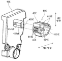
제1 기어부(40)는 케이싱(10)의 제1 방향의 한쪽의 측부에 위치한다. 즉, 제1 기어부(40)는 제1 외표면(11)에 위치한다. 도 4는 제1 기어부(40)가 분해된 상태의 현상 카트리지(1)의 사시도이다. 도 4에 도시한 바와 같이, 제1 기어부(40)는 커플링(41), 현상 기어(42), 아이들 기어(43), 제1 애지테이터 기어(44) 및 제1 커버(45)를 갖는다. 또한, 도 4에서는, 각 기어의 복수의 기어 이의 도시가 생략되어 있다.The
커플링(41)은 화상 형성 장치로부터 공급되는 구동력을, 최초로 받는 기어이다. 커플링(41)은 제1 방향으로 연장되는 회전축 주위로 회전하는 것이 가능하다. 커플링(41)은 커플링부(411)와 커플링 기어(412)를 갖는다. 커플링부(411) 및 커플링 기어(412)는, 예를 들어 일체의 수지에 의해 형성된다. 커플링부(411)에는, 제1 방향으로 오목하게 들어가는 체결 구멍(413)이 마련되어 있다. 또한, 커플링 기어(412)의 외주부에는, 전체 주위에 걸쳐 등간격으로 복수의 기어 이가 마련되어 있다.The
현상 카트리지(1)가 장착된 드로어 유닛(90)이 화상 형성 장치 내에 수납되면, 화상 형성 장치의 구동 샤프트가, 커플링부(411)의 체결 구멍(413)에 삽입된다. 이에 의해, 구동 샤프트와 커플링부(411)가 상대 회전 불가능하게 연결된다. 따라서, 구동 샤프트가 회전하면, 커플링부(411)가 회전하고, 커플링부(411)와 함께 커플링 기어(412)도 회전한다.When the
현상 기어(42)는 현상 롤러(30)를 회전시키기 위한 기어이다. 현상 기어(42)는 제1 방향으로 연장되는 회전축 주위로 회전하는 것이 가능하다. 현상 기어(42)의 외주부에는, 전체 주위에 걸쳐 등간격으로 복수의 기어 이가 마련되어 있다. 커플링 기어(412)의 복수의 기어 이 중 적어도 일부의 기어 이와, 현상 기어(42)의 복수의 기어 이 중 적어도 일부의 기어 이는 서로 맞물려 있다. 또한, 현상 기어(42)는 현상 롤러(30)의 롤러 샤프트(32)의 제1 방향의 단부에, 상대 회전 불가능하게 고정되어 있다. 이 때문에, 커플링 기어(412)가 회전하면, 현상 기어(42)가 회전하고, 현상 기어(42)와 함께 현상 롤러(30)도 회전한다.The developing
아이들 기어(43)는, 커플링 기어(412)의 회전을 제1 애지테이터 기어(44)에 전달하기 위한 기어이다. 아이들 기어(43)는, 제1 방향으로 연장되는 회전축 주위로 회전하는 것이 가능하다. 아이들 기어(43)는, 제1 방향으로 배열된 대직경 기어부(431) 및 소직경 기어부(432)를 갖는다. 소직경 기어부(432)는 대직경 기어부(431)와 케이싱(10)의 제1 외표면(11) 사이에 위치한다. 바꿔 말하면, 대직경 기어부(431)는 소직경 기어부(432)보다도 제1 외표면(11)으로부터 이격되어 있다. 소직경 기어부(432)의 직경은, 대직경 기어부(431)의 직경보다도 작다. 바꿔 말하면, 소직경 기어부(432)의 치선원의 직경은, 대직경 기어부(431)의 치선원의 직경보다도 작다. 대직경 기어부(431) 및 소직경 기어부(432)는, 예를 들어 일체의 수지에 의해 형성된다.The
대직경 기어부(431) 및 소직경 기어부(432)의 외주부에는, 각각, 전체 주위에 걸쳐 등간격으로 복수의 기어 이가 마련되어 있다. 소직경 기어부(432)의 기어 이의 수는, 대직경 기어부(431)의 기어 이의 수보다도 적다. 커플링 기어(412)의 복수의 기어 이 중 적어도 일부의 기어 이와, 대직경 기어부(431)의 복수의 기어 이 중 적어도 일부의 기어 이는 서로 맞물려 있다. 또한, 소직경 기어부(432)의 복수의 기어 이 중 적어도 일부의 기어 이와, 제1 애지테이터 기어(44)의 복수의 기어 이 중 적어도 일부의 기어 이는 서로 맞물려 있다. 커플링 기어(412)가 회전하면, 대직경 기어부(431)가 회전하고, 대직경 기어부(431)와 함께 소직경 기어부(432)도 회전한다. 그리고, 소직경 기어부(432)의 회전에 수반하여, 제1 애지테이터 기어(44)도 회전한다.The outer peripheral parts of the large
제1 애지테이터 기어(44)는 현상제실(13) 내의 애지테이터(20)를 회전시키기 위한 기어이다. 제1 애지테이터 기어(44)는 제1 방향으로 연장되는 회전축 주위로 회전하는 것이 가능하다. 제1 애지테이터 기어(44)의 외주부에는, 전체 주위에 걸쳐 등간격으로 복수의 기어 이가 마련되어 있다. 상술한 바와 같이, 소직경 기어부(432)의 복수의 기어 이 중 적어도 일부의 기어 이와, 제1 애지테이터 기어(44)의 복수의 기어 이 중 적어도 일부의 기어 이는 서로 맞물려 있다. 또한, 제1 애지테이터 기어(44)는 애지테이터 샤프트(21)의 제1 방향의 한쪽의 단부에, 상대 회전 불가능하게 고정되어 있다. 이 때문에, 커플링(41)으로부터 아이들 기어(43)를 통해 제1 애지테이터 기어(44)에 동력이 전달되면, 제1 애지테이터 기어(44)가 회전하고, 제1 애지테이터 기어(44)와 함께 애지테이터(20)도 회전한다.The
제1 커버(45)는 케이싱(10)의 제1 외표면(11)에, 예를 들어 나사 고정으로 고정된다. 커플링 기어(412), 현상 기어(42), 아이들 기어(43) 및 제1 애지테이터 기어(44)는 제1 외표면(11)과 제1 커버(45) 사이에 수용된다. 커플링부(411)의 체결 구멍(413)은 제1 커버(45)의 외부에 노출된다. 본 실시 형태의 제1 커버(45)는 후술하는 IC 칩 어셈블리(60)의 홀더(62)를 보유 지지하는 홀더 커버를 겸하고 있다. 제1 커버(45)의 홀더 커버로서의 구조에 대해서는 후술한다.The
제2 기어부(50)는 케이싱(10)의 제1 방향의 다른 쪽의 측부에 위치한다. 즉, 제2 기어부(50)는 제2 외표면(12)에 위치한다. 도 5는 제2 기어부(50)가 분해된 상태의 현상 카트리지(1)의 사시도이다. 도 5에 도시한 바와 같이, 제2 기어부(50)는 제2 애지테이터 기어(51), 검지 기어(52), 도전 부재(53) 및 제2 커버(54)를 갖는다. 또한, 도 5에서는, 제2 애지테이터 기어(51) 및 검지 기어(52)의 기어 이의 도시가 생략되어 있다.The
제2 애지테이터 기어(51)는 애지테이터 샤프트(21)의 회전을 검지 기어(52)에 전달하기 위한 기어이다. 제2 애지테이터 기어(51)는 제1 방향으로 연장되는 회전축 주위로 회전하는 것이 가능하다. 제2 애지테이터 기어(51)의 외주부에는, 전체 주위에 걸쳐 등간격으로 복수의 기어 이가 마련되어 있다. 제2 애지테이터 기어(51)의 복수의 기어 이 중 적어도 일부의 기어 이와, 검지 기어(52)의 복수의 기어 이 중 적어도 일부의 기어 이는 서로 맞물려 있다. 또한, 제2 애지테이터 기어(51)는 애지테이터 샤프트(21)의 제1 방향의 다른 쪽의 단부에, 상대 회전 불가능하게 고정되어 있다. 이 때문에, 애지테이터 샤프트(21)가 회전하면, 제2 애지테이터 기어(51)도 회전한다.The
검지 기어(52)는 화상 형성 장치에 대하여 현상 카트리지(1)의 정보를 전달하기 위한 기어이다. 현상 카트리지(1)의 정보에는, 예를 들어 현상 카트리지(1)가 신품(미사용)의 현상 카트리지인지, 또는, 사용 완료된 현상 카트리지인지의 정보가 포함된다. 또한, 현상 카트리지(1)의 정보에는, 예를 들어 현상 카트리지(1)의 사양이 포함된다. 현상 카트리지(1)의 사양에는, 예를 들어 현상 카트리지(1)에 수용된 현상제에 의해 인쇄 가능한 인쇄 매수(일드 매수)가 포함된다.The
검지 기어(52)는 제1 방향으로 연장되는 회전축 주위로 회전하는 것이 가능하다. 검지 기어(52)는 외주부의 일부분에 복수의 기어 이를 갖는다. 미사용의 현상 카트리지(1)를 드로어 유닛(90)에 장착하고, 드로어 유닛(90)을 화상 형성 장치 내에 수납하면, 검지 기어(52)는 제2 애지테이터 기어(51)와 맞물림으로써 회전한다. 그리고, 제2 애지테이터 기어(51)와 검지 기어(52)의 맞물림이 해제되면, 검지 기어(52)는 회전을 정지한다.The
한편, 사용 완료된 현상 카트리지(1)를 드로어 유닛(90)에 장착하고, 드로어 유닛(90)을 화상 형성 장치 내에 수납한 경우에는, 검지 기어(52)와, 제2 애지테이터 기어(51)의 맞물림이 해제되어 있기 때문에, 검지 기어(52)는 회전하지 않는다.On the other hand, when the used
또한, 제2 애지테이터 기어(51)와 검지 기어(52) 사이에, 다른 기어가 배치되어 있어도 된다. 예를 들어, 제2 기어부(50)는 제2 애지테이터 기어(51) 및 검지 기어(52)의 양쪽과 맞물리는 제2 아이들 기어를 갖고 있어도 된다. 그리고, 제2 애지테이터 기어(51)의 회전이, 제2 아이들 기어를 통해, 검지 기어(52)에 전달되어도 된다.In addition, another gear may be disposed between the
도 5에 도시한 바와 같이, 검지 기어(52)는 검지 돌기(521)를 갖는다. 검지 돌기(521)는 제1 방향으로 돌출된다. 또한, 검지 돌기(521)는 회전축을 중심으로 하여 원호상으로 연장된다.As shown in FIG. 5, the
도전 부재(53)는 도전성의 부재이다. 도전 부재(53)의 재료에는, 도체인 금속 또는 도전성의 수지가 사용된다. 도전 부재(53)는 케이싱(10)의 제2 외표면(12)에 위치한다. 도전 부재(53)는 제1 방향으로 돌출된 기어 샤프트(531)를 갖는다. 검지 기어(52)는 기어 샤프트(531)에 지지되면서, 기어 샤프트(531)의 주위를 회전한다. 또한, 도전 부재(53)는 베어링부(532)를 갖는다. 베어링부(532)는 현상 롤러(30)의 롤러 샤프트(32)에 접촉한다.The
드로어 유닛(90)은 기어 샤프트(531)에 접촉하는 도전성의 레버(도시 생략)를 갖는다. 기어 샤프트(531)에 레버가 접촉하면, 도전 부재(53) 및 롤러 샤프트(32)가 레버와 전기적으로 도통한다. 화상 형성 장치의 구동 시에는, 레버로부터 공급되는 전력에 의해, 롤러 샤프트(32)가 소정의 바이어스 전압으로 유지된다. 단, 검지 돌기(521)는 기어 샤프트(531)의 외주면을 부분적으로 덮는다. 이 때문에, 드로어 유닛(90)에 새로운 현상 카트리지(1)가 삽입된 후, 검지 기어(52)가 회전하고 있을 때에는, 레버와 기어 샤프트(531)의 접촉 상태가, 검지 기어(52)의 형상에 따라서 변화된다. 화상 형성 장치는, 그 접촉 상태의 변화를 인식함으로써, 장착된 현상 카트리지(1)가 신품인지의 여부, 및 현상 카트리지(1)의 사양을 식별한다.The
단, 검지 기어(52)로부터의 정보의 검지 방법은, 반드시 전기적 도통의 유무를 이용한 것은 아니어도 된다. 예를 들어, 레버의 움직임을, 광학적으로 검지해도 된다. 또한, 검지 돌기(521)의 주위 방향의 위치나 길이는, 본 실시 형태와 상이해도 된다. 또한, 검지 기어(52)는 복수의 검지 돌기(521)를 갖고 있어도 된다. 검지 기어(52)의 형상은, 현상 카트리지(1)의 인쇄 가능 매수 등의 사양에 따라서, 상이하게 할 수 있다. 구체적으로는, 검지 돌기(521)의 수, 복수의 검지 돌기(521)의 주위 방향의 간격, 각 검지 돌기(521)의 주위 방향의 길이, 각 검지 돌기(521)의 직경 방향의 길이 등을, 사양마다 상이하게 할 수 있다. 이와 같이, 검지 돌기(521)의 수나 주위 방향의 위치에 대하여, 베리에이션을 설치함으로써, 현상 카트리지(1)의 다양한 사양을, 화상 형성 장치에 대하여 나타내는 것이 가능해진다.However, the detection method of the information from the
또한, 검지 기어(52)는 복수의 부재로 구성되어 있어도 된다. 예를 들어, 검지 기어(52)와 검지 돌기(521)가 별체여도 된다. 또한, 검지 기어는, 검지 기어 본체와, 검지 기어 본체의 회전에 따라서 위치가 변화되는 보조 부재를 갖고 있어도 된다. 그리고, 보조 부재가 레버의 위치를 변화시켜도 된다.In addition, the
또한, 검지 기어(52)는 제1 방향으로 이동 가능한 가동 기어여도 된다. 가동 기어는, 결치 기어가 아니어도 된다. 즉, 가동 기어는, 그 외주면에, 원주상으로 복수의 기어 이를 갖고 있어도 된다. 이 경우, 가동 기어가 회전하면, 가동 기어가 제1 방향을 향하여 움직임으로써, 가동 기어와 제2 애지테이터 기어(51)의 맞물림이 해제된다. 또한, 가동 기어는, 제2 외표면(12)으로부터 제1 방향으로 이격되는 방향으로 움직여도 된다. 또한, 가동 기어는, 제1 방향으로 제2 외표면(12)에 근접하는 방향으로 움직여도 된다.In addition, the
또한, 검지 기어(52)가 캠을 갖고, 당해 캠이 검지 돌기(521)에 접촉해도 된다. 이 경우, 검지 기어(52)의 회전과 함께 캠이 회전하고, 캠이 회전함으로써 검지 돌기(521)에 접촉하여, 검지 돌기(521)가 움직인다. 검지 돌기(521)는 제2 외표면(12) 또는 제2 커버(54)에 설치된 샤프트에 대하여 회전 가능하게 설치되어 있어도 된다. 또한, 검지 돌기(521)가 갖는 샤프트가, 제2 외표면(12) 또는 제2 커버(54)가 갖는 구멍에 삽입되어, 검지 돌기(521)가 회전 가능하게 보유 지지되어도 된다.In addition, the
또한, 본 실시 형태에서는, 기어 샤프트(531)가 제2 외표면(12)으로부터 제1 방향으로 연장되어 있다. 그러나, 기어 샤프트(531)는 제2 외표면(12)과 직접 접하고 있지 않아도 된다. 예를 들어, 케이싱(10)이 제2 외표면(12)을 관통하는 관통 구멍과, 관통 구멍에 설치된 캡을 더 갖고 있고, 기어 샤프트가 당해 캡으로부터 제1 방향으로 연장되어도 된다. 이 경우, 예를 들어 캡이 검지 기어(52)를 향하여 제1 방향으로 돌출되는 기어 샤프트를 갖는다. 검지 기어(52)는 당해 기어 샤프트에 지지되면서, 기어 샤프트(531)를 중심으로 하여 회전한다.In this embodiment, the
제2 커버(54)는 케이싱(10)의 제2 외표면(12)에, 예를 들어 나사 고정으로 고정된다. 제2 애지테이터 기어(51), 검지 기어(52) 및 도전 부재(53)는 제2 외표면(12)과 제2 커버(54) 사이에 수용된다. 또한, 제2 커버(54)는 개구(541)를 갖는다. 검지 기어(52)의 일부분 및 기어 샤프트(531)의 일부분은, 개구(541)를 통해 노출된다. 상술한 레버는, 개구(541)를 통해, 검지 기어(52) 또는 기어 샤프트(531)에 접촉한다.The
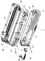
<2. IC 칩 어셈블리에 대하여><2. About IC Chip Assembly>
IC 칩 어셈블리(60)는 케이싱(10)의 제1 외표면(11)에 배치된다. 도 6은 IC 칩 어셈블리(60)의 분해 사시도이다. 도 7은 IC(Integrated Circuit) 칩 어셈블리(60)를 제1 방향에 직교하는 면에서 절단한 단면도이다. 도 2 내지 도 7에 도시한 바와 같이, IC 칩 어셈블리(60)는 기억 매체인 IC 칩(61)과, IC 칩(61)을 보유 지지하는 홀더(62)를 갖는다. 홀더(62)는 케이싱(10)의 제1 방향의 측부에 있어서, 제1 커버(45)에 보유 지지된다. IC 칩(61)에는, 현상 카트리지(1)에 관한 다양한 정보가 기록되어 있다. IC 칩(61)은 전기적 접촉면(611)을 갖는다. 전기적 접촉면(611)은 도체인 금속으로 이루어진다. 이하에서는, 전기적 접촉면(611)과 교차하는 방향[본 실시 형태에서는, 전기적 접촉면(611)에 대하여 수직인 방향]을 「제3 방향」이라 칭한다. IC 칩(61)은 홀더(62)의 제3 방향의 외표면에 고정된다.The
드로어 유닛(90)은 전기 커넥터를 갖는다. 전기 커넥터는, 예를 들어 금속제이다. 현상 카트리지(1)가 드로어 유닛(90)에 장착되면, 드로어 유닛(90)의 전기 커넥터가 전기적 접촉면(611)에 접촉한다. 이에 의해, 화상 형성 장치는, IC 칩(61)으로부터의 정보의 판독 및 IC 칩(61)에의 정보의 기입 중 적어도 한쪽을 행하는 것이 가능해진다.The
홀더(62)의 적어도 일부는, 제1 커버(45)로 덮인다. 홀더(62)는 보스(621a), 보스(621b) 및 보스(621c)를 갖는다. 보스(621a) 및 보스(621b)는, 각각, 홀더(62)의 케이싱(10)과 대향하는 면과는 반대측의 면으로부터 제1 커버(45)를 향하여, 제1 방향으로 연장된다. 또한, 보스(621a)와 보스(621b)는 제2 방향으로 나열된다. 한편, 도 2 및 도 4에 도시한 바와 같이, 제1 커버(45)는 관통 구멍(451a) 및 관통 구멍(451b)을 갖는다. 관통 구멍(451a) 및 관통 구멍(451b)은, 각각, 제1 커버(45)를 제1 방향으로 관통한다. 또한, 관통 구멍(451a)과 관통 구멍(451b)은 제2 방향으로 나열된다. 보스(621a)는 관통 구멍(451a)에 삽입된다. 보스(621b)는 관통 구멍(451b)에 삽입된다.At least a part of the
보스(621c)는 홀더(62)의 케이싱(10)과 대향하는 면으로부터 케이싱(10)을 향하여, 제1 방향으로 연장된다. 한편, 케이싱(10)은 오목부(15)를 갖는다. 오목부(15)는 케이싱(10)의 제1 외표면(11)에 있어서, 제1 방향으로 오목하게 들어간다. 보스(621c)는 오목부(15)에 삽입된다. 또한, 보스(621a), 보스(621b) 및 보스(621c)의 각각의 형상은, 원기둥이어도 되고, 각기둥이어도 된다.The
관통 구멍(451a)의 제2 방향의 크기(내측 치수)는 보스(621a)의 제2 방향의 크기(외측 치수)보다도 크다. 관통 구멍(451b)의 제2 방향의 크기(내측 치수)는 보스(621b)의 제2 방향의 크기(외측 치수)보다도 크다. 또한, 오목부(15)의 제2 방향의 크기(내측 치수)는 보스(621c)의 제2 방향의 크기(외측 치수)보다도 크다. 이 때문에, 홀더(62)는 보스(621a), 보스(621b) 및 보스(621c)와 함께, 케이싱(10) 및 제1 커버(45)에 대하여 제2 방향으로 상대 이동하는 것이 가능하다. 홀더(62)가 제2 방향으로 이동하면, 홀더(62)와 함께, 전기적 접촉면(611)을 갖는 IC 칩(61)도 제2 방향으로 이동한다.The magnitude | size (inner dimension) of the 2nd direction of the through-
또한, 관통 구멍(451a)의 제3 방향의 크기(내측 치수)는 보스(621a)의 제3 방향의 크기(외측 치수)보다도 크다. 관통 구멍(451b)의 제3 방향의 크기(내측 치수)는 보스(621b)의 제3 방향의 크기(외측 치수)보다도 크다. 또한, 오목부(15)의 제3 방향의 크기(내측 치수)는 보스(621c)의 제3 방향의 크기(외측 치수)보다도 크다. 이 때문에, 홀더(62)는 보스(621a), 보스(621b) 및 보스(621c)와 함께, 케이싱(10) 및 제1 커버(45)에 대하여 제3 방향으로 상대 이동하는 것이 가능하다. 홀더(62)가 제3 방향으로 이동하면, 홀더(62)와 함께, 전기적 접촉면(611)을 갖는 IC 칩(61)도, 제3 방향으로 이동한다. 또한, 홀더(62)는 제1 커버(45)와, 제1 외표면(11) 사이를 제1 방향으로 이동 가능해도 된다.Moreover, the magnitude | size (inner dimension) of the 3rd direction of the through
또한, 홀더(62)에 설치되는 보스의 수는 1개여도 되고, 3개 이상이어도 된다. 또한, 제1 커버(45)에 형성되는 관통 구멍의 수도 1개여도 되고, 3개 이상이어도 된다. 또한, 제1 커버(45)는 관통 구멍(451a) 및 관통 구멍(451b) 대신에, 보스(621a) 및 보스(621b)가 삽입되는 오목부를 갖고 있어도 된다.In addition, the number of bosses provided in the
도 6 및 도 7에 도시한 바와 같이, 홀더(62)는 제1 단부(710)와, 제2 단부(720)를 갖는다. 제1 단부(710)는 홀더(62)의 제3 방향의 한쪽의 단부이다. 또한, 제2 단부(720)는 홀더(62)의 제3 방향의 다른 쪽의 단부이다. 제1 단부(710)는 제2 단부(720)에 대하여 제3 방향으로 이동 가능하다. 보다 상세하게는, 본 실시 형태의 홀더(62)는 제1 홀더 부재(71)와, 제2 홀더 부재(72)와, 제1 홀더 부재(71)와 제2 홀더 부재(72) 사이에 위치하는 코일 스프링(73)을 갖는다. 제1 홀더 부재(71)는 예를 들어 수지제이다. 제2 홀더 부재(72)는 예를 들어 수지제이다. 제1 홀더 부재(71)는 제1 단부(710)를 갖는다. IC 칩(61)은 제1 단부(710)의 외표면에 포함되는 보유 지지면(620)에 고정된다. 제2 홀더 부재(72)는 제2 단부(720)를 갖는다. 조립 후의 홀더(62)에 있어서, 제1 단부(710)와 제2 단부(720)는 제3 방향으로 이격되어 있다.As shown in FIGS. 6 and 7, the
코일 스프링(73)은 제3 방향으로 연장되는 탄성 부재이다. 코일 스프링(73)은 제3 방향에 있어서, 제1 단부(710)와 제2 단부(720) 사이에 배치된다. 코일 스프링(73)은 적어도, 제1 상태와, 제1 상태보다도 수축된 제2 상태 사이에서, 제3 방향으로 신축한다. 제1 상태에 있어서의 코일 스프링(73)의 제3 방향의 길이는, 제2 상태에 있어서의 코일 스프링(73)의 제3 방향의 길이보다도 길다. 따라서, 제1 상태에 있어서의 제1 단부(710)와 제2 단부(720) 사이의 제3 방향의 거리는, 제2 상태에 있어서의 제1 단부(710)와 제2 단부(720) 사이의 제3 방향의 거리보다도 길다. 또한, 적어도 제2 상태에 있어서의 코일 스프링(73)의 제3 방향의 길이는, 코일 스프링(73)의 자연 길이보다도 짧다.The
또한, 도 6 및 도 7에 도시한 바와 같이, 제1 홀더 부재(71)는 갈고리부(714a) 및 갈고리부(714b)를 갖는다. 갈고리부(714a) 및 갈고리부(714b)는 각각, 제1 홀더 부재(71)로부터 제3 방향에 대하여 교차하는 방향으로 돌출된다. 한편, 제2 홀더 부재(72)는 개구(721a) 및 개구(721b)를 갖는다. 갈고리부(714a)는 개구(721a)에 삽입된다. 갈고리부(714b)는 개구(721b)에 삽입된다. 제1 상태에서는, 개구(721a)의 제1 단부(710)측의 에지에 있어서, 갈고리부(714a)가 제2 홀더 부재(72)에 접촉한다. 또한, 제1 상태에서는, 개구(721b)의 제1 단부(710)측의 에지에 있어서, 갈고리부(714b)가 제2 홀더 부재(72)에 접촉한다. 이에 의해, 코일 스프링(73)의 제3 방향의 길이가, 제1 상태보다도 길어지는 것이 방지된다. 또한, 제1 홀더 부재(71)가 제2 홀더(72)로부터 빠지는 것이 방지된다. 한편, 제2 상태에서는, 갈고리부(714a) 및 갈고리부(714b)가 제2 홀더 부재(72)의 개구(721b)의 제1 단부(710)측의 에지로부터 이격된다.6 and 7, the
또한, 개구 대신에, 갈고리부에 접촉 가능한 오목부 또는 단차가 마련되어도 된다. 또한, 제1 홀더 부재(71)에 개구, 오목부 또는 단차를 마련하고, 제2 홀더 부재(72)에 갈고리부를 마련해도 된다.In addition, instead of the opening, a concave portion or step that can contact the hook portion may be provided. In addition, an opening, a recess or a step may be provided in the
상술한 관통 구멍(451) 및 보스(621)의 치수차와, 코일 스프링(73)의 신축에 의해, 홀더(62)의 보유 지지면(620)은 케이싱(10)에 대하여 제3 방향으로 이동하는 것이 가능하다. 이하에서는, 드로어 유닛(90)에 현상 카트리지(1)를 장착하기 전의, 케이싱(10)에 대한 보유 지지면(620)의 제3 방향의 위치를, 「초기 위치」라 칭한다. 또한, 드로어 유닛(90)에의 현상 카트리지(1)의 장착 시에 있어서, 코일 스프링(73)이 가장 수축되는 순간의, 케이싱(10)에 대한 보유 지지면(620)의 제3 방향의 위치를, 「중간 위치」라 칭한다. 또한, 후술하는 전기 커넥터(913)에 전기적 접촉면(611)이 접촉하였을 때의, 케이싱(10)에 대한 보유 지지면(620)의 제3 방향의 위치를, 「접촉 위치」라 칭한다. 그리고, 드로어 유닛(90)에의 현상 카트리지(1)의 장착이 완료된 후의, 케이싱(10)에 대한 보유 지지면(620)의 제3 방향의 위치를, 「종기 위치」라 칭한다.The holding
또한, 제1 단부(710)의 외표면은, 상술한 보유 지지면(620)에 더하여, 제1 표면(711), 제2 표면(712) 및 제3 표면(713a, 713b)을 더 갖는다.The outer surface of the
제1 표면(711)은 보유 지지면(620)의 제2 방향의 양측부 중, 현상 롤러(30)에 가까운 측부에 설치된다. 제1 표면(711)은 보유 지지면(620)에 보유 지지된 IC 칩(61)의 전기적 접촉면(611)에 대하여 경사져 있다. 상세하게는, 제1 표면(711)은 전기적 접촉면(611)에 대하여 예각으로 경사져 있다.The
여기서, 제1 단부(710)의 제2 방향의 한쪽의 단부를, 제1 외측 단부 위치(제3 위치)(711a)라 한다. 또한, 보유 지지면(620)의 제2 방향의 한쪽의 단부를, 제1 내측 단부 위치(제4 위치)(711b)라 한다. 도 7과 같이, 제1 표면(711)은 제1 외측 단부 위치(711a)로부터 전기적 접촉면(611)을 향하여 제1 내측 단부 위치(711b)까지 연장되어 있다. 제2 방향 및 제3 방향 중 어느 것에서도, 제1 외측 단부 위치(711a)는 제1 내측 단부 위치(711b)보다도 전기적 접촉면(611)으로부터 멀다. 또한, 도 7에 도시한 바와 같이, 제1 외측 단부 위치(711a)와 제1 내측 단부 위치(711b) 사이의 제3 방향의 거리 d1은, 전기적 접촉면(611)과 제1 내측 단부 위치(711b) 사이의 제3 방향의 거리 d2보다도 크다.Here, one end part in the 2nd direction of the
제2 표면(712)은 보유 지지면(620)의 제2 방향의 양측부 중, 현상 롤러(30)로부터 먼 측부에 설치된다. 제2 표면(712)은 보유 지지면(620)에 보유 지지된 IC 칩(61)의 전기적 접촉면(611)에 대하여 경사져 있다. 상세하게는, 제2 표면(712)은 전기적 접촉면(611)에 대하여 예각으로 경사져 있다.The
여기서, 제1 단부(710)의 제2 방향의 다른 쪽의 단부를, 제2 외측 단부 위치(제5 위치)(712a)라 한다. 또한, 보유 지지면(620)의 제2 방향의 다른 쪽의 단부를, 제2 내측 단부 위치(제6 위치)(712b)라 한다. 도 7과 같이, 제2 표면(712)은 제2 외측 단부 위치(712a)로부터 전기적 접촉면(611)을 향하여 제2 내측 단부 위치(712b)까지 연장되어 있다. 제2 방향 및 제3 방향 중 어느 것에서도, 제2 외측 단부 위치(712a)는 제2 내측 단부 위치(712b)보다도 전기적 접촉면(611)으로부터 멀다. 또한, 도 7에 도시한 바와 같이, 제2 외측 단부 위치(712a)와 제2 내측 단부 위치(712b) 사이의 제3 방향의 거리 d3은, 전기적 접촉면(611)과 제2 내측 단부 위치(712b) 사이의 제3 방향의 거리 d4보다도 크다.Here, the other end part in the 2nd direction of the
제3 표면(713a)은 제1 방향에 있어서, 전기적 접촉면(611)의 양측 중 한쪽에 설치된다. 제3 표면(713b)은 제1 방향에 있어서, 전기적 접촉면(611)의 양측 중 다른 쪽에 설치된다. 제3 표면(713a) 및 제3 표면(713b)은 각각, 제2 방향으로 연장되어 있다. 또한, 제3 방향에 관하여, 각 제3 표면(713a, 713b)은 전기적 접촉면(611)보다도, 코일 스프링(73)으로부터 멀다. 따라서, 전기적 접촉면(611)은 제3 표면(713a) 및 제3 표면(713b)보다도, 코일 스프링(73)측으로 오목하게 들어간 위치에 배치된다.The
또한, 제1 표면(711), 제2 표면(712) 및 제3 표면(713a, 713b)은, 각각 평면상이어도 되고, 만곡되어 있어도 된다. 단, 드로어 유닛(90)에의 현상 카트리지(1)의 장착 시에 걸림이 발생하지 않도록, 제1 표면(711), 제2 표면(712) 및 제3 표면(713a, 713b)은, 각각, 단차가 없는 매끄러운 면인 것이 바람직하다.In addition, the
<3. 장착 시의 동작에 대하여><3. About operation when mounted>
계속해서, 드로어 유닛(90)에 대한 현상 카트리지(1)의 장착 시의 동작에 대하여 설명한다. 도 8 내지 도 14는 드로어 유닛(90)의 1개의 카트리지 보유 지지부(91)에 대하여, 현상 카트리지(1)를 장착할 때의 모습을 도시한 도면이다.Subsequently, an operation when the developing
카트리지 보유 지지부(91)에 현상 카트리지(1)가 장착될 때에는, 먼저, 도 8과 같이, 카트리지 보유 지지부(91)의 삽입구(910)에, 현상 카트리지(1)의 현상 롤러(30)가 대향된다. 이때, 홀더(62)의 제1 단부(710) 및 제2 단부(720)는 아직 드로어 유닛(90)에 접촉하고 있지 않다. 따라서, 코일 스프링(73)은 상술한 제1 상태로 되어 있다. 또한, 케이싱(10)에 대한 보유 지지면(620)의 제3 방향의 위치는, 상술한 초기 위치로 되어 있다. 현상 카트리지(1)는 도 8 중의 파선 화살표와 같이, 카트리지 보유 지지부(91)에 대하여 제2 방향으로 삽입된다.When the developing
카트리지 보유 지지부(91)는 제1 가이드 플레이트(911) 및 제2 가이드 플레이트(912)를 갖는다. 제1 가이드 플레이트(911) 및 제2 가이드 플레이트(912)는 제3 방향으로 간격을 두고, 서로 대향하여 배치된다. 제1 가이드 플레이트(911) 및 제2 가이드 플레이트(912)는 각각, 제1 방향 및 제2 방향을 따라서 펼쳐진다. 또한, 제1 가이드 플레이트(911)는 IC 칩(61)의 전기적 접촉면(611)에 접촉 가능한 금속제의 전기 커넥터(913)를 갖는다. 전기 커넥터(913)는 제1 가이드 플레이트(911)의 표면으로부터, 제2 가이드 플레이트(912)를 향하여, 제3 방향으로 돌출된다.The
카트리지 보유 지지부(91)에 현상 카트리지(1)가 삽입되면, 도 9와 같이, 홀더(62)의 제1 표면(711)이 제1 가이드 플레이트(911)의 제2 방향의 단부에 접촉한다. 그리고, 제1 표면(711)이 제1 가이드 플레이트(911)에 눌러짐으로써, 홀더(62)가 제3 방향으로 이동한다. 이때의 홀더(62)의 이동은, 케이싱(10)에 대한 상대 이동이다. 이에 의해, 도 10과 같이, 제1 가이드 플레이트(911)와 제2 가이드 플레이트(912) 사이에, 홀더(62)가 제3 방향으로 위치 결정된다.When the developing
이후, 제1 홀더 부재(71)의 제1 단부(710)는 제1 가이드 플레이트(911)에 접촉한다. 또한, 제2 홀더 부재(72)의 제2 단부(720)는 제2 가이드 플레이트(912)에 접촉한다. 코일 스프링(73)은 제1 상태보다도 제3 방향으로 수축된다.Thereafter, the
도 11에 도시한 바와 같이, 제1 가이드 플레이트(911)는 제2 가이드 플레이트(912)를 향하여 돌출되는 가이드 돌기(914)를 갖는다. 가이드 돌기(914)는 전기 커넥터(913)보다도 삽입구(910)측에 위치한다. 가이드 돌기(914)는 제1 경사면(915)을 갖는다. 또한, 제2 가이드 플레이트(912)는 제2 경사면(916)을 갖는다. 제1 경사면(915)과 제2 경사면(916)의 제3 방향의 간격은, 현상 카트리지(1)의 삽입 방향으로 감에 따라, 점차 짧아진다.As illustrated in FIG. 11, the
현상 카트리지(1)를 제2 방향으로 더 삽입하면, 제1 홀더 부재(71)는 제1 경사면(915)에 접촉하고, 제2 홀더 부재(72)는 제2 경사면(916)에 접촉한다. 이에 의해, 제1 홀더 부재(71)와 제2 홀더 부재(72)가 제3 방향으로 접근하고, 코일 스프링(73)의 제3 방향의 길이가 서서히 짧아진다. 마침내, 제1 홀더 부재(71)의 제3 표면(713a, 713b)이 가이드 돌기(914)의 정상부에 접촉하면, 코일 스프링(73)의 제3 방향의 길이는 가장 짧아진다. 즉, 코일 스프링(73)이 상술한 제2 상태보다도 짧은 최단 상태로 된다. 또한, 케이싱(10)에 대한 보유 지지면(620)의 제3 방향의 위치는, 상술한 중간 위치로 된다.When the developing
이와 같이, 이 IC 칩 어셈블리(60)는 드로어 유닛(90)에의 현상 카트리지(1)의 삽입 시에, IC 칩(61)을 보유 지지하는 보유 지지면(620)의 위치를, 제3 방향으로 변화시킬 수 있다. 이 때문에, 보유 지지면(620)의 제3 방향의 위치를, 가이드 돌기(914)를 따라서 변화시키면서, 현상 카트리지(1)를 삽입할 수 있다. 따라서, IC 칩(61)의 전기적 접촉면(611)의 마찰을 억제하면서, 드로어 유닛(90)에 현상 카트리지(1)를 삽입할 수 있다. 또한, 도 10, 도 11 및 도 12에 도시한 바와 같이, 제1 표면(711)이 가이드 돌기(914)를 타고 넘은 후에, 전기적 접촉면(611)은 직접 전기 커넥터(913)에 접촉한다. 이에 의해, 전기 커넥터(913)의 마찰도 저감할 수 있다.In this manner, the
특히, 본 실시 형태의 현상 카트리지(1)에서는, IC 칩(61)의 전기적 접촉면(611)이 제3 표면(713a, 713b)보다도 오목하게 들어간 위치에 배치되어 있다. 이 때문에, 도 11의 상태에 있어서, 가이드 돌기(914)의 정상부는, 제3 표면(713a, 713b)과만 접촉하고, 전기적 접촉면(611)에는 접촉하지 않는다. 따라서, 가이드 돌기(914)가 전기적 접촉면(611)에 마찰되는 것을 피할 수 있다.In particular, in the developing
그 후, 현상 카트리지(1)를 제2 방향으로 더 삽입하면, 제3 표면(713a, 713b)이 가이드 돌기(914)를 통과한다. 그리고, 도 12와 같이, 제2 표면(712)이 가이드 돌기(914)에 접촉한다. 이것에 수반하여, 코일 스프링(73)은 최단 상태로부터 다시 신장되어, 상술한 제2 상태로 된다. 그 결과, 도 13과 같이, IC 칩(61)의 전기적 접촉면(611)이 전기 커넥터(913)에 접촉한다. 제2 상태에 있어서의 코일 스프링(73)의 제3 방향의 길이는, 제1 상태에 있어서의 코일 스프링(73)의 제3 방향의 길이보다도 짧고, 또한, 최단 상태에 있어서의 코일 스프링(73)의 제3 방향의 길이보다도 길다. 또한, 제2 상태에 있어서의 코일 스프링(73)의 제3 방향의 길이는, 코일 스프링(73)의 자연 길이보다도 짧다. 또한, 케이싱(10)에 대한 보유 지지면(620)의 제3 방향의 상대 위치는 상술한 접촉 위치로 된다.Thereafter, when the developing
이에 의해, IC 칩 어셈블리(60)는 전기 커넥터(913)와 제2 가이드 플레이트(912) 사이에 끼워진 상태에서 고정된다. 그 후, 본 실시 형태에서는, 도 14 중의 파선 화살표와 같이, 케이싱(10)이 제3 방향으로 기울어진다. 이에 의해, 드로어 유닛(90)의 감광 드럼(92)에, 현상 롤러(30)가 접촉한다. 이때, 케이싱(10)에 대한 보유 지지면(620)의 제3 방향의 위치는, 상술한 접촉 위치로부터 종기 위치로 변화된다. 또한, 보스(621)는 관통 구멍(451) 내에 있어서 제3 방향으로 이동한다. 이에 의해, 제1 커버(45)의 관통 구멍(451)을 구성하는 에지부에 대하여, 보스(621)가 비접촉으로 된다. 그 결과, IC 칩 어셈블리(60)와 제1 커버(45)가 비접촉으로 된다. 따라서, 화상 형성 장치에 있어서의 인쇄 처리의 실행 중에, 제1 기어부(40) 등의 구동부로부터, IC 칩 어셈블리(60)에 진동이 전달되기 어려워진다. 이에 의해, 전기적 접촉면(611)과 전기 커넥터(913)의 접촉 상태를, 보다 양호하게 유지할 수 있다.Thereby, the
<4. 이격 동작에 대하여><4. About separation action
현상 카트리지(1)의 장착 후, 드로어 유닛(90)은 현상 롤러(30)를 일시적으로 감광 드럼(92)으로부터 분리하는, 소위 「이격 동작」을 행할 수 있다. 도 2에 도시한 바와 같이, 현상 카트리지(1)의 제1 커버(45)는 제1 방향으로 연장되는 제1 주상 돌기(46)를 갖는다. 또한, 도 3에 도시한 바와 같이, 현상 카트리지(1)의 제2 커버(54)는 제1 방향으로 연장되는 제2 주상 돌기(55)를 갖는다. 한편, 도 1에 도시한 바와 같이, 드로어 유닛(90)은 복수의 압박 부재(93)를 갖는다. 압박 부재(93)는 각 카트리지 보유 지지부(91)의 제1 방향의 양측부에 설치되어 있다.After attaching the developing
상술한 도 14의 파선 화살표의 동작에서는, 제1 주상 돌기(46) 및 제2 주상 돌기(55)의 각각이, 압박 부재(93)에 의해 압박된다. 이에 의해, 케이싱(10)이 제3 방향으로 기울어진다. 그 결과, 케이싱(10)에 대한 보유 지지면(620)의 제3 방향의 위치가, 상술한 접촉 위치로부터 종기 위치로 변화된다.In the operation of the broken line arrow in FIG. 14 described above, each of the first
도 15는 이격 동작을 실행하였을 때의 모습을 도시한 도면이다. 이격 동작 시에는, 화상 형성 장치로부터의 구동력에 의해, 제1 주상 돌기(46) 및 제2 주상 돌기(55)의 위치가 변화된다. 구체적으로는, 제1 주상 돌기(46) 및 제2 주상 돌기(55)의 각각이, 드로어 유닛(90)이 갖는 레버(도시 생략)에 눌린다. 이에 의해, 제1 주상 돌기(46) 및 제2 주상 돌기(55)의 각각이, 압박 부재(93)의 압박력에 반하여 이동한다. 그 결과, 도 15 중의 파선 화살표와 같이, 현상 카트리지(1)의 케이싱(10) 및 현상 롤러(30)가 제2 방향으로 이동하여, 감광 드럼(92)으로부터 멀어진다.FIG. 15 is a diagram illustrating a state when a spaced operation is performed. FIG. In the separation operation, the positions of the first
이때, IC 칩 어셈블리(60)는 전기 커넥터(913)와 제2 가이드 플레이트(912) 사이에 끼워진 상태에서 고정되어 있다. 이 때문에, 케이싱(10) 및 현상 롤러(30)가 제2 방향으로 이동하면서도, 드로어 유닛(90)에 대한 IC 칩 어셈블리(60)의 위치는 변화되지 않는다. 또한, 코일 스프링(73)의 상태도, 제2 상태 그대로 변화되지 않는다. 따라서, 케이싱(10)에 대한 홀더(62)의 제2 방향의 위치는, 표준 위치(제1 위치)로부터 이격 위치(제2 위치)로 변화된다. 또한, 보스(621)는 관통 구멍(451)의 내부에 있어서, 제2 방향으로 이동한다.At this time, the
이와 같이, 이 현상 카트리지(1)는 드로어 유닛(90)에 대한 전기적 접촉면(611)의 제2 방향의 위치를 변화시키지 않고, 케이싱(10)의 제2 방향의 위치를 변화시킬 수 있다. 이 때문에, 이격 동작을 실행할 때에, 전기적 접촉면(611)과 전기 커넥터(913)의 접촉 상태를 유지할 수 있다. 또한, 현상 카트리지(1)가 드로어 유닛(90)에 장착된 상태에서, 화상 형성 장치가 수송될 때에도, 전기적 접촉면(611)과 전기 커넥터(913)의 접촉 상태를 유지할 수 있기 때문에, 전기적 접촉면(611)의 마찰을 저감할 수 있다.In this manner, the developing
<5. 변형예><5. Variation>
이상, 본 발명의 일 실시 형태에 대하여 설명하였지만, 본 발명은 상기의 실시 형태에 한정되는 것은 아니다. 이하에서는, 다양한 변형예에 대하여, 상기의 실시 형태와의 상위점을 중심으로 설명한다.As mentioned above, although one Embodiment of this invention was described, this invention is not limited to said embodiment. Below, various modifications are demonstrated centering on difference with said embodiment.
<5-1. 제1 변형예><5-1. First modification>
도 16은 제1 변형예의 현상 카트리지(1A)의 부분 분해 사시도이다. 도 16의 예에서는, 상기의 실시 형태와 마찬가지로, IC 칩(61A)을 보유 지지하는 홀더(62A)의 적어도 일부가, 제1 커버(45A)로 덮인다. 단, 도 16의 예에서는, 제1 커버(45A)가 보스(451aA, 451bA)를 갖는다. 보스(451aA)와 보스(451bA)는, 제2 방향으로 배열된다. 또한, 보스(451aA, 451bA)는, 각각, 제1 커버(45A)로부터 케이싱(10A)을 향하여, 제1 방향으로 연장된다. 한편, 홀더(62A)는, 제1 방향으로 관통하는 1개의 관통 구멍(621A)을 갖는다. 보스(451aA, 451bA)는, 모두, 관통 구멍(621A)에 삽입된다.16 is a partially exploded perspective view of the developing
관통 구멍(621A)의 제2 방향의 크기는, 보스(451aA)의 제2 방향의 한쪽의 단부 에지와, 보스(451bA)의 제2 방향의 다른 쪽의 단부 에지 사이의 길이보다도 크다. 즉, 관통 구멍(621A)의 제2 방향의 크기는, 보스(451aA, 451bA)의 제2 방향으로 가장 이격된 부분끼리의 제2 방향의 거리보다도 크다. 이 때문에, 홀더(62A)는, 관통 구멍(621A)과 함께, 케이싱(10A) 및 제1 커버(45A)에 대하여 제2 방향으로 이동하는 것이 가능하다. 홀더(62A)가 제2 방향으로 이동하면, 홀더(62A)와 함께, 전기적 접촉면(611A)을 갖는 IC 칩(61A)도, 제2 방향으로 이동한다.The magnitude | size of the 2nd direction of the through-
또한, 관통 구멍(621A)의 제3 방향의 크기는, 각 보스(451aA, 451bA)의 제3 방향의 크기보다도 크다. 이 때문에, 홀더(62A)는, 관통 구멍(621A)과 함께, 케이싱(10A) 및 제1 커버(45A)에 대하여 제3 방향으로 이동하는 것이 가능하다. 홀더(62A)가 제3 방향으로 이동하면, 홀더(62A)와 함께, 전기적 접촉면(611A)을 갖는 IC 칩(61A)도, 제3 방향으로 이동한다. 또한, 홀더(62A)도, 제1 커버(45A)와, 제1 외표면(11A) 사이를 제1 방향으로 이동 가능해도 된다.The size of the through
이와 같이, 제1 커버(45A)에 보스(451A)를 설치하고, 홀더(62A)에 관통 구멍(621A)을 마련함으로써, 케이싱(10A)에 대한 전기적 접촉면(611A)의 제2 방향 및 제3 방향의 이동을 실현해도 된다. 이와 같은 구조에서도, 드로어 유닛에의 현상 카트리지(1A)의 장착 시에, 케이싱(10A)을 제3 방향으로 기울어지게 하였을 때에, 관통 구멍(621A)의 내부에 있어서, 보스(451A)를 제3 방향으로 이동시킬 수 있다. 또한, 현상 카트리지(1A)의 장착 후에, 이격 동작을 실행하였을 때에, 관통 구멍(621A)의 내부에 있어서, 보스(451A)를 제2 방향으로 이동시킬 수 있다. 그 결과, 전기적 접촉면(611A)과 전기 커넥터의 접촉 상태를 양호하게 유지하면서, 케이싱(10A)의 위치를 변화시킬 수 있다.In this way, the boss 451A is provided in the
또한, 제1 커버(45A)에 설치되는 보스(451A)의 수는 1개여도 되고, 3개 이상이어도 된다. 또한, 홀더(62A)에 형성되는 관통 구멍(621A)의 수는 2개 이상이어도 된다. 또한, 홀더(62A)는, 관통 구멍(621A) 대신에, 보스(451A)가 삽입되는 오목부를 갖고 있어도 된다. 또한, 케이싱의 제1 외표면에 보스를 설치하고, 홀더가 갖는 관통 구멍 또는 오목부에, 케이싱의 보스를 삽입해도 된다. 보스(451A)는, 원기둥이어도 되고, 각기둥이어도 된다.In addition, the number of bosses 451A provided on the
도 17은, 도 16의 IC 칩 어셈블리(60A)를, 제1 방향에 수직인 면에서 절단한 단면도이다. 도 17에 도시한 바와 같이, 이 IC 칩 어셈블리(60A)의 홀더(62A)는, 수지제의 홀더 부재(74A)와, 홀더 부재(74A)에 고정된 판 스프링(75A)을 갖는다. 홀더 부재(74A)는, 홀더(62A)의 제3 방향의 한쪽의 단부인 제1 단부(740A)를 갖는다. IC 칩(61A)은, 제1 단부(740A)의 외표면에 포함되는 보유 지지면(620A)에 고정된다. 판 스프링(75A)은, 홀더(62A)의 제3 방향의 다른 쪽의 단부인 제2 단부(750A)를 갖는다. 조립 후의 홀더(62A)에 있어서, 제1 단부(740A)와 제2 단부(750A)는, 제3 방향으로 이격되어 있다.FIG. 17 is a cross-sectional view of the
판 스프링(75A)에는, 예를 들어 가요성을 갖는 굴절된 금속판이 사용된다. 판 스프링(75A)은, 적어도, 제1 상태와, 제1 상태보다도 굴절된 제2 상태 사이에서, 제3 방향으로 신축한다. 제1 상태에 있어서의 판 스프링(75A)의 제3 방향의 길이는, 제2 상태에 있어서의 판 스프링(75A)의 제3 방향의 길이보다도 길다. 따라서, 제1 상태에 있어서의 제1 단부(740A)와 제2 단부(750A) 사이의 제3 방향의 거리는, 제2 상태에 있어서의 제1 단부(740A)와 제2 단부(750A) 사이의 제3 방향의 거리보다도 길다. 또한, 적어도 제2 상태에 있어서의 판 스프링(75A)의 제3 방향의 길이는, 판 스프링(75A)의 자연 길이보다도 짧다.As the
이와 같이, 코일 스프링 대신에 판 스프링(75A)을 사용함으로써, IC 칩 어셈블리(60A)를 제3 방향으로 신축시켜도 된다. 드로어 유닛에 현상 카트리지(1A)를 장착할 때에는, 상술한 보스(451A) 및 관통 구멍(621A)의 치수차와, 판 스프링(75A)의 신축에 의해, IC 칩(61A)의 전기적 접촉면(611A)을, 케이싱(10A)에 대하여 제3 방향으로 이동시킬 수 있다.In this way, the
<5-2. 제2 변형예><5-2. Second Modification>
도 18은 제2 변형예의 현상 카트리지(1B)의 부분 사시도이다. 도 18의 예에서는, IC 칩(61B)의 전기적 접촉면(611B)이, 제1 방향으로 향해져 있다. 따라서, 전기적 접촉면(611B)에 직교하는 제3 방향과, 제1 방향이 동일 방향으로 된다. 또한, 도 18의 예에서는, 케이싱(10B)과 IC 칩 어셈블리(60B) 사이에, 주상 탄성체(63B)가 설치되어 있다. 주상 탄성체(63B)에는, 예를 들어 제3 방향으로 연장되는 코일 스프링이 사용된다. 주상 탄성체(63B)의 제1 방향의 일단은, IC 칩 어셈블리(60B)의 홀더(62B)에 고정된다. 주상 탄성체(63B)의 제1 방향의 타단은, 케이싱(10B)의 제1 외표면에 고정된다. 즉, 케이싱(10B)과 IC 칩 어셈블리(60B)가, 주상 탄성체(63B)에 의해 연결되어 있다.18 is a partial perspective view of the developing
도 19 및 도 20은 주상 탄성체(63B)의 변형에 의한 IC 칩 어셈블리(60B)의 움직임을 도시한 도면이다. 도 19에 도시한 바와 같이, 주상 탄성체(63B)는, 제3 방향으로 신축 가능하다. 주상 탄성체(63B)가 신축하면, 케이싱(10B)에 대한 전기적 접촉면(611B)의 제3 방향의 위치도 변화된다. 또한, 도 20에 도시한 바와 같이, 주상 탄성체(63B)는, 제3 방향에 대하여 비스듬히 변형 가능하다. 주상 탄성체(63B)가 비스듬히 변형되면, 주상 탄성체(63B)의 일단과 타단의 상대 위치가, 제3 방향에 대하여 교차하는 방향 또는 수직인 방향으로 변화된다.19 and 20 show the movement of the
도 21 및 도 22는, 제2 변형예의 현상 카트리지(1B)를, 드로어 유닛(90B)에 장착할 때의 모습을 도시한 도면이다. 도 21 및 도 22에 도시한 바와 같이, 제1 커버(45B)는, 제2 방향으로 간격을 두고 나열되는 제1 프레임부(456B) 및 제2 프레임부(457B)를 갖는다. IC 칩 어셈블리(60B) 및 주상 탄성체(63B)는, 제1 프레임부(456B)와 제2 프레임부(457B) 사이의 공간인 수용부(452B)에 수용된다. 또한, 제1 커버(45B)는, 제1 프레임부(456B)로부터 수용부(452B)를 향하여 돌출되는 갈고리부(453B)를 갖는다. 현상 카트리지(1B)를 드로어 유닛(90B)에 장착하기 전에는, 도 21과 같이, IC 칩 어셈블리(60)의 일부분이, 갈고리부(453B)에 접촉한다. 이에 의해, 주상 탄성체(63B)가, 자연 길이보다도 제3 방향으로 압축된 상태로 유지된다.21 and 22 are views showing a state when the developing
현상 카트리지(1B)가 드로어 유닛(90B)에 장착되면, 도 22와 같이, IC 칩(61B)의 전기적 접촉면(611B)이 전기 커넥터(913B)에 접촉한다. 이때, 주상 탄성체(63B)의 제3 방향의 길이는, 도 21의 상태보다도 짧아진다. 따라서, 주상 탄성체(63B)의 반발력에 의해, 전기적 접촉면(611B)과 전기 커넥터(913B)의 접촉 상태가 유지된다.When the developing
도 23은 현상 카트리지(1B)의 장착 후에, 이격 동작을 실행하였을 때의 모습을 도시한 도면이다. 이격 동작 시에는, 도 23과 같이, 주상 탄성체(63B)가, 제3 방향에 대하여 비스듬히 변형된다. 이에 의해, 주상 탄성체(63B)의 일단에 접속된 IC 칩 어셈블리(60B)와, 주상 탄성체(63B)의 타단에 접속된 케이싱(10B)이, 제2 방향으로 상대 이동한다. 따라서, 드로어 유닛(90B)에 대한 전기적 접촉면(611B)의 제2 방향의 위치를 변화시키지 않고, 케이싱(10B)의 제2 방향의 위치를 변화시킬 수 있다. 즉, 전기적 접촉면(611B)과 전기 커넥터(913B)의 접촉 상태를 유지하면서, 이격 동작을 행할 수 있다.FIG. 23 is a diagram showing a state when the separation operation is performed after the
<5-3. 제3 변형예><5-3. Third modification>
도 24는 제3 변형예의 현상 카트리지(1C)의 사시도이다. 도 24의 예에서는, IC 칩 어셈블리(60C)가, IC 칩(61C), 홀더(62C), 샤프트부(66C) 및 레버(67C)를 갖는다. 샤프트부(66C)는, 제1 커버(45C)의 내부에 있어서, 제2 방향으로 연장된다. 샤프트부(66C)의 제2 방향의 일단은, 홀더(62C)에, 상대 회전 불가능하게 접속된다. 샤프트부(66C)의 제2 방향의 타단은, 제1 커버(45C)의 외부에 배치된 레버(67C)에, 상대 회전 불가능하게 접속된다. 따라서, 도 24의 파선 화살표와 같이, 샤프트부(66C)를 중심으로 하여 레버(67C)를 회전시키면, 샤프트부(66C) 및 홀더(62C)도, 샤프트부(66C)를 중심으로 하여 회전한다. 이에 의해, 홀더(62C)의 제3 방향의 위치가 변화된다.24 is a perspective view of the
도 25 내지 도 27은 제3 변형예의 현상 카트리지(1C)를, 제1 방향의 일방측으로부터 본 도면이다. 드로어 유닛에 현상 카트리지(1C)를 장착하기 전에는, 도 24 및 도 25와 같이, 제1 커버(45C)의 내부에, IC 칩(61C) 및 홀더(62C)가 수용되어 있다. 드로어 유닛에 현상 카트리지(1C)를 장착하고, 드로어 유닛을 화상 형성 장치에 수납하면, 샤프트부(66C)를 중심으로 하여, 레버(67C)가 회전한다. 이에 의해, 제1 커버(45C)로부터 홀더(62C)의 일부분 및 IC 칩(61C)이 돌출된다. 그리고, 도 27과 같이, 드로어 유닛에 설치된 전기 커넥터(913C)에, IC 칩(61C)의 전기적 접촉면(611C)이 접촉한다.25-27 is the figure which looked at the developing
또한, 레버(67C)의 조작은, 드로어 유닛에의 현상 카트리지(1C)의 장착 후에, 유저가 수동으로 행해도 된다. 또한, 화상 형성 장치의 본체에 드로어 유닛을 수납할 때에, 화상 형성 장치의 본체에 설치된 가이드면에 의해, 레버(67C)를 회전시키도록 해도 된다.In addition, the operation of the
제1 커버(45C)는, 회전 전의 레버(67C)에 접촉하는 지지면(454C)을 갖는다. 도 25의 상태에서는, 레버(67C)의 제2 방향의 한쪽의 면이, 지지면(454C)에 접촉한다. 이에 의해, 레버(67C), 샤프트부(66C), 홀더(62C) 및 IC 칩(61C)의 전체가, 제1 커버(45C)에 의해, 제2 방향으로 지지된다. 단, 도 26과 같이, 레버(67C)를 회전시키면, 레버(67C)는 지지면(454C)의 외부로 이동한다. 따라서, 레버(67C)의 제2 방향의 한쪽의 면과, 지지면(454C)이 비접촉으로 된다. 또한, 홀더(62C)는, 드로어 유닛이 갖는 위치 결정 부재에 의해, 도 26에 도시한 위치에 고정된다. 그 결과, IC 칩(61C)의 전기적 접촉면(611C)과 전기 커넥터(913C)가 서로 접촉한 상태로 유지된다.45 C of 1st covers have the
또한, 도 26의 상태에서는, 홀더(62C)의 제2 방향의 한쪽의 면도, 제1 커버(45C)에 대하여 비접촉이다. 이 때문에, 제1 커버(45C)에 대하여 레버(67C), 샤프트부(66C), 홀더(62C) 및 IC 칩(61C)의 전체를, 제2 방향으로 상대 이동시킬 수 있다. 따라서, 현상 카트리지(1C)의 이격 동작 시에는, 도 27과 같이, IC 칩(61C)의 전기적 접촉면(611C)과 전기 커넥터(913C)의 접촉 상태를 유지하면서, 케이싱(10C) 및 제1 커버(45C)를 제2 방향으로 이동시킬 수 있다.In addition, in the state of FIG. 26, one side of the
<5-4. 제4 변형예><5-4. Fourth modification>
도 28은 제4 변형예의 현상 카트리지의, 제1 커버(45D) 및 IC 칩 어셈블리(60D)의 분해 사시도이다. 도 29는 제1 커버(45D) 및 IC 칩 어셈블리(60D)의 단면도이다. 도 28 및 도 29의 예에서는, IC 칩(61D)의 전기적 접촉면(611D)이, 제1 방향으로 향해져 있다. 따라서, 전기적 접촉면(611D)에 직교하는 제3 방향과, 제1 방향이 동일 방향으로 된다.28 is an exploded perspective view of the
도 28 및 도 29에 도시한 바와 같이, 제4 변형예의 IC 칩 어셈블리(60D)는, IC 칩(61D)과, IC 칩(61D)을 보유 지지하는 홀더(62D)와, 조인트 부재(63D)를 갖는다. 홀더(62D)는, 제3 방향을 따라서 전기적 접촉면(611D)과는 반대측으로 연장되는 복수의 갈고리부(622D)를 갖는다. 도 28의 예에서는, 홀더(62D)는, 4개의 갈고리부(622D)를 갖는다. 조인트 부재(63D)는, 제1 커버(45D)에 고정되는 고정부(631D)와, 고정부(631D)로부터 홀더(62D)를 향하여 제3 방향으로 연장되는 암(632D)을 갖는다.As shown in FIG. 28 and FIG. 29, the
암(632D)의 제3 방향의 선단에는, 암(632D)의 굵기보다도 큰 직경을 갖는 구상부(633D)가 설치되어 있다. 구상부(633D)는, 복수의 갈고리부(622D)에 의해, 홀더(62D)의 내측의 위치에 보유 지지된다. 이에 의해, 도 30과 같이, 암(632D)과 홀더(62D)가, 서로 상대 회전 가능하게 접속된다. 즉, IC 칩(61D) 및 홀더(62D)가, 구상부(633D)를 중심으로 하여, 상대 회전 가능해진다. 이에 의해, 고정부(631D)에 대한 IC 칩(61D)의 전기적 접촉면(611D)의 위치를, 제2 방향으로 이동시킬 수 있다. 따라서, 현상 카트리지의 이격 동작 시에, IC 칩(61D)의 전기적 접촉면(611D)과 전기 커넥터의 접촉 상태를 유지하면서, 케이싱 및 제1 커버(45D)를 제2 방향으로 이동시킬 수 있다.At the tip of the
또한, 도 28 내지 도 30의 구조에서는, 홀더(62D)의 갈고리부(622D)와, 조인트 부재(63D)의 암(632D)이, 제3 방향으로 상대 이동 가능해진다. 따라서, 드로어 유닛에의 현상 카트리지의 삽입 시에, 고정부(631D)에 대하여 IC 칩(61D) 및 홀더(62D)를, 제3 방향으로 이동시킬 수 있다. 이에 의해, IC 칩(61D)의 전기적 접촉면(611D)이 마찰되는 것을 억제하면서, 현상 카트리지를 삽입할 수 있다.28 to 30, the
또한, 조인트 부재(63D)의 고정부(631D)와, 갈고리부(622D) 사이에, 제3 방향으로 신축하는 코일 스프링 등의 탄성 부재를 개재시켜도 된다. 또한, 제1 커버(45D)와 갈고리부(622D) 사이에, 제3 방향으로 신축하는 코일 스프링 등의 탄성 부재를 개재시켜도 된다. 그렇게 하면, 탄성 부재의 반발력에 의해, 전기적 접촉면(611D)을 전기 커넥터에, 보다 양호하게 접촉시킬 수 있다.Moreover, you may interpose elastic members, such as a coil spring which expands and contracts in a 3rd direction, between the fixing
또한, 고정부(631D) 또는 제1 커버(45D)에 대하여 암(632D)을 회전 가능하게 접속해도 된다. 예를 들어, 암(632D)의 양단부에 구상부를 설치하고, 그 한쪽의 구상부를, 제1 커버(45D)에 설치된 복수의 갈고리부로, 회전 가능하게 보유 지지해도 된다. 이와 같이, 암(632D)의 양단부를 회전 가능하게 접속하면, 전기적 접촉면(611D)의 제2 방향의 위치를, 보다 유연하게 변화시킬 수 있다.The
<5-5. 제5 변형예><5-5. Fifth Modification>
도 31은 제5 변형예의 현상 카트리지(1E)의 부분 사시도이다. 도 31의 예에서는, IC 칩(61E)을 보유 지지하는 홀더(62E)가 환상으로 연장되고, 그 단부끼리가 접속된 판상의 부재로 이루어진다. 홀더(62E)의 재료에는, 예를 들어 가요성을 갖는 수지가 사용된다. 이 때문에, 도 31의 예에서는, 홀더(62E) 자체가 제3 방향으로 신축 가능한 탄성체로 된다. 이와 같이 하면, 홀더(62E)의 제3 방향의 양단부 사이의 거리를 변화시킬 수 있다. 따라서, 드로어 유닛에 현상 카트리지(1E)를 삽입할 때에, IC 칩(61E)의 전기적 접촉면(611E)이 마찰되는 것을 억제할 수 있다.31 is a partial perspective view of the developing
또한, 도 31의 예에서는, 홀더(62E)의 제3 방향의 신축을 위해, 홀더(62E)를 복수의 부재로 구성할 필요는 없다. 또한, 홀더(62E)에, IC 칩(61E)을 보유 지지하는 부재와는 별도로, 탄성 부재를 사용할 필요도 없다.In addition, in the example of FIG. 31, it is not necessary to comprise the
도 32는 제5 변형예의 제1 커버(45E) 및 IC 칩 어셈블리(60E)의 분해 사시도이다. 도 32와 같이, 제1 커버(45E)는, 제1 방향으로 연장되는 보스(451aE)와, 제1 방향으로 연장되는 보스(451bE)를 갖는다. 보스(451aE)와 보스(451bE)는, 제2 방향으로 배열된다. 또한, 제1 커버(45E)는, 보스(451aE, 451bE)의 각각의 선단끼리를 연결하는 연결부(455E)를 더 갖는다.32 is an exploded perspective view of the
홀더(62E)는, 보스(451aE) 및 보스(451bE)의 주위에 있어서, 환상으로 연장되어 있다. 그리고, 홀더(62E)의 양단부에 설치된 갈고리부(623E)끼리가 서로 맞물려 있다. 이에 의해, 홀더(62E)의 내측에, 제1 방향으로 관통하는 관통 구멍(621E)이 형성된다. 그리고, 관통 구멍(621E)의 내측에, 보스(451aE) 및 보스(451bE)가 위치한다. 또한, 홀더(62E)는, 그 내주면으로부터 관통 구멍(621E)을 향하여 돌출되는 판상부(624E)를 더 갖는다. 판상부(624E)는, 보스(451aE)와 보스(451bE) 사이에 삽입된다.The
보스(451aE)와 보스(451bE)의 제2 방향에 있어서의 간격은, 판상부(624E)의 제2 방향의 두께보다도 크다. 이 때문에, 홀더(62E)는, 판상부(624E)와 함께, 케이싱(10E) 및 제1 커버(45E)에 대하여 제2 방향으로 상대 이동하는 것이 가능하다. 홀더(62E)가 제2 방향으로 이동하면, 홀더(62E)와 함께, 전기적 접촉면(611E)을 갖는 IC 칩(61E)도, 제2 방향으로 이동한다.The interval in the second direction between the boss 451aE and the boss 451bE is larger than the thickness in the second direction of the
또한, 관통 구멍(621E)의 제3 방향의 크기는, 각 보스(451aE, 451bE)의 제3 방향의 크기보다도 크다. 이 때문에, 홀더(62E)는, 케이싱(10E) 및 제1 커버(45E)에 대하여 제3 방향으로 이동하는 것이 가능하다. 홀더(62E)가 제3 방향으로 이동하면, 홀더(62E)와 함께, 전기적 접촉면(611E)을 갖는 IC 칩(61E)도, 제3 방향으로 이동한다.In addition, the size of the through
드로어 유닛에 현상 카트리지(1E)가 장착되면, 드로어 유닛의 가이드 플레이트에 끼워짐으로써, 홀더(62E)가 제3 방향으로 수축된다. 구체적으로는, 홀더(62E)의 양단부에 설치된 갈고리부(623E)끼리가 서로 근접함으로써, 갈고리부(623E)끼리가 이격되는 방향으로의 가압력이 발생한다. 그리고, 홀더(62E)가 탄성 변형된 상태에서, IC 칩(61E)의 전기적 접촉면(611E)이, 전기 커넥터에 접촉한다. 가압력에 의해, 전기적 접촉면(611E)과 전기 커넥터가, 서로 접촉한 상태로 고정된다. 또한, 이격 동작 시에는, 전기적 접촉면(611E)과 전기 커넥터가 접촉 상태로 유지된 채로, 케이싱(10E)이 제2 방향으로 이동한다.When the developing
이와 같은 구조에서도, 드로어 유닛에의 현상 카트리지(1E)의 장착 시에, 케이싱(10E)을 제3 방향으로 기울어지게 하였을 때에, 관통 구멍(621E)의 내부에 있어서, 보스(451aE, 451bE)를 제3 방향으로 이동시킬 수 있다. 또한, 현상 카트리지(1E)의 장착 후에, 이격 동작을 실행하였을 때에, 관통 구멍(621E) 내에 있어서, 보스(451aE, 451bE)를 제2 방향으로 이동시킬 수 있다. 그 결과, 전기적 접촉면(611E)과 전기 커넥터의 접촉 상태를 양호하게 유지하면서, 케이싱(10E)의 위치를 변화시킬 수 있다.Even in such a structure, when the developing
또한, 제1 커버(45E)에 설치되는 보스의 수는 1개여도 되고, 3개 이상이어도 된다.In addition, the number of bosses provided in the
<5-6. 제6 변형예><5-6. Sixth Modification>
도 33은 제6 변형예의 현상 카트리지(1F) 및 드럼 카트리지(80F)의 사시도이다. 도 33의 현상 카트리지(1F)는, 케이싱(10F), 현상 롤러(30F), IC 칩 어셈블리(60F) 및 제1 커버(45F)를 구비한다. 도 33의 예에서는, 현상 카트리지(1F)가, 드로어 유닛이 아니라, 드럼 카트리지(80F)에 대하여 장착된다. 드럼 카트리지(80F)는, 1개의 현상 카트리지(1F)를 보유 지지하는 1개의 현상 카트리지 보유 지지부(81F)를 갖는다. 현상 카트리지 보유 지지부(81F)에는, 감광 드럼(82F)이 설치되어 있다. 현상 카트리지(1F)가 드럼 카트리지(80F)에 장착되면, 현상 카트리지(1F)의 현상 롤러(30F)가 감광 드럼(82F)에 접촉한다.33 is a perspective view of the developing
도 34는 현상 카트리지(1F)가 장착된 드럼 카트리지(80F)를, 화상 형성 장치(100F)에 장착하는 모습을 도시한 도면이다. 도 34와 같이, 현상 카트리지(1F)가 장착된 드럼 카트리지(80F)는, 화상 형성 장치(100F)에 설치된 드럼 카트리지 보유 지지부(101F)에 대하여 장착된다.Fig. 34 is a diagram showing a state in which the
이와 같이, 드럼 카트리지(80F)에 장착되는 타입의 현상 카트리지(1F)에도, 상기의 실시 형태 또는 제1 변형예 내지 제5 변형예까지의 IC 칩 어셈블리와 동등한 구조를 채용 가능하다. 도 35는 현상 카트리지(1F)의 IC 칩 어셈블리(60F) 부근의 분해 사시도이다. 도 35에 도시한 바와 같이, 현상 카트리지(1F)의 IC 칩 어셈블리(60F)는, 기억 매체인 IC 칩(61F)과, IC 칩(61F)을 보유 지지하는 홀더(62F)를 갖는다. 홀더(62F)는, 케이싱(10F)의 제1 방향의 측부에 있어서, 제1 커버(45F)에 보유 지지된다.In this manner, a structure equivalent to the above-described embodiment or the IC chip assembly of the first to fifth modifications can also be adopted for the developing
홀더(62F)는, 제1 홀더 부재(71F)와, 제2 홀더 부재(72F)와, 코일 스프링(73F)을 갖는다. 코일 스프링(73F)은 제3 방향으로 신축하는 탄성 부재이다.The
제1 홀더 부재(71F)는, 보스(621aF), 보스(621bF) 및 보스(621cF)를 갖는다. 보스(621aF)는, 제1 홀더 부재(71F)의 제1 커버(45F)와 대향하는 면으로부터 제1 커버(45F)를 향하여, 제1 방향으로 연장된다. 한편, 제1 커버(45F)는, 관통 구멍(451F)을 갖는다. 관통 구멍(451F)은 제1 커버(45F)를 제1 방향으로 관통한다. 보스(621aF)는 관통 구멍(451F)에 삽입된다.The
보스(621bF) 및 보스(621cF)는, 각각, 제1 홀더 부재(71)의 케이싱(10F)과 대향하는 면으로부터 케이싱(10F)을 향하여, 제1 방향으로 연장된다. 한편, 케이싱(10F)은 오목부(15aF) 및 오목부(15bF)를 갖는다. 오목부(15aF) 및 오목부(15bF)는, 각각, 케이싱(10F)의 제1 외표면(11F)에 있어서, 제1 방향으로 오목하게 들어간다. 보스(621bF)는 오목부(15aF)에 삽입된다. 보스(621cF)는 오목부(15bF)에 삽입된다.The boss 621bF and the boss 621cF extend in the first direction from the surface facing the
관통 구멍(451F)의 제2 방향의 크기(내측 치수)는 보스(621aF)의 제2 방향의 크기(외측 치수)보다도 크다. 오목부(15aF)의 제2 방향의 크기(내측 치수)는 보스(621bF)의 제2 방향의 크기(외측 치수)보다도 크다. 또한, 오목부(15bF)의 제2 방향의 크기(내측 치수)는 보스(621cF)의 제2 방향의 크기(외측 치수)보다도 크다. 이 때문에, 홀더(62F)는, 보스(621aF), 보스(621bF) 및 보스(621cF)와 함께, 케이싱(10F) 및 제1 커버(45F)에 대하여 제2 방향으로 상대 이동하는 것이 가능하다. 홀더(62F)가 제2 방향으로 이동하면, 홀더(62F)와 함께, 전기적 접촉면(611F)을 갖는 IC 칩(61F)도 제2 방향으로 이동한다.The size (inner dimension) of the second direction of the through
관통 구멍(451F)의 제3 방향의 크기(내측 치수)는 보스(621aF)의 제3 방향의 크기(외측 치수)보다도 크다. 오목부(15aF)의 제3 방향의 크기(내측 치수)는 보스(621bF)의 제3 방향의 크기(외측 치수)보다도 크다. 또한, 오목부(15bF)의 제3 방향의 크기(내측 치수)는 보스(621cF)의 제3 방향의 크기(외측 치수)보다도 크다. 이 때문에, 홀더(62F)는, 보스(621aF), 보스(621bF) 및 보스(621cF)와 함께, 케이싱(10F) 및 제1 커버(45F)에 대하여 제3 방향으로 상대 이동하는 것이 가능하다. 홀더(62F)가 제3 방향으로 이동하면, 홀더(62F)와 함께, 전기적 접촉면(611F)을 갖는 IC 칩(61F)도, 제3 방향으로 이동한다.The size (inner dimension) of the through
또한, 도 34에 도시한 바와 같이, 제2 홀더 부재(72)는 오목부(625F)를 갖는다. 한편, 드럼 카트리지(80F)는 볼록부(83F)를 갖는다. 오목부(625F)와 볼록부(83F)는 제3 방향으로 대향한다. 오목부(625F)의 크기는, IC 칩(61F)으로부터 제3 방향으로 이격됨에 따라, 점차 확대된다. 또한, 돌기부(83F)의 크기는, 제3 방향에 있어서의 돌기부(83F)의 선단으로 감에 따라서 점차 수렴된다.34, the
도 34에 도시한 바와 같이, 화상 형성 장치(100F)는, 전기 커넥터(102F)를 갖는다. 현상 카트리지(1F)가 장착된 드럼 카트리지(80F)가 화상 형성 장치(100F)에 삽입되면, 제1 홀더 부재(71F)가, 화상 형성 장치(100F)의 부재에 접촉한다. 또한, 제2 홀더 부재(72F)의 오목부(625F)에, 드럼 카트리지(80F)의 볼록부(83F)가 끼워진다. 이에 의해, 드럼 카트리지(80F)에 대한 제2 홀더 부재(72F)의 위치가 고정된다. 그 결과, 화상 형성 장치(100F)의 부재와 드럼 카트리지(80F) 사이에 홀더(62F)가 끼워짐으로써, 코일 스프링(73F)이 제3 방향으로 수축된다. 또한, 화상 형성 장치(100F)에 드럼 카트리지(80F)가 더 삽입되면, IC 칩(61F)의 전기적 접촉면(611F)이 전기 커넥터(102F)에 접촉한다.As shown in FIG. 34, the
IC 칩(61F)은, 코일 스프링(73F)의 반발력을 받으면서, 전기 커넥터(102F)에 접촉한다. 홀더(62F)는 전기 커넥터(102F)와 볼록부(83F) 사이에 끼워진다. 이에 의해, 화상 형성 장치(100F) 및 드럼 카트리지(80F)에 대하여 홀더(62F)가 위치 결정된다.The
또한, 도 35에 도시한 바와 같이, 제2 홀더 부재(72F)는, 갈고리부(714F)를 갖는다. 갈고리부(714F)는, 제2 홀더 부재(72F)로부터 제3 방향에 대하여 교차하는 방향으로 돌출된다. 도 35의 예에서는, 갈고리부(714F)가, 제2 홀더 부재(72F)로부터 제1 방향으로 돌출된다. 한편, 제1 홀더 부재(71F)는, 개구(721F)를 갖는다. 갈고리부(714F)는 개구(721F)에 삽입된다. 이에 의해, 제1 홀더 부재(71F)가, 제2 홀더(72F)로부터 빠지는 것이 방지된다.In addition, as shown in FIG. 35, the
또한, 현상 카트리지(1F)의 케이싱(10F)은, 제1 리브(46F) 및 제2 리브(55F)를 갖는다. 제1 리브(46F)는, 제1 외표면(11F)으로부터 제1 방향 및 제2 방향으로 돌출된다. 제2 리브(55F)는, 제2 외표면(12F)으로부터 제1 방향 및 제2 방향으로 돌출된다. 한편, 이 드럼 카트리지(80F)는, 제1 레버(84F) 및 제2 레버(85F)를 갖는다. 이격 동작 시에는, 화상 형성 장치로부터의 구동력에 의해, 제1 레버(84F) 및 제2 레버(85F)가 조작된다. 그렇게 되면, 제1 리브(46F)가 제1 레버(84F)에 눌린다. 또한, 제2 리브(55F)가 제2 레버(85F)에 눌린다. 이에 의해, 제1 리브(46F) 및 제2 리브(55F)의 위치가 변화된다. 그 결과, 현상 카트리지(1F)의 케이싱(10F) 및 현상 롤러(30F)가 제2 방향으로 이동하여, 감광 드럼(92)으로부터 멀어진다.The
상술한 바와 같이, 이 현상 카트리지(1F)도, 케이싱(10F)에 대한 홀더(62F)의 제2 방향의 위치를 변화시키는 것이 가능하다. 따라서, 전기 커넥터(102F)에 대한 전기적 접촉면(611F)의 제2 방향의 위치를 변화시키지 않고, 케이싱(10F)의 제2 방향의 위치를 변화시킬 수 있다. 이 때문에, 전기적 접촉면(611F)과 전기 커넥터(102F)의 접촉 상태를 유지하면서, 이격 동작을 행할 수 있다. 그 결과, 전기적 접촉면(611F)의 마찰을 저감할 수 있다.As described above, this developing
또한, 이 현상 카트리지(1F)에 있어서도, 전기적 접촉면(611F)은, 케이싱(10F)에 대하여 제3 방향으로 이동하는 것이 가능하다. 따라서, 화상 형성 장치(100F)에 드럼 카트리지(80F)를 장착할 때에, 전기적 접촉면(611F)의 마찰을 억제할 수 있다.Also in this developing
<5-7. 다른 변형예><5-7. Another variation>
상기의 실시 형태에서는, 홀더의 외표면에, 전기적 접촉면을 갖는 IC 칩이 고정되어 있었다. 그러나, 홀더의 외표면에는, 전기 커넥터와 접촉하는 전기적 접촉면만을 고정하고, IC 칩의 전기적 접촉면 이외의 부분은, 현상 카트리지의 다른 개소에 배치되어 있어도 된다.In said embodiment, the IC chip which has an electrical contact surface was fixed to the outer surface of a holder. However, only the electrical contact surface in contact with the electrical connector is fixed to the outer surface of the holder, and portions other than the electrical contact surface of the IC chip may be disposed at other locations of the development cartridge.
또한, 상기의 실시 형태에서는, 제1 기어부 및 제2 기어부 내의 복수의 기어가, 서로, 기어 이의 맞물림에 의해 걸림 결합하고 있었다. 그러나, 제1 기어부 및 제2 기어부 내의 복수의 기어는, 마찰력에 의해 서로 걸림 결합되어 있어도 된다. 예를 들어, 서로 걸림 결합하는 2개의 기어의 외주부에, 복수의 기어 이 대신에 마찰 부재(예를 들어 고무)가 설치되어도 된다.In addition, in said embodiment, the some gear in the 1st gear part and the 2nd gear part was engaged with each other by meshing of gear teeth. However, the plurality of gears in the first gear portion and the second gear portion may be engaged with each other by frictional force. For example, a friction member (for example, rubber) may be provided in the outer peripheral portion of two gears engaged with each other instead of a plurality of gears.
또한, 현상 카트리지의 세부의 형상에 대해서는, 본원의 각 도면에 도시된 형상과 상이해도 된다. 또한, 상기의 실시 형태나 변형예에 등장한 각 요소를, 모순이 발생하지 않는 범위에서, 적절하게 조합해도 된다.In addition, the shape of the detail of a developing cartridge may differ from the shape shown in each figure of this application. In addition, you may combine suitably each element shown by said embodiment and modification in the range which does not produce a contradiction.
1, 1A, 1B, 1C, 1E, 1F : 현상 카트리지
10, 10A, 10B, 10C, 10E, 10F : 케이싱
11 : 제1 외표면
12 : 제2 외표면
13 : 현상제실
14 : 개구부
20 : 애지테이터
21 : 애지테이터 샤프트
22 : 교반 블레이드
30, 30F : 현상 롤러
31 : 롤러 본체
32 : 롤러 샤프트
40 : 제1 기어부
41 : 커플링
42 : 현상 기어
43 : 아이들 기어
44 : 제1 애지테이터 기어
45, 45A, 45B, 45C, 45D, 45E, 45F : 제1 커버
50 : 제2 기어부
51 : 제2 애지테이터 기어
52 : 검지 기어
53 : 도전 부재
54 : 제2 커버
60, 60A, 60B, 60C, 60D, 60E, 60F : IC 칩 어셈블리
61, 61A, 61B, 61C, 61D, 61E, 61F : IC 칩
62, 62A, 62B, 62C, 62D, 62E, 62F : 홀더
63B : 주상 탄성체
63D : 조인트 부재
66C : 샤프트부
67C : 레버
71, 71F : 제1 홀더 부재
72, 72F : 제2 홀더 부재
73, 73F : 코일 스프링
74A : 홀더 부재
75A : 판 스프링
80F : 드럼 카트리지
81F : 현상 카트리지 보유 지지부
82F : 감광 드럼
90, 90B : 드로어 유닛
91 : 카트리지 보유 지지부
92 : 감광 드럼
100F : 화상 형성 장치
101F : 드럼 카트리지 보유 지지부
102F : 전기 커넥터
451, 451F : 관통 구멍
451aA, 451bA, 451aE, 451bE : 보스
611, 611A, 611B, 611C, 611D, 611E, 611F : 전기적 접촉면
620, 620A : 보유 지지면
621, 621F : 보스
621A, 621E : 관통 구멍
631D : 고정부
632D : 암
633D : 구상부
710, 740A : 제1 단부
711 : 제1 표면
712 : 제2 표면
713a, 713b : 제3 표면
720, 750A : 제2 단부
910 : 삽입구
911 : 제1 가이드 플레이트
912 : 제2 가이드 플레이트
913, 913B, 913C : 전기 커넥터
914 : 가이드 돌기1, 1A, 1B, 1C, 1E, 1F: Development Cartridge
Casing: 10, 10A, 10B, 10C, 10E, 10F
11: first outer surface
12: second outer surface
13: developer room
14 opening
20: Agitator
21: Agitator Shaft
22: stirring blade
30, 30F: Developing roller
31: roller body
32: roller shaft
40: first gear part
41: coupling
42: developing gear
43: Idle Gear
44: first agitator gear
45, 45A, 45B, 45C, 45D, 45E, 45F: First Cover
50: second gear part
51: second agitator gear
52: index gear
53: conductive member
54: second cover
IC Chip Assembly: 60, 60A, 60B, 60C, 60D, 60E, 60F
61, 61A, 61B, 61C, 61D, 61E, 61F: IC chip
Holder: 62, 62A, 62B, 62C, 62D, 62E, 62F
63B: columnar elastomer
63D: Joint Member
66C: Shaft
67C: Lever
71, 71F: first holder member
72, 72F: second holder member
73, 73F: Coil Spring
74A: Holder Member
75A: Leaf Spring
80F: Drum Cartridge
81F: Developing cartridge holding part
82F: Photosensitive Drum
90, 90B: Drawer Unit
91: cartridge holding portion
92: photosensitive drum
100F: Image Forming Device
101F: Drum Cartridge Holding Part
102F: Electrical Connector
451, 451F: Through Hole
451aA, 451bA, 451aE, 451bE: Boss
611, 611A, 611B, 611C, 611D, 611E, 611F: Electrical contact surface
620, 620A: Holding surface
621, 621F: boss
621A, 621E: Through Hole
631D: Fixed part
632D: Cancer
633D: Bulb
710, 740A: first end
711: first surface
712: second surface
713a, 713b: third surface
720, 750A: second end
910: insertion hole
911: first guide plate
912: second guide plate
913, 913B, 913C: Electrical Connectors
914: Guide protrusion
Claims (44)
제1 방향으로 연장되는 축에 대하여 회전 가능한 현상 롤러이며, 상기 하우징의 제2 방향에 있어서의 일방측에 위치하는 현상 롤러와,
전기적 접촉면을 갖는 기억 매체와,
상기 하우징에 대하여, 제1 위치와 제2 위치 사이에서 상기 제2 방향으로, 상기 전기적 접촉면과 함께 이동 가능한 홀더이며, 상기 홀더의 외표면에 상기 전기적 접촉면이 위치하는 홀더를 구비하고,
상기 외표면은, 상기 전기적 접촉면과 교차하는 제3 방향에 위치하고,
상기 외표면은, 상기 제3 방향으로 이동 가능하고,
상기 홀더는,
상기 제3 방향에 있어서의 제1 단부이며, 상기 외표면을 갖는 제1 단부와,
상기 제1 단부로부터 상기 제3 방향으로 이격된 제2 단부를 구비하고,
상기 제1 단부는, 상기 제2 단부에 대하여, 상기 제3 방향으로 이동 가능한 것을 특징으로 하는 현상 카트리지.A housing accommodating the developer therein,
A developing roller rotatable about an axis extending in the first direction, the developing roller being located on one side in the second direction of the housing;
A storage medium having an electrical contact surface,
A holder movable with the electrical contact surface in the second direction between the first position and the second position, the holder having the electrical contact surface positioned on an outer surface of the holder,
The outer surface is located in a third direction crossing the electrical contact surface,
The outer surface is movable in the third direction,
The holder,
A first end in the third direction and having the outer surface;
A second end spaced apart from the first end in the third direction,
And the first end portion is movable in the third direction with respect to the second end portion.
상기 전기적 접촉면은, 상기 전기적 접촉면과 교차하는 제3 방향으로 이동 가능한 것을 특징으로 하는 현상 카트리지.The method of claim 1,
And the electrical contact surface is movable in a third direction crossing the electrical contact surface.
상기 홀더는,
상기 제1 단부와 상기 제2 단부 사이에 위치하는 탄성 부재이며, 제1 상태와 제2 상태 사이에서 상기 제3 방향으로 신축 가능한 탄성 부재를 구비하고,
상기 제1 상태에 있어서의 상기 탄성 부재의 상기 제3 방향의 길이는, 상기 제2 상태에 있어서의 상기 탄성 부재의 상기 제3 방향의 길이보다도 긴 것을 특징으로 하는 현상 카트리지.The method of claim 1,
The holder,
An elastic member positioned between the first end and the second end, the elastic member being elastically stretchable in the third direction between a first state and a second state,
The length of the said 3rd direction of the said elastic member in a said 1st state is longer than the length of the said 3rd direction of the said elastic member in a said 2nd state, The developing cartridge characterized by the above-mentioned.
상기 탄성 부재가 상기 제2 상태일 때, 상기 홀더는, 상기 하우징에 대하여, 상기 제1 위치와 상기 제2 위치 사이에서 상기 제2 방향으로 이동 가능한 것을 특징으로 하는 현상 카트리지.The method of claim 5,
And the holder is movable in the second direction between the first position and the second position with respect to the housing when the elastic member is in the second state.
상기 현상 카트리지가 화상 형성 장치에 설치될 때에, 상기 탄성 부재가 상기 제1 상태로부터 상기 제2 상태로 되고,
상기 탄성 부재가 상기 제2 상태일 때에 상기 전기적 접촉면이 상기 화상 형성 장치의 전기 커넥터와 접촉하고,
상기 홀더는, 상기 탄성 부재가 상기 제2 상태일 때에, 상기 하우징에 대하여, 상기 제1 위치와 상기 제2 위치 사이에서 상기 제2 방향으로 이동 가능한 것을 특징으로 하는 현상 카트리지.The method of claim 6,
When the developing cartridge is installed in the image forming apparatus, the elastic member is brought into the second state from the first state,
The electrical contact surface is in contact with the electrical connector of the image forming apparatus when the elastic member is in the second state,
And the holder is movable in the second direction between the first position and the second position with respect to the housing when the elastic member is in the second state.
제1 상태와 제2 상태 사이에서 상기 제3 방향으로 신축 가능한 탄성 부재이며, 상기 외표면과 함께 이동 가능한 탄성 부재를 더 구비하고,
상기 제1 상태에 있어서의 상기 탄성 부재의 상기 제3 방향의 길이는, 상기 제2 상태에 있어서의 상기 탄성 부재의 상기 제3 방향의 길이보다도 긴 것을 특징으로 하는 현상 카트리지.The method of claim 1,
An elastic member that is stretchable in the third direction between a first state and a second state, further comprising an elastic member movable together with the outer surface,
The length of the said 3rd direction of the said elastic member in a said 1st state is longer than the length of the said 3rd direction of the said elastic member in a said 2nd state, The developing cartridge characterized by the above-mentioned.
상기 탄성 부재가 상기 제2 상태일 때, 상기 홀더는, 상기 하우징에 대하여 상기 제1 위치와 상기 제2 위치 사이에서 상기 제2 방향으로 이동 가능한 것을 특징으로 하는 현상 카트리지.The method of claim 8,
And the holder is movable in the second direction between the first position and the second position with respect to the housing when the elastic member is in the second state.
상기 현상 카트리지가 화상 형성 장치에 설치될 때에, 상기 탄성 부재가 상기 제1 상태로부터 상기 제2 상태로 되고,
상기 탄성 부재가 상기 제2 상태일 때에, 상기 전기적 접촉면이 상기 화상 형성 장치의 전기 커넥터와 접촉하고,
상기 홀더는, 상기 탄성 부재가 상기 제2 상태일 때에, 상기 하우징에 대하여, 상기 제1 위치와 상기 제2 위치 사이에서 상기 제2 방향으로 이동 가능한 것을 특징으로 하는 현상 카트리지.The method of claim 9,
When the developing cartridge is installed in the image forming apparatus, the elastic member is brought into the second state from the first state,
When the elastic member is in the second state, the electrical contact surface is in contact with the electrical connector of the image forming apparatus,
And the holder is movable in the second direction between the first position and the second position with respect to the housing when the elastic member is in the second state.
상기 제2 상태에 있어서의 상기 탄성 부재의 상기 제3 방향의 길이는, 상기 탄성 부재의 자연 길이보다도 짧은 것을 특징으로 하는 현상 카트리지.The method of claim 5.
The length of the said 3rd direction of the said elastic member in a said 2nd state is shorter than the natural length of the said elastic member, The developing cartridge characterized by the above-mentioned.
상기 탄성 부재는, 스프링인 것을 특징으로 하는 현상 카트리지.The method of claim 5,
The developing member is a spring, wherein the elastic member is a spring.
상기 스프링은, 코일 스프링인 것을 특징으로 하는 현상 카트리지.The method of claim 12,
The spring is a developing cartridge, characterized in that the coil spring.
상기 홀더는, 상기 제3 방향에 있어서의 상기 제1 단부와 상기 제2 단부 사이의 거리가 제1 거리인 이격 상태와, 상기 제3 방향에 있어서의 상기 제1 단부와 상기 제2 단부 사이의 거리가 제1 거리보다도 짧은 제2 거리인 근접 상태를 갖고,
상기 홀더가 상기 근접 상태일 때, 상기 홀더는, 상기 제1 단부와 상기 제2 단부가 서로 이격되는 방향으로 가압되어 있는 것을 특징으로 하는 현상 카트리지.The method of claim 1,
The holder has a separation state in which the distance between the first end portion and the second end portion in the third direction is a first distance, and between the first end portion and the second end portion in the third direction. Has a proximity state in which the distance is a second distance shorter than the first distance,
And the holder is pressed in a direction in which the first end and the second end are spaced apart from each other when the holder is in the proximate state.
상기 홀더가 상기 근접 상태일 때, 상기 홀더는, 상기 하우징에 대하여, 상기 제1 위치와 상기 제2 위치 사이에서 상기 제2 방향으로 이동 가능한 것을 특징으로 하는 현상 카트리지.The method of claim 14,
And the holder is movable in the second direction between the first position and the second position with respect to the housing when the holder is in the proximate state.
상기 현상 카트리지가 화상 형성 장치에 설치될 때에, 상기 홀더가 상기 이격 상태로부터 상기 근접 상태로 되고,
상기 홀더가 상기 근접 상태일 때에 상기 전기적 접촉면이 상기 화상 형성 장치의 전기 커넥터와 접촉하고,
상기 홀더가 상기 근접 상태일 때에, 상기 홀더는, 상기 하우징에 대하여, 상기 제1 위치와 상기 제2 위치 사이에서 상기 제2 방향으로 이동 가능한 것을 특징으로 하는 현상 카트리지.The method of claim 15,
When the developing cartridge is installed in the image forming apparatus, the holder is brought into the proximity state from the spaced apart state,
The electrical contact surface is in contact with the electrical connector of the image forming apparatus when the holder is in the proximate state,
And the holder is movable in the second direction between the first position and the second position with respect to the housing when the holder is in the proximate state.
상기 홀더는, 상기 제3 방향으로 신축 가능한 탄성체인 것을 특징으로 하는 현상 카트리지.The method of claim 1,
The holder is a developing cartridge, characterized in that the elastic body stretchable in the third direction.
상기 홀더는, 상기 하우징의 상기 제1 방향의 측부에 배치되는 것을 특징으로 하는 현상 카트리지.The method according to claim 1 or 2,
The holder is disposed on the side of the housing in the first direction.
상기 하우징의 상기 제1 방향의 상기 측부에 위치하는 홀더 커버이며, 상기 홀더의 적어도 일부를 덮는 홀더 커버를 더 구비하고,
상기 홀더 커버는, 제1 오목부 또는 제1 관통 구멍을 갖고,
상기 홀더는, 상기 제1 방향으로 연장되며, 상기 제1 오목부 또는 상기 제1 관통 구멍의 내부에 삽입되는 제1 보스를 더 구비하고,
상기 하우징에 대하여 상기 홀더가 상기 제1 위치와 상기 제2 위치 사이에서 상기 제2 방향으로 이동할 때에, 상기 제1 보스는, 상기 제1 오목부 또는 상기 제1 관통 구멍의 내부에 있어서 상기 제2 방향으로 이동 가능한 것을 특징으로 하는 현상 카트리지.The method of claim 18,
A holder cover positioned on the side of the housing in the first direction, the holder cover covering at least a portion of the holder,
The holder cover has a first recessed portion or a first through hole,
The holder further includes a first boss extending in the first direction and inserted into the first recess or the first through hole,
When the holder is moved in the second direction between the first position and the second position with respect to the housing, the first boss is the second recess in the first recess or the first through hole. A developing cartridge, which is movable in a direction.
상기 제1 오목부 또는 상기 제1 관통 구멍의 상기 제2 방향의 크기는, 상기 제1 보스의 상기 제2 방향의 크기보다도 큰 것을 특징으로 하는 현상 카트리지.The method of claim 19,
The size of the said 1st recessed part or the said 1st through-hole in the said 2nd direction is larger than the magnitude | size of the said 2nd direction of the said 1st boss | hub.
상기 하우징의 상기 제1 방향의 측부는, 제2 오목부 또는 제2 관통 구멍을 갖고,
상기 홀더는, 상기 제1 방향으로 연장되며, 상기 홀더에 대하여, 상기 제1 보스와는 반대측에 위치하는 제2 보스이며, 상기 제2 오목부 또는 상기 제2 관통 구멍의 내부에 삽입되는 제2 보스를 더 구비하고,
상기 하우징에 대하여 상기 홀더가 상기 제1 위치와 상기 제2 위치 사이에서 상기 제2 방향으로 이동할 때에, 상기 제2 보스는, 상기 제2 오목부 또는 상기 제2 관통 구멍의 내부에 있어서 상기 제2 방향으로 이동 가능한 것을 특징으로 하는 현상 카트리지.The method of claim 19,
The side part of the said 1st direction of the said housing has a 2nd recessed part or a 2nd through hole,
The holder is a second boss extending in the first direction and positioned opposite to the first boss with respect to the holder and inserted into the second recess or the second through hole. More bosses,
When the holder is moved in the second direction between the first position and the second position with respect to the housing, the second boss is located within the second recess or the second through hole. A developing cartridge, which is movable in a direction.
상기 제2 오목부 또는 상기 제2 관통 구멍의 상기 제2 방향의 크기는, 상기 제2 보스의 상기 제2 방향의 크기보다도 큰 것을 특징으로 하는 현상 카트리지.The method of claim 21,
The size of the said 2nd direction of a said 2nd recessed part or said 2nd through-hole is larger than the magnitude | size of the said 2nd direction of the said 2nd boss | hub.
상기 홀더는, 또한, 상기 하우징에 대하여 제3 위치와 제4 위치 사이에서 상기 제3 방향으로 이동 가능하고,
상기 홀더가 상기 제3 위치와 상기 제4 위치 사이에서 상기 제3 방향으로 이동할 때에, 상기 제1 보스는, 상기 제1 오목부 내 또는 상기 제1 관통 구멍 내에 있어서 상기 제3 방향으로 이동 가능한 것을 특징으로 하는 현상 카트리지.The method of claim 19,
The holder is further movable in the third direction between a third position and a fourth position with respect to the housing,
When the holder moves in the third direction between the third position and the fourth position, the first boss is movable in the third direction in the first recess or in the first through hole. A developing cartridge characterized by the above.
상기 제1 오목부 또는 상기 제1 관통 구멍의 상기 제3 방향의 크기는, 상기 제1 보스의 상기 제3 방향의 크기보다도 큰 것을 특징으로 하는 현상 카트리지.The method of claim 23, wherein
The size of the said 1st recessed part or the said 1st through-hole in the said 3rd direction is larger than the magnitude | size of the said 3rd direction of the said 1st boss | hub.
상기 하우징의 상기 제1 방향의 측부는, 제2 오목부 또는 제2 관통 구멍을 갖고,
상기 홀더는, 상기 제1 방향으로 연장되며, 상기 홀더에 대하여 상기 제1 보스와는 반대측에 위치하는 제2 보스이며, 상기 제2 오목부 또는 상기 제2 관통 구멍의 내부에 삽입되는 제2 보스를 더 구비하고,
상기 홀더는, 또한, 상기 하우징에 대하여 제3 위치와 제4 위치 사이에서 상기 제3 방향으로 이동 가능하고,
상기 하우징에 대하여 상기 홀더가 상기 제1 위치와 상기 제2 위치 사이에서 상기 제2 방향으로 이동할 때에, 상기 제2 보스는, 상기 제2 오목부 또는 상기 제2 관통 구멍의 내부에 있어서 상기 제2 방향으로 이동 가능하고,
상기 홀더가 상기 제3 위치와 상기 제4 위치 사이에서 상기 제3 방향으로 이동할 때에, 상기 제2 보스는, 상기 제2 오목부 내 또는 상기 제2 관통 구멍 내에 있어서 상기 제3 방향으로 이동 가능한 것을 특징으로 하는 현상 카트리지.The method of claim 23, wherein
The side part of the said 1st direction of the said housing has a 2nd recessed part or a 2nd through hole,
The holder is a second boss extending in the first direction and positioned opposite to the first boss with respect to the holder and inserted into the second recess or the second through hole. Further provided,
The holder is further movable in the third direction between a third position and a fourth position with respect to the housing,
When the holder is moved in the second direction between the first position and the second position with respect to the housing, the second boss is located within the second recess or the second through hole. Can move in the direction,
When the holder moves in the third direction between the third position and the fourth position, the second boss is movable in the third direction in the second recess or the second through hole. A developing cartridge characterized by the above.
상기 제1 오목부 또는 상기 제1 관통 구멍의 상기 제3 방향의 크기는, 상기 제1 보스의 상기 제3 방향의 크기보다도 크고,
상기 제2 오목부 또는 상기 제2 관통 구멍의 상기 제3 방향의 크기는, 상기 제2 보스의 상기 제3 방향의 크기보다도 큰 것을 특징으로 하는 현상 카트리지.The method of claim 25,
The magnitude | size of the said 3rd direction of a said 1st recessed part or said 1st through-hole is larger than the magnitude | size of the said 3rd direction of a said 1st boss,
The size of the said 2nd direction of the said 2nd recessed part or said 2nd through-hole is larger than the magnitude | size of the said 3rd direction of the said 2nd boss | hub.
상기 하우징은,
상기 하우징의 상기 제1 방향의 상기 측부에 위치하는 홀더 커버이며, 상기 홀더의 적어도 일부를 덮는 홀더 커버와,
상기 제1 방향으로 연장되는 보스이며, 상기 측부와 상기 홀더 커버 사이에 위치하는 보스를 더 구비하고,
상기 홀더는, 상기 보스가 삽입되는 오목부 또는 관통 구멍을 더 갖고,
상기 홀더가 상기 제1 위치와 상기 제2 위치 사이에서 상기 제2 방향으로 이동할 때에, 상기 보스는, 상기 오목부 또는 상기 관통 구멍의 내부에 있어서 상기 제2 방향으로 이동 가능한 것을 특징으로 하는 현상 카트리지.The method of claim 18,
The housing is
A holder cover positioned at the side of the housing in the first direction, the holder cover covering at least a portion of the holder;
A boss extending in the first direction, further comprising a boss positioned between the side portion and the holder cover,
The holder further has a recess or a through hole into which the boss is inserted,
When the holder moves in the second direction between the first position and the second position, the boss is movable in the second direction inside the recess or the through hole. .
상기 오목부 또는 상기 관통 구멍의 상기 제2 방향의 길이는, 상기 보스의 상기 제2 방향의 길이보다도 긴 것을 특징으로 하는 현상 카트리지.The method of claim 27,
The length of the said recessed part or the said through-hole in the said 2nd direction is longer than the length of the said 2nd direction of the said boss.
상기 홀더는, 또한, 상기 하우징에 대하여 제3 위치와 제4 위치 사이에서 상기 제3 방향으로 이동 가능하고,
상기 홀더가 상기 제3 위치와 상기 제4 위치 사이에서 상기 제3 방향으로 이동할 때에, 상기 보스는, 상기 오목부 내 또는 상기 관통 구멍 내에 있어서 상기 제3 방향으로 이동 가능한 것을 특징으로 하는 현상 카트리지.The method of claim 27,
The holder is further movable in the third direction between a third position and a fourth position with respect to the housing,
And the boss is movable in the third direction in the recess or in the through hole when the holder is moved in the third direction between the third position and the fourth position.
상기 오목부 또는 상기 관통 구멍의 상기 제3 방향의 크기는, 상기 보스의 상기 제3 방향의 크기보다도 큰 것을 특징으로 하는 현상 카트리지.The method of claim 29,
A size of the recess or the through hole in the third direction is larger than that of the boss in the third direction.
상기 홀더 커버는 상기 보스를 구비하는 것을 특징으로 하는 현상 카트리지.The method of claim 27,
And the holder cover includes the boss.
상기 측부는 상기 보스를 구비하는 것을 특징으로 하는 현상 카트리지.The method of claim 27,
And the side portion includes the boss.
상기 하우징과 상기 홀더 사이에 있어서, 상기 제3 방향으로 연장되는 탄성체를 더 구비하고,
상기 탄성체의 상기 제3 방향의 일단이, 상기 홀더에 접속되고,
상기 탄성체의 상기 제3 방향의 타단이, 상기 하우징에 접속되고,
상기 탄성체의 상기 일단이, 상기 타단에 대하여, 상기 제2 방향으로 이동 가능한 것을 특징으로 하는 현상 카트리지.The method according to claim 1 or 2,
Between the housing and the holder, further comprising an elastic body extending in the third direction,
One end in the third direction of the elastic body is connected to the holder,
The other end of the elastic body in the third direction is connected to the housing,
The developing cartridge according to claim 1, wherein the one end of the elastic body is movable in the second direction with respect to the other end.
상기 하우징과 상기 홀더 사이에 있어서, 상기 제3 방향으로 연장되는 암을 더 구비하고,
상기 암의 상기 제3 방향의 일단이, 상기 하우징에 대하여 회전 가능하게 접속되고,
상기 암의 상기 제3 방향의 타단이, 상기 홀더에 대하여 회전 가능하게 접속되고,
상기 암의 상기 타단이, 상기 암의 일단에 대하여 상기 제2 방향으로 이동 가능한 것을 특징으로 하는 현상 카트리지.The method according to claim 1 or 2,
Further comprising an arm extending in the third direction between the housing and the holder,
One end in the third direction of the arm is rotatably connected to the housing,
The other end of the arm in the third direction is rotatably connected to the holder,
And the other end of the arm is movable in the second direction with respect to one end of the arm.
레버를 더 구비하고,
상기 레버의 동작에 따라서, 상기 홀더는, 상기 제3 방향으로 이동 가능한 것을 특징으로 하는 현상 카트리지.The method according to claim 1 or 2,
Further provided with a lever,
The holder is movable in the third direction in accordance with the operation of the lever.
상기 홀더는, 상기 기억 매체와 함께 이동 가능한 것을 특징으로 하는 현상 카트리지.The method according to claim 1 or 2,
And the holder is movable together with the storage medium.
상기 홀더는, 상기 외표면에 상기 전기적 접촉면을 보유 지지하는 것을 특징으로 하는 현상 카트리지.The method according to claim 1 or 2,
And the holder holds the electrical contact surface on the outer surface.
상기 기억 매체는, 상기 홀더의 외표면에 위치하는 것을 특징으로 하는 현상 카트리지.The method according to claim 1 or 2,
And the storage medium is located on an outer surface of the holder.
상기 홀더는, 상기 외표면에 상기 기억 매체를 보유 지지하는 것을 특징으로 하는 현상 카트리지.The method of claim 38,
And said holder holds said storage medium on said outer surface.
상기 외표면은, 상기 전기적 접촉면과 교차하는 제3 방향에 위치하는 것을 특징으로 하는 현상 카트리지.The method according to claim 1 or 2,
And the outer surface is positioned in a third direction crossing the electrical contact surface.
상기 현상 롤러는, 상기 하우징의 중앙보다도 상기 제2 방향에 있어서 일방측에 위치하는 것을 특징으로 하는 현상 카트리지.The method according to claim 1 or 2,
The developing roller is located on one side in the second direction from the center of the housing.
상기 제2 방향은, 상기 제1 방향에 교차하는 것을 특징으로 하는 현상 카트리지.The method according to claim 1 or 2,
And the second direction intersects with the first direction.
상기 제2 방향은, 상기 제1 방향에 직교하는 것을 특징으로 하는 현상 카트리지.The method of claim 42, wherein
And said second direction is orthogonal to said first direction.
상기 기억 매체는, 상기 전기적 접촉면을 갖는 것을 특징으로 하는 현상 카트리지.The method of claim 38,
And the storage medium has the electrical contact surface.
Applications Claiming Priority (3)
| Application Number | Priority Date | Filing Date | Title |
|---|---|---|---|
| JPJP-P-2015-254200 | 2015-12-25 | ||
| JP2015254200A JP6582972B2 (en) | 2015-12-25 | 2015-12-25 | Developer cartridge |
| PCT/JP2016/075013 WO2017110141A1 (en) | 2015-12-25 | 2016-08-26 | Developing cartridge |
Publications (2)
| Publication Number | Publication Date |
|---|---|
| KR20180097719A KR20180097719A (en) | 2018-08-31 |
| KR102069035B1 true KR102069035B1 (en) | 2020-01-22 |
Family
ID=59087835
Family Applications (1)
| Application Number | Title | Priority Date | Filing Date |
|---|---|---|---|
| KR1020187021365A KR102069035B1 (en) | 2015-12-25 | 2016-08-26 | Developing cartridge |
Country Status (8)
| Country | Link |
|---|---|
| US (8) | US9946190B2 (en) |
| JP (1) | JP6582972B2 (en) |
| KR (1) | KR102069035B1 (en) |
| CN (8) | CN113110004A (en) |
| AU (1) | AU2016376401B2 (en) |
| CA (2) | CA3009606A1 (en) |
| NZ (1) | NZ743917A (en) |
| WO (1) | WO2017110141A1 (en) |
Families Citing this family (29)
| Publication number | Priority date | Publication date | Assignee | Title |
|---|---|---|---|---|
| JP6582972B2 (en) * | 2015-12-25 | 2019-10-02 | ブラザー工業株式会社 | Developer cartridge |
| JP6604197B2 (en) | 2015-12-25 | 2019-11-13 | ブラザー工業株式会社 | Developer cartridge |
| JP6589630B2 (en) | 2015-12-25 | 2019-10-16 | ブラザー工業株式会社 | Developer cartridge |
| JP6658158B2 (en) * | 2016-03-18 | 2020-03-04 | ブラザー工業株式会社 | Image forming device |
| JP6759835B2 (en) * | 2016-08-10 | 2020-09-23 | ブラザー工業株式会社 | Development cartridge |
| JP6897096B2 (en) * | 2016-12-28 | 2021-06-30 | ブラザー工業株式会社 | Image forming device |
| JP6822279B2 (en) | 2017-03-31 | 2021-01-27 | ブラザー工業株式会社 | Develop cartridges, process cartridges, and image forming equipment |
| JP6958021B2 (en) * | 2017-06-23 | 2021-11-02 | ブラザー工業株式会社 | Development cartridge |
| JP7102774B2 (en) * | 2018-02-23 | 2022-07-20 | ブラザー工業株式会社 | Development cartridge |
| JP7014001B2 (en) * | 2018-03-28 | 2022-02-01 | ブラザー工業株式会社 | Develop cartridge |
| JP2019174624A (en) * | 2018-03-28 | 2019-10-10 | ブラザー工業株式会社 | Developing cartridge |
| CN108931910B (en) * | 2018-09-17 | 2021-08-03 | 广州众诺电子技术有限公司 | Mounting device, chip assembly, imaging box and imaging equipment |
| US11264268B2 (en) | 2018-11-29 | 2022-03-01 | Taiwan Semiconductor Mtaiwananufacturing Co., Ltd. | FinFET circuit devices with well isolation |
| JP7272002B2 (en) * | 2019-02-22 | 2023-05-12 | ブラザー工業株式会社 | image forming device |
| CN209265182U (en) * | 2019-02-25 | 2019-08-16 | 珠海天威飞马打印耗材有限公司 | Consumable container |
| JP7306073B2 (en) * | 2019-06-06 | 2023-07-11 | ブラザー工業株式会社 | Transfer belt unit and image forming apparatus |
| JP7290074B2 (en) * | 2019-06-20 | 2023-06-13 | ブラザー工業株式会社 | Development cartridge and image forming apparatus |
| JP2021039173A (en) | 2019-08-30 | 2021-03-11 | ブラザー工業株式会社 | Drum cartridge |
| JP2021162749A (en) | 2020-04-01 | 2021-10-11 | ブラザー工業株式会社 | Developing cartridge |
| JP2021162755A (en) | 2020-04-01 | 2021-10-11 | ブラザー工業株式会社 | Cartridge and method for recycling cartridge |
| US11454901B2 (en) | 2020-08-10 | 2022-09-27 | Jiangxi Yibo E-Tech Co. Ltd. | Developing cartridge |
| JP2022049073A (en) | 2020-09-16 | 2022-03-29 | ブラザー工業株式会社 | Removal method and attachment method |
| JP2022049072A (en) | 2020-09-16 | 2022-03-29 | ブラザー工業株式会社 | cartridge |
| JP2022134752A (en) | 2021-03-04 | 2022-09-15 | ブラザー工業株式会社 | process cartridge |
| JP2022157182A (en) | 2021-03-31 | 2022-10-14 | ブラザー工業株式会社 | Developing cartridge |
| JP2023002011A (en) | 2021-06-22 | 2023-01-10 | ブラザー工業株式会社 | developer cartridge |
| JP2023151717A (en) * | 2022-04-01 | 2023-10-16 | ブラザー工業株式会社 | Developing cartridge |
| JP2024004677A (en) * | 2022-06-29 | 2024-01-17 | ブラザー工業株式会社 | Image developing cartridge |
| US20240019797A1 (en) * | 2022-07-15 | 2024-01-18 | Brother Kogyo Kabushiki Kaisha | Developing cartridge |
Citations (4)
| Publication number | Priority date | Publication date | Assignee | Title |
|---|---|---|---|---|
| JP2007017774A (en) | 2005-07-08 | 2007-01-25 | Ricoh Printing Systems Ltd | Image forming apparatus |
| JP2008276138A (en) | 2007-05-07 | 2008-11-13 | Brother Ind Ltd | Image forming device and cartridge |
| JP2011118119A (en) * | 2009-12-02 | 2011-06-16 | Oki Data Corp | Image forming apparatus |
| US20150261177A1 (en) | 2014-03-12 | 2015-09-17 | Samsung Electronics Co., Ltd. | Cartridge and electrophotographic image forming apparatus using the same |
Family Cites Families (73)
| Publication number | Priority date | Publication date | Assignee | Title |
|---|---|---|---|---|
| US5491540A (en) * | 1994-12-22 | 1996-02-13 | Hewlett-Packard Company | Replacement part with integral memory for usage and calibration data |
| JPH10239989A (en) * | 1997-02-26 | 1998-09-11 | Canon Inc | Developing device, process cartridge and electrophotographic image forming device |
| US6097910A (en) * | 1997-09-30 | 2000-08-01 | Ricoh Company, Ltd. | Combined consumable material supply cartridge for image reproduction devices |
| US6535709B2 (en) * | 2000-04-13 | 2003-03-18 | Canon Kabushiki Kaisha | Developing apparatus featuring an end of a regulating member coupled to a supporting member of the apparatus, regulating member, and method for assembling the same |
| JP2003015396A (en) * | 2001-07-04 | 2003-01-17 | Canon Inc | Toner replenishing container, toner replenishing device, process cartridge and electrophotographic image forming device |
| JP3774691B2 (en) * | 2001-10-01 | 2006-05-17 | キヤノン株式会社 | Electrophotographic image forming apparatus |
| US6922534B2 (en) * | 2001-12-28 | 2005-07-26 | Canon Kabushiki Kaisha | Process cartridge and electrophotographic image forming apparatus having electrical connection for memory |
| EP1701224A1 (en) | 2002-02-19 | 2006-09-13 | Seiko Epson Corporation | Connector, development cartridge, and image forming apparatus |
| JP2003243104A (en) | 2002-02-20 | 2003-08-29 | Seiko Epson Corp | Connector, development cartridge and image forming device |
| JP3623489B2 (en) * | 2002-05-08 | 2005-02-23 | 京セラミタ株式会社 | Drum holding structure |
| JP2004061596A (en) * | 2002-07-25 | 2004-02-26 | Canon Inc | Image forming apparatus using process cartridge with installed non-volatile memory |
| JP4298251B2 (en) * | 2002-09-30 | 2009-07-15 | キヤノン株式会社 | Image forming apparatus |
| JP2004279583A (en) * | 2003-03-13 | 2004-10-07 | Seiko Epson Corp | Unit discriminating/deciding device and its method |
| JP2005017774A (en) * | 2003-06-26 | 2005-01-20 | Ricoh Co Ltd | Two-component developer, two-component developing method, image forming apparatus and process cartridge for image forming apparatus |
| JP3673795B2 (en) * | 2003-10-24 | 2005-07-20 | キヤノン株式会社 | Developing device, process cartridge, and image forming apparatus |
| US7136608B2 (en) * | 2003-12-19 | 2006-11-14 | Steven Miller | Removable toner cartridge universal adapter |
| JP4250555B2 (en) * | 2004-03-09 | 2009-04-08 | キヤノン株式会社 | Electrophotographic image forming apparatus and spacing member |
| JP3970279B2 (en) | 2004-07-30 | 2007-09-05 | キヤノン株式会社 | Process cartridge and electrophotographic image forming apparatus |
| JP4770171B2 (en) * | 2004-12-27 | 2011-09-14 | ブラザー工業株式会社 | Process cartridge, developing cartridge, and image forming apparatus |
| JP2006119467A (en) | 2004-10-22 | 2006-05-11 | Canon Inc | Process cartridge and electrophotographic image forming apparatus |
| JP4574468B2 (en) * | 2004-11-30 | 2010-11-04 | 株式会社リコー | Image forming apparatus |
| JP4345656B2 (en) * | 2004-12-08 | 2009-10-14 | コニカミノルタビジネステクノロジーズ株式会社 | Development device |
| US7885554B2 (en) * | 2004-12-09 | 2011-02-08 | Seiko Epson Corporation | Developing device, image forming apparatus, image forming system, cartridge, developing unit and photoconductor unit |
| JP4586620B2 (en) * | 2005-04-26 | 2010-11-24 | ブラザー工業株式会社 | Developing cartridge, process cartridge, and image forming apparatus |
| JP4681946B2 (en) * | 2005-05-27 | 2011-05-11 | キヤノン株式会社 | Process cartridge, developing cartridge, and electrophotographic image forming apparatus |
| JP4935116B2 (en) * | 2006-03-06 | 2012-05-23 | コニカミノルタビジネステクノロジーズ株式会社 | Image forming apparatus |
| JP4788439B2 (en) * | 2006-03-30 | 2011-10-05 | 富士ゼロックス株式会社 | Image carrier unit and image forming apparatus |
| CN101634826B (en) * | 2006-06-23 | 2012-06-27 | 佳能株式会社 | Developing apparatus, processing cartridge, and image forming apparatus |
| US8005392B2 (en) | 2007-02-20 | 2011-08-23 | Brother Kogyo Kabushiki Kaisha | Image forming device with pressing members, process cartridge, and developer cartridge |
| KR100888686B1 (en) * | 2007-03-15 | 2009-03-13 | 삼성전자주식회사 | Developing cartridge, Image forming apparatus and Method for mounting and separating a developing cartridge |
| KR101064280B1 (en) * | 2007-03-15 | 2011-09-14 | 삼성전자주식회사 | Developing cartridge, image forming apparatus having the same, and maintenance method of a developing cartridge |
| JP4665928B2 (en) | 2007-03-27 | 2011-04-06 | ブラザー工業株式会社 | Cartridge and image forming apparatus |
| JP5069945B2 (en) * | 2007-05-11 | 2012-11-07 | 株式会社ハイレックスコーポレーション | Skin button |
| JP2009003174A (en) * | 2007-06-21 | 2009-01-08 | Brother Ind Ltd | Image forming apparatus, developing cartridge and photoreceptor unit |
| JP4458377B2 (en) * | 2007-06-29 | 2010-04-28 | キヤノン株式会社 | Process cartridge and electrophotographic image forming apparatus |
| KR100915397B1 (en) * | 2008-02-22 | 2009-09-03 | 삼성전자주식회사 | Cover member, developing cartridge and developing unit for image forming apparatus |
| JP4623131B2 (en) * | 2008-04-23 | 2011-02-02 | ブラザー工業株式会社 | Image forming apparatus |
| CN201188174Y (en) * | 2008-04-23 | 2009-01-28 | 珠海天威技术开发有限公司 | Holding component and developing box with the same |
| JP4762330B2 (en) * | 2009-05-27 | 2011-08-31 | シャープ株式会社 | Toner cartridge and toner remaining amount display control method for toner cartridge |
| KR101588218B1 (en) * | 2009-06-10 | 2016-01-25 | 삼성전자주식회사 | Image forming apparatus development nip control method thereof and packign method thereof |
| JP5056819B2 (en) * | 2009-09-11 | 2012-10-24 | ブラザー工業株式会社 | Developer cartridge |
| JP4968301B2 (en) | 2009-09-11 | 2012-07-04 | ブラザー工業株式会社 | Image forming apparatus and tandem photoreceptor unit |
| CN201654469U (en) * | 2009-11-21 | 2010-11-24 | 珠海赛纳科技有限公司 | Developing cartridge and processing cartridge containing same |
| JP5029682B2 (en) * | 2009-12-25 | 2012-09-19 | ブラザー工業株式会社 | Developer cartridge |
| JP5517989B2 (en) * | 2010-05-14 | 2014-06-11 | キヤノン株式会社 | Process cartridge and image forming apparatus |
| JP4886084B1 (en) * | 2010-06-11 | 2012-02-29 | 株式会社リコー | Information storage device, removable device, developer container, and image forming apparatus |
| TWI599859B (en) | 2010-06-11 | 2017-09-21 | 理光股份有限公司 | Shutter,toner container, and image forming apparatus |
| JP4798297B2 (en) * | 2010-07-23 | 2011-10-19 | ブラザー工業株式会社 | Process cartridge, developing cartridge, and image forming apparatus |
| US8764172B2 (en) * | 2010-09-03 | 2014-07-01 | Seiko Epson Corporation | Printing apparatus, printing material cartridge, adaptor for printing material container, and circuit board |
| JP5403018B2 (en) * | 2011-08-31 | 2014-01-29 | ブラザー工業株式会社 | Photosensitive cartridge and process cartridge |
| JP5884343B2 (en) | 2011-08-31 | 2016-03-15 | ブラザー工業株式会社 | Process cartridge and developer cartridge |
| KR20130084090A (en) | 2012-01-16 | 2013-07-24 | 삼성전자주식회사 | Image forming apparatus |
| CN102540822B (en) | 2012-02-23 | 2013-09-18 | 珠海天威飞马打印耗材有限公司 | Chip contacting mechanism and developing agent box |
| CN202649678U (en) * | 2012-03-02 | 2013-01-02 | 珠海赛纳打印科技股份有限公司 | Developing box |
| US20150161177A1 (en) * | 2012-06-13 | 2015-06-11 | Google Inc. | Search result image processing |
| JP6213706B2 (en) * | 2012-08-17 | 2017-10-18 | 株式会社リコー | Developer container and image forming apparatus |
| JP6015252B2 (en) * | 2012-08-31 | 2016-10-26 | 株式会社リコー | Developer container, developer supply device, developing device, and image forming apparatus |
| JP6375609B2 (en) * | 2012-10-19 | 2018-08-22 | 株式会社リコー | Detachable device and image forming apparatus |
| JP6056407B2 (en) * | 2012-11-20 | 2017-01-11 | ブラザー工業株式会社 | Image forming apparatus |
| JP6116221B2 (en) * | 2012-12-13 | 2017-04-19 | キヤノン株式会社 | Image forming apparatus |
| CN203164601U (en) * | 2013-04-09 | 2013-08-28 | 珠海赛纳打印科技股份有限公司 | Development box of laser printer and processing box with same |
| JP6115327B2 (en) * | 2013-06-03 | 2017-04-19 | 株式会社リコー | Developer container, developing device, process unit, image forming apparatus, and developer container manufacturing method |
| JP6100110B2 (en) * | 2013-07-03 | 2017-03-22 | キヤノン株式会社 | Cartridge, image forming apparatus, apparatus main body of image forming apparatus, and cartridge mounting system |
| JP6160325B2 (en) * | 2013-07-19 | 2017-07-12 | ブラザー工業株式会社 | Developing cartridge and image carrier cartridge |
| JP2015064410A (en) * | 2013-09-24 | 2015-04-09 | キヤノン株式会社 | Developer container, developing apparatus, developing cartridge, process cartridge, and image forming apparatus |
| WO2015090142A1 (en) * | 2013-12-18 | 2015-06-25 | 珠海赛纳打印科技股份有限公司 | Developing box |
| JP6091439B2 (en) | 2014-01-24 | 2017-03-08 | 京セラドキュメントソリューションズ株式会社 | Image forming apparatus |
| CN203950123U (en) * | 2014-07-09 | 2014-11-19 | 珠海赛纳打印科技股份有限公司 | Delevoping cartridge |
| JP6582972B2 (en) * | 2015-12-25 | 2019-10-02 | ブラザー工業株式会社 | Developer cartridge |
| US10203658B2 (en) * | 2016-03-25 | 2019-02-12 | Brother Kogyo Kabushiki Kaisha | Image forming apparatus having electrical contact |
| JP2018194660A (en) | 2017-05-17 | 2018-12-06 | ブラザー工業株式会社 | Image forming apparatus |
| JP7009792B2 (en) * | 2017-06-23 | 2022-01-26 | ブラザー工業株式会社 | Manufacturing or recycling method |
| JP7358849B2 (en) * | 2019-08-30 | 2023-10-11 | ブラザー工業株式会社 | toner cartridge |
-
2015
- 2015-12-25 JP JP2015254200A patent/JP6582972B2/en active Active
-
2016
- 2016-08-26 CA CA3009606A patent/CA3009606A1/en active Pending
- 2016-08-26 KR KR1020187021365A patent/KR102069035B1/en active IP Right Grant
- 2016-08-26 WO PCT/JP2016/075013 patent/WO2017110141A1/en active Application Filing
- 2016-08-26 AU AU2016376401A patent/AU2016376401B2/en active Active
- 2016-08-26 NZ NZ743917A patent/NZ743917A/en unknown
- 2016-08-26 CA CA3223900A patent/CA3223900A1/en active Pending
- 2016-09-29 US US15/280,558 patent/US9946190B2/en active Active
- 2016-12-19 CN CN202110222585.1A patent/CN113110004A/en active Pending
- 2016-12-19 CN CN202110222583.2A patent/CN113110003A/en active Pending
- 2016-12-19 CN CN202110232278.1A patent/CN113110007A/en active Pending
- 2016-12-19 CN CN202110232634.XA patent/CN113110008A/en active Pending
- 2016-12-19 CN CN202110222502.9A patent/CN113110002A/en active Pending
- 2016-12-19 CN CN202110222838.5A patent/CN113110005A/en active Pending
- 2016-12-19 CN CN202110228676.6A patent/CN113110006A/en active Pending
- 2016-12-19 CN CN201611174191.9A patent/CN106919030B/en active Active
-
2018
- 2018-03-07 US US15/913,994 patent/US10545429B2/en active Active
-
2020
- 2020-01-17 US US16/745,543 patent/US11029624B2/en active Active
- 2020-10-09 US US17/066,609 patent/US11347162B2/en active Active
-
2021
- 2021-06-23 US US17/355,291 patent/US11474450B2/en active Active
- 2021-06-24 US US17/356,726 patent/US11474451B2/en active Active
- 2021-06-25 US US17/358,096 patent/US11592764B2/en active Active
-
2023
- 2023-02-02 US US18/163,367 patent/US20230176501A1/en active Pending
Patent Citations (4)
| Publication number | Priority date | Publication date | Assignee | Title |
|---|---|---|---|---|
| JP2007017774A (en) | 2005-07-08 | 2007-01-25 | Ricoh Printing Systems Ltd | Image forming apparatus |
| JP2008276138A (en) | 2007-05-07 | 2008-11-13 | Brother Ind Ltd | Image forming device and cartridge |
| JP2011118119A (en) * | 2009-12-02 | 2011-06-16 | Oki Data Corp | Image forming apparatus |
| US20150261177A1 (en) | 2014-03-12 | 2015-09-17 | Samsung Electronics Co., Ltd. | Cartridge and electrophotographic image forming apparatus using the same |
Also Published As
Similar Documents
| Publication | Publication Date | Title |
|---|---|---|
| KR102069035B1 (en) | Developing cartridge | |
| KR102073502B1 (en) | Developing cartridge | |
| EP3693809B1 (en) | Developing cartridge and image forming apparatus including the same | |
| JP6897732B2 (en) | Development cartridge | |
| JP7131681B2 (en) | developer cartridge | |
| JP7352597B2 (en) | developer cartridge | |
| JP6965913B2 (en) | Development cartridge | |
| EP3674813B1 (en) | Developing cartridge | |
| CN113110009B (en) | Developing cartridge |
Legal Events
| Date | Code | Title | Description |
|---|---|---|---|
| A201 | Request for examination | ||
| E902 | Notification of reason for refusal | ||
| E701 | Decision to grant or registration of patent right | ||
| GRNT | Written decision to grant |