JP6958021B2 - Development cartridge - Google Patents
Development cartridge Download PDFInfo
- Publication number
- JP6958021B2 JP6958021B2 JP2017122904A JP2017122904A JP6958021B2 JP 6958021 B2 JP6958021 B2 JP 6958021B2 JP 2017122904 A JP2017122904 A JP 2017122904A JP 2017122904 A JP2017122904 A JP 2017122904A JP 6958021 B2 JP6958021 B2 JP 6958021B2
- Authority
- JP
- Japan
- Prior art keywords
- holder
- coupling
- developing cartridge
- state
- developing
- Prior art date
- Legal status (The legal status is an assumption and is not a legal conclusion. Google has not performed a legal analysis and makes no representation as to the accuracy of the status listed.)
- Active
Links
Images


Classifications
-
- G—PHYSICS
- G03—PHOTOGRAPHY; CINEMATOGRAPHY; ANALOGOUS TECHNIQUES USING WAVES OTHER THAN OPTICAL WAVES; ELECTROGRAPHY; HOLOGRAPHY
- G03G—ELECTROGRAPHY; ELECTROPHOTOGRAPHY; MAGNETOGRAPHY
- G03G21/00—Arrangements not provided for by groups G03G13/00 - G03G19/00, e.g. cleaning, elimination of residual charge
- G03G21/16—Mechanical means for facilitating the maintenance of the apparatus, e.g. modular arrangements
- G03G21/1661—Mechanical means for facilitating the maintenance of the apparatus, e.g. modular arrangements means for handling parts of the apparatus in the apparatus
- G03G21/1676—Mechanical means for facilitating the maintenance of the apparatus, e.g. modular arrangements means for handling parts of the apparatus in the apparatus for the developer unit
-
- G—PHYSICS
- G03—PHOTOGRAPHY; CINEMATOGRAPHY; ANALOGOUS TECHNIQUES USING WAVES OTHER THAN OPTICAL WAVES; ELECTROGRAPHY; HOLOGRAPHY
- G03G—ELECTROGRAPHY; ELECTROPHOTOGRAPHY; MAGNETOGRAPHY
- G03G21/00—Arrangements not provided for by groups G03G13/00 - G03G19/00, e.g. cleaning, elimination of residual charge
- G03G21/16—Mechanical means for facilitating the maintenance of the apparatus, e.g. modular arrangements
- G03G21/1642—Mechanical means for facilitating the maintenance of the apparatus, e.g. modular arrangements for connecting the different parts of the apparatus
- G03G21/1647—Mechanical connection means
-
- G—PHYSICS
- G03—PHOTOGRAPHY; CINEMATOGRAPHY; ANALOGOUS TECHNIQUES USING WAVES OTHER THAN OPTICAL WAVES; ELECTROGRAPHY; HOLOGRAPHY
- G03G—ELECTROGRAPHY; ELECTROPHOTOGRAPHY; MAGNETOGRAPHY
- G03G15/00—Apparatus for electrographic processes using a charge pattern
- G03G15/01—Apparatus for electrographic processes using a charge pattern for producing multicoloured copies
- G03G15/0142—Structure of complete machines
- G03G15/0147—Structure of complete machines using a single reusable electrographic recording member
-
- G—PHYSICS
- G03—PHOTOGRAPHY; CINEMATOGRAPHY; ANALOGOUS TECHNIQUES USING WAVES OTHER THAN OPTICAL WAVES; ELECTROGRAPHY; HOLOGRAPHY
- G03G—ELECTROGRAPHY; ELECTROPHOTOGRAPHY; MAGNETOGRAPHY
- G03G15/00—Apparatus for electrographic processes using a charge pattern
- G03G15/06—Apparatus for electrographic processes using a charge pattern for developing
- G03G15/08—Apparatus for electrographic processes using a charge pattern for developing using a solid developer, e.g. powder developer
- G03G15/0822—Arrangements for preparing, mixing, supplying or dispensing developer
- G03G15/0863—Arrangements for preparing, mixing, supplying or dispensing developer provided with identifying means or means for storing process- or use parameters, e.g. an electronic memory
-
- G—PHYSICS
- G03—PHOTOGRAPHY; CINEMATOGRAPHY; ANALOGOUS TECHNIQUES USING WAVES OTHER THAN OPTICAL WAVES; ELECTROGRAPHY; HOLOGRAPHY
- G03G—ELECTROGRAPHY; ELECTROPHOTOGRAPHY; MAGNETOGRAPHY
- G03G15/00—Apparatus for electrographic processes using a charge pattern
- G03G15/06—Apparatus for electrographic processes using a charge pattern for developing
- G03G15/08—Apparatus for electrographic processes using a charge pattern for developing using a solid developer, e.g. powder developer
- G03G15/0822—Arrangements for preparing, mixing, supplying or dispensing developer
- G03G15/0865—Arrangements for supplying new developer
-
- G—PHYSICS
- G03—PHOTOGRAPHY; CINEMATOGRAPHY; ANALOGOUS TECHNIQUES USING WAVES OTHER THAN OPTICAL WAVES; ELECTROGRAPHY; HOLOGRAPHY
- G03G—ELECTROGRAPHY; ELECTROPHOTOGRAPHY; MAGNETOGRAPHY
- G03G15/00—Apparatus for electrographic processes using a charge pattern
- G03G15/06—Apparatus for electrographic processes using a charge pattern for developing
- G03G15/08—Apparatus for electrographic processes using a charge pattern for developing using a solid developer, e.g. powder developer
- G03G15/0896—Arrangements or disposition of the complete developer unit or parts thereof not provided for by groups G03G15/08 - G03G15/0894
-
- G—PHYSICS
- G03—PHOTOGRAPHY; CINEMATOGRAPHY; ANALOGOUS TECHNIQUES USING WAVES OTHER THAN OPTICAL WAVES; ELECTROGRAPHY; HOLOGRAPHY
- G03G—ELECTROGRAPHY; ELECTROPHOTOGRAPHY; MAGNETOGRAPHY
- G03G21/00—Arrangements not provided for by groups G03G13/00 - G03G19/00, e.g. cleaning, elimination of residual charge
- G03G21/16—Mechanical means for facilitating the maintenance of the apparatus, e.g. modular arrangements
- G03G21/1604—Arrangement or disposition of the entire apparatus
- G03G21/1623—Means to access the interior of the apparatus
-
- G—PHYSICS
- G03—PHOTOGRAPHY; CINEMATOGRAPHY; ANALOGOUS TECHNIQUES USING WAVES OTHER THAN OPTICAL WAVES; ELECTROGRAPHY; HOLOGRAPHY
- G03G—ELECTROGRAPHY; ELECTROPHOTOGRAPHY; MAGNETOGRAPHY
- G03G21/00—Arrangements not provided for by groups G03G13/00 - G03G19/00, e.g. cleaning, elimination of residual charge
- G03G21/16—Mechanical means for facilitating the maintenance of the apparatus, e.g. modular arrangements
- G03G21/1642—Mechanical means for facilitating the maintenance of the apparatus, e.g. modular arrangements for connecting the different parts of the apparatus
- G03G21/1652—Electrical connection means
-
- G—PHYSICS
- G03—PHOTOGRAPHY; CINEMATOGRAPHY; ANALOGOUS TECHNIQUES USING WAVES OTHER THAN OPTICAL WAVES; ELECTROGRAPHY; HOLOGRAPHY
- G03G—ELECTROGRAPHY; ELECTROPHOTOGRAPHY; MAGNETOGRAPHY
- G03G21/00—Arrangements not provided for by groups G03G13/00 - G03G19/00, e.g. cleaning, elimination of residual charge
- G03G21/16—Mechanical means for facilitating the maintenance of the apparatus, e.g. modular arrangements
- G03G21/18—Mechanical means for facilitating the maintenance of the apparatus, e.g. modular arrangements using a processing cartridge, whereby the process cartridge comprises at least two image processing means in a single unit
- G03G21/1839—Means for handling the process cartridge in the apparatus body
- G03G21/1857—Means for handling the process cartridge in the apparatus body for transmitting mechanical drive power to the process cartridge, drive mechanisms, gears, couplings, braking mechanisms
- G03G21/1864—Means for handling the process cartridge in the apparatus body for transmitting mechanical drive power to the process cartridge, drive mechanisms, gears, couplings, braking mechanisms associated with a positioning function
-
- G—PHYSICS
- G03—PHOTOGRAPHY; CINEMATOGRAPHY; ANALOGOUS TECHNIQUES USING WAVES OTHER THAN OPTICAL WAVES; ELECTROGRAPHY; HOLOGRAPHY
- G03G—ELECTROGRAPHY; ELECTROPHOTOGRAPHY; MAGNETOGRAPHY
- G03G15/00—Apparatus for electrographic processes using a charge pattern
- G03G15/01—Apparatus for electrographic processes using a charge pattern for producing multicoloured copies
- G03G15/0105—Details of unit
- G03G15/0121—Details of unit for developing
-
- G—PHYSICS
- G03—PHOTOGRAPHY; CINEMATOGRAPHY; ANALOGOUS TECHNIQUES USING WAVES OTHER THAN OPTICAL WAVES; ELECTROGRAPHY; HOLOGRAPHY
- G03G—ELECTROGRAPHY; ELECTROPHOTOGRAPHY; MAGNETOGRAPHY
- G03G2215/00—Apparatus for electrophotographic processes
- G03G2215/01—Apparatus for electrophotographic processes for producing multicoloured copies
- G03G2215/0167—Apparatus for electrophotographic processes for producing multicoloured copies single electrographic recording member
- G03G2215/0174—Apparatus for electrophotographic processes for producing multicoloured copies single electrographic recording member plural rotations of recording member to produce multicoloured copy
- G03G2215/0177—Rotating set of developing units
-
- G—PHYSICS
- G03—PHOTOGRAPHY; CINEMATOGRAPHY; ANALOGOUS TECHNIQUES USING WAVES OTHER THAN OPTICAL WAVES; ELECTROGRAPHY; HOLOGRAPHY
- G03G—ELECTROGRAPHY; ELECTROPHOTOGRAPHY; MAGNETOGRAPHY
- G03G2221/00—Processes not provided for by group G03G2215/00, e.g. cleaning or residual charge elimination
- G03G2221/16—Mechanical means for facilitating the maintenance of the apparatus, e.g. modular arrangements and complete machine concepts
- G03G2221/163—Mechanical means for facilitating the maintenance of the apparatus, e.g. modular arrangements and complete machine concepts for the developer unit
Description
本発明は、現像カートリッジに関する。 The present invention relates to a developing cartridge.
従来、レーザプリンタ、LEDプリンタ等の電子写真方式の画像形成装置が知られている。画像形成装置には、現像カートリッジが用いられる。現像カートリッジは、トナーを供給するための現像ローラを有する。特許文献1に記載の現像カートリッジは、ドロアユニットに対して装着される。ドロアユニットは、画像形成装置の内部に収容され、画像形成装置から引き出される。ドロアユニットは、感光ドラムを有する。ドロアユニットに現像カートリッジが装着されると、感光ドラムと現像ローラとが向かい合う。
Conventionally, electrophotographic image forming devices such as laser printers and LED printers are known. A developing cartridge is used as the image forming apparatus. The developing cartridge has a developing roller for supplying toner. The developing cartridge described in
また、特許文献2に記載の現像カートリッジは、ドラムカートリッジに対して装着される。ドラムカートリッジは、感光ドラムを有する。ドラムカートリッジに現像カートリッジが装着されると、感光ドラムと現像ローラとが向かい合う。そして、現像カートリッジがドラムカートリッジに装着された状態で、現像カートリッジは、画像形成装置に装着される。
Further, the developing cartridge described in
また、従来、記憶媒体を有する現像カートリッジも知られている。記憶媒体は、例えば、ICチップである。記憶媒体は電気的接触面を有する。現像カートリッジは、記憶媒体を保持するホルダを有している。例えば、現像カートリッジの他の部品であるカップリングと、ホルダとの両方が、カートリッジの側面に設けられる場合、ホルダとカップリングとが、側面に並んで配置されると、現像カートリッジが大型化するおそれがある。 Further, conventionally, a developing cartridge having a storage medium is also known. The storage medium is, for example, an IC chip. The storage medium has an electrical contact surface. The developing cartridge has a holder for holding the storage medium. For example, when both the coupling, which is another component of the developing cartridge, and the holder are provided on the side surface of the cartridge, if the holder and the coupling are arranged side by side, the developing cartridge becomes large. There is a risk.
本発明は、現像カートリッジを小型化できる構造を提供することを目的とする。 An object of the present invention is to provide a structure capable of miniaturizing a developing cartridge.
上記課題を解決するため、本願の第1発明は、現像カートリッジであって、現像剤を収容可能な筐体と、第1方向における前記筐体の端部に位置する現像ローラであって、第2方向に延びる第1軸について回転可能な現像ローラと、電気的接触面を有する記憶媒体と、前記筐体に対して、前記第1方向に移動可能な第1ホルダであって、外表面に前記電気的接触面を保持する第1ホルダと、前記筐体に対して前記第1方向に、前記第1ホルダと共に移動可能な第2ホルダであって、前記電気的接触面に交差する第3方向について、前記第1ホルダと離れて位置する第2ホルダと、前記第2方向に延びる第2軸について回転可能なカップリングであって、前記現像ローラと共に回転可能なカップリングと、を備え、前記第1ホルダと前記第2ホルダとは、前記筐体および前記カップリングに対して、前記第1方向における第1位置と、前記第1方向における第2位置であって、前記第1位置よりも前記現像ローラの近くに位置する第2位置との間で移動可能であり、前記第1ホルダと前記第2ホルダが前記第2位置の場合、前記カップリングの一部は、前記第1ホルダと前記第2ホルダとの間に位置する。 In order to solve the above problems, the first invention of the present application is a developing cartridge, a housing capable of accommodating a developing agent, and a developing roller located at an end of the housing in the first direction. A developing roller that is rotatable about a first axis extending in two directions, a storage medium having an electrical contact surface, and a first holder that is movable in the first direction with respect to the housing and is on the outer surface. A third holder that holds the electrical contact surface and a second holder that can move together with the first holder in the first direction with respect to the housing and intersects the electrical contact surface. In terms of direction, a second holder located away from the first holder and a coupling that is rotatable about a second axis extending in the second direction and that can rotate with the developing roller are provided. The first holder and the second holder are a first position in the first direction and a second position in the first direction with respect to the housing and the coupling, from the first position. Is also movable between a second position located near the developing roller, and when the first holder and the second holder are in the second position, a part of the coupling is the first holder. It is located between the second holder and the second holder.
本願の第2発明は、第1発明の現像カートリッジであって、前記第1ホルダと前記第2ホルダとの間に位置する弾性部材であって、第1状態と第2状態との間で前記第3方向に伸縮可能であり、前記第1状態における前記第3方向の長さは、前記第2状態における前記第3方向の長さよりも長い弾性部材を備え、前記第1ホルダは、前記弾性部材の伸縮に伴い、前記第2ホルダに対して、第3位置と第4位置との間で前記第3方向に移動可能であり、前記弾性部材が前記第1状態のときに、前記第1ホルダは前記第3位置に位置し、前記弾性部材が前記第2状態のときに、前記第4位置に位置する。 The second invention of the present application is the developing cartridge of the first invention, which is an elastic member located between the first holder and the second holder, and is described between the first state and the second state. It is elastic in the third direction, and the length in the third direction in the first state includes an elastic member longer than the length in the third direction in the second state, and the first holder has the elasticity. As the member expands and contracts, it can move in the third direction between the third position and the fourth position with respect to the second holder, and when the elastic member is in the first state, the first The holder is located at the third position, and is located at the fourth position when the elastic member is in the second state.
本願の第3発明は、第1発明または第2発明の現像カートリッジであって、前記第1ホルダおよび前記第2ホルダが前記第1位置にある場合、前記カップリングの一部が、前記第1ホルダと前記第2ホルダとの間に位置する。 The third invention of the present application is the developing cartridge of the first invention or the second invention, and when the first holder and the second holder are in the first position, a part of the coupling is the first. It is located between the holder and the second holder.
本願の第4発明は、第1発明から第3発明の現像カートリッジであって、前記第3方向に延び、前記第1ホルダと前記第2ホルダとを連結する連結部であって、前記第1方向の長さが前記第1ホルダおよび前記第2ホルダよりも短い連結部を備え、前記第1ホルダと前記第2ホルダが前記第2位置の場合、前記カップリングの一部が前記第1ホルダと前記第2ホルダとの間に位置する状態で、前記カップリングの一部は、前記連結部と離れて位置する。 The fourth invention of the present application is a developing cartridge of the first to third inventions, which is a connecting portion extending in the third direction and connecting the first holder and the second holder. When the first holder and the second holder are in the second position, a part of the coupling is the first holder. A part of the coupling is located away from the connecting portion in a state of being located between the second holder and the second holder.
本願の第5発明は、第4発明の現像カートリッジであって、前記第1ホルダと前記第2ホルダが前記第1位置の場合、前記カップリングの一部が前記第1ホルダと前記第2ホルダとの間に位置する状態で、前記カップリングの一部は、前記連結部と離れて位置する。 The fifth invention of the present application is the developing cartridge of the fourth invention, and when the first holder and the second holder are in the first position, a part of the coupling is the first holder and the second holder. A part of the coupling is located away from the connecting portion in a state of being located between the coupling portion and the coupling portion.
本願の第6発明は、第1発明第3発明の現像カートリッジであって、前記カップリングは、前記第2方向における前記筐体の外表面から、前記第2方向に離れて位置し、前記現像カートリッジは、さらに、前記筐体の前記第1端部に位置し、前記現像ローラと共に回転可能な現像ローラギアと、前記現像ローラギアと噛み合うカップリングギアと、前記第2方向に延びるシャフト軸であって、前記カップリングと前記カップリングギアとを連結するシャフト軸と、を備え、前記シャフト軸の径は、前記カップリングの径および前記カップリングギアの径より短く、前記カップリングと前記カップリングギアとの間に、前記第1ホルダおよび前記第2ホルダの一部が位置することで、前記カップリングの一部が、前記第1ホルダと前記第2ホルダとの間に位置する。 The sixth invention of the present application is the development cartridge of the first invention and the third invention, wherein the coupling is located away from the outer surface of the housing in the second direction in the second direction, and the development is performed. The cartridge is further a developing roller gear located at the first end of the housing and rotating together with the developing roller, a coupling gear that meshes with the developing roller gear, and a shaft shaft extending in the second direction. A shaft shaft connecting the coupling and the coupling gear is provided, and the diameter of the shaft shaft is shorter than the diameter of the coupling and the diameter of the coupling gear, and the coupling and the coupling gear are provided. By locating the first holder and a part of the second holder, a part of the coupling is located between the first holder and the second holder.
本願の第7発明は、第6発明の現像カートリッジであって、前記第1ホルダおよび前記第2ホルダの一方は、前記第2方向に貫通する開口を有し、前記シャフト軸が前記開口に挿入されることで、前記カップリングの一部が、前記第1ホルダと前記第2ホルダとの間に位置する。 The seventh invention of the present application is the developing cartridge of the sixth invention, in which one of the first holder and the second holder has an opening penetrating in the second direction, and the shaft shaft is inserted into the opening. By doing so, a part of the coupling is located between the first holder and the second holder.
本願の第8発明は、第6発明の現像カートリッジであって、前記第3方向に延び、前記第1ホルダと前記第2ホルダとを連結する連結部であって、前記第1方向の長さが前記第1ホルダおよび前記第2ホルダよりも短い連結部、を備え、前記第1ホルダと前記第2ホルダが前記第2位置の場合、前記カップリングの一部が前記第1ホルダと前記第2ホルダとの間に位置する状態で、前記シャフト軸は、前記連結部と離れて位置する。 The eighth invention of the present application is the developing cartridge of the sixth invention, which is a connecting portion extending in the third direction and connecting the first holder and the second holder, and has a length in the first direction. Is provided with a first holder and a connecting portion shorter than the second holder, and when the first holder and the second holder are in the second position, a part of the coupling is the first holder and the first holder. The shaft shaft is located away from the connecting portion while being positioned between the two holders.
本願の第9発明は、第8発明の現像カートリッジであって、前記第1ホルダと前記第2ホルダが前記第1位置の場合、前記カップリングの一部が前記第1ホルダと前記第2ホルダとの間に位置する状態で、前記シャフト軸は、前記連結部と離れて位置する。 The ninth invention of the present application is the developing cartridge of the eighth invention, and when the first holder and the second holder are in the first position, a part of the coupling is the first holder and the second holder. The shaft shaft is located away from the connecting portion in a state of being positioned between the and.
本願の第10発明は、第1発明から第9発明の現像カートリッジであって、前記第1ホルダおよび前記第2ホルダの一方は、前記第2方向に貫通する開口であって、第1方向および第2方向の長さが、前記カップリングの外径よりも長い開口を有し、前記カップリングが前記開口に挿入されることで、前記カップリングが、前記第1ホルダと前記第2ホルダとの間に位置する。 The tenth invention of the present application is the developing cartridge of the first to ninth inventions, and one of the first holder and the second holder is an opening penetrating in the second direction, and the first direction and the tenth invention are open. The coupling has an opening whose length in the second direction is longer than the outer diameter of the coupling, and the coupling is inserted into the opening so that the coupling becomes the first holder and the second holder. Located between.
本願の第11発明は、現像カートリッジであって、現像剤を収容可能な筐体と、第1方向における前記筐体の端部に位置する現像ローラであって、第2方向に延びる第1軸について回転可能な現像ローラと、電気的接触面を有する記憶媒体と、前記筐体に対して、前記第1方向に移動可能な第1ホルダであって、外表面に前記電気的接触面を保持する第1ホルダと、前記筐体に対して前記第1方向に、前記第1ホルダと共に移動可能な第2ホルダであって、前記電気的接触面に交差する第3方向について、前記第1ホルダと離れて位置する第2ホルダと、前記第2方向に延びる第2軸について回転可能なカップリングであって、前記現像ローラと共に回転可能なカップリングと、を備え、前記第1ホルダと前記第2ホルダのいずれかは、前記第2方向に貫通した貫通孔を有し、前記カップリングが前記貫通孔に挿入された状態で、前記第1ホルダと前記第2ホルダとは、前記筐体および前記カップリングに対して前記第1方向に移動可能である。 The eleventh invention of the present application is a developing cartridge, a housing capable of accommodating a developer, and a developing roller located at an end of the housing in the first direction, the first axis extending in the second direction. A rotatable developing roller, a storage medium having an electrical contact surface, and a first holder that is movable in the first direction with respect to the housing and holds the electrical contact surface on the outer surface. The first holder and the second holder that can move together with the first holder in the first direction with respect to the housing and in the third direction that intersects the electrical contact surface. The first holder and the first holder are provided with a second holder located apart from the above, and a coupling that is rotatable about the second axis extending in the second direction and is rotatable together with the developing roller. One of the two holders has a through hole penetrating in the second direction, and in a state where the coupling is inserted into the through hole, the first holder and the second holder are the housing and the housing. It is movable in the first direction with respect to the coupling.
本願の第12発明は、第11発明の現像カートリッジであって、前記第1ホルダと前記第2ホルダとの間に位置する弾性部材であって、第1状態と第2状態との間で前記第3方向に伸縮可能であり、前記第1状態における前記第3方向の長さは、前記第2状態における前記第3方向の長さよりも長い弾性部材を備え、前記第1ホルダは、前記弾性部材の伸縮に伴い、前記第2ホルダに対して、第3位置と第4位置との間で前記第3方向に移動可能であり、前記弾性部材が前記第1状態のときに、前記第1ホルダは前記第3位置に位置し、前記弾性部材が前記第2状態のときに、前記第4位置に位置する。 The twelfth invention of the present application is the developing cartridge of the eleventh invention, which is an elastic member located between the first holder and the second holder, and is described between the first state and the second state. It is elastic in the third direction, and the length in the third direction in the first state includes an elastic member longer than the length in the third direction in the second state, and the first holder has the elasticity. As the member expands and contracts, it can move in the third direction between the third position and the fourth position with respect to the second holder, and when the elastic member is in the first state, the first The holder is located at the third position, and is located at the fourth position when the elastic member is in the second state.
本願の第13発明は、第11発明または第12発明の現像カートリッジであって、前記第1ホルダおよび前記第2ホルダが前記第1位置にある場合、前記カップリングの一部が、前記第1ホルダと前記第2ホルダとの間に位置する。 The thirteenth invention of the present application is the developing cartridge of the eleventh invention or the twelfth invention, and when the first holder and the second holder are in the first position, a part of the coupling is the first. It is located between the holder and the second holder.
本願の第14発明は、第11発明または第12発明の現像カートリッジであって、現像剤を収容可能な筐体と、第1方向における前記筐体の端部に位置する現像ローラであって、第2方向に延びる第1軸について回転可能な現像ローラと、電気的接触面を有する記憶媒体と、前記筐体に対して、前記第1方向に移動可能な第1ホルダであって、外表面に前記電気的接触面を保持する第1ホルダと、前記筐体に対して前記第1方向に、前記第1ホルダと共に移動可能な第2ホルダであって、前記電気的接触面に交差する第3方向について、前記第1ホルダと離れて位置する第2ホルダと、前記第2方向に延びる第2軸について回転可能なカップリングであって、前記現像ローラと共に回転可能なカップリングと、前記第1ホルダと前記第2ホルダとの間に位置する弾性部材であって、第1状態と第2状態との間で前記第3方向に伸縮可能であり、前記第1状態における前記第3方向の長さは、前記第2状態における前記第3方向の長さよりも長い弾性部材と、を備え、前記第1ホルダと前記第2ホルダのいずれかは、前記第2方向に貫通した貫通孔を有し、前記カップリングが前記貫通孔に挿入された状態で、前記第1ホルダは、前記弾性部材の伸縮に伴い、前記第2ホルダに対して、第3位置と第4位置との間で前記第3方向に移動可能であり、前記第1ホルダは、前記弾性部材が前記第1状態のときに、前記第3位置に位置し、前記弾性部材が前記第2状態のときに、前記第4位置に位置する。 The fourteenth invention of the present application is the developing cartridge of the eleventh invention or the twelfth invention, which is a housing capable of accommodating a developer and a developing roller located at an end of the housing in the first direction. A developing roller that is rotatable about a first axis extending in a second direction, a storage medium having an electrical contact surface, and a first holder that is movable in the first direction with respect to the housing, and has an outer surface. A first holder that holds the electrical contact surface and a second holder that can move together with the first holder in the first direction with respect to the housing and intersects the electrical contact surface. A second holder located away from the first holder in three directions, a coupling that is rotatable about a second axis extending in the second direction and that can be rotated together with the developing roller, and the first holder. An elastic member located between the 1 holder and the 2nd holder, which can be expanded and contracted in the 3rd direction between the 1st state and the 2nd state, and which is the third direction in the 1st state. The length includes an elastic member longer than the length in the third direction in the second state, and either the first holder or the second holder has a through hole penetrating in the second direction. Then, with the coupling inserted into the through hole, the first holder moves between the third position and the fourth position with respect to the second holder as the elastic member expands and contracts. The first holder is movable in the third direction, and the first holder is located at the third position when the elastic member is in the first state, and the fourth holder is located when the elastic member is in the second state. Located in position.
本願の第15発明は、第11発明から第14発明の現像カートリッジであって、前記第1ホルダが前記貫通孔を有する。 The fifteenth invention of the present application is the developing cartridge of the eleventh to fourteenth inventions, in which the first holder has the through hole.
本願の第16発明は、第11発明から第14発明の現像カートリッジであって、前記第2ホルダが前記貫通孔を有する。 The 16th invention of the present application is the developing cartridge of the 11th to 14th inventions, in which the second holder has the through hole.
本願の第17発明は、第11発明から第16発明の現像カートリッジであって、前記カップリングは、前記第2方向に凹む凹部を有する。 The 17th invention of the present application is the developing cartridge of the 11th to 16th inventions, and the coupling has a recess recessed in the second direction.
本願の第18発明は、第1発明から第17発明の現像カートリッジであって、前記カップリングは、駆動力を受けることが可能であり、前記カップリングが受けた駆動力に基づいて、前記現像ローラは回転する。 The eighteenth invention of the present application is the developing cartridge of the first to the seventeenth inventions, and the coupling can receive a driving force, and the developing is based on the driving force received by the coupling. The rollers rotate.
本願の第19発明は、第1発明から第18発明の現像カートリッジであって、前記現像ローラと共に回転可能な現像ローラギアを備え、前記カップリングは、さらに、前記現像ローラギアと噛み合うカップリングギアであって、前記カップリングと共に回転可能なカップリングギアを備える。 The nineteenth invention of the present application is a developing cartridge of the first to eighteenth inventions, comprising a developing roller gear that can rotate with the developing roller, and the coupling is a coupling gear that meshes with the developing roller gear. A coupling gear that can rotate together with the coupling is provided.
本願の第20発明は、第1発明から第19発明の現像カートリッジであって、前記記憶媒体は、前記第1ホルダの前記外表面に位置する。 The 20th invention of the present application is the developing cartridge of the 1st to 19th inventions, and the storage medium is located on the outer surface of the 1st holder.
本願の第1発明から第20発明によれば、第1ホルダおよび第2ホルダと、カップリングとが第3方向において重なるため、第1ホルダおよび第2ホルダとカップリングとが占める第1方向の大きさを小型化できる。その結果、現像カートリッジを小型化できる。 According to the first to twentieth inventions of the present application, since the first holder and the second holder and the coupling overlap in the third direction, the first holder and the second holder and the coupling occupy the first direction. The size can be reduced. As a result, the developing cartridge can be miniaturized.
また、本願の第6発明から第9発明によれば、カップリングとカップリングギアとの間に、第1ホルダおよび第2ホルダの一部が位置することで、カップリングの一部が、第1ホルダと第2ホルダとの間に位置する。このため、第1ホルダおよび第2ホルダとカップリングとが占める第3方向の大きさを小型化できる。その結果、現像カートリッジを小型化できる。 Further, according to the sixth to ninth inventions of the present application, a part of the first holder and the second holder is located between the coupling and the coupling gear, so that a part of the coupling is formed. It is located between the 1st holder and the 2nd holder. Therefore, the size of the first holder, the second holder, and the coupling in the third direction can be reduced. As a result, the developing cartridge can be miniaturized.
また、本願の第10発明によれば、カップリングが、第1ホルダおよび第2ホルダの一方が有する開口に挿入されることで、カップリングが、第1ホルダと第2ホルダとの間に位置する。このため、第1ホルダおよび第2ホルダとカップリングとが占める第2方向の大きさを小型化できる。その結果、現像カートリッジを小型化できる。 Further, according to the tenth invention of the present application, the coupling is inserted into the opening of one of the first holder and the second holder, so that the coupling is positioned between the first holder and the second holder. do. Therefore, the size of the first holder, the second holder, and the coupling in the second direction can be reduced. As a result, the developing cartridge can be miniaturized.
また、本願の第11発明から第13発明によれば、第1ホルダおよび第2ホルダと、カップリングとが第3方向において重なるため、第1ホルダおよび第2ホルダとカップリングとが占める第1方向の大きさを小型化でき、さらに、カップリングが、第1ホルダおよび第2ホルダの一方が有する開口に挿入されることで、カップリングが、第1ホルダと第2ホルダとの間に位置する。このため、第1ホルダおよび第2ホルダとカップリングとが占める第1方向の大きさを小型化でき、さらに、第1ホルダおよび第2ホルダとカップリングとが占める第2方向の大きさを小型化できる。その結果、現像カートリッジを小型化できる。 Further, according to the eleventh to thirteenth inventions of the present application, since the first holder and the second holder and the coupling overlap in the third direction, the first holder and the second holder and the coupling occupy the first. The size in the direction can be reduced, and the coupling is inserted into the opening of one of the first holder and the second holder so that the coupling is positioned between the first holder and the second holder. do. Therefore, the size of the first holder, the second holder, and the coupling in the first direction can be reduced, and the size of the first holder, the second holder, and the coupling in the second direction can be reduced. Can be changed. As a result, the developing cartridge can be miniaturized.
また、本願の第14発明によれば、第1ホルダおよび第2ホルダと、カップリングとが第3方向において重なるため、第1ホルダおよび第2ホルダとカップリングとが占める第1方向の大きさを小型化でき、さらに、カップリングが、第1ホルダおよび第2ホルダの一方が有する開口に挿入されることで、カップリングが、第1ホルダと第2ホルダとの間に位置する。このため、第1ホルダおよび第2ホルダとカップリングとが占める第1方向の大きさを小型化でき、さらに、第1ホルダおよび第2ホルダとカップリングとが占める第2方向の大きさを小型化できる。その結果、現像カートリッジを小型化できる。
Further, according to the 14th invention of the present application, since the first holder and the second holder and the coupling overlap in the third direction, the size of the first holder and the second holder and the coupling in the first direction occupies. Further, the coupling is inserted into the opening of one of the first holder and the second holder, so that the coupling is located between the first holder and the second holder. Therefore, the size of the first holder, the second holder, and the coupling in the first direction can be reduced, and the size of the first holder, the second holder, and the coupling in the second direction can be reduced. Can be changed. As a result, the developing cartridge can be miniaturized.
以下、本発明の実施形態について、図面を参照しつつ説明する。 Hereinafter, embodiments of the present invention will be described with reference to the drawings.
<1.実施形態1>
<1.1.画像形成装置の構成>
図1は、画像形成装置100の概念図である。この画像形成装置100は、電子写真方式のプリンタである。画像形成装置100の例としては、レーザプリンタまたはLEDプリンタが挙げられる。画像形成装置100は、4つの現像カートリッジ1と、ドロアユニット90とを備える。ドロアユニット90は、4つの現像カートリッジ1が装着可能なフレームである。画像形成装置100は、4つの現像カートリッジ1から供給される現像剤(例えば、トナー)により、印刷用紙の記録面に画像を形成する。
<1.
<1.1. Configuration of image forming device>
FIG. 1 is a conceptual diagram of the
図2は、ドロアユニット90および現像カートリッジ1の斜視図である。図1および図2に示すように、4つの現像カートリッジ1は、ドロアユニット90に対して、個別に交換可能である。現像カートリッジ1の交換時には、画像形成装置100の前面からドロアユニット90が引き出される。そして、ドロアユニット90に設けられた4つのスロット91において、それぞれ、現像カートリッジ1の取り外しおよび装着が行われる。ドロアユニット90は、図示を省略した、4つの感光ドラムを備える。感光ドラムは、4つのスロット91の各々の底部付近に位置する。感光ドラムは、後述の第2方向に延びる回転軸について回転可能である。
FIG. 2 is a perspective view of the
本実施形態では、1つのドロアユニット90には、4つの現像カートリッジ1が装着される。4つの現像カートリッジ1は、互いに異なる色(例えば、シアン、マゼンタ、イエロー、およびブラックの各色)の現像剤を収容する。ただし、ドロアユニット90に装着される現像カートリッジ1の数は、1〜3つであってもよく、5つ以上であってもよい。
In the present embodiment, four developing
4つの現像カートリッジ1は、それぞれ、ICチップ61を有する。ICチップ61は、情報の読み出しおよび書き込みが可能な記憶媒体である。また、画像形成装置100は制御部80を備える。ドロアユニット90に4つの現像カートリッジ1が装着されると、各現像カートリッジ1のICチップ61と、制御部80とが、それぞれ電気的に接続される。制御部80は、例えば、回路基板により構成される。制御部80は、CPUなどのプロセッサおよび各種のメモリを有する。制御部80は、プログラムに従ってプロセッサが動作することにより、画像形成装置100における諸処理を実行する。
Each of the four developing
<1.2.現像カートリッジ1について>
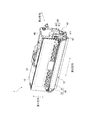
図3は、本実施形態の現像カートリッジ1の斜視図である。図4は、現像カートリッジ1の分解斜視図である。図3および図4に示すように、現像カートリッジ1は、ケーシング10、現像ローラ30、ギア部40、およびICチップアセンブリ60を有する。
<1.2. About
FIG. 3 is a perspective view of the developing
ケーシング10は、一方向に延びる、現像剤を収容可能な筐体である。ケーシング10の第1方向における端部には、現像ローラ30が位置する。現像ローラ30は、第2方向に延びる第1軸について回転可能である。第1方向と、第2方向とは、交差(好ましくは直交)する。現像ローラ30は、第2方向に延びる第1軸について、回転可能である。さらに、後述するICチップ61の電気的接触面611と交差する方向を「第3方向」と称する。第3方向は、第1方向と第2方向とのそれぞれに交差(好ましくは直交)する。なお、第1方向は、現像カートリッジ1をドロアユニット90に挿入する際の挿入方向でもある。
The
ケーシング10は、現像剤を収容する現像剤室12を内部に有する。ケーシング10は開口部13を有する。開口部13は、現像剤室12と外部とを連通する。開口部13は、第1方向におけるケーシング10の一端部に位置する。現像ローラ30は、開口部13に位置する。
The
現像ローラ30は、ローラ本体31と、ローラシャフト32とを有する。ローラ本体31は、第2方向に延びるローラシャフト32に対して、回転不能に固定される。また、ローラシャフト32の第2方向の一方の端部は、後述する現像ギア42に対して、回転不能に固定される。したがって、現像ギア42が回転すると、ローラシャフト32も回転し、ローラシャフト32と共にローラ本体31も回転する。
The developing
現像カートリッジ1が駆動力を受けると、ケーシング10内の現像剤室12から、図示を省略した供給ローラを介して、現像ローラ30の外周面に、現像剤が供給される。その際、供給ローラと現像ローラ30との間において、現像剤は摩擦帯電される。一方、現像ローラ30のローラシャフト32には、バイアス電圧がかけられている。このため、ローラシャフト32と現像剤との間の静電気力によって、ローラ本体31の外周面に、現像剤が引き付けられる。
When the developing
また、現像カートリッジ1は、図示を省略した層厚規制ブレードを有する。層厚規制ブレードは、ローラ本体31の外周面に供給された現像剤を、一定の厚みにする。その後、ローラ本体31の外周面の現像剤は、ドロアユニット90に設けられた感光ドラムへ供給される。このとき、現像剤は、感光ドラムの外周面に形成された静電潜像に応じて、ローラ本体31から感光ドラムへ移動する。これにより、感光ドラムの外周面において、静電潜像が可視像化される。
Further, the developing
ケーシング10は、第2方向の一端部に外表面11を有する。外表面11には、ギア部40およびICチップアセンブリ60が設けられる。ギア部40は、後述のように、ケーシング10とともに第1方向および第3方向に、ICチップアセンブリ60に対して移動可能に、外表面11に設けられる。ICチップアセンブリ60は、ケーシング10およびギア部40に対して、第1方向および第3方向に移動可能に、外表面11に設けられる。つまり、後述のカップリング41は、ケーシング10とともに第1方向および第3方向に、ICチップアセンブリ60に対して移動可能に、外表面11に設けられる。ICチップアセンブリ60は、ケーシング10およびカップリング41に対して、第1方向および第3方向に移動可能に、外表面11に設けられる。
The
ギア部40は、図4に示すように、カップリング41、現像ギア42、アイドルギア43、アジテータギア44、および第1カバー45を有する。なお、各図では、各ギアの複数のギア歯の図示が省略されている。
As shown in FIG. 4, the
カップリング41は、画像形成装置100から供給される駆動力を、最初に受ける部材である。カップリング41は、第2方向に延びる第2軸について回転可能である。カップリング41は締結穴411を有する。締結穴411は、第2方向に凹む凹部である。ケーシング10の外表面11には、カップリングギア412が、第2軸について回転可能に設けられる。カップリング41は、カップリングギア412と共に、第2軸について回転する。カップリング41およびカップリングギア412は、樹脂により一体に形成されてもよいし、別部品であってもよい。
The
現像カートリッジ1が装着されたドロアユニット90が、画像形成装置100に収納されると、画像形成装置100の駆動シャフトが、カップリング41の締結穴411に挿入される。これにより、駆動シャフトとカップリング41とが、回転不能に連結される。したがって、駆動シャフトが回転すると、カップリング41が回転する。そして、カップリング41と共にカップリングギア412も回転する。
When the
現像ギア42は、現像ローラ30を回転させるためのギアである。現像ギア42は、第2方向に延びる第1軸について回転することが可能である。現像ギア42の外周部には、全周に亘って等間隔に複数のギア歯が設けられている。カップリングギア412の複数のギア歯のうちの少なくとも一部のギア歯と、現像ギア42の複数のギア歯のうちの少なくとも一部のギア歯とは、互いに噛み合う。また、現像ギア42は、現像ローラ30のローラシャフト32の第2方向の端部に、回転不能に固定されている。このため、カップリングギア412が回転すると、現像ギア42が回転する。そして、現像ギア42と共に現像ローラ30も回転する。
The developing
アイドルギア43は、カップリングギア412の回転をアジテータギア44に伝達するためギアである。アイドルギア43は、第2方向に延びる回転軸について回転することが可能である。カップリングギア412が回転すると、アイドルギア43が回転する。そして、アイドルギア43の回転に伴い、アジテータギア44も回転する。
The
アジテータギア44は、現像剤室12内のアジテータ20を回転させるためのギアである。アジテータ20は、アジテータシャフト21と撹拌羽根22とを有する。アジテータシャフト21は、第2方向に延びる回転軸に沿って延びる。撹拌羽根22は、アジテータシャフト21から径方向外側へ向けて拡がる。撹拌羽根22は、ケーシング10の現像剤室12内に配置される。アジテータシャフト21の第2方向の端部には、アジテータギア44が連結される。したがって、アジテータシャフト21および撹拌羽根22は、アジテータギア44と共に回転する。撹拌羽根22が回転すると、現像剤室12内の現像剤が撹拌される。
The
アジテータギア44は、第2方向に延びる回転軸について回転することが可能である。アジテータギア44の外周部には、全周に亘って等間隔に複数のギア歯が設けられている。カップリング41からアイドルギア43を介してアジテータギア44に動力が伝達されると、アジテータギア44が回転する。そして、アジテータギア44と共にアジテータ20も回転する。
The
ケーシング10の外表面11には、第1カバー45が、例えばねじ止めで、固定される。カップリングギア412、現像ギア42、アイドルギア43、およびアジテータギア44は、外表面11と第1カバー45との間に収容される。第1カバー45は、第2方向に貫通する貫通孔451を有する。カップリング41の締結穴411は、第1カバー45の貫通孔451を介して、外部に露出する。第1カバー45は、後述するICチップアセンブリ60のICチップホルダ62を保持するホルダカバーを兼ねている。
The
<1.3.ICチップアセンブリについて> <1.3. About IC chip assembly>
ICチップアセンブリ60は、ケーシング10の外表面11に配置され、第1カバー45に保持される。ICチップアセンブリ60は、記憶媒体であるICチップ61と、ICチップ61を保持するICチップホルダ62とを有する。
The
ICチップ61には、現像カートリッジ1に関する種々の情報が記録されている。ICチップ61は、電気的接触面611を有する。電気的接触面611は、導体である金属からなる。ICチップ61は、ICチップホルダ62の第3方向の外表面62Aに固定される。ただし、ICチップホルダ62の外表面62Aには、電気的接触面611のみが固定され、ICチップ61の回路等は他の位置に設けられてもよい。
Various information about the developing
ドロアユニット90は、電気コネクタを有する。電気コネクタは、例えば金属製である。現像カートリッジ1がドロアユニット90に装着されると、電気的接触面611は、ドロアユニット90の電気コネクタに接触する。これにより、画像形成装置100は、ICチップ61からの情報の読み出し、およびICチップ61への情報の書き込みの少なくとも一方を行うことが可能となる。
The
図5は、ICチップアセンブリ60を第2方向から視た図である。図6は、ICチップアセンブリ60を第1方向から視た図である。
FIG. 5 is a view of the
ICチップホルダ62は、第1ホルダ621と、第2ホルダ622と、連結部623と、を有する。第1ホルダ621と、第2ホルダ622とは、第3方向に配列される。連結部623は、第3方向に延びる。第1ホルダ621と、第2ホルダ622とは、連結部623によって連結される。
The
第1ホルダ621は、ICチップ61を保持する外表面62Aを有する。第1ホルダ621は、第2ホルダ622に向けて第3方向に延びる第1連結部623Aを有する。第2ホルダ622は、第1ホルダ621に向けて第3方向に延びる第2連結部623Bを有する。連結部623は、第1連結部623Aと、第2連結部623Bとが、組み合わされることで構成される。例えば、第1連結部623Aは、第2連結部623Bに嵌め込まれると、第2連結部623Bに沿って、第3方向に移動可能となる。これにより、第1ホルダ621は、第2ホルダ622に対して、第3方向に移動可能となる。
The
連結部623は、第3方向のいずれの位置においても、第1方向の長さは同じである。連結部623の第1方向の長さをL1で表す。また、第3方向において、第2ホルダ622と向かい合う部分の第1ホルダ621の第1方向の長さをL2で表す。さらに、第3方向において、第1ホルダ621と向かい合う部分の第2ホルダ622の第1方向の長さをL3で表す。この場合において、長さL1は、長さL2および長さL3よりも短い。長さL1が、長さL2および長さL3よりも短いため、第1ホルダ621と、第2ホルダ622との間であって、連結部623の周囲には、空間64(図5参照)がある。
The connecting
ICチップアセンブリ60は、コイルばね63を有する。コイルばね63は、第1状態と第2状態との間で第3方向に伸縮する弾性部材である。コイルばね63は、第1ホルダ621と、第2ホルダ622との間に配置される。第1ホルダ621は、コイルばね63の伸縮に伴い、第2ホルダ622に対して、第3方向に移動する。連結部623は、第3方向に延びる空洞を有し、コイルばね63は、連結部623の空洞に配置される。
The
コイルばね63の第1状態における第3方向の長さは、コイルばね63の第2状態における第3方向の長さよりも長い。第1状態でのコイルばね63が略自然長である場合、第2状態でのコイルばね63は、自然長よりも収縮している。以下では、コイルばね63が第1状態での、ケーシング10およびカップリング41に対する第1ホルダ621の第3方向の位置を、「初期位置(第3位置)」と称する。また、コイルばね63が第2状態での、ケーシング10およびカップリング41に対する第1ホルダ621の第3方向の位置を、「収縮位置(第4位置)」と称する。第1ホルダ621は、コイルばね63が第2状態のときに収縮位置(第4位置)に位置し、コイルばね63が第1状態のときに初期位置(第3位置)に位置する。
The length of the
このように構成されるICチップアセンブリ60は、ケーシング10の外表面11において、第1カバー45に保持される。第1カバー45は、第3方向に貫通する開口452を有する。ICチップアセンブリ60は、ICチップホルダ62の連結部623(第1連結部623A、および第2連結部623B)が、開口452に挿入されることで、第1カバー45に保持される。
The
第1カバー45の開口452の第1方向の長さは、第1ホルダ621の第1方向の長さ、および第2ホルダ622の第1方向の長さよりも短い。このため、開口452に連結部623が挿入されたICチップアセンブリ60は、第1カバー45から抜け落ちることはない。
The length of the
また、第1カバー45の開口452の第1方向の長さは、連結部623の第1方向の長さよりも長い。このため、第1ホルダ621および第2ホルダ622は、ケーシング10、カップリング41および第1カバー45に対して、第1方向に移動可能となる。
Further, the length of the
現像ローラ30がドロアユニット90に装着される途中で、第1ホルダ621は、第2ホルダ622に向かって移動する。このとき、第2ホルダ622は、ドロアユニット90により、第3方向において、第1ホルダ621の反対方向への移動が妨げられる。第1ホルダ621の移動に伴い、コイルばね63は収縮する。現像ローラ30がドロアユニット90に装着されると、コイルばね63の復元力により、第1ホルダ621は、第3方向において、第2ホルダ622の反対方向へ移動する。電気的接触面611は、ドロアユニット90の電気コネクタに向かって押圧され、電気的接触面611と電気コネクタとが接触し、接触が維持される。
While the developing
また、画像形成装置100は、接触状態と離間状態とを有する。接触状態は、電気的接触面611と電気コネクタとの接触が維持されつつ、現像ローラ30と感光ドラムとが接触する状態である。また、離間状態は、画像形成装置100が、現像ローラ30と感光ドラムとを互いに離れさせる状態である。画像形成装置100は、接触状態と離間状態とのいずれかの状態で動作する。画像形成装置100が離間状態と接触状態との間で変化する場合、電気的接触面611と電気コネクタとの接触が維持された状態で、ケーシング10、カップリング41および第1カバー45は、第1方向に移動する。このため、画像形成装置が離間状態と接触状態との間で変化する場合、ケーシング10、カップリング41および第1カバー45は、ICチップホルダ62に対して、第1方向に移動する。
Further, the
以下、接触状態における、ケーシング10および第1カバー45に対する、ICチップホルダ62の位置を、「第1位置」と称す。また、離間状態における、ケーシング10および第1カバー45に対する、ICチップホルダ62の位置を、「第2位置」と称す。第2位置は、第1位置よりも現像ローラ30の近くに位置する。
Hereinafter, the position of the
前記のように、第1カバー45は、カップリング41が挿入される貫通孔451を有する。開口452と、貫通孔451とは、第1方向に並んで設けられる。つまり、ICチップアセンブリ60と、カップリング41とは、第1方向に並んだ状態で、ICチップアセンブリ60は第1カバー45に取り付けられ、カップリング41の締結穴411は、第1カバー45の貫通孔451から露出される。
As described above, the
図7は、第2方向から現像カートリッジ1の外表面11を視た図である。図7は、第1カバー45を省略した図である。また、図7は、ICチップアセンブリ60が第1位置にある状態を示す。図8は、ICチップホルダ62が第1位置にある場合と、第2位置にある場合とにおける、ICチップホルダ62と、カップリング41との位置関係を示す図である。図8の上図は、ICチップホルダ62が第1位置にある場合、図8の下図は、ICチップホルダ62が第2位置にある場合を示す。
FIG. 7 is a view of the
図7に示すように、ICチップアセンブリ60と、カップリング41とは、第1方向に並んで配置される。また、カップリング41の一部は、第3方向において、第1ホルダ621と第2ホルダ622との間に位置し、かつ、連結部623と第1方向に離れて位置する。つまり、カップリング41の一部は、第1ホルダ621と第2ホルダ622との間の空間64に位置する。これにより、第1ホルダ621および第2ホルダ622と、カップリング41とは、第3方向において重なるため、第1ホルダ621および第2ホルダ622とカップリング41とが占める第1方向の大きさを小型化できる。その結果、現像カートリッジ1を小型化でき、これが装着される画像形成装置100の小型化も実現できる。
As shown in FIG. 7, the
なお、第1ホルダ621が収縮位置にあっても、カップリング41の一部は、空間64に位置することができる。つまり、収縮位置にある第1ホルダ621と、第2ホルダ622との間の第3方向の長さは、空間64に位置するカップリング41の一部の第3方向の長さよりも長い。このため、第1方向において、カップリング41がICチップアセンブリ60に入り込んだ構造であっても、カップリング41と、第1ホルダ621および第2ホルダ622とが、干渉しあうことはない。
Even if the
また、図8の下図に示すように、ICチップホルダ62が第2位置にある場合にも、カップリング41の一部は、第1ホルダ621と第2ホルダ622との間に位置し、その状態で、カップリング41の一部は、連結部623と第1方向に離れて位置する。つまり、カップリング41の一部は、第1ホルダ621と第2ホルダ622との間の空間64に位置する。
Further, as shown in the lower figure of FIG. 8, even when the
つまり、ICチップホルダ62が第1位置および第2位置のいずれに位置していても、第1ホルダ621および第2ホルダ622と、カップリング41とは、第3方向において重なるため、第1ホルダ621および第2ホルダ622とカップリング41とが占める第1方向の大きさを小型化できる。その結果、現像カートリッジ1を小型化できる。
That is, regardless of whether the
なお、ICチップホルダ62が第2位置にあるときのみ、カップリング41の一部が、第1ホルダ621と第2ホルダ622との間の空間64に位置する構成であってもよい。すなわち、ICチップホルダ62が第1位置にある接触状態では、カップリング41の一部は、第1ホルダ621と第2ホルダ622との間の空間64に位置しない。この場合であっても、少なくとも、離間状態時には、第1ホルダ621および第2ホルダ622と、カップリング41とは、第3方向において重なるため、第1ホルダ621および第2ホルダ622とカップリング41とが占める第1方向の大きさを小型化できる。
Only when the
<2.実施形態2>
以下、本発明の実施形態2の現像カートリッジについて説明する。本実施形態では、現像カートリッジを第1方向に小型化するための構造が、実施形態1と相違する。詳しくは、実施形態1のICチップホルダ62は、図5に示す空間64を有しているのに対し、本実施形態のICチップホルダは、空間64を有していない。また、実施形態1のカップリング41は、現像カートリッジの外表面11に設けられ、カップリングギア412と一体形成されているのに対し、本実施形態のカップリング41は、外表面11と第2方向に離れて配置される。そして、第2方向において、カップリング41と、カップリングギア412との間に、ICチップホルダが位置する。
<2.
Hereinafter, the developing cartridge according to the second embodiment of the present invention will be described. In the present embodiment, the structure for miniaturizing the developing cartridge in the first direction is different from that in the first embodiment. Specifically, the
図9は、本実施形態の現像カートリッジ2の斜視図である。図10は、現像カートリッジ2の分解斜視図である。
FIG. 9 is a perspective view of the developing
カップリング41は、図10に示すように、外表面11から、第2方向に離れて配置される。カップリングギア412は、外表面11に回転可能である。つまり、カップリング41と、カップリングギア412とは、第2方向に離れて位置する。
As shown in FIG. 10, the
カップリング41は、カップリングギア412に向かって、第2方向に延びるシャフト軸413を有する。シャフト軸413は、カップリング41とカップリングギア412とを連結する。そして、カップリングギア412は、カップリング41と共に回転する。カップリング41、カップリングギア412およびシャフト軸413は、別部品であってもよいし、一体形成されていてもよい。
The
シャフト軸413は、円柱形状である。シャフト軸413の外径は、カップリング41およびカップリングギア412それぞれの外径よりも小さい。なお、カップリングギア412の外径は、ギア歯を除く径であってもよいし、ギア歯を含む円周の外径であってもよい。少なくとも、カップリング41と、カップリングギア412との間であって、シャフト軸413の周囲に、空間が形成されればよい。
The
ICチップアセンブリ60のICチップホルダ65は、第1ホルダ651と、第2ホルダ652と、を有する。本実施形態のICチップホルダ65は、実施形態1の連結部623を有さない。第1ホルダ651と、第2ホルダ652とは、連結部623を介することなく、着脱不可に、直接組み合わされる。また、第1ホルダ651は、第2ホルダ52に対して、第3方向に移動可能である。
The
第1ホルダ651は、第3方向に延びる円筒状の保持部651Aを有する。第2ホルダ652も、第3方向に延びる円筒状の保持部652Aを有する。保持部651Aの内径は、保持部652Aの外径よりも大きく、保持部651Aの内側に、保持部652Aが挿入可能である。また、保持部652Aの内径は、コイルばね63の外径よりも大きく、コイルばね63は、保持部651A、652Aの内部に収容可能である。コイルばね63は、少なくとも自然長よりも短い状態で、保持部651A、652Aの内部に収容される。第1ホルダ651が、第2ホルダ652に向かって第3方向に移動すると、第1ホルダ651は、コイルばね63を収縮する。また、第1ホルダ651は、コイルばね63の復元力により、第3方向において、第2ホルダ652の反対方向に移動する。
The
第1ホルダ651は、第2方向に貫通する開口651Bを有する。シャフト軸413は、この開口651Bに挿入される。つまり、カップリング41と、カップリングギア412とは、シャフト軸413が開口651Bに挿入された状態で、第1ホルダ651で保持される。そして、カップリング41が、第1カバー45の貫通孔451に挿入された状態で、ICチップホルダ65は、第1カバー45と外表面11とに挟まれて保持される。
The
第1ホルダ651の開口651Bの第1方向および第3方向の内径は、シャフト軸413の外径よりも大きく、かつ、カップリング41およびカップリングギア412それぞれの外径よりも小さい。これにより、第1ホルダ651は、カップリング41およびカップリングギア412に対して、第1方向および第3方向に、移動可能となる。この結果、第1ホルダ651は、コイルばね63の伸縮に伴い、第2ホルダ652に対して、第3方向に移動可能となる。また、画像形成装置100は、現像ローラ30と感光ドラムとが接触する接触状態と、現像ローラ30と感光ドラムとが互いに離れた離間状態とのいずれかの状態での動作が可能となる。
The inner diameters of the
図11は、第2方向から現像カートリッジ2の外表面11を視た図である。図11は、第1カバー45を省略した図である。
FIG. 11 is a view of the
図11に示すように、ICチップアセンブリ60と、カップリング41とは、第1方向に並んで配置される。また、シャフト軸413が、第1ホルダ651の開口651Bに挿入されることで、カップリング41の一部は、第3方向において、第1ホルダ651と第2ホルダ622との間に位置する。シャフト軸413が第1ホルダ651の開口651Bに挿入されるため、ICチップホルダ65が第1位置および第2位置のいずれにあっても、カップリング41の一部は、第3方向において、第1ホルダ651と第2ホルダ652との間に位置する。
As shown in FIG. 11, the
これにより、第1ホルダ651および第2ホルダ652と、カップリング41とは、第3方向において重なるため、第1ホルダ651および第2ホルダ652とカップリング41とが占める第1方向の大きさを小型化できる。その結果、現像カートリッジ2を小型化できる。
As a result, the
<3.1.実施形態3>
以下、本発明の実施形態3の現像カートリッジについて説明する。実施形態3と、実施形態2とは、第1ホルダまたは第2ホルダに、第2方向に貫通する穴を設けて、その穴にカップリングを挿入する点で共通している。しかしながら、実施形態2では、カップリング41の一部は、第1ホルダと第2ホルダとの間に位置しているが、実施形態3では、カップリング41の一部は、第1ホルダ内または第2ホルダ内に位置している。
<3.1. Embodiment 3>
Hereinafter, the developing cartridge according to the third embodiment of the present invention will be described. The third embodiment and the second embodiment are common in that the first holder or the second holder is provided with a hole penetrating in the second direction, and the coupling is inserted into the hole. However, in the second embodiment, a part of the
図12は、実施形態3の現像カートリッジのICチップホルダ65およびカップリング41の斜視図である。図13は、図12のICチップホルダ65およびカップリング41を、第2方向から視た図である。
FIG. 12 is a perspective view of the
カップリング41は、第2方向に延びる円筒状である。カップリング41の第2方向の一方端には、第2方向に凹んだ締結穴411(凹部)が設けられる。また、カップリング41の第2方向の他方端は、カップリングギア412に接続される。そして、カップリング41は、カップリングギア412とともに回転する。カップリング41およびカップリングギア412は、別部品であってもよいし、一体形成されていてもよい。
The
ICチップアセンブリ60のICチップホルダ65は、実施形態2と同様に、第1ホルダ651と、第2ホルダ652と、を有する。第1ホルダ651は、第2ホルダ52に対して、第3方向に移動可能である。また、第1ホルダ651は、第3方向に延びる円筒状の保持部651Aを有する。第2ホルダ652も、第3方向に延びる円筒状の保持部652Aを有する。保持部651Aと、保持部652Aとは、第3方向に並んで配置される。コイルばね63は、その保持部651A、652Aの内部に収容される。第1ホルダ651は、コイルばね63の伸縮に伴い、第2ホルダ652に対して、第3方向に移動する。
The
第1ホルダ651は、第2方向に貫通する貫通孔651Cを有する。カップリング41は、貫通孔651Cに挿入される。貫通孔651Cの第1方向および第3方向の長さは、カップリング41の外径よりも長い。これにより、カップリング41が貫通孔651Cに挿入された状態で、第1ホルダ651と、第2ホルダ652とは、ケーシング10およびカップリング41に対して、第1方向および第3方向に移動可能となる。また、第1ホルダ651は、コイルばね63の伸縮に伴い、第2ホルダ652に対して、接触位置(第3位置)と中間位置(第4位置)との間で、第3方向に移動可能となる。
The
以上のように、第1ホルダ651および第2ホルダ652と、カップリング41とは、第3方向において重なるため、第1ホルダ651および第2ホルダ652とカップリング41とが占める第1方向の大きさを小型化できる。その結果、現像カートリッジを小型化できる。また、カップリング41は、第1ホルダ651の貫通孔651Cに挿入されるため、さらに、第2方向においても、現像カートリッジを小型化することができる。
As described above, since the
<3.2.実施形態3の変形例>
実施形態3では、第1ホルダ651にカップリング41が挿入される貫通孔を設けているが、第2ホルダ652に貫通孔を設けてもよい。実施形態3の変形例の変形例として、第2ホルダ652に、カップリング41を挿入する貫通孔を設けた構成について説明する。
<3.2. Modification of Embodiment 3>
In the third embodiment, the
図14は、第2ホルダ652内にカップリング41が位置する場合の、ICチップホルダ65およびカップリング41の斜視図である。図15は、図14のICチップホルダ65およびカップリング41を、第2方向から視た図である。
FIG. 14 is a perspective view of the
この例では、第2ホルダ652に、第2方向に貫通する貫通孔652Bが設けられる。カップリング41は、貫通孔652Bに挿入される。貫通孔652Bの第1方向および第3方向の長さは、カップリング41の外径よりも長い。これにより、図12および図13の構成と同様に、カップリング41が貫通孔652Bに挿入された状態で、第1ホルダ651と、第2ホルダ652とは、ケーシング10およびカップリング41に対して、第1方向および第3方向に移動可能となる。また、第1ホルダ651は、コイルばね63の伸縮に伴い、第2ホルダ652に対して、接触位置(第3位置)と中間位置(第4位置)との間で、第3方向に移動可能となる。
In this example, the
また、第1ホルダ651および第2ホルダ652は、本実施形態の構成に限定されない。図16は、実施形態3の別の例のICチップホルダ65およびカップリング41の斜視図である。図17は、図16を、第2方向から視た図である。図16および図17では、図14および図15のICチップホルダ65と同様に、第2ホルダ652に、第2方向に貫通する貫通孔652Cが設けられる。貫通孔652Cの第1方向および第3方向の長さは、カップリング41の外径よりも大きい。この貫通孔652Bにカップリング41が挿入される。これにより、カップリング41が貫通孔652Cに挿入された状態で、第1ホルダ651と、第2ホルダ652とは、ケーシング10およびカップリング41に対して、第1方向および第3方向に移動可能となる。
Further, the
<4.その他の変形例>
以上、本発明の実施形態について説明したが、本発明は、上記の実施形態に限定されるものではない。
<4. Other variants>
Although the embodiments of the present invention have been described above, the present invention is not limited to the above embodiments.
例えば、現像カートリッジを第1方向に小型化するための構造は、上記の内容に限定されない。 For example, the structure for miniaturizing the developing cartridge in the first direction is not limited to the above contents.
図18および図19は、変形例1について、現像カートリッジを第1方向に小型化するための構造を示す図である。図18および図19は、ICチップホルダ65と、カップリング41とを示し、現像カートリッジ1の他の部材は省略している。
18 and 19 are views showing a structure for miniaturizing the developing cartridge in the first direction with respect to the first modification. 18 and 19 show the
変形例1のICチップホルダ65は、実施形態2と同様に、第1ホルダ651と第2ホルダ652とを有する。ただし、変形例1の第1ホルダ651は、図10に示す開口651Bを有さない。
The
変形例1のカップリング41は、実施形態2と同様に、カップリングギア412に向かって、第2方向に延びるシャフト軸413を有する。カップリング41は、シャフト軸413を介して、カップリングギア412に連結される。カップリング41と、カップリングギア412との間の長さは、ICチップホルダ65の第2方向の長さよりも長い。ICチップホルダ65は、カップリング41と、カップリングギア412との間に位置する。
The
このような構成であっても、第1ホルダ651および第2ホルダ652と、カップリング41とは、第3方向において重なるため、第1ホルダ651および第2ホルダ652とカップリング41とが占める第1方向の大きさを小型化できる。
Even with such a configuration, since the
また、現像カートリッジを第1方向に小型化するために、実施形態1のICチップホルダ62と、実施形態2のカップリング41およびシャフト軸413の構成とを組み合わせた構造としてもよい。
Further, in order to reduce the size of the developing cartridge in the first direction, the structure may be a combination of the
図20および図21は、変形例2のICチップホルダ62と、カップリング41との位置関係を示す図である。
20 and 21 are diagrams showing the positional relationship between the
変形例2では、カップリング41は、実施形態2と同様に、シャフト軸413を介して、カップリングギア412と連結する。シャフト軸413が、ICチップホルダ62の空間64に位置することで、カップリング41の一部は、第1ホルダ621と第2ホルダ622との間に位置する。シャフト軸413を空間64に位置させることで、実施形態1と比べて、第1方向において、ICチップホルダ62に、カップリング41をより近くに配置させることができる。その結果、実施形態1と比べて、第1ホルダ621および第2ホルダ622とカップリング41とが占める第1方向の大きさをさらに小型化できる。
In the second modification, the
上記の実施形態では、弾性部材としてコイルばね63が用いられていた。しかしながら、コイルばね63に代えて、板ばね、トーションばねなどの他の種類のばねが用いられてもよい。
In the above embodiment, the
また、上記の実施形態では、第1ホルダの外表面に、電気的接触面611を有するICチップ61が固定されていた。しかしながら、第1ホルダの外表面には、電気コネクタと接触する電気的接触面のみを固定し、ICチップの電気的接触面以外の部分は、現像カートリッジの他の箇所に配置されていてもよい。
Further, in the above embodiment, the
また、上記の実施形態または変形例に登場した各要素を、矛盾が生じない範囲で、適宜に組み合わせてもよい。 In addition, each element appearing in the above-described embodiment or modification may be appropriately combined as long as there is no contradiction.
1 :現像カートリッジ
2 :現像カートリッジ
10 :ケーシング
11 :外表面
12 :現像剤室
13 :開口部
20 :アジテータ
21 :アジテータシャフト
22 :撹拌羽根
30 :現像ローラ
31 :ローラ本体
32 :ローラシャフト
40 :ギア部
41 :カップリング
42 :現像ギア
43 :アイドルギア
44 :アジテータギア
45 :第1カバー52 :第2ホルダ
60 :ICチップアセンブリ
61 :ICチップ
62 :ICチップホルダ
62A :外表面
63 :コイルばね
64 :空間
65 :ホルダ
80 :制御部
90 :ドロアユニット
91 :スロット
100 :画像形成装置
411 :締結穴
412 :カップリングギア
413 :シャフト軸
451 :貫通孔
452 :開口
611 :電気的接触面
621 :第1ホルダ
622 :第2ホルダ
623 :連結部
623A :第1連結部
623B :第2連結部
651 :第1ホルダ
651A :保持部
651B :開口
652 :第2ホルダ
652A :保持部
1: Development cartridge 2: Development cartridge 10: Casing 11: Outer surface 12: Developer chamber 13: Opening 20: Agitator 21: Agitator shaft 22: Stirring blade 30: Development roller 31: Roller body 32: Roller shaft 40: Gear Part 41: Coupling 42: Developing gear 43: Idle gear 44: Agitator gear 45: First cover 52: Second holder 60: IC chip assembly 61: IC chip 62:
Claims (20)
第1方向における前記筐体の端部に位置する現像ローラであって、第2方向に延びる第1軸について回転可能な現像ローラと、
電気的接触面を有する記憶媒体と、
前記筐体に対して、前記第1方向に移動可能な第1ホルダであって、外表面に前記電気的接触面を保持する第1ホルダと、
前記筐体に対して前記第1方向に、前記第1ホルダと共に移動可能な第2ホルダであって、前記電気的接触面に交差する第3方向について、前記第1ホルダと離れて位置する第2ホルダと、
前記第2方向に延びる第2軸について回転可能なカップリングであって、前記現像ローラと共に回転可能なカップリングと、
を備え、
前記第1ホルダと前記第2ホルダとは、
前記筐体および前記カップリングに対して、前記第1方向における第1位置と、前記第1方向における第2位置であって、前記第1位置よりも前記現像ローラの近くに位置する第2位置との間で移動可能であり、
前記第1ホルダと前記第2ホルダが前記第2位置の場合、前記カップリングの一部は、前記第1ホルダと前記第2ホルダとの間に位置する、
ことを特徴とする現像カートリッジ。 A housing that can accommodate the developer and
A developing roller located at the end of the housing in the first direction and rotatable about a first axis extending in the second direction.
A storage medium with an electrical contact surface and
A first holder that is movable in the first direction with respect to the housing and that holds the electrical contact surface on the outer surface.
A second holder that is movable with respect to the housing in the first direction together with the first holder and is located away from the first holder in a third direction that intersects the electrical contact surface. 2 holders and
A coupling that is rotatable about a second axis extending in the second direction and that can rotate with the developing roller.
With
The first holder and the second holder are
A first position in the first direction and a second position in the first direction with respect to the housing and the coupling, which are located closer to the developing roller than the first position. Can be moved to and from
When the first holder and the second holder are in the second position, a part of the coupling is located between the first holder and the second holder.
A developing cartridge characterized by that.
前記第1ホルダと前記第2ホルダとの間に位置する弾性部材であって、第1状態と第2状態との間で前記第3方向に伸縮可能であり、前記第1状態における前記第3方向の長さは、前記第2状態における前記第3方向の長さよりも長い弾性部材
を備え、
前記第1ホルダは、
前記弾性部材の伸縮に伴い、前記第2ホルダに対して、第3位置と第4位置との間で前記第3方向に移動可能であり、前記弾性部材が前記第1状態のときに、前記第1ホルダは前記第3位置に位置し、前記弾性部材が前記第2状態のときに、前記第4位置に位置する、
ことを特徴とする現像カートリッジ。 The developing cartridge according to claim 1.
An elastic member located between the first holder and the second holder, which can expand and contract in the third direction between the first state and the second state, and the third in the first state. The length in the direction includes an elastic member longer than the length in the third direction in the second state.
The first holder is
As the elastic member expands and contracts, it can move in the third direction between the third position and the fourth position with respect to the second holder, and when the elastic member is in the first state, the said The first holder is located at the third position, and is located at the fourth position when the elastic member is in the second state.
A developing cartridge characterized by that.
前記第1ホルダおよび前記第2ホルダが前記第1位置にある場合、前記カップリングの一部が、前記第1ホルダと前記第2ホルダとの間に位置する、
ことを特徴とする現像カートリッジ。 The developing cartridge according to claim 1 or 2.
When the first holder and the second holder are in the first position, a part of the coupling is located between the first holder and the second holder.
A developing cartridge characterized by that.
前記第3方向に延び、前記第1ホルダと前記第2ホルダとを連結する連結部であって、前記第1方向の長さが前記第1ホルダおよび前記第2ホルダよりも短い連結部
を備え、
前記第1ホルダと前記第2ホルダが前記第2位置の場合、前記カップリングの一部が前記第1ホルダと前記第2ホルダとの間に位置する状態で、前記カップリングの一部は、前記連結部と離れて位置する、
ことを特徴とする現像カートリッジ。 The developing cartridge according to any one of claims 1 to 3.
A connecting portion that extends in the third direction and connects the first holder and the second holder, and includes a connecting portion whose length in the first direction is shorter than that of the first holder and the second holder. ,
When the first holder and the second holder are in the second position, a part of the coupling is located between the first holder and the second holder, and a part of the coupling is formed. Located away from the connection
A developing cartridge characterized by that.
前記第1ホルダと前記第2ホルダが前記第1位置の場合、前記カップリングの一部が前記第1ホルダと前記第2ホルダとの間に位置する状態で、前記カップリングの一部は、前記連結部と離れて位置する、
ことを特徴とする現像カートリッジ。 The developing cartridge according to claim 4.
When the first holder and the second holder are in the first position, a part of the coupling is located between the first holder and the second holder, and a part of the coupling is formed. Located away from the connection
A developing cartridge characterized by that.
前記カップリングは、前記第2方向における前記筐体の外表面から、前記第2方向に離れて位置し、
前記現像カートリッジは、さらに、
前記筐体の前記外表面に位置し、前記現像ローラと共に回転可能な現像ローラギアと、
前記現像ローラギアと噛み合うカップリングギアと、
前記第2方向に延びるシャフト軸であって、前記カップリングと前記カップリングギアとを連結するシャフト軸と、
を備え、
前記シャフト軸の径は、前記カップリングの径および前記カップリングギアの径より短く、
前記カップリングと前記カップリングギアとの間に、前記第1ホルダおよび前記第2ホルダの一部が位置することで、前記カップリングの一部が、前記第1ホルダと前記第2ホルダとの間に位置する、
ことを特徴とする現像カートリッジ。
The developing cartridge according to any one of claims 1 to 3.
The coupling is located in the second direction away from the outer surface of the housing in the second direction.
The developing cartridge further
A developing roller gear located on the outer surface of the housing and rotating together with the developing roller,
A coupling gear that meshes with the developing roller gear,
A shaft shaft extending in the second direction, the shaft shaft connecting the coupling and the coupling gear, and
With
The diameter of the shaft shaft is shorter than the diameter of the coupling and the diameter of the coupling gear.
By locating a part of the first holder and the second holder between the coupling and the coupling gear, a part of the coupling is formed between the first holder and the second holder. Located in between,
A developing cartridge characterized by that.
前記第1ホルダおよび前記第2ホルダの一方は、前記第2方向に貫通する開口を有し、
前記シャフト軸が前記開口に挿入されることで、前記カップリングの一部が、前記第1ホルダと前記第2ホルダとの間に位置する、
ことを特徴とする現像カートリッジ。 The developing cartridge according to claim 6.
One of the first holder and the second holder has an opening penetrating in the second direction.
By inserting the shaft shaft into the opening, a part of the coupling is located between the first holder and the second holder.
A developing cartridge characterized by that.
前記第3方向に延び、前記第1ホルダと前記第2ホルダとを連結する連結部であって、前記第1方向の長さが前記第1ホルダおよび前記第2ホルダよりも短い連結部、
を備え、
前記第1ホルダと前記第2ホルダが前記第2位置の場合、前記カップリングの一部が前記第1ホルダと前記第2ホルダとの間に位置する状態で、前記シャフト軸は、前記連結部と離れて位置する、
ことを特徴とする現像カートリッジ。 The developing cartridge according to claim 6.
A connecting portion extending in the third direction and connecting the first holder and the second holder, the length of the first holder being shorter than that of the first holder and the second holder.
With
When the first holder and the second holder are in the second position, the shaft shaft is connected to the connecting portion in a state where a part of the coupling is located between the first holder and the second holder. Located away from,
A developing cartridge characterized by that.
前記第1ホルダと前記第2ホルダが前記第1位置の場合、前記カップリングの一部が前記第1ホルダと前記第2ホルダとの間に位置する状態で、前記シャフト軸は、前記連結部と離れて位置する、
ことを特徴とする現像カートリッジ。 The developing cartridge according to claim 8.
When the first holder and the second holder are in the first position, the shaft shaft is connected to the connecting portion in a state where a part of the coupling is located between the first holder and the second holder. Located away from,
A developing cartridge characterized by that.
前記第1ホルダおよび前記第2ホルダの一方は、
前記第2方向に貫通する開口であって、第1方向および第2方向の長さが、前記カップリングの外径よりも長い開口を有し、
前記カップリングが前記開口に挿入されることで、前記カップリングが、前記第1ホルダと前記第2ホルダとの間に位置する、
ことを特徴とする現像カートリッジ。 The developing cartridge according to any one of claims 1 to 3.
One of the first holder and the second holder
An opening penetrating in the second direction, the opening having a length in the first direction and the second direction longer than the outer diameter of the coupling.
By inserting the coupling into the opening, the coupling is located between the first holder and the second holder.
A developing cartridge characterized by that.
第1方向における前記筐体の端部に位置する現像ローラであって、第2方向に延びる第1軸について回転可能な現像ローラと、
電気的接触面を有する記憶媒体と、
前記筐体に対して、前記第1方向に移動可能な第1ホルダであって、外表面に前記電気的接触面を保持する第1ホルダと、
前記筐体に対して前記第1方向に、前記第1ホルダと共に移動可能な第2ホルダであって、前記電気的接触面に交差する第3方向について、前記第1ホルダと離れて位置する第2ホルダと、
前記第2方向に延びる第2軸について回転可能なカップリングであって、前記現像ローラと共に回転可能なカップリングと、
を備え、
前記第1ホルダと前記第2ホルダのいずれかは、前記第2方向に貫通した貫通孔を有し、
前記カップリングが前記貫通孔に挿入された状態で、前記第1ホルダと前記第2ホルダとは、前記筐体および前記カップリングに対して前記第1方向に移動可能である
ことを特徴とする現像カートリッジ。 A housing that can accommodate the developer and
A developing roller located at the end of the housing in the first direction and rotatable about a first axis extending in the second direction.
A storage medium with an electrical contact surface and
A first holder that is movable in the first direction with respect to the housing and that holds the electrical contact surface on the outer surface.
A second holder that is movable with respect to the housing in the first direction together with the first holder and is located away from the first holder in a third direction that intersects the electrical contact surface. 2 holders and
A coupling that is rotatable about a second axis extending in the second direction and that can rotate with the developing roller.
With
Either the first holder or the second holder has a through hole penetrating in the second direction.
With the coupling inserted into the through hole, the first holder and the second holder can move in the first direction with respect to the housing and the coupling. Development cartridge.
前記第1ホルダと前記第2ホルダとは、
前記筐体および前記カップリングに対して、前記第1方向における第1位置と、前記第1方向における第2位置であって、前記第1位置よりも前記現像ローラの近くに位置する第2位置との間で移動可能である、
ことを特徴とする現像カートリッジ。 The developing cartridge according to claim 11.
The first holder and the second holder are
A first position in the first direction and a second position in the first direction with respect to the housing and the coupling, which are located closer to the developing roller than the first position. Can be moved to and from
A developing cartridge characterized by that.
前記第1ホルダと前記第2ホルダとの間に位置する弾性部材であって、第1状態と第2状態との間で前記第3方向に伸縮可能であり、前記第1状態における前記第3方向の長さは、前記第2状態における前記第3方向の長さよりも長い弾性部材
を備え、
前記第1ホルダは、
前記弾性部材の伸縮に伴い、前記第2ホルダに対して、第3位置と第4位置との間で前記第3方向に移動可能であり、前記弾性部材が前記第1状態のときに、前記第1ホルダは前記第3位置に位置し、前記弾性部材が前記第2状態のときに、前記第4位置に位置する、
ことを特徴とする現像カートリッジ。 The developing cartridge according to claim 11 or 12.
An elastic member located between the first holder and the second holder, which can expand and contract in the third direction between the first state and the second state, and the third in the first state. The length in the direction includes an elastic member longer than the length in the third direction in the second state.
The first holder is
As the elastic member expands and contracts, it can move in the third direction between the third position and the fourth position with respect to the second holder, and when the elastic member is in the first state, the said The first holder is located at the third position, and is located at the fourth position when the elastic member is in the second state.
A developing cartridge characterized by that.
第1方向における前記筐体の端部に位置する現像ローラであって、第2方向に延びる第1軸について回転可能な現像ローラと、
電気的接触面を有する記憶媒体と、
前記筐体に対して、前記第1方向に移動可能な第1ホルダであって、外表面に前記電気的接触面を保持する第1ホルダと、
前記筐体に対して前記第1方向に、前記第1ホルダと共に移動可能な第2ホルダであって、前記電気的接触面に交差する第3方向について、前記第1ホルダと離れて位置する第2ホルダと、
前記第2方向に延びる第2軸について回転可能なカップリングであって、前記現像ローラと共に回転可能なカップリングと、
前記第1ホルダと前記第2ホルダとの間に位置する弾性部材であって、第1状態と第2状態との間で前記第3方向に伸縮可能であり、前記第1状態における前記第3方向の長さは、前記第2状態における前記第3方向の長さよりも長い弾性部材と、
を備え、
前記第1ホルダと前記第2ホルダのいずれかは、前記第2方向に貫通した貫通孔を有し、
前記カップリングが前記貫通孔に挿入された状態で、前記第1ホルダは、前記弾性部材の伸縮に伴い、前記第2ホルダに対して、第3位置と第4位置との間で前記第3方向に移動可能であり、
前記第1ホルダは、前記弾性部材が前記第1状態のときに、前記第3位置に位置し、前記弾性部材が前記第2状態のときに、前記第4位置に位置する、
ことを特徴とする現像カートリッジ。 A housing that can accommodate the developer and
A developing roller located at the end of the housing in the first direction and rotatable about a first axis extending in the second direction.
A storage medium with an electrical contact surface and
A first holder that is movable in the first direction with respect to the housing and that holds the electrical contact surface on the outer surface.
A second holder that is movable with respect to the housing in the first direction together with the first holder and is located away from the first holder in a third direction that intersects the electrical contact surface. 2 holders and
A coupling that is rotatable about a second axis extending in the second direction and that can rotate with the developing roller.
An elastic member located between the first holder and the second holder, which can expand and contract in the third direction between the first state and the second state, and the third in the first state. The length in the direction is longer than the length in the third direction in the second state, and the elastic member
With
Either the first holder or the second holder has a through hole penetrating in the second direction.
With the coupling inserted into the through hole, the first holder moves between the third position and the fourth position with respect to the second holder as the elastic member expands and contracts. Movable in the direction,
The first holder is located at the third position when the elastic member is in the first state, and is located at the fourth position when the elastic member is in the second state.
A developing cartridge characterized by that.
前記第1ホルダが前記貫通孔を有する
ことを特徴とする現像カートリッジ。 The developing cartridge according to any one of claims 11 to 14.
A developing cartridge in which the first holder has the through hole.
前記第2ホルダが前記貫通孔を有する
ことを特徴とする現像カートリッジ。 The developing cartridge according to any one of claims 11 to 14.
A developing cartridge in which the second holder has the through hole.
前記カップリングは、前記第2方向に凹む凹部を有する
ことを特徴とする現像カートリッジ。 The developing cartridge according to any one of claims 11 to 16.
The coupling is a developing cartridge having a recess recessed in the second direction.
前記カップリングは、駆動力を受けることが可能であり、
前記カップリングが受けた駆動力に基づいて、前記現像ローラは回転する
ことを特徴とする現像カートリッジ。 The developing cartridge according to any one of claims 1 to 17.
The coupling can receive a driving force and
A developing cartridge characterized in that the developing roller rotates based on the driving force received by the coupling.
前記現像ローラと共に回転可能な現像ローラギアを備え、
前記カップリングは、さらに、
前記現像ローラギアと噛み合うカップリングギアであって、前記カップリングと共に回転可能なカップリングギアを備える
ことを特徴とする現像カートリッジ。 The developing cartridge according to any one of claims 1 to 18.
A developing roller gear that can rotate with the developing roller is provided.
The coupling further
A developing cartridge that is a coupling gear that meshes with the developing roller gear and includes a coupling gear that can rotate together with the coupling.
前記記憶媒体は、前記第1ホルダの前記外表面に位置する、ことを特徴とする現像カートリッジ。
The developing cartridge according to any one of claims 1 to 19.
A developing cartridge characterized in that the storage medium is located on the outer surface of the first holder.
Priority Applications (5)
| Application Number | Priority Date | Filing Date | Title |
|---|---|---|---|
| JP2017122904A JP6958021B2 (en) | 2017-06-23 | 2017-06-23 | Development cartridge |
| CN201880000555.2A CN109429512B (en) | 2017-06-23 | 2018-03-27 | Developing box |
| US15/936,612 US10234818B2 (en) | 2017-06-23 | 2018-03-27 | Developing cartridge having arrangement of chip holder and coupling to provide compact cartridge |
| EP18714421.7A EP3447586B1 (en) | 2017-06-23 | 2018-03-27 | Developing cartridge |
| PCT/JP2018/012300 WO2018235375A1 (en) | 2017-06-23 | 2018-03-27 | Developing cartridge |
Applications Claiming Priority (1)
| Application Number | Priority Date | Filing Date | Title |
|---|---|---|---|
| JP2017122904A JP6958021B2 (en) | 2017-06-23 | 2017-06-23 | Development cartridge |
Publications (2)
| Publication Number | Publication Date |
|---|---|
| JP2019008101A JP2019008101A (en) | 2019-01-17 |
| JP6958021B2 true JP6958021B2 (en) | 2021-11-02 |
Family
ID=63174171
Family Applications (1)
| Application Number | Title | Priority Date | Filing Date |
|---|---|---|---|
| JP2017122904A Active JP6958021B2 (en) | 2017-06-23 | 2017-06-23 | Development cartridge |
Country Status (5)
| Country | Link |
|---|---|
| US (1) | US10234818B2 (en) |
| EP (1) | EP3447586B1 (en) |
| JP (1) | JP6958021B2 (en) |
| CN (1) | CN109429512B (en) |
| WO (1) | WO2018235375A1 (en) |
Families Citing this family (4)
| Publication number | Priority date | Publication date | Assignee | Title |
|---|---|---|---|---|
| JP7154587B2 (en) * | 2019-01-21 | 2022-10-18 | 株式会社ユニバーサルエンターテインメント | game machine |
| JP7205346B2 (en) * | 2019-03-28 | 2023-01-17 | ブラザー工業株式会社 | developer cartridge |
| JP7331411B2 (en) * | 2019-03-28 | 2023-08-23 | ブラザー工業株式会社 | developer cartridge |
| JP2021162755A (en) | 2020-04-01 | 2021-10-11 | ブラザー工業株式会社 | Cartridge and method for recycling cartridge |
Family Cites Families (18)
| Publication number | Priority date | Publication date | Assignee | Title |
|---|---|---|---|---|
| JPH09190058A (en) * | 1996-01-09 | 1997-07-22 | Canon Inc | Process cartridge, developing device and electrophotographic image forming device |
| JP4665927B2 (en) * | 2007-03-27 | 2011-04-06 | ブラザー工業株式会社 | Cartridge and image forming apparatus |
| JP4968301B2 (en) | 2009-09-11 | 2012-07-04 | ブラザー工業株式会社 | Image forming apparatus and tandem photoreceptor unit |
| CN104076672B (en) * | 2010-06-11 | 2020-10-09 | 株式会社理光 | Information storage device, detachable device, developer container, and image forming apparatus |
| JP5884343B2 (en) | 2011-08-31 | 2016-03-15 | ブラザー工業株式会社 | Process cartridge and developer cartridge |
| JP5250139B2 (en) * | 2012-07-06 | 2013-07-31 | 株式会社沖データ | Image forming apparatus |
| JP6375609B2 (en) * | 2012-10-19 | 2018-08-22 | 株式会社リコー | Detachable device and image forming apparatus |
| JP6136374B2 (en) * | 2013-03-04 | 2017-05-31 | ブラザー工業株式会社 | Developer cartridge |
| JP5894965B2 (en) * | 2013-05-21 | 2016-03-30 | 京セラドキュメントソリューションズ株式会社 | Image forming apparatus and toner container |
| US9261851B2 (en) * | 2013-11-20 | 2016-02-16 | Lexmark International, Inc. | Positional control features of a replaceable unit for an electrophotographic image forming device |
| JP6091439B2 (en) * | 2014-01-24 | 2017-03-08 | 京セラドキュメントソリューションズ株式会社 | Image forming apparatus |
| KR20150106729A (en) * | 2014-03-12 | 2015-09-22 | 삼성전자주식회사 | Cartridge and electrophotographic image forming apparatus using the same |
| KR101580224B1 (en) | 2014-03-12 | 2015-12-24 | 삼성전자주식회사 | Cartridge and electrophotographic image forming apparatus using the same |
| CN203982082U (en) * | 2014-05-30 | 2014-12-03 | 珠海艾派克微电子有限公司 | A kind of end cap, cartridge and electrophotographic image generate equipment |
| JP6582972B2 (en) * | 2015-12-25 | 2019-10-02 | ブラザー工業株式会社 | Developer cartridge |
| JP6776567B2 (en) * | 2016-03-18 | 2020-10-28 | ブラザー工業株式会社 | Image forming device |
| JP6907530B2 (en) * | 2016-12-27 | 2021-07-21 | ブラザー工業株式会社 | Image forming device |
| JP6822279B2 (en) * | 2017-03-31 | 2021-01-27 | ブラザー工業株式会社 | Develop cartridges, process cartridges, and image forming equipment |
-
2017
- 2017-06-23 JP JP2017122904A patent/JP6958021B2/en active Active
-
2018
- 2018-03-27 EP EP18714421.7A patent/EP3447586B1/en active Active
- 2018-03-27 WO PCT/JP2018/012300 patent/WO2018235375A1/en active Application Filing
- 2018-03-27 US US15/936,612 patent/US10234818B2/en active Active
- 2018-03-27 CN CN201880000555.2A patent/CN109429512B/en active Active
Also Published As
| Publication number | Publication date |
|---|---|
| EP3447586A1 (en) | 2019-02-27 |
| EP3447586B1 (en) | 2020-04-29 |
| WO2018235375A1 (en) | 2018-12-27 |
| JP2019008101A (en) | 2019-01-17 |
| EP3447586A4 (en) | 2019-02-27 |
| CN109429512B (en) | 2022-07-12 |
| US10234818B2 (en) | 2019-03-19 |
| CN109429512A (en) | 2019-03-05 |
| US20180373195A1 (en) | 2018-12-27 |
Similar Documents
| Publication | Publication Date | Title |
|---|---|---|
| JP6930204B2 (en) | Image forming device | |
| JP6776567B2 (en) | Image forming device | |
| JP6897096B2 (en) | Image forming device | |
| JP6822279B2 (en) | Develop cartridges, process cartridges, and image forming equipment | |
| JP7102774B2 (en) | Development cartridge | |
| JP6958021B2 (en) | Development cartridge | |
| JP6658158B2 (en) | Image forming device | |
| JP7009792B2 (en) | Manufacturing or recycling method | |
| EP3382463B1 (en) | Developing cartridge | |
| JP6907530B2 (en) | Image forming device | |
| JP2021039173A (en) | Drum cartridge | |
| JP2021001948A (en) | Developing cartridge and image forming apparatus | |
| JP7151825B2 (en) | developer cartridge | |
| JP7095362B2 (en) | Drawer | |
| JP6922340B2 (en) | Image forming device | |
| JP2021005112A (en) | Image forming apparatus | |
| JP2023060577A (en) | Image forming apparatus | |
| JP2021113858A (en) | Drawer |
Legal Events
| Date | Code | Title | Description |
|---|---|---|---|
| A621 | Written request for application examination |
Free format text: JAPANESE INTERMEDIATE CODE: A621 Effective date: 20200313 |
|
| A131 | Notification of reasons for refusal |
Free format text: JAPANESE INTERMEDIATE CODE: A131 Effective date: 20210406 |
|
| A521 | Request for written amendment filed |
Free format text: JAPANESE INTERMEDIATE CODE: A523 Effective date: 20210603 |
|
| TRDD | Decision of grant or rejection written | ||
| A01 | Written decision to grant a patent or to grant a registration (utility model) |
Free format text: JAPANESE INTERMEDIATE CODE: A01 Effective date: 20210907 |
|
| A61 | First payment of annual fees (during grant procedure) |
Free format text: JAPANESE INTERMEDIATE CODE: A61 Effective date: 20210920 |
|
| R150 | Certificate of patent or registration of utility model |
Ref document number: 6958021 Country of ref document: JP Free format text: JAPANESE INTERMEDIATE CODE: R150 |