KR101715690B1 - Optical system with movable lens for ophthalmic surgical laser - Google Patents
Optical system with movable lens for ophthalmic surgical laser Download PDFInfo
- Publication number
- KR101715690B1 KR101715690B1 KR1020127002651A KR20127002651A KR101715690B1 KR 101715690 B1 KR101715690 B1 KR 101715690B1 KR 1020127002651 A KR1020127002651 A KR 1020127002651A KR 20127002651 A KR20127002651 A KR 20127002651A KR 101715690 B1 KR101715690 B1 KR 101715690B1
- Authority
- KR
- South Korea
- Prior art keywords
- laser
- scanner
- lens
- aberration
- delivery system
- Prior art date
Links
Images


Classifications
-
- A—HUMAN NECESSITIES
- A61—MEDICAL OR VETERINARY SCIENCE; HYGIENE
- A61F—FILTERS IMPLANTABLE INTO BLOOD VESSELS; PROSTHESES; DEVICES PROVIDING PATENCY TO, OR PREVENTING COLLAPSING OF, TUBULAR STRUCTURES OF THE BODY, e.g. STENTS; ORTHOPAEDIC, NURSING OR CONTRACEPTIVE DEVICES; FOMENTATION; TREATMENT OR PROTECTION OF EYES OR EARS; BANDAGES, DRESSINGS OR ABSORBENT PADS; FIRST-AID KITS
- A61F9/00—Methods or devices for treatment of the eyes; Devices for putting-in contact lenses; Devices to correct squinting; Apparatus to guide the blind; Protective devices for the eyes, carried on the body or in the hand
- A61F9/007—Methods or devices for eye surgery
- A61F9/008—Methods or devices for eye surgery using laser
- A61F9/00825—Methods or devices for eye surgery using laser for photodisruption
- A61F9/0084—Laser features or special beam parameters therefor
-
- A—HUMAN NECESSITIES
- A61—MEDICAL OR VETERINARY SCIENCE; HYGIENE
- A61F—FILTERS IMPLANTABLE INTO BLOOD VESSELS; PROSTHESES; DEVICES PROVIDING PATENCY TO, OR PREVENTING COLLAPSING OF, TUBULAR STRUCTURES OF THE BODY, e.g. STENTS; ORTHOPAEDIC, NURSING OR CONTRACEPTIVE DEVICES; FOMENTATION; TREATMENT OR PROTECTION OF EYES OR EARS; BANDAGES, DRESSINGS OR ABSORBENT PADS; FIRST-AID KITS
- A61F9/00—Methods or devices for treatment of the eyes; Devices for putting-in contact lenses; Devices to correct squinting; Apparatus to guide the blind; Protective devices for the eyes, carried on the body or in the hand
- A61F9/007—Methods or devices for eye surgery
- A61F9/008—Methods or devices for eye surgery using laser
-
- G—PHYSICS
- G02—OPTICS
- G02B—OPTICAL ELEMENTS, SYSTEMS OR APPARATUS
- G02B26/00—Optical devices or arrangements for the control of light using movable or deformable optical elements
- G02B26/08—Optical devices or arrangements for the control of light using movable or deformable optical elements for controlling the direction of light
-
- G—PHYSICS
- G02—OPTICS
- G02F—OPTICAL DEVICES OR ARRANGEMENTS FOR THE CONTROL OF LIGHT BY MODIFICATION OF THE OPTICAL PROPERTIES OF THE MEDIA OF THE ELEMENTS INVOLVED THEREIN; NON-LINEAR OPTICS; FREQUENCY-CHANGING OF LIGHT; OPTICAL LOGIC ELEMENTS; OPTICAL ANALOGUE/DIGITAL CONVERTERS
- G02F1/00—Devices or arrangements for the control of the intensity, colour, phase, polarisation or direction of light arriving from an independent light source, e.g. switching, gating or modulating; Non-linear optics
- G02F1/29—Devices or arrangements for the control of the intensity, colour, phase, polarisation or direction of light arriving from an independent light source, e.g. switching, gating or modulating; Non-linear optics for the control of the position or the direction of light beams, i.e. deflection
-
- A—HUMAN NECESSITIES
- A61—MEDICAL OR VETERINARY SCIENCE; HYGIENE
- A61F—FILTERS IMPLANTABLE INTO BLOOD VESSELS; PROSTHESES; DEVICES PROVIDING PATENCY TO, OR PREVENTING COLLAPSING OF, TUBULAR STRUCTURES OF THE BODY, e.g. STENTS; ORTHOPAEDIC, NURSING OR CONTRACEPTIVE DEVICES; FOMENTATION; TREATMENT OR PROTECTION OF EYES OR EARS; BANDAGES, DRESSINGS OR ABSORBENT PADS; FIRST-AID KITS
- A61F9/00—Methods or devices for treatment of the eyes; Devices for putting-in contact lenses; Devices to correct squinting; Apparatus to guide the blind; Protective devices for the eyes, carried on the body or in the hand
- A61F9/007—Methods or devices for eye surgery
- A61F9/008—Methods or devices for eye surgery using laser
- A61F2009/00844—Feedback systems
- A61F2009/00851—Optical coherence topography [OCT]
-
- A—HUMAN NECESSITIES
- A61—MEDICAL OR VETERINARY SCIENCE; HYGIENE
- A61F—FILTERS IMPLANTABLE INTO BLOOD VESSELS; PROSTHESES; DEVICES PROVIDING PATENCY TO, OR PREVENTING COLLAPSING OF, TUBULAR STRUCTURES OF THE BODY, e.g. STENTS; ORTHOPAEDIC, NURSING OR CONTRACEPTIVE DEVICES; FOMENTATION; TREATMENT OR PROTECTION OF EYES OR EARS; BANDAGES, DRESSINGS OR ABSORBENT PADS; FIRST-AID KITS
- A61F9/00—Methods or devices for treatment of the eyes; Devices for putting-in contact lenses; Devices to correct squinting; Apparatus to guide the blind; Protective devices for the eyes, carried on the body or in the hand
- A61F9/007—Methods or devices for eye surgery
- A61F9/008—Methods or devices for eye surgery using laser
- A61F2009/00861—Methods or devices for eye surgery using laser adapted for treatment at a particular location
- A61F2009/0087—Lens
-
- A—HUMAN NECESSITIES
- A61—MEDICAL OR VETERINARY SCIENCE; HYGIENE
- A61F—FILTERS IMPLANTABLE INTO BLOOD VESSELS; PROSTHESES; DEVICES PROVIDING PATENCY TO, OR PREVENTING COLLAPSING OF, TUBULAR STRUCTURES OF THE BODY, e.g. STENTS; ORTHOPAEDIC, NURSING OR CONTRACEPTIVE DEVICES; FOMENTATION; TREATMENT OR PROTECTION OF EYES OR EARS; BANDAGES, DRESSINGS OR ABSORBENT PADS; FIRST-AID KITS
- A61F9/00—Methods or devices for treatment of the eyes; Devices for putting-in contact lenses; Devices to correct squinting; Apparatus to guide the blind; Protective devices for the eyes, carried on the body or in the hand
- A61F9/007—Methods or devices for eye surgery
- A61F9/008—Methods or devices for eye surgery using laser
- A61F2009/00861—Methods or devices for eye surgery using laser adapted for treatment at a particular location
- A61F2009/00872—Cornea
-
- A—HUMAN NECESSITIES
- A61—MEDICAL OR VETERINARY SCIENCE; HYGIENE
- A61F—FILTERS IMPLANTABLE INTO BLOOD VESSELS; PROSTHESES; DEVICES PROVIDING PATENCY TO, OR PREVENTING COLLAPSING OF, TUBULAR STRUCTURES OF THE BODY, e.g. STENTS; ORTHOPAEDIC, NURSING OR CONTRACEPTIVE DEVICES; FOMENTATION; TREATMENT OR PROTECTION OF EYES OR EARS; BANDAGES, DRESSINGS OR ABSORBENT PADS; FIRST-AID KITS
- A61F9/00—Methods or devices for treatment of the eyes; Devices for putting-in contact lenses; Devices to correct squinting; Apparatus to guide the blind; Protective devices for the eyes, carried on the body or in the hand
- A61F9/007—Methods or devices for eye surgery
- A61F9/008—Methods or devices for eye surgery using laser
- A61F2009/00885—Methods or devices for eye surgery using laser for treating a particular disease
- A61F2009/00887—Cataract
- A61F2009/00889—Capsulotomy
Abstract
눈 수술 레이저 시스템은 레이저 빔을 발생시키는 레이저원, 레이저 시스템의 광학축에 대하여 실질적으로 가로지르는 XY 방향으로 받아들인 레이저 빔의 초점을 스캔하는 XY 스캐너, 및 레이저원과 XY 스캐너 사이에 광학 경로에 위치되어, 레이저원에 의해 발생된 레이저 빔을 받아들이고, 레이저 빔의 수차를 선보상하며, 선보상된 레이저 빔을 XY 스캐너로 전달하는 렌즈 그룹을 포함하되, 렌즈 그룹은 광학축을 따라 Z 방향으로 이동가능한, 이동가능한 렌즈를 갖는다.An ophthalmic surgical laser system includes a laser source for generating a laser beam, an XY scanner for scanning the focus of the laser beam received in the XY direction substantially transverse to the optical axis of the laser system, and an optical path between the laser source and the XY scanner And a lens group for receiving the laser beam generated by the laser source, for compensating the aberration of the laser beam, and for transmitting a linearly compensated laser beam to the XY scanner, wherein the lens group moves in the Z direction along the optical axis Possibly with a movable lens.
Description
본 출원은 2009년 7월 29일 출원된, 일련번호 12/511,964호인 특허출원 "안과 수술 레이저를 위한 광학 시스템"의 우선권을 주장하고 이로부터의 이익을 주장하며, 이로써 이 출원은 참고문헌으로서 전체적으로 포함된다.This application claims the benefit of and claims priority to the patent application "Optical System for Ophthalmic Surgical Lasers", Serial No. 12 / 511,964, filed on July 29, 2009, which is hereby incorporated by reference in its entirety .
본 발명은 펨토초 레이저로 눈의 전방 세그먼트의 수술을 위한 시스템에 관한 것으로서, 더욱 상세하게는 눈으로의 레이저 빔을 스캔하고 초점 맞추는 동시에 레이저 빔의 광학 왜곡을 최소화하는 구체예에 관한 것이다.The present invention relates to a system for surgery of the anterior segment of the eye with a femtosecond laser, and more particularly to an embodiment that minimizes optical distortion of the laser beam while scanning and focusing the laser beam into the eye.
본 출원은 레이저 펄스에 의해 야기된 광파괴를 통해 수정체(crystalline lens) 및 눈의 전방 세그먼트(segment) 내에서 레이저 수술을 위한 기술 및 시스템의 실시예 및 구체예를 설명한다. 수정체의 제거를 위한 다양한 렌즈(lens) 수술 절차는 다양한 기술을 사용하여 작은 절개를 통해 눈으로부터 제거될 수 있는 작은 파편으로 렌즈를 부서지게 한다. 이런 절차들은 수동 기구, 초음파, 가열된 유체 또는 레이저를 사용하고, 파편화 및 이러한 렌즈 파편화 기술과 연관된 제한된 절개를 달성하기 위하여, 프로브(probe)와 함께 눈에 들어갈 필요를 포함하면서, 현저한 결함을 갖는 경향이 있다.The present application describes embodiments and embodiments of techniques and systems for laser surgery within the crystalline lens and the anterior segment of the eye through light breakdown caused by laser pulses. Various lens procedures for the removal of the lens The procedure uses a variety of techniques to break the lens with small debris that can be removed from the eye through small incisions. These procedures include the use of manual instruments, ultrasonics, heated fluids or lasers, and the need to have visible defects, including the need to be in sight with a probe, in order to achieve fragmentation and limited dissection associated with such lens fragmentation techniques There is a tendency.
광파괴 레이저 기술은 렌즈로의 레이저 펄스를 전달할 수 있어, 프로브의 삽입 없이 렌즈를 광학적으로 파편화하고, 이에 따라 향상된 렌즈 제거를 위한 잠재성을 제공할 수 있다. 레이저 유도된 광파괴는 레이저 안과 수술에 광범위하게 사용되어 왔고, Nd:YAG 레이저는 레이저 유도된 광파괴를 통해 렌즈 파편화를 포함하는, 레이저원으로서 종종 사용되어 왔다. 몇몇의 현존하는 시스템은 수 mJ의 펄스 에너지를 갖는 나노초 레이저(E. H. Ryan 등 American Journal of Ophthalmology 104: 382-386, 1987년 10월; R.R. Kruger 등 Ophthalmology 108: 2122-2129, 2001년) 및 수십의 μJ를 갖는 피코초 레이저(A. Gwon 등 J.Cataract Refract Surg. 21, 282-286, 1995년)를 사용한다. 이런 상대적으로 긴 펄스는 상대적으로 높은 수준의 원치않는 출사의 위험을 생성하는 동시에, 절차의 제어 및 정확성에 대한 고려할만한 제한을 초래하는, 수술 스폿(spot)으로의 상대적으로 큰 양의 에너지를 배치한다. The light-breaking laser technology can deliver laser pulses to the lens, optically fragmenting the lens without insertion of the probe, thereby providing the potential for improved lens removal. Laser induced light destruction has been extensively used in laser ophthalmology and surgery, and Nd: YAG lasers have often been used as laser sources, including lens fragmentation through laser induced light destruction. Some existing systems include nanosecond lasers with a pulse energy of several mJ (EH Ryan, American Journal of Ophthalmology 104: 382-386, October 1987; RR Kruger et al. Ophthalmology 108: 2122-2129, 2001) (J. Gatar et al., J. Cataract Refract Surg., 21, 282-286, 1995). This relatively long pulse places a relatively large amount of energy into the surgical spot, which creates a risk of a relatively high level of unwanted emissions while at the same time causing considerable restrictions on the control and accuracy of the procedure. do.
동시에, 각막 수술의 관련된 분야에서, 더 짧은 펄스 기간 및 더 양호한 초점 맞춤은 나노초 펄스 및 피코초 펄스 대신에 수백의 펨토초의 기간의 펄스를 사용함으로써 달성될 수 있다는 것이 인지되었다. 펨토초 펄스는 절차의 안정성 및 정확성을 현저하게 증가시키면서, 훨씬 적은 펄스 당 에너지를 배치한다.At the same time, it has been found that, in the relevant field of corneal surgery, shorter pulse durations and better focus can be achieved by using pulses of periods of several hundred femtoseconds instead of nanosecond pulses and picosecond pulses. The femtosecond pulse places much less energy per pulse, significantly increasing the stability and accuracy of the procedure.
현재 몇몇 회사들이 라식 플랩 및 각막 이식과 같은 각막 상에 안과 절차를 위한 펨토초 레이저 기술을 상업화한다. 이런 회사들은 미국의 Intralase Corp. / Advanced Medical Optics, 독일의 20/10 Perfect Vision Optische Gerate GmbH, 독일의 Carl Zeiss Meditec, 및 스위스의 Ziemer Ophthalmic Systems AG를 포함한다.Several companies now commercialize femtosecond laser technology for ophthalmic procedures on the cornea, such as LASIK flaps and corneal transplants. These companies include Intralase Corp. of the United States. / Advanced Medical Optics, 20/10 Perfect Vision Optische Gerate GmbH in Germany, Carl Zeiss Meditec in Germany, and Ziemer Ophthalmic Systems AG in Switzerland.
하지만, 이런 시스템은 각막 수술의 요구조건에 따라 설계된다. 결정적으로, 레이저 초점의 깊이 범위는 일반적으로 각막의 두께, 약 1㎜보다 작다. 이러한 바와 같이, 이런 설계는 눈의 렌즈 상에 수술을 수행하는 고려할만한 시도에 대한 해결안을 제공하지 않는다.However, such a system is designed according to the requirements of corneal surgery. Crucially, the depth range of the laser focus is generally less than about 1 mm in thickness of the cornea. As such, this design does not provide a solution to considerable attempts to perform surgery on the lens of the eye.
본 발명의 일 실시예에 따른 눈 수술 레이저 전달 시스템은, 레이저 전달 시스템에 의해 수술 목표 영역에서 초점으로 전달되고 초점 맞춰지도록, 레이저 파라미터를 갖는 수술 레이저 빔을 발생시키도록 구성된 레이저원; 레이저 시스템의 광학축을 가로지르는 XY 방향으로 수술 레이저 빔의 초점을 스캔하도록 구성된 XY 스캐너; 레이저 시스템의 광학축에 대하여 길이방향으로 수술 레이저 빔의 초점을 스캔하도록 구성된 Z 스캐너; 수술 목표 영역을 가로질러 이미징 빔을 스캔함으로써 수술 목표 영역의 이미지를 발생시키도록 구성된 OCT 이미징 서브시스템; 및 레이저 전달 시스템을 사용하여 이루어지는 수정체 수술 및 각막 수술 사이에서 레이저 파라미터를 변경하도록 구성된 컴퓨터 컨트롤러를 포함한다.
몇몇 실시에서, 변경된 레이저 파라미터는, 레이저 전달 시스템을 사용하여 이루어지는 수정체 수술 및 각막 수술 사이에서의 펄스 에너지, 반복 주파수, 및 펄스 지속시간 중 하나이다.
몇몇 실시에서, 컴퓨터 컨트롤러는, 레이저 전달 시스템을 사용하여 이루어지는 수정체 수술 및 각막 수술 사이에서의 반복 주파수 및 펄스 에너지를 변경하도록 구성된다.
몇몇 실시에서, 수정체 수술은 수정체낭절개 수술이다.
간략하면서도 일반적으로, 눈 수술 레이저 시스템은 레이저 빔을 발생시키는 레이저원, 레이저 시스템의 광학축에 대하여 실질적으로 가로지르는 XY 방향으로 받아들인 레이저 빔의 초점을 스캔하는 XY 스캐너, 및 레이저원과 XY 스캐너 사이에 광학 경로에 위치되어, 레이저원에 의해 발생된 레이저 빔을 받아들이고, 레이저 빔의 수차를 선보상하며, 선보상된 레이저 빔을 XY 스캐너로 전달하는 렌즈 그룹을 포함하되, 렌즈 그룹은 광학축을 따라 Z 방향으로 이동가능한, 이동가능한 렌즈를 갖는다.An ophthalmic surgical laser delivery system according to an embodiment of the present invention comprises a laser source configured to generate a surgical laser beam having a laser parameter such that it is focused and focused at a surgical target area by a laser delivery system; An XY scanner configured to scan the focus of the surgical laser beam in the X and Y directions across the optical axis of the laser system; A Z scanner configured to scan the focus of the surgical laser beam longitudinally with respect to an optical axis of the laser system; An OCT imaging subsystem configured to generate an image of a surgical target area by scanning an imaging beam across a surgical target area; And a computer controller configured to change laser parameters between a lenticular surgery and a corneal surgery using a laser delivery system.
In some implementations, the modified laser parameters are one of pulse energy, repetition frequency, and pulse duration between lens surgery and corneal surgery performed using a laser delivery system.
In some implementations, the computer controller is configured to change the repetition frequency and pulse energy between the lens surgery and corneal surgery performed using the laser delivery system.
In some implementations, the lens surgery is a lens capsule incision surgery.
Briefly, in general, an ophthalmic surgical laser system comprises a laser source for generating a laser beam, an XY scanner for scanning the focus of the laser beam received in the XY direction substantially transverse to the optical axis of the laser system, And a lens group which is located in the optical path between the first lens group and the second lens group to receive the laser beam generated by the laser source and to compensate the aberration of the laser beam and to transmit the linearly compensated laser beam to the XY scanner, And a movable lens which is movable in the Z direction.
몇몇 실시에서 레이저 시스템의 초점은 Z 스캐닝 범위 내에서 광학축을 따라 이동하고, Z 스캐닝 범위의 길이는 0.3 내지 4 밀리미터의 범위 내에 존재하기 위하여, 렌즈 그룹의 이동가능한 렌즈는 Z 이동 범위에서 이동될 수 있다.In some implementations the focus of the laser system moves along the optical axis within the Z scanning range and the length of the Z scanning range is within the range of 0.3 to 4 millimeters so that the movable lens of the lens group can be moved in the Z travel range have.
몇몇 실시에서 레이저 시스템의 초점은 Z 스캐닝 범위 내에서 광학축을 따라 이동하고, Z 스캐닝 범위의 길이는 0.5 내지 2 밀리미터의 범위 내에 존재하기 위하여, 렌즈 그룹의 이동가능한 렌즈는 Z 이동 범위에서 이동될 수 있다.In some implementations the focus of the laser system moves along the optical axis within the Z scanning range and the length of the Z scanning range is within a range of 0.5 to 2 millimeters so that the movable lens of the lens group can be moved in the Z travel range have.
몇몇 실시에서 렌즈 그룹의 이동가능한 렌즈는 레이저 시스템의 스트렐비(S)가 값(S(movable))보다 높은 위치로 이동가능하고, 레이저 시스템의 스트렐비(S)는 이동가능한 렌즈의 Z 이동 범위를 따르는 적어도 1개의 점에서 S(movable)보다 낮으며, S(movable)는 0.6, 0.7, 0.8 및 0.9 중 하나이다.In some implementations, the movable lens of the lens group is movable to a position where the Strobe ratio S of the laser system is greater than the value S, and the Strobe ratio S of the laser system is in the Z movement range of the movable lens were the least at one point to follow is lower than the S (movable), S (movable ) is one of 0.6, 0.7, 0.8 and 0.9.
몇몇 실시에서 S(min) 내지 S(max)의 범위에서 레이저 시스템의 스트렐비(S)를 변경시키기 위하여, 렌즈 그룹의 이동가능한 렌즈는 Z 이동 범위에서 이동될 수 있되, S(min) = 0.6이고, S(max) = 0.95이다.In some implementations, in order to change the stripe ratio S of the laser system in the range of S ( min ) to S ( max ), the movable lens of the lens group can be moved in the Z travel range, where S ( min ) = 0.6 , And S ( max ) = 0.95.
몇몇 실시에서 S(min) 내지 S(max)의 범위에서 레이저 시스템의 스트렐비(S)를 변경시키기 위하여, 렌즈 그룹의 이동가능한 렌즈는 Z 이동 범위에서 이동될 수 있되, S(min) = 0.7이고, S(max) = 0.95이다.In some implementations, in order to change the stripe ratio S of the laser system in the range of S ( min ) to S ( max ), the movable lens of the lens group can be moved in the Z shift range, where S ( min ) = 0.7 , And S ( max ) = 0.95.
몇몇 실시에서 스트렐비(S)는 목표 영역에서 5개의 기준점들 중 적어도 하나에 상응하되, 5개의 기준점들은 (0, 0)에 존재하는 목표 영역의 전측 및 중심에 대하여, 어떤 방위각(![]()
![]()
몇몇 실시에서 XY 스캐너는 목표 영역에서 XY 스캐닝 속도로 XY 방향으로 레이저 시스템의 초점을 이동시키도록 구성되고, 렌즈 그룹 및 이동가능한 렌즈는 목표 영역에서 Z 스캐닝 속도로 Z 방향으로 레이저 빔의 초점을 이동시키도록 구성되며, Z 스캐닝 속도와 최대 XY 스캐닝 속도의 비율은 스캐닝 속도비보다 크고, 스캐닝 속도비는 5%, 10% 및 20% 중 하나이다.In some implementations, the XY scanner is configured to move the focus of the laser system in the XY direction at the XY scanning speed in the target area, and the lens group and the movable lens move the focus of the laser beam in the Z direction at the Z scanning rate in the target area , And the ratio of the Z scanning speed to the maximum XY scanning speed is larger than the scanning speed ratio, and the scanning speed ratio is one of 5%, 10%, and 20%.
몇몇 실시에서 렌즈 그룹의 이동가능한 렌즈는 Z 스캐닝 시간 후에 0.5 내지 1 밀리미터만큼 Z 방향으로 레이저 시스템의 초점을 이동시키도록 구성되고, Z 스캐닝 시간은 10 내지 100 나노초, 100 나노초 내지 1 밀리초, 1 내지 10 밀리초, 및 10 내지 100 밀리초의 범위들 중 하나이다.In some implementations, the movable lens of the lens group is configured to move the focus of the laser system in the Z direction by 0.5 to 1 millimeter after the Z scanning time, and the Z scanning time is set to 10 to 100 nanoseconds, 100 nanoseconds to 1 millisecond, 1 To 10 milliseconds, and 10 to 100 milliseconds.
몇몇 실시에서 적어도 이동가능한 백분율(P(movable))만큼 제1 수차 척도를 감소시키기 위하여, 렌즈 그룹의 이동가능한 렌즈는 Z 이동 범위에서 이동가능하되, 제1 수차 척도는 구면 수차 계수(a40), RMS 파면 오차(ω) 및 초점 반경(rf) 중 하나이며, 이동가능한 백분율(P(movable))은 10%, 20%, 30% 및 40% 중 하나이다.In some embodiments, the movable lens of the lens group is movable in the Z movement range, wherein the first aberration measure is a spherical aberration coefficient (a 40 ) in order to reduce the first aberration measure by at least a movable percentage (P) , RMS wavefront error (ω) and focal radius (r f ), and the movable percentage (P) is one of 10%, 20%, 30% and 40%.
몇몇 실시에서, 적어도 이동가능한 백분율(P(movable))만큼 제2 수차 척도를 증가시키기 위하여, 렌즈 그룹의 이동가능한 렌즈는 Z 이동 범위에서 이동가능하되, 제2 수차 척도는 스트렐비(S)이며, 이동가능한 백분율(P(movable))은 10%, 20%, 30% 및 40% 중 하나이다.In some implementations, in order to increase the second aberration measure by at least a movable percentage (P) ( movable ), the movable lens of the lens group is movable in the Z movement range while the second aberration measure is the Strobe S , one of the movable percentage (P (movable)) is 10%, 20%, 30% and 40%.
몇몇 실시에서 이동가능한 렌즈 및 렌즈 그룹은 레이저 시스템의 특성들 중 1개를 실질적으로 다른 3개의 특성들에 대해 독립적으로 변경시킬 수 있도록 구성되고, 레이저 시스템의 특성은 레이저 시스템의 빔 직경, 개구수, 초점 깊이 및 수차 척도를 포함한다.In some implementations, the movable lens and lens groups are configured to allow one of the characteristics of the laser system to change independently of the other three properties, and the characteristics of the laser system may vary depending on the beam diameter of the laser system, , A focal depth, and an aberration measure.
몇몇 실시에서 상기 눈 수술 레이저 시스템은 제 2 이동가능한 렌즈를 더 포함하되, 제 1 이동가능한 렌즈 및 제 2 이동가능한 렌즈는 레이저 시스템의 특성 중 2개를 실질적으로 다른 2개의 특성들에 대해 독립적으로 변경시킬 수 있도록 구성되고, 레이저 시스템의 특성은 레이저 시스템의 빔 직경, 개구수, 초점 깊이 및 수차 척도를 포함한다.In some embodiments, the ophthalmic surgical laser system further comprises a second movable lens, wherein the first movable lens and the second movable lens move two of the characteristics of the laser system independently of two other substantially different characteristics And the characteristics of the laser system include the beam diameter, numerical aperture, focal depth, and aberration scale of the laser system.
몇몇 실시에서 렌즈 그룹은 1개 내지 5개의 렌즈를 포함한다.In some implementations the lens group comprises 1 to 5 lenses.
몇몇 실시에서 광학 블록은 거리(d1/a, d2/a) 만큼 분리된, D1*a*t1, D2*a*t2 및 D3*a*t3의 범위에서 굴절력을 갖는 3개의 렌즈들을 포함하되, D1은 -3 ㎜ 내지 -5 ㎜의 범위에 존재하며, D2는 3 ㎜ 내지 5 ㎜의 범위에 존재하고, D3은 -3.5 ㎜ 내지 -6 ㎜의 범위에 존재하며, d1은 60 ㎜ 내지 100 ㎜의 범위에 존재하고, d2는 3 ㎜ 내지 9 ㎜의 범위에 존재하며, d1 및 d2 중 적어도 하나는 가변식 거리이고, a는 0.3 내지 3의 범위에 존재하고, t1, t2 및 t3은 0.8 내지 1.2의 범위에 존재한다.In some implementations, the optical block includes three lenses having refractive power in the range of D1 * a * t1, D2 * a * t2 and D3 * a * t3 separated by a distance d1 / a, d2 / D1 is in the range of -3 mm to -5 mm, D2 is in the range of 3 mm to 5 mm, D3 is in the range of -3.5 mm to -6 mm, d1 is in the range of 60 mm to 100 mm D2 is in the range of 3 mm to 9 mm, at least one of d1 and d2 is a variable distance, a is in the range of 0.3 to 3, t1, t2 and t3 are in the range of 0.8 to < 1.2. ≪ / RTI >
몇몇 실시에서 광학 블록은 거리(d1/a, d2/a, d3/a) 만큼 분리된, D1*a*t1, D2*a*t2, D3*a*t3 및 D4*a*t4의 범위에서 굴절력을 갖는 4개의 렌즈들을 포함하되, D1은 -15 ㎜ 내지 -20 ㎜의 범위에 존재하고, D2는 -5 ㎜ 내지 -8 ㎜의 범위에 존재하며, D3은 -25 ㎜ 내지 -35 ㎜의 범위에 존재하고, D4는 7 ㎜ 내지 10 ㎜의 범위에 존재하며, d1은 100 ㎜ 내지 130 ㎜의 범위에 존재하고, d2는 32 ㎜ 내지 41 ㎜의 범위에 존재하며, d3은 33 ㎜ 내지 45 ㎜의 범위에 존재하고, d1, d2 및 d3 중 적어도 하나는 가변식 거리이며, a는 0.2 내지 5의 범위에 존재하고, t1, t2, t3 및 t4은 0.7 내지 1.3의 범위에 존재한다.In some implementations, the optical block may be in the range of D1 * a * t1, D2 * a * t2, D3 * a * t3 and D4 * a * t4, separated by distances d1 / a, d2 / a, d3 / Wherein D1 is in the range of -15 mm to -20 mm, D2 is in the range of -5 mm to -8 mm, D3 is in the range of -25 mm to -35 mm D4 is in the range of 7 mm to 10 mm, d1 is in the range of 100 mm to 130 mm, d2 is in the range of 32 mm to 41 mm, d3 is in the range of 33 mm to 45 Mm, and at least one of d1, d2 and d3 is a variable distance, a is in the range of 0.2 to 5, and t1, t2, t3 and t4 are in the range of 0.7 to 1.3.
이중 스캐닝 수술 레이저 시스템은 레이저 빔을 발생시키는 레이저원, 레이저원으로부터 레이저 빔을 받아들이는 Z 스캐너(상기 Z 스캐너는 Z 스캐닝 속도로 목표 영역에서 레이저 시스템의 초점의 Z 깊이를 제어하는 이동가능한 Z 광학 요소를 포함한다), 및 Z 스캐너로부터 레이저 빔을 받아들이는 XY 스캐너(상기 XY 스캐너는 XY 스캐닝 속도로 목표 영역 내의 레이저 시스템의 초점의 XY 횡단 위치를 제어하는 이동가능한 XY 광학 요소들을 포함한다)를 포함하되, 구부러진 목표 라인을 스위핑하기 위하여 초점의 위치는 Z 및 XY 방향으로 동시에 이동될 수 있고, 구부러진 목표 라인의 반경의 Z 성분은 1, 10 및 30밀리미터 중 하나보다 작으며, XY 스캐닝 속도는 초점면에서 초당 0.1미터보다 크다.The dual scanning surgical laser system includes a laser source for generating a laser beam, a Z scanner for receiving a laser beam from a laser source, the Z scanner being a movable Z optical system for controlling the Z depth of focus of the laser system at the target area at a Z scanning rate And an XY scanner (which includes movable XY optical elements that control the XY transverse position of the focus of the laser system in the target area at the XY scanning speed) to receive the laser beam from the Z scanner Wherein the position of the focal point can be moved simultaneously in the Z and XY directions to sweep the bent target line and the Z component of the radius of the bent target line is less than one of 1, 10, and 30 millimeters, and the XY scanning speed Greater than 0.1 meters per second in focal plane.
몇몇 실시에서 Z 이동가능한 요소는 Z 스캐닝 속도로 초점의 Z 깊이를 스캔하도록 구성되고, XY 이동가능한 요소들은 XY 스캐닝 속도로 초점의 XY 횡단 위치를 스캔하도록 구성되며, 최대 XY 스캐닝 속도에 대한 Z 스캐닝 속도의 비율은 5%, 10% 및 20% 중 하나이다.In some implementations, the Z movable element is configured to scan the Z depth of focus with a Z scanning speed, the XY movable elements configured to scan an XY crossing position of the focus with an XY scanning speed, and the Z scanning The rate of the speed is one of 5%, 10% and 20%.
몇몇 실시에서 Z 스캐너는 Z 스캐닝 시간 후에 0.5㎜와 1 ㎜ 사이의 거리만큼 초점의 Z 깊이를 이동시키도록 구성되고, Z 스캐닝 시간은 10 내지 100 나노초, 100 나노초 내지 1 밀리초, 1 내지 10 밀리초 및 10 내지 100 밀리초의 범위들 중 하나이다.In some implementations, the Z scanner is configured to move the Z depth of focus by a distance of between 0.5 mm and 1 mm after the Z scanning time, wherein the Z scanning time is from 10 to 100 nanoseconds, from 100 nanoseconds to 1 millisecond, Sec and between 10 and 100 milliseconds.
눈 수술의 방법은 수술 레이저 빔을 발생시키는 단계, 레이저 빔을 빔 컨디셔너로 받아들이는 단계, 빔 컨디셔너에서 이동가능한 렌즈를 이동시킴으로써 레이저 빔의 특성들 중 하나를 실질적으로 다른 빔 특성들에 대해 독립적으로 제어하는 단계(상기 레이저 시스템의 특성들은 레이저 시스템의 빔 직경, 개구수, 초점의 Z-깊이 및 수차 척도 를 포함한다), 제어된 빔을 빔 컨디셔너로부터 XY 스캐너를 향하여 출사하는 단계, 및 XY 스캐너에 의해 목표 영역에서 초점의 XY 위치를 스캔하는 단계를 포함한다.The method of eye surgery comprises the steps of generating a surgical laser beam, receiving the laser beam into a beam conditioner, moving a movable lens in the beam conditioner so that one of the characteristics of the laser beam is substantially independent of other beam characteristics (Including the beam diameter of the laser system, the numerical aperture, the Z-depth of focus, and the aberration scale of the laser system), emitting a controlled beam from the beam conditioner toward the XY scanner, To scan the XY position of the focus in the target area.
상기 제어하는 단계는 Z 스캐닝 속도로 목표 영역 내의 레이저 빔의 초점의 Z 깊이를 제어하는 것을 포함하고, 상기 스캔하는 단계는 XY 스캐닝 속도로 초점의 XY 위치를 스캔하는 것을 포함하되, Z 스캐닝 속도와 최대 XY 스캐닝 속도의 비율은 5%, 10% 및 20% 중 하나이다.Wherein the controlling step comprises controlling the Z depth of focus of the laser beam in the target area at a Z scanning speed, said scanning comprising scanning the XY position of the focus at an XY scanning speed, The ratio of the maximum XY scanning speed is one of 5%, 10% and 20%.
도 1은 수술 레이저 전달 시스템(1)을 도시한다.
도 2는 벗어난 파면(W) 및 가우스 파면(G)을 도시한다.
도 3a 및 도 3b는 최적의 스캔된 초점면에서의 광선을 도시한다.
도 3c는 초점 반경의 정의를 도시한다.
도 4는 RMS 파면 오차(ω) 및 스트렐비(S) 사이의 관계를 도시한다.
도 5는 안과 수술을 위한 기준점을 도시한다.
도 6a 및 도 6b는 프리컴펜세이터(200)의 작동을 개념적으로 도시한다.
도 7a 및 도 7b는 효율적인 Z 스캐닝 기능의 다양한 사용을 도시한다.
도 8a 내지 도 8d는 프리컴펜세이터(200)의 실시를 도시한다.
도 9는 2 개의 Z 스캐너들을 갖는 레이저 전달 시스템(1)의 실시를 도시한다.
도 10은 0, 1 또는 2개의 Z 깊이 스캐너 및 0, 1 또는 2개의 NA 조절장치를 포함하는 구성의 표를 도시한다.
도 11a 내지 도 11c는 2, 3 및 4개의 스캐닝 거울들을 갖는 XY 스캐너를 도시한다.
도 12a 내지 도 12d는 개구수의 함수로서 수차 및 Z 초점 깊이의 함수로서 상응하는 광학 개구수(NAopt(z))를 도시한다.
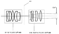
도 13a 및 도 13b는 제1 빔 익스팬더 블록(400) 및 이동가능한 빔 익스팬더 블록(500)의 2개의 세팅을 도시한다.
도 14는 Z 스캐너(450)의 중간 초점면을 도시한다.
도 15는 오브젝티브(700)의 실시를 도시한다.
도 16은 목표 영역에서 구부러진 초점면을 도시한다.
도 17은 XY 스캐너 경사각도의 노모그램을 도시한다.
도 18은 이동가능한 빔 익스팬더 위치의 노모그램을 도시한다.
도 19는 컴퓨터를 이용한 제어 방법의 단계들을 도시한다.Figure 1 shows a surgical laser delivery system (1).
Fig. 2 shows an excluded wavefront W and a Gaussian wavefront G. Fig.
Figures 3A and 3B illustrate light rays at the best scanned focal plane.
3C shows the definition of the focus radius.
Fig. 4 shows the relationship between the RMS wavefront error [omega] and the Strobe S ratio.
Figure 5 shows a reference point for ophthalmic surgery.
Figs. 6A and 6B conceptually show the operation of the
Figures 7A and 7B illustrate various uses of efficient Z scanning capabilities.
Figures 8A-8D illustrate the implementation of the
Figure 9 shows the implementation of a
Figure 10 shows a table of configurations comprising zero, one or two Z depth scanners and zero, one or two NA adjusters.
Figures 11A-11C illustrate an XY scanner with 2, 3, and 4 scanning mirrors.
Figures 12A-12D show the corresponding optical numerical apertures (NA opt (z)) as a function of the aberration and Z focal depth as a function of the numerical aperture.
Figs. 13A and 13B show two settings of the first beam expander block 400 and the movable beam expander block 500. Fig.
14 shows the mid-focal plane of the Z scanner 450. FIG.
FIG. 15 shows an implementation of an object 700.
Figure 16 shows a focal plane curved in the target area.
17 shows a nomogram of the XY scanner tilt angle.
Figure 18 shows the nomogram of the movable beam expander position.
Fig. 19 shows the steps of a control method using a computer.
본 발명의 몇몇 구체예들은 펨토초 레이저 펄스를 사용하여, 눈의 렌즈(lens)에서 수술을 위한 시스템을 포함한다. 또한 몇몇 일체화된 구체예들은 각막 및 렌즈 수술 절차 모두를 수행할 수 있다. 눈의 렌즈에서 안과 수술을 수행하는 것은 각막 절차보다 질적으로 상이한 요구조건에 관련된다.Some embodiments of the present invention include a system for surgery in a lens of the eye using femtosecond laser pulses. Also, some integrated embodiments can perform both corneal and lens surgical procedures. Performing ophthalmic surgery on the lens of the eye is related to qualitatively different requirements than corneal procedure.
현재의 설명된 렌즈 수술 레이저 시스템 및 각막 시스템 사이의 핵심적인 차이점은 다음을 포함한다:The key differences between the currently described lens surgical laser system and the corneal system include:
1. 펨토초 레이저 펄스가 확실하게 발생되는 것이다. 높은 반복률 펨토초 펄스는 시스템의 조작자를 위한 훨씬 더 높은 제어 및 정확성을 제공하면서, 훨씬 작은 펄스 당 에너지의 사용을 허용한다. 하지만, 확실하게 펨토초 펄스를 발생시키는 것은 몇몇의 현존하는 시스템에 의해 사용된, 나노초 또는 피코초 펄스보다 현저하게 더 큰 시도이다.1. The femtosecond laser pulse is surely generated. The high repetition rate femtosecond pulses allow much smaller energy per pulse to be used, while providing much higher control and accuracy for the operator of the system. However, certainly generating femtosecond pulses is a significantly larger attempt than nanosecond or picosecond pulses used by some existing systems.
2. 각막 및 수성 전방(anterior aqueous chamber)을 포함하여 바로 수술 목표, 렌즈에 도달하면서, 5밀리미터까지의 굴절 매체를 통해 전파될 때 수술 레이저 빔은 현저하게 굴절된다. 반면에, 각막 수술을 위해 사용되는 레이저 빔은 밀리미터의 일부의 깊이에 초점 맞춰지고, 이에 따라 수술 시스템으로부터 각막에 들어감에 따라 실질적으로 굴절되지 않는다.2. The surgical laser beam is significantly refracted when it is propagated through the refractive media up to 5 mm, reaching the surgical target, including the cornea and the anterior aqueous chamber. On the other hand, the laser beam used for corneal surgery is focused at a depth of a portion of the millimeter, and thus is not substantially refracted as it enters the cornea from the surgical system.
3. 수술 레이저 전달 시스템은 예를 들어, 5㎜의 일반적인 깊이에서의 전측/전방으로부터 10㎜의 일반적인 깊이에서의 후측/후방까지 전체 수술 영역을 스캔하도록 구성된다. 이런 5㎜ 이상 깊이-스캐닝 범위, 또는 "Z 스캐닝 범위"는 각막에 대한 수술을 위하여 사용된 1 ㎜ 깊이-스캐닝보다 현저하게 광범위하다. 일반적으로, 수술 광학, 실질적으로 여기서 사용된 높은 개구수 광학은, 특정한 작동 깊이에 레이저 빔을 초점 맞추는 데에 최적화된다. 각막 절차 동안에, 1㎜ 깊이-스캐닝은 최적화된 작동 깊이로부터 단지 적정한 벗어남을 야기한다. 반면에, 렌즈 수술 동안에 5 내지 10㎜의 스캔 동안에, 시스템은 고정된 최적화된 작동 깊이로부터 떨어져 구동된다. 따라서, 렌즈 수술 레이저 전달 시스템은 훨씬 개선된 적응제어 광학을 채택하여 렌즈 수술에 의해 요구된 광범위한 깊이-스캐닝 범위를 스캔할 수 있다.3. The surgical laser delivery system is configured to scan the entire surgical area from the front / front at a general depth of 5 mm to the rear / back at a general depth of 10 mm, for example. Such a depth-scanning range of 5 mm or more, or "Z scanning range" is significantly wider than 1 mm depth-scanning used for surgery on the cornea. In general, the surgical optics, substantially the high numerical aperture optics used herein, are optimized to focus the laser beam at a specific working depth. During the corneal procedure, 1 mm depth-scanning results in only a reasonable deviation from the optimal working depth. On the other hand, during a scan of 5 to 10 mm during lens surgery, the system is driven away from a fixed, optimized working depth. Thus, the lens surgery laser delivery system employs a much improved adaptive control optics to scan the wide depth-scanning range required by lens surgery.
4. 몇몇의 구체예들은 각막 및 렌즈 모두에서 수술을 수행하도록 구성된다는 의미에서 일체화된다. 이런 일체화된 구체예들에서 깊이-스캐닝 범위는 훨씬 어려운 시도를 취하면서, 5㎜ 대신에 10㎜까지일 수 있다. 4. Some embodiments are integrated in the sense that they are configured to perform surgery on both the cornea and the lens. In these integrated embodiments, the depth-scanning range can be up to 10 mm instead of 5 mm, taking even more difficult attempts.
5. 라식(LASIK)의 많은 변종과 같은, 각막 수술 절차 동안에, 레이저 빔은 ("XY 평면에서") 광학축에 대하여 수직으로 스캔된다. 일반적인 절차에서 XY 스캐닝 범위는 단지 10㎜의 직경을 갖는 각막의 중심부를 덮는다. 하지만, 일체화된 수술 시스템에서 추가 컷(cut)이 또한 형성될 수 있다. 컷의 일 형태는 종래의 수술 도구 및 흡인 니들(aspiration needle)을 위한 눈의 내부에 대한 접근을 제공하는, 엔트리 컷(entry cut)이다. 컷의 다른 형태는 각막윤부절개술(limbal relaxing incision; LRI)이고, 이는 혈관 아케이드(vascular arcade)에 대한 바로 전방 각막 윤부에서 한 쌍의 절개를 만드는 것을 포함한다. 이런 아치형 절개의 길이, 깊이 및 위치를 조절함으로써, 하나는 각막 난시에서 변화를 유도할 수 있다. 엔트리 컷 및 LRI은 일반적으로, 12㎜의 직경을 갖는, 각막의 주변에 위치될 수 있다. 10㎜ 내지 12㎜ 직경의 XY 스캐닝 직경을 증가시키는 것이 라식 플랩(flap)의 일정한 직경에 비해서 20% 증가인 것인 반면에, 축외(off-axis) 수차(aberration)가 초점면에서 필드 직경의 더 높은 힘에 비례하여 성장하기 때문에, 이러한 직경에서의 제어 하에 레이저 전달 시스템의 축외 수차를 간직하는 것이 중요한 시도이다.5. During corneal surgery procedures, such as many variants of LASIK, the laser beam is scanned perpendicular to the optical axis (in the "XY plane"). In the general procedure, the XY scanning range covers the center of the cornea with a diameter of only 10 mm. However, additional cuts may also be formed in an integrated surgical system. One form of cut is an entry cut that provides access to the interior of the eye for conventional surgical tools and aspiration needles. Another form of cut is the limbal relaxing incision (LRI), which involves making a pair of incisions in the anterior corneal limbus just for the vascular arcade. By adjusting the length, depth and position of these arcuate incisions, one can induce a change in corneal astigmatism. The entry cut and LRI can generally be located around the cornea, with a diameter of 12 mm. While increasing the XY scanning diameter of 10 mm to 12 mm diameter is a 20% increase relative to a constant diameter of the LASIK flap, off-axis aberration is a factor of field diameter It is an important attempt to keep the off-axis aberration of the laser delivery system under such diameter control, since it grows in proportion to higher forces.
6. 렌즈 레이저 수술 절차는 복잡한 이미징(imaging) 시스템으로부터 유도를 요구할 수 있다. 몇몇 이미징 장치에서 윤부 혈관(limbal blood vessel)은 확인되어 눈에 기준표시로서 작용하고, 눈의 수술전 진단 동안에 확인된 기준 좌표에 대한 몇몇 경우에, 수술 시간 동안에 눈의 시클로-회전 정렬(cyclo-rotational alignment)을 보정한다. 수술 영역의 주변에 선택된 혈관은 수술에 의해 가장 많이 흔들리지 않을 수 있고 이에 따라 가장 확실하다. 하지만, 이러한 주변 혈관에 배향된 이미징 시스템은 이미징 광학을 요구하여 10㎜보다 큰, 예를 들어, 12㎜ 반경을 갖는 영역을 촬영한다.6. Lens Laser surgical procedures may require induction from a complex imaging system. In some imaging devices, limbal blood vessels are identified and act as reference indicators in the eye, and in some cases for reference coordinates identified during pre-operative diagnosis of the eye, the cyclo- rotational alignment. Selected blood vessels around the surgical area may not be shaken most often by surgery and thus most certainly. However, imaging systems oriented to these peripheral blood vessels require imaging optics to photograph areas having a radius greater than 10 mm, for example, 12 mm.
7. 레이저 빔은 눈 내에 광학 경로를 따라 전달하는 동안에 다양한 수차를 성장시킨다. 레이저 전달 시스템은 이런 수차를 위하여 보상함으로써 정확성을 향상시킬 수 있다. 이런 수차의 추가적인 양상은 "색 수차(chromatic aberration)"로서 참조된 사실, 광의 주파수에 따른다는 것이다. 이런 주파수에 따르는 수차를 보상하는 것은 시스템에 대한 시도를 증가시킨다. 이런 색 수차를 보상하는 것의 어려움은 레이저 시스템의 레이저 빔의 대역폭에 따라 증가한다. 빔의 스펙트럼 대역폭이 펄스 길이에 대하여 반비례한다는 것이 상기된다. 따라서, 펨토초 펄스를 위한 대역폭은 종종 펨토초 레이저 시스템에서 훨씬 양호한 색 보상을 필요하게 만드는, 10배(an order of magnitude) 이상만큼 피코초 펄스의 대역폭보다 크다.7. The laser beam grows various aberrations while propagating along the optical path in the eye. The laser delivery system can improve accuracy by compensating for such aberrations. An additional aspect of this aberration is in fact referred to as "chromatic aberration ", depending on the frequency of the light. Compensating for these frequency dependent aberrations increases the effort on the system. The difficulty of compensating for this chromatic aberration increases with the bandwidth of the laser beam of the laser system. It is recalled that the spectral bandwidth of the beam is inversely proportional to the pulse length. Thus, the bandwidth for a femtosecond pulse is often greater than the bandwidth of a picosecond pulse by an order of magnitude or more, which often requires better color compensation in a femtosecond laser system.
8. 높은 반복률 펨토초 레이저 수술 시스템을 사용하는 수술 절차는 목표 조직에서 목표 위치에 대한 절대적으로 및 앞선 펄스에 대하여 상대적으로 각각의 펄스를 위치시키는 데에 높은 정확성을 요구한다. 예를 들어, 레이저 시스템은 펄스들 사이의 시간 내에 수 마이크론만큼만 빔을 재배향하도록 요구될 수 있고, 이는 약 마이크로초일 수 있다. 2개의 연속적인 펄스 사이의 시간이 짧고 펄스 위치에 대한 정확성 요구조건이 높기 때문에, 현존하는 낮은 반복률 렌즈 수술 시스템에 사용된 바와 같은 수동 타켓팅(targeting)은 더 이상 적절하거나 실현가능하지 않다.8. The surgical procedure using a high repetition rate femtosecond laser surgery system requires high accuracy in positioning the respective pulses relative to the absolute and preceding pulses for the target position in the target tissue. For example, the laser system may be required to redirect the beam only a few microns in time between pulses, which may be about microseconds. Manual targeting as used in existing low repetition rate lens surgery systems is no longer appropriate or feasible because the time between two consecutive pulses is short and the accuracy requirements for pulse positions are high.
9. 레이저 전달 시스템은 유지된 시간, 스펙트럼 및 공간 인티그리티(integrity)를 갖는, 굴절 매체를 통해 펨토초 레이저 펄스를 눈의 렌즈의 전체적인 수술 볼륨(volume)으로 전달하도록 구성된다. 9. The laser delivery system is configured to deliver femtosecond laser pulses through the refractive medium to the overall surgical volume of the eye's lens, having a maintained time, spectrum and spatial integrity.
10. 단지 수술 영역에서 조직이 수술 효과, 예를 들어 조직 절제(tissue ablation)를 야기하기에 충분하게 높은 에너지 밀도를 갖는 레이저 빔을 받아들이는 것을 보장하기 위하여, 레이저 전달 시스템은 대단히 높은 개구수(numerical aperture; NA)를 갖는다. 이런 높은 NA는 작은 스폿 크기(spot size)를 초래하고, 수술 절차를 위하여 필요한 제어 및 정확성을 제공한다. 개구수에 대한 일반적인 범위는 3 마이크론 이하의 스폿 크기를 초래하는, 0.3보다 큰 NA 값을 포함할 수 있다.10. In order to ensure that the tissue in the surgical area only receives a laser beam with a sufficiently high energy density to cause a surgical effect, for example tissue ablation, the laser delivery system has a very high numerical aperture numerical aperture NA). This high NA results in a small spot size and provides the necessary control and accuracy for the surgical procedure. A typical range for the numerical aperture may include NA values greater than 0.3, resulting in a spot size of 3 microns or less.
11. 렌즈 수술을 위한 레이저의 광학 경로의 복잡성이 부여된다면, 레이저 전달 시스템은 고성능 컴퓨터로 관리되는 이미징 시스템을 포함함으로써 높은 정확성 및 제어를 달성하는 반면에, 각막 수술 시스템은 이러한 이미징 시스템이 없거나 낮은 수준의 이미징으로 만족스러운 제어를 달성할 수 있다. 특히, 일반적으로 관습적인 관찰 빔뿐만 아니라, 시스템의 수술 및 이미징 기능은 모두 상이한 스펙트럼 대역에서 작동한다. 실시예로서, 수술 레이저는 1.0 내지 1.1 마이크론의 대역에서의 파장에서 작동할 수 있고, 관찰 빔은 0.4 내지 0.7 마이크론의 가시 대역에서 작동할 수 있으며, 이미징 빔은 0.8 내지 0.9 마이크론의 대역에서 작동할 수 있다. 일반적이거나 공유된, 광학 구성요소에서 빔 경로를 조합하는 것은 레이저 수술 시스템의 광학 상에 색 요구조건을 요구하는 것을 위치시킨다.11. Given the complexity of the optical path of the laser for lens surgery, the laser delivery system achieves high accuracy and control by including a high performance computer-managed imaging system, while the corneal surgical system has no or low imaging system Level imaging can achieve satisfactory control. In particular, the surgical and imaging functions of the system, as well as the conventional observation beam in general, all operate in different spectral bands. By way of example, the surgical laser may operate at a wavelength in the range of 1.0 to 1.1 microns, the observation beam may operate in the visible band of 0.4 to 0.7 microns, and the imaging beam may operate in the range of 0.8 to 0.9 microns . Combining the beam path in a common or shared, optical component places one requiring a color requirement on the optical surface of a laser surgical system.
차이점 1 내지 11은 (ⅱ) 펨토초 펄스를 갖는 (ⅰ)렌즈들 상의 안과 레이저 수술이 단지 나노초 또는 피코초 레이저 펄스를 사용하여, 각막 수술의 것 및 심지어 렌즈 수술과 질적으로 상이한 요구조건을 유도하는 몇몇 실시예들을 통해 도시한다.
도 1은 레이저 전달 시스템(1)을 도시한다. 상세하게 설명하기 이전에, 우리는 몇몇 구체예들이 이미징 또는 관찰 시스템을 갖는 도 1의 레이저 전달 시스템을 조합한다는 것을 언급한다. 라식 처리에서와 같은, 몇몇 각막 절차에서, 시표 추적기(eye tracker)는 일반적으로, 눈의 표면 상에, 이미징 및 이미지 처리 알고리즘에 의해 홍채의 중심의 확인과 같은 시각적 단서에 의해 눈의 위치 기준을 수립한다. 하지만, 수술 절차가 눈의 최외곽층, 각막에서 수행되기 때문에, 현존하는 시표 추적기는 깊이 정보 없는, 2차원 공간에서의 특성을 인지하고 분석한다. 종종, 각막은 고르게 납작하게 되어 표면을 정확히 2차원으로 만든다.Fig. 1 shows a
눈 안쪽에 깊은, 렌즈에서 레이저 빔을 초점 맞출 때 상황이 꽤 상이하다. 수정체는 이전의 측정과 수술 사이뿐 아니라 수술 동안에, 순응(accomodation) 동안에 위치, 형상, 두께 및 직경을 변하게 할 수 있다. 기계적인 수단에 의해 수술 장비에 눈을 부착시키는 것은 또한 불명확한 방식으로 눈의 형상을 변하게 할 수 있다. 이러한 부착 장치는 흡입링으로 눈을 고정시키거나(fixating), 평평하거나 구부러진 렌즈로 눈을 수차제거하는(aplanating) 것을 포함할 수 있다. 더욱이, 수술 동안에 환자의 이동은 추가적인 변화를 도입할 수 있다. 이런 변화는 눈 내에서 시각적 단서의 수 밀리미터의 변위만큼까지 추가될 수 있다. 따라서, 렌즈 또는 눈의 다른 내측부 상에 정밀 레이저 수술을 수행할 때, 윤부 또는 각막의 전방 표면과 같은 눈의 표면을 기계적으로 기준 표시하고 고정하는 것은 만족스럽지 않다.Deep inside the eye, the situation is quite different when focusing the laser beam on the lens. The lens can change position, shape, thickness and diameter during accomodation, as well as during surgery, as well as between previous measurements and surgery. Attaching the eye to the surgical equipment by mechanical means may also change the shape of the eye in an unclear manner. Such an attachment device may include fixing the eye with a suction ring and aplanating the eye with a flat or bent lens. Moreover, the movement of the patient during surgery can introduce additional changes. These changes can be added up to a displacement of a few millimeters of visual cues within the eye. Thus, when performing precision laser surgery on a lens or other medial side of the eye, it is unsatisfactory to mechanically mark and fix the surface of the eye, such as the limbus or the anterior surface of the cornea.
이런 문제점을 언급하기 위하여, 레이저 전달 장치(1)는 R.M. Kurtz, F. Raksi 및 M. Karavitis에 의한 동시에 계류 중인 미국 특허 출원 번호 12/205,844호에서 설명된 바와 같이, 이미징 시스템과 조합될 수 있고, 이는 이로써 전체에서 참고문헌에 의해 포함된다. 이미징 시스템은 수술 영역의 일부를 촬영하여 눈의 내측 특성을 기초로 하여 3차원 위치 기준을 수립하도록 구성된다. 이런 이미지는 수술 전에 생성될 수 있고 수술 절차와 평행하게 갱신될 수 있어 개별적인 변경 및 변화를 설명한다. 이미지는 높은 정확성 및 제어를 갖는 원하는 위치에 레이저 빔을 안전하게 배향하는 데에 사용될 수 있다.To address this problem, the
몇몇 실시에서, 이미징 시스템은 광 간섭 단층촬영(optical coherence tomography; OCT) 시스템일 수 있다. 이미징 시스템의 이미징 빔은 수술 빔과 부분적으로 또는 전부 공유된 광학 경로 또는 분리된 이미징 광학 경로를 가질 수 있다. 부분적으로 또는 전부 공유된 광학 경로를 갖는 이미징 시스템은 비용을 감소시키고 이미징 및 수술 시스템의 보정을 단순화시킨다. 이미징 시스템은 또한 레이저 전달 시스템(1)의 레이저와 동일하거나 상이한 광원을 사용할 수 있다. 이미징 시스템은 또한 자체적인 빔 스캐닝 서브시스템을 가질 수 있거나, 레이저 전달 시스템(1)의 스캐닝 서브시스템을 사용하게 할 수 있다. 이러한 OCT 시스템의 몇몇 상이한 구조는 참조된 동시 계류 중인 출원에서 설명된다.In some implementations, the imaging system may be an optical coherence tomography (OCT) system. The imaging beam of the imaging system may have an optical path partially or wholly shared with the surgical beam or a separate imaging optical path. An imaging system with a partially or fully shared optical path reduces cost and simplifies calibration of the imaging and surgical system. The imaging system may also use a light source that is the same as or different from the laser of the
레이저 전달 시스템(1)은 또한 가시 관찰 광학과 조합으로 실시될 수 있다. 관찰 광학은 수술 레이저의 조작자가 수술 레이저 빔의 효과를 관찰하고 관찰에 대한 빔을 제어하는 것을 돕는다.The
결국, 적외선 및 이에 따른 비가시 수술 레이저 빔을 사용하는, 몇몇 실시에서, 가시 주파수에서 작동하는 추가적인 추적 레이저가 채택될 수 있다. 가시 추적 레이저는 실시되어 적외선 수술 레이저의 경로를 추적하도록 실시될 수 있다. 추적 레이저는 목표 조직의 어떤 붕괴를 야기하지 않기에 충분히 낮은 에너지에서 작동될 수 있다. 관찰 광학은 목표 조직으로부터, 레이저 전달 시스템(1)의 조작자에게 반사된, 추적 레이저를 배향하도록 구성될 수 있다.Ultimately, in some implementations, using infrared and accordingly incompatible surgical laser beams, additional tracking lasers operating at visible frequencies may be employed. A visible tracking laser may be implemented to track the path of the infrared surgical laser. The tracking laser can be operated at a sufficiently low energy to not cause any collapse of the target tissue. The observation optics can be configured to direct a tracking laser, reflected from the target tissue, to the operator of the
도 1에서, 가시 관찰 광학 및 이미징 시스템에 연관된 빔은 예를 들어, 빔 스플리터(beam splitter)/색선별 거울(dichroic mirror)(600)을 통해 레이저 전달 시스템(1)으로 결합될 수 있다. 본 출원은 이미징, 관찰 및 추적 시스템을 갖는 레이저 전달 시스템의 다양한 조합을 광범위하게 언급하지 않을 것이다. 포함된 미국 특허 출원 12/205,844호에서 광범위하게 언급된, 이러한 조합의 많은 수는 본 출원의 전체 범위 내에서 모두 존재한다.In FIG. 1, the beam associated with the viewing optics and imaging system may be coupled to the
도 1은 레이저 전달 시스템(1)을 포함하고, 이는 레이저 엔진(100), 프리컴펜세이터(200; precompensator), XY 스캐너(300), 제1 빔 익스팬더 블록(400; beam expander block), 이동가능한 빔 익스팬더 블록(500), 빔 스플리터/색선별 거울(600), 오브젝티브(objective; 700) 및 환자 인터페이스(800; patient interface)를 포함하되, 제1 빔 익스팬더 블록(400) 및 이동가능한 빔 익스팬더 블록(500)은 연결하여 Z 스캐너(450)로 불릴 것이다.Figure 1 illustrates a
아래의 많은 실시에서 Z방향이 실질적으로 광학 요소의 광학축 또는 레이저 빔의 광학 경로를 따르는 방향인 종래 기술이 사용된다. Z 방향에 대하여 가로지르는 방향은 XY 방향이라 불린다. 넓은 의미에서 용어 가로지르는 방향은 몇몇 실시에서 가로지르는 방향 및 Z 방향은 상호 간에 엄격하게 수직일 수 없는 것을 포함하도록 사용된다. 몇몇 실시에서 가로지르는 방향은 방사방향 좌표에 대하여 더 양호하게 설명될 수 있다. 따라서, 용어 가르지르는 방향, XY 방향 또는 방사방향은 모두 대략 (그러나 어쩔수 없이 정확하게) Z 방향에 대하여 수직하는, 설명된 실시에서 유사한 방향을 나타낸다.
In many implementations below, the prior art is used wherein the Z-direction is substantially the direction along the optical axis of the optical element or the optical path of the laser beam. The direction crossing with the Z direction is called the XY direction. In a broad sense, the term traversing direction is used to include that in some implementations the traversing direction and the Z direction can not be strictly perpendicular to each other. In some implementations the direction of traversal may be better described with respect to radial coordinates. Thus, the term grasping direction, XY direction, or radial direction all indicate a similar direction in the described implementation, which is perpendicular to the Z direction, generally (but unequivocally precisely).
1. 레이저 엔진(100)1. Laser engine 100,
레이저 엔진(100)은 레이저를 포함하여 선결정된 레이저 파라미터(parameter)를 갖는 레이저 펄스를 방출할 수 있다. 이런 레이저 파라미터는 1 펨토초 내지 100 피코초 범위에, 또는 10 펨토초 내지 10 피코초 범위 내에 또는 몇몇 구체예에서 100 펨토초 내지 1 피코초 범위의 펄스 기간(duration)을 포함할 수 있다. 레이저 펄스는 0.1 마이크로줄 내지 1000 마이크로줄 범위, 다른 구체예에서 1 마이크로줄 내지 100 마이크로줄 범위의 펄스 당 에너지를 가질 수 있다. 펄스는 10 ㎑ 내지 100 ㎒ 범위, 다른 구체예에서 100 ㎑ 내지 1㎒ 범위의 반복 주파수를 가질 수 있다. 다른 구체예들은 이런 범위 제한의 조합, 예를 들어, 1 내지 1000 펨토초의 펄스 기간의 범위 내에서 떨어지는 레이저 파라미터를 가질 수 있다. 특정한 절차를 위한 레이저 파라미터는 예를 들어, 수술 전 절차 동안에 이런 넓은 범위 내에 선택될 수 있거나, 환자의 특정한 데이터 예를 들어, 그/그녀의 연령을 기초로 한 계산을 기초할 수 있다.The laser engine 100 may emit a laser pulse including a laser and having a predetermined laser parameter. Such laser parameters may include a pulse duration in the range of one femtosecond to 100 picoseconds, or in the range of 10 femtoseconds to 10 picoseconds, or in some embodiments in the range of 100 femtoseconds to 1 picoseconds. The laser pulses may have an energy per pulse in the range of from 0.1 micron to 1000 microns, and in other embodiments from 1 micron to 100 microns. The pulse may have a repetition frequency in the range of 10 kHz to 100 MHz, in other embodiments in the range of 100 kHz to 1 MHz. Other embodiments may have laser parameters falling within a range of combinations of these range limits, for example, within a pulse duration of 1 to 1000 femtoseconds. The laser parameters for a particular procedure may be selected within this broad range, for example, during pre-operative procedures, or may be based on patient-specific data, for example, calculations based on his / her age.
레이저 엔진(100)의 실시예는 Nd:glass 및 Nd:Yag 레이저, 및 다양한 다른 레이저를 포함할 수 있다. 레이저 엔진의 작동 파장은 적외선 또는 가시광선 범위에서 존재할 수 있다. 이런 구체예들에서 작동 파장은 700㎚ 내지 2 마이크론 범위에서 존재할 수 있다. 몇몇 경우에 작동 파장은 예를 들어, Yb 또는 Nd를 기초로 한 적외선 레이저에서, 1.0 내지 1.1 마이크론 범위에서 존재할 수 있다.Embodiments of laser engine 100 may include Nd: glass and Nd: Yag lasers, and various other lasers. The operating wavelength of the laser engine may be in the infrared or visible range. In these embodiments, the operating wavelength may be in the range of 700 nm to 2 microns. In some cases, the operating wavelength may be in the range of 1.0 to 1.1 microns, for example, in an infrared laser based on Yb or Nd.
몇몇 실시에서 레이저 펄스의 레이저 파라미터는 조절가능하고 변경가능할 수 있다. 레이저 파라미터는 짧은 스위치 타임(switch time)으로 조절가능할 수 있고 이에 따라 수술 레이저 전달 시스템(1)의 조작자가 복합 수술 동안에 레이저 파라미터를 변하게 할 수 있다. 파라미터의 이러한 변화는 레이저 전달 시스템(1)의 센싱(sesing) 또는 이미징 서브시스템에 의한 판독에 대하여 개시될 수 있다. In some implementations, the laser parameters of the laser pulses may be adjustable and changeable. The laser parameters may be adjustable with a short switch time so that the operator of the surgical
다른 파라미터 변화는 레이저 전달 시스템이 제1 수술 절차, 이어지는 제2의, 상이한 수술 절차에 먼저 사용될 수 있는 동안에 다중 단계 절차의 일부로서 수행될 수 있다. 실시예는 우선 눈의 렌즈의 영역에서 하나 이상의 수술 단계, 예를 들어 수정체낭절개 단계, 이어지는 눈의 각막 영역에서 제2 수술 절차를 수행하는 것을 포함한다. 이런 절차는 다양한 순서로 수행될 수 있다.Other parameter changes can be performed as part of a multiple step procedure while the laser delivery system can be used first in a first surgical procedure, followed by a second, different surgical procedure. Embodiments include first performing at least one surgical procedure in the area of the lens of the eye, such as a capsular incision, followed by a second surgical procedure at the corneal area of the eye. These procedures can be performed in various orders.
상대적으로 낮은 펄스 당 에너지를 갖는 초당 수만 내지 수십만 샷(shot)의 펄스 반복률에서 작동하는 높은 반복률 펄스의 레이저는 수술 적용에 사용될 수 있어 특정한 장점을 달성한다. 이러한 레이저는 상대적으로 낮은 펄스 당 에너지를 사용하여 레이저 유도된 광파괴에 의해 야기된 조직 효과를 국부화한다. 몇몇 실시에서, 예를 들어, 파괴된 조직의 한도는 수 마이크론 또는 수십 마이크론으로 제한될 수 있다. 이런 국부화된 조직 효과는 레이저 수술의 정확성을 향상시킬 수 있고, 특정한 수술 절차에서 바람직할 수 있다. 이러한 수술의 다양한 실시에서, 수백, 수천 또는 수백만 펄스가 인접하고, 거의 인접하거나, 제어된 거리만큼 분리된 스폿(spot)의 순서로 전달될 수 있다. 이런 실시는 특정한 원하는 수술 효과, 예를 들어, 조직 절개, 분리 또는 파편화를 달성할 수 있다.A laser with a high repetition rate pulse, which operates at a pulse repetition rate of tens to hundreds of thousands of shots per second with relatively low energy per pulse, can be used in surgical applications to achieve certain advantages. These lasers use relatively low per pulse energy to localize the tissue effect caused by the laser induced light breakdown. In some implementations, for example, the extent of the destroyed tissue may be limited to a few microns or tens of microns. This localized tissue effect may improve the accuracy of laser surgery and may be desirable in certain surgical procedures. In various implementations of these surgeries, hundreds, thousands or millions of pulses may be delivered in the order of adjacent, near, or separated by a controlled distance. Such an implementation may achieve certain desired surgical effects, such as tissue incision, dissection or fragmentation.
스캔 패턴 및 펄스의 파라미터는 다양한 방법에 의해 선택될 수 있다. 예를 들어, 이들은 렌즈의 광학적 또는 구조적 성질의 수술 전 척도를 기초로 할 수 있다. 레이저 에너지 및 스폿 분리는 또한 연령에 따른 알고리즘 도는 렌즈의 광학적 또는 구조적 성질의 수술 전 척도를 기초로 선택될 수 있다.
The scan pattern and the parameters of the pulse can be selected by various methods. For example, they may be based on pre-operative measures of optical or structural properties of the lens. Laser energy and spot separation can also be selected based on age-based algorithms or pre-op scales of optical or structural properties of the lens.
2. 2. 프리컴펜세이터Precompensator (200)(200)
도 2는 레이저 빔의 파면이 몇몇 상이한 원인에 대하여 몇몇 상이한 방법으로 이상적인 거동으로부터 벗어날 수 있다는 것을 도시한다. 큰 그룹의 이런 편차는 수차(aberration)라고 불린다. 수차 (및 다른 파면 왜곡)은 이상적인 축주위 가우스 이미지점(image point)들로부터 실제 이미지점을 대신한다. 도 2는 출사 동공(ExP)을 통해 빠져나가는 광의 파면을 도시한다. 왜곡된 구면 파면(G)은 동공으로부터 나오고 파면(G)의 곡률의 중심에서 점(P1)으로 수렴된다. G는 또한 가우스 기준 구체(reference sphere)라고 불린다. 벗어난 파면(W)은 G로부터 벗어나고 상이한 점(P2)으로 수렴된다. 점(Q1)에서 벗어난 파면(W)의 수차(ΔW)는 왜곡된 기준구체(G)에 대한 경로의 광학 길이에 의해 특징지어질 수 있고: ![]()
![]()
![]()
![]()
일반적으로, 수차(ΔW)는 초점면에서 뿐만 아니라, 출사 동공에서 모두 좌표에 따른다. 따라서, 이런 수차(ΔW)는 또한 상호관계함수로서 사료될 수 있다: r'만큼 광학축 상에서 P1으로부터 제거되고, 이미지가 P2로 수렴되는 점들의 세트는 표면(W) 상에 위치되고, 이는 출사 동공(ExP)에서 방사방향 거리(r)로 ΔW의 양만큼 기준 구체(G)로부터 벗어난다는 것이 나타난다. 회전 대칭 시스템을 위하여, Generally, the aberration? W depends on the coordinates not only in the focal plane but also in the exit pupil. Therefore, this aberration? W can also be regarded as a correlation function: a set of points, removed from P1 on the optical axis by r ', from which the image converges to P2, is located on the surface W, It appears that the pupil ExP deviates from the reference sphere G by the amount of DELTA W at the radial distance r. For a rotationally symmetric system,

여기서 r'은 초점면에서 이미지점(P2)의 방사방향 좌표이고 r은 동공에서 점(Q1)의 방사방향 좌표이다. 각도 의존성이 구면각, Θ에 의해 표시된다. n = 2p + m은 양의 정수이고, 2l + m a nm은 벗어난 파면(W)의 팽창 계수이다. 참고로, 예를 들어 SPIE Optical Engineering Press의 Virendra N. Mahajan에 의한 Optical Imaging and Aberrations, Part Ⅰ. Geometrical Optics를 참고한다. 수차 용어 중 차수(i)는 i = 2l + m + n에 의해 주어된다.Where r 'is the radial coordinate of the image point P2 on the focal plane and r is the radial coordinate of the point Q1 on the pupil. Angular dependence is indicated by the spherical angle, [theta]. n = 2p + m is a positive integer, and 2l + m a nm is the expansion coefficient of the wave front (W) deviated. For reference, for example, Optical Imaging and Aberrations by Virendra N. Mahajan of SPIE Optical Engineering Press, Part I. See Geometrical Optics. The order (i) of the aberration terms is given by i = 2l + m + n.
i = 4까지 용어들이 주된 수차에 연관된다: 구형, 코마(coma), 난시, 시야 곡률 및 왜곡. 2l + m a nm 수차 계수 및 이런 주된 수차들 사이의 실제 연관성은 문헌으로 기록된다. 점 물체를 촬영하는 시스템을 위한, 이미지 반경(r')에 대한 수차의 명확한 의존성은 무차원 변수 ρ = r/a를 도입함으로써 억제될 수 있고, 여기서 a는 출사 동공의 가로지르는 선형 한도, 예를 들어 이의 반경이다:Terms up to i = 4 are associated with the main aberrations: spherical, coma, astigmatism, field of view curvature and distortion. The 2l + m a nm aberration coefficients and the actual relevance between these major aberrations are documented in the literature. For a system for imaging point objects, a clear dependence of the aberration on the image radius r 'can be suppressed by introducing a dimensionless parameter p = r / a, where a is the transverse linear extent of the exit pupil, For example:

여기서,here,

이런 표기법의 이익은 수차 계수(a nm)들 모두가 길이의 치수를 갖고, 출사 동공에서 상응하는 수차의 최대값을 나타낸다. 이런 표기법에서, 예를 들어, 구면 수차(spherical aberration)가 수차 계수(a40)에 의해 특징지어진다. The advantage of this notation is that all of the aberration coefficients (a nm ) have a length dimension and represent the maximum value of the corresponding aberration in the exit pupil. In this notation, for example, the spherical aberration is characterized by the aberration coefficient (a 40 ).
수차 계수(a nm)에 대한 수차의 설명이 수학적으로 잘 정의되는 반면에, 이는 항상 실험적으로 가장 접근가능한 접근법은 아니다. 따라서, 3개의 대안적인 수차 척도가 다음에 설명된다.While the description of aberrations for aberration coefficients (a nm ) is well defined mathematically, this is not always the experimentally most accessible approach. Thus, three alternative aberration measures are described below.
동일한 정맥의 실험 접근성 및 시험가능성에서, 생물학적 조직 예를 들어, 눈에서 빔의 거동은 측정하기 위하여 가장 쉽지 않을 수 있다는 것이 지시된다. 도움이 되도록, 연구는 눈에서 광선이 물리적으로 적절한 염분 농도를 갖는 염수에서 광선에 대하여 꽤 유사하게 거동할 수 있고, 질적으로 측정되고 설명될 수 있다는 나타난다. 따라서, 눈에서 레이저 전달 시스템의 거동이 설명될 때 적용에 걸쳐, 이런 설명은 설명된 눈 조직 또는 상응하는 염수 중 어느 하나에서 거동을 언급하는 것이 이해된다.In the same vein experimental accessibility and testability, it is indicated that the behavior of the beam in the biological tissue, for example in the eye, may not be the easiest to measure. To the best of our knowledge, research has shown that light rays in the eye can behave quite similarly to rays in saline water with physically appropriate salinity, and can be measured and described qualitatively. Thus, throughout the application when the behavior of the laser delivery system in the eye is described, it is understood that this description refers to the behavior in any of the described eye tissues or the corresponding saline.
도 3a 내지 도 3c는 수차의 제2 척도를 도시한다. 깊이(A)에서의 초점면(210)에서 빔을 초점 맞추도록 구성되었던, 레이저 전달 시스템(1)은 대신에 깊이(B)에서의 작동 초점면(211)에서 빔을 초점 맞추도록 작동된다면 구면 수차를 야기할 수 있다. 레이저 빔의 초점이 초점면(210)으로부터 초점면(211)으로 이동될 때, 이러한 상황이 예를 들어, 3차원 스캐닝 절차 동안에 발생할 수 있다.Figures 3A-3C show a second measure of the aberration. The
도 3a는 레이저 전달 시스템(1)이 최적 초점면(210)에 광선을 초점 맞출 때의 경우를 도시한다. 광선은 꽤 좁은 방사방향 한도, 또는 반경(rf(A))의 최적 초점면(210)에서 스폿("초점")을 통과한다. 이런 방사방향 한도(rf(A))는 다양한 원인, 예를 들어, 광 빔의 회절에 대한 영보다 클 수 있다. 초점의 반경은 1개 이상의 방법으로 정의될 수 있다. rf(A)의 일반적인 정의는 스크린의 위치가 축 또는 Z 방향을 따라 변하게 됨에 따라 스크린 상의 광 스폿의 최소 반경이다. 이런 Z 깊이는 종종 "최소 착각점(point of least confusion)"이라 불린다. 이런 정의는 도 3c에 관련하여 더 개선된다.Figure 3A shows the case when the
도 3b는 레이저 전달 시스템(1)이 최적 초점면(210)을 벗어나 작동 초점면(211)으로 약간의 거리 예를 들어, 수 밀리미터만큼 초점을 스캔할 때의 경우를 도시한다. 가시적으로, 광선은 구면 수차를 야기하는, rf(A) 보다 큰 반경(rf(B))의 초점을 통과한다. 다양한 정확도의 수학식은 수차 계수(anm) 및 초점 반경(rf)을 연결하면서 성장되어 왔다. 몇몇 경우에, 초점 반경(rf)은 amn 수차 계수보다 수차를 수량화하는 데에 실험적으로 더 접근가능한 척도이다.3B shows a case where the
도 3c는 초점 반경(rf)의 더 나은 양적 정의를 도시한다. 도 3c는 빔의 중심으로부터 측정된, 반경(r)의 스폿에 포함된 에너지를 도시한다. 초점 반경(rf)의 광범위하게 받아들여진 정의는 빔의 에너지의 50%가 내부에 포함된, 반경이다. "A"로 표기된 곡선은 회절 제한된 빔에서, 도 3a에서와 같이, 빔이 최적 초점면(210)에 초점 맞추어질 때, 빔의 에너지의 50%는 rf(A)의 유용한 정의를 제공하면서, 반경 r = 0.8 마이크론의 스폿에서, 포함되거나 둘러싸일 수 있다.Figure 3c shows a better quantitative definition of the focal radius r f . Figure 3c shows the energy contained in a spot of radius r, measured from the center of the beam. The widely accepted definition of the focal radius (r f ) is the radius within which 50% of the beam's energy is contained. The curve labeled "A" is the diffraction limited beam, when the beam is focused on the best focal plane 210, as in Figure 3a, 50% of the energy of the beam provides a useful definition of r f (A) , At a radius r = 0.8 microns.
레이저 빔의 에너지가 제대로 또는 분명하게 정의된 초점에 놓여진다면, 레이저 유도 광학 브레이트다운(laser induced optical breakdown; LIOB)을 기초로 한 수술 절차는 더 높은 정확성 및 효율성, 및 더 작은 원치않는 효과를 가질 수 있다. LIOB는 강도(플라즈마-) 쓰레시홀드(threshold)를 갖는 상당한 비선형 공정이다: 일반적으로 플라즈마 쓰레시홀드보다 높은 강도를 갖는 빔에 노출된 조직은 플라즈마가 되는 반면에, 플라즈마 쓰레시홀드 아래의 강도를 갖는 빔에 노출된 조직은 플라즈마 전이를 겪지 않는다. 따라서, 수차에 의한 초점의 폭 넓히기는 플라즈마 쓰레시홀드보다 높은 초점에서의 강도를 달성하는 빔의 일부를 감소시키고 강도가 쓰레시홀드 아래로 유지되는 빔의 일부를 증가시킨다. 후자의 이런 빔의 일부는 목표 조직에 의해 효율적으로 흡수되지 않고 눈 조직을 통해, 잠재적으로 원치않는 각막 노출을 야기하는, 대부분의 경우에 망막으로 전파된다. If the energy of the laser beam is placed in a well-defined or clearly defined focus, the surgical procedure based on laser induced optical breakdown (LIOB) will have higher accuracy and efficiency, and less unwanted effect . LIOB is a significant nonlinear process with a strength (plasma) threshold: Generally, the tissue exposed to a beam having a higher intensity than the plasma threshold is plasma, while the intensity below the plasma threshold Lt; / RTI > does not undergo plasma transitions. Thus, widening the focus by aberration reduces a portion of the beam that achieves intensity at a higher focus than the plasma etch and increases the portion of the beam whose intensity is kept below the threshold. The latter part of this beam is propagated to the retina in most cases, which is not efficiently absorbed by the target tissue, but through the eye tissue, resulting in potentially unwanted corneal exposure.
각막을 보정하는 것을 목표로 하는 수술 절차를 위하여, 각막의 두께가 실질적으로 0.6㎜이고, 거의 드문 경우에 더 두꺼우나 여전히 1㎜를 넘지 않기 때문에, 초점면은 일반적으로 최적 또는 공칭 깊이로부터 약 0.6㎜만큼만 (광학축을 따르는) Z방향으로 스캔되거나 이동된다. "B"로 표기된 곡선은 빔의 초점면이 최적 초점면(210)으로부터 약 1㎜(각막 절차를 위한 상한 추정치)만큼 작동 초점면(211)으로 이동될 때, 빔의 에너지의 50%는 rf(B)= 1.8마이크론의 초점 반경 내에 포함된다는 것을 도시한다. 이런 이동이 수차를 도입하는 반면에, 척도가 제한된다. 따라서, 몇몇 현존하는 각막 레이저 시스템은 전혀 이런 수차를 보상하지 않는 반면에, 다른 것들은 약간 제한된 수준의 보상만을 도입한다. For a surgical procedure aimed at correcting the cornea, the focal plane is generally about 0.6 mm from the optimal or nominal depth, because the thickness of the cornea is substantially 0.6 mm, and in rare cases it is thicker, Mm in the Z direction (along the optical axis). The curve labeled "B" indicates that when the focal plane of the beam is moved from the best focus plane 210 to the working focal plane 211 by about 1 mm (upper limit estimate for the cornea procedure), 50% f (B) = 1.8 microns. < / RTI > While this shift introduces aberrations, the scale is limited. Thus, some existing corneal laser systems do not compensate for such aberrations at all, while others introduce only a somewhat limited amount of compensation.
수차 계수(amn) 및 초점 반경(rf) 이외에, 수차의 제3 척도는 소위 스트렐비(strehl ratio; S)이다. 시스템의 스트렐비(S)는 동일하고 완벽한 이미징 시스템의 이론적인 최대 피크 강도에 의해 나누어진 시스템의 초점면에서 빔의 피크 강도로서, 점원으로부터 빠져나가는 빔을 참조하여 정의될 수 있고, 이는 회절 제한에서 작용한다. 동등한 정의는 또한 문헌에서 공지되고, 스트렐비(S)의 정의의 범위 내에 존재한다.In addition to the aberration coefficient (a mn ) and the focus radius (r f ), the third measure of the aberration is the so-called strehl ratio (S). The Struelvy (S) of the system can be defined with reference to the beam exiting the point source as the peak intensity of the beam in the focal plane of the system divided by the theoretical maximum peak intensity of the same and complete imaging system, Lt; / RTI > Equivalent definitions are also known in the literature and are within the definition of Streby (S).
이런 정의에 상응하는, S의 값이 작을수록, 수차는 커진다. 벗어나지 않는 빔은 S = 1을 갖고, 종래에는 S > 0.8일 때, 이미징 시스템은 회절 제한되는 것으로 알려진다.The smaller the value of S, which corresponds to this definition, the larger the aberration. The unabsorbed beam has S = 1, and conventionally when S> 0.8, the imaging system is known to be diffraction limited.
수차의 제4 정의는 출사 동공(ExP)에서 전체 파면에 걸쳐 평균을 낸, 도 2의 왜곡되지 않는 파면(G)으로부터 벗어난 파면(W)의 편차(ΔW)를 표시하는 ω, 평균평방근(root-mean-square) 또는 RMS, 파면 오차이다. ω는 무차원 양을 만드는, 빔의 파장의 단위로 표시된다. The fourth definition of the aberration is ω which represents the deviation ΔW of the wavefront W deviated from the undistorted wavefront G of FIG. 2, averaged over the entire wavefront from the exit pupil ExP, -mean-square) or RMS, wavefront error. ω is expressed in units of the wavelength of the beam, making a dimensionless amount.
도 4는 상대적으로 작은 수차에 대하여 ω 및 S는 다음의 실험식에 의해 관련된다는 것을 도시한다:Figure 4 shows that for relatively small aberrations, [omega] and S are related by the following empirical formula:
수차의 형태에 상관없이,Regardless of the form of the aberration,
![]()
![]()
여기서 e는 자연로그의 밑(base)이다. Where e is the base of the natural logarithm.
상기의 수차의 척도들의 4개 모두는 문제점을 진단하고 레이저 전달 시스템(1)의 설계를 최적화하는 데에 유용하다. 따라서, 아래의 일반적인 용어 "수차 척도(aberration measure)"는 이런 척도들 또는 이들의 등가물 중 어떤 하나를 나타낼 수 있다. 특히, 수차를 증가시키는 것은 수차 계수(amn), 초점 반경(rf) 및 RMS 파면 오차(ω)의 증가에 의해 획득되나, 스트렐비(S)의 감소에 의해 획득된다.All four of the above aberration measures are useful for diagnosing problems and optimizing the design of the
이런 수차 척도들 사이의 관계는 특정한 실시예에서 구면 수차 계수(a40) 및상응하는 스트렐비(S)를 도시함으로써 설명된다. 실시예에서, 수술 레이저 시스템은 표면 아래의 상이한 깊이에서 눈 조직에 레이저 빔을 초점 맞춘다. 레이저 빔은 1 마이크로미터 파장 및 NA=0.3 개구수로, 회절 제한되고, 입사의 표준각도로 조직의 표면에 초점 맞춰진다. 이런 실시예의 개수는 시스템의 초점면 근처에서 스캔된 깊이와 동일한 두께의 평면 평행 플레이트(plate)를 추가하고, 염수를 위한 계산을 수행하는 효과와 유사할 수 있다.The relationship between these aberration measures is illustrated by showing the spherical aberration coefficient (a 40 ) and the corresponding Strobe ratio S in a specific embodiment. In an embodiment, the surgical laser system focuses the laser beam on the eye tissue at different depths below the surface. The laser beam is diffracted at a 1 micrometer wavelength and NA = 0.3 numerical aperture and focused on the surface of the tissue at a standard angle of incidence. The number of such embodiments may be similar to the effect of adding a plane parallel plate of the same thickness as the scanned depth near the focal plane of the system and performing calculations for saline.
조직의 표면은 수학식 (2) 및 (3)에 의해 특징지어진, 빔에 수차를 도입한다. 수차 계수(a40)에 의해 특징지어진, 구면 수차는 표면에서 영이고, 상당한 구조에 의한 스트렐비는 S=1이다.The surface of the tissue introduces aberration into the beam, which is characterized by equations (2) and (3). The spherical aberration, which is characterized by the aberration coefficient (a 40 ), is zero at the surface, and the Struel ratio by a considerable structure is S = 1.
라식 수술은 일반적으로 0.1㎜의 깊이로 플랩을 형성한다. 이런 깊이에서, 스트렐비(S)는 약 0.996으로 감소되고, 단지 작은 감소이다. 0.6㎜ 깊이에서 조차, 대략 각막의 후방 표면에서, S는 약 0.85이다. 이는 피크 강도의 무시할 수 없는 감소인 반면에, 여전히 레이저 빔 강도를 조정함으로써 보상될 수 있다.LASIK surgery usually forms a flap with a depth of 0.1 mm. At this depth, Strelevis S is reduced to about 0.996, only a small decrease. Even at a depth of 0.6 mm, at approximately the posterior surface of the cornea, S is approximately 0.85. This can be compensated by adjusting the laser beam intensity while still being a non-negligible decrease in peak intensity.
한편, 눈에서 수정체의 전방 표면을 특징짓는, 5㎜의 깊이에서, 스트렐비는 S = 0.054로 감소될 수 있다. 이런 깊이 및 스트렐비에서, 빔 강도는 플라즈마 쓰레시홀드 아래로 현저하게 감소되고, 이에 따라 빔은 LIOB를 발생시킬 수 없다. 피크 강도의 이런 급격한 손실은 원치않는 효과 예를 들어 망막의 노출 과다 또는 과도하게 증가된 버블 크기없이 레이저 파워를 증가시킴으로써 보상될 수 없다.On the other hand, at a depth of 5 mm, which characterizes the anterior surface of the lens in the eye, the Strule ratio can be reduced to S = 0.054. At such depths and strains, the beam intensity is significantly reduced below the plasma threshold, so that the beam can not generate LIOB. This abrupt loss of peak intensity can not be compensated for by undesirable effects, for example by increasing the laser power without excessive exposure of the retina or excessively increased bubble size.
표 1은 바로 설명된 스트렐비에 상응하는, 구면 수차(a40)를 도시한다. 가시적으로, 구면 수차는 조직-깊이에 따라 대략 선형으로 증가하는 반면에, 스트렐비(S)는 비선형 방식으로 거동한다:Table 1 shows the spherical aberration a 40 , which corresponds to the stress ratio just described. Visually, spherical aberration increases approximately linearly with tissue-depth, while Strelevis S behaves in a non-linear manner:
[표 1][Table 1]

수정체 상에 렌즈 용균(lysis), 수정체낭절개 또는 다른 수술 절차를 수행하는 것을 목표로 한 수술 절차에서, 초점면은 종종 렌즈의 전체 깊이에 걸쳐 스캔되고, 이는 5㎜만큼일 수 있다. 더욱이, 일체화된 각막-렌즈 시스템에서, 총 스캐닝 깊이는 각막으로부터 렌즈의 후방 표면까지, 약 10㎜ 연장될 수 있다. 도 3c에서 "C"로 표기된 곡선은 이런 경우 초점 반경이 rf(C) = 18마이크론까지 성장하고, 이 값은 너무 커서 rf(A) 및 rf(B)와 동일한 구성 상에 고르게 나타나지 않는다는 것이 나타낸다. 몇몇 구체예에서, 최적 초점면은 선택되어 깊이-스캐닝 범위에서 중간쯤 놓일 수 있고, 레이저 빔은 플러스/마이너스 5㎜ 깊이 범위로 스캔될 수 있다. 이런 경우에 rf(C)는 10마이크론으로 감소될 수 있다.In surgical procedures aimed at performing lens lysis, lens capsule incision or other surgical procedures on the lens, the focal plane is often scanned over the entire depth of the lens, which can be as much as 5 mm. Moreover, in an integrated cornea-lens system, the total scanning depth can be extended by about 10 mm from the cornea to the back surface of the lens. The curve labeled "C" in Fig. 3C then grows to a focal radius r f (C) = 18 microns, which is too large to appear evenly on the same configuration as r f (A) and r f . In some embodiments, the best focal plane can be selected and centered in the depth-scanning range, and the laser beam can be scanned in the plus / minus 5 mm depth range. In this case r f (C) can be reduced to 10 microns.
이런 큰 rf(C) 값은 다른 3개의 수차 척도들(a40, S, ω)에서 큰 양의 수차로 바뀌게 된다. 명확하게, 수십 밀리미터만을 스캔하는 각막 절차에 대하여, 렌즈 수술의 이런 큰 수차는 레이저 전달 시스템(1)의 설계를 위한 많은 시도를 취하여 원치않는 결과를 보상하거나 관리한다.This large r f (C) value is converted to a large amount of aberration in the other three aberration measures (a 40 , S, ω). Clearly, for corneal procedures that scan only a few tens of millimeters, this large aberration of lens surgery takes many attempts to design the
렌즈 수술에 연관된, 큰 수차 척도의 문제점을 언급하기 위하여, 몇몇 구체예들은 프리컴펜세이터(200)를 포함하여 구면 수차를 선보상하고(precompensate) 수차 척도를 향상시킨다. 이런 수차는 목표 조직에서, 또는 레이저 전달 시스템(1) 내의 광학 경로의 일부를 따르거나, 전체 광학 경로를 따라 성장될 수 있다.To address the problem of large aberration measures associated with lens surgery, some embodiments include
도 5는 수차 척도가 값을 추정한다는 것이 설명될 때 이어지는 경우에, 수차 척도(rf(C), a40, S, ω)가 광학축으로부터 방사방향 거리(r) 및 초점의 깊이(z)에 따르기 때문에, 이는 몇몇의 선택된 기준점(reference point)들에서 설명된 값을 추정하는 수차 척도를 언급할 것이라는 것을 (눈금없이) 도시한다. 관련된 기준점들의 세트는 실린더 좌표(z, r)에 의해 설명될 수 있다: 모두 밀리미터로, P1=(0,0), P2=(2,6), P3=(5,0), P4=(8,0), P5=(8,3). 눈의 주된 구조는 대략 실린더 대칭을 나타내기 때문에, 이런 P 기준점들은 어떤 방위각(![]()
![]()
![]()
![]()
수차 척도는 몇몇 상이한 방법으로 결정될 수 있다. 레이저 빔의 파면은 광학 경로의 선택된 부분, 예를 들어 목표 조직의 모델 또는 레이저 전달 시스템(1)의 부분을 통해 컴퓨터 지원 설계(computer-aided design; CAD)로 추적될 수 있다. 또한, 레이저 빔의 수차는 실제 레이저 전달 시스템 또는 이런 2개의 절차의 조합으로 측정될 수 있다.The aberration measure can be determined in several different ways. The wavefront of the laser beam can be traced to a computer-aided design (CAD) through a selected part of the optical path, for example a model of the target tissue or part of the
따라서, 몇몇 실시에서, 프리컴펜세이터(200)에 의해 도입된, 선보상은 광학 경로의 선택된 일부를 따르는 수차 척도를 결정하거나, 계산하거나 측정함으로써 선택될 수 있고, 이는 목표 조직 그 자체를 포함하며, 이어서 결정된/계산된/측정된 수차의 미리선택된 부분을 보상하도록 필요하게 된 선보상의 양을 결정한다.Thus, in some implementations, the linear compensation introduced by the
구면 수차는 지배적으로 축 광선에 영향을 미치기 때문에, 프리컴펜세이터(200)는 효율적으로 구면 수차를 보정하거나 선보상할 수 있다. 다른 형태의 수차, 예를 들어, 가로 수차, 난시 및 코마는 광학축으로부터 오프셋된(offset) 광선을 포함하는, 필드 광선뿐 아니라 영이 아닌 각도 광선에 영향을 미친다. 레이저 엔진(100)에 의해 발생된, 레이저 빔이 실질적으로 축 빔인 반면에, 광학 경로에서의 다양한 블록들, 가장 분명한 XY 스캐너(300)는 축 빔을 필드 광선을 갖는, 영이 아닌 각도 빔으로 변형시킨다.Since the spherical aberration dominantly affects the axial rays, the
따라서, 프리컴펜세이터가 XY 스캐너(300) 뒤에 위치된 설계에서, 빔의 필드 광선은 몇몇 상이한 수차를 성장시킬 수 있다. (ⅰ) 빔의 최적화는 몇몇의 수차를 보상하는 것을 요구할 수 있고, (ⅱ) 수차의 상이한 형태는 상호 간에 독립적이지 않기 때문에, 이런 상이한 수차들의 발생은 상당한 설계 시도를 취한다. 따라서, 수차의 일 형태를 보상하는 것은 일반적으로 원치않는 다른 형태의 수차를 유도한다.Thus, in a design in which the precompensator is positioned behind the
따라서, 컴펜세이터가 XY 스캐너 뒤에 위치되는 구조에서, 구면 수차는 일반적으로 다른 형태의 원치않는 수차를 도입하는 것의 대가로 제한된 정도로 보상된다.Thus, in the structure in which the compensator is located behind the XY scanner, spherical aberration is generally compensated to a limited extent for the introduction of other types of unwanted aberrations.
반면에, 본 레이저 전달 시스템(1)의 구체예들은 XY 스캐너(300) 앞에 프리컴펜세이터(200)를 가질 수 있다. 이런 설계는 프리컴펜세이터(200)가 다른 형태의 원치않는 수차를 도입하지 않고 구면 수차를 보상하도록 한다.Conversely, embodiments of the present
몇몇의 실시는 심지어 프리컴펜세이터(200)에 의한 축상(on-axis) 선보상을 도입함으로써 상기에 언급된 축상 수차 및 축외 수차의 상호의존성을 활용하여, 목표 조직 또는 레이저 전달 시스템의 연속 세그먼트에 의해 야기된, 축외 수차를 선보상한다.Some implementations utilize the above-mentioned interdependence of axial aberration and off-axial aberration by introducing on-axis line compensation even by the
도 6a와 도 6b는 프리컴펜세이터(200)의 이상화된 작동을 개략적으로 도시한다.6A and 6B schematically illustrate the idealized operation of the
도 6a는 프리컴펜세이터 없는 레이저 전달 시스템(1)을 도시한다. 일반적으로, 광학 경로 세그먼트(301)는 약간 수준의 구면 수차를 도입할 수 있다. 이는 광학 경로 세그먼트(301)를 떠나는 수차를 갖는 파면 및 광학 경로 세그먼트(301)에 들어가는 왜곡되지 않는 파면에 의해 도시된다. 이런 세그먼트는 광학 경로의 어떤 세그먼트, 예를 들어, 목표 조직의 일부 또는 전체 목표 조직 또는 레이저 전달 시스템(1) 내의 경로의 일부일 수 있다.Fig. 6A shows a precompensatorless
도 6b는 프리컴펜세이터(200)가 파면의 보상하는 (또는 보완적인) 왜곡을 도입할 수 있다는 것을 도시한다. 이어서 이런 선보상된 파면은 감소된 왜곡을 갖거나 심지어 왜곡을 갖지 않는 파면을 출사하도록 하는, 광학 경로 세그먼트(301)에 들어간다.FIG. 6B shows that
몇몇 현존하는 시스템은 전용 컴펜세이터를 전혀 갖지 않는다. 다른 시스템은 또한 다른 기능을 갖고 XY 스캐너 뒤에 위치된 렌즈 그룹들의 렌즈들에 의해 분포된 방식만으로 구면 수차를 보상할 수 있다. 이런 현존하는 시스템에서, 렌즈들의 파라미터는 성능상 제한으로 유도하는, 상이한 기능들 사이의 절충안을 만드는 결과로서 선택된다. Some existing systems do not have dedicated com- pensators at all. Other systems can also compensate for spherical aberration only in a manner that has other functions and is distributed by lenses of lens groups located behind the XY scanner. In this existing system, the parameters of the lenses are chosen as a result of creating compromises between different functions, leading to performance limitations.
반면에, 레이저 전달 시스템(1)의 구체예는 XY 스캐너(300) 앞에 위치된 전용 프리컴펜세이터(200)를 가질 수 있다. 몇몇 구체예들에서, 프리컴펜세이터(200)는 제1 광학 유닛, 또는 렌즈 그룹이고, 이는 레이저 엔진(100)으로부터 레이저 빔을 받아들인다. 위치 때문에 레이저 빔은 (XY 스캐너(300)에 의해 야기될 수 있는) 필드 광선 또는 영이 아닌 각도 광선을 성장시키지 않고 프리컴펜세이터(200)에 도달하기 때문에, 이런 구체예들은 높은 수준의 선보상을 달성할 수 있다. 선보상은 프리컴펜세이터(200)의 주된 기능이고 이에 따라 설계 절충안이 현존하는 시스템과는 대조적으로, 꽤 제한되도록 유지될 수 있기 때문에 또한 효율적이고, 이는 추가적인 기능을 제공하는 렌즈들로 보상한다.On the other hand, embodiments of the
이러한 원인들에 대하여, 이러한 실시에서 다른 형태의 수차에 영향을 미치거나 도입하지 않고 높은 정도로 구면 수차를 보정하는 것이 가능하다.With respect to these causes, it is possible to correct spherical aberration to a high degree without affecting or introducing other types of aberration in this embodiment.
수차의 이론에서, 복합 렌즈 시스템의 구면 수차는 대략적으로 개별적인 구성요소의 구면 수차의 합이라는 것이 공지된다. 따라서, 레이저 전달 시스템(1)의 몇몇 실시에서, 구면 수차의 원치않는 양은 프리컴펜세이터(200)를 설계함으로써 선보상될 수 있어, 반대 부호를 갖는 동일한 양의 수차를 도입한다.In the theory of aberration, it is known that the spherical aberration of a compound lens system is roughly the sum of the spherical aberrations of the individual components. Thus, in some implementations of the
실시예로서, 눈 조직 안에 초점의 깊이가 최적 초점면을 벗어나 5㎜만큼 이동될 때, (표 1에 따라) 구면 수차(a40)는 -2.0마이크로미터이다. 따라서, 몇몇 실시에서 프리컴펜세이터(200)는 a40 = +2.0마이크로미터의 수차 척도를 도입할 수 있다. 제1 근사치에서, 이런 선보상은 실질적으로 초점의 5㎜ 이동에 의해 야기된 구면 수차를 제거하고, 이에 따라 S = 0.054로부터 다시 S = 1까지 스트렐비를 증가시킨다. (이런 단순한 실시예는 수차의 다른 원인을 무시하였다.)As an example, when the depth of focus in the eye tissue is shifted by 5 mm beyond the best focus plane, the spherical aberration (a 40 ) is -2.0 micrometers (according to Table 1). Thus, in some implementations,
아래의 몇몇 실시는 "선보상되지 않는(non-precompensated)" 레이저 전달 시스템(1) 즉, 프리컴펜세이터(200)가 제거된 레이저 전달 시스템의 수차 척도를 "선보상된(precompensated)" 레이저 전달 시스템, 즉, 프리컴펜세이터(200)가 제거되지 않는 시스템과 비교함으로써 특징지어질 것이다.Some implementations below refer to the use of a "non-precompensated"
몇몇 실시에서, 프리컴펜세이터(200)를 설치하는 것은 선보상되지않는 레이저 전달 시스템(1)의 값 S < S(precomp)으로부터 선보상된 레이저 전달 시스템(1)을 위한 S > S(precomp)으로 스트렐비를 증가시킬 수 있다. 몇몇 실시에서 예를 들어, S(precomp)는 0.6, 0.7, 0.8 또는 0.9일 수 있다.In some implementations, installing the
상기에 설명된 바와 같이, 여기서 이런 스트렐비(S)는 상기의 5개의 기준점들(P1 내지 P5)에서의 스트렐비(S(P1),...S(P5)) 중 어떤 하나, 또는 몇몇 다른 선결정된 기준점들에서 스트렐비, 또는 5개의 기준점에 걸친 스트렐비의 평균 또는 작동 파면에 걸친 평균을 언급할 수 있다.As described above, such a Struely S is defined as any one of the Struel ratios S (P1), ..., S (P5) at the above five reference points P1 to P5, It is possible to mention the average of the Struelvy over the other reference points or the average of the Struelv's over the five reference points, or the average over the operating wavefront.
또한, 스트렐비는 레이저 엔진(100)으로부터 레이저 빔을 받아들이고, 오브젝티브(700)로 끝나며, 안과 목표 조직에 초점을 형성하는, 전체 레이저 전달 시스템(1)을 언급할 수 있다. 몇몇 다른 경우에, 용어는 공기를 포함하는 다른 목표를 언급할 수 있다. 몇몇 실시에서 용어는 레이저 전달 시스템(1)의 서브 시스템을 언급할 수 있다.Strehby can also refer to the entire
몇몇 실시에서, 선보상되지 않는 레이저 전달 시스템(1)에 대한 프리컴펜세이터(220)의 추가는 피코초 이상의 기간으로 레이저 펄스의 변형 제한된 대역폭보다 적어도 10배 큰 연관된 대역폭을 갖는 펄스를 위한 S = S(precomp) 아래의 선보상되지 않는 값으로부터 S(precomp) 위의 선보상된 값으로 스트렐비를 증가시킬 수 있다. 상기와 같이, 예를 들어 S(precomp)는 0.6, 0.7, 0.8 또는 0.9일 수 있다. In some implementations, the addition of precompensator 220 to the
몇몇 실시에서 레이저 전달 시스템(1)에 대한 프리컴펜세이터(200)의 추가는 0.4 마이크론 내지 1.1 마이크론의 파장의 범위에 걸쳐 S = S(precomp) 아래의 보상되지 않는 값으로부터 S = S(precomp) 위의 선보상된 값으로 증가할 수 있다. 상기와 같이, 예를 들어 S(precomp)는 0.6, 0.7, 0.8 또는 0.9일 수 있다. Additional free Com pense
몇몇 실시에서 프리컴펜세이터(200)의 추가는 프리컴펜세이터(200)가 없는 레이저 전달 시스템(1)에 상응하는, NA = NA(precomp) 아래로 선보상되지 않는 값으로부터 프리컴펜세이터(200)를 갖는 NA = NA(precomp) 위로 선보상된 값으로 시스템 개구수를 증가시킬 수 있다. 몇몇 실시에서 예를 들어 NA(precomp)의 값은 0.2, 0.25, 0.3 또는 0.35일 수 있다.In some implementations, the addition of the
몇몇 실시에서 프리컴펜세이터를 갖지 않는 레이저 전달 시스템(1)에 프리컴펜세이터(200)를 추가하는 것은 프리컴펜세이터(200)를 갖는 레이저 전달 시스템(1)에 상응하는, rf(precomp) 위의 선보상되지 않는 값으로부터 rf(precomp) 아래의 선보상된 값으로 목표 조직에서 초점 반경(rf)을 감소시킬 수 있다. 몇몇 실시에서, rf(precomp)는 2, 3 또는 4 마이크론일 수 있다.In some implementations, adding the
몇몇 실시에서, 프리컴펜세이터(200)를 설치하는 것은 선보상되지 않는 레이저 전달 시스템(1)의 값 ω > ω(precomp)로부터 선보상된 레이저 전달 시스템(1)에 대한 ω < ω(precomp)으로 RMS 파면 오차를 증가시킬 수 있다. 몇몇 실시에서 예를 들어, ω(precomp)는 모두 레이저 빔의 파장의 단위로, 0.06, 0.07, 0.08 또는 0.09일 수 있다.In some implementations, the installation of the pre-compensator 200 may be accomplished by setting ω <ω ( precomp ) for the linearly compensated
몇몇 실시에서, 프리컴펜세이터(200)를 설치하는 것은 선보상되지 않는 레이저 전달 시스템(1)의 값 a40 > a40(precomp)로부터 선보상된 레이저 전달 시스템(1)에 대한 a40 < a40(precomp)으로 구면 수차 계수를 증가시킬 수 있다. 몇몇 실시에서 예를 들어, a40(precomp)는 2, 3 또는 4 마이크로미터일 수 있다.In some embodiments, free of the compartment pense
몇몇 실시에서, 선보상되지 않는 레이저 전달 시스템(1)으로의 프리컴펜세이터(200)를 설치하는 것은 적어도 선보상 백분율(P(precomp))만큼 보상되지 않는 값으로부터 다음의 수차 척도들: RMS 파면 오차(ω), 구면 수차 척도(a40) 및 초점 반경(rf)중 적어도 하나를 감소시킬 수 있거나, 적어도 선보상 백분율(P(precomp))만큼 스트렐비(S)를 증가시킬 수 있다. 몇몇 실시에서, 예를 들어, P(precomp)는 10%, 20%, 30% 또는 40%일 수 있다.In some implementations, installing the
상기에 설명된 바와 같이, 이런 수차 척도들 중 어떤 하나는 5개의 기준점들(P1,... P5) 중 어떤 하나, 또는 몇몇 다른 선결정된 기준점들, 또는 기준점들에서 값들의 평균에 속할 수 있거나, 파면에 걸친 평균일 수 있다.As described above, any one of these aberration measures may belong to the average of the values at any one of the five reference points P1, ..., P5, at some other predetermined reference points, or at reference points , Can be an average across the wavefront.
몇몇 구체예들에서, 프리컴펜세이터(200)는 또한 비구면 수차, 예를 들어, 제1 또는 그 이상 차수의 수차를 보상할 수 있다. 몇몇의 경우에, 또한 이는 축외 광선의 선보상을 수행할 수 있다.In some embodiments,
몇몇 실시에서, 0.075 이상만큼 RMS 파면 오차를 증가시키지 않는 동시에, 또는 예를 들어, 0.8의 값을 갖는, S(precomp) 위의 스트렐비를 유지함으로써, 프리컴펜세이터(200)는 다른 형태의 수차를 선보상한다.In some implementations, the
몇몇 실시에서, 프리컴펜세이터(200)는 rb = rb(precomp) 위의 값으로 프리컴펜세이터(200)를 빠져나가는 빔의 반경(rb)을 증가시킬 수 있고, rb(precomp)은 예를 들어, 5㎜ 또는 8㎜일 수 있다.In some implementations, the
이런 기능들 중 몇몇은 하나 이상의 이동가능한 렌즈를 프리컴펜세이터(200)로 포함함으로써 도달될 수 있다. 위치 액추에이터(position actuator)는 프리컴펜세이터(200)의 렌즈들의 몇몇 사이의 거리를 변하게 하면서, 이동가능한 렌즈 또는 렌즈들을 이동시킬 수 있다. Some of these functions can be reached by including one or more movable lenses as
1개의 이동가능한 렌즈를 갖는 실시에서, 프리컴펜세이터(200)의 이동가능한 렌즈는 0.3 내지 4.0㎜만큼 광학축을 따라 레이저 전달 시스템(1)의 초점면 또는 초점을 이동시킬 수 있다. 몇몇 다른 실시에서, 0.5 내지 2.0㎜만큼이다.In an implementation with one movable lens, the movable lens of the
몇몇 실시에서, 이동가능한 렌즈가 중앙 위치에 존재할 때 상기의 설명된 기준점들(P1,... P5)에서 스트렐비(S(low))의 적어도 하나가 S=S(moveable) 일 때, 이동가능한 렌즈는 이동되어 S=S(moveable) 위의 값으로 스트렐비(S(low))를 증가시킬 수 있다. S(moveable)는 0.6, 0.7, 0.8 또는 0.9일 수 있다.In some implementations, when at least one of the Strobe S ( low ) at the reference points P1, ..., P5 described above is S = S ( moveable ) when the movable lens is in the center position, The possible lens is moved to increase the Strobe ratio S ( low ) to a value above S = S ( moveable ). S ( moveable ) may be 0.6, 0.7, 0.8, or 0.9.
몇몇 실시예에서, 이동가능한 렌즈는 이동되어 0.6 내지 0.9 범위로 스트렐비(S)를 변경할 수 있다. 다른 실시에서 0.70 내지 0.85 범위일 수 있다.In some embodiments, the movable lens can be moved to change the Strobe ratio S in the range of 0.6 to 0.9. In other implementations may range from 0.70 to 0.85.
프리컴펜세이터(200)가 XY 스캐너(300) 또는 다른 빔 익스팬더 앞에 위치되기 때문에, 빔 반경은 여전히 작다. 따라서, 이동가능한 렌즈는 작을 수 있다. 그리고 이동가능한 렌즈가 작기 때문에, 위치 액추에이터는 초점 깊이의 꽤 신속한 변화를 허용하면서, 렌즈를 꽤 빠르게 이동시킬 수 있다. 이런 특성이 이런 구체예들에서 깊이 스캐닝 또는 Z 스캐닝 속도를 더 내고, 일반적으로 더 빠른 XY 스캐닝 속도와 비슷한 Z 스캐닝 속도를 만들 수 있다.Since the
몇몇 일반적인 현존하는 시스템에서, 수차는 광학 수단 예를 들어, 렌즈들에 의해 지배적으로 보상된다. 현재 설명된 이동가능한 렌즈 프리컴펜세이터(200)는 빨리 이동가능한 렌즈 또는 렌즈들을 사용할 수 있어 이런 기능을 잘 수행한다. 특히, 레이저 빔이 XY 스캐너(300)로 스캔될 때, 이동가능한 렌즈 또는 렌즈들은 현저하게 높은 속도로 이동될 수 있어 XY 스캐닝과 관련된 수차는 원하는 수준으로 보상된다.In some typical existing systems, aberrations are dominantly compensated by optical means, e.g., lenses. The presently described movable lens-
도 7a는 가로지르는 수술 컷(206)이 실질적으로 평평하거나 구부러진 환자 인터페이스(208)의 접촉 표면을 추적하면서 수행될 때, 이런 향상이 유용할 수 있다는 것을 도시한다. 작은 이동가능한 렌즈의 속도는 Z 스캐닝이 원하는 구부러진 컷을 형성하면서, XY 스캐닝에 의해 요구된 속도로 수행되는 것을 가능하게 한다.Figure 7A illustrates that such an enhancement may be useful when traversing
몇몇 실시에서, 구부러진 목표 라인 또는 구부러진 컷의 곡률 또는 반경은 1㎜, 10㎜ 및 100㎜보다 작을 수 있다.In some implementations, the curvature or radius of the curved target line or curved cut may be less than 1 mm, 10 mm, and 100 mm.
도 7b는 높은 Z 스캐닝 속도의 또다른 유용한 양상을 도시한다. 대부분 광학 시스템의 초점면은 다소 구부러진다. 실질적으로 직선 횡단 컷(straight transversal cut)을 생성하는 것이 바람직하고, 이에 따라 이는 초점면의 곡률을 추적하지 않는다면, 초점 깊이는 빠른 가로 XY 스캐닝으로 동시에, 연속적으로 재조정되어 초점면의 곡률에 대하여 보상하는 것을 필요로 한다. 예를 들어, 래스터 스캔 패턴(raster scan pattern)을 갖는 평평한 컷 또는 방사방향 컷을 위하여, 방사방향 또는 XY 좌표의 변화는 꽤 빠를 수 있다. 이런 절차에서 빠른 Z 스캐닝 속도는 원하는 직선 컷을 형성하는 것을 도울 수 있다.Figure 7B shows another useful aspect of the high Z scanning speed. The focal plane of most optical systems is somewhat curved. It is desirable to create a substantially straight transversal cut so that if it does not track the curvature of the focal plane, then the focal depth is readjusted simultaneously and continuously with fast lateral XY scanning to compensate for the curvature of the focal plane . For example, for a flat cut or radial cut with a raster scan pattern, the change in radial direction or XY coordinates may be quite fast. In this procedure, a fast Z-scanning speed can help to create the desired straight cut.
결국, 높은 Z 스캐닝 속도는 또한 몇몇 수술 절차, 예를 들어 각막 절차를 빠르게 수행하는데 유용할 수 있다.Ultimately, high Z scanning speeds can also be useful for quickly performing some surgical procedures, such as corneal procedures.
몇몇 실시에서, 이동가능한 렌즈 프리컴펜세이터(200)는 초점의 최대 횡단 스캐닝 속도의 적어도 5%로 축 속도를 갖는 레이저 전달 시스템의 초점의 깊이를 변하게 할 수 있다. 축 속도를 갖는 몇몇 실시에서는 초점의 최대 횡단 스캐닝 속도의 적어도 10%이다. 축 속도를 갖는 다른 실시에서는 초점의 최대 횡단 스캐닝 속도의 적어도 20%이다.In some implementations, the movable lens-
몇몇 실시에서, 이동가능한 렌즈 프리컴펜세이터(200)는 Z 스캐닝 시간에서 0.5 내지 1밀리미터만큼 초점의 Z 좌표를 변하게 할 수 있다.In some implementations, the movable lens-
몇몇 실시에서 이런 Z 스캐닝 시간은 10 내지 100 나노초, 100 나노초 내지 1 밀리초, 1 밀리초 내지 10 밀리초 및 10 밀리초 내지 100 밀리초의 범위에 존재할 수 있다.In some implementations this Z scanning time can be in the range of 10 to 100 nanoseconds, 100 nanoseconds to 1 millisecond, 1 millisecond to 10 milliseconds, and 10 milliseconds to 100 milliseconds.
몇몇 실시에서 렌즈 그룹의 이동가능한 렌즈는 Z 이동 범위에서 이동가능하여, 적어도 이동가능한 백분율(P(movable))만큼 제1 수차 척도를 감소시킨다. 여기서, 제1 수차 척도는 구면 수차 계수(a40 ), RMS 파면 오차(ω) 및 초점 반경(rf)일 수 있고, 이동가능한 백분율(P(movable))은 10%, 20%, 30% 및 40%일 수 있다.In some implementations, the movable lens of the lens group is movable in the Z travel range, thereby reducing the first aberration scale by at least a movable percentage (P). Here, the first aberration measure is a spherical aberration coefficient a 40 ), (It can be a ω) and focus radius (r f), a movable percentage (P (movable) RMS wavefront error can be a) is 10%, 20%, 30% and 40%.
몇몇 실시에서 렌즈 그룹의 이동가능한 렌즈는 Z 이동 범위에서 이동가능하여 적어도 이동가능한 백분율(P(movable))만큼 스트렐비(S)를 증가시키고, 이동가능한 백분율(P(movable))은 10%, 20%, 30% 및 40%일 수 있다.In some implementations the movable lens of the lens group is movable in the Z travel range to increase the StruVir S by at least a movable percentage P and a movable percentage P movable by 10% 20%, 30% and 40%.
몇몇 실시에서, 이동가능한 렌즈 프리컴펜세이터(200)은 레이저 전달 시스템(1)의 개구수(NA), 초점의 Z 깊이, 수차 척도들 중 어떤 하나 및 이동가능한 렌즈를 이동시킴으로써 실질적으로 독립적인 빔 직경을 변하게 할 수 있다. 다시 말해서, 이동가능한 렌즈를 이동시키는 것은 다른 2개의 특징을 변화시키지 않고 레이저 전달 시스템(1)의 4개의 이런 특징들 중 어떤 하나를 변경시킬 수 있다. 이런 구체예들은 구체예의 조작자를 위하여 고려할만한 제어를 제공한다.In some implementations, the moveable lens-
프리컴펜세이터(200)의 기능들 중 몇몇은 빔 조절 또는 빔 확장이라 불린다. 따라서, 몇몇 현존하는 시스템에서 유사한 기능을 갖는 블록들이 빔 컨디셔너(beam conditioner) 또는 빔 익스팬더라 불린다.Some of the functions of the
몇몇 구체예에서 프리컴펜세이터(200)는 단지 1개의 렌즈를 포함하여 상기의 기능을 달성한다.In some embodiments,
몇몇 구체예에서 프리컴펜세이터(200)는 2개 내지 5개의 렌즈들을 포함하여 상기의 기능을 달성한다.In some embodiments,
도 8a는 렌즈(221), 렌즈(222) 및 렌즈(223)를 포함하는, 프리컴펜세이터(200)의 3개 렌즈 구체예를 도시한다.Figure 8A shows three lens embodiments of the
도 8b는 렌즈(221'), 이동가능한 렌즈(222') 및 렌즈(223')를 포함하는, 이동가능한 렌즈 프리컴펜세이터(200')의 3개 렌즈 구체예를 도시한다.Figure 8b shows three lens embodiments of a movable lens-free companter 200 ', including a lens 221', a movable lens 222 'and a lens 223'.
도 8c는 렌즈들(231 내지 234)을 포함하는 프리컴펜세이터(200'')의 4개 렌즈 구체예를 도시한다.Fig. 8C shows four lens embodiments of the
도 8d는 렌즈(231'), 이동가능한 렌즈(232'), 렌즈(233') 및 렌즈(234')를 포함하는, 이동가능한 렌즈 프리컴펜세이터(200''')의 4개 렌즈 구체예를 도시한다.Figure 8d shows a perspective view of four lens spheres of a movable lens-free companter 200 '' ', including a lens 231', a movable lens 232 ', a lens 233' and a lens 234 ' Fig.
표 2 내지 표 4는 도 8a와 도 8b의 프리컴펜세이터들(200, 200')의 다양한 3개 렌즈 실시를 도시한다. 프리컴펜세이터(200)의 구체예들은 얇은 렌즈들을 사용하여 실시될 수 있다. 따라서, 렌즈들은 다음 렌즈로부터 거리 및 개별적인 렌즈들의 굴절력에 대하여 설명될 수 있다. Tables 2 through 4 illustrate various three lens implementations of the
표 2는 또한 도 8a에 도시된 프리컴펜세이터(200)의 3개의 고정된 렌즈 구체예를 도시한다. 표 2에서 행 1은 렌즈 번호를 도시하고, 행 2는 디옵터(diopter; (Di(i=1,2,3))로 측정된 굴절력을 도시하며, 행 3은 렌즈들(i 및 i+1) 사이의 거리(di(i=1,2))를 도시한다.Table 2 also shows three fixed lens embodiments of the
[도 8a에 대한 표 2][Table 2 for FIG. 8A]

표 3은 도 8b에서와 같이, 행 3 및 행 4에서 2 개의 구성(A, B)들에서의 렌즈 간격들(diA, diB)를 도시하면서, 2개의 이동가능한 렌즈들(222', 223')을 갖는 프리컴펜세이터(200')의 가능한 실시를 도시한다. 렌즈 간격(di)은 diA와 diB 사이에서 연속적으로 변할 수 있다.Table 3 shows the lens spacings diA, diB in the two configurations (A, B) in
[도 8b에 대한 표 3][Table 3 for FIG. 8B]

표 4는 다양한 실시에서, 상기의 파라미터들(Di, di)은 많은 설계 고려사항, 예를 들어 상이한 빔 크기 및 이용가능한 공간에 따른, 넓은 간격에서 값을 추정할 수 있다는 것을 도시한다. 이런 실시의 파라미터들 중 몇몇은 스케일링 팩터(a; scaling factor)를 갖는 굴절력 및 상응하는 스케일링 팩터를 갖는 거리(l/a)를 크기 조정함으로써 표 2 및 표 3의 구체예에 연결될 수 있다. 더욱이, 굴절력은 공차 팩터들(t1 내지 t3)만큼 추가적으로 변경될 수 있어 공차 및 설계 실시에서 차이를 허용한다. 이런 관계는 표 4에서 요약된다:Table 4 shows that in various implementations, the above parameters Di, di can estimate values at wide intervals, depending on many design considerations, for example different beam sizes and available space. Some of these implementation parameters can be linked to the embodiments of Tables 2 and 3 by scaling the distance l / a with the power and a corresponding scaling factor with a scaling factor. Moreover, the refractive power can be further modified by the tolerance factors t1 to t3, allowing differences in tolerances and design implementations. This relationship is summarized in Table 4:
[도 8a 및 도 8b에 대한 표 4][Table 4 for Figs. 8A and 8B]

몇몇 실시에서 스케일링 팩터(a)는 0.3 내지 3의 범위에 존재할 수 있고, 공차 팩터들(t1, t2, t3)은 0.8 내지 1.2의 범위에서 존재할 수 있다.In some implementations, the scaling factor a may be in the range of 0.3 to 3, and the tolerance factors t1, t2, t3 may be in the range of 0.8 to 1.2.
유사하게, 표 5는 프리컴펜세이터(200'')의 다양한 4개 렌즈 실시를 도시하고, 여기서 렌즈들(231, 232, 233, 234)은 도 8c에 도시된 바와 같이, 고정된다. Similarly, Table 5 shows various four lens implementations of the
[도 8c에 대한 표 5][Table 5 for FIG. 8C]

표 6은 1개의 이동가능한 렌즈(232')를 갖는, 도 8d의 프리컴펜세이터(200''')의 4개 렌즈 실시를 도시한다.Table 6 shows four lens implementations of the
[도 8d에 대한 표 6][Table 6 for Fig. 8d]

3개 렌즈 실시에서와 같이, 4개 렌즈 프리컴펜세이터들(200'', 200''')의 파라미터들은 넓은 범위에서 값을 추정할 수 있다. 다시 이런 실시의 몇몇의 파라미터는 표 4와 유사하게, 각각, 스케일링 팩터들(a, l/a, t1, t2, t3 및 t4)에 의해 상호 간에 관련될 수 있다. 스케일링 팩터(a)는 0.2 내지 5의 범위에 존재할 수 있고, 공차 팩터들(t1, ... t4)은 0.7 내지 1.3의 범위에 존재할 수 있다.As in the three lens implementation, the parameters of the four
다른 구체예에서, 다른 조합 및 범위가 채택될 수 있다. 이런 범위 내에서, 시스템이 상이한 선택을 초래하면서 많은 상이한 기능들에 대하여 최적화될 수 있기에, 레이저 전달 시스템(1)의 많은 구체예들이 가능하다. 설계 절충안 및 최적화 제약이 각각 장점을 갖는 많은 실시들에 유도될 수 있다. 많은 가능성들이 상기의 표 2 내지 표 6에서 파라미터들의 범위에 의해 도시된다.In other embodiments, other combinations and ranges may be employed. Within this range, many embodiments of the
프리컴펜세이터(200')의 1개의 이동가능한 렌즈 실시에서, 이동하는 렌즈는 실질적으로 독립적으로 레이저 시스템의 특징 중 하나를 변하게 할 수 있다. 이런 파라미터들은 Z 초점 깊이, 개구수(NA), 수차 척도들 중 어떤 하나, 및 출사 빔의 직경을 포함한다. 예를 들어, 이런 실시들은 조작자가 예를 들어, Z 초점 깊이를 변하게 하지 않고, 예를 들어 레이저 전달 시스템(1)의 개구수를 변하게 하도록 한다. In one movable lens embodiment of the precompensator 200 ', the moving lens can change substantially one of the features of the laser system substantially independently. These parameters include the Z focus depth, the numerical aperture (NA), any one of the aberration scales, and the diameter of the exit beam. For example, these implementations allow the operator to change the numerical aperture of, for example, the
몇몇 실시에서 프리컴펜세이터(200)는 2개의 독립적으로 이동하는 요소들을 갖는다. 이러한 실시는 조작자가 고정된 수차를 유지하는 동시에, 예를 들어, 개구수(NA) 및 빔 직경과 같은 레이저 빔의 2개의 특징들을 독립적으로 제어하도록 한다.In some implementations,
도 9는 레이저 전달 시스템(1')의 구체예를 도시하고, 다양한 광학 블록들의 Z 스캐닝 기능이 강조된다. 특히, 레이저 엔진(100)은 레이저 빔을 발생시키고, 이는 제1 Z 스캐너(250)에 의해 받아들여진다. 제1 Z 스캐너(250)는 레이저 엔진(100)으로부터 레이저 빔을 받아들이고 레이저 전달 시스템(1')의 광학축을 따라 제1 Z 간격에 걸쳐 레이저 전달 시스템(1')의 초점을 스캔한다. 제1 Z 스캐너(250)에 의해 출사된, 빔은 XY 스캐너(300)에 의해 받아들여지고, 이는 레이저 시스템의 광학축에 대하여 실질적으로 가로지르는 방향으로 레이저 빔을 스캔한다. 이어서 출사된 XY 스캔된 레이저 빔은 제2 Z 스캐너(450)에 의해 받아들여지고, 이는 레이저 시스템의 광학축을 따라 제2 Z 간격에 걸쳐 레이저 시스템의 초점을 스캔한다.Fig. 9 shows an embodiment of the laser delivery system 1 ', highlighting the Z scanning function of various optical blocks. In particular, the laser engine 100 generates a laser beam, which is received by the first Z scanner 250. The first Z scanner 250 receives the laser beam from the laser engine 100 and scans the focus of the laser delivery system 1 'over the first Z interval along the optical axis of the laser delivery system 1'. The beam emitted by the first Z scanner 250 is received by the
몇몇 구체예에서, 제1 Z 스캐너(250)는 제1 Z 간격이 각막 수술 절차에 적합하도록 구성되고, 제2 Z 스캐너(450)는 제2 Z 간격이 전방 세그먼트 수술 절차에 적합하도록 구성된다.In some embodiments, the first Z scanner 250 is configured such that the first Z spacing is adapted to the corneal surgical procedure, and the second Z scanner 450 is configured such that the second Z spacing is suitable for the forward segment surgical procedure.
몇몇 구체예에서, 제1 Z 간격은 0.05 내지 1㎜의 범위 내에 존재하고, 제2 Z 간격은 1 내지 5㎜의 범위 내에 존재한다.In some embodiments, the first Z spacing is in the range of 0.05 to 1 mm, and the second Z spacing is in the range of 1 to 5 mm.
몇몇 구체예에서, 제1 Z 간격은 1 내지 5㎜의 범위 내에 존재하고, 제2 Z 간격은 5 내지 10㎜의 범위 내에 존재한다.In some embodiments, the first Z spacing is in the range of 1 to 5 mm, and the second Z spacing is in the range of 5 to 10 mm.
몇몇 구체예에서 제1 Z 스캐너(250)는 제1 스캐닝 시간에 0.05㎜ 내지 1㎜의 제1 Z 간격에 걸쳐 초점을 스캔하도록 구성된다. 제1 Z 스캐닝 시간은 10 내지 100 나노초, 100 나노초 내지 1밀리초, 1 밀리초 내지 10 밀리초 및 10 밀리초 내지 100 밀리초의 범위 중 하나에서 존재할 수 있다.In some embodiments, the first Z scanner 250 is configured to scan focus over a first Z interval of 0.05 mm to 1 mm at a first scanning time. The first Z scanning time can be in one of the ranges of 10 to 100 nanoseconds, 100 nanoseconds to 1 millisecond, 1 millisecond to 10 milliseconds, and 10 milliseconds to 100 milliseconds.
몇몇 구체예에서 제2 Z 스캐너(450)는 제2 스캐닝 시간에 1㎜ 내지 5㎜의 제2 Z 간격에 걸쳐 초점을 스캔하도록 구성된다. 제2 Z 스캐닝 시간은 10 밀리초 내지 100 밀리초 및 100밀리초 내지 1초의 범위 중 하나에서 존재할 수 있다.In some embodiments, the second Z scanner 450 is configured to scan the focus over a second Z interval of 1 mm to 5 mm at a second scanning time. The second Z scanning time may be in one of the ranges of 10 milliseconds to 100 milliseconds and 100 milliseconds to 1 second.
몇몇 구체예에서 제1 Z 스캐너(250)는 10%이상 만큼 레이저 빔의 개구를 변하게 하도록 구성된다.In some embodiments, the first Z scanner 250 is configured to vary the aperture of the laser beam by at least 10%.
몇몇 구체예에서 제2 Z 스캐너(450)는 10%이상 만큼 레이저 빔의 개구를 변하게 하도록 구성된다.In some embodiments, the second Z scanner 450 is configured to change the aperture of the laser beam by at least 10%.
몇몇 구체예에서 제1 Z 스캐너(250)는 25%이상 만큼 레이저 빔의 개구를 변하게 하도록 구성된다.In some embodiments, the first Z scanner 250 is configured to vary the aperture of the laser beam by 25% or more.
몇몇 구체예에서 제2 Z 스캐너(450)는 25%이상 만큼 레이저 빔의 개구를 변하게 하도록 구성된다.In some embodiments, the second Z scanner 450 is configured to vary the aperture of the laser beam by 25% or more.
도 10은 상기에 설명된 요소들의 많은 변경의 요약표를 도시한다. 도시된 바와 같이, 몇몇 실시들은 0개의 Z 깊이 스캐너, XY 스캐너(300) 앞에 1개의 Z 깊이 스캐너, XY 스캐너(300) 뒤에 1개의 Z 깊이 스캐너, 및 XY 스캐너(300) 앞에 1개 및 뒤에 1개, 2개의 Z 깊이 스캐너들을 가질 수 있다.Figure 10 shows a summary table of many of the changes described above. As shown, some implementations may include one Z depth scanner, one Z depth scanner in front of the
또한, 몇몇 실시들은 0개의 NA 컨트롤러, XY 스캐너(300) 앞에 1개의 NA 컨트롤러, XY 스캐너(300) 뒤에 1개의 NA 컨트롤러 및 XY 스캐너(300) 앞에 1개 및 뒤에 1개, 2개의 NA 컨트롤러들을 가질 수 있다.Some implementations also include one NA controller in front of the
여기서, Z 스캐너들 및 NA 컨트롤러들은 꽤 일반적으로 단일 렌즈 또는 렌즈 그룹을 언급하고, 이는 각각 Z 깊이 및 개구수(NA)를 변경할 수 있다. 몇몇의 경우에, 이런 조절장치(modifier)는 단일 전기 액추에이터에 의해 활성화되거나 제어될 수 있고, 이는 조절장치의 렌즈들이 동시에 이동하도록 하여 빔의 Z 깊이 및 NA를 변경한다.Here, Z scanners and NA controllers quite generally refer to a single lens or lens group, which can change the Z depth and numerical aperture (NA), respectively. In some cases, such a modifier may be activated or controlled by a single electric actuator, which causes the lenses of the regulator to move simultaneously to change the Z depth and NA of the beam.
Z 스캐너 및 NA 컨트롤러 모두는 도 9의 제1 Z 스캐너(250) 및 제2 Z 스캐너(450)에 수용될 수 있다. 몇몇 경우에 상응하는 광학 요소들은 별개이고, 다른 실시에서 동일한 Z 스캐너 블록(250 또는 450)에 수용된 Z 스캐너 및 NA 컨트롤러는 하나 이상의 렌즈, 이동가능한 렌즈 또는 전기 액추에이터를 공유할 수 있다.Both the Z scanner and the NA controller may be accommodated in the first Z scanner 250 and the second Z scanner 450 of FIG. In some cases, the corresponding optical elements are separate, and in another embodiment the Z scanner and NA controller housed in the same Z scanner block 250 or 450 may share one or more lenses, a movable lens, or an electrical actuator.
도 10에 도시된 바와 같이, 0개의 Z 스캐너 및 1개 또는 2개의 NA 컨트롤러는 고정된 Z 깊이에서 작동하나, XY 스캐닝 동안에 NA를 제어할 수 있다.As shown in FIG. 10, zero Z scanner and one or two NA controllers operate at a fixed Z depth, but can control NA during XY scanning.
1개의 Z 스캐너 및 0개의 NA 컨트롤러는 Z 스캐닝을 수행할 수 있다.One Z scanner and zero NA controller can perform Z scanning.
1개의 Z 스캐너 및 1개 또는 2개의 NA 컨트롤러는 Z 스캐닝 이외에, NA의 제어를 수행할 수 있다.One Z scanner and one or two NA controllers can perform control of NA in addition to Z scanning.
1개 또는 2개의 NA 컨트롤러와 조합될 때, 2개의 Z 스캐너들은 2개의 속도로 Z 스캐닝을 수행할 수 있고, 또한 NA를 제어할 수 있다.When combined with one or two NA controllers, the two Z scanners can perform Z scanning at two speeds and can also control the NA.
또한, 렌즈없는 광학 요소들은 몇몇 실시, 예를 들어 가변적인 개구 및 동공에 사용될 수 있다.In addition, lensless optical elements may be used for some implementations, e.g., variable apertures and pupils.
게다가, 대부분의 도시된 16개의 조합들은 선택된 수차, 예를 들어 구면 수차를 선보상하도록 추가로 구성될 수 있다.In addition, most of the illustrated 16 combinations can be further configured to compensate for the selected aberration, e.g., spherical aberration.
도 10은 스트렐비(S)와 같은 수차 척도에 의해 나타난, 빔의 Z 깊이, 개구수(NA) 및 수차와 같은 다양한 시스템 특징이 상호 간에 독립적으로 제어되거나 조정될 수 있다는 것을 도시한다. 이러한 구체예들은 레이저 전달 시스템(1)의 조작자에게 큰 제어 및 정확성을 제공한다.Figure 10 shows that various system features, such as Z depth, numerical aperture (NA), and aberration of the beam, exhibited by aberration scales such as the Strobe S, can be independently controlled or adjusted with respect to each other. These embodiments provide the operator of the
유사한 구체예들에서, 이러한 이중 빔 조절은 빔 특성의 다른 페어링(pairing)을 위하여 수행될 수 있다. 예를 들어, 4×4=16 페어링을 갖는 유사한 표는 빔 직경 컨트롤러 및 수차 컨트롤러에 대하여 생성될 수 있다. 여기서, 0개, 1개 또는 2개의 수차 컨트롤러는 0개, 1개 또는 2개의 빔 직경 컨트롤러와 모든 가능한 조합으로 짝지어질 수 있다.In similar embodiments, such dual beam adjustment may be performed for other pairing of beam characteristics. For example, a similar table with 4x4 = 16 pairings can be generated for the beam diameter controller and the aberration controller. Here, zero, one or two aberration controllers may be paired in any possible combination with zero, one or two beam diameter controllers.
빔 특징의 목록은 초점의 Z 깊이, 개구수(NA), 빔 반경 및 어떤 수차 척도, 예를 들어, 스트렐비(S), 초점 반경(rf), RMS 파면 오차(ω) 및 구면 수차 척도(a40)를 포함한다.
List of the beam characteristics is Z depth, the opening of the focus (NA), the beam radius and any aberration measure, for example, forest relbi (S), the focus radius (r f), RMS wavefront error (ω) and the spherical aberration measure (a 40 ).
3. 3.
XYXY
스캐너(300) The
XY 스캐너(300)는 직접 또는 간접적으로, 몇몇 중간 광학 요소들을 통과하여 온, 프리컴펜세이터(200)로부터 선보상된 빔을 받아들일 수 있다. XY 스캐너(300)의 기능은 실질적으로 레이저 전달 시스템(1)의 광학축에 대하여 가로지르는 방향으로 프리컴펜세이터(200)로부터 받아들여진 빔을 스캔하는 것이다. 다양한 구체예에서, "가로지르는" 방향은 필수적으로 광학축에 대하여 수직하지 않고, 광학축을 갖는 실제 각도를 만드는 어떠한 방향을 포함할 수 있다.The
몇몇 구체예에서 XY 스캐너(300)는 스캐닝 레이저 빔을 출사하고, 레이저 전달 시스템(1)을 통해 전파되어 오고 수술 영역에 도달되어 온 스캐닝 레이저 빔은 영부터 5 내지 14㎜의 XY 스캐닝 범의 최대치까지 가로지르는 방향으로 스캔한다. 몇몇 실시에서 XY 스캐닝 범위의 최대치는 8과 12㎜ 사이에서 존재한다.In some embodiments, the
도 11a는 XY 스캐너(300)는 X 스캐너 및 Y 스캐너를 포함할 수 있다는 것을 도시한다. 몇몇 현존하는 설계에서 X 스캐너 및 Y 스캐너 각각은 1개의 거울을 포함한다: 단일 X 스캐닝 거울(310) 및 단일 Y 스캐닝 거울(320). 이런 설계에서 X 스캐닝 거울(310)에 의해 편향된 빔은 X 스캐닝 거울(310)의 배향에 따른 상이한 점들에서 Y 스캐닝 거울(320)을 타격한다. 특히, X 스캐닝 거울(310)이 위치(310a)에 존재할 때, 입사빔(331)은 빔(332a)으로서 반사되는 반면에, X 스캐닝 거울이 위치(310b)로 회전될 때 입사빔은 빔(332b)으로서 반사된다.11A shows that the
이런 2개의 빔들(332a, 332b)은 상이한 위치에서 Y 스캐닝 거울(320)을 타격하고 이에 따라서 심지어 위치(320a)에서 고정된 Y 스캐닝 거울(320)을 위하여 각각 2개의 상이한 빔들(333aa, 333ba)이 생기게 할 것이다. 또한 더 좋지않게, X 스캐닝 거울(320) 그 자체가 위치(320a)로부터 위치(320b)로 회전될 때, 2개의 입사빔들(332a, 332b)은 2개의 추가적인 반사된 빔들(333ab, 333bb)이 생기게 하고, 모든 4개의 빔들(333aa, 333ab, 333ba, 333bb)은 상이한 방향으로 전파된다.These two
문제점은 피봇점의 개념에 대하여 특징지어질 수 있다. 스캐닝 광학 요소의 피봇점의 일 개념은 광학 스캐닝 요소로부터 빠져나온 모든 광선들이 실질적으로 통과하는 점일 수 있다. 이런 개념은 이동하는 광학 요소, 예를 들어 스캐너들에 적용된 바와 같이, 이동하지 않는 굴절 요소들의 초점의 유사체이다.The problem can be characterized by the concept of a pivot point. One concept of the pivot point of the scanning optical element may be that it substantially passes through all of the rays exiting the optical scanning element. This concept is an analog of the focus of non-moving refractive elements, as applied to moving optical elements, e.g. scanners.
이런 용어를 사용하여, 상기의 문제점은 도 11에서 X 스캐닝 거울(310) 그 자체에 고정된 X 스캐너 피봇점(315X)으로 다시 추적될 수 있다. 출사된 스캔된 빔은 X 스캐닝 거울(310) 상의 단일 피봇점(315X)으로부터 나오고 이에 따라 넓은 범위 각도로 전파되는 바와 같이 연속적인 광학 요소들을 위하여 나타날 것이다. 2개의 거울 설계의 이런 발산은 몇몇 상이한 형태의 원치않는 수차로 유도될 수 있다.Using this terminology, the problem may be traced back to the X
도 11b는 현존하는 3개 거울 XY 스캐너(300')를 도시하고, X 스캐너(310)는 2 개의 거울들(311, 312)을 포함하고 이런 문제점을 다룬다. 명확성을 위하여, 거울들은 측으로부터 도시된다. 이런 설계에서, X 스캐닝 거울들(311, 312)은 공동작용하는 방식으로 X 스캐닝 기능을 수행한다. 도 11b에 도시된 바와 같이, 제1 X 스캐닝 거울(311)이 311a로부터 311b로 배향을 변하게 함에 따라, 제2 X 스캐닝 거울(312)은 312a로부터 312b로 공동작용하는 방식으로 회전될 수 있다. 이런 공동작용하는 스캐닝 회전은 2개의 회전 단계에서 편향된 빔들(332a, 332b)이 피봇점(315X)을 통과하는 것을 가능하게 하고, 이는 X 스캐닝 거울들을 벗어나 상승된다.11B shows an existing three mirror XY scanner 300 ', and the
X 스캐너 피봇점(315X)이 X 스캐닝 거울 그 자체로부터 상승되어 왔기에, 위치는 조정될 수 있다. 도 11b의 설계에서, X 스캐닝 거울들이 설계되어 피봇점(315X)을 실질적으로 Y 스캐닝 거울(320)에 배치시킨다. 이러한 설계에서 도 11a에서 X 스캐너(310)의 문제점이 실질적으로 해결되고 상응하는 수차들이 많이 감소된다.Since the X
하지만, 심지어 이런 설계는 단지 Y 스캐닝 거울(320)을 고려하여 도 11a의 것과 유사한 문제점을 갖는다. 도 11b의 설계에서, Y 스캐너 피봇점(315Y)은 여전히 Y 스캐닝 거울에 고정된다.However, even such a design has a problem similar to that of FIG. 11A, merely considering the
광학 시스템의 입사 동공은 시스템의 전측으로부터 관찰될 때 구경 조리개(aperture stop)의 이미지이다. 출사 동공은 이미지 공간에서 구경 조리개의 이미지이다. 렌즈들의 다중 그룹을 갖는 광학 시스템에서 입사 동공 및 출사 동공의 위치는 종종 주의깊게 조정된다. 많은 설계에서, 하나의 렌즈 그룹의 출사 동공은 다음의 렌즈 그룹의 입사 동공을 일치시킨다.The entrance pupil of an optical system is an image of an aperture stop when viewed from the front side of the system. An exit pupil is an image of an aperture diaphragm in image space. In an optical system having multiple groups of lenses, the positions of the entrance pupil and exit pupil are often carefully adjusted. In many designs, the exit pupil of one lens group matches the entrance pupil of the next lens group.
XY 스캐너(310)을 위하여, 피봇점은 출사 동공으로 여겨질 수 있다. 몇몇 구체예에서 이런 출사 동공은 Z 스캐너(450)와 같은, 다음 렌즈 그룹의 입사 동공을 일치시킨다. 하지만, 렌즈 그룹의 입사 동공은 렌즈 그룹의 물리적 경계 내부에 존재할 수 있고, 스캐너 블록이 배치되지 않을 수 있다. 이런 경우에 스캐너 블록은 피봇점이 독단적으로 선택될 수 있는 위치에서, 스캐너 블록의 물리적 경계 외부에 존재하도록 하기 위하여 바람직하다.For the
도 11c는 이런 문제점을 다루는 4개의 거울 설계를 도시한다. XY 스캐너(300'')에서 X 스캐너(310)은 다시 X 스캐닝 거울들(311, 312)을 포함한다. 하지만, Y 스캐너는 또한 2 개의 Y 스캐닝 거울들(321, 322)을 포함한다.Figure 11C shows four mirror designs addressing this problem. In the XY scanner 300 '', the
XY 스캐너(300'')는 Y 스캐닝 거울로부터 Y 스캐너 피봇점(315Y)을 제거한다. 따라서, XY 스캐너(300'')는 Y 스캐너를 제어할 수 있거나, 선결정된 위치로 피봇점(315Y)을 출사할 수 있다. 실시예는 Y 스캐닝 출사 피봇점(315Y)을 연속적인 렌즈 그룹의 입사 동공(350)으로 이동시키는 것이다. 몇몇 실시에서 X 피봇점(315X)은 또한 동일한 위치로 이동될 수 있다.The XY scanner 300 '' removes the Y
이런 설계의 다른 양상은 실질적으로 독립적으로 (ⅰ) 레이저 전달 시스템(1)의 광학축과 출사되고 스캔된 빔 사이의 각도(α) 및 (ⅱ) 스캐닝 빔이 광학축으로부터의 거리(d)에 의해 특징지어진, 연속적인 광학 요소의 입사 동공에 충격을 가하는 위치를 제어할 수 있다는 것을 포함한다. 이런 제어의 대략적인 독립성 때문에, XY 스캐너(300'')는 수술 영역의 주변 영역을 포함하면서, 주변 영역에서 난시 및 코마를 제어할 수 있을 뿐 아니라, 최소화된 수차를 갖는 스캐닝 빔을 제공할 수 있다. Another aspect of this design is that it is substantially independent of (i) the angle between the optical axis of the
XY 스캐너(300''')의 몇몇 실시는 단지 1개의 X 스캐닝 거울(310) 및 1개의 Y 스캐닝 거울(320)을 포함하고, 이들 각각은 "패스트 스티어링(fast steering)" 형태이다. 개별적인 패스트 스티어링 거울은 2개의 회전축 주위에서 각도 운동일 수 있다. 한 쌍의 이런 패스트 스티어링 거울들은 또한 광학축에 대해 가로지르는 평면에서 빔 위치 및 빔 각도를 제어할 수 있다.Some implementations of the XY scanner 300 '' 'include only one
몇몇 실시에서 XY 스캐너(300''')는 레이저 시스템의 초점면에서 최대치가 5밀리미터보다 길고 15밀리미터 짧은 XY 스캐닝 범위에 걸쳐 레이저 빔을 스캔하도록 구성된다.In some implementations, the XY scanner 300 '' 'is configured to scan the laser beam over an XY scanning range where the maximum in the focal plane of the laser system is longer than 5 millimeters and is shorter by 15 millimeters.
몇몇 실시에서 제1 및 제2 XY 패스트 스티어링 거울들에 의해 발생된 X 피봇점 및 제1 및 제2 XY 패스트 스티어링 거울들에 의해 발생된 Y 피봇점은 일치한다.
In some implementations, the X pivot point generated by the first and second XY fast steering mirrors and the Y pivot point generated by the first and second XY fast steering mirrors coincide.
4. Z 스캐너(450)4. Z scanner (450)
상기에 설명된 바와 같이, 안과 수술 시스템은 각막 절차에서 스캔된 간격보다 훨씬 큰 간격에 걸쳐 초점을 스캔하는 것을 허용하는 설계를 가짐으로써 렌즈 수술 또는 앞쪽 세그먼트 수술을 수행하도록 구성된다. 몇몇 실시에서 Z 스캐닝은 5㎜ 내지 10㎜ 또는 0㎜ 내지 15㎜의 Z 스캐닝 범위 내에서 Z 스캐닝 경로에 걸쳐 수행된다. (본 출원에 걸쳐, 용어 "x ㎜ 내지 y ㎜의 범위 내의 스캐닝(scanning within a range of x ㎜ to y ㎜)"은 전체 스캐닝 범위에 걸쳐 연장되지 않는 모든 스캐닝 경로를 포함하는, 초기값이 x ㎜이상이고 최종값이 y ㎜이하인 스캐닝 경로를 언급한다.) As described above, the ophthalmic surgery system is configured to perform lens surgery or anterior segment surgery by having a design that allows the focus to be scanned over a much larger interval than the scanned interval in the cornea procedure. In some implementations Z scanning is performed over a Z scanning path within a Z scanning range of 5 mm to 10 mm or 0 mm to 15 mm. (Throughout this application, the term "scanning within a range of x mm to y mm") means that the initial value x (x, y), including all scanning paths that do not extend over the entire scanning range, Mm and the final value is y mm or less.)
여기서, "X, Y, Z" 배치는 넓은 의미에서 실시에 걸쳐 의미한다는 것이 상기된다. Z는 일반적으로 광학축을 나타내고, 이는 기하축에 근접하게 존재할 수 있다. 그러나 목표 조직, 예를 들어 눈 내부의 Z 방향은 레이저 전달 시스템(1)의 광학축에 완전히 평행하지 않을 수 있다. 이런 2개 사이의 어떤 절충축(compromise axis)은 또한 Z 방향으로 불릴 수 있다. 또한, X, Y방향은 필수적으로 Z축에 대해 수직하지 않는다. 이들은 Z 방향을 갖는 실제 각도를 만드는 어떤 방향을 나타낼 수 있다. 또한, 몇몇 실시에서, 방사방향 좌표 시스템은 레이저 전달 시스템(1)의 스캐닝을 설명하는 데에 더 적절할 수 있다. 이런 실시에서, XY 스캐닝은 적절한 방사방향 좌표에 의해 파라미터로 나타난, Z축에 평행하지 않는 어떠한 스캐닝을 나타낸다.Here, it is recalled that the "X, Y, Z" Z generally represents the optical axis, which may be close to the geometry axis. However, the target tissue, for example, the Z direction inside the eye, may not be perfectly parallel to the optical axis of the
도 1은 레이저 전달 시스템(1)의 몇몇 실시가 Z 스캐너(450)에서 제1 빔 익스팬더 블록(400) 및 이동가능한 빔 익스팬더 블록(500)을 포함함으로써 이런 도전적인 Z 스캐닝 범위를 달성한다는 것을 도시한다. 다양한 실시에서, 제1 빔 익스팬더 블록(400)은 이동가능한 블록 또는 고정된 블록일 수 있다. 제1 빔 익스팬더 블록(400)과 이동가능한 빔 익스팬더 블록(500) 사이의 거리는 예를 들어, 위치 액추에이터에 의해 조정될 수 있다.Figure 1 shows that some implementations of the
이미 도 2a와 도 2b에 도시되었던 바와 같이, 초점이 목표 조직에서 최적 위치로부터 이격되어 이동됨에 따라, 수차는 증가한다. 이런 수차들은 추적 기하학적 광선으로부터 이해될 수 있고 렌즈들의 유한한 한도로부터 배향할 수 있기에, 일반적으로 "기하학적 수차(geometric aberration)"라 불린다. 이런 기하학적 수차들은 Z 스캐너(450)의 개구수를 작게 함으로써 제한될 수 있다. 이러한 바와 같이, 기하학적 수차는 개구수(NA) 및 Z 초점 깊이 모두에 따른다.As already shown in Figs. 2A and 2B, as the focus is moved away from the optimal position in the target tissue, the aberration increases. These aberrations are commonly referred to as "geometric aberrations" because they can be understood from the traced geometric rays and can be oriented from the finite limits of the lenses. These geometric aberrations can be limited by reducing the numerical aperture of the Z scanner 450. As such, the geometrical aberration depends on both the numerical aperture (NA) and the Z-focus depth.
게다가, 개구수(NA)를 감소시킴에 따라, 수차의 제2 소스(source)는 광의 파동성이 원인이 된다. 이런 수차는 소위 "회절 수차(diffraction aberration)"가 생기게 된다. 이런 제2 형태의 수차는 개구수를 감소시킴에 따라 초점 반경을 증가시킨다.In addition, as the numerical aperture NA is reduced, the second source of the aberration is caused by the oscillation of the light. This aberration leads to so-called "diffraction aberration ". This second type of aberration increases the focus radius as it reduces the numerical aperture.
도 12a와 도 12b는 상기의 수차 척도들 중 하나인, 초점 반경(rf)에 의해 특징지어진, Z 스캐너(450)의 개구 크기의 함수로서 눈의 전방 세그먼트에서 기하학적 수차 및 회절 수차를 도시한다. 회절 수차가 감소하는 반면에 기하학적 수차는 개구 크기에 따라 증가하기 때문에, 이런 2개의 수차들의 합으로서 정의된, 총 수차는 최적 수차 및 상응하는 최적 개구수(NAopt)에서 최적 최소값을 나타낸다.Figures 12A and 12B illustrate the geometric aberration and diffraction aberration in the anterior segment of the eye as a function of the aperture size of the Z scanner 450, characterized by a focus radius (r f ), which is one of the aberration measures described above . Since the geometrical aberration increases with the aperture size while the diffraction aberration decreases, the total aberration, defined as the sum of these two aberrations, represents the optimal minimum at the optimal aberration and the corresponding optimal numerical aperture NA opt .
여기서, 유용한 정의는 개구수(NA) 및 개구 크기를 연결한다: NA = n * SinArTan(개구 크기/(2*초점 길이)), 여기서 n은 이미지가 형성되는 재료의 굴절률이다.Here, a useful definition connects the numerical aperture (NA) and aperture size: NA = n * SinArTan (aperture size / (2 * focal length)), where n is the index of refraction of the material from which the image is formed.
이런 곡선들은 특정한 Z 초점 깊이, 도 12a에서의 1㎜ Z 초점 깊이 및 도 12b에서의 8㎜ 초점 깊이에 대한 것이다. 기하학적 수차가 상이한 Z 초점 깊이에서 상이하기에, 총 수차 곡선의 최소값 및 이에 따른 전체 시스템의 최적 개구 크기 및 최적 개구수(NAopt)는 Z 초점 깊이에 따른다: NAopt = NAopt(z). 특히, 최적 개구 크기 및 NAopt는 증가하는 Z 초점 깊이에 대하여, Z 초점 깊이가 1㎜로부터 8㎜로 증가하는 바와 같은 이런 특정한 경우에 32㎜로부터 25㎜로 감소한다. 따라서, 각막 및 렌즈 수술 모두에 사용되도록 의도된 레이저 전달 시스템은 개구의 넓은 범위 및 상응하는 NA 범위를 덮는 것을 필요로 한다. 이런 요구조건은 현저한 설계 시도를 취한다.These curves are for a specific Z focus depth, a 1 mm Z focus depth in FIG. 12A, and an 8 mm focus depth in FIG. 12B. Since the geometrical aberrations are different at different Z focal depths, the minimum value of the total aberration curve and hence the optimal aperture size and the optimal numerical aperture NA opt of the entire system depend on the Z focal depth: NA opt = NA opt (z). In particular, the optimum aperture size and NA opt decrease from 32 mm to 25 mm for this particular case, as the Z focus depth increases from 1 mm to 8 mm, for an increasing Z focus depth. Thus, a laser delivery system intended to be used for both corneal and lens surgery requires covering a wide range of openings and corresponding NA ranges. These requirements take a significant design effort.
아래에서 더 설명되는 바와 같이, 도 12a와 도 12b는 수차가 렌즈 수술을 위한 Z 초점 깊이에 대한 더 좁고 분명한 최소치를 나타내는 반면에, 1㎜의 일반적으로 각막 Z 초점 깊이에 대하여 넓고 평평한 최적치를 나타내는 것을 또한 도시한다.12a and 12b illustrate a wide and flat optimal value for a corneal Z focus depth of generally 1 mm, while aberrations represent a narrower and more pronounced minimum for the Z focus depth for lens surgery, Also shown.
수차는 또한 다른 3 개의 수차 척도들(S, ω, 또는 a40)에 의해 특징지어질 수 있고, 모든 항복 곡선(yielding curve)들은 최적치를 나타낸다. 상기의 4개의 수차 척도들 중 어떠한 것은, 상기에 설명된 5개의 기준점들(P(1), ...P(5)) 중 어떠한 것에 상응할 수 있거나, 이런 기준점들 중 몇몇 또는 모두에 걸쳐 취해진 평균일 수 있거나, 다른 기준점들에 상응할 수 있다.The aberrations can also be characterized by the other three aberration measures (S,?, Or a 40 ), and all yielding curves exhibit the optimum. Some of the above four aberration measures can correspond to any of the five reference points P (1), ... P (5) described above, or to some or all of these reference points May be an average taken, or may correspond to different reference points.
몇몇 실시에서, Z 초점 깊이의 넓은 범위에서, 개구 크기 및 상응하는 NA는 수차 척도에 의해 측정된, 총 수차를 최소화하면서, 실질적으로 최적 개구수(NAopt(z))로 조정될 수 있다. 이런 기능은 총 수차의 강한 감소를 허용한다. 여기서, 앞에서와 같이, 수차는 상기의 5개의 기준점들(P1, ...P5) 중 어떤 하나에서, 4개의 수차 척도들 중 하나(rf , S, ω, 또는 a40)에 의해 측정될 수 있다. 최적 수차는 스트렐비(S)의 최대치 또는 수차 척도들((rf , ω, 또는 a40)의 최소치에 상응한다. In some implementations, in a wide range of Z focal depth, the aperture size and the corresponding NA can be adjusted to substantially the optimal numerical aperture NA opt (z) while minimizing the total aberration, as measured by the aberration scale. This function allows a strong reduction of total aberrations. Here, as before, the aberration is measured by one of the four aberration measures (r f , S,?, Or a 40 ) at any one of the above five reference points (Pl, ... P5) . The optimum aberration corresponds to the maximum value of the Struel S or the minimum value of the aberration measures (r f , ?, Or a 40 ).
최적 수차가 도달할 수 없거나, 설계 고려사항이 최적값으로부터 이격된 수차가 사용되어야만 한다는 것을 나타내는, 몇몇 다른 실시에서, Z 스캐너(450)의 제2 블록이 이동가능하지 않고 이에 따라 개구수가 조정가능하지 않는 실질적으로 동일한 레이저 시스템의 수차 척도에 비해서, 이동가능한 빔 익스팬더 블록(500)은 여전히 적어도 P(MovableExpander) 백분율만큼 수차 척도들(rf , ω, 또는 a40)의 값을 감소시킬 수 있거나, 상응하게 적어도 P(MovableExpander) 백분율만큼 스트렐비(S)의 값을 증가시킬 수 있다. 몇몇 실시에서 P(MovableExpander)는 20%, 30%, 40% 또는 50%일 수 있다. 여기서, 앞에서와 같이, 수차 척도들(rf , S, ω, 또는 a40)은 5개의 기준점들(P1, ... P5) 중 어떤 하나에서 측정될 수 있다.In some other implementations, where the optimal aberration can not be reached or design aberrations indicate that aberrations spaced from optimal values should be used, the second block of Z scanner 450 is not movable, The movable beam expander block 500 can still reduce the values of the aberration measures (r f , omega, or a 40 ) by at least a percentage of the P ( Movable Expander ) , The corresponding value of the Struel S can be increased by at least a percentage of the P ( Movable Expander ). In some implementations, P ( MovableExpander ) can be 20%, 30%, 40%, or 50%. Here, as before, the aberration measures r f , S,?, Or a 40 can be measured at any one of the five reference points P1, ..., P5.
몇몇 실시에서 조정가능한 개구수(NA)를 갖는 Z 스캐너(450)를 갖는 레이저 시스템은 Z 스캐너가 0.8 아래로 스트렐비(S)를 갖는, 조정가능한 개구수를 갖지 않는 실질적으로 동일한 레이저 시스템에 대하여, 0.8 위로 스트렐비를 증가시킬 수 있다.A laser system having a Z scanner 450 having an adjustable numerical aperture NA in some implementations is configured such that the Z scanner has a Struely S of less than 0.8 with respect to substantially the same laser system without an adjustable numerical aperture , It is possible to increase Struelvy by 0.8.
추가적인 설계 시도는 최적 개구 크기 및 상응하는 개구수(NAopt(z))로 레이저 전달 시스템을 조정함으로써 고정된 Z 초점 깊이에서 총 수차를 최소화할 뿐만 아니라, Z 초점 깊이가 스캔됨에 따라 적어도 Z 의존 최적 개구수(NAopt(z))에 근접하게 시스템을 유지하는 것이다. 일반적인 실시에서, 최적 개구수는 초점 깊이가 증가함에 따라 감소한다.Additional design attempts not only minimize total aberration at fixed Z focus depths by adjusting the laser delivery system with the optimal aperture size and corresponding numerical aperture (NA opt (z)), but also at least Z dependent Is to keep the system close to the optimal numerical aperture (NA opt (z)). In a typical implementation, the optimal numerical aperture decreases with increasing focus depth.
Z 초점 깊이가 Z 스캐닝 범위 내에서 스캔됨에 따라 최적 개구의 변경을 다루기 위하여, 레이저 전달 시스템(1)의 실시는 실질적으로 독립적으로 Z 초점 깊이 자체를 변경하는 것으로부터, Z 스캐너(450)의 분리된 파라미터로서, 개구수(NA(z))를 변경하는 능력을 갖는다.The implementation of the
현재 Z 초점 깊이 및 개구수(NA)로서, 2 개의 양이 실질적으로 독립적으로 제어될 수 있는 실시는, 일반적으로 한 쌍의 제어 파라미터들을 갖고 이런 형식을 달성한다. 실시예들은 제1 빔 익스팬더 블록(400)과 이동가능한 빔 익스팬더 블록(500) 사이의 제어가능한 거리 및 이런 블록들 중 어느 하나에서 이동가능한 렌즈의 위치의 페어링을 포함하고, 이는 이차적인 광학 컨트롤러에 의해 조정될 수 있다. 다른 실시예는 Z 스캐너(450)의 2개의 블록들에서 어떤 조합으로 2 개의 이동가능한 렌즈들을 포함한다. 제1 빔 익스팬더 블럭(400)은 고정된 블록 또는 이동가능한 블록으로서 실시될 수 있다는 것이 상기된다.Implementations in which the two quantities can be substantially independently controlled as the current Z focus depth and numerical aperture (NA) generally achieve this format with a pair of control parameters. Embodiments include pairing the controllable distance between the first beam expander block 400 and the movable beam expander block 500 and the position of the movable lens in either of these blocks, Lt; / RTI > Another embodiment includes two movable lenses in any combination in two blocks of the Z scanner 450. It is recalled that the first beam expander block 400 may be embodied as a fixed block or as a movable block.
몇몇 실시에서 개구수(NA)는 Z 초점 깊이가 스캔됨에 따라 Z 초점 깊이의 순서에서 최적의 총 수차 값의 순서를 산출하면서, 최적 개구수값(NAopt(z))의 순서로 조정될 수 있다.In some implementations, the numerical aperture NA may be adjusted in the order of the optimal numerical aperture value NA opt (z) while calculating the order of the optimal total aberration values in the order of Z depth of focus as the Z depth of focus is scanned.
앞에서와 같이, 최적의 총 수차는 스트렐비(S)의 최대치 또는 상기 수차 척도들(rf, ω, 또는 a40) 중 어떠한 것의 최소치에 의해 획득될 수 있다. Z 스캐닝 범위는 예를 들어, 5 내지 10㎜ 또는 0 내지 15㎜일 수 있다. Z 초점 깊이는 반경 r1 = 0㎜ 또는 r2 = 3㎜에서, 또는 몇몇 다른 반경(r)에서, 또는 예를 들어, r<3㎜에 의해 경계된, 가변식 반경(r(z))에서 스캔될 수 있다.As before, the optimal total aberration can be obtained by the maximum of the StruBill S or by the minimum of any of the aberration measures (r f ,?, Or a 40 ). The Z scanning range may be, for example, 5 to 10 mm or 0 to 15 mm. The Z focus depth can be scanned at a variable radius r (z), which is bordered by a radius r1 = 0 mm or r2 = 3 mm, or at some other radius r, or for example by r < .
표 7은 제2 행이 눈 목표 조직에서 (-0.14㎜, 11.65㎜)의 Z 스캐닝 범위 내의 Z 초점 깊이의 스캐닝을 설명하고 제3 행이 상응하는 NAopt(z)의 값을 도시하는 실시예를 도시한다. Z 스캐너(450)의 실시는 이런 범위에서 Z 초점 깊이를 조정가능할 수 있고 이런 초점 깊이에서 최적값(NAopt(z))으로 개구수(NA)를 조정할 수 있다.Table 7 shows the scanning of the Z depth of focus within the Z scanning range of the second row in the eye target tissue (-0.14 mm, 11.65 mm) and the third row shows the value of the corresponding NA opt (z) / RTI > Implementation of the Z scanner 450 may be capable of adjusting the Z focus depth in this range and adjust the numerical aperture NA to the optimum value NA opt (z) at this focus depth.
[표 7][Table 7]

몇몇 다른 구체예에서, Z 초점 깊이는 0㎜ 내지 10㎜의 Z 스캐닝 범위 내에서 스캔될 수 있다. 스캔하는 동안 개구수는 0.4 내지 0.1의 범위 내에서 변경될 수 있고, 몇몇 다른 구체예에서는 0.35 내지 0.15일 수 있다.In some other embodiments, the Z focus depth may be scanned within a Z scanning range of 0 mm to 10 mm. The numerical aperture during scanning may vary within a range of 0.4 to 0.1, and in some other embodiments may be from 0.35 to 0.15.
도 12c는 상응하는 최적 개구수(NAopt(z))의 순서를 나타내면서, 8㎜, 4㎜, 2㎜ 및 0㎜의 Z 초점 깊이의 순서에 상응하는 수차 곡선들의 유사한 순서를 도시한다.Fig. 12C shows a similar sequence of aberration curves corresponding to the order of Z focal depths of 8 mm, 4 mm, 2 mm and 0 mm, indicating the order of the corresponding optimal numerical aperture NA opt (z).
도 12d는 상응하는 Z 초점 깊이의 함수로서 최적 개구수(NAopt(z))를 명확하게 도시한다.Figure 12d clearly shows the optimal numerical aperture NA opt (z) as a function of the corresponding Z focus depth.
상기에 설명된 바와 같이, 개구수(NA) 및 Z 초점 깊이의 분리된 조정가능성은 일반적으로 2개의 독립적으로 조정가능한 제어 파라미터들을 요구한다. 하지만, 몇몇 실시는 Z 및 NA의 분리되고 독립적인 조정가능성을 제공할 수 없다. 대신에, 모든 Z 초점 깊이에 대하여, 이런 실시들은 조작자에 의한 분리된 NA 조정 단계없이, 개구수를 최적값(NAopt(z)) 또는 적어도 NAopt(z)의 부근으로 자동적으로 조정한다. 예를 들어, NA는 P(track) 백분율 내의 NAopt(z)을 추적하고, 여기서 P(track)은 10%, 20% 또는 30%일 수 있다.As described above, the discrete adjustability of numerical aperture (NA) and Z-focus depth generally requires two independently adjustable control parameters. However, some implementations can not provide separate and independent tunability of Z and NA. Instead, for all Z focus depths, these implementations automatically adjust the numerical aperture to the vicinity of the optimal value (NA opt (z)) or at least NA opt (z), without a separate NA adjustment step by the operator. For example, NA may track NA opt (z) in a P ( track ) percentage, where P ( track ) may be 10%, 20%, or 30%.
이런 실시는 단지 단일, 일체화된 조정가능한 컨트롤러를 가질 수 있다. 설명된 실시예에서, 이런 일체화된 컨트롤러는 목표 영역에서 Z 초점 깊이를 제어하는 시스템의 사용자에게 표시할 수 있다. 하지만, 컨트롤러는 결합된 개구 조절장치를 포함할 수 있고, 이는 동시에 레이저 전달 시스템(1)의 사용자에 의해 수행된 분리 세부 조정(tuning) 단계 없이 개구수(NA)를 조정하여 NAopt(z)를 추적한다.This implementation can only have a single, integrated, adjustable controller. In the described embodiment, this integrated controller can be displayed to a user of the system that controls the Z focus depth in the target area. However, the controller may include an associated aperture adjustment device, which simultaneously adjusts the numerical aperture (NA) without a separate fine tuning step performed by the user of the
몇몇 실시에서, 제1 빔 익스팬더(400)와 이동가능한 빔 익스팬더(500) 사이의 거리를 조정하는 것은 적절하게 이런 기능을 수행할 수 있다. 다른 실시에서, 단일 이동가능한 렌즈는 이런 형식을 제공할 수 있다. 또 다른 실시에서, 2개의 조절장치들의 조합이 채택될 수 있다.In some implementations, adjusting the distance between the first beam expander 400 and the movable beam expander 500 may suitably perform this function. In other implementations, a single moveable lens may provide this format. In another implementation, a combination of two adjustment devices may be employed.
이런 실시들은 레이저 전달 시스템(1)의 조작자를 위한 단순화된 제어 기능을 제공한다. 이런 단일 일체화된 제어 기능을 달성하는 것이 설계 시도이기 때문에, 몇몇 실시는 다른 블록들, 예를 들어, 프리컴펜세이터(200), XY 스캐너(300) 및 오브젝티브(700)와의 조합으로 이런 일체화된 제어 기능을 수행한다.These implementations provide a simplified control function for the operator of the
최적 총 수차 값들이 다양한 설계 고려사항에 대하여 달성될 수 없거나 달성되지 않는 몇몇 실시에서, 개구수(NA)는 Z 스캐닝 범위 내의 Z 스캐닝 경로를 따라 Z 초점 깊이의 순서에서 개구수 값의 순서로 조정될 수 있어 Z 스캐너(450)가 조정가능한 개구수(NA)를 갖지 않는 레이저 시스템에 대한 적어도 P(scan) 백분율만큼 총 수차를 감소시킨다. 몇몇 실시에서 P(scan)은 20, 30, 40, 또는 50퍼센트일 수 있다.In some implementations in which the optimal total aberration values can not or can not be achieved for various design considerations, the numerical aperture NA is adjusted in the order of the numerical aperture values in the order of the Z depth of focus along the Z scanning path within the Z scanning range And the Z scanner 450 reduces the total aberration by at least a P ( scan ) percentage for a laser system that does not have an adjustable numerical aperture NA. In some implementations, P ( scan ) may be 20, 30, 40, or 50 percent.
앞에서와 같이, 총 수차는 이전에 도입된 수차 척도들 중 어떤 하나(rf, ω, 또는 a40)에 의해 특징지어질 수 있다. 동등하게, 수차의 감소는 상응하는 스트렐비(S)의 증가에 의해 특징지어질 수 있다. Z 스캐닝 경로는 레이저 시스템의 광학축 또는 Z 축으로부터 반경(R)에서 Z축에 대해 평행한 경로일 수 있다. 몇몇 실시에서 Z 스캐닝 경로는 광학 Z축으로부터 반경 r1=0㎜와 r2=3㎜ 사이에 위치될 수 있다.As before, the total aberration can be characterized by any one of the previously introduced aberration measures (r f ,?, Or a 40 ). Equivalently, the reduction of the aberration can be characterized by an increase in the corresponding Strobe ratio S. The Z scanning path may be a path parallel to the Z axis at the radius (R) from the optical axis or Z axis of the laser system. In some implementations, the Z scanning path may be located between radii r1 = 0 mm and r2 = 3 mm from the optical Z-axis.
총 수차는 몇몇 상이한 방법으로 측정될 수 있다. 총 수차는 Z 스캐닝 경로에 걸쳐 평균을 낸 총 수차 또는 스캐닝 경로를 따르는 총 수차의 최대값 또는 최소값을 나타낼 수 있다. 총 수차의 감소는 이런 가능성들 중 어떤 하나를 나타낸다.The total aberration can be measured in several different ways. The total aberration can represent the maximum or minimum of the total aberration averaged over the Z scanning path or the total aberration along the scanning path. The reduction in total aberrations represents one of these possibilities.
몇몇 실시에서, 개구수(NA)는 전방 세그먼트 절차가 수행될 때 제2 값으로 각막 절차가 수행될 때 제1 값으로부터 조정될 수 있다. 몇몇 실시에서 제1 값은 0.2 내지 0.5의 범위에 존재하고 제2 값은 0.1 내지 0.3의 범위에 존재한다. 몇몇 다른 실시에서 제1 값은 0.25 내지 0.35의 범위에 존재할 수 있고, 제2 값은 0.15 내지 0.25의 범위에 존재할 수 있다.In some implementations, the numerical aperture NA may be adjusted from a first value when the cornea procedure is performed with a second value when a forward segment procedure is performed. In some embodiments, the first value is in the range of 0.2 to 0.5 and the second value is in the range of 0.1 to 0.3. In some other embodiments, the first value may be in the range of 0.25 to 0.35, and the second value may be in the range of 0.15 to 0.25.
Z 스캐너(450)의 본 실시는 다음을 포함하는, 몇몇 다른 방법으로 현존하는 각막 레이저 전달 시스템과 상이하다.This implementation of the Z scanner 450 differs from existing corneal laser delivery systems in several different ways, including the following.
1. 각막 레이저 전달 시스템에서 일반적으로 개구수는 초점 깊이의 Z 스캔 동안에 변하지 않아 설계의 단순성을 보장하는 것이 요구된다. 이런 설계는 일반적인 1㎜ Z 스캔에 의해 유도된 총 수차가 각막 레이저 전달 시스템의 정확성의 심각한 제한 팩터가 아니기에 각막 수술에 대하여 만족스럽다. 반면에, 레이저 전달 시스템(1)의 실시는 가변적인 개구수(NA)를 가져 예를 들어 5 내지 10㎜의 광범위한 수술 Z 간격에 걸쳐 최적의 개구로 개구를 조정하는 것을 유지한다. 물론, 이는 Z 초점 깊이로부터 실질적으로 독립적으로 조정가능한 개구수(NA)의 형식에 의해 달성된다.1. In the cornea laser delivery system, the numerical aperture generally does not change during the Z scan of the focal depth, so it is required to ensure the simplicity of the design. This design is satisfactory for corneal surgery because the total aberration induced by a typical 1 mm Z scan is not a significant limiting factor in the accuracy of the corneal laser delivery system. On the other hand, the implementation of the
2. 또한, 일반적인 현존하는 각막 시스템은 오브젝티브(700)의 복합 실시의 일부로서, 또는 오브젝티브(700)에서 Z 스캐너를 갖는 반면에, 현재의 Z 스캐너(450)는 오브젝티브(700) 앞에 위치된다. 여기서 오브젝티브(700)는 Z 스캐너 및 XY 스캐너의 기능적이고 기계적인 하우징(functional mechanical housing)으로부터 분리된 기능적이고 기계적인 하우징에 위치되는 레이저 전달 시스템(1)의 최종 렌즈 그룹을 나타낸다. 용어 기능적이고 기계적인 하우징은 전달 시스템의 전체 하우징을 나타내지 않고, 이의 설계는 인체공학 또는 외관 고려사항에 의해 지시될 수 있으나, 렌즈들을 함께 고정하는 하우징을 의미하여 실제 광학 기능을 수행한다. 본 실시의 오브젝티브(700)는 일반적으로 Z 스캐너(450)에 의해 출사된 XYZ 스캐닝 빔이 거울(600)에 의해 편향된 이후에 광학 경로에 위치된다.2. Also, a typical existing cornea system has a Z scanner in the object 700, or as part of a composite implementation of the object 700, while the current Z scanner 450 is positioned in front of the object 700. Wherein the object 700 represents the final lens group of the
3. 도 12a 및 도 12b는 렌즈 수술 광학 시스템의 설계에서 추가적인 시도를 도시한다. 가시적으로, 총 수차는 1㎜의 일반적인 각막 Z 초점 깊이에 대한 넓고 평평한 최적 영역을 나타내고, 이에 따라 모두 초점 크기의 큰 저하없이, (ⅰ) 시스템 파라미터는 다른 고려사항에 대하여 최적화될 수 있고, (ⅱ) 광범위한 Z 스캐닝 범위가 사용될 수 있으며, (ⅲ) 시스템 파라미터의 덜 정확한 세부 조정이 요구된다. 반면에, 렌즈 수술 시스템을 위하여, 초점 크기는 (ⅰ) 시스템 파라미터가 다른 고려사항에 대하여 최적화되고 (ⅱ) 광범위한 Z 스캐닝 범위가 실시되며, (ⅲ) 시스템 파라미터가 덜 정확하게 세부 조정될 때, 재빨리 저하된다.3. Figures 12a and 12b illustrate further attempts in the design of a lens surgical optical system. Visually, the total aberration represents a wide, flat optimal region for a general corneal Z-focus depth of 1 mm, and thus without any significant reduction in focal spot size, (i) the system parameters can be optimized for other considerations and (Ii) a wide Z scanning range can be used, and (iii) less precise fine adjustment of the system parameters is required. On the other hand, for a lens surgical system, the focus size is reduced by (i) the system parameters are optimized for other considerations, (ii) a wide Z scanning range is performed, and (iii) do.
Z 스캐너(450)의 구체예의 추가적인 양상에서, 가시적인 관찰 광학 서브-시스템 또는 이미징 서브 시스템을 포함하는 레이저 전달 시스템이 거울(600)을 통해 레이저 전달 시스템으로 결합된 이런 서브 시스템들 중 어떤 하나에 연관된 빔을 갖는다는 것이 상기된다. 거울(600)은 예를 들어, 색선별 거울일 수 있다. 일반적인 수술 시스템에서, 오브젝티브(700)는 광학 경로에서 거울(600) 뒤에 위치된 렌즈 그룹을 의미한다.In a further aspect of embodiments of the Z scanner 450, a laser delivery system comprising a visible optical subsystem or imaging subsystem is coupled to the laser delivery system through a
오브젝티브(700)가 실질적으로 목표 조직, 예를 들어 환자의 눈과 직접 접촉하기에, 또한 오브젝티브(700)의 중량이 임계적인 팩터이기 때문에 오브젝티브(700)로부터 분리되고 거울(600) 앞의 Z 스캐너(450)를 실시하는 것이 중요한 설계 고려사항이다. 따라서, 오브젝티브(700)의 중량 또는 질량을 최소화하는 것이 레이저 전달 시스템(1)의 실시가 눈 상에 감소된 압력을 제공하게 한다. 이런 압력은 눈 자체를 변형시키고 이에 따라 수술 절차의 정확성을 감소시키기에, 눈 상의 압력을 감소시키는 설계가 현저하게 안과 수술의 정확성을 증가시킨다.Since the object 700 is substantially in direct contact with the target tissue, e.g., the patient's eye, and because the weight of the object 700 is a critical factor, it is separated from the object 700, (450) is an important design consideration. Thus, minimizing the weight or mass of the object 700 allows implementation of the
표 8과 표 9는 제1 빔 익스팬더 블록(400)과 이동가능한 빔 익스팬더 블록(500)의 다양한 구체예들을 위한 몇몇 관련된 파라미터의 범위를 도시한다. 빔 익스팬더 블록들은 각각 2개 내지 10개의 렌즈들을 가질 수 있고, 몇몇 구체예에서는 3개 내지 5개를 가지며, 이는 상기의 기능을 수행하도록 구성된다.Tables 8 and 9 illustrate a range of some related parameters for various embodiments of the first beam expander block 400 and the movable beam expander block 500. The beam expander blocks may each have from two to ten lenses, and in some embodiments three to five, which are configured to perform the above functions.
표 8은 개별적인 표면에 대하여 두꺼운 렌즈들의 그룹을 설명하면서, 산업 표준 관례를 사용하여 제1 빔 익스팬더 블록(400)의 5개 렌즈 구체예를 도시한다. 제1 빔 익스팬더 블록(400)은 (괄호들에 의해 표시된) 다음의 범위들에서 파라미터들을 갖는 렌즈들(411, 412, 413, 414, 415)을 포함할 수 있다. Table 8 illustrates the five lens embodiments of the first beam expander block 400 using industry standard practice, illustrating the group of thick lenses for an individual surface. The first beam expander block 400 may include lenses 411, 412, 413, 414, and 415 having parameters in the following ranges (indicated by parentheses).
[표 8][Table 8]

몇몇 구체예에서, 제1 빔 익스팬더 블록(400)은 XY 스캐너(300)와 마주하는 입사측으로부터 연속적으로: 양의 굴절력을 갖는 제1 렌즈 그룹, 입사측과 마주하는 블록 표면을 갖는 메니스커스 렌즈 및 입사측과 마주하는 오목 표면을 갖는 제2 렌즈를 포함한다.In some embodiments, the first beam expander block 400 includes a first lens group having a positive refractive power, a second lens group having positive refractive power, and a second lens group having a meniscus with a block surface facing the incident side, And a second lens having a lens and a concave surface facing the incident side.
다른 실시들은 스케일 팩터(a), 5개의 스케일링된 렌즈들을 갖는 것, a만큼 곱해진 제2 행의 곡률, 1/a만큼 곱해진 제3 행의 거리, 및 변치않는 굴절률(n)을 갖는 것에 의해 표 8의 실시에 관련된다. 스케일 팩터는 0.3과 3 사이의 값을 추정할 수 있다.Other implementations include those having a scale factor (a), having five scaled lenses, a curvature of the second row multiplied by a, a distance of the third row multiplied by 1 / a, and an unchanged refractive index n Lt; RTI ID = 0.0 > 8 < / RTI > The scale factor can estimate a value between 0.3 and 3.
표 9는 다음의 범위에서 파라미터를 갖는, 렌즈들(511, 512, 513, 514)을 포함하는, 이동하는 빔 익스팬더 블록(500)의 4개 렌즈 구체예를 도시한다:Table 9 shows four lens embodiments of moving beam expander block 500, including lenses 511, 512, 513 and 514, with parameters in the following ranges:
[표 9][Table 9]

이동가능한 빔 익스팬더 블록(500)의 몇몇 실시는 제1 빔 익스팬더 블록(400)과 마주하는 입사측으로부터 연속적으로: 입사측과 마주하는 블록 표면을 갖는 메니스커스 렌즈, 음의 굴절력을 갖는 음의 렌즈 및 양의 굴절력을 갖는 양의 렌즈 그룹을 포함한다.Some implementations of the movable beam expander block 500 include: successively from the incidence side facing the first beam expander block 400: a meniscus lens having a block surface facing the incidence side, a negative meniscus lens having a negative refracting power Lens and a positive lens group having a positive refractive power.
다른 실시들은 스케일 팩터(a), 4개의 스케일링된 렌즈들을 갖는 것, a만큼 곱해진 제2 행의 곡률, 1/a만큼 곱해진 제3 행의 거리, 및 변치않는 굴절률(n)을 갖는 것에 의해 표 9의 실시에 관련된다. 스케일 팩터는 0.3과 3 사이의 값을 추정할 수 있다.Other implementations are those that have a scale factor a, with four scaled lenses, a curvature of the second row multiplied by a, a distance of the third row multiplied by 1 / a, and an unchanged refractive index n Lt; / RTI > The scale factor can estimate a value between 0.3 and 3.
도 13a 및 도 13b는 제1 빔 익스팬더 블록(400)과 이동하는 빔 익스팬더 블록(500) 사이의 상이한 거리를 갖는 2개의 구성으로 표 8과 표9의 구체예들을 도시한다. 몇몇 실시에서, 이동하는 빔 익스팬더 블록(500)은 d = 5 내지 50㎜의 범위에서 거리만큼 제1 빔 익스팬더 블록(400)에 대하여 이동될 수 있다.FIGS. 13A and 13B illustrate examples of Tables 8 and 9 in two configurations with different distances between the first beam expander block 400 and the moving beam expander block 500. FIG. In some implementations, the moving beam expander block 500 may be moved relative to the first beam expander block 400 by a distance in the range d = 5 to 50 mm.
이런 도면들은 작업에서 Z 스캐너(450)의 설계 고려사항을 도시한다.These drawings show the design considerations of the Z scanner 450 in operation.
도 13a는 이동가능한 빔 익스팬더 블록(500)이 제1 빔 익스팬더 블록(400)으로부터 상대적으로 먼 위치에 존재할 때의 경우를 도시한다. 이런 경우에 조합된 어셈블리를 빠져나가는 빔은 (ⅰ) 수렴광선, (ⅱ) 출사 동공(ExP)에서 상대적으로 큰 직경, (ⅲ) 고정된 초점 길이 오브젝티브가 Z 스캐너(450)의 출사 동공 근처에 위치될 때 초점의 더 얕은 Z 깊이, 및 이에 따른 (ⅳ) 더 높은 개구수(NA)를 갖는 빔에 의해 형성된 초점을 갖는다.13A shows a case in which the movable beam expander block 500 is located at a position relatively far from the first beam expander block 400. FIG. In such a case, the beam exiting the combined assembly will have a (i) converging beam, (ii) a relatively large diameter in the exit pupil ExP, and (iii) a fixed focal length objective near the exit pupil of the Z scanner 450 Has a focal point formed by a beam having a shallower Z depth of focus when positioned, and (iv) a higher numerical aperture (NA).
도 13b는 이동가능한 빔 익스팬더 블록(500)이 도 13a의 경우에서보다 제1 빔 익스팬더(400)에 더 근접할 때의 경우를 도시한다. 여기서, 빔은 (ⅰ) 수렴광선, (ⅱ) 출사 동공(ExP)에서 더 작은 직경, (ⅲ) 고정된 초점 길이 오브젝티브가 Z 스캐너(450)의 출사 동공에 위치될 때 초점의 더 깊은 Z 깊이, 및 이에 따른 (ⅳ) 더 작은 개구수(NA)를 갖는 빔에 의해 형성된 초점을 갖는다.13B shows a case in which the movable beam expander block 500 is closer to the first beam expander 400 than in the case of FIG. 13A. Here, the beam has a smaller depth in the exit pupil (ExP), (iii) a deeper Z depth of focus when the fixed focal length objective is located in the exit pupil of the Z scanner 450 , And (iv) a smaller numerical aperture (NA).
요약해서, 더 얕은 Z 초점 깊이에서, 초점은 큰 NA 빔에 의해 생성되는 반면에, Z 초점 깊이를 증가하는 것에 대하여, 개구수(NA)는 감소한다. 개구수(NA)에서 상대적인 변화는 초점을 맞추는 오브젝티브(700)의 입사 동공의 위치 및 빔 익스팬더 블록들(400, 500)의 출사 동공(ExP)의 위치를 최적화함으로써 최적화될 수 있다. 이런 실시들은 프리컴펜세이터(200)의 기능의 사용 없이 고르게 상이한 초점 깊이에서 개구수를 최적화하기 위한 대안적인 방법이다.In summary, at a shallower Z focus depth, the focus is produced by the large NA beam, whereas for increasing the Z focus depth, the numerical aperture (NA) decreases. The relative change in the numerical aperture NA can be optimized by optimizing the position of the entrance pupil of the object 700 to be focused and the position of the exit pupil ExP of the beam expander blocks 400, These implementations are an alternative way to optimize the numerical aperture at evenly different focus depths without the use of the function of the
상기에 설명된 바와 같이, 개구수(NA)는 프리컴펜세이터(200)를 갖거나 갖지 않고 광범위하게 조정될 수 있다. 전체 레이저 전달 시스템(1)에서, 개구수(NA)는 프리컴펜세이터(200), 제1 빔 익스팬더 블록(400) 또는 이동가능한 빔 익스팬더 블록(500)을 제어함으로써 또는 조합으로 이런 블록들을 제어함으로써 조정될 수 있다. 실제로 실시의 실제 선택은 다른 더 높은 수준 시스템 수준 요구조건, 예를 들어 스캐닝 범위, 스캐닝 속도 및 복잡성에 따른다. 다른 수치적 범위를 갖는 실시들은 또한 상기의 설명된 기능들 중 몇몇 또는 모두를 수행하도록 구성될 수 있다.As described above, the numerical aperture (NA) can be adjusted extensively with or without the
도 14는 Z 스캐너(450)의 추가적인 양상을 도시한다. XY 스캐너(300)의 출사 피봇점(PP(XY))으로부터 빠져나가는 3개의 상이한 특징 빔들이 도시된다. 현저하게, 3개의 특징 빔들 모두는 Z 스캐너(450)에 의해 오브젝티브(700)의 입사 피봇점(PP(O))으로 초점 맞춰진다. PP(O)의 위치는 예를 들어, 이동가능한 빔 익스팬더(500)를 이동시킴으로써 조정될 수 있다.14 shows an additional aspect of the Z scanner 450. The < RTI ID = 0.0 > Z < / RTI > Three different feature beams are shown that exit from the exit pivot point PP (XY) of the
아래에 설명된 바와 같이, XY 스캐너(300)의 거울들을 벗어나 위치된 피봇점(PP(O))을 발생시키는 레이저 전달 시스템은 예를 들어, 피봇점(PP(O))이 오브젝티브(700) 내부로 떨어지는 구체예에서, 유용한 구조체를 갖는다. As described below, a laser delivery system that generates a pivot point PP (O) located off of the mirrors of the
다른 구체예에서, XY 스캐너(300)는 Z 스캐너(450)에 대한 거리보다 먼 출사 피봇점(PP(XY))을 갖는다. 이런 구체예에서, Z 스캐너(450)은 단지 XY 스캐너(300)의 출사 피봇점(PP(XY))을 오브젝티브(700)의 입사 피봇점(PP(O))으로 변경한다.In another embodiment, the
어느 하나의 경우에, 이런 실시는 제1 빔 익스팬더 블록(400)과 이동가능한 빔 익스팬더 블록(500) 사이에 위치된, 중간 초점면(451)의 존재의 사용이 이루어지게 한다. 중간 초점면(451)의 존재는 실질적으로 동일한 Z 좌표를 갖는 좌우로 이루어진 3개의 특징 빔의 초점에 의해 표시된다. 역으로, 이러한 중간 초점면을 취하지 않는 실시는 조정가능한 피봇점(PP(O))을 갖는 데에 꽤 적절하지 않다.
In either case, this implementation allows the use of the presence of an intermediate
5. 5. 오브젝티브Objective (700)(700)
몇몇 실시에서 Z 스캐너(450)에 의해 출사된 레이저 빔은 빔 스플리터/색선별 거울(600)에 의해 오브젝티브(700)로 편향된다. 이런 거울(600)을 통해 다양한 보조 광들이 또한 레이저 전달 시스템(1)으로 결합될 수 있다. 보조 광원들은 광 간섭 단층촬영 이미징(OCT) 시스템, 조사 시스템 및 가시적인 관찰 블록과 연관된 광을 포함할 수 있다.In some implementations, the laser beam emitted by the Z scanner 450 is deflected by the beam splitter /
오브젝티브(700)는 수술 목표 영역으로의 보조광, 및 XY 스캐너(300) 및 Z 스캐너(450)를 통해 레이저 엔진(100)으로부터 전파되는, XYZ 스캔된 레이저 빔에 대하여 공유된 광학 경로를 제공할 수 있다. 다양한 실시에서, 오브젝티브(700)는 대물 렌즈 그룹일 수 있다. 몇몇 실시에서 대물 렌즈 그룹의 렌즈들은 상호 간에 대하여 이동하지 않는다. 이러한 바와 같이, 오브젝티브(700)는 Z 스캐닝 기능의 일체화된 부분인 반면에, 가변적이거나 동적인 방식으로 Z 스캐닝에 기여하지 않는다. 이런 실시들에서 그 어떤 렌즈 위치도 오브젝티브(700)에서 조정되어 초점의 Z 초점 깊이를 이동시키지 않는다.The objective 700 can provide a shared optical path for the XYZ scanned laser beam that is incident on the surgical target region and propagates from the laser engine 100 via the
오브젝티브(700)의 실시들은 구면 수차, 코마 및 수술 펄스 레이저 빔의 고차 수차 중 적어도 하나를 제어할 수 있다.Implementations of the objective 700 may control at least one of spherical aberration, coma, and higher order aberrations of the surgical pulsed laser beam.
오브젝티브(700)가 상이한 파장의 광을 안내하고 있기에, 오브젝티브(700)의 실시는 색지움 렌즈 그룹을 사용한다. 보조광의 파장은 예를 들어, 0.4 마이크론 내지 0.9 마이크론의 범위에 존재할 수 있고, 수술광의 파장은 1.0 내지 1.1 마이크론 범위에서 존재할 수 있다. 오브젝티브(700)의 실시는 사용된 광의 파장의 범위, 예를 들어, 상기의 실시예에서 0.4 마이크론 내지 1.1 마이크론에 걸쳐 선결정된 값 아래로 색 수차를 유지한다.Since the objective 700 guides light of different wavelengths, the implementation of the objective 700 uses a colorless lens group. The wavelength of the auxiliary light may be in the range of, for example, 0.4 microns to 0.9 microns, and the wavelength of the surgical light may be in the range of 1.0 to 1.1 microns. Implementation of the objective 700 maintains chromatic aberration in a range of wavelengths of light used, for example, below a predetermined value over 0.4 microns to 1.1 microns in the above embodiment.
오브젝티브(700)의 중량 또는 질량은 중요한 고려사항이다. 몇몇 실시에서 오브젝티브는 환자의 눈에 기계적으로 접촉한다. 이러한 바와 같이, 이는 눈 상에 압력을 가한다. 압력은 정확하게 목표를 선택하고 수술 레이저 빔을 배향하는 것을 어렵게 하면서, 이완된 구성으로부터 눈을 왜곡시킬 수 있다.The weight or mass of the objective 700 is an important consideration. In some implementations the objective contacts the patient's eye mechanically. As such, it pressurizes the eye. The pressure can distort the eyes from the relaxed configuration, making it difficult to accurately select the target and orient the surgical laser beam.
더욱이, 환자가 수술 절차 동안에 이동하면, 오브젝티브가 환자의 이동에 대하여 가장 작은 저항성을 갖고 이동할 수 있다는 것이 바람직할 수 있다. 비록 오브젝티브의 중량이 스프링 시스템 또는 평행추로 정적으로 균형 맞춰질 수 있더라도, 이런 척도는 동적힘 또는 관섬력을 감소시킬 수 없다. 사실상 이런 힘은 이러한 척도에 의해 증가될 수 있다. 이런 고려사항들 모두는 오브젝티브(700)의 중량 또는 질량을 감소시키는 것의 유용성에 대하여 가리킨다.Moreover, if the patient moves during the surgical procedure, it may be desirable that the objective be able to move with minimal resistance to movement of the patient. Even though the weight of the objective can be statically balanced with the spring system or parallel weights, this measure can not reduce the dynamic force or the tube force. In fact, these forces can be increased by these measures. All of these considerations refer to the usefulness of reducing the weight or mass of the object 700.
안과 수술 절차에 대하여 임계력 및 상응하는 오브젝티브 질량을 확인하는 수많은 방법들이 존재한다. 눈에 대한 다양한 영향의 보고서가 예를 들어, Determination of Significant Parameters for Eye Injury Risk from Projectiles; Duma SM, Ng TP, Kennedy EA, Stitzel JD, Herring IP, Kuhn F. J Trauma 2005년 10월; 59(4):960-4.에서 공개되었다. 이런 논문은 (ⅰ) 각막 찰과상과 같은 경미한 손상, 수정체탈구와 같은 중간 손상 및 망막 훼손과 같은 심각한 손상을 포함하는, 눈에 대한 훼손의 상이한 형태에 상응하는, 눈에 충격을 가하는 몰체를 보고하였고 충격 물체의 임계 에너지 값을 제공하였다. 또한 논문은 또한, (ⅱ) 몇 퍼센트의 가능성을 나타내는, 낮은 확률로부터, 약 50% 가능성을 나타내는 중간 확률로, 거의 확실한 손상을 나타내는 높은 확률로 손상의 확률을 부여하였다. 또한 논문은 (ⅲ) 충격 물체의 형상에 따른 충격 시나리오, 총 충격 에너지에 따른 분류 및 충격 영역에 의해 정규화된 충격 에너지를 분류하였다.There are a number of ways to identify critical forces and corresponding objective masses for ophthalmic surgical procedures. For example, a report of various effects on the eye can be found in, for example, Determination of Significant Parameters for Eye Injury Risk from Projectiles; Duma SM, Ng TP, Kennedy EA, Stitzel JD, Herring IP, and Kuhn F. J Trauma October 2005; 59 (4): 960-4. These papers reported (i) eye-impacting colonies corresponding to different forms of eye damage, including minor injuries such as corneal abrasions, moderate injuries such as lens dislocations, and severe damage such as retinal detachment And provided the critical energy value of the impact object. The paper also gave (ii) a probability of impairment with a high probability of showing almost certain impairment, from a low probability, representing a few percent probability, to a medium probability representing about 50% probability. The paper also classifies (iii) impact energy normalized by the impact scenario according to the shape of the impacting object, the classification according to the total impacting energy, and the impacting area.
이런 결과는 오브젝티브(700)의 기계적인 지지 시스템의 모든 고장에 의해 야기된, 아마 가장 높은 충격 손상을 살핌으로써 눈 수술의 특정한 경우에 적용될 수 있다. 이러한 고장은 눈 자체에 대한 오브젝티브의 에너지 모두를 이송하면서, 20 내지 25㎜의 일반적인 수직 경로에 걸쳐 전체 오브젝티브(700)의 자유낙하를 초래한다. 임계 질량은 공지된 물리적 원리에 따른 오브젝티브의 자유낙하를 모델링하는 공개된 임계 에너지값으로부터 산출될 수 있다. This result can be applied in certain cases of eye surgery by exploiting the possibly highest impact damage caused by all the failures of the mechanical support system of the object 700. [ This failure leads to a free fall of the entire objective 700 over a general vertical path of 20 to 25 mm, while transferring all of the energy of the objective itself to the eye. Critical mass can be computed from published critical energy values that model the free fall of an objective in accordance with known physical principles.
이런 길이의 수직 경로는 다음의 설계 원리로부터 나올 수 있다. 오브젝티브(700)는 수직 슬라이딩 스테이지(sliding stage) 상에 장착될 수 있어 눈에 대한 갠트리(gantry)에 의해 레이저 전달 시스템(1)의 안전하고 신뢰할만한 도킹(docking)을 제공한다. 수직 갠트리가 오브젝티브(700)를 수용하고 수직 이동 범위 내에 위치되기 때문에, 이러한 설계는 갠트리 상의 정확성 및 힘 요구조건을 용이하게 한다. 또한, 일단 눈이 도킹되면(docked), 이런 설계는 눈이 레이저 전달 시스템(1)에 대한 눈의 부착을 중단하지 않고 레이저원(100)에 대하여 수직으로 이동하도록 한다. 이런 이동은 수술 침대의 이동 또는 환자의 이동으로 인해 발생할 수 있다. 오브젝티브(700)의 20 내지 25㎜의 수직 이동 범위는 이런 범위 내에서 환자 운동 및 갠트리력에 대하여 효율적이고 안정하게 완화시킨다.Vertical paths of this length can come from the following design principles. Objective 700 can be mounted on a vertical sliding stage to provide secure and reliable docking of the
결국, (ⅳ) 오브젝티브의 제어 시스템 및 하우징의 질량을 감소시키는 수많은 방법이 존재함에 따라, 설계 고려사항은 오브젝티브(700)의 광학 요소들, 예를 들어, 대물렌즈 그룹에서 단독으로 유리렌즈의 ("광학") 질량이 전체 오브젝티브의 질량에 대하여 더 낮은 경계를 정의한다는 의미에서 임계 질량에 영향을 미치는 반면에, 훨씬 더 단단하여 렌즈의 질량을 감소시킨다. 본 시스템에서 오브젝티브의 총 질량은 단독으로 2배 내지 3배의 렌즈들의 "광학" 질량일 수 있다.As a result, (iv) there are a number of ways to reduce the mass of the control system and housing of the objective, then design considerations may be made by the optical elements of the objective 700, e.g., "Optical") mass affects the critical mass in the sense that it defines a lower boundary with respect to the mass of the overall objective, while it is much harder and reduces the mass of the lens. In this system, the total mass of the objective may be an "optical" mass of lenses that are two to three times as large as the solely mass of the objective.
몇몇의 이런 기준은 임계 질량의 더 분명한 정의를 산출하고, 다른 것들은 단지 분명한 정의로 그 자체를 부여하지 않으면서, 매끄러운 교차 상관성을 산출한다.Some of these criteria yield a clearer definition of critical mass, while others yield a smoother cross-correlation, without just giving themselves a clear definition.
상기의 (ⅰ) 내지 (ⅳ) 분류의 가능한 모든 조합으로부터, 임계 질량(MC)의 4개의 상대적으로 분명하고 중요한 정의가 다음과 같이 확인될 수 있다:From all possible combinations of the above (i) - (iv) classifications, four relatively clear and important definitions of Critical Mass (MC) can be ascertained as follows:
(1) MC1 ~ 400 그램: 질량 M < MC1을 갖는 오브젝티브는 실질적으로 최악의 경우 고장 시나리오에서조차 환자에 대한 손상의 위험을 취하지 않는다;(1) MC1 to 400 grams: Objectives with mass M <MC1 do not take the risk of damage to the patient, even in the worst case failure scenario;
(2) MC2 ~ 750 그램: MC1 < M < MC2 체제에서 질량은 총 충격 에너지를 통해 약간의 각막 찰과상을 야기하는 10%보다 큰 가능성을 가질 수 있다;(2) MC2 to 750 grams: In the MC1 <M <MC2 system, mass can have greater than 10% probability of causing some corneal abrasion through total impact energy;
(3) MC3 ~ 1,300 내지 1,400 그램: MC2 < M < MC3 체제에서 질량은 어떤 충격 시나리오에서 각막 찰과상을 야기하는 50%의 가능성을 가질 수 있다; 및(3) MC3 ~ 1,300 to 1,400 grams: In the MC2 <M <MC3 system, mass can have a 50% probability of causing corneal abrasion in some impact scenarios; And
(4) MC4 ~ 3,300 그램: 몇몇 충격 시나리오에서 MC3 < M < MC4 범위에서 질량은 거의 확실한 각막 찰과상을 야기할 수 있고, 영이 아닌 중간 강도의 손상 이상의 가능성을 성장시킬 수 있다.(4) MC4 to 3,300 grams: In some impact scenarios, masses in the range of MC3 <M <MC4 can cause almost certain corneal abrasions and can increase the likelihood of more than moderate intensity damage, not zero.
물론, 이런 확률 모두는 실제로 발생하는 오브젝티브의 기계적 지지 시스템의 총 고장의 작은 확률로 곱해지는 것이다. 하지만, 안과 적용에서 극한의 척도는 상상할 수 있는 손상 시나리오 모두에 대하여 안내되도록 취해지는 것을 필요로 하지만, 예상 밖에 관련된 상기의 임계 질량을 만든다. Of course, all of these probabilities are multiplied by the small probability of the total failure of the mechanical support system of the actually occurring objective. However, in ophthalmic applications, extreme scales need to be taken to be guided for all imaginable damage scenarios, but they create unexpectedly related critical masses.
따라서, 상기의 고려사항은 오브젝티브(700)의 총 질량 및 광학 질량에 대하여, 명확한 기준에 따라 4개의 임계 질량을 확인한다. 따라서, 설계 공정이 상기의 임계 질량들(MC4,..., MC1) 중 어느 하나 아래로 오브젝티브 질량을 감소시키도록 관리하는 오브젝티브(700)의 구체예가 안전한 수술 절차를 위한 질적으로 더 양호한 가능성을 제공한다.Thus, the above considerations confirm the four critical masses according to a clear criterion for the total mass and optical mass of the objective 700. Thus, embodiments of the objective 700 that the design process manages to reduce the objective mass below any of the above critical masses MC4, ..., MC1 may provide qualitatively better possibilities for safe surgical procedures to provide.
펨토초 안과 레이저를 현존하는 오브젝티브는 현저하게 이런 4개의 임계 질량들 중 가장 큰, 5000그램 위의 질량을 갖는다. 예외는 Manzi에 의한 미국특허 출원 20030053219호이고, 이는 아마 2,000 내지 3,000 그램의 총 질량으로 유도하는, 단독으로 렌즈들의 광학 질량이 약 1000그램인 렌즈 시스템을 설명한다. Manzi의 설계는 다른 현존하는 오브젝티브보다 가벼운 반면에, 여전히 꽤 거대하다. 이는 주로 오브젝티브 내부의 렌즈 요소들이 Z 초점 제어에 사용되기에, 오브젝티브의 일체화된 부분인 Z 스캐너로 인한 것이다. 추가적인 질량은 모두 총 질량을 다시 5000그램 위의 값으로 증가시키는, 정밀 기계가공된 하우징, 렌즈를 위한 정밀 선형 가이드 및 서보 모터를 위하여 Manzi에 의해 요구된다.Femtosecond and laser present objects have a mass above 5000 grams, which is the largest of these four critical masses. The exception is US Patent Application 20030053219 by Manzi, which describes a lens system with an optical mass of about 1000 grams of lenses alone, possibly leading to a total mass of 2,000 to 3,000 grams. Manzi's design is lighter than the other existing objects, but still quite large. This is mainly due to the Z scanner, which is an integral part of the object, since lens elements inside the object are used for Z focus control. Additional masses are required by Manzi for precise machined housings, precision linear guides for lenses and servo motors, all of which increase the total mass again to values above 5000 grams.
반면에, 오브젝티브(700)의 다양한 구체예들의 질량은 상기의 4개의 질량 범위들: 0 내지 400 그램, 400 내지 750 그램, 750 내지 1,350그램 및 1,350 내지 3,300 그램의 어떠한 것으로 떨어질 수 있다. 중량은 광학 질량 또는 총 질량 중 어느 하나일 수 있다. 예를 들어, 오브젝티브(700)의 실시에서 렌즈들은 130그램보다 적은 질량을 가질 수 있다. 400그램의 총 어셈블리 질량을 위한 정밀 금속 하우징에서 이런 렌즈들을 장착하는 것이 실현가능하다.On the other hand, the mass of the various embodiments of the object 700 may fall in any of the above four mass ranges: 0 to 400 grams, 400 to 750 grams, 750 to 1,350 grams, and 1,350 to 3,300 grams. The weight may be either an optical mass or a total mass. For example, in the implementation of objective 700, the lenses may have a mass of less than 130 grams. It is feasible to mount these lenses in a precision metal housing for a total assembly mass of 400 grams.
오브젝티브(700)의 구체예들은 Z 스캐닝 기능을 분리 Z 스캐너(450)로 제거하고, 분리된 기능적 또는 기계적 하우징에 수용함으로써 400그램, 750그램, 1,350그램 및 3,300그램 아래로 이러한 주목할만한 질량 감소를 달성한다. 여기서 용어 "기능적 또는 기계적 하우징(funtional or mechanical housing)"은 전체적으로, 비 기능적 설계 고려사항은 오브젝티브(700)와 동일한 일반적인 컨테이너로 분리 Z 스캐너(450)를 위치시키는 것을 초래할 수 있으나, 이러한 일반적인 컨테이너는 광학 기능 또는 기계적 목적을 제공하지 않는다는 사실을 언급한다.Embodiments of the objective 700 may provide such a noticeable mass reduction below 400 grams, 750 grams, 1,350 grams, and 3,300 grams by removing the Z scanning function with a separate Z scanner 450 and accommodating in a separate functional or mechanical housing . As used herein, the term "functional or mechanical housing" as a whole, non-functional design considerations may result in positioning the discrete Z scanner 450 in the same general container as the object 700, Optical function or mechanical purpose.
몇몇 구체예에서, 오브젝티브(700)의 질량은 유사한 오브젝티브에 비해서 P(mass) 백분율만큼 감소될 수 있고, 이는 오브젝티브(700)의 광학 특징을 조정함으로써 동적 Z 스캐닝 기능의 적어도 일부를 수행한다. 이러한 특징은 오브젝티브(700)로 일체화되는 전체 Z 스캐너(450) 또는 오브젝티브(700)로 일체화되는 이동 가능한 빔 익스팬더 블록(500) 또는 오브젝티브(700)로 일체화되는 하나 이상의 이동가능한 스캐닝 렌즈일 수 있다. P(mass)는 10%, 50% 또는 100%일 수 있다.In some embodiments, the mass of the objective 700 may be reduced by a percentage of the mass ( mass ) relative to a similar objective, which performs at least a portion of the dynamic Z-scanning function by adjusting the optical characteristics of the object 700. This feature may be one or more movable scanning lenses integrated into a movable beam expander block 500 or object 700 integrated with the entire Z scanner 450 or object 700 integrated into the object 700. P ( mass ) can be 10%, 50% or 100%.
오브젝티브(700)의 또다른 관련된 양상 및 수술 레이저 시스템(1)의 상응하는 설계는 도 14에 관련되어 설명되었고, 여기서 Z 스캐너(450)의 구체예들이 XYZ 스캔된 레이저 빔을 오브젝티브의 입사 피봇점(PP(O))으로 초점 맞출 수 있다는 것이 도시된다. 빔이 이런 내부 피봇점(PP(O))을 향하여 수렴함에 따라, 오브젝티브((700) 내부의 입사 피봇점(PP(O))을 갖는 구체예들은 광학 경로의 큰 일부에 걸쳐 훨씬 감소된 빔 반경(rb)을 갖는다. 결국, 감소된 빔 반경(rb)을 갖는 빔은 오브젝티브(700)의 전체 질량의 현저한 감소를 초래하면서, 더 작은 렌즈들에 의해 제어될 수 있다.Another relevant aspect of the objective 700 and the corresponding design of the
상기의 설계 관점에 따른 오브젝티브(700)의 실시는 표 10에 요약되고 도 15에 도시된다. 오브젝티브(700)의 실시는 Z 스캐너(450)로부터 수술 펄스 레이저 빔을 받아들이는 제1 렌즈 그룹 및 제1 렌즈 그룹으로부터 수술 펄스 레이저 빔을 받아들이고 수술 레이저 빔을 목표 영역으로 초점 맞추는 제2 렌즈 그룹을 포함한다. Implementation of the object 700 according to the above design view is summarized in Table 10 and shown in FIG. The implementation of the objective 700 includes a first lens group that receives the surgical pulsed laser beam from the Z scanner 450 and a second lens group that receives the surgical pulsed laser beam from the first lens group and focuses the surgical laser beam to the target area .
표 10은 표면 1 내지 16을 통하여 더 상세하게 도 15의 오브젝티브(700)를 도시한다. 오브젝티브(700)는 9개의 렌즈들(L1 내지 L9)을 갖고 표면(17)을 통하여 환자 인터페이스(800)와 상호작용한다. 앞에서와 같이, 괄호들은 범위를 나타내고 상응하는 파라미터는 추정될 수 있다. (표면 1 및 표면 2는 렌즈들(L1/L2)의 더블릿(doublet)을 정의하고, 표면 8 및 표면 9는 렌즈들(L5/L6)의 더블릿(doublet)을 정의하며, 이에 18 대신에 16이다.)Table 10 shows the objective 700 of FIG. 15 in more detail through
[표 10][Table 10]

다른 실시에서, 상이한 수의 렌즈들은 상이한 파라미터 범위와 사용될 수 있고, 이는 상기의 설계 고려사항을 비교적 꽤 만족시킨다.In other implementations, different numbers of lenses can be used with different parameter ranges, which fairly satisfies the above design considerations.
몇몇 실시에서 오브젝티브(700)는 렌즈 그룹에 대하여 설명될 수 있다. 예를 들어, 오브젝티브(700)는 XYZ 스캔된 레이저 빔을 Z 스캐너(450)로부터 받아들이는 제1 렌즈 그룹, 및 레이저 빔을 제1 렌즈 그룹으로부터 받아들이는 제2 렌즈 그룹을 포함한다. 제2 렌즈 그룹은 1.54 내지 1.72의 범위에서 굴절률을 갖는 제1 렌즈, 37.9 내지 65 1/m의 범위에서 곡률을 갖는 입사 표면 및 -15.4 내지 5.2 1/m의 범위에서 곡률을 갖는 출사 표면을 포함할 수 있다. 또한, 제2 렌즈 그룹은 또한 1.56 내지 1.85의 범위에서 굴절률을 갖는, 0 내지 6.5㎜의 범위에서의 거리만큼 제1 렌즈로부터 분리된 제2 렌즈, -55.1 내지 -21.8 1/m의 범위에서 곡률을 갖는 입사 표면 및 11.4 내지 26.8 1/m의 범위에서 곡률을 갖는 출사 표면을 포함할 수 있다. 오브젝티브(700)는 레이저 빔을 제2 렌즈를 통해 환자 인터페이스(800)로 출사할 수 있다.In some implementations, object 700 may be described for a lens group. For example, the objective 700 includes a first lens group that receives the XYZ scanned laser beam from the Z scanner 450, and a second lens group that receives the laser beam from the first lens group. The second lens group comprises a first lens having a refractive index in the range of 1.54 to 1.72, an incidence surface having a curvature in the range of 37.9 to 65 1 / m and an exit surface having a curvature in the range of -15.4 to 5.2 1 / m can do. The second lens group also has a second lens separated from the first lens by a distance in the range of 0 to 6.5 mm, having a refractive index in the range of 1.56 to 1.85, a curvature in the range of -55.1 to -21.8 l / And an exit surface having a curvature in the range of 11.4 to 26.8 < RTI ID = 0.0 > 1 / m. ≪ / RTI > The objective 700 may emit a laser beam through the second lens to the patient interface 800.
몇몇 실시에서, 오브젝티브(700)의 효율적인 초점 길이는 70㎜보다 적다.In some implementations, the effective focal length of the objective 700 is less than 70 mm.
몇몇 구체예에서, 오브젝티브(700)로부터 환자 인터페이스(800)까지의 거리는 20㎜보다 적다.In some embodiments, the distance from the object 700 to the patient interface 800 is less than 20 mm.
몇몇 설계에서 레이저 전달 시스템(1)의 초점면의 곡률은 20 1/m보다 크다.In some designs, the curvature of the focal plane of the
전체적인 수술 레이저 시스템(1) 및 오브젝티브(700)의 수많은 다른 실시는 또한 상업적으로 이용가능한 광학 설계 소프트웨어 패키지 예를 들어 Zemax Development Corporation의 Zemax 또는 Optical Research Associates의 Code V를 사용함으로써 본 적용에 걸쳐 표현된 설계 원리에 부착되도록 생성될 수 있다.
Numerous other implementations of the overall
6. 전체적인 시스템 광학 성능6. Overall system optical performance
다양한 실시에서, 서브시스템들, 프리컴펜세이터(200), XY 스캐너(300), Z 스캐너(450) 및 오브젝티브(700)의 파라미터들은 상호의존적인 방식으로 최적화될 수 있어, 전체 레이저 전달 시스템(1)의 광학 성능은 예를 들어, 안과 수술 적용에 특별하게 유용한 성질을 나타낼 수 있다.In various implementations, the parameters of the subsystems, the
표 11a와 표 11b는 스트렐비(S) 및 개구수(NA)에 대하여 제1 및 제2 실시에서 전체적인 레이저 전달 시스템(1)의 광학 성능을 요약한다. 다시 광학 성능은 상기의 기준점들(P1, ...P5)과 유사한 기준점들에서 특징지어진다. 표 11a와 표 11b는 레이저 빔을 각각 각막의 중심(A), 각막의 주변(B), 렌즈의 중심(C) 및 렌즈의 주변(D)으로 전달하는, 구성들(A, B, C, D)에서 구성요소들을 갖는 레이저 전달 시스템(1)의 광학 성능을 도시한다. 이런 기준점들은 수정체 상의 안과 수술을 수행하는 시도와 관련된, 수술 볼륨을 나타낸다.Tables 11a and 11b summarize the optical performance of the overall
표 11a와 표 11b는 특정한 값을 갖는 기준점들의 방사방향 좌표를 도시한다. 하지만, 다른 구체예에서 NA 및 S는 특정한 방사방향 좌표 "주위의(around)" 동일한 각각의 범위에서 값을 추정한다. 몇몇 경우에, 용어 "주위의(around)"는 도시된 방사방향 좌표값의 P(radial) 백분율 내의 방사방향 좌표의 범위를 나타내고, 여기서, P(radial)은 10%, 20% 및 30% 중 하나일 수 있다. 예를 들어, 7.2㎜와 8.8㎜의 범위에서 z 방사방향 좌표를 갖는 점들은 "렌즈(lens), 중심(center)" 기준점의 z= 8.0㎜ 방사방향 좌표의 P(radial) = 10% 근방 내에 존재한다. Tables 11a and 11b show the radial coordinates of reference points having specific values. However, in other embodiments, NA and S estimate values in each of the ranges that are "around" the particular radial coordinate. In some cases, the term " around "refers to a range of radial coordinates within a P ( radial ) percentage of the radial coordinate values shown, where P ( radial ) It can be one. For example, the points with z radial coordinates in the range of 7.2 mm and 8.8 mm are within 10% of P (radial) of the radial coordinate of z = 8.0 mm of the "lens, center" reference point exist.
더욱이, 몇몇 구체예에서, NA 및 S는 B, C, D 구성에 대하여 나열된 3개의 개별적인 범위 중 1개에서만 떨어진다. 몇몇 다른 구체예에서, NA 및 S는 표 11a와 표 11b에서 B, C, D 구성에 대하여 나열된 3개의 개별적인 범위 중 2개로 떨어진다.Moreover, in some embodiments, NA and S fall only in one of the three individual ranges listed for the B, C, and D configurations. In some other embodiments, NA and S fall to two of the three individual ranges listed for the B, C, and D configurations in Tables 11a and 11b.
가시적으로, 설명된 레이저 전달 시스템은 전체적인 렌즈 수술 볼륨에 걸쳐 실질적으로 회절 제한된 광학 성능으로 꽤 보정된다.Visually, the described laser delivery system is substantially calibrated with substantially diffractive limited optical performance over the entire lens surgical volume.
[표 11a][Table 11a]

[표 11b][Table 11b]

이런 설계들 모두가 회절 제한된 시스템으로 고려되기에, 0.8보다 높은 스트렐비(S)를 갖는 유사한 설계는 상기의 나열된 설계에 동등하게 고려될 수 있다.Since all of these designs are considered as diffraction limited systems, a similar design with a StruBy (S) higher than 0.8 can be considered equally to the above listed designs.
다른 수차 척도들, 예를 들어 초점 반경(rf)은 또한 스트렐비(S) 이외에 사용될 수 있어 레이저 전달 시스템(1)의 전체적인 광학 성능을 특징짓는다. 큰 개구수(NA)들과 조합된 큰 스트렐비가 구성들(A 내지 D)에 걸쳐 작은 초점 반경(rf)들로 옮겨지기에, 초점 반경(rf)은 눈 목표 영역에서 몇몇의 실시에서는 2 마이크론 아래로, 다른 실시에서는 4 마이크론 아래로, 또 다른 실시에서는 10 마이크론 아래로 위치할 수 있다.Other aberration measures, e. G., The focal radius r f , can also be used other than the Strobe S to characterize the overall optical performance of the
더 정확하게 레이저 전달 시스템의 성능을 특징짓고 빔 전파에서 렌즈 및 각막의 실질적인 영향을 나타내기 위하여, 표 11a와 표 11b의 NA 및 S값은 광학 설계의 일체화된 부분으로서 눈을 포함하는 시스템을 설계함으로써 파생되어 왔다. 몇몇 설계에서, 눈은 자연형으로 모델링된다. 다른 설계에서는 눈의 압평(applanation)의 정도가 실제 수술 조건을 나타내도록 의도된다.To more accurately characterize the performance of the laser delivery system and to demonstrate the substantial effect of the lens and cornea in beam propagation, the NA and S values in Tables 11a and 11b are calculated by designing a system that includes the eye as an integral part of the optical design Has been derived. In some designs, the eye is modeled as a natural type. In other designs, the degree of applanation of the eye is intended to represent the actual surgical condition.
표 12는 도 15에서 모델 인간 눈(850)에 의해 도시된 바와 같이, 관련된 눈 조직의 단순한 모델을 요약한다. (표면의 번호 붙이기는 환자 인터페이스(800)를 각막 조직에 연결하는 표면, 표면 18로 시작하여, 표 10의 번호 붙이기를 계속하도록 선택되었다.) 눈 조직은 (공유된 표면(18)을 통해 환자 인터페이스로부터 들어가는) 0.6㎜ 두께 각막, (표면(19)을 통해 각막으로부터 들어가는) 안방수 및 (표면(20)을 통해 안방수로부터 들어가는) 수정체에 의해 모델링될 수 있다. 눈 표면의 분리는 렌즈 표면들(1 내지 16)의 분리와 유사하게 처리된다.Table 12 summarizes a simple model of the associated eye tissue, as shown by the model human eye 850 in FIG. (The surface numbering was selected to continue with the numbering in Table 10, starting with surface 18, surface 18, connecting the patient interface 800 to the corneal tissue.) The eye tissue A 0.6 mm thick cornea (entering from the interface), an intense water (entering from the cornea through the surface 19), and a lens (entering from the intrusion water through the surface 20). The separation of the eye surface is processed similarly to the separation of the lens surfaces 1 to 16.
[표 12][Table 12]

표 11a와 표 11b의 NA 및 S 값들은 눈 조직의 이런 모델을 사용하여 계산되었다. 눈의 관련된 모델들은 비교할만한 수차 척도들을 초래한다.The NA and S values in Tables 11a and 11b were calculated using this model of eye tissue. Related models of the eye result in comparable aberration measures.
추가적인 분리 양상에서, 몇몇 실시에서, 전체 레이저 전달 시스템(1)의 광학 설계는 광학 수단에 의해 보정되지 않는 필드 곡률 및 약간의 왜곡을 벗어남으로써 단순화될 수 있다.In an additional separation aspect, in some implementations, the optical design of the entire
도 16은 몇몇 시스템에서 이런 설계 원리가 수술 시스템의 위치 정확성을 덜 바람직하게 할 것이라는 것을 도시한다. XY 스캐너(300)의 거울이 1도 단계로 스캔하고 Z 스캐너(450)는 5도 단계로 이동가능한 빔 익스팬더(500)를 이동시킴으로써 Z 초점 깊이를 스캔함에 따라 모점(square dot)들은 초점의 위치를 나타낸다. 가시적으로, Z 초점 깊이를 일정하게 유지하는 동시에 초점의 XY 스캔된 위치로서 정의된 "초점면(focal plane)"은 구부러진다. 좌우 주변에서 커팅 깊이는 더 얕고 보정되지 않는 필드 곡률을 갖는 렌즈의 공지된 거동과 일치한다.Figure 16 shows that in some systems this design principle will make the positioning accuracy of the surgical system less desirable. As the mirror of the
마찬가지로, XY 스캐너(300)의 거울들이 고정되도록 유지되고 Z 스캐너(450)가 Z 초점 깊이를 스캔하면, 초점의 좌우 위치가 변한다. 설계를 더 복잡하게 하면, 방사방향 좌우 XY 위치도 Z 초점 깊이도 개별적인 스캐너 위치에 대하여 선형 의존성을 나타내지 않는다. XY 평면에서 이런 왜곡은 배럴(barrel) 왜곡 또는 핀쿠션(pincushion) 왜곡이라 불린다. (많은 실시에서, 제3 좌표, XY 스캐너(300)의 방위각은 초점 위치의 방위각으로 변하지 않게 이송되고, 이에 따라 억제될 것이다.)Similarly, when the mirrors of the
도 17은 레이저 전달 시스템(1)의 몇몇 실시가 어떻게 설명된 시도에 대하여 신규하고 컴퓨터를 이용한 해결안을 제공하는지를 도시한다. 스캐너 좌표는 공간 좌표![]()
![]()
![]()
![]()
![]()
![]()
![]()
![]()
![]()
![]()
![]()
![]()
초점 위치의 방위각은 실질적으로 스캐너의 방위각과 동일할 수 있고 이에 따라 도시되지 않는다. 남은 XY 및 Z 스캐너 좌표![]()
![]()
![]()
![]()
![]()
![]()
유사하게는, 초점 위치는 2차원 초점 매트릭스(Skl)에 의해 특징지어질 수 있고, 여기서 Skl은 구분된 방사방향 및 Z 깊이 초점 좌표(zk, rl)에 관련된다. 스캐너 매트릭스(Cij) 및 초점 매트릭스(Skl)에 대하여, 레이저 전달 시스템(1)의 광학 성능은 4차원 트랜스퍼 매트릭스(Tijkl)로 특징지어질 수 있고, 이는 일반적으로 어떻게 스캐너 좌표![]()
![]()

트랜스퍼 매트릭스(Tijkl)가 스캐너 매트릭스(Cij)와 초점 매트릭스(Skl) 사이의 선형 연결을 표시하는 반면에, 몇몇 다른 실시에서 비선형 관계가 스캐너 매트릭스(Cij)와 초점 매트릭스(Skl) 사이에서 존재할 수 있다. 이런 실시예에서 수학식(5)는 비선형 연결에 의해 대체된다.A transfer matrix (T ijkl), the scanner matrix (C ij) and the focus matrix (S kl) on the other hand to show a linear connection between the, in some other embodiments the scanner matrix non-linear relationship (C ij) and the focus matrix (S kl) Lt; / RTI > In this embodiment, equation (5) is replaced by nonlinear coupling.
레이저 전달 시스템(1)은 컴퓨터를 이용한 광선 추적, 물리적 보정 또는 이 모두의 조합에 의해 트랜스퍼 매트릭스(T)의 요소를 최적화하도록 설계될 수 있다. 물리적 보정 방법의 실시는 미국 특허출원 US20090131921호에 설명되고, 이는 이러한 목적에 사용될 수 있다.The
일반적으로, 트랜스퍼 매트릭스(T)는 역으로 될 수 있고 역 트랜스퍼 매트릭스(T1)를 생성하는 데에 사용될 수 있고, 이는 초점 매트릭스(Skl)의 요소를 스캐너 매트릭스(Cij)에 연결한다.In general, the transfer matrix T can be reversed and used to generate an inverse transfer matrix T 1 , which links the elements of the focus matrix S kl to the scanner matrix C ij .
대안적으로, 몇몇 구체예에서 역 트랜스퍼 매트릭스(T1)는 목표 영역에서 원하는 초점 매트릭스(Skl)로 컴퓨터를 이용한 설계 공정을 시작함으로써 직접 결정될 수 있고, 예를 들어 광선 추적을 사용하여 상응하는 스캐너 매트릭스(Cij)를 재구성한다.Alternatively, in some embodiments, the inverse transfer matrix T 1 may be determined directly by initiating the computer-aided design process with the desired focus matrix S kl in the target area, and may be determined, for example, using ray tracing, Reconstruct the scanner matrix C ij .
도 17과 도 18은 이러한 관계를 도시한다. 이런 도면들은 z축 및 r축에 도시된, 빔을 (zk, rl) 초점 좌표에 초점 맞추기 위하여 XY 스캐너(300) 또는 Z 스캐너(450)이 세부 조정될 수 있는 ![]()
![]()
도 17은 (z, r) 초점 좌표에 상응하는, XY 스캐너(300)의 ![]()
![]()
![]()
![]()
도 18은 동일한 (z,r) = (4,6) 초점 좌표를 달성하기 위하여, Z 스캐너 위치 ![]()
![]()
트랜스퍼 매트릭스(T) 및 이의 역(T1)의 정보는 레이저 전달 시스템(1)의 구체예가 광학 방법 대신에 컴퓨터를 이용한 방법에 의해 도 16의 수차를 보정하도록 한다. 이런 구체예들은 컴퓨터를 이용한 컨트롤러를 포함할 수 있고, 이는 Z 스캐너(450) 및 XY 스캐너(300) 중 적어도 하나를 제어하여 레이저 전달 시스템(1)의 광학 왜곡을 제어할 수 있다.The information of the transfer matrix T and its inverse (T 1 ) allows the embodiment of the
도 19는 예를 들어, 감소된 광학 왜곡을 갖는 스캐닝 패턴, 예를 들어 선결정된 Z 초점 깊이(z)에서 평평한 초점면을 따르는 스캐닝이 목표 영역에서 원한다면, 컴퓨터를 이용한 컨트롤러는 다음의 컴퓨터를 이용한 제어 방법(900)의 단계들을 수행할 수 있다.FIG. 19 shows that if a scanning pattern with reduced optical distortion, for example, along a flat focal plane at a predetermined Z focus depth z, is desired in the target area, the computerized controller can be used with the following computer The
(910): 목표 영역에서 감소된 광학 왜곡을 갖는 스캐닝 패턴에 상응하는 초점 매트릭스(Skl)의 입사(zk, rl) 초점 좌표 및 요소 중 적어도 하나를 받아들이는 단계;(910): accepting at least one of an incident (z k , r l ) focal point and an element of a focus matrix (S kl ) corresponding to a scanning pattern with reduced optical distortion in the target area;
(920): 선결정된 역 트랜스퍼 매트릭스(T1)ijkl를 이용하여, 초점 매트릭스(Skl)의 입사(zk, rl) 초점 좌표 또는 요소에 상응하는 스캐너 매트릭스(Cij)의 ![]()
![]()
(930): 산출된 ![]()
![]()
이러한 컴퓨터를 이용한 컨트롤러를 갖는 레이저 전달 시스템은 이러한 컨트롤러 없이 동일하거나 유사한 레이저 시스템에 대한 광학 왜곡을 감소시킬 수 있다. 감소의 정도는 몇몇 구체예에서 10%만큼일 수 있고, 다른 구체예에서는 30%만큼일 수 있다.A laser delivery system with such a computer-based controller can reduce optical distortion to the same or similar laser system without such a controller. The degree of reduction may be as much as 10% in some embodiments, or as much as 30% in other embodiments.
감소된 광학 왜곡은 Z 축에 대하여 평행하도록 의도된, 수차, 시야 곡률, 배럴 왜곡, 핀쿠션 왜곡, 구부러진 초점면, 및 휜 스캐닝 라인 중 어떤 하나일 수 있다.The reduced optical distortion may be any one of aberration, field curvature, barrel distortion, pincushion distortion, curved focal plane, and finned scanning lines, which are intended to be parallel to the Z axis.
몇몇 실시에서, 컴퓨터를 이용한 컨트롤러는 아마도, 상기에 설명된 특성들 중 어떤 것을 사용하여, 프리컴펜세이터(200), XY 스캐너(300), Z 스캐너(450) 및 오브젝티브(700)를 포함하는, 레이저 전달 시스템의 다른 블록들과 함께 이런 기능들을 수행한다.In some implementations, a computer-based controller may be implemented using any of the above-described features, including
가능하고 유사한 실시의 수는 광학 수차를 감소시키는 컴퓨터를 이용한 제어의 원리에 따라, 꽤 크다. 예를 들어, 몇몇 구체예들에서 컴퓨터를 이용한 컨트롤러는 임계 곡률 값 아래로 곡률을 갖는 초점면에 걸쳐 초점을 스캔할 수 있다. 몇몇 다른 실시에서 선결정된 형상을 갖는 표면은 컴퓨터를 이용한 컨트롤러의 적절한 작동으로 스캔될 수 있다.The number of possible and similar implementations is quite large, according to the principles of computer-aided control to reduce optical aberrations. For example, in some embodiments, a computer-based controller may scan focus over a focal plane having a curvature below a threshold curvature value. In some other implementations, a surface having a predetermined shape can be scanned with proper operation of the controller using a computer.
이런 문헌은 많은 세부사항을 포함하는 반면에, 이는 발명 또는 청구될 수 있는 것의 범위에 대한 제한이기보다는 본 발명의 특정한 구체예에 대한 특정한 특징의 설명으로서 구성되어야 한다. 분리된 구체예들의 문맥에서 본 문헌에서 설명된 특정한 특성은 또한 단일 구체예에서 조합으로 실시될 수 있다. 역으로, 단일 구체예의 문맥에서 설명된 다양한 특성들이 또한 어떤 보조조합 또는 분리된 다중의 구체예들에서 실시될 수 있다. 더욱이, 특징들이 특정한 조합으로 작용하고 심지어 이러한 바와 같이 초기에 청구된 바와 같이 상기에 설명되더라도, 청구된 조합으로부터 하나 이상의 특성이 몇몇 경우에 조합으로부터 삭제될 수 있고, 청구된 조합은 보조 조합의 변형 또는 보조 조합으로 지시될 수 있다.While this document includes many details, it should be construed as a description of particular features of certain embodiments of the invention rather than as a limitation on the scope of what may be claimed or claimed. Certain features described in this document in the context of separate embodiments may also be implemented in combination in a single embodiment. Conversely, various features described in the context of a single embodiment may also be practiced in any auxiliary combination or separate multiple embodiments. Moreover, even if the features act in a particular combination and even as described above as initially claimed, one or more of the features from the claimed combination may be deleted from the combination in some cases, and the claimed combination may be modified Or an auxiliary combination.
많은 이미징 가이드된 레이저 수술 기술, 장치 및 시스템의 실시가 개시된다. 하지만, 설명된 실시의 변형 및 향상, 및 다른 실시가 설명된 것을 기초로 하여 구성될 수 있다.
The implementation of many imaging guided laser surgical techniques, devices and systems is disclosed. However, variations and enhancements of the described implementations, and other implementations, may be configured based on what has been described.
Claims (21)
레이저 전달 시스템에 의해 수술 목표 영역에서 초점으로 전달되고 초점 맞춰지도록, 레이저 파라미터를 갖는 수술 레이저 빔을 발생시키도록 구성된 레이저원;
레이저 시스템의 광학축을 가로지르는 XY 방향으로 수술 레이저 빔의 초점을 스캔하도록 구성된 XY 스캐너;
레이저 시스템의 광학축에 대하여 길이방향으로 수술 레이저 빔의 초점을 스캔하도록 구성된 Z 스캐너;
수술 목표 영역을 가로질러 이미징 빔을 스캔함으로써 수술 목표 영역의 이미지를 발생시키도록 구성된 OCT 이미징 서브시스템; 및
레이저 전달 시스템을 사용하여 이루어지는 수정체 수술 및 각막 수술 사이에서 레이저 파라미터를 변경하도록 구성된 컴퓨터 컨트롤러를 포함하는 것을 특징으로 하는 눈 수술 레이저 전달 시스템.
An eye surgery laser delivery system,
A laser source configured to generate a surgical laser beam having a laser parameter such that it is transmitted and focused by the laser delivery system to the focal point in the surgical target area;
An XY scanner configured to scan the focus of the surgical laser beam in the X and Y directions across the optical axis of the laser system;
A Z scanner configured to scan the focus of the surgical laser beam longitudinally with respect to an optical axis of the laser system;
An OCT imaging subsystem configured to generate an image of a surgical target area by scanning an imaging beam across a surgical target area; And
An eye surgery laser delivery system comprising a computer controller configured to change laser parameters between a lens surgery and a corneal surgery using a laser delivery system.
변경된 레이저 파라미터는, 레이저 전달 시스템을 사용하여 이루어지는 수정체 수술 및 각막 수술 사이에서의 펄스 에너지, 반복 주파수, 및 펄스 지속시간 중 하나인 것을 특징으로 하는 눈 수술 레이저 전달 시스템.
The method according to claim 1,
Wherein the modified laser parameters are one of pulse energy, repetition frequency, and pulse duration between lens surgery and corneal surgery performed using a laser delivery system.
컴퓨터 컨트롤러는, 레이저 전달 시스템을 사용하여 이루어지는 수정체 수술 및 각막 수술 사이에서의 반복 주파수 및 펄스 에너지를 변경하도록 구성되는 것을 특징으로 하는 눈 수술 레이저 전달 시스템.
3. The method of claim 2,
Wherein the computer controller is configured to change the repetition frequency and pulse energy between the lens surgery and the corneal surgery performed using the laser delivery system.
레이저 파라미터는 1 펨토초 내지 100 피코초 범위의 펄스 지속시간, 1 마이크로줄 내지 100 마이크로줄 범위의 펄스 에너지, 및 10 ㎑ 내지 100 ㎒ 범위의 펄스 반복 주파수 중 적어도 하나를 포함하는 것을 특징으로 하는 눈 수술 레이저 전달 시스템.
3. The method of claim 2,
Wherein the laser parameter comprises at least one of a pulse duration in the range of 1 femtosecond to 100 picoseconds, a pulse energy in the range of 1 microsecond to 100 microseconds, and a pulse repetition frequency in the range of 10 kHz to 100 MHz. Laser delivery system.
수정체 수술은 수정체낭절개 수술인 것을 특징으로 하는 눈 수술 레이저 전달 시스템.
The method according to claim 1,
Wherein the lens surgery is a lens capsule incision surgery.
이미징 빔은 수술 레이저 빔으로부터의 분리 광학 경로를 갖는 것을 특징으로 하는 눈 수술 레이저 전달 시스템.
The method according to claim 1,
Wherein the imaging beam has a separate optical path from the surgical laser beam.
이미징 빔은 수술 레이저 빔과 적어도 부분적으로 공유된 광학 경로를 갖는 것을 특징으로 하는 눈 수술 레이저 전달 시스템.
The method according to claim 1,
Wherein the imaging beam has an optical path at least partially shared with the surgical laser beam.
Applications Claiming Priority (3)
| Application Number | Priority Date | Filing Date | Title |
|---|---|---|---|
| US12/511,964 | 2009-07-29 | ||
| US12/511,964 US9504608B2 (en) | 2009-07-29 | 2009-07-29 | Optical system with movable lens for ophthalmic surgical laser |
| PCT/US2010/042791 WO2011017002A2 (en) | 2009-07-29 | 2010-07-21 | Optical system with movable lens for ophthalmic surgical laser |
Publications (2)
| Publication Number | Publication Date |
|---|---|
| KR20120081068A KR20120081068A (en) | 2012-07-18 |
| KR101715690B1 true KR101715690B1 (en) | 2017-03-13 |
Family
ID=43527704
Family Applications (1)
| Application Number | Title | Priority Date | Filing Date |
|---|---|---|---|
| KR1020127002651A KR101715690B1 (en) | 2009-07-29 | 2010-07-21 | Optical system with movable lens for ophthalmic surgical laser |
Country Status (11)
| Country | Link |
|---|---|
| US (2) | US9504608B2 (en) |
| EP (2) | EP2977033A1 (en) |
| JP (2) | JP2013500133A (en) |
| KR (1) | KR101715690B1 (en) |
| CN (2) | CN102596125A (en) |
| AU (1) | AU2010281496A1 (en) |
| BR (1) | BR112012008124A2 (en) |
| CA (1) | CA2769101C (en) |
| MX (1) | MX2012001328A (en) |
| RU (1) | RU2569709C2 (en) |
| WO (1) | WO2011017002A2 (en) |
Families Citing this family (49)
| Publication number | Priority date | Publication date | Assignee | Title |
|---|---|---|---|---|
| US9603741B2 (en) | 2000-05-19 | 2017-03-28 | Michael S. Berlin | Delivery system and method of use for the eye |
| DE60131273T2 (en) | 2000-05-19 | 2008-08-28 | Michael S. Beverly Hills Berlin | LASER APPLICATION SYSTEM AND METHOD FOR EYE-USE |
| US8679089B2 (en) | 2001-05-21 | 2014-03-25 | Michael S. Berlin | Glaucoma surgery methods and systems |
| US20170360609A9 (en) | 2007-09-24 | 2017-12-21 | Ivantis, Inc. | Methods and devices for increasing aqueous humor outflow |
| WO2011006078A1 (en) | 2009-07-09 | 2011-01-13 | Ivantis, Inc. | Single operator device for delivering an ocular implant |
| CA2766192C (en) | 2009-07-09 | 2017-10-24 | Ivantis, Inc. | Ocular implants for residing partially in schlemm's canal |
| US11771596B2 (en) | 2010-05-10 | 2023-10-03 | Ramot At Tel-Aviv University Ltd. | System and method for treating an eye |
| DE102010022298A1 (en) * | 2010-05-27 | 2011-12-01 | Carl Zeiss Meditec Ag | Apparatus and method for cataract surgery |
| WO2012080883A1 (en) * | 2010-12-16 | 2012-06-21 | Bystronic Laser Ag | Laser beam machining device and a process of laser machining comprising a single lens for light focussing |
| DE102011006085A1 (en) | 2011-03-25 | 2012-09-27 | Carl Zeiss Meditec Ag | Ophthalmic device |
| US20120283557A1 (en) | 2011-05-05 | 2012-11-08 | Berlin Michael S | Methods and Apparatuses for the Treatment of Glaucoma using visible and infrared ultrashort laser pulses |
| AU2012267481A1 (en) * | 2011-06-09 | 2014-01-09 | Christopher Horvath | Laser delivery system for eye surgery |
| US8657776B2 (en) | 2011-06-14 | 2014-02-25 | Ivantis, Inc. | Ocular implants for delivery into the eye |
| US9521949B2 (en) | 2011-06-23 | 2016-12-20 | Amo Development, Llc | Ophthalmic range finding |
| CA2840256C (en) | 2011-06-23 | 2021-11-09 | Amo Development, Llc | Ophthalmic range finding |
| US9095414B2 (en) | 2011-06-24 | 2015-08-04 | The Regents Of The University Of California | Nonlinear optical photodynamic therapy (NLO-PDT) of the cornea |
| DE102011085046A1 (en) * | 2011-10-21 | 2013-04-25 | Carl Zeiss Meditec Ag | Generation of cut surfaces in a transparent material by means of optical radiation |
| US9849034B2 (en) | 2011-11-07 | 2017-12-26 | Alcon Research, Ltd. | Retinal laser surgery |
| US8663150B2 (en) | 2011-12-19 | 2014-03-04 | Ivantis, Inc. | Delivering ocular implants into the eye |
| US8777412B2 (en) | 2012-04-05 | 2014-07-15 | Bioptigen, Inc. | Surgical microscopes using optical coherence tomography and related methods |
| US9358156B2 (en) | 2012-04-18 | 2016-06-07 | Invantis, Inc. | Ocular implants for delivery into an anterior chamber of the eye |
| WO2014085450A1 (en) | 2012-11-28 | 2014-06-05 | Ivantis, Inc. | Apparatus for delivering ocular implants into an anterior chamber of the eye |
| CN105338932B (en) * | 2013-03-13 | 2017-07-04 | 光学医疗公司 | For the free floating patient interface of laser surgery system |
| EP3434235B1 (en) | 2013-03-13 | 2023-04-26 | AMO Development, LLC | Laser eye surgery system |
| AU2014253696A1 (en) * | 2013-04-19 | 2015-12-10 | Nexxtvision*Llc | Preventing or treating posterior capsular opacification methods |
| WO2014197553A2 (en) | 2013-06-04 | 2014-12-11 | Bioptigen, Inc. | Hybrid telescope for optical beam delivery and related systems and methods |
| CN105592829B (en) | 2013-07-29 | 2018-11-16 | 拜尔普泰戈恩公司 | Surgical optical coherence tomography (OCT) and its related system and method for surgical operation |
| EP2837368A3 (en) * | 2013-08-17 | 2015-07-22 | Nidek Co., Ltd. | Ophthalmic laser surgical apparatus |
| KR101437540B1 (en) * | 2014-03-31 | 2014-09-05 | (주)라메디텍 | Multi-function laser irradiating apparatus |
| US10709547B2 (en) | 2014-07-14 | 2020-07-14 | Ivantis, Inc. | Ocular implant delivery system and method |
| AU2015315195B2 (en) * | 2014-09-09 | 2020-05-21 | Amo Development, Llc | Systems and methods for synchronized three-dimensional laser incisions |
| US20180121824A1 (en) * | 2014-09-26 | 2018-05-03 | Dreamsquare Inc. | Artificial Intelligence for Decision Making Based on Machine Learning of Human Decision Making Process |
| DE102015100695A1 (en) * | 2015-01-19 | 2016-07-21 | Carl Zeiss Ag | Optical arrangement for a laser scanner system |
| DE102015205696A1 (en) | 2015-03-30 | 2016-10-06 | Carl Zeiss Meditec Ag | Ophthalmic laser therapy device |
| AU2016307951B2 (en) | 2015-08-14 | 2021-04-01 | Alcon Inc. | Ocular implant with pressure sensor and delivery system |
| JP2017044871A (en) * | 2015-08-26 | 2017-03-02 | オリンパス株式会社 | Scanning microscope |
| EP3324817B1 (en) * | 2015-10-16 | 2020-12-30 | Alcon Inc. | Ophthalmic surgical image processing |
| WO2017106517A1 (en) | 2015-12-15 | 2017-06-22 | Ivantis, Inc. | Ocular implant and delivery system |
| DE102017107926A1 (en) * | 2016-07-18 | 2018-01-18 | Carl Zeiss Meditec Ag | System for eye observation and therapy, in particular apparatus for laser-assisted eye surgery |
| DE102017107915A1 (en) | 2016-07-18 | 2018-01-18 | Carl Zeiss Meditec Ag | System for eye therapy by tissue treatment by nonlinear interaction |
| EP3554434B1 (en) * | 2016-12-15 | 2021-08-11 | Alcon Inc. | Illuminated surgical probe having a variable illumination numerical aperture |
| US11439461B2 (en) * | 2017-02-20 | 2022-09-13 | Duke University | Automated surgical robot |
| JP6616368B2 (en) * | 2017-09-14 | 2019-12-04 | ファナック株式会社 | Laser processing device that corrects processing conditions according to the contamination level of the optical system before laser processing |
| AU2018360361A1 (en) * | 2017-11-02 | 2020-03-19 | Alcon Inc. | Dual-edge sampling with k-clock to avoid aliasing in optical coherence tomography |
| JP7417524B2 (en) * | 2017-11-30 | 2024-01-18 | アルコン インコーポレイティド | Improving segmentation in optical coherence tomography imaging |
| FR3079742B1 (en) * | 2018-04-06 | 2023-01-13 | Keranova | TISSUE TREATMENT APPARATUS INCLUDING ORIGINAL OPTICAL SYSTEMS FOR DEVIATION AND FOCUSING A L.A.S.E.R. |
| WO2020183342A1 (en) * | 2019-03-13 | 2020-09-17 | Belkin Laser Ltd. | Automated laser iridotomy |
| JP2022535240A (en) | 2019-06-03 | 2022-08-05 | アルコン インコーポレイティド | Alignment of multiwavelength laser beams to cores of multicore fibers |
| AU2022205382A1 (en) | 2021-01-11 | 2023-06-22 | Alcon Inc. | Systems and methods for viscoelastic delivery |
Citations (2)
| Publication number | Priority date | Publication date | Assignee | Title |
|---|---|---|---|---|
| JP2004317676A (en) | 2003-04-14 | 2004-11-11 | Nano Photon Kk | Laser microscope, laser beam scanner, laser beam scanning method, and method for generating image data |
| US20090149840A1 (en) * | 2007-09-06 | 2009-06-11 | Kurtz Ronald M | Photodisruptive Treatment of Crystalline Lens |
Family Cites Families (109)
| Publication number | Priority date | Publication date | Assignee | Title |
|---|---|---|---|---|
| US4538608A (en) * | 1984-03-23 | 1985-09-03 | Esperance Jr Francis A L | Method and apparatus for removing cataractous lens tissue by laser radiation |
| US4635299A (en) * | 1985-06-11 | 1987-01-06 | United States Of America As Represented By The Secretary Of The Air Force | Discrete phase conjugate technique for precompensation of laser beams transmitted through turbulence |
| AU606315B2 (en) * | 1985-09-12 | 1991-02-07 | Summit Technology, Inc. | Surface erosion using lasers |
| US4901718A (en) | 1988-02-02 | 1990-02-20 | Intelligent Surgical Lasers | 3-Dimensional laser beam guidance system |
| US6099522A (en) | 1989-02-06 | 2000-08-08 | Visx Inc. | Automated laser workstation for high precision surgical and industrial interventions |
| AU8432491A (en) * | 1990-08-13 | 1992-03-17 | Phoenix Laser Systems, Inc. | Laser focus adjustment system |
| CN1069600A (en) * | 1991-08-12 | 1993-03-03 | 凤凰激光系统有限公司 | Control outside the dynamic chamber of laser energy output |
| US5549632A (en) | 1992-10-26 | 1996-08-27 | Novatec Laser Systems, Inc. | Method and apparatus for ophthalmic surgery |
| CO4230054A1 (en) * | 1993-05-07 | 1995-10-19 | Visx Inc | METHOD AND SYSTEMS FOR LASER TREATMENT OF REFRACTIVE ERRORS USING TRAVELING IMAGES FORMATION |
| JP3303436B2 (en) * | 1993-05-14 | 2002-07-22 | キヤノン株式会社 | Projection exposure apparatus and method for manufacturing semiconductor element |
| CN1136815C (en) * | 1993-08-24 | 2004-02-04 | 松下电器产业株式会社 | Medical laser apparatus and diagnosing/curing apparatus using the medical laser apparatus |
| US5768150A (en) * | 1993-10-14 | 1998-06-16 | Asahi Kogaku Kogyo Kabushiki Kaisha | Device and method for measuring a characteristic of an optical element |
| US5656186A (en) | 1994-04-08 | 1997-08-12 | The Regents Of The University Of Michigan | Method for controlling configuration of laser induced breakdown and ablation |
| US5885288A (en) | 1994-05-24 | 1999-03-23 | Endius Incorporated | Surgical instrument |
| EP1231496B1 (en) * | 1994-08-18 | 2004-12-29 | Carl Zeiss AG | Optical coherence tomography assisted surgical apparatus |
| US5491524A (en) | 1994-10-05 | 1996-02-13 | Carl Zeiss, Inc. | Optical coherence tomography corneal mapping apparatus |
| US5541951A (en) | 1994-11-14 | 1996-07-30 | Intelligent Surgical Lasers, Inc. | Device and method for high-power end pumping |
| US5548234A (en) | 1994-12-21 | 1996-08-20 | Intelligent Surgical Lasers, Inc. | System and method for control of a Pockel's cell |
| US5561678A (en) | 1995-05-02 | 1996-10-01 | Intelligent Surgical Lasers | Time-sharing laser |
| US7655002B2 (en) | 1996-03-21 | 2010-02-02 | Second Sight Laser Technologies, Inc. | Lenticular refractive surgery of presbyopia, other refractive errors, and cataract retardation |
| US6081543A (en) | 1998-05-14 | 2000-06-27 | The Regents Of The University Of Michigan | Stretcher-compressor assembly having a single grating |
| CN2393514Y (en) * | 1999-09-16 | 2000-08-30 | 中外合资苏州视可佳医疗器械有限公司 | Laser path device for quasi-molecular laser therapeutical instrument for ophthalmology |
| US6324191B1 (en) | 2000-01-12 | 2001-11-27 | Intralase Corp. | Oscillator with mode control |
| US6220707B1 (en) | 2000-02-25 | 2001-04-24 | 20/10 Perfect Vision Optische Geraete Gmbh | Method for programming an active mirror to mimic a wavefront |
| US6460997B1 (en) * | 2000-05-08 | 2002-10-08 | Alcon Universal Ltd. | Apparatus and method for objective measurements of optical systems using wavefront analysis |
| RU2183108C1 (en) | 2000-10-31 | 2002-06-10 | Межотраслевая научно-техническая ассоциация "Сибирский лазерный центр" | Method and device for adjusting cornea refraction properties in performing in situ monitoring by applying optical coherent tomography method |
| US6746121B2 (en) | 2001-04-27 | 2004-06-08 | Denwood F. Ross | Defocus and astigmatism compensation in a wavefront aberration measurement system |
| US6610050B2 (en) | 2001-07-27 | 2003-08-26 | 20/10 Perfect Vision, Optische Geraete Gmbh | Laser beam delivery system with multiple focal points |
| US20030053219A1 (en) | 2001-07-30 | 2003-03-20 | Manzi David J. | Lens system and method |
| US7101364B2 (en) * | 2001-10-12 | 2006-09-05 | 20/10 Perfect Vision Optische Geraete Gmbh | Method and apparatus for intrastromal refractive surgery |
| US7027233B2 (en) | 2001-10-12 | 2006-04-11 | Intralase Corp. | Closed-loop focal positioning system and method |
| US6610051B2 (en) | 2001-10-12 | 2003-08-26 | 20/10 Perfect Vision Optische Geraete Gmbh | Device and method for performing refractive surgery |
| US6751033B2 (en) | 2001-10-12 | 2004-06-15 | Intralase Corp. | Closed-loop focal positioning system and method |
| AU2002353960A1 (en) | 2001-11-09 | 2003-05-26 | Wavefront Sciences, Inc. | System and method for perfoming optical corrective procedure with real-time feedback |
| US6693927B1 (en) | 2002-09-13 | 2004-02-17 | Intralase Corp. | Method and apparatus for oscillator start-up control for mode-locked laser |
| US6992765B2 (en) | 2002-10-11 | 2006-01-31 | Intralase Corp. | Method and system for determining the alignment of a surface of a material in relation to a laser beam |
| KR100506533B1 (en) * | 2003-01-11 | 2005-08-05 | 삼성전자주식회사 | Mobile robot and autonomic traveling system and method thereof |
| DE10307741A1 (en) | 2003-02-24 | 2004-09-02 | Carl Zeiss Meditec Ag | Arrangement for improving the image field in ophthalmic devices |
| JP4611288B2 (en) * | 2003-04-18 | 2011-01-12 | ヴィズイクス・インコーポレーテッド | System and method for correcting higher order aberrations in laser refractive surgery |
| US7131968B2 (en) * | 2003-06-02 | 2006-11-07 | Carl Zeiss Meditec Ag | Apparatus and method for opthalmologic surgical procedures using a femtosecond fiber laser |
| US7351241B2 (en) * | 2003-06-02 | 2008-04-01 | Carl Zeiss Meditec Ag | Method and apparatus for precision working of material |
| EP1486185B1 (en) | 2003-06-10 | 2006-09-27 | SIE AG, Surgical Instrument Engineering | Opthalmological device for ablation of eye tissue |
| CN1997878A (en) * | 2003-07-18 | 2007-07-11 | Uclt有限责任公司 | Method for correcting critical dimension variations in photomasks |
| US20080269731A1 (en) | 2003-11-19 | 2008-10-30 | Casimir Andrew Swinger | Method and apparatus applying patient-verified prescription of high order aberrations |
| US7145661B2 (en) * | 2003-12-31 | 2006-12-05 | Carl Zeiss Meditec, Inc. | Efficient optical coherence tomography (OCT) system and method for rapid imaging in three dimensions |
| FR2865370B1 (en) * | 2004-01-22 | 2006-04-28 | Centre Nat Rech Scient | SYSTEM AND METHOD FOR IN VIVO TOMOGRAPHY WITH HIGH LATERAL AND AXIAL RESOLUTION OF THE HUMAN RETINA |
| US7618415B2 (en) * | 2004-04-09 | 2009-11-17 | Technolas Perfect Vision Gmbh | Beam steering system for corneal laser surgery |
| US7452080B2 (en) | 2004-06-10 | 2008-11-18 | Optimedica Corporation | Scanning ophthalmic fixation method and apparatus |
| US7584756B2 (en) * | 2004-08-17 | 2009-09-08 | Amo Development, Llc | Apparatus and method for correction of aberrations in laser system optics |
| US7252662B2 (en) * | 2004-11-02 | 2007-08-07 | Lenticular Research Group Llc | Apparatus and processes for preventing or delaying one or more symptoms of presbyopia |
| US8394084B2 (en) | 2005-01-10 | 2013-03-12 | Optimedica Corporation | Apparatus for patterned plasma-mediated laser trephination of the lens capsule and three dimensional phaco-segmentation |
| US7336366B2 (en) * | 2005-01-20 | 2008-02-26 | Duke University | Methods and systems for reducing complex conjugate ambiguity in interferometric data |
| US7390089B2 (en) | 2005-02-25 | 2008-06-24 | 20/10 Perfect Vision Optische Geraete Gmbh | Device and method for aligning an eye with a surgical laser |
| DE102005013949A1 (en) | 2005-03-26 | 2006-09-28 | Carl Zeiss Meditec Ag | scanning device |
| JP5058977B2 (en) * | 2005-04-29 | 2012-10-24 | ノバダック テクノロジーズ インコーポレイテッド | System for imaging and treating the choroid and retina |
| CN101237811B (en) | 2005-07-29 | 2011-07-20 | 爱尔康折射视界公司 | Ophthalmic device positioning system and associated methods |
| TWI407135B (en) | 2005-08-16 | 2013-09-01 | Ohara Kk | Structure and manufacturing method of the same |
| US20070129775A1 (en) | 2005-09-19 | 2007-06-07 | Mordaunt David H | System and method for generating treatment patterns |
| US10524656B2 (en) | 2005-10-28 | 2020-01-07 | Topcon Medical Laser Systems Inc. | Photomedical treatment system and method with a virtual aiming device |
| US20070106285A1 (en) | 2005-11-09 | 2007-05-10 | Ferenc Raksi | Laser scanner |
| US20070121069A1 (en) | 2005-11-16 | 2007-05-31 | Andersen Dan E | Multiple spot photomedical treatment using a laser indirect ophthalmoscope |
| US9681985B2 (en) | 2005-12-01 | 2017-06-20 | Topcon Medical Laser Systems, Inc. | System and method for minimally traumatic ophthalmic photomedicine |
| JP2007159740A (en) | 2005-12-12 | 2007-06-28 | Nidek Co Ltd | Laser treatment apparatus for ophthalmology |
| WO2007082102A2 (en) | 2006-01-12 | 2007-07-19 | Optimedica Corporation | Optical delivery systems and methods of providing adjustable beam diameter, spot size and/or spot shape |
| US8262646B2 (en) * | 2006-01-20 | 2012-09-11 | Lensar, Inc. | System and method for providing the shaped structural weakening of the human lens with a laser |
| US9889043B2 (en) | 2006-01-20 | 2018-02-13 | Lensar, Inc. | System and apparatus for delivering a laser beam to the lens of an eye |
| US20070173791A1 (en) | 2006-01-20 | 2007-07-26 | Intralase Corp. | System for ophthalmic laser surgery |
| US10842675B2 (en) | 2006-01-20 | 2020-11-24 | Lensar, Inc. | System and method for treating the structure of the human lens with a laser |
| US20070173796A1 (en) | 2006-01-25 | 2007-07-26 | Ralf Kessler | Device and method for calibrating a laser system |
| US20070219541A1 (en) | 2006-03-14 | 2007-09-20 | Intralase Corp. | System and method for ophthalmic laser surgery on a cornea |
| US7651869B2 (en) * | 2006-03-14 | 2010-01-26 | Research International, Inc. | Optical assay apparatus and methods |
| EP1837696B1 (en) | 2006-03-20 | 2016-10-12 | WaveLight GmbH | Optical imaging system and method for controlling and using such an imaging system |
| US7522642B2 (en) | 2006-03-29 | 2009-04-21 | Amo Development Llc | Method and system for laser amplification using a dual crystal Pockels cell |
| US8057463B2 (en) * | 2006-04-07 | 2011-11-15 | Amo Development, Llc. | Adaptive pattern correction for laser scanners |
| US8771261B2 (en) | 2006-04-28 | 2014-07-08 | Topcon Medical Laser Systems, Inc. | Dynamic optical surgical system utilizing a fixed relationship between target tissue visualization and beam delivery |
| US20070282313A1 (en) * | 2006-06-01 | 2007-12-06 | University Of Southern California | Method and apparatus to guide laser corneal surgery with optical measurement |
| ES2367315T3 (en) | 2006-07-04 | 2011-11-02 | Wavelight Gmbh | ELEMENT OF CONTACT WITH THE IMPROVED EYE. |
| US20080015553A1 (en) * | 2006-07-12 | 2008-01-17 | Jaime Zacharias | Steering laser treatment system and method of use |
| ATE444050T1 (en) * | 2006-07-21 | 2009-10-15 | Ziemer Holding Ag | OPHTHALMOLOGICAL DEVICE |
| DE502006008285D1 (en) | 2006-09-07 | 2010-12-23 | Ziemer Holding Ag | Opthalmological device for the refractive correction of an eye. |
| US8685006B2 (en) * | 2006-11-10 | 2014-04-01 | Carl Zeiss Meditec Ag | Treatment apparatus for surgical correction of defective eyesight, method of generating control data therefore, and method for surgical correction of defective eyesight |
| CA2705341C (en) | 2006-11-10 | 2016-05-17 | Lars Michael Larsen | Method and apparatus for non- or minimally disruptive photomanipulation of an eye |
| EP2079383B1 (en) | 2006-11-10 | 2017-06-14 | Topcon Medical Laser Systems Inc. | System for determining dosimetry in ophthalmic photomedicine |
| EP2620130B1 (en) | 2007-03-13 | 2016-07-06 | Optimedica Corporation | Intraocular lens providing improved placement |
| US8623038B2 (en) * | 2007-04-26 | 2014-01-07 | Carl Zeiss Meditec Ag | Re-treatment for ophthalmic correction of refraction |
| JP4945311B2 (en) * | 2007-05-18 | 2012-06-06 | 株式会社 日立ディスプレイズ | Liquid crystal display |
| US8116008B2 (en) * | 2007-06-28 | 2012-02-14 | Geo Semiconductor Inc. | System and method for lens performance optimization using electronic aberration correction |
| US20120228802A1 (en) * | 2007-07-20 | 2012-09-13 | Shyi-Herng Kan | Device and method for focusing a beam of light with reduced focal plane distortion |
| JP5623907B2 (en) * | 2007-09-05 | 2014-11-12 | アルコン レンゼックス, インコーポレーテッド | Laser-induced protective shield in laser surgery |
| DE112008002383T5 (en) | 2007-09-06 | 2010-06-24 | LenSx Lasers, Inc., Aliso Viejo | Precise targeting of surgical photodisruption |
| US9456925B2 (en) * | 2007-09-06 | 2016-10-04 | Alcon Lensx, Inc. | Photodisruptive laser treatment of the crystalline lens |
| JP2010538704A (en) * | 2007-09-10 | 2010-12-16 | アルコン レンゼックス, インコーポレーテッド | Effective laser beam destruction surgery in gravity field |
| WO2009039302A2 (en) | 2007-09-18 | 2009-03-26 | Lensx Lasers, Inc. | Methods and apparatus for integrated cataract surgery |
| CN101393753A (en) * | 2007-09-20 | 2009-03-25 | 新科实业有限公司 | Manufacturing method for optical head |
| WO2009059251A2 (en) * | 2007-11-02 | 2009-05-07 | Lensx Lasers, Inc. | Methods and apparatus for improved post-operative ocular optical peformance |
| US20110007144A1 (en) * | 2007-11-02 | 2011-01-13 | Victor Arni De Paz Sicam | Method of evaluating a reconstructed surface, corneal topographer and calibration method for a corneal topographer |
| US8142423B2 (en) | 2007-11-07 | 2012-03-27 | Amo Development, Llc. | System and method for incising material |
| US8230866B2 (en) | 2007-12-13 | 2012-07-31 | Carl Zeiss Meditec Ag | Systems and methods for treating glaucoma and systems and methods for imaging a portion of an eye |
| EP2240108B1 (en) | 2008-01-09 | 2015-04-29 | Alcon LenSx, Inc. | Photodisruptive laser fragmentation of tissue |
| DE102008005053A1 (en) | 2008-01-18 | 2009-07-30 | Rowiak Gmbh | Laser correction of vision defects on the natural eye lens |
| US7745777B2 (en) * | 2008-03-11 | 2010-06-29 | Northrop Grumman Space And Mission Systems Corp. | Active imaging system that recaptures and processes a reflected illumination beam |
| DE102008017293B4 (en) * | 2008-04-04 | 2019-11-14 | Carl Zeiss Meditec Ag | A method of generating control data for ophthalmic surgery and ophthalmic surgical apparatus and methods |
| ES2338723T3 (en) * | 2008-04-22 | 2010-05-11 | Wavelight Ag | DEVICE FOR OCULAR SURGERY OF OPTICA LASER. |
| DE102008027358A1 (en) * | 2008-06-05 | 2009-12-10 | Carl Zeiss Meditec Ag | Ophthalmic laser system and operating procedures |
| WO2009158723A2 (en) * | 2008-06-27 | 2009-12-30 | Amo Development, Llc. | Intracorneal inlay, system, and method |
| US8480659B2 (en) * | 2008-07-25 | 2013-07-09 | Lensar, Inc. | Method and system for removal and replacement of lens material from the lens of an eye |
| US20100082017A1 (en) * | 2008-09-26 | 2010-04-01 | Advanced Medical Optics, Inc. | Laser modification of intraocular lens |
| US8852175B2 (en) * | 2008-11-21 | 2014-10-07 | Amo Development Llc | Apparatus, system and method for precision depth measurement |
| US8915905B2 (en) * | 2009-06-12 | 2014-12-23 | Wavelight Gmbh | Apparatus for ophthalmic laser surgery |
-
2009
- 2009-07-29 US US12/511,964 patent/US9504608B2/en active Active
-
2010
- 2010-07-21 CN CN2010800431479A patent/CN102596125A/en active Pending
- 2010-07-21 AU AU2010281496A patent/AU2010281496A1/en not_active Abandoned
- 2010-07-21 WO PCT/US2010/042791 patent/WO2011017002A2/en active Application Filing
- 2010-07-21 JP JP2012522902A patent/JP2013500133A/en active Pending
- 2010-07-21 EP EP15181964.6A patent/EP2977033A1/en not_active Withdrawn
- 2010-07-21 KR KR1020127002651A patent/KR101715690B1/en active IP Right Grant
- 2010-07-21 EP EP10806838A patent/EP2459137A4/en not_active Withdrawn
- 2010-07-21 BR BR112012008124A patent/BR112012008124A2/en not_active IP Right Cessation
- 2010-07-21 RU RU2012107529/14A patent/RU2569709C2/en not_active IP Right Cessation
- 2010-07-21 MX MX2012001328A patent/MX2012001328A/en active IP Right Grant
- 2010-07-21 CA CA2769101A patent/CA2769101C/en active Active
- 2010-07-21 CN CN201510303594.8A patent/CN105167910A/en active Pending
-
2015
- 2015-09-01 JP JP2015172115A patent/JP2016019752A/en active Pending
- 2015-10-27 US US14/923,587 patent/US20160045364A1/en not_active Abandoned
Patent Citations (2)
| Publication number | Priority date | Publication date | Assignee | Title |
|---|---|---|---|---|
| JP2004317676A (en) | 2003-04-14 | 2004-11-11 | Nano Photon Kk | Laser microscope, laser beam scanner, laser beam scanning method, and method for generating image data |
| US20090149840A1 (en) * | 2007-09-06 | 2009-06-11 | Kurtz Ronald M | Photodisruptive Treatment of Crystalline Lens |
Also Published As
| Publication number | Publication date |
|---|---|
| BR112012008124A2 (en) | 2017-07-04 |
| JP2013500133A (en) | 2013-01-07 |
| CA2769101C (en) | 2017-08-15 |
| EP2459137A2 (en) | 2012-06-06 |
| MX2012001328A (en) | 2012-08-31 |
| JP2016019752A (en) | 2016-02-04 |
| CA2769101A1 (en) | 2011-02-10 |
| KR20120081068A (en) | 2012-07-18 |
| CN105167910A (en) | 2015-12-23 |
| AU2010281496A1 (en) | 2012-02-16 |
| RU2569709C2 (en) | 2015-11-27 |
| EP2977033A1 (en) | 2016-01-27 |
| EP2459137A4 (en) | 2012-12-12 |
| WO2011017002A2 (en) | 2011-02-10 |
| US20110028951A1 (en) | 2011-02-03 |
| RU2012107529A (en) | 2013-09-10 |
| CN102596125A (en) | 2012-07-18 |
| US9504608B2 (en) | 2016-11-29 |
| WO2011017002A3 (en) | 2011-05-19 |
| US20160045364A1 (en) | 2016-02-18 |
Similar Documents
| Publication | Publication Date | Title |
|---|---|---|
| KR101715690B1 (en) | Optical system with movable lens for ophthalmic surgical laser | |
| KR101690247B1 (en) | Optical system for ophthalmic surgical laser | |
| KR101701969B1 (en) | Optical system for ophthalmic surgical laser | |
| KR101701968B1 (en) | Optical system for ophthalmic surgical laser | |
| KR101729665B1 (en) | Variable stage optical system for ophthalmic surgical laser | |
| US8419721B2 (en) | Optical system for ophthalmic surgical laser | |
| KR20120055548A (en) | Optical system for ophthalmic surgical laser | |
| KR101690248B1 (en) | Optical system for ophthalmic surgical laser | |
| JP5540097B2 (en) | Optical system for laser for ophthalmic surgery | |
| KR101688462B1 (en) | Optical system with multiple scanners for ophthalmic surgical laser | |
| KR20120065317A (en) | Optical system for ophthalmic surgical laser | |
| KR20120065314A (en) | Optical system for ophthalmic surgical laser |
Legal Events
| Date | Code | Title | Description |
|---|---|---|---|
| A201 | Request for examination | ||
| E902 | Notification of reason for refusal | ||
| E701 | Decision to grant or registration of patent right | ||
| GRNT | Written decision to grant |