KR101563763B1 - Hybrid layers for use in coatings on electronic devices or other articles - Google Patents
Hybrid layers for use in coatings on electronic devices or other articles Download PDFInfo
- Publication number
- KR101563763B1 KR101563763B1 KR1020107024473A KR20107024473A KR101563763B1 KR 101563763 B1 KR101563763 B1 KR 101563763B1 KR 1020107024473 A KR1020107024473 A KR 1020107024473A KR 20107024473 A KR20107024473 A KR 20107024473A KR 101563763 B1 KR101563763 B1 KR 101563763B1
- Authority
- KR
- South Korea
- Prior art keywords
- delete delete
- hybrid layer
- substrate
- polymeric material
- layer
- Prior art date
Links
Images


Classifications
-
- H—ELECTRICITY
- H10—SEMICONDUCTOR DEVICES; ELECTRIC SOLID-STATE DEVICES NOT OTHERWISE PROVIDED FOR
- H10K—ORGANIC ELECTRIC SOLID-STATE DEVICES
- H10K85/00—Organic materials used in the body or electrodes of devices covered by this subclass
-
- C—CHEMISTRY; METALLURGY
- C23—COATING METALLIC MATERIAL; COATING MATERIAL WITH METALLIC MATERIAL; CHEMICAL SURFACE TREATMENT; DIFFUSION TREATMENT OF METALLIC MATERIAL; COATING BY VACUUM EVAPORATION, BY SPUTTERING, BY ION IMPLANTATION OR BY CHEMICAL VAPOUR DEPOSITION, IN GENERAL; INHIBITING CORROSION OF METALLIC MATERIAL OR INCRUSTATION IN GENERAL
- C23C—COATING METALLIC MATERIAL; COATING MATERIAL WITH METALLIC MATERIAL; SURFACE TREATMENT OF METALLIC MATERIAL BY DIFFUSION INTO THE SURFACE, BY CHEMICAL CONVERSION OR SUBSTITUTION; COATING BY VACUUM EVAPORATION, BY SPUTTERING, BY ION IMPLANTATION OR BY CHEMICAL VAPOUR DEPOSITION, IN GENERAL
- C23C16/00—Chemical coating by decomposition of gaseous compounds, without leaving reaction products of surface material in the coating, i.e. chemical vapour deposition [CVD] processes
- C23C16/02—Pretreatment of the material to be coated
- C23C16/0272—Deposition of sub-layers, e.g. to promote the adhesion of the main coating
-
- C—CHEMISTRY; METALLURGY
- C23—COATING METALLIC MATERIAL; COATING MATERIAL WITH METALLIC MATERIAL; CHEMICAL SURFACE TREATMENT; DIFFUSION TREATMENT OF METALLIC MATERIAL; COATING BY VACUUM EVAPORATION, BY SPUTTERING, BY ION IMPLANTATION OR BY CHEMICAL VAPOUR DEPOSITION, IN GENERAL; INHIBITING CORROSION OF METALLIC MATERIAL OR INCRUSTATION IN GENERAL
- C23C—COATING METALLIC MATERIAL; COATING MATERIAL WITH METALLIC MATERIAL; SURFACE TREATMENT OF METALLIC MATERIAL BY DIFFUSION INTO THE SURFACE, BY CHEMICAL CONVERSION OR SUBSTITUTION; COATING BY VACUUM EVAPORATION, BY SPUTTERING, BY ION IMPLANTATION OR BY CHEMICAL VAPOUR DEPOSITION, IN GENERAL
- C23C16/00—Chemical coating by decomposition of gaseous compounds, without leaving reaction products of surface material in the coating, i.e. chemical vapour deposition [CVD] processes
- C23C16/04—Coating on selected surface areas, e.g. using masks
-
- C—CHEMISTRY; METALLURGY
- C23—COATING METALLIC MATERIAL; COATING MATERIAL WITH METALLIC MATERIAL; CHEMICAL SURFACE TREATMENT; DIFFUSION TREATMENT OF METALLIC MATERIAL; COATING BY VACUUM EVAPORATION, BY SPUTTERING, BY ION IMPLANTATION OR BY CHEMICAL VAPOUR DEPOSITION, IN GENERAL; INHIBITING CORROSION OF METALLIC MATERIAL OR INCRUSTATION IN GENERAL
- C23C—COATING METALLIC MATERIAL; COATING MATERIAL WITH METALLIC MATERIAL; SURFACE TREATMENT OF METALLIC MATERIAL BY DIFFUSION INTO THE SURFACE, BY CHEMICAL CONVERSION OR SUBSTITUTION; COATING BY VACUUM EVAPORATION, BY SPUTTERING, BY ION IMPLANTATION OR BY CHEMICAL VAPOUR DEPOSITION, IN GENERAL
- C23C16/00—Chemical coating by decomposition of gaseous compounds, without leaving reaction products of surface material in the coating, i.e. chemical vapour deposition [CVD] processes
- C23C16/22—Chemical coating by decomposition of gaseous compounds, without leaving reaction products of surface material in the coating, i.e. chemical vapour deposition [CVD] processes characterised by the deposition of inorganic material, other than metallic material
- C23C16/30—Deposition of compounds, mixtures or solid solutions, e.g. borides, carbides, nitrides
- C23C16/40—Oxides
-
- C—CHEMISTRY; METALLURGY
- C23—COATING METALLIC MATERIAL; COATING MATERIAL WITH METALLIC MATERIAL; CHEMICAL SURFACE TREATMENT; DIFFUSION TREATMENT OF METALLIC MATERIAL; COATING BY VACUUM EVAPORATION, BY SPUTTERING, BY ION IMPLANTATION OR BY CHEMICAL VAPOUR DEPOSITION, IN GENERAL; INHIBITING CORROSION OF METALLIC MATERIAL OR INCRUSTATION IN GENERAL
- C23C—COATING METALLIC MATERIAL; COATING MATERIAL WITH METALLIC MATERIAL; SURFACE TREATMENT OF METALLIC MATERIAL BY DIFFUSION INTO THE SURFACE, BY CHEMICAL CONVERSION OR SUBSTITUTION; COATING BY VACUUM EVAPORATION, BY SPUTTERING, BY ION IMPLANTATION OR BY CHEMICAL VAPOUR DEPOSITION, IN GENERAL
- C23C16/00—Chemical coating by decomposition of gaseous compounds, without leaving reaction products of surface material in the coating, i.e. chemical vapour deposition [CVD] processes
- C23C16/44—Chemical coating by decomposition of gaseous compounds, without leaving reaction products of surface material in the coating, i.e. chemical vapour deposition [CVD] processes characterised by the method of coating
- C23C16/455—Chemical coating by decomposition of gaseous compounds, without leaving reaction products of surface material in the coating, i.e. chemical vapour deposition [CVD] processes characterised by the method of coating characterised by the method used for introducing gases into reaction chamber or for modifying gas flows in reaction chamber
- C23C16/45523—Pulsed gas flow or change of composition over time
-
- C—CHEMISTRY; METALLURGY
- C23—COATING METALLIC MATERIAL; COATING MATERIAL WITH METALLIC MATERIAL; CHEMICAL SURFACE TREATMENT; DIFFUSION TREATMENT OF METALLIC MATERIAL; COATING BY VACUUM EVAPORATION, BY SPUTTERING, BY ION IMPLANTATION OR BY CHEMICAL VAPOUR DEPOSITION, IN GENERAL; INHIBITING CORROSION OF METALLIC MATERIAL OR INCRUSTATION IN GENERAL
- C23C—COATING METALLIC MATERIAL; COATING MATERIAL WITH METALLIC MATERIAL; SURFACE TREATMENT OF METALLIC MATERIAL BY DIFFUSION INTO THE SURFACE, BY CHEMICAL CONVERSION OR SUBSTITUTION; COATING BY VACUUM EVAPORATION, BY SPUTTERING, BY ION IMPLANTATION OR BY CHEMICAL VAPOUR DEPOSITION, IN GENERAL
- C23C16/00—Chemical coating by decomposition of gaseous compounds, without leaving reaction products of surface material in the coating, i.e. chemical vapour deposition [CVD] processes
- C23C16/44—Chemical coating by decomposition of gaseous compounds, without leaving reaction products of surface material in the coating, i.e. chemical vapour deposition [CVD] processes characterised by the method of coating
- C23C16/50—Chemical coating by decomposition of gaseous compounds, without leaving reaction products of surface material in the coating, i.e. chemical vapour deposition [CVD] processes characterised by the method of coating using electric discharges
- C23C16/505—Chemical coating by decomposition of gaseous compounds, without leaving reaction products of surface material in the coating, i.e. chemical vapour deposition [CVD] processes characterised by the method of coating using electric discharges using radio frequency discharges
-
- C—CHEMISTRY; METALLURGY
- C23—COATING METALLIC MATERIAL; COATING MATERIAL WITH METALLIC MATERIAL; CHEMICAL SURFACE TREATMENT; DIFFUSION TREATMENT OF METALLIC MATERIAL; COATING BY VACUUM EVAPORATION, BY SPUTTERING, BY ION IMPLANTATION OR BY CHEMICAL VAPOUR DEPOSITION, IN GENERAL; INHIBITING CORROSION OF METALLIC MATERIAL OR INCRUSTATION IN GENERAL
- C23C—COATING METALLIC MATERIAL; COATING MATERIAL WITH METALLIC MATERIAL; SURFACE TREATMENT OF METALLIC MATERIAL BY DIFFUSION INTO THE SURFACE, BY CHEMICAL CONVERSION OR SUBSTITUTION; COATING BY VACUUM EVAPORATION, BY SPUTTERING, BY ION IMPLANTATION OR BY CHEMICAL VAPOUR DEPOSITION, IN GENERAL
- C23C16/00—Chemical coating by decomposition of gaseous compounds, without leaving reaction products of surface material in the coating, i.e. chemical vapour deposition [CVD] processes
- C23C16/44—Chemical coating by decomposition of gaseous compounds, without leaving reaction products of surface material in the coating, i.e. chemical vapour deposition [CVD] processes characterised by the method of coating
- C23C16/50—Chemical coating by decomposition of gaseous compounds, without leaving reaction products of surface material in the coating, i.e. chemical vapour deposition [CVD] processes characterised by the method of coating using electric discharges
- C23C16/517—Chemical coating by decomposition of gaseous compounds, without leaving reaction products of surface material in the coating, i.e. chemical vapour deposition [CVD] processes characterised by the method of coating using electric discharges using a combination of discharges covered by two or more of groups C23C16/503 - C23C16/515
-
- C—CHEMISTRY; METALLURGY
- C23—COATING METALLIC MATERIAL; COATING MATERIAL WITH METALLIC MATERIAL; CHEMICAL SURFACE TREATMENT; DIFFUSION TREATMENT OF METALLIC MATERIAL; COATING BY VACUUM EVAPORATION, BY SPUTTERING, BY ION IMPLANTATION OR BY CHEMICAL VAPOUR DEPOSITION, IN GENERAL; INHIBITING CORROSION OF METALLIC MATERIAL OR INCRUSTATION IN GENERAL
- C23C—COATING METALLIC MATERIAL; COATING MATERIAL WITH METALLIC MATERIAL; SURFACE TREATMENT OF METALLIC MATERIAL BY DIFFUSION INTO THE SURFACE, BY CHEMICAL CONVERSION OR SUBSTITUTION; COATING BY VACUUM EVAPORATION, BY SPUTTERING, BY ION IMPLANTATION OR BY CHEMICAL VAPOUR DEPOSITION, IN GENERAL
- C23C16/00—Chemical coating by decomposition of gaseous compounds, without leaving reaction products of surface material in the coating, i.e. chemical vapour deposition [CVD] processes
- C23C16/44—Chemical coating by decomposition of gaseous compounds, without leaving reaction products of surface material in the coating, i.e. chemical vapour deposition [CVD] processes characterised by the method of coating
- C23C16/52—Controlling or regulating the coating process
-
- C—CHEMISTRY; METALLURGY
- C23—COATING METALLIC MATERIAL; COATING MATERIAL WITH METALLIC MATERIAL; CHEMICAL SURFACE TREATMENT; DIFFUSION TREATMENT OF METALLIC MATERIAL; COATING BY VACUUM EVAPORATION, BY SPUTTERING, BY ION IMPLANTATION OR BY CHEMICAL VAPOUR DEPOSITION, IN GENERAL; INHIBITING CORROSION OF METALLIC MATERIAL OR INCRUSTATION IN GENERAL
- C23C—COATING METALLIC MATERIAL; COATING MATERIAL WITH METALLIC MATERIAL; SURFACE TREATMENT OF METALLIC MATERIAL BY DIFFUSION INTO THE SURFACE, BY CHEMICAL CONVERSION OR SUBSTITUTION; COATING BY VACUUM EVAPORATION, BY SPUTTERING, BY ION IMPLANTATION OR BY CHEMICAL VAPOUR DEPOSITION, IN GENERAL
- C23C30/00—Coating with metallic material characterised only by the composition of the metallic material, i.e. not characterised by the coating process
-
- H—ELECTRICITY
- H10—SEMICONDUCTOR DEVICES; ELECTRIC SOLID-STATE DEVICES NOT OTHERWISE PROVIDED FOR
- H10K—ORGANIC ELECTRIC SOLID-STATE DEVICES
- H10K50/00—Organic light-emitting devices
- H10K50/80—Constructional details
- H10K50/805—Electrodes
-
- H—ELECTRICITY
- H10—SEMICONDUCTOR DEVICES; ELECTRIC SOLID-STATE DEVICES NOT OTHERWISE PROVIDED FOR
- H10K—ORGANIC ELECTRIC SOLID-STATE DEVICES
- H10K50/00—Organic light-emitting devices
- H10K50/80—Constructional details
- H10K50/84—Passivation; Containers; Encapsulations
- H10K50/844—Encapsulations
-
- H—ELECTRICITY
- H10—SEMICONDUCTOR DEVICES; ELECTRIC SOLID-STATE DEVICES NOT OTHERWISE PROVIDED FOR
- H10K—ORGANIC ELECTRIC SOLID-STATE DEVICES
- H10K50/00—Organic light-emitting devices
- H10K50/80—Constructional details
- H10K50/84—Passivation; Containers; Encapsulations
- H10K50/846—Passivation; Containers; Encapsulations comprising getter material or desiccants
-
- H—ELECTRICITY
- H10—SEMICONDUCTOR DEVICES; ELECTRIC SOLID-STATE DEVICES NOT OTHERWISE PROVIDED FOR
- H10K—ORGANIC ELECTRIC SOLID-STATE DEVICES
- H10K71/00—Manufacture or treatment specially adapted for the organic devices covered by this subclass
-
- H—ELECTRICITY
- H10—SEMICONDUCTOR DEVICES; ELECTRIC SOLID-STATE DEVICES NOT OTHERWISE PROVIDED FOR
- H10K—ORGANIC ELECTRIC SOLID-STATE DEVICES
- H10K2102/00—Constructional details relating to the organic devices covered by this subclass
-
- H—ELECTRICITY
- H10—SEMICONDUCTOR DEVICES; ELECTRIC SOLID-STATE DEVICES NOT OTHERWISE PROVIDED FOR
- H10K—ORGANIC ELECTRIC SOLID-STATE DEVICES
- H10K71/00—Manufacture or treatment specially adapted for the organic devices covered by this subclass
- H10K71/851—Division of substrate
Abstract
본 발명은 유기 장치 몸체를 포함하는 전자 장치를 보호하기 위한 방법에 관한 것이다. 방법은 화학 증착에 의해 침착되는 혼성 층의 사용을 포함한다. 혼성 층은 중합체 물질과 비중합체 물질의 혼합물을 포함하며, 비중합체 물질에 대한 중합체 물질의 중량비는 95:5 내지 5:95의 범위에 있으며, 중합체 물질과 비중합체 물질은 전구체 물질의 동일한 공급원으로부터 생성된다. 또한 환경 오염물질들의 측면 확산을 방해하기 위한 기술들이 개시된다.The present invention relates to a method for protecting an electronic device comprising an organic device body. The method includes the use of a hybrid layer deposited by chemical vapor deposition. The hybrid layer comprises a mixture of polymeric material and non-polymeric material, wherein the weight ratio of polymeric material to non-polymeric material is in the range of from 95: 5 to 5:95, and the polymeric material and non-polymeric material are from the same source of precursor material . Techniques for hindering lateral diffusion of environmental pollutants are also disclosed.

Description
관련된 출원들Related Applications
본 출원은 여기에 참고로 포함된 미국 가출원 번호 제61/051,265호(2008년 5월 7일 출원)의 이익을 청구하고 있다.This application claims benefit of U.S. Provisional Application No. 61 / 051,265, filed on May 7, 2008, which is incorporated herein by reference.
정부의 권리들Government rights
37 C.F.R.§401.14(f)(4)에 의해 요구되는 특정한 언어를 사용하였으며: 본 발명은 미국 육군 연구소(U.S. Army Research Office)에 의해 주어진 승인 번호 제W911QX-06-C-0017호 하에서 정부 지원으로 만들어졌다. 미국 정부는 본 발명에 일정한 권리들을 가진다.The specific language required by 37 CFR §401.14 (f) (4) was used: This invention was made with Government support under grant number W911QX-06-C-0017 by the US Army Research Office It was made. The US government has certain rights in the invention.
협동 연구 계약Cooperative research contract
청구된 본 발명들은 산학 협동 연구 계약(joint university corporation research agreement)에 따라서 하나 이상의 다음의 당사자들에 의해, 이들을 대표하며/대표하거나, 이들과 관련하여 만들어졌다: 프린스턴 유니버시티(Princeton University), 더 유니버시티 오브 서던 캘리포니아(The University of Southern California) 및 유니버셜 디스플레이 코포레이션(Universal Display Corporation). 본 계약은 청구된 본 발명들이 만들어진 날에 그리고 그날 이전에 발효되었으며, 청구된 본 발명들은 이 계약의 범위 내에서 수행된 활동들의 결과로서 만들어졌다.The claimed inventions were created and / or represented by one or more of the following parties according to a joint university corporation research agreement: Princeton University, The University The University of Southern California and Universal Display Corporation. This Agreement has entered into force on and before the date on which the claimed invention was made and the claimed invention was made as a result of activities performed within the scope of this Agreement.
본 발명은 전자 장치들을 위한 배리어 코팅들(barrier coatings)에 관한 것이다.The present invention relates to barrier coatings for electronic devices.
유기 발광 장치들(OLEDs: organic light-emitting devices)과 같은 유기 전자 장치들은 수증기 또는 산소에 노출될 때 열화되기 쉽다. 수증기 또는 산소에 대한 OLED의 노출을 감소시키기 위한 OLED 위의 보호 배리어 코팅은 장치의 수명과 성능을 개선시키는 것을 도울 수 있었다. 식품 포장에 성공적으로 사용되어 온 산화실리콘, 질화실리콘 또는 산화알루미늄의 필름들을 OLED들에 대한 배리어 코팅들로서 사용하는 것이 고려되어 왔다. 그러나, 이 무기 필름들은 필름을 통한 수증기 및 산소의 어느 정도의 확산을 허용하는 미시적 결함들(microscopic defects)을 가지는 경향이 있다. 몇몇의 경우들에서, 결함들은 쉽게 파손되는 필름에서 크랙들(cracks)로서 개방된다. 이 수준의 물과 산소의 확산은 식품들에 대해서는 용인될 수 있지만, OLED들에 대해서는 용인될 수 없다. 이러한 문제점들에 대처하기 위해, 교호 무기 및 중합체 층들을 사용하는 다층 배리어 코팅들이 OLED들에 대하여 테스트되었으며 수증기 및 산소의 침투에 대해 개선된 저항성을 가지는 것으로 밝혀졌다. 그러나, 이 다층 코팅들은 복잡성과 비용의 단점들을 가진다. 따라서, OLED들을 보호하기 위해 사용하기에 적합한 배리어 코팅들을 형성하는 다른 방법들이 필요하다.Organic electronic devices such as organic light-emitting devices (OLEDs) are subject to degradation when exposed to water vapor or oxygen. A protective barrier coating on the OLED to reduce exposure of the OLED to water vapor or oxygen could help improve the lifetime and performance of the device. It has been considered to use films of silicon oxide, silicon nitride or aluminum oxide, which have been successfully used in food packaging, as barrier coatings for OLEDs. However, these inorganic films tend to have microscopic defects that allow some diffusion of water vapor and oxygen through the film. In some cases, defects are opened as cracks in the easily broken film. This level of water and oxygen diffusion can be tolerated for foods, but not for OLEDs. To cope with these problems, multilayer barrier coatings using alternating inorganic and polymer layers have been tested for OLEDs and have been found to have improved resistance to penetration of water vapor and oxygen. However, these multilayer coatings have drawbacks in complexity and cost. Accordingly, there is a need for other methods of forming barrier coatings suitable for use to protect OLEDs.
도1은 본 발명의 몇몇의 실시예들을 실행하기 위해 사용될 수 있는 PE-CVD 장치의 개략도를 도시한다.
도2는 일 실시예에 따른 혼성 층의 광 투과 스펙트럼을 도시한다.
도3은 필름의 위에 있는 물방울의 접촉각이 어떻게 측정되는지를 보여준다.
도4는 다양한 O2/HMDSO 가스 유동 비율들 하에서 형성되는 몇몇 혼성 층들의 접촉각들의 선도를 도시한다.
도5는 PE-CVD 공정 중에 가해진 다양한 전력 레벨들 하에서 형성되는 몇몇 혼성 층들의 접촉각들의 선도를 도시한다.
도6은 순수 SiO2(열산화물(thermal oxide)) 또는 순수 중합체의 필름들과 비교하여 상대적으로 높은 O2 흐름과 상대적으로 낮은 O2 흐름을 사용하여 형성되는 혼성 층들의 적외선 흡수 스펙트럼들을 도시한다.
도7은 순수 SiO2 필름의 경도와 비교하여 다양한 O2/HMDSO 가스 유동 비율들 하에서 형성되는 다양한 혼성 층들의 나노 인덴테이션 경도의 선도를 도시한다.
도8은 다양한 O2/HMDSO 가스 유동 비율들 하에서 형성되는 몇몇 혼성 층들의 표면 조도의 선도를 도시한다.
도9는 다양한 전력 레벨들 하에서 형성되는 몇몇 혼성 층들의 표면 조도의 선도를 도시한다.
도10a 및 10b는 50 ㎛ 두께의 캡톤 폴리이미드(Kapton polyimide) 호일에 침착된 4 ㎛ 두께의 혼성 층의 표면의 광학 현미경 사진들을 도시한다.
도11은 일 실시예에 따른 캡슐화된 OLED의 일부의 단면도를 도시한다.
도12는 배리어 코팅들을 가지는 완전한 OLED들의 가속 환경 테스트들의 결과들을 보인다.
도13은 다른 실시예에 따른 캡슐화된 OLED를 도시한다.
도14는 다른 실시예에 따른 혼성 층의 단면의 주사 전자 현미경 사진을 보인다.
도15는 다른 실시예에 따른 캡슐화된 OLED를 도시한다.
도16A 및 16B는 다른 실시예에 따른 혼성 층의 단면의 주사 전자 현미경 사진들을 도시한다.
도17A는 하나의 설정 조건들 하에서 침착된 혼성 층의 단면의 주사 전자 현미경 사진을 보인다. 도17B는 다른 설정 조건들 하에서 침착된 혼성 층의 단면의 주사 전자 현미경 사진을 보인다.
도18A 내지 도18C는 폴리이미드 기판들과 그의 위에 침착된 다양한 혼성 층들 사이의 변형률 미스매치들(strain mismatches)의 선도들을 도시한다.
도19는 다른 실시예에 따른 캡슐화된 OLED를 도시한다.
도20은 다른 실시예에 따른 캡슐화된 OLED를 도시한다.
도21은 다른 실시예에 따른 캡슐화된 OLED를 도시한다.
도22는 다른 실시예에 따른 캡슐화된 OLED를 도시한다.
도23은 다른 실시예에 따른 캡슐화된 OLED를 도시한다.
도24는 다른 실시예에 따른 캡슐화된 OLED를 도시한다.
도25는 다른 실시예에 따른 캡슐화된 OLED를 도시한다.
도26은 다른 실시예에 따른 캡슐화된 OLED를 도시한다.
도27은 다른 실시예에 따른 캡슐화된 OLED를 도시한다.
도28은 다른 실시예에 따른 캡슐화된 OLED를 도시한다.
도29는 다른 실시예에 따른 캡슐화된 OLED를 도시한다.
도30은 다른 실시예에 따른 캡슐화된 OLED를 도시한다.
도31은 다른 실시예에 따른 캡슐화된 OLED를 도시한다.
도32는 다른 실시예에 따른 캡슐화된 OLED를 도시한다.
도33은 다른 실시예에 따른 캡슐화된 OLED를 도시한다.
도34는 혼성 층으로 코팅되는 동안에 기판 홀더에 고정된 OLED를 도시한다.
도35a 내지 도35c는 혼성 층으로 OLED를 코팅하기 위한 방법을 도시한다.
도36은 혼성 층으로 OLED를 코팅하기 위한 다른 방법을 도시한다.
도37a 내지 도37c는 단일 기판 시트의 위에 다수의 OLED들을 만들기 위한 방법을 도시한다.
도38은 OLED의 절단된 엣지를 코팅하기 위한 방법을 도시한다.
도39는 OLED의 절단된 엣지를 코팅하기 위한 다른 방법을 도시한다.
도40a 및 도40b는 단일 기판 시트의 위에 다수의 OLED들을 만들기 위한 다른 방법을 도시한다.
도41은 혼성 층의 침착 중에 OLED로부터 열을 끌어내기 위한 방법을 도시한다.BRIEF DESCRIPTION OF THE DRAWINGS Figure 1 shows a schematic diagram of a PE-CVD apparatus that can be used to practice some embodiments of the present invention.
2 shows a light transmission spectrum of a hybrid layer according to one embodiment.
Figure 3 shows how the contact angle of water droplets on the film is measured.
Figure 4 shows a diagram of the contact angles of several hybrid layers formed under various O 2 / HMDSO gas flow ratios.
Figure 5 shows a diagram of the contact angles of several mixed layers formed under various power levels applied during a PE-CVD process.
Figure 6 shows the infrared absorption spectra of the hybrid layers formed using relatively high O 2 flow and relatively low O 2 flow compared to films of pure SiO 2 (thermal oxide) or pure polymer .
7 shows a diagram of a nano-indentation hardness of various hybrid layers formed under various O 2 / HMDSO gas flow ratios in comparison to the hardness of a pure SiO 2 film.
Figure 8 shows a chart of the surface roughness of several hybrid layers formed under various O 2 / HMDSO gas flow ratios.
Figure 9 shows a diagram of the surface roughness of some of the hybrid layers formed under various power levels.
Figures 10a and 10b show optical micrographs of the surface of a 4 탆 thick hybrid layer deposited on a 50 탆 thick Kapton polyimide foil.
11 illustrates a cross-sectional view of a portion of an encapsulated OLED in accordance with one embodiment.
Figure 12 shows the results of accelerated environmental tests of complete OLEDs with barrier coatings.
13 shows an encapsulated OLED according to another embodiment.
14 shows a scanning electron micrograph of a cross-section of a hybrid layer according to another embodiment.
15 shows an encapsulated OLED according to another embodiment.
16A and 16B show scanning electron micrographs of cross sections of a hybrid layer according to another embodiment.
17A shows a scanning electron micrograph of a cross section of a hybrid layer deposited under one set of conditions. Figure 17B shows a scanning electron micrograph of a cross section of the hybrid layer deposited under different set conditions.
Figures 18A-18C show diagrams of strain mismatches between polyimide substrates and various composite layers deposited thereon.
19 illustrates an encapsulated OLED according to another embodiment.
20 shows an encapsulated OLED according to another embodiment.
Figure 21 illustrates an encapsulated OLED according to another embodiment.
22 illustrates an encapsulated OLED according to another embodiment.
23 shows an encapsulated OLED according to another embodiment.
24 illustrates an encapsulated OLED according to another embodiment.
Figure 25 illustrates an encapsulated OLED according to another embodiment.
26 illustrates an encapsulated OLED according to another embodiment.
27 illustrates an encapsulated OLED according to another embodiment.
28 illustrates an encapsulated OLED according to another embodiment.
29 illustrates an encapsulated OLED according to another embodiment.
30 shows an encapsulated OLED according to another embodiment.
31 illustrates an encapsulated OLED according to another embodiment.
32 illustrates an encapsulated OLED according to another embodiment.
33 shows an encapsulated OLED according to another embodiment.
34 illustrates an OLED secured to a substrate holder while being coated with a hybrid layer.
35A-35C illustrate a method for coating an OLED with a hybrid layer.
Figure 36 illustrates another method for coating an OLED with a hybrid layer.
37A-37C illustrate a method for making multiple OLEDs on a single substrate sheet.
38 illustrates a method for coating a cut edge of an OLED.
Figure 39 shows another method for coating the cut edges of an OLED.
Figures 40A and 40B illustrate another method for making multiple OLEDs on a single substrate sheet.
41 illustrates a method for drawing heat from an OLED during deposition of a hybrid layer.
일 양상에서, 본 발명은 일 표면의 위에 코팅을 형성하기 위한 방법을 제공한다. 이 방법은 중합체 물질과 비중합체(non-polymeric) 물질의 혼합물을 포함하는 혼성 층을 이 표면의 위에 침착시키는 단계를 포함한다. 혼성 층은 단일 상 또는 다수의 상들을 가질 수 있다.In one aspect, the present invention provides a method for forming a coating on a surface. The method includes depositing a hybrid layer comprising a mixture of a polymeric material and a non-polymeric material on top of the surface. The hybrid layer may have a single phase or multiple phases.
여기에서 사용된 바와 같이, "비중합체"라는 용어는 단일의, 명확하게 정의된 분자량과 명확하게 정의된 화학식을 가지는 분자들로 제조되는 물질을 가리킨다. "비중합체" 분자는 상당히 큰 분자량을 가질 수 있다. 몇몇 상황들에서, 비중합체 분자는 반복 단위들을 포함할 수 있다. 여기에서 사용되는 바와 같이, "중합체"라는 용어는 공유 결합된 반복 하위단위들을 가지고 있으며, 중합 반응이 각각의 분자에 대해 상이한 수의 반복 단위들을 초래할 수 있기 때문에 분자마다 변할 수 있는 분자량을 가지는 분자들로 만들어진 물질을 가리킨다. 중합체들은 단일 중합체들 및 블록, 그래프트, 불규칙, 또는 교호 공중합체들과 같은 공중합체들뿐만 아니라 이들의 혼합물들 및 개질물들을 포함하지만, 이들에 한정되지는 않는다. 중합체들은 탄소 또는 실리콘의 중합체들을 포함하지만, 이들에 한정되지는 않는다.As used herein, the term "non-polymeric" refers to a material made from molecules having a single well-defined molecular weight and a well-defined formula. A "non-polymeric" molecule can have a significantly higher molecular weight. In some situations, the non-polymeric molecule may comprise repeat units. As used herein, the term "polymer" refers to a molecule having covalently bonded repeating subunits and having a molecular weight that can vary from molecule to molecule because polymerization can result in different numbers of repeating units for each molecule It refers to a substance made of. Polymers include, but are not limited to, homopolymers and copolymers such as block, graft, irregular, or alternating copolymers, as well as mixtures and modifications thereof. Polymers include, but are not limited to, polymers of carbon or silicon.
여기에서 사용되는 바와 같이, "중합체 물질과 비중합체 물질의 혼합물"은 본 기술분야에서 통상의 기술을 가진 사람이 순수한 중합체도 아니고 순수한 비중합체도 아니라고 이해하는 조성물을 가리킨다. "혼합물"이라는 용어는 부수적인 양의 비중합체 물질(예를 들어, 당연히 중합체 물질들의 간극들에 존재할 수 있는)을 함유하지만, 그럼에도 불구하고 본 기술분야에서 통상의 기술을 가진 사람이 순수한 중합체인 것으로 여길 어떤 중합체 물질들을 배제하도록 의도된다. 마찬가지로, 이는 부수적인 양의 중합체 물질을 함유하지만, 그럼에도 불구하고 본 기술분야에서 통상의 기술을 가진 사람이 순수한 비중합체인 것으로 여길 어떤 비중합체 물질을 배제하도록 의도된다. 몇몇의 경우에, 혼성 층에서 비중합체 물질에 대한 중합체 물질의 중량비는 95:5 내지 5:95의 범위에, 바람직하게는 90:10 내지 10:90의 범위에, 보다 바람직하게는 25:75 내지 10:90의 범위에 있다.As used herein, "mixture of polymeric material and non-polymeric material" refers to a composition that is understood by one of ordinary skill in the art to be neither a pure polymer nor a pure non-polymeric. The term "mixture" is intended to encompass a polymeric material that contains minor amounts of non-polymeric materials (e.g., which may naturally be present in the gaps of polymeric materials), but nevertheless, Is intended to exclude certain polymeric materials. Likewise, it is intended to exclude any non-polymeric material which, although containing minor amounts of polymeric material, is nevertheless considered to be a pure non-polymeric material by those of ordinary skill in the art. In some cases, the weight ratio of polymeric material to non-polymeric material in the hybrid layer is in the range of 95: 5 to 5:95, preferably in the range of 90:10 to 10:90, more preferably 25:75 To 10:90.
층의 중합체/비중합체 조성은 물방울들의 습윤 접촉각들, IR 흡수, 경도, 및 유연성을 포함하는 다양한 기술들을 사용하여 측정될 수 있다. 몇몇 경우들에서, 혼성 층은 30° 내지 85°의 범위에, 바람직하게는 30° 내지 60°의 범위에, 보다 바람직하게는, 36° 내지 60°의 범위에 있는 습윤 접촉각을 가진다. 습윤 접촉각이 침착된 그대로의 필름의 표면 위에서 측정된다면 조성의 척도가 된다는 것에 유의해야 한다. 습윤 접촉각이 침착 후처리들에 의해 크게 변할 수 있기 때문에, 이와 같은 처리들 후에 행해진 측정들은 이 층의 조성을 정확하게 반영할 수 없다. 이 습윤 접촉각은 유기 실리콘 전구체들로부터 형성되는 폭넓은 범위의 층들에 적용 가능한 것으로 믿어진다. 몇몇 경우들에서, 혼성 층은 3 내지 20 GPa의 범위에, 바람직하게는, 10 내지 18 GPa의 범위에 있는 나노 인덴테이션 경도를 가진다. 몇몇 경우들에서, 혼성 층은 0.1 ㎚ 내지 10 ㎚의 범위에, 바람직하게는, 0.2 ㎚ 내지 0.35 ㎚의 범위에 있는 표면 조도(평균제곱근)를 가진다. 몇몇 경우들에서, 혼성 층은, 50 ㎛ 두께의 폴리이미드 호일 기판 위에 4 ㎛ 두께의 층으로서 침착될 때, 미세구조적 변화들이 0.2%의 인장 변형률(ε)에서, 또는 그 대신에 0.1%의 인장 변형률(ε)에서 1 인치 직경의 롤 위에서 적어도 55,000 롤링 사이클들 후에 관찰되지 않을 정도로 충분히 유연하다. 몇몇 경우들에서, 혼성 층은 크랙들이 적어도 0.35%(본 기술분야에서 통상의 기술을 가진 사람에 의해 생각될 수 있는 바와 같이, 통상적으로 4 ㎛의 순수 산화실리콘 층을 크랙킹시키는 인장 변형률 레벨)의 인장 변형률(ε) 하에서 나타나지 않을 정도로 충분히 유연하다.The polymer / non-polymeric composition of the layer can be measured using a variety of techniques including wet contact angles of water droplets, IR absorption, hardness, and flexibility. In some cases, the hybrid layer has a wet contact angle in the range of 30 to 85, preferably in the range of 30 to 60, and more preferably in the range of 36 to 60. It should be noted that the wet contact angle is a measure of composition if measured on the surface of the film as it is deposited. Measurements made after such treatments can not accurately reflect the composition of this layer, since the wet contact angle can vary greatly by post-deposition treatments. This wet contact angle is believed to be applicable to a wide range of layers formed from organic silicon precursors. In some cases, the hybrid layer has a nanoindentation hardness in the range of 3 to 20 GPa, preferably in the range of 10 to 18 GPa. In some cases, the hybrid layer has surface roughness (mean square root) in the range of 0.1 nm to 10 nm, preferably in the range of 0.2 nm to 0.35 nm. In some cases, when the hybrid layer is deposited as a 4 micrometer thick layer on a 50 micrometer thick polyimide foil substrate, the microstructural changes may occur at a tensile strain (epsilon) of 0.2%, or instead of 0.1% Is flexible enough not to be observed after at least 55,000 rolling cycles on a 1 inch diameter roll at strain < RTI ID = 0.0 > (epsilon). ≪ / RTI > In some cases, the hybrid layer may be formed of a material having cracks at least 0.35% (tensile strain level at which cracking of a 4 탆 pure silicon oxide layer, as may be considered by those of ordinary skill in the art) It is flexible enough not to appear under tensile strain (?).
"혼합물"이라는 용어는 단일 상을 가지는 조성물들뿐만 아니라 다수의 상들을 가지는 조성물들을 포함하도록 의도된다. 그러므로, "혼합물"은 뒤이어서 침착되는 교호 중합체 및 비중합체 층들을 배제한다. 바꾸어 말하면, "혼합물"로 생각되기 위해서, 층은 동일한 반응 조건들 하에서 및/또는 동일한 시간에 침착되어야 한다.The term "mixture" is intended to include compositions having a single phase as well as compositions having multiple phases. Therefore, the "mixture" excludes alternating polymer and non-polymeric layers that are subsequently deposited. In other words, in order to be considered a "mixture ", the layer must be deposited under the same reaction conditions and / or at the same time.
혼성 층은 전구체 물질의 단일 공급원을 사용하여 화학 증착에 의해 형성된다. 여기에서 사용된 바와 같이, "전구체 물질의 단일 공급원"은 전구체 물질이 반응물 가스의 유무에 관계 없이, CVD에 의해 침착될 때 중합체 및 비중합체 물질들을 형성하기 위해 필요한 모든 전구체 물질들을 제공하는 공급원을 의미한다. 이는 중합체 물질이 하나의 전구체 물질을 사용하여 형성되며, 비중합체 물질이 상이한 전구체 물질을 사용하여 형성되는 방법들을 배제하기 위해 의도된다. 전구체 물질의 단일 공급원을 사용함으로써, 침착 공정은 단순화된다. 예를 들어, 전구체 물질의 단일 공급원은 전구체 물질의 분리된 흐름들에 대한 필요와 이 분리된 흐름들을 공급하며 제어하기 위해 수반되는 필요를 제거할 것이다.The hybrid layer is formed by chemical vapor deposition using a single source of precursor material. As used herein, "a single source of precursor material" refers to a source of precursor material that provides all of the precursor materials necessary to form polymeric and non-polymeric materials when deposited by CVD, it means. This is intended to exclude methods in which the polymeric material is formed using one precursor material and that the non-polymeric material is formed using different precursor materials. By using a single source of precursor material, the deposition process is simplified. For example, a single source of precursor material will eliminate the need for separate flows of precursor material and the accompanying need to supply and control these separate flows.
전구체 물질은 단일 화합물 또는 화합물들의 혼합물일 수 있다. 전구체 물질이 화합물들의 혼합물인 때에, 몇몇의 경우들에서, 혼합물에 있는 각각의 상이한 화합물들은, 그 자체로, 전구체 물질로서 독립적으로 역할을 할 수 있다. 예를 들어, 전구체 물질은 헥사메틸 디실록산(HMDSO)과 디메틸 실록산(DMSO)의 혼합물일 수 있다.The precursor material may be a single compound or a mixture of compounds. When the precursor material is a mixture of compounds, in some cases, each different compound in the mixture, by itself, can act independently as a precursor material. For example, the precursor material may be a mixture of hexamethyldisiloxane (HMDSO) and dimethylsiloxane (DMSO).
몇몇의 경우들에서, 플라즈마 강화 CVD(PE-CVD)는 혼성 층의 침착을 위해 사용될 수 있다. PE-CVD는 저온 침착, 균일한 코팅 형성, 및 제어 가능한 공정 파라미터들을 포함하는, 다양한 이유들로 인해 바람직할 수 있다. 플라즈마를 발생시키기 위해 RF 에너지를 사용하는 것들을 포함하는, 본 발명에 사용하기에 적합한 다양한 PE-CVD 공정들이 본 기술분야에 공지되어 있다.In some cases, plasma enhanced CVD (PE-CVD) may be used for deposition of the hybrid layer. PE-CVD may be desirable for a variety of reasons, including low temperature deposition, uniform coating formation, and controllable process parameters. A variety of PE-CVD processes suitable for use in the present invention, including those that use RF energy to generate plasma, are known in the art.
전구체 물질은 화학 증착에 의해 침착될 때 중합체 물질과 비중합체 물질 모두를 형성할 수 있는 물질이다. 이와 같은 다양한 전구체 물질들은 본 발명에 사용하기에 적합하며 그들의 다양한 특성들에 대해 선택된다. 예를 들어, 전구체 물질은 그의 화학 원소들의 함량, 그의 화학 원소들의 화학량론적 비율들, 및/또는 CVD 하에서 형성되는 중합체 및 비중합체 물질들에 대해 선택될 수 있다. 예를 들어, 실록산들과 같은 유기 실리콘 화합물들은 이 전구체 물질로 사용하기에 적합한 화합물들의 한 종류다. 실록산 화합물들의 대표적인 예들은 헥사메틸 디실록산(HMDSO) 및 디메틸 실록산(DMSO)을 포함한다. CVD에 의해 침착될 때, 이 실록산 화합물들은 실리콘 중합체들과 같은 중합체 물질들 및 산화 실리콘과 같은 비중합체 물질들을 형성할 수 있다. 전구체 물질은 또한 비용, 무독성, 취급 특성들, 실온에서 액상을 유지하는 능력, 휘발성, 분자량, 등과 같은 다양한 다른 특성들에 대해 선택될 수 있다.Precursor materials are materials that can form both polymeric and non-polymeric materials when deposited by chemical vapor deposition. These various precursor materials are suitable for use in the present invention and are selected for their various properties. For example, the precursor material may be selected for the content of its chemical elements, the stoichiometric ratios of its chemical elements, and / or for polymeric and non-polymeric materials formed under CVD. For example, organosilicon compounds such as siloxanes are a class of compounds suitable for use as precursor materials. Representative examples of siloxane compounds include hexamethyldisiloxane (HMDSO) and dimethylsiloxane (DMSO). When deposited by CVD, these siloxane compounds can form polymeric materials such as silicone polymers and non-polymeric materials such as silicon oxide. Precursor materials may also be selected for a variety of other properties such as cost, non-toxicity, handling characteristics, ability to retain liquid at room temperature, volatility, molecular weight,
전구체 물질로 사용하기에 적합한 다른 유기 실리콘 화합물들은 메틸실란; 디메틸실란; 비닐 트리메틸실란; 트리메틸실란; 테트라메틸실란; 에틸실란; 디실라노메탄; 비스(메틸실라노)메탄; 1,2-디실라노에탄; 1,2-비스(메틸실라노)에탄; 2,2-디실라노프로판; l,3,5-트리실라노-2,4,6-트리메틸렌; 및 이 화합물들의 불화 유도체들을 포함한다. 전구체 물질로 사용하기에 적합한 페닐 함유 유기 실리콘 화합물들은 디메틸페닐실란 및 디페닐메틸실란을 포함한다. 전구체 물질로 사용하기에 적합한 산소 함유 유기 실리콘 화합물들은 디메틸디메톡시실란; 1,3,5,7-테트라메틸사이클로테트라실록산; 1,3-디메틸디실록산; 1,1,3,3-테트라메틸디실록산; 1,3-비스(실라노메틸렌)디실록산; 비스(1-메틸디실록사닐)메탄; 2,2-비스(1-메틸디실록사닐)프로판; 2,4,6,8-테트라메틸사이클로테트라실록산; 옥타메틸사이클로테트라실록산; 2,4,6,8,10-펜타메틸사이클로펜타실록산; 1,3,5,7-테트라실라노-2,6-디옥시-4,8-디메틸렌; 헥사메틸사이클로트리실록산; 1,3,5,7,9-펜타메틸사이클로펜타실록산; 헥사메톡시디실록산; 및 이 화합물들의 불화 유도체들을 포함한다. 전구체 물질로 사용하기에 적합한 질소 함유 유기 실리콘 화합물들은 헥사메틸디실라잔, 디메틸실라잔, 디비닐테트라메틸디실라잔, 또는 헥사메틸사이클로트리실라잔과 같은 실라잔들; 디메틸비스(N-메틸아세트아미도)실란; 디메틸비스-(N-에틸아세트아미도)실란; 메틸비닐비스(N-메틸아세트아미도)실란; 메틸비닐비스(N-부틸아세트아미도)실란; 메틸트리스(N-페닐아세트아미도)실란; 비닐트리스(N-에틸아세트아미도)실란; 테트라키스(N-메틸아세트아미도)실란; 디페닐비스(디에틸아미녹시)실란; 메틸트리스(디에틸아미녹시)실란; 및 비스(트리메틸실릴)카르보디이미드를 포함한다.Other organosilicon compounds suitable for use as precursor materials include methylsilane; Dimethylsilane; Vinyl trimethylsilane; Trimethylsilane; Tetramethylsilane; Ethyl silane; Disilanomethane; Bis (methylsilano) methane; 1,2-disilanoethane; 1,2-bis (methylsilano) ethane; 2,2-disilanopropane; l, 3,5-trisilano-2,4,6-trimethylene; And fluorinated derivatives of these compounds. Suitable phenyl containing organosilicon compounds for use as precursor materials include dimethyl phenyl silane and diphenyl methyl silane. Suitable oxygen containing organosilicon compounds for use as precursor materials include dimethyldimethoxysilane; 1,3,5,7-tetramethylcyclotetrasiloxane; 1,3-dimethyldisiloxane; 1,1,3,3-tetramethyldisiloxane; 1,3-bis (silanomethylene) disiloxane; Bis (1-methyldisiloxanyl) methane; 2,2-bis (1-methyldisiloxanyl) propane; 2,4,6,8-tetramethylcyclotetrasiloxane; Octamethylcyclotetrasiloxane; 2,4,6,8,10-pentamethylcyclopentasiloxane; 1,3,5,7-tetrasilano-2,6-dioxy-4,8-dimethylene; Hexamethylcyclotrisiloxane; 1,3,5,7,9-pentamethylcyclopentasiloxane; Hexamethoxydisiloxane; And fluorinated derivatives of these compounds. Nitrogen containing organosilicon compounds suitable for use as precursor materials include silazanes such as hexamethyldisilazane, dimethylsilazane, divinyltetramethyldisilazane, or hexamethylcyclotrisilazane; Dimethyl bis (N-methylacetamido) silane; Dimethyl bis- (N-ethylacetamido) silane; Methyl vinylbis (N-methylacetamido) silane; Methyl vinyl bis (N-butyl acetamido) silane; Methyltris (N-phenylacetamido) silane; Vinyltris (N-ethylacetamido) silane; Tetrakis (N-methylacetamido) silane; Diphenylbis (diethylaminoxy) silane; Methyltris (diethylaminoxy) silane; And bis (trimethylsilyl) carbodiimide.
CVD에 의해 침착될 때, 전구체 물질은 전구체 물질의 타입, 어떤 반응물 가스들의 존재, 및 다른 반응 조건들에 따라서 다양한 양들로 다양한 타입의 중합체 물질들을 형성할 수 있다. 중합체 물질은 무기물 또는 유기물일 수 있다. 예를 들어, 유기 실리콘 화합물들이 전구체 물질로서 사용되는 경우에, 침착된 혼성 층은 폴리실록산들, 폴리카르보실란들, 및 폴리실란들뿐만 아니라 유기 중합체들을 형성하기 위해 Si-O 결합들, Si-C 결합들, 또는 Si-O-C 결합들의 중합체 사슬들을 포함할 수 있다.When deposited by CVD, the precursor material can form various types of polymeric materials in varying amounts depending on the type of precursor material, the presence of certain reactant gases, and other reaction conditions. The polymeric material may be an inorganic or organic material. For example, when organosilicon compounds are used as the precursor material, the deposited hybrid layer may include Si-O bonds, Si-C bonds to form polysiloxanes, polycarbosilanes, and polysilanes as well as organic polymers Bonds, or polymer chains of Si-OC bonds.
CVD에 의해 침착될 때, 전구체 물질은 전구체 물질의 타입, 어떤 반응물 가스들의 존재, 및 다른 반응 조건들에 따라서 다양한 양들로 다양한 타입의 비중합체 물질들을 형성할 수 있다. 비중합체 물질은 무기물 또는 유기물일 수 있다. 예를 들어, 유기 실리콘 화합물들이 산소 함유 반응물 가스와 함께 전구체 물질로 사용되는 경우에, 비중합체 물질은 SiO, SiO2, 및 혼합 원자가 산화물들 SiOx와 같은 실리콘 산화물들을 포함할 수 있다. 질소 함유 반응물 가스로 침착될 때, 비중합체 물질은 실리콘 질화물들(SiNx)을 포함할 수 있다. 형성될 수 있는 다른 비중합체 물질들은 실리콘 옥시카바이드 및 실리콘 옥시나이트라이드들을 포함한다.When deposited by CVD, the precursor material can form various types of non-polymeric materials in varying quantities depending on the type of precursor material, the presence of certain reactant gases, and other reaction conditions. The non-polymeric material may be an inorganic or organic material. For example, when organosilicon compounds are used as a precursor material with an oxygen-containing reactant gas, the nonpolymeric material may comprise silicon oxides such as SiO, SiO2, and mixed valence oxides SiOx. When deposited with a nitrogen-containing reactant gas, the non-polymeric material may comprise silicon nitrides (SiN x). Other non-polymeric materials that may be formed include silicon oxycarbide and silicon oxynitrides.
PE-CVD를 사용할 때, 전구체 물질은 PE-CVD 공정에서 전구체 물질과 반응하는 반응물 가스와 함께 사용될 수 있다. PE-CVD에서 반응물 가스들의 사용은 본 기술분야에 공지되어 있으며 산소 함유 가스들(예를 들어, O2, 오존, 물) 및 질소 함유 가스들(예를 들어, 암모니아)을 포함하는 다양한 반응물 가스들이 본 발명에서 사용하기에 적합하다. 반응물 가스는 반응 혼합물에 존재하는 화학 원소들의 화학량론적 비율들을 변경시키기 위해 사용될 수 있다. 예를 들어, 실록산 전구체 물질이 산소 또는 질소 함유 반응물 가스와 함께 사용될 때, 반응물 가스는 반응 혼합물 내의 실리콘 및 탄소에 대한 산소 또는 질소의 화학량론적 비율들을 변화시킬 것이다. 반응 혼합물에서 다양한 화학 원소들(예를 들어, 실리콘, 탄소, 산소, 질소) 사이의 이러한 화학량론적 관계는 몇몇 방식들로 변경될 수 있다. 하나의 방식은 반응에서 전구체 물질 또는 반응물 가스의 농도를 변경시키는 것이다. 다른 방식은 반응으로 들어오는 전구체 물질 또는 반응물 가스의 유량들을 변경시키는 것이다. 다른 방식은 반응에 사용된 전구체 물질 또는 반응물 가스의 타입을 변경시키는 것이다.When using PE-CVD, the precursor material can be used with a reactant gas that reacts with the precursor material in a PE-CVD process. The use of a reagent gas in the PE-CVD is known in the art and various reactant gas containing the oxygen-containing gas (e.g., O 2, ozone, water) and nitrogen-containing gas (e.g., ammonia) Are suitable for use in the present invention. The reactant gas may be used to change the stoichiometric ratios of the chemical elements present in the reaction mixture. For example, when a siloxane precursor material is used with an oxygen or nitrogen containing reactant gas, the reactant gas will change the stoichiometric ratios of oxygen or nitrogen to silicon and carbon in the reaction mixture. This stoichiometric relationship between the various chemical elements (e.g., silicon, carbon, oxygen, nitrogen) in the reaction mixture can be modified in several ways. One approach is to change the concentration of the precursor material or reactant gas in the reaction. Another approach is to change the flow rates of precursor materials or reactant gases entering the reaction. Another way is to change the type of precursor material or reagent gas used in the reaction.
반응 혼합물 내의 원소들의 화학량론적 비율들을 변경시키는 것은 침착된 혼성 층의 중합체 및 비중합체 물질들의 특성들 및 상대적인 양들에 영향을 미칠 수 있다. 예를 들어, 실록산 가스는 혼성 층 내의 중합체 물질에 대한 비중합체 물질의 양을 조절하기 위해 변하는 양의 산소와 결합될 수 있다. 실리콘 또는 탄소에 대한 산소의 화학량론적 비율을 증가시킴으로써, 실리콘 산화물들과 같은 비중합체 물질의 양이 증가될 수 있다. 유사하게, 산소의 화학량론적 비율을 감소시킴으로써, 실리콘 및 탄소 함유 중합체 물질의 양이 증가될 수 있다. 혼성 층의 조성은 또한 다른 반응 조건들을 조절함으로써 변경될 수 있다. 예를 들어, PE-CVD의 경우에, RF 전력 및 주파수, 침착 압력, 침착 시간, 및 가스 유량들과 같은 공정 파라미터들이 변경될 수 있다.Altering the stoichiometric ratios of the elements in the reaction mixture may affect the properties and relative amounts of the polymeric and non-polymeric materials of the deposited hybrid layer. For example, the siloxane gas may be combined with a varying amount of oxygen to control the amount of non-polymeric material for the polymeric material in the hybrid layer. By increasing the stoichiometric ratio of oxygen to silicon or carbon, the amount of non-polymeric material such as silicon oxides can be increased. Similarly, by reducing the stoichiometric ratio of oxygen, the amount of silicon and carbon containing polymeric material can be increased. The composition of the hybrid layer can also be altered by adjusting other reaction conditions. For example, in the case of PE-CVD, process parameters such as RF power and frequency, deposition pressure, deposition time, and gas flow rates can be changed.
따라서, 본 발명의 방법들을 사용함으로써, 혼성 중합체/비중합체 특성 및 다양한 적용들에 사용하기에 적합한 특성을 가지는 혼성 층을 형성하는 것이 가능하다. 이와 같은 특성들은 광 투명성(예를 들어, 몇몇의 경우에, 혼성 층은 광학적으로 투명하다), 불투과성, 유연성, 두께, 접착력, 및 다른 기계적 특성들을 포함한다. 예를 들어, 이 특성들 중의 하나 이상이 혼성 층 내의 중합체 물질의 중량%를 변경시키고 나머지는 비중합체 물질이 되게 함으로써 조절될 수 있다. 예를 들어, 원하는 수준의 유연성 및 불투과성을 달성하기 위해, 중합체 물질 중량%는 바람직하게는 5 내지 95%의 범위에, 보다 바람직하게는 10 내지 25%의 범위에 있을 수 있다. 그러나, 다른 범위도 또한 적용에 따라 가능하다.Thus, by using the methods of the present invention, it is possible to form a hybrid layer having properties that are suitable for use in copolymer / non-polymeric properties and in various applications. Such properties include optical transparency (e.g., in some cases, the hybrid layer is optically transparent), impermeability, flexibility, thickness, adhesion, and other mechanical properties. For example, one or more of these properties can be controlled by changing the weight percent of polymeric material in the hybrid layer and the remainder being a non-polymeric material. For example, to achieve the desired level of flexibility and impermeability, the weight percent of polymeric material may preferably be in the range of 5 to 95%, more preferably in the range of 10 to 25%. However, other ranges are also possible depending on the application.
산화실리콘과 같은 순수한 비중합체 물질들로 이루어진 배리어 층들은 광 투명성, 양호한 접착력, 및 양호한 필름 응력과 관련된 다양한 이점들을 가질 수 있다. 그러나, 이 비중합체 층들은 이 층을 통한 수증기 및 산소의 확산을 허용하는 미시적 결함들을 포함하는 경향이 있다. 약간의 중합체 특성을 비중합체 층에 제공함으로써, 순수한 비중합체 층의 유리한 특성들을 크게 변경시키지 않고 이 층의 투과성을 감소시킬 수 있다. 이론에 구속되고자 하는 의도가 없이, 본 발명자들은 혼성 중합체/비중합체 특성을 가지는 층이 결함들, 특히 미세 크랙들(microcracks)의 크기 및/또는 수를 감소시킴으로써 이 층의 투과성을 감소시킨다고 믿는다.Barrier layers made of pure non-polymeric materials such as silicon oxide may have various advantages associated with light transparency, good adhesion, and good film stress. However, these non-polymeric layers tend to include microscopic defects that allow diffusion of water vapor and oxygen through this layer. By providing some polymer properties to the non-polymeric layer, the permeability of this layer can be reduced without significantly altering the beneficial properties of the pure, non-polymeric layer. Without intending to be bound by theory, the inventors believe that the layer with interpolymer / non-polymeric properties reduces the permeability of this layer by reducing the size and / or number of defects, particularly microcracks.
몇몇 경우들에서, 본 발명의 코팅은 다수의 혼성 층들을 가질 수 있으며, 각각의 혼성 층의 조성은 독립적으로 변할 수 있다. 몇몇의 경우들에서, 하나의 혼성 층의 중량% 비는 코팅에 있는 다른 혼성 층과 적어도 10 중량%의 차이가 난다. 각각의 혼성 층의 두께도 또한 독립적으로 변할 수 있다. 상이한 혼성 층들은 이 혼성 층을 침착시키기 위해 사용되는 반응 조건들을 순차적으로 조절함으로써 생성될 수 있다. 예를 들어, PE-CVD 공정에서, 반응 혼합물에 제공되는 반응물 가스의 양은 다수의 혼성 층을 만들기 위해 순차적으로 조절될 수 있으며, 각각의 혼성 층은 분리되며(discrete) 상이한 조성을 가진다.In some cases, the coating of the present invention may have multiple hybrid layers, and the composition of each hybrid layer may vary independently. In some cases, the weight% ratio of one hybrid layer is at least 10 weight percent different from the other hybrid layer in the coating. The thickness of each hybrid layer can also vary independently. The different hybrid layers can be created by sequentially adjusting the reaction conditions used to deposit the hybrid layer. For example, in a PE-CVD process, the amount of reactant gas provided to the reaction mixture can be adjusted sequentially to create multiple hybrid layers, each of which has a discrete and different composition.
코팅이 그의 조성이 하나의 높이로부터 다른 높이로 대체로 연속적으로 변하는 영역을 가지는 경우에, 그 영역의 내에 있는 혼성 층은 매우 얇을 수 있으며, 심지어 코팅의 내에 있는 가장 작은 분자 단위만큼 얇을 수 있다. 예를 들어, 코팅은 비중합체 물질에 대한 중합체 물질의 중량% 비가 연속적으로 변하는 영역을 가질 수 있다. 연속적인 변경은 선형적이거나(예를 들어, 비중합체 물질에 대한 중합체 물질의 중량% 비가 더 높은 높이로 갈 때 꾸준히 증가할 수 있다) 비선형적(예를 들어, 주기적으로 증가하며 감소한다)일 수 있다.If the coating has a region whose composition varies substantially continuously from one height to another, the hybrid layer within the region can be very thin and even thinner than the smallest molecular unit within the coating. For example, the coating may have regions in which the weight% ratio of polymeric material to non-polymeric material continuously changes. Subsequent changes may be linear (e.g., non-linearly increasing (e.g., periodically increasing and decreasing)) (for example, the weight% ratio of polymeric material to non- .
복수의 혼성 층들이 진공 하에서 침착되는 경우에, 진공은 혼성 층들의 침착 사이에 파괴될 수 있다. 이 단계는 이 층들 사이에 최소의 불연속부를 형성하기 위해 독립적으로 침착된 층들의 능력을 향상시키기에 유용할 수 있다. 예를 들어, 진공 파괴 중에 대기의 산소에 대한 침착된 층의 노출은 이 층을 산화시키며 그의 접착성을 개선시킬 수 있다.When a plurality of hybrid layers are deposited under vacuum, the vacuum can be destroyed between deposition of the hybrid layers. This step may be useful for enhancing the ability of the independently deposited layers to form a minimum discontinuity between these layers. For example, exposure of the deposited layer to oxygen in the atmosphere during vacuum breakdown can oxidize this layer and improve its adhesion.
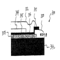
복수의 혼성 층들이 사용되는 경우에, 뒤이어 침착된 혼성 층은 밑에 놓인 혼성 층의 엣지들의 위에 연장되도록 만들어질 수 있다(즉, 뒤이어 침착된 혼성 층은 밑에 놓인 혼성 층보다 더 큰 커버리지 영역(footprint)을 가진다). 이 구성은 환경적인 오염물질들(예를 들어, 수분 또는 산소)의 측면 침입으로부터 혼성 층의 엣지들을 보호하기에 유용할 수 있다. 게다가, 다른 중합체 층들이 복수의 혼성 층들 사이에 배치될 수 있다. 예를 들어, 도21에 도시된 실시예를 참조하면, 전자 장치(240)는 기판(242)에 설치되는 OLED 몸체(244)(유기 층들의 스택을 포함)를 포함한다. OLED 몸체(244)는 OLED 몸체(244)의 엣지들의 위에 연장되는 제1 혼성 층(250)으로 코팅된다. 제1 혼성 층(250)은 중합체 층(254)으로 코팅되며, 그 다음에 중합체 층(254)의 엣지들 및 OLED 몸체(244)의 위에 연장되어 기판(242)의 표면과 접촉하는 제2 혼성 층(252)으로 코팅된다. 제1 혼성 층(250)의 엣지를 커버함으로써, 제2 혼성 층(252)은 제1 혼성 층(250)의 엣지로부터 나온 환경적인 오염물질들의 측면 침입을 방해하는 역할을 한다.If multiple hybrid layers are used, then the deposited hybrid layer can be made to extend over the edges of the underlying hybrid layer (i.e., the subsequently deposited hybrid layer will have a larger coverage area than the underlying hybrid layer ). This configuration may be useful for protecting the edges of the hybrid layer from side penetration of environmental contaminants (e.g., moisture or oxygen). In addition, other polymer layers may be disposed between the plurality of hybrid layers. 21,
혼성 층은 다양한 타입의 물품들의 위에 침착될 수 있다. 몇몇의 경우들에서, 물품은 OLED와 같은 유기 전자 장치일 수 있다. OLED에 대하여, 혼성 층은 수증기 및 산소의 침투에 저항하는 배리어 코팅으로 작용할 수 있다. 예를 들어, 10-6 g/m2/일보다 작은 수증기 투과율 및/또는 10-3 cm3/m2/일보다 작은(또는 몇몇의 경우들에는 10-4cm3/m2/일보다 작은) 산소 투과율을 가지는 혼성 층은 OLED들을 보호하기에 적합할 수 있다. 몇몇의 경우들에서, 혼성 층의 두께는 0.1에서부터 10 ㎛까지의 범위일 수 있지만, 다른 두께들도 또한 적용에 따라 사용될 수 있다. 또한, 광 투명성을 부여하는 두께 및 물질 조성을 가지는 혼성 층들은 OLED들에 사용하기에 적합할 수 있다. 유연한 OLED들에 사용하기 위해, 혼성 층은 원하는 양의 유연성을 가지도록 디자인될 수 있다. 몇몇의 경우들에서, 혼성 층은 의약품들, 의료 장치들이나 임플란트들, 생물학적 제제들, 생물학적 샘플들, 바이오센서들, 또는 민감한 측정 장치와 같은, 환경에 노출 시에 열화에 민감한 다른 물품들에 사용될 수 있다.The hybrid layer can be deposited on top of various types of articles. In some cases, the article may be an organic electronic device such as an OLED. For OLEDs, the hybrid layer can act as a barrier coating that resists penetration of water vapor and oxygen. For example less than 10 -6 g / m 2 / day and / or less than 10 -3 cm 3 / m 2 / day (or, in some cases, less than 10 -4 cm 3 / m 2 / day Small) oxygen transmission rate may be suitable for protecting the OLEDs. In some cases, the thickness of the hybrid layer may range from 0.1 to 10 microns, although other thicknesses may also be used depending on the application. In addition, hybrid layers having thickness and material composition that impart light transparency may be suitable for use in OLEDs. For use in flexible OLEDs, the hybrid layer can be designed to have the desired amount of flexibility. In some cases, the hybrid layer may be used in other articles that are sensitive to degradation upon exposure to the environment, such as pharmaceuticals, medical devices or implants, biological agents, biological samples, biosensors, or sensitive measurement devices .
몇몇의 경우들에서, 혼성 층은 또한 혼합되지 않은 중합체 층 또는 혼합되지 않은 비중합체 층과 같은, 전구체 물질의 동일한 단일 공급원을 사용함으로써 형성될 수 있는 혼합되지 않은 층과 함께 사용될 수 있다. 혼합되지 않은 층은 혼성 층이 침착되기 전에 또는 후에 침착될 수 있다.In some cases, the hybrid layer can also be used with an unmixed layer that can be formed by using the same single source of precursor material, such as an unmixed polymer layer or an unmixed nonpolymeric layer. The unmixed layer can be deposited before or after the hybridization layer is deposited.
어떤 다양한 타입의 CVD 반응기들이라도 본 발명의 방법들을 실행하기 위해 사용될 수 있다. 일 예로서, 도1은 본 발명의 몇몇의 실시예들을 실행하기 위해 사용될 수 있는 PE-CVD 장치(10)를 도시한다. PE-CVD 장치(10)는 반응 챔버(20)를 포함하며 전자 장치(30)는 홀더(24)에 탑재된다. 반응 챔버(20)는 진공을 가지도록 디자인되고 진공 펌프(70)는 적절한 압력을 생성시키며/시키거나 유지시키기 위해 반응 챔버(20)에 연결된다. N2 가스 탱크(50)는 장치(10)를 퍼징하기 위해 N2 가스를 제공한다. 반응 챔버(20)는 반응에 의해 생성된 열을 감소시키기 위해 냉각 시스템을 더 포함할 수 있다.Any of a variety of types of CVD reactors may be used to implement the methods of the present invention. As an example, FIG. 1 illustrates a PE-
가스들의 흐름을 통제하기 위해, 장치(10)는 또한 수동 또는 자동 제어될 수 있는 다양한 유동 제어 메커니즘들(질량 유동 제어기들(80), 셧오프 밸브들(shut-off valves)(82), 및 체크 밸브들(84) 등)을 포함한다. 전구체 물질 공급원(40)은 증발되어 반응 챔버(20)로 공급되는 전구체 물질(예를 들어, 액체 형태의 HMDSO)을 제공한다. 몇몇의 경우들에서, 전구체 물질은 아르곤과 같은 캐리어 가스를 사용하여 반응 챔버(20)로 이송될 수 있다. 반응물 가스 탱크(60)는 반응물 가스(예를 들어, 산소)를 제공하며, 이 반응물 가스는 또한 반응 챔버(20)로 공급된다. 전구체 물질과 반응물 가스는 반응 혼합물(42)을 생성시키기 위해 반응 챔버(20)로 유동된다. 전구체 물질과 반응물 가스는 반응 챔버(20)로 분리되어 유동될 수 있거나, 반응 챔버(20)에 들어가기 전에 미리 혼합될 수 있다. 반응 챔버(20) 내부의 압력은 침착 압력을 달성하기 위해 더 조절될 수 있다. 반응 챔버(20)는 도체들 또는 절연체들일 수 있는 전극 지지대들(standoffs)(26)에 설치되는 한 세트의 전극들(22)을 포함한다. 장치(30)와 전극들(22)의 다양한 배열이 가능하다. 다이오드(diode)나 트리오드(triode) 전극들, 또는 원격 전극들(remote electrodes)이 사용될 수 있다. 장치(30)는 도1에 도시된 바와 같이 이격되어 배치될 수 있거나, 다이오드 구성의 하나 또는 양쪽의 전극들에 설치될 수 있다.To control the flow of gases, the
전극들(22)은 반응 혼합물(42)에 플라스마 조건들을 생성시키기 위해 RF 전력을 공급받는다. 플라즈마에 의해 생성된 반응 생성물들은 전자 장치(30) 위에 침착된다. 반응은 전자 장치(30) 위에 혼성 층을 침착시키기에 충분한 시간 동안 진행되도록 허용된다. 반응 시간은 전극들(22)에 대한 장치(30)의 위치, 침착되는 혼성 층의 타입, 반응 조건들, 혼성 층의 원하는 두께, 전구체 물질, 및 반응물 가스와 같은 다양한 요소들에 따를 것이다. 반응 시간은 5 초 내지 5 시간 사이의 시간일 수 있지만, 더 길거나 더 짧은 시간도 또한 적용에 따라 사용될 수 있다.
아래의 표 1은 3가지 예의 혼성 층들을 만들기 위해 사용된 반응 조건들을 보여준다. 예 1의 혼성 층은, 물방울들의 습윤 접촉각으로부터 측정될 때, 대략 7% 중합체 물질과 93% 비중합체 물질을 함유하였다. 예 2의 혼성 층은, 물방울들의 습윤 접촉각으로부터 측정될 때, 대략 94% 중합체 물질과 6% 비중합체 물질을 함유하였다. 예 3의 혼성 층은, 물방울들의 습윤 접촉각으로부터 측정될 때, 대략 25% 중합체 물질과 75% 비중합체 물질을 함유하였다. 예 1 내지 예 3의 각각에서, 반응 조건들이 침착 공정의 전체에 걸쳐 일정하게 유지되었다면, 혼성 층은 전체에 걸쳐 균질의 조성을 가지는 단일 상으로 존재한다. 또한 예 1 내지 예 3에 의해 보여지는 바와 같이, 혼성 층은 적어도 800 Å의 두께에 걸쳐, 그리고 몇몇의 경우들에는, 800 Å 내지 60,000 Å 범위의 두께에 걸쳐 균질의 조성을 가지는 단일 상으로 존재할 수 있다. 그러나, 다른 실시예들에서, 위에 설명된 방식으로 반응 조건들을 변졍함으로써, 혼성 층은 각각이 상이한 조성을 가지는, 다수의 상이한 하위층들(sublayers)에 의한 다수의 상들을 가질 수 있다.Table 1 below shows the reaction conditions used to make the three examples of hybrid layers. The hybrid layer of Example 1 contained approximately 7% polymeric material and 93% non-polymeric material, as measured from the wet contact angle of water droplets. The hybrid layer of Example 2 contained approximately 94% polymeric material and 6% non-polymeric material, as measured from the wet contact angle of water droplets. The hybrid layer of Example 3 contained approximately 25% polymeric material and 75% non-polymeric material, as measured from the wet contact angle of water droplets. In each of Examples 1 to 3, if the reaction conditions were kept constant throughout the deposition process, the hybrid layer was present as a single phase having a homogeneous composition throughout. Also as shown by Examples 1 to 3, the hybrid layer can be present in a single phase having a homogeneous composition over a thickness of at least 800 ANGSTROM, and in some cases, in the range of 800 ANGSTROM to 60,000 ANGSTROM have. However, in other embodiments, by varying the reaction conditions in the manner described above, the hybrid layer can have multiple phases, each with a different composition, by a number of different sublayers.
(m torr)pressure
(m torr)
(W)RF power
(W)
시간
(분)composure
time
(minute)
(Å)Film thickness
(A)
도2는 예 3의 혼성 층의 광 투과 스펙트럼을 보여준다. 이 혼성 층은 근자외선 스펙트럼에서부터 근적외선 스펙트럼까지 90%보다 더 큰 투과율을 가진다. 도3은 필름 위에서 물방울의 접촉각이 어떻게 측정되는지를 보여준다. 도4는 순수 SiO2 필름 및 순수 중합체 필름의 접촉각들과 비교하여 다양한 O2/HMDSO 가스 유동 비율들 하에서 형성되는 몇몇 혼성 층들의 접촉각들의 선도이다. 혼성 층들의 접촉각들은 침착 공정에서 산소 유량이 증가함에 따라 순수 SiO2 필름의 접촉각에 근접한다.Fig. 2 shows the light transmission spectrum of the hybrid layer of Example 3. Fig. This hybrid layer has a transmittance greater than 90% from the near-ultraviolet spectrum to the near-infrared spectrum. Figure 3 shows how the contact angle of water droplets on the film is measured. Figure 4 is a plot of the contact angles of several hybrid layers formed under various O 2 / HMDSO gas flow ratios as compared to the contact angles of the pure SiO 2 film and the pure polymer film. The contact angles of the hybrid layers approach the contact angle of the pure SiO 2 film as the oxygen flow rate increases in the deposition process.
도5는 PE-CVD 공정 중에 가해진 다양한 전력 레벨 하에서 형성되는 몇몇 혼성 층들의 접촉각들의 선도이다. 혼성 층들의 접촉각들은 전력 레벨이 증가함에 따라 순수 SiO2 필름의 접촉각에 근접하며, 이는 더 높은 전력 레벨이 O2를 더 강한 산화제로 만든다는 사실에 기인한 것일 수 있다. 도6은 순수 SiO2(열산화물) 또는 순수 중합체의 필름들과 비교하여 상대적으로 높은 O2 유동 및 상대적으로 낮은 O2 유동을 사용하여 형성되는 혼성 층들의 적외선 흡수 스펙트럼을 보여준다. 높은 O2 혼성 층은 Si-O-Si 밴드에서 강한 피크들을 보여준다. 열산화물(순수 SiO2) 필름에 대한 Si-CH3 밴드의 공칭 피크들은 Si-O 진동들과 관련되는 것으로 믿어지고 있다. 도7은 순수 SiO2 필름의 경도와 비교하여 다양한 O2/HMDSO 가스 유동 비율들 하에서 형성되는 다양한 혼성 층들의 나노 인덴테이션 경도의 선도이다. 혼성 층들의 경도는 침착 공정에서 산소 유량이 증가함에 따라 증가하며, 이 혼성 층들은 순수 SiO2 필름들만큼 단단할 수 있으며, 그러면서도 질기며 매우 유연할 수 있다.5 is a diagram of the contact angles of some of the hybrid layers formed at various power levels applied during the PE-CVD process. The contact angles of the hybrid layers approach the contact angle of the pure SiO 2 film as the power level increases, which may be due to the fact that higher power levels make O 2 a stronger oxidizing agent. Figure 6 shows the infrared absorption spectra of the hybrid layers formed using relatively high O 2 flow and relatively low O 2 flow compared to films of pure SiO 2 (thermal oxide) or pure polymer. The high O 2 hybrid layer shows strong peaks in the Si-O-Si band. Nominal peak of the Si-CH 3 bands on the thermal oxide (pure SiO 2) film are believed to be associated with SiO vibration. 7 is a diagram of a nano-indentation hardness of various hybrid layers formed under various O 2 / HMDSO gas flow ratios in comparison to the hardness of a pure SiO 2 film. The hardness of the hybrid layers increases as the oxygen flow rate increases in the deposition process, and these hybrid layers can be as hard as pure SiO 2 films, while still being tough and very flexible.
도8은 원자력 현미경에 의해 측정된, 다양한 02/HMDS0 가스 유동 비율들 하에서 형성되는 몇몇 혼성 층들의 표면 조도(평균제곱근)의 선도이며, 침착 공정에 사용되는 O2 유량들이 증가하면 표면 조도가 감소한다는 것을 보여준다. 도9는 원자력 현미경에 의해 측정된, 다양한 전력 레벨 하에서 형성되는 몇몇 혼성 층들의 표면 조도(평균제곱근)의 선도이며, 침착 공정에 사용되는 전력 레벨이 증가하면 표면 조도가 감소한다는 것을 보여준다.Figure 8 is a graph of the surface roughness (mean square root) of several mixed layers formed under various O 2 / HMDSO gas flow ratios, as measured by atomic force microscopy. As the O 2 flow rates used in the deposition process increase, the surface roughness Respectively. Figure 9 is a plot of surface roughness (mean square root) of several hybrid layers formed at various power levels, as measured by atomic force microscopy, showing that as the power level used in the deposition process increases, surface roughness decreases.
도10a 및 도10b는 50 ㎛ 두께의 캡톤 폴리이미드 호일 위의 4 ㎛ 혼성 층(위의 예 3과 동일한 공급원 온도, 가스 유량, 압력 및 RF 전력 하에서 침착된)의 표면의 광학 현미경 사진들을 보여준다. 도10a에서, 이미지들은 코팅된 호일이 1 인치 직경의 롤(인장 변형률 ε = 0.2%)에서 사이클릭 롤링을 받기 전과 후에 획득되었다. 미세 구조적 변화가 58,600 롤링 사이클 후에도 관찰되지 않았다. 도10b에서, 코팅된 호일은 인장 변형률의 증가를 받았으며, 이미지들은 제1 크래킹(14 ㎜의 롤 직경)의 발생 후에 그리고 다량의 크래킹(2 ㎜의 롤 직경) 후에 획득되었다. 이 유연성의 결과들은 본 발명의 방법들이 매우 유연한 코팅을 제공할 수 있다는 것을 증명한다.10A and 10B show optical micrographs of the surface of a 4 탆 hybrid layer on a 50 탆 thick Capton polyimide foil (deposited at the same source temperature, gas flow rate, pressure and RF power as in Example 3 above). In Fig. 10a, images were obtained before and after the coated foil was subjected to cyclic rolling at 1 inch diameter rolls (tensile strain? = 0.2%). No microstructural changes were observed after 58,600 rolling cycles. In Figure 10b, the coated foil was subjected to an increase in tensile strain and images were obtained after the generation of the first cracking (roll diameter of 14 mm) and after a large amount of cracking (roll diameter of 2 mm). The results of this flexibility demonstrate that the methods of the present invention can provide very flexible coatings.
도11은 기판(150) 위에 있는 OLED 몸체(140), 및 배리어 코팅(110)으로서 위의 예 3의 혼성 층을 포함하는 캡슐화된 OLED(100)의 일 부분의 단면도를 도시한다. 도12는 배리어 코팅들을 가지는 완전한 OLED들의 가속 환경 테스트들의 결과들을 보여준다. 저면 발광 OLED들 및 투명 OLED들 모두가 예 3의 6 ㎛ 두께 혼성 층으로 코팅되었다. 그 다음에 이 장치들은 65℃ 와 85% 상대 습도에서 환경 챔버에 저장되었다. 이미지들은 초기 시점에서와 지시된 시간 간격들 이후의 OLED들의 상태를 보여준다. OLED들은, 본 발명의 방법들이 환경 노출의 열화의 영향들에 대하여 효과적으로 보호하는 코팅을 제공할 수 있다는 것을 증명하면서, 1000 시간이 훨씬 지난 후에도 계속해서 기능을 하였다.11 shows a cross-sectional view of a portion of an encapsulated
혼성 층이 전자 장치에 대한 환경 배리어로서 사용되는 경우들에서, 혼성 층은 전자 장치가 배치되는 표면으로서, 전자 장치에 대한 커버로서, 또는 둘 모두로서 작용할 수 있다. 예를 들어, 하나의 혼성 층은 전자 장치를 커버하기 위해 전자 장치 위에 침착될 수 있으며 다른 혼성 층은 전자 장치가 배치되는 표면을 제공하기 위해 전자 장치 하부에 있는 기판 위에 침착될 수 있다. 이런 방식으로, 전자 장치는 2개의 혼성 층들 사이에 밀봉된다.In instances where the hybrid layer is used as an environmental barrier for an electronic device, the hybrid layer may act as a surface on which the electronic device is placed, as a cover for an electronic device, or both. For example, one hybrid layer may be deposited over the electronic device to cover the electronic device, and another hybrid layer may be deposited over the substrate below the electronic device to provide a surface on which the electronic device is disposed. In this way, the electronic device is sealed between the two hybrid layers.
예를 들면, 도13에 도시된 실시예를 참조하면, 캡슐화된 OLED(160)는 그의 위에 침착된 혼성 층(162)을 가지는 기판(150)을 포함한다. OLED(전극들을 포함)의 몸체(140)는 혼성 층(162)의 표면 위에 배치된다. 혼성 층(162)과 동일한 조성을 가지거나 가지지 않을 수 있는 다른 혼성 층(164)은 콘포멀 코팅(conformal coating)으로서 OLED 몸체(140) 위에 침착된다. 이와 같이, OLED 몸체(140)의 상부를 커버하는 것에 추가하여, 혼성 층(164)은 또한 OLED 몸체(140)의 측면들의 아래로 연장되며 혼성 층(162)의 표면과 접촉한다. 이런 방식으로, OLED 몸체(140)는 혼성 층(162)과 혼성 층(164) 사이에 끼이게 된다.For example, referring to the embodiment shown in FIG. 13, an encapsulated OLED 160 includes a
몇몇 실시예들에서, 혼성 층이 침착되는 표면은 이 표면과 혼성 층 사이의 계면 접착력을 증가시키기 위해 혼성 층을 침착시키기 전에 전처리될 수 있다. 표면 전처리는 표면의 접착력의 향상, 표면 화학성의 개질(예를 들어, 표면 활성화), 표면 조도의 변경, 표면 에너지의 증가, 표면의 평탄화, 및/또는 표면의 청결화를 포함하는 다양한 표면 특성들을 변경시킬 수 있다. 표면과 혼성 층 사이의 계면 접착력을 증가시킴으로써, 이 특징이 혼성 층의 엣지들로부터 환경 오염물질들(수분 또는 산소와 같은)의 측면 확산을 감소시키기에 유용할 수 있다.In some embodiments, the surface on which the hybrid layer is deposited may be pretreated prior to depositing the hybrid layer to increase the interfacial adhesion between the surface and the hybrid layer. The surface pretreatment may include various surface properties, including improvement of surface adhesion, modification of surface chemistry (e.g., surface activation), alteration of surface roughness, increase of surface energy, surface planarization, and / Can be changed. By increasing the interfacial adhesion between the surface and the hybrid layer, this feature may be useful for reducing lateral diffusion of environmental contaminants (such as moisture or oxygen) from the edges of the hybrid layer.
기계적 마모, 화학적 처리들(예를 들어, 산화제들에 대한 노출, 작용기들의 도입에 의한 활성화) 또는 물리화학적 처리들(예를 들어, 플라즈마에 대한 노출, 코로나 방전, 또는 UV 조사)을 포함하는, 표면과 혼성 층 사이의 계면 접착력을 증가시킬 수 있는 다양한 타입의 표면 처리들이 본 발명에서 사용하기에 적합하다. 플라즈마 처리가 사용되는 경우에, 처리는 혼성 층을 침착시키기 위해 사용되는 동일한 챔버에서 실행될 수 있거나, 플라즈마 처리는 별도의 장치에서 실행될 수 있으며, 이 경우에, 배럴 타입 플라즈마 시스템들과 평행판 타입의 플라즈마 시스템들을 포함하여, 본 기술분야에 공지된 다양한 타입의 플라즈마 처리 장치들 중 어떤 것이라도 사용될 수 있다.Including mechanical abrasion, chemical treatments (e.g., exposure to oxidants, activation by introduction of functional groups) or physicochemical treatments (e.g. exposure to plasma, corona discharge, or UV radiation) Various types of surface treatments that can increase the interfacial adhesion between the surface and the hybrid layer are suitable for use in the present invention. In the case where a plasma treatment is used, the treatment may be carried out in the same chamber used to deposit the hybrid layer, or the plasma treatment may be carried out in a separate apparatus, in which case the barrel type plasma systems and the parallel plate type Any of a variety of types of plasma processing apparatuses known in the art, including plasma systems, may be used.
산소, 수소, 질소, 아르곤, 암모니아, 또는 이들의 혼합물들과 같은 가스들을 포함하여, 종래에 플라즈마 처리들에 사용된 다양한 가스들 중 어떤 것이라도 표면을 전처리하기에 적합할 수 있다. 특히 바람직한 가스들은 산소 및 아르곤을 포함한다. 다른 가스들이 상이한 방식으로 표면을 개질하기 위해 사용될 수 있다. 예를 들어, 아르곤 가스를 사용한 플라즈마 처리는 아르곤 이온들로 표면에 충격을 가할 것이며, 이는 표면을 청결하게 할 수 있거나 원자 스케일에서 표면을 더 거칠게 만들어, 혼성 층에 부착되는 성능을 개선시킬 수 있다. 산소를 사용한 플라즈마 처리는 산소 함유 작용기들로 표면을 화학적으로 활성화시킬 수 있으며, 이는 혼성 층과 결합들을 형성할 수 있다. 원하는 표면 특성을 얻기 위해, 전력, 주파수, 지속시간, 압력, 또는 온도를 포함하는, 플라즈마 처리 공정의 다양한 다른 파라미터들이 조절될 수 있다.Any of the various gases conventionally used in plasma treatments, including gases such as oxygen, hydrogen, nitrogen, argon, ammonia, or mixtures thereof, may be suitable for pretreating the surface. Particularly preferred gases include oxygen and argon. Other gases can be used to modify the surface in different ways. For example, a plasma treatment with argon gas will impact the surface with argon ions, which can clean the surface or make the surface rougher at the atomic scale, improving the ability to adhere to the hybrid layer . Plasma treatment with oxygen can chemically activate the surface with oxygen-containing functional groups, which can form bonds with the hybrid layer. Various other parameters of the plasma processing process, including power, frequency, duration, pressure, or temperature, may be adjusted to achieve the desired surface properties.
몇몇의 경우들에서, 표면은 표면과 혼성 층 사이에 개재 층을 배치함으로써 전처리될 수 있다. 개재 층은 표면과 혼성 층 사이의 계면 접착력을 개선시키도록 작용할 수 있는 다양한 임의의 물질들을 포함한다. 예를 들어, 개재 층에 사용하기에 적합한 물질들은 질화실리콘, 크롬, 티타늄, 니켈-티타늄 합금, 또는 유전체 물질을 포함한다. 이 층은 화학 증착, 플라즈마 증착 또는 스퍼터링을 포함하는, 종래에 얇은 필름들의 침착에 사용되는 다양한 기술들을 사용하여 침착될 수 있다. 개재 층의 두께는 특정한 적용에 따라 바뀔 것이다. 몇몇의 경우들에서, 개재 층은 단일 원자 또는 단일 분자 층일 수 있거나, 또는 50 ㎚까지의 두께를 가질 수 있지만, 다른 경우에는 상이한 두께들도 또한 가능하다. 개재 층의 물질은 개재 층의 위나 아래에 있는 층들 또는 구조물의 물질들과 추가로 화학 반응을 할 수 있다.In some cases, the surface can be pretreated by placing an intervening layer between the surface and the hybrid layer. The intervening layer includes any of a variety of materials that can act to improve interfacial adhesion between the surface and the hybrid layer. For example, materials suitable for use in the interlayer include silicon nitride, chromium, titanium, nickel-titanium alloys, or dielectric materials. This layer can be deposited using a variety of techniques conventionally used for deposition of thin films, including chemical vapor deposition, plasma deposition or sputtering. The thickness of the interlayer will vary depending on the particular application. In some cases, the intervening layer can be a single atom or single molecule layer, or it can have a thickness up to 50 nm, but in other cases different thicknesses are also possible. The material of the intervening layer may further chemically react with the materials of the layers or structures above or below the intervening layer.
도14는 에칭된 실리콘 웨이퍼 위에 침착된 혼성 층의 단면의 주사 전자 현미경 사진(SEM)을 보여준다. 실리콘 웨이퍼의 에칭되지 않은 부분(5 ㎛ 단차 높이를 가지는 융기된 엣지로서 도14의 좌측에 도시된)은 80 ㎚ 크롬 필름으로 커버되었으며, 이는 또한 실리콘 웨이퍼의 에칭 중에 에칭 마스크로서 기능을 하였다. 실리콘 웨이퍼의 에칭된 부분(도14의 우측에 도시된)은 크롬 필름으로 전처리되지 않았다. 혼성 층은 다음의 조건들 하에서 실리콘 웨이퍼의 양쪽 모두의 부분들의 위에 PE-CVD에 의해 침착되었다:14 shows a scanning electron micrograph (SEM) of a cross-section of a hybrid layer deposited on an etched silicon wafer. The unetched portion of the silicon wafer (shown in the left-hand side of FIG. 14 as a raised edge with a 5 um step height) was covered with 80 nm chromium film, which also served as an etching mask during etching of the silicon wafer. The etched portions of the silicon wafer (shown on the right in Fig. 14) were not pretreated with chromium film. The hybrid layer was deposited by PE-CVD on both portions of the silicon wafer under the following conditions:
* 각각 25분의 2회의 간헐적인 시간에서, 각각의 시간 사이에 냉각됨.* Cooled between each time, in two-twenty-two intermittent times each.
간헐적인 침착 공정의 가열 및 냉각 사이클들을 통과한 실리콘 웨이퍼 기판의 평균 온도는 80℃(약 22℃의 시작 온도 및 약 160℃의 종료 온도를 가지는)보다 높았다. 크롬 처리된 표면 위에, 혼성 층은 치밀한 미세 구조를 가졌다. 그러나, 처리되지 않은 표면 위에, 배리어 층은 불규칙한, 원주형의 미세 구조를 가졌다. 형태학적 차이들에 기초하여, 크롬 처리된 표면(치밀한 미세 구조를 갖는) 위에 있는 혼성 층은 처리되지 않은 표면 위에 침착된 혼성 층보다 수분과 산소에 의해 보다 적게 투과될 것으로 예상될 수 있다.The average temperature of the silicon wafer substrate through the heating and cooling cycles of the intermittent deposition process was higher than 80 占 폚 (with a starting temperature of about 22 占 폚 and an ending temperature of about 160 占 폚). On the chrome treated surface, the hybrid layer had dense microstructure. However, on the untreated surface, the barrier layer had an irregular, columnar microstructure. Based on the morphological differences, the hybrid layer on the chromed surface (with dense microstructure) can be expected to be less permeable by moisture and oxygen than the hybrid layer deposited on the untreated surface.
몇몇의 경우들에서, 개재 층은 하나 이상의 평탄화 하위층들 및 하나 이상의 접착 촉진 하위층들을 포함하는 다층 구조일 수 있다. 예를 들어, 미국 특허 제6,597,111호(Silvernail 등)와 미국 특허 제7,187,119호(Weaver)는 교호하는 일련의 중합체 평탄화 하위층들 및 고밀도 하위층들로 형성되는 배리어 층들을 설명하고 있다. 중합체 평탄화 하위층은 매끄러운 표면을 형성하는 중합체 평탄화 물질을 포함한다. 고밀도 하위층은 환경 오염물질들의 확산이 방해될 정도로 충분히 가까운 원자 간격을 가지는 고밀도 물질(예를 들어, 무기, 세라믹, 또는 유전체 물질)을 포함한다. 다른 예에서, 개재 층은 스핀 코팅된(spin-coated) 중합체 층들 및 혼성 층들(위에 설명된 방식으로 침착된); 또는 SiNx 층들 및 혼성 층들; 또는 스핀 코팅된 중합체 층들 및 SiNx 층들의 다수의 교호하는 층들을 포함할 수 있다.In some cases, the intervening layer may be a multi-layer structure comprising one or more planarizing sub-layers and one or more adhesion promoting sub-layers. For example, U.S. Patent No. 6,597,111 (Silvernail et al.) And U.S. Patent No. 7,187,119 (Weaver) describe alternating series of polymer planarization sublayers and barrier layers formed of high density sublayers. The polymeric planarizing sublayer includes a polymeric planarizing material that forms a smooth surface. The high density sublayer includes a high density material (e.g., inorganic, ceramic, or dielectric material) having atom spacings sufficiently close to the diffusion of environmental contaminants. In another example, the intervening layer comprises spin-coated polymeric layers and hybrid layers (deposited in the manner described above); Or SiN x layers and hybrid layers; Or spin-coated polymer layers and a plurality of alternating layers of SiN x layers.
예를 들어, 도15에 도시된 실시예를 참조하면, 전자 장치(176)는 중합체 물질의 평탄화 하위층(170)으로 코팅되는 기판(150)을 포함한다. 접착 촉진 하위층(172)은 평탄화 하위층(170)의 위에 배치된다. OLED(전극들을 포함하는)의 몸체(140)는 접착 촉진 하위층(172)의 표면 위에 배치된다. 그 다음에 혼성 층(174)이 콘포멀 코팅으로서 OLED 몸체(140)의 위에 침착된다. 이와 같이, OLED 몸체(140)의 상부를 커버하는 것에 추가하여, 혼성 층(174)은 또한 OLED 몸체(140)의 측면들의 하부로 연장되며 접착 촉진 하위층(172)의 표면과 접촉한다. 이런 방식으로, 혼성 층(174)과 접착 촉진 하위층(172) 사이의 접착은 계면 영역을 통한 환경 오염물질들의 측면 확산을 감소시킬 수 있다.For example, referring to the embodiment shown in FIG. 15, an
위에 설명된 바와 같이, 침착 조건들은 상이한 구조들, 조성들, 및/또는 환경 오염물질들에 대한 투과성 및 혼성 층이 침착된 표면에 접착되는 능력을 포함하는 특성들을 가지는 혼성 층들을 제공하기 위해 변경될 수 있다. 몇몇의 경우들에서, 침착 온도(예를 들어, 기판의 가열과 냉각을 통해)는 혼성 층의 투과성을 감소시키도록 제어될 수 있다. 도16A 및 도16B는 에칭된 실리콘 웨이퍼의 위에 침착된 혼성 층의 단면의 주사 전자 현미경 사진(SEM)을 보여준다. 실리콘 웨이퍼의 에칭되지 않은 부분(융기된 엣지로서 도16A 및 도16B의 우측에 도시된)은 얇은 크롬 필름으로 커버되었으며, 이는 또한 실리콘 웨이퍼의 에칭 중에 에칭 마스크로서 기능을 하였다. 실리콘 웨이퍼의 에칭된 부분(도16A 및 도16B의 좌측에 도시된)은 얇은 크롬 필름으로 전처리되지 않았다. 혼성 층은 다음의 조건들 하에서 PE-CVD에 의해 실리콘 웨이퍼의 양쪽 부분들의 위에 침착되었다:As described above, the deposition conditions can be varied to provide hybrid layers with properties including the permeability to different structures, compositions, and / or environmental contaminants and the ability of the hybrid layer to adhere to the deposited surface . In some cases, the deposition temperature (e.g., through heating and cooling of the substrate) can be controlled to reduce the permeability of the hybrid layer. 16A and 16B show a scanning electron micrograph (SEM) of a cross-section of a hybrid layer deposited on top of an etched silicon wafer. The unetched portions of the silicon wafer (shown in the right-hand side of Figs. 16A and 16B as raised edges) were covered with a thin chromium film, which also served as an etching mask during etching of the silicon wafer. The etched portions of the silicon wafer (shown in the left side of Figs. 16A and 16B) were not pretreated with thin chromium film. The hybrid layer was deposited on both sides of the silicon wafer by PE-CVD under the following conditions:
* 각각 5분의 16회의 간헐적인 시간에서, 각각의 시간 사이에 냉각됨.* Cooled between each time, at 16 intermittent times of 16/5.
간헐적인 침착 공정의 가열 및 냉각 사이클들을 통과한 실리콘 웨이퍼 기판의 평균 온도는 약 35℃이었다. 간헐적인 침착 공정에서, 침착 온도를 제어하는 하나의 방식은 가열의 수 또는 시간 및/또는 사이클들을 조절하는 것이다. 이와 같이, 이 혼성 층은 더 짧은 시간의 가열 사이클들 및 더 많은 수의 냉각 사이클들로 침착되었기 때문에, 평균 침착 온도는 도14에 도시된 혼성 층을 침착시키기 위해 사용된 온도보다 더 낮았다. 결과적으로, 실리콘 웨이퍼의 크롬 처리된 표면과 처리되지 않은 표면(bare surface) 양쪽 모두의 위에 있는 혼성 층은 불규칙한, 원주형의 미세 구조를 가진다. 또한, 단차의 측면들의 위에는 빈약한 커버리지(coverage)가 있다. 따라서, 일정 범위 내의 더 높은 침착 온도를 사용하여 형성된 혼성 층은 더 낮은 침착 온도를 사용하여 형성된 혼성 층보다 더 낮은 투과성을 가질 것으로 예상될 수 있다. 몇몇의 경우들에서, 혼성 층은 40℃ 내지 90℃의 범위에 있는 침착 온도 하에서 침착된다.The average temperature of the silicon wafer substrate through the heating and cooling cycles of the intermittent deposition process was about 35 ° C. In an intermittent deposition process, one way to control the deposition temperature is to control the number of times or times and / or cycles of heating. Thus, the average deposition temperature was lower than the temperature used to deposit the hybrid layer shown in Figure 14, because this hybrid layer was deposited with shorter time heating cycles and a greater number of cooling cycles. As a result, the hybrid layer on both the chrome-treated surface and the bare surface of the silicon wafer has an irregular, columnar microstructure. There is also poor coverage over the sides of the steps. Thus, a hybrid layer formed using a higher deposition temperature within a certain range can be expected to have a lower permeability than a hybrid layer formed using a lower deposition temperature. In some cases, the hybrid layer is deposited under a deposition temperature in the range of 40 占 폚 to 90 占 폚.
몇몇의 경우들에서, 침착 전력은 혼성 층의 투과성을 감소시키기 위해 제어될 수 있다. 도17A는 저면 발광 OLED 스택 위에 침착된 혼성 층의 단면의 주사 전자 현미경 사진(SEM)을 보여준다. 혼성 층은 다음의 조건들 하에서 PE-CVD에 의해 침착되었다:In some cases, the deposition power can be controlled to reduce the permeability of the hybrid layer. 17A shows a scanning electron micrograph (SEM) of a cross-section of a hybrid layer deposited on a bottom-emitting OLED stack. The hybrid layer was deposited by PE-CVD under the following conditions:
* 다음의 간헐적인 시간들에서: 100 mTorr에서 9분, 뒤이어서 100 mTorr에서 8회 6분, 뒤이어서 130 mTorr에서 8분, 뒤이어서 150 mTorr에서 10분, 뒤이어서 125 mTorr에서 9분, 뒤이어서 150 mTorr에서 7분, 뒤이어서 125 mTorr에서 8분, 뒤이어서 150 mTorr에서 10분, 뒤이어서 125 mTorr에서 8분, 및 뒤이어서 125 mTorr에서 9분.In the following intermittent times: 9 min at 100 mTorr, followed by 8 min at 100 mTorr followed by 8 min at 130 mTorr followed by 10 min at 150 mTorr followed by 9 min at 125 mTorr followed by 7 min at 150 mTorr Min followed by 8 min at 125 mTorr followed by 10 min at 150 mTorr followed by 8 min at 125 mTorr followed by 9 min at 125 mTorr.
더 높은 침착 전력은 단량체 분열을 향상시키는 것으로 믿어지고 있다. 따라서, 24 W에서부터 50 W까지 전력을 점차 증가시킴으로써, 혼성 층에 있는 각각의 뒤이어지는 계층은 더 많은 산화물 유사 특성 및 더 적은 중합체 유사 특성을 띠는 것으로 관찰된다. 도17A에서, 표면에 가장 가까운 혼성 층의 계층(더 낮은 전력 하에서 침착된)은 다공성의, 중합체 유사 미세 구조를 가지며, 표면으로부터 보다 멀리 떨어진 계층(더 높은 전력 하에서 침착된)은 더 치밀한, 산화물 유사 미세 구조를 가진다.It is believed that higher deposition power improves monomer fragmentation. Thus, by gradually increasing the power from 24 W to 50 W, it is observed that each subsequent layer in the hybrid layer has more oxide-like and less polymer-like properties. In FIG. 17A, the layer of the hybrid layer closest to the surface (deposited under lower power) has a porous, polymer-like microstructure, and a layer further away from the surface (deposited under higher power) Have a pseudo-microstructure.
도17B는 다음의 조건들 하에서 상면 발광 OLED 스택의 위에 PE-CVD에 의해 침착된 다른 혼성 층의 단면의 주사 전자 현미경 사진(SEM)을 보여준다:17B shows a scanning electron micrograph (SEM) of a cross-section of another hybrid layer deposited by PE-CVD on top of the top-emitting OLED stack under the following conditions:
(mTorr)pressure
(mTorr)
* 각각 10분의 12회의 간헐적인 시간에서, 각각의 시간 사이에 냉각됨.* Cooled between each of the twelve tenths of an intermittent time, respectively.
도17A에 도시된 혼성 층과 비교하여, 더 높은 침착 전력이 도17B에 도시된 혼성 층을 침착시키기 위해 사용되었다. 결과적으로, 이 혼성 층은 도17A에 도시된 혼성 층의 미세 구조보다 더 치밀한 미세 구조를 가진다. 따라서, 더 높은 침착 전력을 사용하여 형성된 혼성 층은 더 낮은 침착 전력을 사용하여 형성된 혼성 층보다 더 낮은 투과성을 가지는 것으로 예상될 수 있다.In contrast to the hybrid layer shown in Figure 17A, higher deposition power was used to deposit the hybrid layer shown in Figure 17B. As a result, this hybrid layer has a more dense microstructure than the microstructure of the hybrid layer shown in Fig. 17A. Thus, a hybrid layer formed using higher deposition power can be expected to have lower permeability than a hybrid layer formed using lower deposition power.
2개의 유사하지 않은 물질들이 서로 긴밀히 접촉되게 배치되는 경우에, 이와 같은 접촉은 특히 2개의 물질들 사이의 계면에서 응력들을 일으킬 수 있다. 따라서, 몇몇 실시예들에서, 혼성 층의 잔류 내부 응력은 크래킹, 보이드(void), 버클링(buckling), 또는 박리(delamination)와 같은, 혼성 층의 응력 유도 결함들의 발생을 감소시키기 위해 제어될 수 있다. 혼성 층의 내부 응력을 제어하는 하나의 방식은 침착 조건들을 조절하는 것이다.In the case where two dissimilar materials are arranged in intimate contact with each other, such contact can cause stresses, especially at the interface between the two materials. Thus, in some embodiments, the residual internal stress of the hybrid layer is controlled to reduce the occurrence of stress induced defects in the hybrid layer, such as cracking, voiding, buckling, or delamination . One way to control the internal stress of the hybrid layer is to adjust the deposition conditions.
도18A 내지 도18C는 25 ㎛ 두께의 캡톤-E 폴리이미드 기판들과 상이한 조건들 하에서 그의 위에 침착된 다양한 혼성 층들(320 내지 600 ㎚ 두께의) 사이의 변형률 미스매치들을 보여준다. 양의 미스매치들은 혼성 층의 인장 응력에 상응하며 음의 미스매치들은 혼성 층의 압축 응력에 상응한다. 도18A를 참조하면, 침착 전력 및 가스 유량이 일정하게 유지되면서 100 mTorr에서부터 150 mTorr까지 침착 압력을 증가시킴으로써 더 큰 인장 응력이 혼성 층에서 생성되는 결과를 초래한다. 도18B를 참조하면, 침착 압력 및 가스 유량이 일정하게 유지되면서, 50 W에서부터 80 W까지 침착 전력을 증가시킴으로써 더 큰 압축 응력이 혼성 층에서 생성되는 결과를 초래한다. 도18C를 참조하면, 침착 압력 및 전력이 일정하게 유지되면서, 1.0/34에서부터 2.0/67까지 HMDSO/O2 가스 유량을 증가시킴으로써 더 큰 인장 응력이 혼성 층에서 생성되는 결과를 초래한다.Figures 18A-18C show strain mismatches between various hybrid layers (320 to 600 nm thick) deposited on top of 25 um thick Capton-E polyimide substrates under different conditions. Positive mismatches correspond to tensile stresses in the hybrid layer and negative mismatches correspond to compressive stresses in the hybrid layer. Referring to FIG. 18A, increasing deposition pressure from 100 mTorr to 150 mTorr while maintaining constant deposition power and gas flow rate results in greater tensile stress being produced in the hybrid layer. Referring to FIG. 18B, increasing deposition power from 50 W to 80 W results in greater compressive stress being produced in the hybrid layer, while the deposition pressure and gas flow rate remain constant. Referring to FIG. 18C, increasing the HMDSO / O 2 gas flow rate from 1.0 / 34 to 2.0 / 67, while maintaining the deposition pressure and power constant, results in greater tensile stress being produced in the hybrid layer.
이 결과들은 혼성 층의 내부 응력이 침착 파라미터들을 변경시킴으로써 조정될 수 있다는 것을 나타낸다. 이 결과들은 또한 혼성 층의 응력이 최소화될 수 있는 침착 파라미터들의 최적의 세트가 있다는 것을 나타낸다. 예를 들어, 하나의 침착 파라미터는 혼성 층의 압축 응력을 생성하기 위해 조정될 수 있으며 다른 침착 파라미터는 혼성 층의 매칭하는 인장 응력을 생성하기 위해 조정될 수 있으며, 0 또는 0에 가까운 잔류 순 응력을 초래한다. 다층 코팅이 복수의 혼성 층들을 포함하는 경우에, 코팅의 전체 응력을 제어하기 위해 각각의 혼성 층의 응력을 또한 개별적으로 조정할 수 있다. 예를 들어, 각각의 혼성 층은 코팅의 전체 응력의 평형을 유지하기 위해, 또는 표면으로부터의 거리를 증가시킴과 함께 혼성 층의 응력의 양을 점차 증가시키기 위해 조정될 수 있다.These results indicate that the internal stress of the hybrid layer can be adjusted by changing the deposition parameters. These results also indicate that there is an optimal set of deposition parameters that can minimize the stress of the hybrid layer. For example, one deposition parameter can be adjusted to produce the compressive stress of the hybrid layer and the other deposition parameters can be adjusted to produce a matching tensile stress of the hybrid layer, resulting in a net residual stress near zero or zero do. In the case where the multilayer coating comprises a plurality of hybrid layers, the stresses of each hybrid layer can also be individually adjusted to control the overall stress of the coating. For example, each hybrid layer can be adjusted to maintain an equilibrium of the total stress of the coating, or to gradually increase the amount of stress in the hybrid layer, increasing the distance from the surface.
서로 긴밀히 접촉되게 배치되는 2개의 유사하지 않은 물질들은 또한 상이한 열팽창 계수들(CTE)로부터 생기는 잔류 응력들을 일으킬 수 있다. 따라서, 몇몇 실시예들에서, 혼성 층의 조성은 인접한 구조(예를 들어, 중합체 기판 또는 금속/무기 산화물 상호 연결물들)의 열팽창 계수에 더 가깝게 매칭시키기 위해 조정될 수 있다. 예를 들어, 혼성 층의 CTE는 기판의 CTE와 더 가깝게 매칭시키기 위해 비중합체 물질에 대한 중합체 물질의 상대적인 비율을 조절함으로써 증가되거나 감소될 수 있다.Two dissimilar materials disposed in intimate contact with each other can also cause residual stresses resulting from different thermal expansion coefficients (CTE). Thus, in some embodiments, the composition of the hybrid layer may be adjusted to more closely match the thermal expansion coefficient of adjacent structures (e.g., polymer substrate or metal / inorganic oxide interconnects). For example, the CTE of the hybrid layer may be increased or decreased by adjusting the relative proportion of polymeric material to the non-polymeric material to more closely match the CTE of the substrate.
전자 장치가 기초(즉, 기초 표면)로서 역할을 하는 표면의 위에 배치되는 몇몇 실시예들에서, 혼성 층 및/또는 표면은 기초 물질 그 자체를 통한 또는 기초 표면과 혼성 층 사이의 계면을 통한 측면 확산에 의한 환경 오염물질들(예를 들어, 수분 또는 산소)의 침투를 감소시키기 위해 엣지 배리어를 더 포함할 수 있다. 기초는 여기에 설명된 물질들 중의 임의의 것이나 그의 위에 전자 장치를 배치시키는데 사용되는 것으로 공지된 어떤 다른 물질(예를 들어, 금속 호일 기판들 또는 배리어-코팅된 플라스틱 기판들의 위의 평탄화 및/또는 절연 층들에 사용된 물질들)로 형성될 수 있다. 본 기술분야에 공지된 바와 같은 다양한 타입의 엣지 배리어들 중의 어떤 것도 본 발명에 사용하기에 적합하다. 몇몇의 경우들에서, 엣지 배리어는 전자 장치의 주변에 인접한 영역들에서 기초 표면에 혼성 층을 결합시킴으로써 형성될 수 있다. 결합은 이 영역들에 가열 밀봉이나 접착제(예를 들어, 에폭시계 접착제들)를 가함으로써 달성될 수 있다.In some embodiments in which the electronic device is disposed on a surface that serves as a foundation (i.e., a base surface), the hybrid layer and / or surface may be disposed on the side surface through the base material itself or through an interface between the base surface and the hybrid layer And may further include an edge barrier to reduce the penetration of environmental contaminants (e.g., moisture or oxygen) by diffusion. The substrate may be any of the materials described herein or any other material known to be used to place electronic devices thereon (e.g., planarization over metal foil substrates or barrier-coated plastic substrates and / Materials used in the insulating layers). Any of various types of edge barriers as known in the art are suitable for use with the present invention. In some cases, the edge barrier may be formed by bonding the hybrid layer to the base surface in regions adjacent to the periphery of the electronic device. Bonding can be achieved by applying heat sealing or adhesives (e. G., Epoxy-based adhesives) to these areas.
몇몇의 경우들에서, 엣지 배리어는 전자 장치의 상부 표면으로부터, 전자 장치의 측면들을 따라 아래로, 그리고 기초 표면과의 접촉되게 연장되는 단부 캡들일 수 있다. 본 발명에 사용하기에 적합할 수 있는 단부 캡의 하나의 타입은 미국 특허 제7,002,294호(Forrest 등)에서 설명된다. 단부 캡들은 고밀도 세라믹 물질들(예를 들어, 이산화실리콘) 또는 금속 물질들을 포함하는 환경 오염물질들의 측면 침입으로부터 전자 장치를 보호할 수 있는 임의의 물질로 이루어질 수 있다.In some cases, the edge barrier may be end caps extending from the top surface of the electronic device, down along the sides of the electronic device, and in contact with the base surface. One type of end cap that may be suitable for use with the present invention is described in U.S. Patent No. 7,002,294 (Forrest et al.). The end caps may comprise any material capable of protecting the electronic device from side penetration of environmental contaminants, including high-density ceramic materials (e.g., silicon dioxide) or metallic materials.
예를 들어, 도19에 도시된 실시예를 참조하면, 캡슐화된 OLED(180)는 그의 위에 배치되는 OLED(전극들을 포함)의 몸체(140)를 가지는 기판(150)을 포함한다. 혼성 층(182)은 OLED 몸체(140)의 위에 침착된다. 단부 캡들(184)은 혼성 층(182)의 상부 표면으로부터, OLED 몸체(140)의 측면들의 아래로, 그리고 기판(150)의 표면과의 접촉하여 연장되도록 혼성 층(182) 및 OLED 몸체(140)의 주위에 배치된다. 단부 캡들(184)은 OLED(180)의 측면 표면들 또는 엣지를 통한 환경 오염물질들의 측면 침입을 감소시키기 위한 기능을 한다.For example, referring to the embodiment shown in FIG. 19, an encapsulated
몇몇의 경우들에서, 엣지 배리어는 전자 장치의 주변에 인접한 영역들에 있는 기초 표면에 하나 이상의 불연속부들을 생성함으로써 형성될 수 있다. 이 불연속부들은 환경 오염물질들의 측면 침입에 대한 경로 길이를 증가시키는 것, 또는, 기초 물질이 환경 오염물질들의 침입에 대한 도관으로서 작용하는 경우에, 도관의 파괴를 형성하는 것을 포함하는, 다양한 메커니즘들 중의 어떤 것에 의한 환경 오염물질들의 침투에 대한 배리어로서 작용할 수 있다. 여기에서 사용된 바와 같이, "불연속부들"이라는 용어는 보이드들의 크기, 형상, 및 위치를 제어하는 기술들을 사용하여 물질의 제거 또는 침착에 의해 기초 표면에 생성된 불연속적인 보이드들(예를 들어, 트렌치들, 홈들, 슬롯들, 크랙들, 갈라진 틈들, 갭들, 구멍들, 천공들)을 가리킨다. 예를 들어, 이와 같은 기술들은 에너지 빔들(energetic beams)(예를 들어, 레이저, 이온, 또는 전자)을 사용하는 다이렉트-라이트 에칭, 미세 가공(micromachining), 미세 드릴링(microdrilling), 리소그래픽 공정들(lithographic processes), 또는 보이드들이 생성되는 영역들에 걸친 선택적인 마스킹으로 기초 물질의 마스킹 침착을 포함한다.In some cases, the edge barrier may be formed by creating one or more discontinuities on the underlying surface in regions adjacent to the periphery of the electronic device. These discontinuities can be used to increase the length of the path for side penetration of environmental contaminants or to form a breakdown of the conduit in the event that the base material acts as a conduit for the penetration of environmental contaminants. As a barrier to the penetration of environmental contaminants by any of these. As used herein, the term "discontinuities" refers to discontinuous voids (e.g., voids) created on a base surface by removal or deposition of material using techniques controlling the size, shape, Trenches, grooves, slots, cracks, cracks, gaps, holes, perforations). For example, such techniques may include direct-write etching, micromachining, microdrilling, lithographic processes using energy beams (e.g., lasers, ions, or electrons) lithographic processes, or masking deposition of the underlying material with selective masking across regions where voids are generated.
예를 들어, 도20에 도시된 실시예를 참조하면, 기판(150)은 폴리이미드 필름(194)으로 코팅된다. 폴리이미드 필름(194)은 OLED(전극들을 포함)의 몸체(140)가 배치되는 기초 표면으로서 작용한다. OLED 몸체(140)의 주변을 둘러싸는 트렌치(196)가 폴리이미드 필름(194)에 에칭된다. 또는, 트렌치(196)는 폴리이미드 필름(194)의 침착 중에 영역을 선택적으로 마스킹함으로써 형성될 수 있다. 트렌치(196)는 폴리이미드 필름(194)의 전체 두께를 통과해서 연장된다. OLED 몸체(140)는 혼성 층(192)으로 커버되며, 혼성 층(192)은 기초 표면을 향해 OLED 몸체(140)의 측면들의 아래로 연장될 뿐만 아니라 OLED 몸체(140)의 상부를 커버한다. 기초 표면에서, 혼성 층(192)은 또한 폴리이미드 필름이 환경 오염물질들의 측면 침입을 위한 도관으로서 작용하는 것을 방지하기 위해 트렌치(196)을 채운다.For example, referring to the embodiment shown in FIG. 20, the
다양한 다른 타입의 엣지 배리어들이 또한 가능하다. 몇몇의 실시예들에서, 엣지 배리어는 혼성 층의 엣지들의 위에 연장되는 다른 배리어 코팅일 수 있다. 예를 들어, 도22에 도시된 실시예를 참조하면, 전자 장치(200)는 기판(202)에 설치되는 OLED 몸체(204)(유기 층들의 스택을 포함)를 포함한다. OLED 몸체(204)는 OLED 몸체(204)의 엣지들의 위에 연장되며 기판(202)의 표면과 접촉하는 혼성 층(210)으로 코팅된다. 배리어 코팅(212)은 혼성 층(210)의 위에 침착되며, 환경 오염물질들의 측면 침입을 방해하기 위해 혼성 층(210)의 엣지들 위에 연장된다.Various other types of edge barriers are also possible. In some embodiments, the edge barrier may be another barrier coating that extends over the edges of the hybrid layer. 22, the
혼성 층을 커버하기 위해 사용되는 배리어 코팅은 그 자체가 본 발명의 혼성 층일 수 있다. 예를 들어, 도22의 전자 장치(200)의 대체 실시예에서, 배리어 코팅(212)은 혼성 층(210)이 침착된 후에 침착되는 다른 혼성 층이다. 다른 경우들에서, 배리어 코팅은 종래에 전자 장치들을 보호하기 위해 사용되는 임의의 배리어 코팅일 수 있다. 이와 같이, 몇몇의 경우들에서, 배리어 코팅은 혼성 층과 비교할 때에 상대적으로 두껍거나 단단할 수 있다. 몇몇의 경우들에서, 심지어 배리어 코팅이 환경 오염물질들의 침입으로부터 보호를 제공하는 혼성 층만큼 효과적이지 못할지라도, 배리어 층은 전자 장치를 기계적인 손상으로부터 보호할 수 있을 정도로 충분히 두꺼우며/두껍거나 단단하다.The barrier coating used to cover the hybrid layer may itself be a hybrid layer of the present invention. 22,
또한, 혼성 층의 위에 있는 배리어 코팅은 반드시 혼성 층을 완전히 커버해야 할 필요가 없다. 예를 들어, 도23에 도시된 실시예를 참조하면, 전자 장치(220)는 기판(222)에 설치되는 OLED 몸체(224)(유기 층들의 스택을 포함)를 포함한다. OLED 몸체(224)는 OLED 몸체(224)의 엣지들의 위에 연장되며 기판(222)의 표면과 접촉하는 혼성 층(230)으로 코팅된다. 배리어 코팅(232)은 마스크-침착되거나, 침착된 다음에 혼성 층(230)의 엣지들만이 커버되도록 혼성 층(230)의 위에 패터닝된다. 이 실시예에서, 배리어 코팅(232)이 OLED 몸체(224)를 커버하지 않기 때문에, 배리어 코팅(232)은 투명할 필요가 없다. 예를 들어, 배리어 코팅(232)은 금속으로 이루어질 수 있거나 상대적으로 두꺼울 수 있다.Also, the barrier coating on top of the hybrid layer does not necessarily have to completely cover the hybrid layer. 23, the
몇몇의 경우들에서, 엣지 배리어는 혼성 층을 가지는 기판의 표면과 엣지 배리어 사이의 계면 접착력을 개선시키는 역할을 하는 위에서 설명된 개재 층과 결합될 수 있다. 예를 들어, 도24에 도시된 실시예를 참조하면, 전자 장치(260)는 기판(262)에 설치되는 OLED 몸체(264)(유기 층들의 스택을 포함)를 포함한다. 개재 층(274)이 OLED 몸체(264)의 주변의 주위에 있다. OLED 몸체(264)는 OLED 몸체(264)의 엣지들의 위에 연장되며 개재 층(274)과 접촉하는 혼성 층(270)으로 코팅된다. 배리어 코팅(272)은 혼성층(270)의 위에 침착되며, 배리어 코팅(272)은 혼성 층(270)의 엣지들의 위에 연장되며 개재 층(274)과 접촉한다. 이 구성에서, 개재 층(274)은 혼성 층(270)과 배리어 코팅(272)을 기판(262)에 접착시키는 역할을 한다.In some cases, the edge barrier may be combined with the intervening layer described above, which serves to improve the interfacial adhesion between the surface of the substrate having the hybrid layer and the edge barrier. 24, the electronic device 260 includes an OLED body 264 (including a stack of organic layers) that is mounted on a
몇몇의 실시예들에서, 개재 층은 OLED 몸체의 상부 전극(예를 들어, 음극)과 위에 놓이는 혼성 층 사이의 계면 접착력을 개선시키기 위해 사용된다. 예를 들어, 도31에 도시된 실시예를 참조하면, 전자 장치(400)는 기판(402)에 설치되는 OLED 몸체(404)(유기 층들의 스택을 포함)를 포함한다. OLED 몸체(404)는 OLED 몸체(404)의 엣지들의 위에 연장되며 기판(402)의 표면과 접촉하는 혼성 층(410)으로 코팅된다. 배리어 코팅(412)은 혼성 층(410)의 위에 침착되며 환경 오염물질들의 측면 침입을 방해하기 위해 혼성 층(410)의 엣지들의 위에 연장된다. 개재 층(414)은 마스크를 사용하여 OLED 몸체(404)의 상부 전극의 위에 직접 침착된다. 이 경우에, 개재 층(414)은 OLED 몸체(404)의 상부 표면을 위에 놓이는 혼성 층(410)에 접착시키는 역할을 한다.In some embodiments, an intervening layer is used to improve the interfacial adhesion between the upper electrode (e. G., Cathode) of the OLED body and the overlying hybrid layer. 31, the
몇몇의 실시예들에서, 엣지 배리어는 본 기술분야에서 공지된 다양한 건조제 물질들(예를 들어, 염화칼슘, 이산화실리콘, 산화바륨, 산화칼슘, 이산화티타늄, 등) 중의 임의의 것일 수 있는 건조제 물질을 포함한다. 이와 같은 엣지 배리어는 OLED들을 포함하는 유기 전자 장치들에 사용하기 위한 건조제들에 관해서 본 기술분야에 공지된 다양한 구조들(예를 들어, 층들, 댐들, 링들, 등) 및 배치들 중의 어떤 것을 가질 수 있다. 엣지 배리어에 사용되는 건조제 물질은 혼성 층의 엣지들로부터 확산되어 들어오는 수분을 흡수하기에 유용할 수 있다. 예를 들어, 도25에 도시된 실시예를 참조하면, 전자 장치(280)는 기판(282)에 설치되는 OLED 몸체(284)(유기 층들의 스택을 포함)를 포함한다. OLED 몸체(284)는 OLED 몸체(284)의 엣지들의 위에 연장되며 기판(282)의 표면과 접촉하는 혼성 층(290)으로 코팅된다. 건조제 링 층(294)은 혼성 층(290)의 엣지의 주위에 배치된다. 그 다음에 배리어 코팅(292)이 이 구성요소들의 위에 침착되며, 배리어 코팅(292)은 건조제 링 층(294)의 위에 연장되며 기판(282)의 표면과 접촉한다.In some embodiments, the edge barrier comprises a desiccant material that can be any of a variety of desiccant materials known in the art (e.g., calcium chloride, silicon dioxide, barium oxide, calcium oxide, titanium dioxide, etc.) . Such an edge barrier may have any of a variety of structures (e.g., layers, dams, rings, etc.) and arrangements known in the art for drying agents for use in organic electronic devices including OLEDs . The desiccant material used in the edge barrier may be useful for absorbing moisture that has diffused from the edges of the hybrid layer. 25,
환경 오염물질들의 측면 침입에 대한 다른 잠재적인 경로는 유기 전자 장치들에 있는 전극들(즉, 양극 또는 음극)에 연결되는 상호 연결 리드들(interconnecting leads)(예를 들어, 전극 스트립들 또는 와이어들)의 주위에 있다. 몇몇의 경우들에서, 혼성 층은 상호 연결 리드들의 엣지들의 위에 연장된다. 예를 들어, 도26을 참조하면, 전자 장치(300)는 기판(302)에 설치되는 OLED 몸체(304)(유기 층들의 스택을 포함)를 포함한다. OLED 몸체(304)는 상호 연결 리드(306)가 OLED 몸체(304)로부터 외측으로 연장되는 전극(305)을 포함한다. 그러나, 상호 연결 리드(306)는 기판(302)의 엣지로 연장되지 않는다. 그 다음에 혼성 층(310)이 혼성 층(310)이 상호 연결 리드(306)의 엣지들의 위에 연장되며 그의 외측 주변의 근처에 있는 기판(302)의 표면과 접촉하도록 이 구성요소들의 위에 침착된다.Another potential route to the side penetration of environmental contaminants is through interconnecting leads (e. G., Electrode strips or wires < RTI ID = 0.0 > ). In some cases, the hybrid layer extends over the edges of the interconnection leads. For example, referring to FIG. 26, an
그의 측면 엣지의 근처에서, 상호 연결 리드(306)는 전기전도성의 비부식성 금속(예를 들어, 구리 또는 금)으로 이루어지는 포스트(308)를 가진다. 포스트(308)는 혼성 층(310)에 있는 개구부를 통해 돌출되며 상호 연결 리드(306)와 전기적인 연결을 만들기 위한 접촉 패드로서 작용을 한다. 이 포스트(308)와 포스트(308)가 돌출되는 혼성 층(310)에 있는 개구부는 집적 회로 제작에서 공지된 다양한 기술들 중 임의의 기술을 사용하여 만들어질 수 있다. 예를 들어, 혼성 층(310)의 개구부는 혼성 층(310)의 형성 중에 새도우 마스킹(shadow masking)에 의해 만들어질 수 있으며, 포스트(308)는 전기 도금 기술들에 의해 만들어질 수 있다.Near its side edge, interconnecting leads 306 have
이 경우에, 상호 연결 리드(306)의 엣지가 혼성 층(310)에 의해 커버되기 때문에, 상호 연결 리드(306)의 주위로 환경 오염물질들의 측면 확산이 방해된다. 또한, 포스트(308)는 환경 오염물질들의 침입을 더 방해하며 확산 경로를 길게 하는 댐(dam)으로서 기능을 한다. 전자 장치(300)의 대체 실시예에서, 다른 혼성 층은 OLED 몸체(304)가 2개의 혼성 층들 사이에 끼이도록 기판과 OLED 몸체(304) 사이에 배치된다. 전자 장치(300)의 다른 대체 실시예에서, 기판은 금속 호일이며 평탄화 층은 OLED 몸체(304)가 혼성 층(310)과 평탄화 층 사이에 끼이도록 기판과 OLED 몸체(304) 사이에 배치된다. 전자 장치(300)의 또 다른 대체 실시예에서, 기판은 중합체 기판이며 패시베이션 층(passivation layer)은 OLED 몸체(304)가 혼성 층(310)과 패시베이션 층 사이에 끼이도록 기판과 OLED 몸체(304) 사이에 배치된다. 도33에 도시된 바와 같이, 전자 장치(300)의 다른 대체 실시예에서, 포스트(308)의 외측 부분은 확산 경로를 더 길게 하기 위해 혼성 층(310)의 표면을 따라 외측으로 연장되는 놉(knob)(312)을 가진다.In this case, since the edges of the interconnecting leads 306 are covered by the
기판이 금속 기판(예를 들어, 금속 호일)인 경우에, 중합체 층이 기판의 표면을 평탄화하기 위해 종종 사용된다. 그러나, 이 중합체 층은 환경 오염물질들의 확산을 위한 도관으로서 작용할 수 있다. 따라서, 중합체 평탄화 층이 사용되는 몇몇의 실시예들에서, 중합체 평탄화 층은 기판의 엣지까지 연장되지 않는다. 이 구성으로, 중합체 평탄화 층을 통한 환경 오염물질들의 확산이 차단된다. 중합체 평탄화 층은 중합체 평탄화 층의 마스킹된 침착을 포함하는 다양한 기술들 중 임의의 기술에 의하거나 그의 침착 후에 중합체 평탄화 층의 엣지 부분들의 제거에 의해 이 방식으로 만들어질 수 있다.When the substrate is a metal substrate (e.g., a metal foil), a polymer layer is often used to planarize the surface of the substrate. However, this polymer layer can act as a conduit for diffusion of environmental pollutants. Thus, in some embodiments where a polymeric planarization layer is used, the polymeric planarization layer does not extend to the edge of the substrate. In this configuration, the diffusion of environmental contaminants through the polymer planarizing layer is blocked. The polymeric planarization layer may be made in this manner by any of a variety of techniques, including masked deposition of the polymeric planarization layer, or by removal of edge portions of the polymeric planarization layer after its deposition.
예를 들어, 도27에 도시된 실시예를 참조하면, 전자 장치(320)는 그의 위에 제1 혼성 층(330)이 침착되는 금속 호일 기판(322)을 포함한다. 중합체 평탄화 층(332)은 제1 혼성 층(330)의 위에 침착되며, 중합체 평탄화 층(332)의 엣지 부분들은 중합체 평탄화 층(332)이 금속 호일 기판(322)의 엣지까지 연장되지 않도록 제거된다. 전극(325)을 가지는 OLED 몸체(324)(유기 층들의 스택을 포함)는 중합체 평탄화 층(332)의 위에 형성된다. 상호 연결 리드(326)는 전극(325)으로부터 금속 호일 기판(322)의 엣지까지 연장된다. 상호 연결 리드(326)는 중합체 평탄화 층(332)의 엣지를 넘어서며 제1 혼성 층(330)의 표면과 접촉하는 단차 부분(327)을 가진다. 그 다음에 제2 혼성 층(334)이 상호 연결 리드(326)를 포함하는 이 구성요소들의 위에 침착된다(그러나 접촉 패드를 위해 커버되지 않은 작은 부분을 남긴다).For example, referring to the embodiment shown in FIG. 27, the
다른 예에서, 도28에 도시된 실시예를 참조하면, 전자 장치(340)는 그의 위에 중합체 평탄화 층(354)이 침착되는 금속 호일 기판(342)을 포함한다. 중합체 평탄화 층(354)의 엣지 부분들이 제거되며 제1 혼성 층(350)이 중합체 평판화 층(354)의 엣지의 위에 침착된다. 전극(345)을 가지는 OLED 몸체(344)(유기 층들의 스택을 포함)는 중합체 평탄화 층(354)의 위에 형성된다. 상호 연결 리드(346)는 전극(345)으로부터 연장되며 제1 혼성 층(350)을 넘어서는 단차 부분(347)을 가진다. 그 다음에 제2 혼성 층(352)이 상호 연결 리드(346)를 포함하는 이 구성요소들의 위에 침착된다(그러나 접촉 패드를 위해 커버되지 않은 작은 부분을 남긴다).In another example, referring to the embodiment shown in FIG. 28, the
도27 및 28의 위의 실시예들이 상호 연결 리드들이 확산 경로를 길게 하거나 그렇지 않으면 환경 오염물질들의 측면 침입을 방해하는 방식으로 구성될 수 있다는 것을 도시하는 것도 또한 주목할 만하다. 이와 같은 구성들은 매끄럽지 않은 표면을 가지거나, 평탄하지 않은 구성을 가지거나, 또는 구불구불한 경로를 가지는 상호 연결 리드들을 포함한다. 위의 예들에서, 상호 연결 리드들의 단차 부분은 환경 오염물질들의 확산 경로를 길게 하는 역할을 한다.It is also noteworthy that the above embodiments of Figures 27 and 28 illustrate that interconnection leads can be constructed in such a way as to lengthen the diffusion path or otherwise interfere with lateral penetration of environmental contaminants. Such configurations include interconnecting leads having a non-smooth surface, a non-planar configuration, or a serpentine path. In the above examples, the stepped portion of the interconnection leads serves to lengthen the diffusion path of environmental contaminants.
몇몇의 경우들에서, 환경 오염물질들의 측면 침입을 방해하기 위한 다양한 위의 기술들이 조합될 수 있다. 예를 들어, 도29에 도시된 실시예를 참조하면, 전자 장치(360)는 그의 위에 제1 혼성 층(370)이 침착되는 금속 호일 기판(362)을 포함한다. 그 다음에 중합체 평탄화 층(374)이 제1 혼성 층(370)의 위에 침착되며, 중합체 평탄화 층(374)의 엣지 부분들이 제거된다. 전극(365)을 가지는 OLED 몸체(364)(유기 층들의 스택을 포함)는 중합체 평탄화 층(374)의 위에 형성된다. 상호 연결 리드(366)는 전극(365)으로부터 외측으로 연장되지만, 금속 호일 기판(362)의 엣지에 못 미쳐서 정지된다. 상호 연결 리드(366)는 중합체 평탄화 층(374)의 엣지를 넘어서는 단차 부분(367)을 가진다. 그 다음에 제2 혼성 층(372)이 상호 연결 리드(366)의 엣지를 포함하는 이 구성요소들의 위에 침착된다. 그의 측면 엣지의 근처에서, 상호 연결 리드(366)는 전기전도성 물질로 이루어지며 포스트(368)가 접촉 패드로서 역할을 할 수 있도록 제2 혼성 층(372)에 있는 개구부를 통해 돌출되는 포스트(368)를 가진다.In some cases, a variety of the above techniques may be combined to hinder the lateral penetration of environmental contaminants. For example, referring to the embodiment shown in FIG. 29, the
다른 예에서, 도30에 도시된 실시예를 참조하면, 전자 장치(380)는 유리 기판(382)에 설치되는 OLED 몸체(384)(유기 층들의 스택을 포함)를 포함한다. OLED 몸체(384)는 상호 연결 리드(386)가 OLED 몸체(384)로부터 외측으로 연장되는 전극(385)을 포함한다. 그러나, 상호 연결 리드(386)는 기판(382)의 엣지까지 연장되지 않는다. 기판(382)은 그의 주변에 패터닝되며 증발, 스핀-온(spin-on), 졸-겔 공정(sol-gel process), 또는 라미네이션(lamination)을 포함하는, 다양한 방식으로 침착될 수 있는 건조제(396)로 채워진다. 혼성 층(390)은 건조제(396)를 포함하는 이 구성요소들의 위에 침착된다. 혼성 층(390)은 이를 통해 상호 연결 리드(386)의 위에 있는 포스트(388)가 돌출되는 개구부를 가진다. 이 구성에서, 건조제(396)는 혼성 층(390)의 엣지를 통해 들어오는 어떤 수분도 흡수할 것이다. 게다가, 상호 연결 리드(386)의 엣지가 혼성 층(390)으로 커버되기 때문에, 상호 연결 리드(386)의 주위로의 환경 오염물질들의 측면 확산이 방해된다. 또한, 포스트(388)는 환경 오염물질들의 침입을 더 방해하며 확산 경로를 길게 하는 댐으로서 기능을 한다.30, electronic device 380 includes an OLED body 384 (including a stack of organic layers) that is mounted on a
전자 장치(380)의 대체 실시예에서, 기판은 OLED 몸체와 금속 호일 기판 사이에 배치되는 평탄화 층을 가지는 금속 호일이다. 이 경우에, 평탄화 층은 그의 주변에서 패터닝되며 건조제로 채워진다. 전자 장치(380)의 다른 대체 실시예에서, 기판은 OLED 몸체와 기판 사이에 배치되는 패시베이션 층을 가지는 중합체 기판이다. 이 경우에, 패시베이션 층은 그의 주변에서 패터닝되며 건조제로 채워진다.In an alternative embodiment of the electronic device 380, the substrate is a metal foil having a planarization layer disposed between the OLED body and the metal foil substrate. In this case, the planarizing layer is patterned at its periphery and filled with a desiccant. In another alternative embodiment of the electronic device 380, the substrate is a polymer substrate having a passivation layer disposed between the OLED body and the substrate. In this case, the passivation layer is patterned at its periphery and filled with desiccant.
몇몇 OLED들은 활성 픽셀 영역들을 한정하기 위해 하부 전극의 위에 그리드(grid)를 사용한다. 그리드는 유기 재료(예를 들어, 포토레지스트(photoresist)) 또는 무기 재료(예를 들어, 질화실리콘)로 형성될 수 있다. 그러나, 그리드는 또한 수분 및/또는 산소의 측면 확산을 위한 도관으로서 작용을 한다. 수분 및/또는 산소의 이 침입을 방해하기 위해, 몇몇의 실시예들에서, 그리드 재료는 수분 또는 산소의 전도에 저항하는 그의 능력을 위해 선택될 수 있거나, 그리드가 완전히 제거될 수 있다. 또한, 그리드는 도관의 파괴를 제공함으로써 환경 오염물질들의 확산을 방해할 수 있는 불연속부들을 가지도록 만들어질 수 있다. 몇몇의 경우에, 혼성 층은 환경 오염물질들의 확산을 더 방해하기 위해 이 불연속부들로 침투할 수 있다.Some OLEDs use a grid on top of the bottom electrode to define active pixel areas. The grid may be formed of an organic material (e.g., photoresist) or an inorganic material (e.g., silicon nitride). However, the grid also acts as a conduit for lateral diffusion of moisture and / or oxygen. To prevent this entry of moisture and / or oxygen, in some embodiments, the grid material may be selected for its ability to resist the conduction of moisture or oxygen, or the grid may be completely removed. In addition, the grid can be made to have discontinuities that can interfere with the diffusion of environmental contaminants by providing destruction of the conduits. In some cases, the hybrid layer may penetrate these discontinuities to further impede the diffusion of environmental contaminants.
몇몇의 실시예들에서, 기판은 중합체 기판이다. 이와 같은 경우에, 기판의 중합체 물질은 환경 오염물질들의 확산을 위한 도관이 될 수 있다. 이와 같이, 본 발명의 혼성 층들이 기판으로 및/또는 유기 장치 몸체로의 환경 오염물질들의 확산을 방해하기 위해 사용될 수 있다. 예를 들어, 도32에 도시된 실시예를 참조하면, 전자 장치(420)는 패시베이션 층들로서 작용을 하는 혼성 층들(432 및 433)로 상부 및 하부 표면들 양쪽 모두가 커버되는 중합체 기판(422)을 포함한다. OLED 몸체(424)는 패시베이션 층(432)에 설치된다. 그 다음에 다른 혼성 층(430)이 OLED 몸체(424)와 패시베이션 층(432)의 위에 침착된다. 이 실시예에서, 혼성 층(432)은 중합체 기판(422)을 통해 이동할 수 있는 환경 오염물질들의 확산을 방해하는 역할을 한다. 더구나, 이 실시예는 도26에 설명된 상호 연결 리드 및/또는 도30에 설명된 건조제를 포함하는, 위의 실시예들에 대해 설명된 다양한 특징들과 결합될 수 있다.In some embodiments, the substrate is a polymer substrate. In such a case, the polymeric material of the substrate may be a conduit for diffusion of environmental pollutants. As such, the hybrid layers of the present invention can be used to prevent diffusion of environmental contaminants into the substrate and / or the organic device body. 32, the
게다가, 몇몇의 경우들에서, 기판의 측면들과 하부를 포함하는 전체 기판은 혼성 층의 내부에 캡슐화될 수 있다. 더구나, 몇몇의 경우들에서, 기판은 전자 장치로 들어오는 어떤 수분을 흡수하는 건조제로서 기능을 한다. 기판은 캡슐화하기 전에 가스를 제거하는 것 및/또는 건조제를 기판 재료에 혼합하는 것을 포함하는, 다양한 방식으로 건조제로서 기능을 하도록 만들어질 수 있다.In addition, in some cases, the entire substrate, including the sides and the bottom of the substrate, can be encapsulated within the hybrid layer. Moreover, in some cases, the substrate functions as a desiccant that absorbs any moisture that enters the electronic device. The substrate can be made to function as a desiccant in a variety of ways, including removing gas prior to encapsulation and / or mixing the desiccant with the substrate material.
침착 중에, 혼성 층들은 기판의 엣지들과 심지어 기판의 하부와 같이, 플라즈마를 직접 대면하지 않는 영역들까지 연장되는 것이 관찰되었다. 혼성 층의 이 주변 연장은 플라즈마에서 수명이 긴 활성 종의 확산 또는 표면을 따른 확산에 기인할 수 있다. 이와 같이, 몇몇의 실시예들에서, 유기 전자 장치의 위에 있는 혼성 층은 측면으로 연장될 수 있으며 기판의 엣지들의 위와, 몇몇의 경우들에는, 기판의 하부측의 적어도 일 부분을 커버할 수 있다. 환경 오염물질들의 측면 확산을 감소시키는 것에 추가하여, 이 방식으로 엣지 배리어로서 작용을 하는 혼성 층들은 또한 기능성 유기 몸체가 기판의 엣지를 향해 더 연장되도록 하며, 그에 따라 활성 장치 영역이 증가되도록 한다.During deposition, it has been observed that the hybrid layers extend to regions that do not directly face the plasma, such as the edges of the substrate and even the bottom of the substrate. This perimeter extension of the hybrid layer may be due to diffusion of active species with a long lifetime in the plasma or diffusion along the surface. As such, in some embodiments, the hybrid layer on top of the organic electronic device can extend laterally and cover at least a portion of the substrate's edges and, in some cases, the bottom side of the substrate . In addition to reducing lateral diffusion of environmental contaminants, the hybrid layers that act as edge barriers in this manner also allow the functional organic body to extend further toward the edge of the substrate, thereby increasing the active device area.
예를 들어, 도34는 금속 기판(406) 및 금속 기판(406)의 표면을 평탄화시키기 위한 중합체 평탄화 층(404)을 포함하는 OLED(400)를 도시한다. 기능성 유기 몸체(402)(유기 층들의 스택을 포함하는)가 평탄화 층(404)의 위에 형성된다. 혼성 층을 침착시키기 위해, OLED(400)는 침착 반응 챔버의 내부에 배치되며 기판 홀더(408)에 의해 고정된다. 침착 공정 중에, 플라즈마(416)를 대면하는 OLED(400)의 상부면은 혼성 층(410)으로 코팅된다. 침착 공정이 계속됨에 따라, 플라즈마(416)에 있는 얼마간의 활성 종들은 혼성 층(410)의 측면 부분들(412)을 형성하기 위해 OLED(400)의 엣지들까지 확산될 정도로 충분히 오래 남아 있다. 측면 부분들(412)은 기판(406)과 평탄화 층(404)의 측면 엣지들을 포함하는 OLED(400)의 측면 엣지들을 커버한다. 활성 종들의 일부는 또한 기판(406)의 하부측까지 확산된다. 기판 홀더(408)가 기판(406)보다 더 작은 영역을 가지기 때문에, 활성 종들은 기판 홀더(408)에 의해 마스킹되지 않은 기판(406)의 하부측 영역들의 위에 혼성 층(410)의 하부측 부분들(414)을 형성한다. 대체 실시예에서, 기판 홀더(408)가 기판(406)의 전체 하부측을 마스킹하는 경우에, 혼성 층(410)은 측면 부분들(412)을 가지지만, 하부측 부분들(414)을 가지지 않는다.For example, FIG. 34 illustrates an
몇몇의 실시예들에서, 침착 중의 혼성 층의 이 주변 연장은 기판의 하부측의 완전한 커버리지를 허용할 수 있다. 예를 들어, 도35a 내지 도35c는 OLED의 완전한 캡슐화가 성취될 수 있는 공정을 보여준다. 도35a는 중합체 기판(426)과 그의 위에 형성되는 기능성 유기 몸체(422)를 포함하는 OLED(420)를 도시한다. 반응 챔버에서, OLED(420)가 기판 홀더(428)에 의해 고정되는 동안에, 기능성 유기 몸체(422)는 제1 혼성 층(430)으로 코팅된다. 위에 설명된 공정에 의해서, 플라즈마에 있는 활성 종들의 확산은 기판(426)의 측면들을 포함하는, OLED(420)의 측면들을 커버하는 혼성 층(430)의 측면 부분들의 형성을 초래한다. 또한 기판(426)의 하부측(즉, 기판 홀더(428)에 의해 마스킹되지 않은 영역의 위에)의 부분적인 커버리지가 있다.In some embodiments, this peripheral extension of the hybrid layer during deposition can allow complete coverage of the underside of the substrate. For example, Figures 35a-c show the process by which complete encapsulation of an OLED can be achieved. 35A shows an
도35b를 참조하면, 그 다음에 OLED(420)는 OLED(420)가 그의 상부면에 의해 기판 홀더(428)에 고정되고 침착 공정이 반복되도록 기판 홀더(428)의 위에서 뒤집어진다. 이 뒤집어진 위치에서, 기판(426)의 하부측(432)은 플라즈마를 대면하게 된다. 이와 같이, 도35c에 도시된 바와 같이, 기판(426)의 하부측(432)의 사전에 노출된 부분들이 제2 혼성 층(440)으로 코팅된다. 이 제2 혼성 층(440)은 또한 OLED(420)의 측면들(측면 부분들(442)에 의해)과 OLED(420)의 상부측의 일 부분(상부 부분들(444)에 의해)을 커버하기 위해 측면으로 연장된다. 결과적으로, 기판(426)을 포함하는 OLED(420)는 혼성 층들(440 및 430)의 내부에 완전히 캡슐화된다. 혼성 층들(440 및 430)의 조성은 동일하거나 상이할 수 있다.35B, the
도36은 기판의 하부측의 더 많은 커버리지를 제공하며/하거나 유기 전자 장치와 연결하는 연결 리드를 코팅하기 위한 다른 공정을 보여준다. 도36은 중합체 기판(496)과 그의 위에 형성되는 기능성 유기 몸체(492)를 포함하는 OLED(490)를 도시한다. OLED(490)는 또한 연결 리드(498)(예를 들어, 와이어 또는 스트립)와 전기적으로 연결되는 전극(486)을 포함한다. OLED(490)는 부착점(482)에 고정되는 연결 리드(498)에 의해 침착 챔버에 고정된다. 그 다음에 혼성 층(480)이 기능성 유기 몸체(492)의 위에 침착된다. 활성 종들의 확산에 의해, 혼성 층(480)은 또한 OLED(490)의 측면들과 기판(496)의 하부측의 위를 커버한다. 또는, OLED(490)가 침착 챔버에 매달려 있기 때문에, OLED(490)는 상부측과 하부측을 동시에 코팅하기 위해 플라즈마나 2개 이상의 플라즈마들 사이에 직접 침지되며, 이는 더 균일한 두께를 가지는 혼성 층(480)을 생산할 수 있었다.Figure 36 shows another process for coating the connecting leads to provide more coverage on the underside of the substrate and / or to connect to organic electronic devices. Figure 36 shows an
기판(496)의 하부측의 마스킹이 없기 때문에, 혼성 층(480)은 기판(496)의 하부측의 더 많은 커버리지(이 경우에, 완전한 커버리지)를 가진다. 또한, 연결 리드(498)는 혼성 층(460)에 의해 적어도 부분적으로 코팅되며, 이는 연결 리드(498)의 주위로의 환경 오염물질들의 측면 확산을 방해할 것이다. 연결 리드(498)의 단부는 전기 접촉을 제공하기 위해 코팅되지 않을(bare) 수 있다.The
다양한 제조 공정들이 본 발명의 유기 전자 장치들을 제조하기에 적합할 수 있다. 몇몇의 경우들에서, 다수의 장치들이 고속 제조를 위해 단일 기판의 위에 제조될 수 있다. 예를 들어, 다수의 장치들은 종래의 뱃치 공정을 사용하거나, 유연한 기판에 대한 롤-투-롤 처리(roll to roll processing)와 같은 연속 공정에 의해 제조될 수 있다. 이와 같이, 본 발명의 몇몇의 실시예들에서, 복수의 기능성 유기 몸체들(유기 전자 장치들을 위한)이 기판의 위에 형성된다. 본 발명의 혼성 층이거나 어떤 다른 적합한 타입의 침투 배리어일 수 있는 배리어 코팅이 그 다음에 기능성 유기 요소들의 위에 가해진다. 중합체 기판에 대하여, 기판의 하부측이 또한 배리어 코팅으로 코팅될 수 있으며, 이는 본 발명의 혼성 층이거나 어떤 다른 적합한 타입의 침투 배리어일 수 있다. 그 다음에 기판은 개별적인 유기 전자 장치들을 만들기 위해 절단된다. 이와 같은 경우들에서, 이 장치의 절단된 엣지들이 노출될 수 있다. 장치들의 노출된 엣지들을 보호하기 위해, 본 발명의 혼성 층이 엣지 배리어로서 사용될 수 있다.A variety of manufacturing processes may be suitable for producing the organic electronic devices of the present invention. In some cases, multiple devices can be fabricated on top of a single substrate for high speed manufacturing. For example, many devices may be manufactured using a conventional batch process or by a continuous process such as roll to roll processing on a flexible substrate. As such, in some embodiments of the present invention, a plurality of functional organic bodies (for organic electronic devices) are formed on the substrate. A barrier coating, which may be a hybrid layer of the present invention or any other suitable type of penetration barrier, is then applied over the functional organic elements. For a polymeric substrate, the underside of the substrate may also be coated with a barrier coating, which may be a hybrid layer of the present invention or any other suitable type of penetration barrier. The substrate is then cut to make individual organic electronic devices. In such cases, the severed edges of the device can be exposed. To protect the exposed edges of the devices, the hybrid layer of the present invention may be used as an edge barrier.
예를 들어, 도37a 내지 도37c는 그의 위에 형성되는 다수의 기능성 유기 몸체들(452)을 가지는 평탄화 층(454)을 가지는 유연한 금속 시트(456)를 도시한다. 도37b에 도시된 바와 같이, 그 다음에 배리어 코팅(462)이 기능성 유기 몸체들(452)의 위에 침착된다. 배리어 코팅(462)은 본 발명의 혼성 층이거나 본 기술분야에 공지된 어떤 다른 적합한 타입의 침투 배리어일 수 있다. 도37c에 도시된 바와 같이, 그 다음에 각각의 기능성 유기 몸체들은 각각의 OLED들(466)을 형성하기 위해 절단되어 분리된다.For example, FIGS. 37A-37C illustrate a
OLED들(466)의 절단된 엣지들은 환경 오염물질들의 측면 확산에 대하여 보호하기 위해 혼성 층으로 코팅될 수 있다. 예를 들어, 도38을 참조하면, OLED(466)는 침착 반응 챔버의 내부에 배치되며 기판 홀더(468)에 의해 고정된다. 그 다음에 혼성 층(460)이 OLED(466)의 위에 침착된다. 혼성 층(460)은 평탄화 층(454)과 기판(456)의 측면 엣지들뿐만 아니라 배리어 코팅(462)의 상부면을 커버한다. 도39는 혼성 층(470)이 평탄화 층(454)과 기판(456)의 측면 엣지들을 커버하지만, OLED(466)의 상부면의 제한된 커버리지를 가진 대체 실시예를 도시한다. 이 접근 방법은 그의 엣지들에서 절단되거나 잘라진 매우 큰 영역을 가지는 장치들에서 유용할 수 있다. 이와 같은 경우들에서, 혼성 층이 단지 장치의 측면 엣지들을 보호하기 위해서만 필요하다면, 혼성 층으로 전체 장치를 커버하는 것은 필요하지 않을 것이다.The cut edges of the
혼성 층의 침착은 또한 유기 전자 장치들을 만들기 위한 고속 제조 공정에 포함될 수 있다. 예를 들어, 도40a는 그의 위에 형성되는 다수의 기능성 유기 몸체들(522)을 가지는 유연한 기판 시트(520)를 도시한다. 유연한 기판 시트(520)는 기능성 유기 몸체들(522) 사이에 위치하는 관통공들(524)의 패턴을 가진다. 관통공들(524)은 기판 시트(520)의 전체 두께를 관통하며 기능성 유기 몸체들(522) 사이에서 기판 시트(520)의 분할을 용이하게 하기 위해 어떤 적당한 패턴, 형상, 치수들, 또는 밀도를 가질 수 있다. 관통공들(524)은 기능성 유기 몸체들(522)이 기판 시트(520)의 위에 형성되기 전이나 후에(예를 들어, 레이저 커팅 또는 스탬핑에 의해) 형성될 수 있다. 그 다음에 혼성 층이 기능성 유기 몸체들(522)의 위에 침착된다. 관통공들(524)로의 활성 플라즈마 종들의 확산은 혼성 층에 의한 관통공들(524)의 코팅을 초래한다. 혼성 층은 또한 관통공들(524)을 통해 기판 시트(520)의 하부측을 코팅할 수 있다. 관통공들(524)은 관통공들(524)로 활성 플라즈마 종들의 확산을 용이하게 하는 크기로 만들어진다. 예를 들어, 관통공들(524)의 종횡비는 확산을 용이하게 하기 위해 선택될 수 있다. 몇몇의 경우들에서, 관통공들(524)은 적어도 기판 시트(520)의 두께만큼 넓다. 도40b에 도시된 바와 같이, 다수의 개별적인 OLED들(526)은 기판 시트(520)가 관통공들(524)을 따라 분할될 때(예를 들어, 절단이나 파단에 의해) 제공된다. 각각의 OLED(526)는 기판(520)의 하부측뿐만 아니라 그의 측면들을 커버하는 혼성 층(530)을 가진다.Deposition of the hybrid layer may also be involved in a high speed manufacturing process for making organic electronic devices. For example, FIG. 40A shows a
본 발명에 사용되는 침착 공정들은 유기 전자 장치가 고온을 겪게 할 수 있다. 이와 같이, 몇몇의 실시예들에서, 본 발명은 또한 장치로부터 열을 전달함으로써 침착 공정 중에 유기 전자 장치를 냉각하는 방법을 제공한다. 장치로부터 열을 전달하기 위한 하나의 접근 방법은 기판 홀더를 통한 전도에 의한 것이다. 이 접근 방법은 기판이 금속 기판인 경우에 특히 유용할 수 있다. 이와 같은 경우들에서, 예를 들어, 기판 홀더는 기판으로부터 열을 추출하기 위해 냉각되거나 히트 싱크(heat sink)에 연결될 수 있다.The deposition processes used in the present invention can cause the organic electronic device to experience high temperatures. Thus, in some embodiments, the present invention also provides a method of cooling organic electronic devices during a deposition process by transferring heat from the device. One approach to transfer heat from the device is by conduction through the substrate holder. This approach may be particularly useful when the substrate is a metal substrate. In such cases, for example, the substrate holder may be cooled or connected to a heat sink to extract heat from the substrate.
장치로부터 열을 전달하기 위한 다른 접근 방법은 장치의 전극들 중의 하나를 통하는 것이다. 이 접근 방법은 기판이 단열 재료(예를 들어, 몇몇 중합체 기판들)로 이루어지며, 그에 따라, 장치로부터 열을 전도하기에 효과적으로 사용될 수 없는 경우에 유용할 수 있다. 예를 들어, 도41을 참조하면, OLED(500)는 기판(504)의 위에 설치되는 기능성 유기 몸체(502)를 가진다. OLED(500)는 히트 싱크(508)와 연결하기 위해 연결 리드들(510)을 통해 외측으로 연장되는 상부 금속 전극들(506)(예를 들어, 음극들)을 가진다. 히트 싱크(508)는 열을 소산시키기 위해 사용될 수 있는 임의의 적합한 구조나 어셈블리(예를 들어, 금속 스트립들, 라디에이터들, 냉각 팬들, 등)일 수 있다. OLED(500)의 위에 혼성 층을 침착시키는 중에, 열은 전극들(506)과 연결 리드들(510)을 통해 OLED(500)로부터 멀리 전도되며, 히트 싱크(508)로 전달된다.Another approach to transfer heat from the device is through one of the electrodes of the device. This approach may be useful where the substrate is made of a thermal insulation material (e.g., some polymeric substrates) and, therefore, can not be effectively used to conduct heat away from the device. For example, referring to FIG. 41, an
위의 설명과 예들은 단지 본 발명을 설명하기 위해 기술되었으며 한정하기 위해 의도된 것이 아니다. 본 발명의 공개된 양상들과 실시예들 각각은 개별적으로 또는 본 발명의 다른 양상들, 실시예들, 및 변형들과 조합하여 고려될 수 있다. 본 발명의 정신과 요지를 포함하는 공개된 실시예들의 변경들은 본 기술분야에서 숙련된 사람들에게 일어날 수 있으며 이와 같은 변경들은 본 발명의 범위 내에 있다.The foregoing description and examples have been described for purposes of illustration only and are not intended to be limiting. Each of the disclosed aspects and embodiments of the present invention can be considered individually or in combination with other aspects, embodiments, and variations of the present invention. Modifications of the disclosed embodiments, including the spirit of the invention, may occur to those skilled in the art, and such modifications are within the scope of the present invention.
10 : PE-CVD 장치 20 : 반응 챔버
22 : 전극 24 : 홀더
26 : 전극 지지대 30 : 전자 장치
40 : 전구체 물질 공급원 42 : 반응 혼합물
50 : N2 가스 탱크 60 : 반응물 가스 탱크
70 : 진공 펌프 80 : 질량 유동 제어기
82 : 셧오프 밸브 84 : 체크 밸브10: PE-CVD apparatus 20: reaction chamber
22: electrode 24: holder
26: Electrode support 30: Electronic device
40: precursor material source 42: reaction mixture
50: N 2 gas tank 60: Reactant gas tank
70: Vacuum pump 80: Mass flow controller
82: shutoff valve 84: check valve
Claims (90)
전구체 물질의 공급원을 제공하는 단계;
상기 전구체 물질을 상기 전자 장치에 인접한 반응 위치로 이송하는 단계; 및
상기 전구체 물질의 공급원을 사용하여 화학 증착으로 상기 유기 장치 몸체의 위에 제1 혼성 층을 침착시키는 단계로서, 상기 제1 혼성 층은 중합체 물질과 비중합체 물질의 혼합물을 포함하며, 상기 비중합체 물질에 대한 상기 중합체 물질의 중량비는 95:5 내지 5:95의 범위에 있으며, 상기 중합체 물질과 상기 비중합체 물질은 상기 전구체 물질의 동일한 공급원으로부터 생성되는 것인 단계를 포함하며;
제2 혼성 층이 상기 중합체 기판의 상부면에 배치되며, 상기 유기 장치 몸체는 상기 제2 혼성 층의 위에 배치되며, 상기 제2 혼성 층은 상기 중합체 물질과 상기 비중합체 물질의 혼합물을 포함하며, 상기 비중합체 물질에 대한 상기 중합체 물질의 중량비는 95:5 내지 5:95의 범위에 있고,
상기 중합체 기판은 건조제로서 작용을 하는 것을 특징으로 하는 전자 장치를 보호하기 위한 방법.A method for protecting an electronic device comprising an organic device body disposed on a polymer substrate,
Providing a source of precursor material;
Transferring the precursor material to a reaction location adjacent the electronic device; And
Depositing a first hybrid layer on top of the organic device body by chemical vapor deposition using a source of the precursor material, the first hybrid layer comprising a mixture of a polymeric material and a non-polymeric material, wherein the non- Wherein the weight ratio of the polymeric material to the polymeric material is in the range of 95: 5 to 5:95, wherein the polymeric material and the non-polymeric material are generated from the same source of the precursor material;
A second hybrid layer is disposed on an upper surface of the polymer substrate, the organic device body is disposed on the second hybrid layer, and the second hybrid layer comprises a mixture of the polymer material and the non-polymeric material, Wherein the weight ratio of the polymeric material to the non-polymeric material ranges from 95: 5 to 5:95,
≪ / RTI > wherein the polymer substrate acts as a desiccant.
상기 중합체 기판은 건조제 물질을 포함하는 것을 특징으로 하는 전자 장치를 보호하기 위한 방법.18. The method of claim 17,
RTI ID = 0.0 > 1, < / RTI > wherein the polymer substrate comprises a desiccant material.
상기 중합체 기판은 가스가 제거되는 것을 특징으로 하는 전자 장치를 보호하기 위한 방법.18. The method of claim 17,
Wherein the polymer substrate is degassed. ≪ RTI ID = 0.0 > 11. < / RTI >
상기 유기 전자 장치를 침착 챔버의 내부에 배치하는 단계로서, 상기 유기 전자 장치는 상기 기판에 의해 홀더의 위에 고정되는 것인 단계;
전구체 물질의 공급원을 제공하는 단계;
상기 전구체 물질을 상기 유기 전자 장치에 인접한 반응 위치로 이송하는 단계;
상기 전구체 물질의 공급원을 사용하여 플라즈마-강화 화학 증착으로 상기 유기 전자 장치의 위에 혼성 층을 침착시키는 단계로서, 상기 혼성 층은 중합체 물질과 비중합체 물질의 혼합물을 포함하며, 상기 중합체 물질과 상기 비중합체 물질은 상기 전구체 물질의 동일한 공급원으로부터 생성되는 것인 단계; 및
상기 혼성 층이 상기 기판의 측면 엣지를 커버할 때까지 상기 침착 공정을 계속하는 단계를 포함하고,
상기 혼성 층은 중합체 물질과 비중합체 물질의 제1 혼합물을 포함하는 제1 혼성 층이며,
상기 방법은, 상기 제1 혼성 층을 침착시킨 후에:
상기 홀더의 위에서 상기 유기 전자 장치를 뒤집는 단계;
상기 전구체 물질을 상기 유기 전자 장치에 인접한 반응 위치로 이송하는 단계;
상기 전구체 물질의 공급원을 사용하여 플라즈마-강화 화학 증착으로 상기 유기 전자 장치의 위에 제2 혼성 층을 침착시키는 단계로서, 상기 제2 혼성 층은 중합체 물질과 비중합체 물질의 제2 혼합물을 포함하며, 상기 중합체 물질과 상기 비중합체 물질은 상기 전구체 물질의 동일한 공급원으로부터 생성되는 것인 단계; 및
상기 제2 혼성 층이 상기 제1 혼성 층의 적어도 일 부분을 커버할 때까지 상기 침착 공정을 계속하는 단계를 더 포함하는 것을 특징으로 하는 유기 전자 장치를 보호하기 위한 방법.A method for protecting an organic electronic device having a substrate, the method comprising:
Disposing the organic electronic device within a deposition chamber, the organic electronic device being secured on the holder by the substrate;
Providing a source of precursor material;
Transferring the precursor material to a reaction location adjacent to the organic electronic device;
Depositing a hybrid layer on top of the organic electronic device by plasma-enhanced chemical vapor deposition using a source of the precursor material, wherein the hybrid layer comprises a mixture of a polymeric material and a non-polymeric material, Wherein the coalescent material is produced from the same source of the precursor material; And
Continuing the deposition process until the hybrid layer covers the side edges of the substrate,
Wherein the hybrid layer is a first hybrid layer comprising a first mixture of a polymeric material and a non-polymeric material,
The method comprising: after depositing the first hybrid layer:
Inverting the organic electronic device above the holder;
Transferring the precursor material to a reaction location adjacent to the organic electronic device;
Depositing a second hybrid layer on top of the organic electronic device by plasma-enhanced chemical vapor deposition using a source of the precursor material, the second hybrid layer comprising a polymeric material and a second mixture of non-polymeric material, Wherein the polymeric material and the non-polymeric material are produced from the same source of the precursor material; And
Further comprising continuing the deposition process until the second hybrid layer covers at least a portion of the first hybrid layer. ≪ RTI ID = 0.0 > 11. < / RTI >
상기 기능성 유기 몸체들의 위에 배리어 코팅을 적용하는 단계;
상기 기판을 복수의 개별적인 유기 전자 장치들로 절단하는 단계; 및
상기 개별적인 유기 전자 장치의 절단된 엣지의 위에 중합체 물질과 비중합체 물질의 혼합물을 포함하는 혼성 층을 침착시키는 단계를 포함하는 것을 특징으로 하는 유기 전자 장치를 제조하는 방법.Providing a plurality of functional organic bodies disposed on a substrate;
Applying a barrier coating over the functional organic bodies;
Cutting the substrate into a plurality of discrete organic electronic devices; And
Depositing a hybrid layer comprising a mixture of a polymeric material and a non-polymeric material over the cut edges of the individual organic electronic devices.
상기 기판은 유연한 기판이며,
상기 방법은 롤-투-롤 공정을 사용하여 상기 기판의 위에 상기 복수의 기능성 유기 몸체들을 형성하는 단계를 더 포함하는 것을 특징으로 하는 유기 전자 장치를 제조하는 방법.78. The method of claim 75,
The substrate is a flexible substrate,
Wherein the method further comprises forming the plurality of functional organic bodies on top of the substrate using a roll-to-roll process.
적어도 800 Å의 두께의 상기 혼성 층이 동일한 반응 조건들 하에서 침착되는 것을 특징으로 하는 유기 전자 장치를 제조하는 방법.78. The method of claim 75,
Characterized in that the hybrid layer at least 800 A thick is deposited under the same reaction conditions.
상기 중합체 물질은 중합체 실리콘이며 상기 비중합체 물질은 무기 실리콘인 것을 특징으로 하는 유기 전자 장치를 제조하는 방법.78. The method of claim 75,
Wherein the polymeric material is polymeric silicon and the non-polymeric material is inorganic silicon.
상기 기능성 유기 몸체들의 위에 중합체 물질과 비중합체 물질의 혼합물을 포함하는 혼성 층을 침착시키는 단계;
상기 관통공들의 내측 엣지들이 상기 혼성 층으로 커버될 때까지 상기 침착 공정을 계속하는 단계; 및
복수의 개별적인 유기 전자 장치들을 제공하기 위해 상기 관통공들을 따라 상기 기판을 분할하는 단계를 포함하는 것을 특징으로 하는 유기 전자 장치를 제조하는 방법.Providing a plurality of functional organic bodies disposed on a substrate, the substrate having a plurality of through holes positioned between the functional organic bodies;
Depositing a hybrid layer comprising a mixture of a polymeric material and a non-polymeric material over the functional organic bodies;
Continuing the deposition process until the inner edges of the through-holes are covered by the hybrid layer; And
And dividing the substrate along the through-holes to provide a plurality of individual organic electronic devices.
상기 기판은 유연한 기판이며,
상기 방법은 롤-투-롤 공정을 사용하여 상기 기판의 위에 상기 복수의 기능성 유기 몸체들을 형성하는 단계를 더 포함하는 것을 특징으로 하는 유기 전자 장치를 제조하는 방법.92. The method of claim 85,
The substrate is a flexible substrate,
Wherein the method further comprises forming the plurality of functional organic bodies on top of the substrate using a roll-to-roll process.
상기 기판의 하부측의 적어도 일 부분이 상기 혼성 층으로 커버될 때까지 상기 침착 공정을 계속하는 단계를 더 포함하는 것을 특징으로 하는 유기 전자 장치를 제조하는 방법.92. The method of claim 85,
Further comprising continuing the deposition process until at least a portion of the underside of the substrate is covered by the hybrid layer. ≪ Desc / Clms Page number 19 >
상기 관통공들의 폭은 상기 기판의 두께와 동일하거나 더 큰 것을 특징으로 하는 유기 전자 장치를 제조하는 방법.92. The method of claim 85,
Wherein the width of the through holes is equal to or greater than the thickness of the substrate.
적어도 800 Å의 두께의 상기 혼성 층이 동일한 반응 조건들 하에서 침착되는 것을 특징으로 하는 유기 전자 장치를 제조하는 방법.92. The method of claim 85,
Characterized in that the hybrid layer at least 800 A thick is deposited under the same reaction conditions.
상기 중합체 물질은 중합체 실리콘이며 상기 비중합체 물질은 무기 실리콘인 것을 특징으로 하는 유기 전자 장치를 제조하는 방법.
92. The method of claim 85,
Wherein the polymeric material is polymeric silicon and the non-polymeric material is inorganic silicon.
Applications Claiming Priority (2)
| Application Number | Priority Date | Filing Date | Title |
|---|---|---|---|
| US5126508P | 2008-05-07 | 2008-05-07 | |
| US61/051,265 | 2008-05-07 |
Related Child Applications (1)
| Application Number | Title | Priority Date | Filing Date |
|---|---|---|---|
| KR1020157005439A Division KR20150038544A (en) | 2008-05-07 | 2009-05-05 | Hybrid layers for use in coatings on electronic devices or other articles |
Publications (2)
| Publication Number | Publication Date |
|---|---|
| KR20110021743A KR20110021743A (en) | 2011-03-04 |
| KR101563763B1 true KR101563763B1 (en) | 2015-10-27 |
Family
ID=41527819
Family Applications (3)
| Application Number | Title | Priority Date | Filing Date |
|---|---|---|---|
| KR1020167020917A KR101833658B1 (en) | 2008-05-07 | 2009-05-05 | Hybrid layers for use in coatings on electronic devices or other articles |
| KR1020157005439A KR20150038544A (en) | 2008-05-07 | 2009-05-05 | Hybrid layers for use in coatings on electronic devices or other articles |
| KR1020107024473A KR101563763B1 (en) | 2008-05-07 | 2009-05-05 | Hybrid layers for use in coatings on electronic devices or other articles |
Family Applications Before (2)
| Application Number | Title | Priority Date | Filing Date |
|---|---|---|---|
| KR1020167020917A KR101833658B1 (en) | 2008-05-07 | 2009-05-05 | Hybrid layers for use in coatings on electronic devices or other articles |
| KR1020157005439A KR20150038544A (en) | 2008-05-07 | 2009-05-05 | Hybrid layers for use in coatings on electronic devices or other articles |
Country Status (7)
| Country | Link |
|---|---|
| US (3) | US8592253B2 (en) |
| EP (1) | EP2274458B1 (en) |
| JP (3) | JP2011520041A (en) |
| KR (3) | KR101833658B1 (en) |
| CN (2) | CN102046841B (en) |
| TW (2) | TW201742202A (en) |
| WO (1) | WO2010011390A2 (en) |
Families Citing this family (326)
| Publication number | Priority date | Publication date | Assignee | Title |
|---|---|---|---|---|
| US7807275B2 (en) | 2005-04-21 | 2010-10-05 | Universal Display Corporation | Non-blocked phosphorescent OLEDs |
| CN101415718B (en) | 2006-02-10 | 2013-05-29 | 通用显示公司 | Metal complexes of cyclometallated imidazo[1,2-f]phenanthridine and diimidazo[1,2-a:1',2'-c]quinazoline ligands and isoelectronic and benzannulated analogs thereof |
| US8476822B2 (en) | 2007-11-09 | 2013-07-02 | Universal Display Corporation | Saturated color organic light emitting devices |
| WO2010011390A2 (en) * | 2008-05-07 | 2010-01-28 | The Trustees Of Princeton University | Hybrid layers for use in coatings on electronic devices or other articles |
| WO2010005898A1 (en) | 2008-07-07 | 2010-01-14 | Universal Display Corporation | Oleds and other electronic devices using desiccants |
| US20100225252A1 (en) | 2008-10-01 | 2010-09-09 | Universal Display Corporation | Novel amoled display architecture |
| US8288187B2 (en) | 2010-01-20 | 2012-10-16 | Universal Display Corporation | Electroluminescent devices for lighting applications |
| KR101663840B1 (en) * | 2010-03-01 | 2016-10-07 | 가부시키가이샤 제이올레드 | Organic el device and method for manufacturing the same |
| KR101237288B1 (en) | 2010-12-27 | 2013-02-27 | 웅진케미칼 주식회사 | OLED's moisture absorbent and OLED using the same |
| US9698140B2 (en) | 2011-01-12 | 2017-07-04 | Universal Display Corporation | OLED lighting device with short tolerant structure |
| US9214510B2 (en) | 2011-01-12 | 2015-12-15 | Universal Display Corporation | OLED lighting device with short tolerant structure |
| TWI577066B (en) * | 2011-02-08 | 2017-04-01 | 應用材料股份有限公司 | Method for hybrid encapsulation of an organic light emitting diode |
| US8710518B2 (en) | 2011-05-12 | 2014-04-29 | Universal Display Corporation | Flexible lighting devices |
| WO2013009708A1 (en) | 2011-07-14 | 2013-01-17 | Universal Display Corporation | Inorganic hosts in oleds |
| US9559314B2 (en) | 2011-09-29 | 2017-01-31 | Universal Display Corporation | Lamp with multiple flexible OLEDs |
| KR101976104B1 (en) | 2011-11-01 | 2019-05-09 | 유니버셜 디스플레이 코포레이션 | Reducing oled device efficiency at low luminance |
| US8969116B2 (en) | 2012-01-23 | 2015-03-03 | Universal Display Corporation | Selective OLED vapor deposition using electric charges |
| US20130202782A1 (en) * | 2012-02-03 | 2013-08-08 | Universal Display Corporation | Thin Film Permeation Barrier For Devices And Substrates |
| US20130273239A1 (en) | 2012-03-13 | 2013-10-17 | Universal Display Corporation | Nozzle design for organic vapor jet printing |
| US9054323B2 (en) | 2012-03-15 | 2015-06-09 | Universal Display Corporation | Secondary hole transporting layer with diarylamino-phenyl-carbazole compounds |
| US9386657B2 (en) | 2012-03-15 | 2016-07-05 | Universal Display Corporation | Organic Electroluminescent materials and devices |
| US9312511B2 (en) * | 2012-03-16 | 2016-04-12 | Universal Display Corporation | Edge barrier film for electronic devices |
| US8933468B2 (en) | 2012-03-16 | 2015-01-13 | Princeton University Office of Technology and Trademark Licensing | Electronic device with reduced non-device edge area |
| US9741968B2 (en) | 2012-05-30 | 2017-08-22 | Universal Display Corporation | Luminaire and individually replaceable components |
| US10211310B2 (en) | 2012-06-12 | 2019-02-19 | Novellus Systems, Inc. | Remote plasma based deposition of SiOC class of films |
| US10832904B2 (en) | 2012-06-12 | 2020-11-10 | Lam Research Corporation | Remote plasma based deposition of oxygen doped silicon carbide films |
| US9234276B2 (en) | 2013-05-31 | 2016-01-12 | Novellus Systems, Inc. | Method to obtain SiC class of films of desired composition and film properties |
| US10325773B2 (en) * | 2012-06-12 | 2019-06-18 | Novellus Systems, Inc. | Conformal deposition of silicon carbide films |
| US9991463B2 (en) | 2012-06-14 | 2018-06-05 | Universal Display Corporation | Electronic devices with improved shelf lives |
| US9210810B2 (en) | 2012-07-12 | 2015-12-08 | Universal Display Corporation | Method of fabricating flexible devices |
| US9246036B2 (en) | 2012-08-20 | 2016-01-26 | Universal Display Corporation | Thin film deposition |
| US8728858B2 (en) | 2012-08-27 | 2014-05-20 | Universal Display Corporation | Multi-nozzle organic vapor jet printing |
| US9412947B2 (en) | 2012-09-14 | 2016-08-09 | Universal Display Corporation | OLED fabrication using laser transfer |
| US9170665B2 (en) | 2012-09-14 | 2015-10-27 | Universal Display Corporation | Lifetime OLED display |
| US9379169B2 (en) | 2012-09-14 | 2016-06-28 | Universal Display Corporation | Very high resolution AMOLED display |
| US9257665B2 (en) | 2012-09-14 | 2016-02-09 | Universal Display Corporation | Lifetime OLED display |
| US8957579B2 (en) | 2012-09-14 | 2015-02-17 | Universal Display Corporation | Low image sticking OLED display |
| US10862073B2 (en) | 2012-09-25 | 2020-12-08 | The Trustees Of Princeton University | Barrier film for electronic devices and substrates |
| US9577221B2 (en) | 2012-09-26 | 2017-02-21 | Universal Display Corporation | Three stack hybrid white OLED for enhanced efficiency and lifetime |
| US9252363B2 (en) | 2012-10-04 | 2016-02-02 | Universal Display Corporation | Aryloxyalkylcarboxylate solvent compositions for inkjet printing of organic layers |
| US9120290B2 (en) | 2012-10-10 | 2015-09-01 | Universal Display Corporation | Flexible screen backed with rigid ribs |
| US8764255B2 (en) | 2012-10-10 | 2014-07-01 | Universal Display Corporation | Semi-rigid electronic device with a flexible display |
| US9385340B2 (en) | 2012-10-19 | 2016-07-05 | Universal Display Corporation | Transparent display and illumination device |
| US9384691B2 (en) | 2012-10-19 | 2016-07-05 | Universal Display Corporation | Transparent display and illumination device |
| US9385172B2 (en) | 2012-10-19 | 2016-07-05 | Universal Display Corporation | One-way transparent display |
| US9196860B2 (en) | 2012-12-04 | 2015-11-24 | Universal Display Corporation | Compounds for triplet-triplet annihilation upconversion |
| US8716484B1 (en) | 2012-12-05 | 2014-05-06 | Universal Display Corporation | Hole transporting materials with twisted aryl groups |
| TWI504514B (en) * | 2012-12-11 | 2015-10-21 | Ind Tech Res Inst | Laminate structure and method fabricating thereof and luminescent device |
| US9653691B2 (en) | 2012-12-12 | 2017-05-16 | Universal Display Corporation | Phosphorescence-sensitizing fluorescence material system |
| US9159945B2 (en) | 2012-12-13 | 2015-10-13 | Universal Display Corporation | System and method for matching electrode resistances in OLED light panels |
| US8766531B1 (en) | 2012-12-14 | 2014-07-01 | Universal Display Corporation | Wearable display |
| US8912018B2 (en) | 2012-12-17 | 2014-12-16 | Universal Display Corporation | Manufacturing flexible organic electronic devices |
| US20140166990A1 (en) | 2012-12-17 | 2014-06-19 | Universal Display Corporation | Manufacturing flexible organic electronic devices |
| US9337068B2 (en) | 2012-12-18 | 2016-05-10 | Lam Research Corporation | Oxygen-containing ceramic hard masks and associated wet-cleans |
| US9502681B2 (en) | 2012-12-19 | 2016-11-22 | Universal Display Corporation | System and method for a flexible display encapsulation |
| US9590017B2 (en) | 2013-01-18 | 2017-03-07 | Universal Display Corporation | High resolution low power consumption OLED display with extended lifetime |
| US10580832B2 (en) | 2013-01-18 | 2020-03-03 | Universal Display Corporation | High resolution low power consumption OLED display with extended lifetime |
| US9385168B2 (en) | 2013-01-18 | 2016-07-05 | Universal Display Corporation | High resolution low power consumption OLED display with extended lifetime |
| US9424772B2 (en) | 2013-01-18 | 2016-08-23 | Universal Display Corporation | High resolution low power consumption OLED display with extended lifetime |
| US10229956B2 (en) | 2013-01-18 | 2019-03-12 | Universal Display Corporation | High resolution low power consumption OLED display with extended lifetime |
| US10243023B2 (en) | 2013-01-18 | 2019-03-26 | Universal Display Corporation | Top emission AMOLED displays using two emissive layers |
| US10304906B2 (en) | 2013-01-18 | 2019-05-28 | Universal Display Corporation | High resolution low power consumption OLED display with extended lifetime |
| US9252397B2 (en) | 2013-02-07 | 2016-02-02 | Universal Display Corporation | OVJP for printing graded/stepped organic layers |
| US9178184B2 (en) | 2013-02-21 | 2015-11-03 | Universal Display Corporation | Deposition of patterned organic thin films |
| US9000459B2 (en) | 2013-03-12 | 2015-04-07 | Universal Display Corporation | OLED display architecture having some blue subpixel components replaced with non-emissive volume containing via or functional electronic component and method of manufacturing thereof |
| US10514136B2 (en) | 2013-03-25 | 2019-12-24 | Universal Display Corporation | Lighting devices |
| US9018660B2 (en) | 2013-03-25 | 2015-04-28 | Universal Display Corporation | Lighting devices |
| US8979291B2 (en) | 2013-05-07 | 2015-03-17 | Universal Display Corporation | Lighting devices including transparent organic light emitting device light panels and having independent control of direct to indirect light |
| US9865672B2 (en) | 2013-05-15 | 2018-01-09 | Universal Display Corporation | Macro-image OLED lighting system |
| US9484546B2 (en) | 2013-05-15 | 2016-11-01 | Universal Display Corporation | OLED with compact contact design and self-aligned insulators |
| US9041297B2 (en) | 2013-05-20 | 2015-05-26 | Universal Display Corporation | Large area lighting system with wireless control |
| US10297442B2 (en) | 2013-05-31 | 2019-05-21 | Lam Research Corporation | Remote plasma based deposition of graded or multi-layered silicon carbide film |
| US10468633B2 (en) | 2013-06-05 | 2019-11-05 | Universal Display Corporation | Microlens array architectures for enhanced light outcoupling from an OLED array |
| US9093658B2 (en) | 2013-06-07 | 2015-07-28 | Universal Display Corporation | Pre-stressed flexible OLED |
| US9818967B2 (en) | 2013-06-28 | 2017-11-14 | Universal Display Corporation | Barrier covered microlens films |
| US9823482B2 (en) | 2013-08-19 | 2017-11-21 | Universal Display Corporation | Autostereoscopic displays |
| US9374872B2 (en) | 2013-08-30 | 2016-06-21 | Universal Display Corporation | Intelligent dimming lighting |
| US8981363B1 (en) | 2013-09-03 | 2015-03-17 | Universal Display Corporation | Flexible substrate for OLED device |
| CN104425758A (en) * | 2013-09-09 | 2015-03-18 | 宸鸿光电科技股份有限公司 | Organic light-emitting diode (OLED) display and preparation method thereof |
| US9496522B2 (en) | 2013-12-13 | 2016-11-15 | Universal Display Corporation | OLED optically coupled to curved substrate |
| US9371579B2 (en) | 2013-10-24 | 2016-06-21 | Lam Research Corporation | Ground state hydrogen radical sources for chemical vapor deposition of silicon-carbon-containing films |
| US9142778B2 (en) | 2013-11-15 | 2015-09-22 | Universal Display Corporation | High vacuum OLED deposition source and system |
| US9130195B2 (en) | 2013-11-22 | 2015-09-08 | Universal Display Corporation | Structure to enhance light extraction and lifetime of OLED devices |
| WO2015081289A1 (en) | 2013-11-27 | 2015-06-04 | The Regents Of The University Of Michigan | Devices combining thin film inorganic leds with organic leds and fabrication thereof |
| US9390649B2 (en) | 2013-11-27 | 2016-07-12 | Universal Display Corporation | Ruggedized wearable display |
| US9876173B2 (en) | 2013-12-09 | 2018-01-23 | Universal Display Corporation | Organic electroluminescent materials and devices |
| US9397314B2 (en) | 2013-12-23 | 2016-07-19 | Universal Display Corporation | Thin-form light-enhanced substrate for OLED luminaire |
| US10839734B2 (en) | 2013-12-23 | 2020-11-17 | Universal Display Corporation | OLED color tuning by driving mode variation |
| CN104752335B (en) * | 2013-12-31 | 2018-09-18 | 中芯国际集成电路制造(上海)有限公司 | Interconnection layer, its production method and semiconductor devices |
| US9853247B2 (en) | 2014-03-11 | 2017-12-26 | The Regents Of The University Of Michigan | Electrophosphorescent organic light emitting concentrator |
| US10749123B2 (en) | 2014-03-27 | 2020-08-18 | Universal Display Corporation | Impact resistant OLED devices |
| US10910590B2 (en) | 2014-03-27 | 2021-02-02 | Universal Display Corporation | Hermetically sealed isolated OLED pixels |
| US9661709B2 (en) | 2014-03-28 | 2017-05-23 | Universal Display Corporation | Integrated LED/OLED lighting system |
| US9331299B2 (en) | 2014-04-11 | 2016-05-03 | Universal Display Corporation | Efficient white organic light emitting diodes with high color quality |
| US9905785B2 (en) | 2014-04-14 | 2018-02-27 | Universal Display Corporation | Organic electroluminescent materials and devices |
| US10008679B2 (en) | 2014-04-14 | 2018-06-26 | Universal Display Corporation | Organic electroluminescent materials and devices |
| US9450198B2 (en) | 2014-04-15 | 2016-09-20 | Universal Display Corporation | Organic electroluminescent materials and devices |
| US9337441B2 (en) | 2014-04-15 | 2016-05-10 | Universal Display Corporation | OLED lighting panel and methods for fabricating thereof |
| US9380675B2 (en) | 2014-04-17 | 2016-06-28 | Universal Display Corporation | Energy saving OLED lighting system and method |
| WO2015175513A1 (en) | 2014-05-12 | 2015-11-19 | Universal Display Corporation | Barrier composition and properties |
| US9572232B2 (en) | 2014-05-15 | 2017-02-14 | Universal Display Corporation | Biosensing electronic devices |
| US9640781B2 (en) | 2014-05-22 | 2017-05-02 | Universal Display Corporation | Devices to increase OLED output coupling efficiency with a high refractive index substrate |
| US9997716B2 (en) | 2014-05-27 | 2018-06-12 | Universal Display Corporation | Organic electroluminescent materials and devices |
| US10700134B2 (en) | 2014-05-27 | 2020-06-30 | Universal Display Corporation | Low power consumption OLED display |
| US9929365B2 (en) | 2014-05-28 | 2018-03-27 | The Regents Of The University Of Michigan | Excited state management |
| US11220737B2 (en) | 2014-06-25 | 2022-01-11 | Universal Display Corporation | Systems and methods of modulating flow during vapor jet deposition of organic materials |
| EP2960059B1 (en) | 2014-06-25 | 2018-10-24 | Universal Display Corporation | Systems and methods of modulating flow during vapor jet deposition of organic materials |
| US11267012B2 (en) | 2014-06-25 | 2022-03-08 | Universal Display Corporation | Spatial control of vapor condensation using convection |
| US10115930B2 (en) | 2014-07-08 | 2018-10-30 | Universal Display Corporation | Combined internal and external extraction layers for enhanced light outcoupling for organic light emitting device |
| US9343695B2 (en) | 2014-08-13 | 2016-05-17 | Universal Display Corporation | Method of fabricating organic light emitting device (OLED) panel of arbitrary shape |
| US9825243B2 (en) | 2014-08-18 | 2017-11-21 | Udc Ireland Limited | Methods for fabricating OLEDs on non-uniform substrates and devices made therefrom |
| US9583707B2 (en) | 2014-09-19 | 2017-02-28 | Universal Display Corporation | Micro-nozzle and micro-nozzle array for OVJP and method of manufacturing the same |
| US9997405B2 (en) | 2014-09-30 | 2018-06-12 | Lam Research Corporation | Feature fill with nucleation inhibition |
| US10950803B2 (en) | 2014-10-13 | 2021-03-16 | Universal Display Corporation | Compounds and uses in devices |
| US10868261B2 (en) | 2014-11-10 | 2020-12-15 | Universal Display Corporation | Organic electroluminescent materials and devices |
| US9843024B2 (en) | 2014-12-03 | 2017-12-12 | Universal Display Corporation | Methods for fabricating OLEDs |
| US10177126B2 (en) | 2014-12-16 | 2019-01-08 | Universal Display Corporation | Tunable OLED lighting source |
| US11145837B2 (en) | 2014-12-17 | 2021-10-12 | Universal Display Corporation | Color stable organic light emitting diode stack |
| US10510973B2 (en) | 2014-12-17 | 2019-12-17 | Universal Display Corporation | Color-stable organic light emitting diode stack |
| US9761842B2 (en) | 2014-12-19 | 2017-09-12 | The Regents Of The University Of Michigan | Enhancing light extraction of organic light emitting diodes via nanoscale texturing of electrode surfaces |
| US10038167B2 (en) | 2015-01-08 | 2018-07-31 | The Regents Of The University Of Michigan | Thick-ETL OLEDs with sub-ITO grids with improved outcoupling |
| US9711730B2 (en) | 2015-01-25 | 2017-07-18 | Universal Display Corporation | Organic electroluminescent materials and devices |
| US10355222B2 (en) | 2015-02-06 | 2019-07-16 | Universal Display Corporation | Organic electroluminescent materials and devices |
| US10418562B2 (en) | 2015-02-06 | 2019-09-17 | Universal Display Corporation | Organic electroluminescent materials and devices |
| US10644247B2 (en) | 2015-02-06 | 2020-05-05 | Universal Display Corporation | Organic electroluminescent materials and devices |
| US10680183B2 (en) | 2015-02-15 | 2020-06-09 | Universal Display Corporation | Organic electroluminescent materials and devices |
| US10600966B2 (en) | 2015-02-27 | 2020-03-24 | Universal Display Corporation | Organic electroluminescent materials and devices |
| US9911928B2 (en) | 2015-03-19 | 2018-03-06 | Universal Display Corporation | Organic electroluminescent materials and devices |
| US10529931B2 (en) | 2015-03-24 | 2020-01-07 | Universal Display Corporation | Organic Electroluminescent materials and devices |
| US10147360B2 (en) | 2015-03-31 | 2018-12-04 | Universal Display Corporation | Rugged display device architecture |
| US11818949B2 (en) | 2015-04-06 | 2023-11-14 | Universal Display Corporation | Organic electroluminescent materials and devices |
| US11495749B2 (en) | 2015-04-06 | 2022-11-08 | Universal Display Corporation | Organic electroluminescent materials and devices |
| US10593890B2 (en) | 2015-04-06 | 2020-03-17 | Universal Display Corporation | Organic electroluminescent materials and devices |
| US20160314964A1 (en) | 2015-04-21 | 2016-10-27 | Lam Research Corporation | Gap fill using carbon-based films |
| US9899457B2 (en) | 2015-04-24 | 2018-02-20 | Universal Display Corporation | Flexible OLED display having increased lifetime |
| US10777749B2 (en) | 2015-05-07 | 2020-09-15 | Universal Display Corporation | Organic electroluminescent materials and devices |
| US10403826B2 (en) | 2015-05-07 | 2019-09-03 | Universal Display Corporation | Organic electroluminescent materials and devices |
| US9478758B1 (en) | 2015-05-08 | 2016-10-25 | Universal Display Corporation | Organic electroluminescent materials and devices |
| US9947895B2 (en) | 2015-06-17 | 2018-04-17 | Universal Display Corporation | Flexible AMOLED display |
| US9978965B2 (en) | 2015-06-17 | 2018-05-22 | Universal Display Corporation | Rollable OLED display |
| US10243162B2 (en) | 2015-06-17 | 2019-03-26 | Universal Display Corporation | Close illumination system |
| US9496523B1 (en) | 2015-06-19 | 2016-11-15 | Universal Display Corporation | Devices and methods to improve light outcoupling from an OLED array |
| US10825997B2 (en) | 2015-06-25 | 2020-11-03 | Universal Display Corporation | Organic electroluminescent materials and devices |
| US10686159B2 (en) | 2015-06-26 | 2020-06-16 | Universal Display Corporation | OLED devices having improved efficiency |
| US10873036B2 (en) | 2015-07-07 | 2020-12-22 | Universal Display Corporation | Organic electroluminescent materials and devices |
| US9899631B2 (en) | 2015-07-08 | 2018-02-20 | Universal Display Corporation | Flexible multilayer scattering substrate used in OLED |
| CN104993063A (en) * | 2015-07-17 | 2015-10-21 | 京东方科技集团股份有限公司 | A package member and a manufacture method therefor, and an OLED device |
| US11018309B2 (en) | 2015-08-03 | 2021-05-25 | Universal Display Corporation | Organic electroluminescent materials and devices |
| US10522769B2 (en) | 2015-08-18 | 2019-12-31 | Universal Display Corporation | Organic electroluminescent materials and devices |
| US9947728B2 (en) | 2015-08-25 | 2018-04-17 | Universal Display Corporation | Hybrid MEMS OLED display |
| JP6474337B2 (en) * | 2015-08-27 | 2019-02-27 | 株式会社ジャパンディスプレイ | Display device and manufacturing method thereof |
| US11706972B2 (en) | 2015-09-08 | 2023-07-18 | Universal Display Corporation | Organic electroluminescent materials and devices |
| US10263050B2 (en) | 2015-09-18 | 2019-04-16 | Universal Display Corporation | Hybrid display |
| US9818804B2 (en) | 2015-09-18 | 2017-11-14 | Universal Display Corporation | Hybrid display |
| US10770664B2 (en) | 2015-09-21 | 2020-09-08 | Universal Display Corporation | Organic electroluminescent materials and devices |
| US10847728B2 (en) | 2015-10-01 | 2020-11-24 | Universal Display Corporation | Organic electroluminescent materials and devices |
| US10593892B2 (en) | 2015-10-01 | 2020-03-17 | Universal Display Corporation | Organic electroluminescent materials and devices |
| US10566534B2 (en) | 2015-10-12 | 2020-02-18 | Universal Display Corporation | Apparatus and method to deliver organic material via organic vapor-jet printing (OVJP) |
| US10704144B2 (en) | 2015-10-12 | 2020-07-07 | Universal Display Corporation | Apparatus and method for printing multilayer organic thin films from vapor phase in an ultra-pure gas ambient |
| US10177318B2 (en) | 2015-10-29 | 2019-01-08 | Universal Display Corporation | Organic electroluminescent materials and devices |
| US10388892B2 (en) | 2015-10-29 | 2019-08-20 | Universal Display Corporation | Organic electroluminescent materials and devices |
| US10388893B2 (en) | 2015-10-29 | 2019-08-20 | Universal Display Corporation | Organic electroluminescent materials and devices |
| US10290816B2 (en) | 2015-11-16 | 2019-05-14 | The Regents Of The University Of Michigan | Organic electroluminescent materials and devices |
| US10998507B2 (en) | 2015-11-23 | 2021-05-04 | Universal Display Corporation | Organic electroluminescent materials and devices |
| US10476010B2 (en) | 2015-11-30 | 2019-11-12 | Universal Display Corporation | Organic electroluminescent materials and devices |
| US10957861B2 (en) | 2015-12-29 | 2021-03-23 | Universal Display Corporation | Organic electroluminescent materials and devices |
| US11024808B2 (en) | 2015-12-29 | 2021-06-01 | Universal Display Corporation | Organic electroluminescent materials and devices |
| US10707427B2 (en) | 2016-02-09 | 2020-07-07 | Universal Display Corporation | Organic electroluminescent materials and devices |
| US10600967B2 (en) | 2016-02-18 | 2020-03-24 | Universal Display Corporation | Organic electroluminescent materials and devices |
| US10212825B2 (en) * | 2016-03-03 | 2019-02-19 | Motorola Mobility Llc | Polysiloxane films and methods of making polysiloxane films |
| US10170701B2 (en) | 2016-03-04 | 2019-01-01 | Universal Display Corporation | Controlled deposition of materials using a differential pressure regime |
| US9692955B1 (en) | 2016-03-21 | 2017-06-27 | Universal Display Corporation | Flash optimized using OLED display |
| US10276809B2 (en) | 2016-04-05 | 2019-04-30 | Universal Display Corporation | Organic electroluminescent materials and devices |
| US11014386B2 (en) | 2016-04-11 | 2021-05-25 | Universal Display Corporation | Actuation mechanism for accurately controlling distance in OVJP printing |
| US11168391B2 (en) | 2016-04-11 | 2021-11-09 | Universal Display Corporation | Nozzle exit contours for pattern composition |
| US11081647B2 (en) | 2016-04-22 | 2021-08-03 | Universal Display Corporation | Organic electroluminescent materials and devices |
| US10483498B2 (en) | 2016-04-22 | 2019-11-19 | Universal Display Corporation | High efficiency vapor transport sublimation source using baffles coated with source material |
| US10522776B2 (en) | 2016-05-23 | 2019-12-31 | Universal Display Corporation | OLED device structures |
| US10460663B2 (en) | 2016-05-31 | 2019-10-29 | Universal Display Corporation | Architecture for very high resolution AMOLED display backplane |
| US10651403B2 (en) | 2016-06-20 | 2020-05-12 | Universal Display Corporation | Organic electroluminescent materials and devices |
| US10686140B2 (en) | 2016-06-20 | 2020-06-16 | Universal Display Corporation | Organic electroluminescent materials and devices |
| US10680184B2 (en) | 2016-07-11 | 2020-06-09 | Universal Display Corporation | Organic electroluminescent materials and devices |
| US10153443B2 (en) | 2016-07-19 | 2018-12-11 | Universal Display Corporation | Organic electroluminescent materials and devices |
| US10720587B2 (en) | 2016-07-19 | 2020-07-21 | Universal Display Corporation | Organic electroluminescent materials and devices |
| US10756141B2 (en) | 2016-07-28 | 2020-08-25 | Universal Display Corporation | Very high resolution stacked OLED display |
| US10229960B2 (en) | 2016-08-02 | 2019-03-12 | Universal Display Corporation | OLED displays with variable display regions |
| US10483489B2 (en) | 2016-08-12 | 2019-11-19 | Universal Display Corporation | Integrated circular polarizer and permeation barrier for flexible OLEDs |
| US10205105B2 (en) | 2016-08-15 | 2019-02-12 | Universal Display Corporation | Organic electroluminescent materials and devices |
| US10505127B2 (en) | 2016-09-19 | 2019-12-10 | Universal Display Corporation | Organic electroluminescent materials and devices |
| US10608185B2 (en) | 2016-10-17 | 2020-03-31 | Univeral Display Corporation | Organic electroluminescent materials and devices |
| US11751426B2 (en) | 2016-10-18 | 2023-09-05 | Universal Display Corporation | Hybrid thin film permeation barrier and method of making the same |
| US10236458B2 (en) | 2016-10-24 | 2019-03-19 | Universal Display Corporation | Organic electroluminescent materials and devices |
| US10340464B2 (en) | 2016-11-10 | 2019-07-02 | Universal Display Corporation | Organic electroluminescent materials and devices |
| US10680188B2 (en) | 2016-11-11 | 2020-06-09 | Universal Display Corporation | Organic electroluminescent materials and devices |
| US10662196B2 (en) | 2016-11-17 | 2020-05-26 | Universal Display Corporation | Organic electroluminescent materials and devices |
| US10964893B2 (en) | 2016-11-17 | 2021-03-30 | Universal Display Corporation | Organic electroluminescent materials and devices |
| US10153445B2 (en) | 2016-11-21 | 2018-12-11 | Universal Display Corporation | Organic electroluminescent materials and devices |
| US10833276B2 (en) | 2016-11-21 | 2020-11-10 | Universal Display Corporation | Organic electroluminescent materials and devices |
| US10002787B2 (en) | 2016-11-23 | 2018-06-19 | Lam Research Corporation | Staircase encapsulation in 3D NAND fabrication |
| US11223032B2 (en) | 2016-11-29 | 2022-01-11 | Universal Display Corporation | Thin film barrier structure |
| KR102620962B1 (en) * | 2016-12-07 | 2024-01-03 | 엘지디스플레이 주식회사 | Organic light emitting diode display and method for fabricating the same |
| US10490753B2 (en) | 2016-12-15 | 2019-11-26 | Universal Display Corporation | Organic electroluminescent materials and devices |
| US9837270B1 (en) | 2016-12-16 | 2017-12-05 | Lam Research Corporation | Densification of silicon carbide film using remote plasma treatment |
| US10811618B2 (en) | 2016-12-19 | 2020-10-20 | Universal Display Corporation | Organic electroluminescent materials and devices |
| US10783823B2 (en) | 2017-01-04 | 2020-09-22 | Universal Display Corporation | OLED device with controllable brightness |
| US10629820B2 (en) | 2017-01-18 | 2020-04-21 | Universal Display Corporation | Organic electroluminescent materials and devices |
| US10964904B2 (en) | 2017-01-20 | 2021-03-30 | Universal Display Corporation | Organic electroluminescent materials and devices |
| US10978647B2 (en) | 2017-02-15 | 2021-04-13 | Universal Display Corporation | Organic electroluminescent materials and devices |
| US10741780B2 (en) | 2017-03-10 | 2020-08-11 | Universal Display Corporation | Organic electroluminescent materials and devices |
| US10873037B2 (en) | 2017-03-28 | 2020-12-22 | Universal Display Corporation | Organic electroluminescent materials and devices |
| US10910577B2 (en) | 2017-03-28 | 2021-02-02 | Universal Display Corporation | Organic electroluminescent materials and devices |
| US11158820B2 (en) | 2017-03-29 | 2021-10-26 | Universal Display Corporation | Organic electroluminescent materials and devices |
| US10862046B2 (en) | 2017-03-30 | 2020-12-08 | Universal Display Corporation | Organic electroluminescent materials and devices |
| US11139443B2 (en) | 2017-03-31 | 2021-10-05 | Universal Display Corporation | Organic electroluminescent materials and devices |
| US11038117B2 (en) | 2017-04-11 | 2021-06-15 | Universal Display Corporation | Organic electroluminescent materials and devices |
| US10777754B2 (en) | 2017-04-11 | 2020-09-15 | Universal Display Corporation | Organic electroluminescent materials and devices |
| US11101434B2 (en) | 2017-04-21 | 2021-08-24 | Universal Display Corporation | Organic electroluminescent materials and devices |
| US10910570B2 (en) | 2017-04-28 | 2021-02-02 | Universal Display Corporation | Organic electroluminescent materials and devices |
| US11038137B2 (en) | 2017-04-28 | 2021-06-15 | Universal Display Corporation | Organic electroluminescent materials and devices |
| US10941170B2 (en) | 2017-05-03 | 2021-03-09 | Universal Display Corporation | Organic electroluminescent materials and devices |
| US11201299B2 (en) | 2017-05-04 | 2021-12-14 | Universal Display Corporation | Organic electroluminescent materials and devices |
| US10818840B2 (en) | 2017-05-05 | 2020-10-27 | Universal Display Corporation | Segmented print bar for large-area OVJP deposition |
| US10930864B2 (en) | 2017-05-10 | 2021-02-23 | Universal Display Corporation | Organic electroluminescent materials and devices |
| US10822362B2 (en) | 2017-05-11 | 2020-11-03 | Universal Display Corporation | Organic electroluminescent materials and devices |
| US10944060B2 (en) | 2017-05-11 | 2021-03-09 | Universal Display Corporation | Organic electroluminescent materials and devices |
| US10790455B2 (en) | 2017-05-18 | 2020-09-29 | Universal Display Corporation | Organic electroluminescent materials and devices |
| US10944062B2 (en) | 2017-05-18 | 2021-03-09 | Universal Display Corporation | Organic electroluminescent materials and devices |
| US10934293B2 (en) | 2017-05-18 | 2021-03-02 | Universal Display Corporation | Organic electroluminescent materials and devices |
| US11946131B2 (en) | 2017-05-26 | 2024-04-02 | Universal Display Corporation | Sublimation cell with time stability of output vapor pressure |
| US11201288B2 (en) | 2017-05-26 | 2021-12-14 | Universal Display Corporation | Generalized organic vapor jet depositor capable of high resolution printing and method for OVJP printing |
| US10930862B2 (en) | 2017-06-01 | 2021-02-23 | Universal Display Corporation | Organic electroluminescent materials and devices |
| US11495757B2 (en) | 2017-06-23 | 2022-11-08 | Universal Display Corporation | Organic electroluminescent materials and devices |
| US11678565B2 (en) | 2017-06-23 | 2023-06-13 | Universal Display Corporation | Organic electroluminescent materials and devices |
| US11174259B2 (en) | 2017-06-23 | 2021-11-16 | Universal Display Corporation | Organic electroluminescent materials and devices |
| US10968226B2 (en) | 2017-06-23 | 2021-04-06 | Universal Display Corporation | Organic electroluminescent materials and devices |
| US11608321B2 (en) | 2017-06-23 | 2023-03-21 | Universal Display Corporation | Organic electroluminescent materials and devices |
| US11968883B2 (en) | 2017-07-26 | 2024-04-23 | Universal Display Corporation | Organic electroluminescent materials and devices |
| US11917843B2 (en) | 2017-07-26 | 2024-02-27 | Universal Display Corporation | Organic electroluminescent materials and devices |
| US11322691B2 (en) | 2017-07-26 | 2022-05-03 | Universal Display Corporation | Organic electroluminescent materials and devices |
| US11678499B2 (en) | 2017-07-27 | 2023-06-13 | Universal Display Corporation | Use of singlet-triplet gap hosts for increasing stability of blue phosphorescent emission |
| US11508913B2 (en) | 2017-08-10 | 2022-11-22 | Universal Display Corporation | Organic electroluminescent materials and devices |
| US11910699B2 (en) | 2017-08-10 | 2024-02-20 | Universal Display Corporation | Organic electroluminescent materials and devices |
| US11349083B2 (en) | 2017-08-10 | 2022-05-31 | Universal Display Corporation | Organic electroluminescent materials and devices |
| JP6864111B2 (en) | 2017-08-21 | 2021-04-21 | 京東方科技集團股▲ふん▼有限公司Boe Technology Group Co.,Ltd. | Display board, display device and manufacturing method of display board |
| US10600981B2 (en) | 2017-08-24 | 2020-03-24 | Universal Display Corporation | Exciplex-sensitized fluorescence light emitting system |
| US11437591B2 (en) | 2017-08-24 | 2022-09-06 | Universal Display Corporation | Organic electroluminescent materials and devices |
| US11444249B2 (en) | 2017-09-07 | 2022-09-13 | Universal Display Corporation | Organic electroluminescent materials and devices |
| US20190088901A1 (en) * | 2017-09-20 | 2019-03-21 | Wuhan China Star Optoelectronics Semiconductor Display Technology Co., Ltd. | Encapsulation method for oled thin film, oled thin film encapsulation structure and oled structure |
| KR20200057706A (en) | 2017-09-29 | 2020-05-26 | 소니 주식회사 | Display |
| US11183646B2 (en) | 2017-11-07 | 2021-11-23 | Universal Display Corporation | Organic electroluminescent materials and devices |
| US10770690B2 (en) | 2017-11-15 | 2020-09-08 | The Regents Of The University Of Michigan | OLED with minimal plasmonic losses |
| US11168103B2 (en) | 2017-11-17 | 2021-11-09 | Universal Display Corporation | Organic electroluminescent materials and devices |
| US11362311B2 (en) | 2017-11-17 | 2022-06-14 | The Regents Of The University Of Michigan | Sub-electrode microlens array for organic light emitting devices |
| US11362310B2 (en) | 2017-11-20 | 2022-06-14 | The Regents Of The University Of Michigan | Organic light-emitting devices using a low refractive index dielectric |
| US10777125B2 (en) | 2017-11-27 | 2020-09-15 | Universal Display Corporation | Multi-mode OLED display |
| US10770673B2 (en) | 2017-11-28 | 2020-09-08 | The Regents Of The University Of Michigan | Highly reliable stacked white organic light emitting device |
| US11145692B2 (en) | 2017-12-12 | 2021-10-12 | Universal Display Corporation | Hybrid wearable organic light emitting diode (OLED) illumination devices |
| US10998531B2 (en) | 2017-12-12 | 2021-05-04 | Universal Display Corporation | Segmented OVJP print bar |
| US11139444B2 (en) | 2017-12-12 | 2021-10-05 | Universal Display Corporation | Organic electroluminescent devices containing a near-infrared down-conversion layer |
| US11233204B2 (en) | 2017-12-14 | 2022-01-25 | Universal Display Corporation | Organic electroluminescent materials and devices |
| US11233205B2 (en) | 2017-12-14 | 2022-01-25 | Universal Display Corporation | Organic electroluminescent materials and devices |
| US10971687B2 (en) | 2017-12-14 | 2021-04-06 | Universal Display Corporation | Organic electroluminescent materials and devices |
| US10992252B2 (en) | 2017-12-19 | 2021-04-27 | Universal Display Corporation | Integrated photovoltaic window and light source |
| US11271177B2 (en) | 2018-01-11 | 2022-03-08 | Universal Display Corporation | Organic electroluminescent materials and devices |
| US11108027B2 (en) | 2018-01-11 | 2021-08-31 | Universal Display Corporation | Printed metal gasket |
| US11588140B2 (en) | 2018-01-12 | 2023-02-21 | Universal Display Corporation | Organic vapor jet print head for depositing thin film features with high thickness uniformity |
| US10654272B2 (en) | 2018-01-12 | 2020-05-19 | Universal Display Corporation | Valved micronozzle array for high temperature MEMS application |
| US11367840B2 (en) | 2018-01-26 | 2022-06-21 | Universal Display Corporation | Organic electroluminescent materials and devices |
| US11033924B2 (en) | 2018-01-31 | 2021-06-15 | Universal Display Corporation | Organic vapor jet print head with orthogonal delivery and exhaust channels |
| KR102480840B1 (en) * | 2018-01-31 | 2022-12-26 | 삼성디스플레이 주식회사 | Flexible display device and method of manufacturing flexible display device |
| US11957050B2 (en) | 2018-02-09 | 2024-04-09 | Universal Display Corporation | Organic electroluminescent materials and devices |
| US11104988B2 (en) | 2018-02-22 | 2021-08-31 | Universal Display Corporation | Modular confined organic print head and system |
| US11557733B2 (en) | 2018-03-12 | 2023-01-17 | Universal Display Corporation | Organic electroluminescent materials and devices |
| US10916704B2 (en) | 2018-04-03 | 2021-02-09 | Universal Display Corporation | Vapor jet printing |
| US11062205B2 (en) | 2018-04-06 | 2021-07-13 | Universal Display Corporation | Hybrid neuromorphic computing display |
| US11882759B2 (en) | 2018-04-13 | 2024-01-23 | Universal Display Corporation | Organic electroluminescent materials and devices |
| US11616203B2 (en) | 2018-04-17 | 2023-03-28 | Universal Display Corporation | Organic electroluminescent materials and devices |
| CN108428804A (en) * | 2018-04-19 | 2018-08-21 | 武汉华星光电技术有限公司 | Oled display panel and its packaging method |
| US11552278B2 (en) | 2018-05-08 | 2023-01-10 | Universal Display Corporation | Integrated photobiomodulation device |
| US11339182B2 (en) | 2018-06-07 | 2022-05-24 | Universal Display Corporation | Organic electroluminescent materials and devices |
| US11121320B2 (en) | 2018-06-18 | 2021-09-14 | Universal Display Corporation | Organic vapor jet print head with redundant groups of depositors |
| US11552159B2 (en) | 2018-06-18 | 2023-01-10 | Universal Display Corporation | OLED display with all organic thin film layers patterned |
| US11228004B2 (en) | 2018-06-22 | 2022-01-18 | Universal Display Corporation | Organic electroluminescent materials and devices |
| US10840087B2 (en) | 2018-07-20 | 2020-11-17 | Lam Research Corporation | Remote plasma based deposition of boron nitride, boron carbide, and boron carbonitride films |
| US10797112B2 (en) | 2018-07-25 | 2020-10-06 | Universal Display Corporation | Energy efficient OLED TV |
| US10879487B2 (en) | 2018-10-04 | 2020-12-29 | Universal Display Corporation | Wearable OLED illumination device |
| US11495752B2 (en) | 2018-10-08 | 2022-11-08 | Universal Display Corporation | Organic electroluminescent materials and devices |
| US11469383B2 (en) | 2018-10-08 | 2022-10-11 | Universal Display Corporation | Organic electroluminescent materials and devices |
| US11848199B2 (en) | 2018-10-19 | 2023-12-19 | Lam Research Corporation | Doped or undoped silicon carbide deposition and remote hydrogen plasma exposure for gapfill |
| US11515482B2 (en) | 2018-10-23 | 2022-11-29 | Universal Display Corporation | Deep HOMO (highest occupied molecular orbital) emitter device structures |
| US11963441B2 (en) | 2018-11-26 | 2024-04-16 | Universal Display Corporation | Organic electroluminescent materials and devices |
| US11515489B2 (en) | 2018-11-28 | 2022-11-29 | Universal Display Corporation | Host materials for electroluminescent devices |
| US11201313B2 (en) | 2018-11-29 | 2021-12-14 | Universal Display Corporation | Enhanced outcoupling from surface plasmon modes in corrugated OLEDs |
| US11217762B2 (en) | 2018-11-30 | 2022-01-04 | Universal Display Corporation | Surface-plasmon-pumped light emitting devices |
| US11834459B2 (en) | 2018-12-12 | 2023-12-05 | Universal Display Corporation | Host materials for electroluminescent devices |
| US11895853B2 (en) | 2019-01-17 | 2024-02-06 | The Regents Of The University Of Michigan | Organic photovoltaic device having a lateral charge transport channel |
| US11088325B2 (en) | 2019-01-18 | 2021-08-10 | Universal Display Corporation | Organic vapor jet micro-print head with multiple gas distribution orifice plates |
| US11349099B2 (en) | 2019-01-25 | 2022-05-31 | The Regents Of The University Of Michigan | Method of fabricating a light emitting device having a polymer film with a specified surface rouggness |
| US11342526B2 (en) | 2019-01-29 | 2022-05-24 | The Regents Of The University Of Michigan | Hybrid organic light emitting device |
| US11780829B2 (en) | 2019-01-30 | 2023-10-10 | The University Of Southern California | Organic electroluminescent materials and devices |
| US11812624B2 (en) | 2019-01-30 | 2023-11-07 | The University Of Southern California | Organic electroluminescent materials and devices |
| US11683973B2 (en) | 2019-01-31 | 2023-06-20 | Universal Display Corporation | Use of thin film metal with stable native oxide for solder wetting control |
| US11370809B2 (en) | 2019-02-08 | 2022-06-28 | Universal Display Corporation | Organic electroluminescent materials and devices |
| US11325932B2 (en) | 2019-02-08 | 2022-05-10 | Universal Display Corporation | Organic electroluminescent materials and devices |
| US11773320B2 (en) | 2019-02-21 | 2023-10-03 | Universal Display Corporation | Organic electroluminescent materials and devices |
| US11758807B2 (en) | 2019-02-22 | 2023-09-12 | Universal Display Corporation | Organic electroluminescent materials and devices |
| US11512093B2 (en) | 2019-03-04 | 2022-11-29 | Universal Display Corporation | Compound used for organic light emitting device (OLED), consumer product and formulation |
| US11245086B2 (en) | 2019-03-12 | 2022-02-08 | Universal Display Corporation | Nano-objects for purcell enhancement, out-coupling and engineering radiation pattern |
| US11056540B2 (en) | 2019-03-12 | 2021-07-06 | Universal Display Corporation | Plasmonic PHOLED arrangement for displays |
| US11139442B2 (en) | 2019-03-12 | 2021-10-05 | Universal Display Corporation | Nanopatch antenna outcoupling structure for use in OLEDs |
| US11569480B2 (en) | 2019-03-12 | 2023-01-31 | Universal Display Corporation | Plasmonic OLEDs and vertical dipole emitters |
| US11637261B2 (en) | 2019-03-12 | 2023-04-25 | Universal Display Corporation | Nanopatch antenna outcoupling structure for use in OLEDs |
| US11552247B2 (en) | 2019-03-20 | 2023-01-10 | The Regents Of The University Of Michigan | Organic vapor jet nozzle with shutter |
| US11963438B2 (en) | 2019-03-26 | 2024-04-16 | The University Of Southern California | Organic electroluminescent materials and devices |
| US11222928B2 (en) | 2019-04-01 | 2022-01-11 | Universal Display Corporation | Display architecture with reduced number of data line connections |
| US11613550B2 (en) | 2019-04-30 | 2023-03-28 | Universal Display Corporation | Organic electroluminescent materials and devices comprising benzimidazole-containing metal complexes |
| US11920070B2 (en) | 2019-07-12 | 2024-03-05 | The University Of Southern California | Luminescent janus-type, two-coordinated metal complexes |
| US11825687B2 (en) | 2019-07-17 | 2023-11-21 | The Regents Of The University Of Michigan | Organic light emitting device |
| US11903300B2 (en) | 2019-11-18 | 2024-02-13 | Universal Display Corporation | Pixel configurations for high resolution OVJP printed OLED displays |
| US11832504B2 (en) | 2019-11-25 | 2023-11-28 | The Regents Of The University Of Michigan | System and method for organic electronic device patterning |
| WO2021137888A1 (en) | 2020-01-03 | 2021-07-08 | Trustees Of Boston University | Microelectromechanical shutters for organic vapor jet printing |
| US11716863B2 (en) | 2020-05-11 | 2023-08-01 | Universal Display Corporation | Hybrid display architecture |
| US11751466B2 (en) | 2020-05-11 | 2023-09-05 | Universal Display Corporation | Apparatus and method to deliver organic material via organic vapor jet printing (OVJP) |
| US11778889B2 (en) | 2020-07-20 | 2023-10-03 | Universal Display Corporation | Height measurement and control in confined spaces for vapor deposition system |
| US11877489B2 (en) | 2020-09-29 | 2024-01-16 | Universal Display Corporation | High color gamut OLED displays |
| US11903302B2 (en) | 2020-12-16 | 2024-02-13 | Universal Display Corporation | Organic vapor jet printing system |
Citations (3)
| Publication number | Priority date | Publication date | Assignee | Title |
|---|---|---|---|---|
| JP2002532850A (en) * | 1998-12-16 | 2002-10-02 | バッテル・メモリアル・インスティチュート | Environmental barrier material for organic light emitting device and method of manufacturing the same |
| JP2006201792A (en) * | 1996-09-24 | 2006-08-03 | Seiko Epson Corp | Light source device, display, projector, and projection tv |
| JP2007207518A (en) * | 2006-01-31 | 2007-08-16 | Tdk Corp | El panel |
Family Cites Families (62)
| Publication number | Priority date | Publication date | Assignee | Title |
|---|---|---|---|---|
| AU550491B2 (en) * | 1981-04-03 | 1986-03-20 | Flex Products, Inc. | Flexible polymer film with vapour impermeable coating |
| EP0428740A1 (en) * | 1989-05-10 | 1991-05-29 | The Furukawa Electric Co., Ltd. | Electric contact material, method of producing said material, and electric contact produced therefrom |
| JP3144817B2 (en) | 1990-03-23 | 2001-03-12 | 株式会社東芝 | Semiconductor device |
| JPH0479192A (en) * | 1990-07-23 | 1992-03-12 | Fuji Electric Co Ltd | Construction for protecting electro-luminescence display panel |
| EP0533044B1 (en) | 1991-09-20 | 1999-12-29 | Balzers Aktiengesellschaft | Process and apparatus for the protective coating of substrates |
| JPH07169567A (en) * | 1993-12-16 | 1995-07-04 | Idemitsu Kosan Co Ltd | Organic el element |
| US5811177A (en) | 1995-11-30 | 1998-09-22 | Motorola, Inc. | Passivation of electroluminescent organic devices |
| US5693377A (en) * | 1996-01-08 | 1997-12-02 | Micron Technology, Inc. | Method of reducing carbon incorporation into films produced by chemical vapor deposition involving titanium organometallic and metal-organic precursor compounds |
| US5804259A (en) * | 1996-11-07 | 1998-09-08 | Applied Materials, Inc. | Method and apparatus for depositing a multilayered low dielectric constant film |
| US5821692A (en) | 1996-11-26 | 1998-10-13 | Motorola, Inc. | Organic electroluminescent device hermetic encapsulation package |
| US6139699A (en) | 1997-05-27 | 2000-10-31 | Applied Materials, Inc. | Sputtering methods for depositing stress tunable tantalum and tantalum nitride films |
| US6068884A (en) | 1998-04-28 | 2000-05-30 | Silcon Valley Group Thermal Systems, Llc | Method of making low κ dielectric inorganic/organic hybrid films |
| EP0969521A1 (en) | 1998-07-03 | 2000-01-05 | ISOVOLTAÖsterreichische IsolierstoffwerkeAktiengesellschaft | Photovoltaic module and method of fabrication |
| US6420988B1 (en) * | 1998-12-03 | 2002-07-16 | Semiconductor Energy Laboratory Co., Ltd. | Digital analog converter and electronic device using the same |
| EP1145338B1 (en) | 1998-12-16 | 2012-12-05 | Samsung Display Co., Ltd. | Environmental barrier material for organic light emitting device and method of making |
| JP2000323273A (en) * | 1999-05-07 | 2000-11-24 | Dainippon Printing Co Ltd | Electroluminescent element |
| US6866901B2 (en) | 1999-10-25 | 2005-03-15 | Vitex Systems, Inc. | Method for edge sealing barrier films |
| US7198832B2 (en) * | 1999-10-25 | 2007-04-03 | Vitex Systems, Inc. | Method for edge sealing barrier films |
| US6541369B2 (en) * | 1999-12-07 | 2003-04-01 | Applied Materials, Inc. | Method and apparatus for reducing fixed charges in a semiconductor device |
| US6226890B1 (en) * | 2000-04-07 | 2001-05-08 | Eastman Kodak Company | Desiccation of moisture-sensitive electronic devices |
| JP4040850B2 (en) | 2000-07-24 | 2008-01-30 | Tdk株式会社 | Light emitting element |
| JP4423767B2 (en) * | 2000-08-22 | 2010-03-03 | ソニー株式会社 | Organic electroluminescent device and manufacturing method thereof |
| US20020090521A1 (en) | 2000-09-29 | 2002-07-11 | Tatsuji Nakajima | Silica layers and antireflection film using same |
| US6537688B2 (en) | 2000-12-01 | 2003-03-25 | Universal Display Corporation | Adhesive sealed organic optoelectronic structures |
| JP4954367B2 (en) * | 2000-12-20 | 2012-06-13 | パナソニック株式会社 | Manufacturing method of prepreg |
| WO2002065558A2 (en) * | 2001-02-05 | 2002-08-22 | Dow Global Technologies Inc. | Organic light emitting diodes on plastic substrates |
| US6576351B2 (en) | 2001-02-16 | 2003-06-10 | Universal Display Corporation | Barrier region for optoelectronic devices |
| US6822391B2 (en) * | 2001-02-21 | 2004-11-23 | Semiconductor Energy Laboratory Co., Ltd. | Light emitting device, electronic equipment, and method of manufacturing thereof |
| US6664137B2 (en) * | 2001-03-29 | 2003-12-16 | Universal Display Corporation | Methods and structures for reducing lateral diffusion through cooperative barrier layers |
| TW570876B (en) | 2001-05-11 | 2004-01-11 | Toyo Seikan Kaisha Ltd | Silicon oxide film |
| JP4797285B2 (en) * | 2001-06-18 | 2011-10-19 | 凸版印刷株式会社 | Organic electroluminescence device and method for producing the same |
| WO2003016589A1 (en) | 2001-08-20 | 2003-02-27 | Nova-Plasma Inc. | Coatings with low permeation of gases and vapors |
| US6597111B2 (en) | 2001-11-27 | 2003-07-22 | Universal Display Corporation | Protected organic optoelectronic devices |
| US6765351B2 (en) | 2001-12-20 | 2004-07-20 | The Trustees Of Princeton University | Organic optoelectronic device structures |
| JP4034561B2 (en) * | 2001-12-20 | 2008-01-16 | 株式会社アルバック | Method for manufacturing light emitting device |
| US6936131B2 (en) | 2002-01-31 | 2005-08-30 | 3M Innovative Properties Company | Encapsulation of organic electronic devices using adsorbent loaded adhesives |
| JP2003260749A (en) * | 2002-03-08 | 2003-09-16 | Dainippon Printing Co Ltd | Gas barrier film and display using the film |
| US6897474B2 (en) * | 2002-04-12 | 2005-05-24 | Universal Display Corporation | Protected organic electronic devices and methods for making the same |
| JP2003308977A (en) * | 2002-04-12 | 2003-10-31 | Morio Taniguchi | Organic electroluminescent device and method of manufacturing the same |
| US7056584B2 (en) | 2002-10-11 | 2006-06-06 | General Electric Company | Bond layer for coatings on plastic substrates |
| US7372069B2 (en) | 2003-01-14 | 2008-05-13 | Osram Opto Semiconductors Gmbh | Interface for UV-curable adhesives |
| CN100477329C (en) * | 2003-03-07 | 2009-04-08 | 友达光电股份有限公司 | Method for preparing organic light-emitting display |
| JP4383077B2 (en) * | 2003-03-31 | 2009-12-16 | 大日本印刷株式会社 | Gas barrier substrate |
| US20040197474A1 (en) * | 2003-04-01 | 2004-10-07 | Vrtis Raymond Nicholas | Method for enhancing deposition rate of chemical vapor deposition films |
| JP4449341B2 (en) * | 2003-05-16 | 2010-04-14 | カシオ計算機株式会社 | Sealing structure |
| WO2005051525A1 (en) | 2003-11-25 | 2005-06-09 | Polyvalor, Limited Partnership | Permeation barrier coating or layer with modulated properties and methods of making the same |
| JP4337567B2 (en) * | 2004-02-03 | 2009-09-30 | 株式会社島津製作所 | Method for manufacturing organic electroluminescence element |
| JP2005251671A (en) * | 2004-03-08 | 2005-09-15 | Fuji Photo Film Co Ltd | Display device |
| US8405193B2 (en) * | 2004-04-02 | 2013-03-26 | General Electric Company | Organic electronic packages having hermetically sealed edges and methods of manufacturing such packages |
| US20060087230A1 (en) * | 2004-10-22 | 2006-04-27 | Eastman Kodak Company | Desiccant film in top-emitting OLED |
| US7541671B2 (en) * | 2005-03-31 | 2009-06-02 | General Electric Company | Organic electronic devices having external barrier layer |
| TW200643845A (en) * | 2005-06-03 | 2006-12-16 | Unividion Technology Inc | Organic electroluminescence display module and method for fabricating the same |
| US7270196B2 (en) | 2005-11-21 | 2007-09-18 | Hall David R | Drill bit assembly |
| US20080006819A1 (en) * | 2006-06-19 | 2008-01-10 | 3M Innovative Properties Company | Moisture barrier coatings for organic light emitting diode devices |
| JP2008171800A (en) | 2006-10-31 | 2008-07-24 | Fei Co | Protective layer for charged particle beam processing |
| US20080102206A1 (en) | 2006-11-01 | 2008-05-01 | Sigurd Wagner | Multilayered coatings for use on electronic devices or other articles |
| US7968146B2 (en) | 2006-11-01 | 2011-06-28 | The Trustees Of Princeton University | Hybrid layers for use in coatings on electronic devices or other articles |
| US20080102223A1 (en) | 2006-11-01 | 2008-05-01 | Sigurd Wagner | Hybrid layers for use in coatings on electronic devices or other articles |
| CN104327758A (en) * | 2007-12-28 | 2015-02-04 | 3M创新有限公司 | Flexible encapsulating film systems |
| WO2010011390A2 (en) * | 2008-05-07 | 2010-01-28 | The Trustees Of Princeton University | Hybrid layers for use in coatings on electronic devices or other articles |
| US9997657B2 (en) * | 2010-07-02 | 2018-06-12 | 3M Innovative Properties Company | Barrier assembly |
| US8766240B2 (en) * | 2010-09-21 | 2014-07-01 | Universal Display Corporation | Permeation barrier for encapsulation of devices and substrates |
-
2009
- 2009-05-05 WO PCT/US2009/042829 patent/WO2010011390A2/en active Application Filing
- 2009-05-05 CN CN200980116331.9A patent/CN102046841B/en active Active
- 2009-05-05 EP EP09749221.9A patent/EP2274458B1/en active Active
- 2009-05-05 KR KR1020167020917A patent/KR101833658B1/en active IP Right Grant
- 2009-05-05 US US12/990,860 patent/US8592253B2/en active Active
- 2009-05-05 KR KR1020157005439A patent/KR20150038544A/en active Application Filing
- 2009-05-05 JP JP2011508600A patent/JP2011520041A/en active Pending
- 2009-05-05 CN CN201410197157.8A patent/CN104141112B/en active Active
- 2009-05-05 KR KR1020107024473A patent/KR101563763B1/en active IP Right Grant
- 2009-05-07 TW TW106131062A patent/TW201742202A/en unknown
- 2009-05-07 TW TW098115199A patent/TWI632829B/en active
-
2013
- 2013-10-29 US US14/065,877 patent/US9252391B2/en active Active
-
2014
- 2014-09-19 JP JP2014191210A patent/JP6125474B2/en active Active
-
2016
- 2016-01-28 US US15/008,834 patent/US9882167B2/en active Active
-
2017
- 2017-04-05 JP JP2017075030A patent/JP6430573B2/en active Active
Patent Citations (3)
| Publication number | Priority date | Publication date | Assignee | Title |
|---|---|---|---|---|
| JP2006201792A (en) * | 1996-09-24 | 2006-08-03 | Seiko Epson Corp | Light source device, display, projector, and projection tv |
| JP2002532850A (en) * | 1998-12-16 | 2002-10-02 | バッテル・メモリアル・インスティチュート | Environmental barrier material for organic light emitting device and method of manufacturing the same |
| JP2007207518A (en) * | 2006-01-31 | 2007-08-16 | Tdk Corp | El panel |
Also Published As
| Publication number | Publication date |
|---|---|
| TW201742202A (en) | 2017-12-01 |
| TW201008369A (en) | 2010-02-16 |
| TWI632829B (en) | 2018-08-11 |
| KR20110021743A (en) | 2011-03-04 |
| KR20150038544A (en) | 2015-04-08 |
| US9882167B2 (en) | 2018-01-30 |
| CN104141112B (en) | 2017-09-19 |
| EP2274458A2 (en) | 2011-01-19 |
| CN102046841A (en) | 2011-05-04 |
| KR20160095196A (en) | 2016-08-10 |
| CN104141112A (en) | 2014-11-12 |
| WO2010011390A2 (en) | 2010-01-28 |
| WO2010011390A3 (en) | 2010-06-24 |
| KR101833658B1 (en) | 2018-02-28 |
| JP2017122283A (en) | 2017-07-13 |
| CN102046841B (en) | 2014-05-28 |
| JP2015007292A (en) | 2015-01-15 |
| US8592253B2 (en) | 2013-11-26 |
| EP2274458B1 (en) | 2020-03-25 |
| JP6125474B2 (en) | 2017-05-10 |
| JP6430573B2 (en) | 2018-11-28 |
| US20110114994A1 (en) | 2011-05-19 |
| US20140054574A1 (en) | 2014-02-27 |
| US9252391B2 (en) | 2016-02-02 |
| JP2011520041A (en) | 2011-07-14 |
| US20170018732A1 (en) | 2017-01-19 |
Similar Documents
| Publication | Publication Date | Title |
|---|---|---|
| KR101563763B1 (en) | Hybrid layers for use in coatings on electronic devices or other articles | |
| JP6716521B2 (en) | Hybrid layer for coating on electronic devices or other components | |
| US8436533B2 (en) | Hybrid layers for use in coatings on electronic devices or other articles | |
| KR20090087459A (en) | Multilayered coatings for use on electronic devices and other articles | |
| KR102023206B1 (en) | Permeation barrier for encapsulation of devices and substrates | |
| CN101553600B (en) | Hybrid layers for use in coatings on electronic devices or other articles |
Legal Events
| Date | Code | Title | Description |
|---|---|---|---|
| A201 | Request for examination | ||
| E902 | Notification of reason for refusal | ||
| A107 | Divisional application of patent | ||
| E701 | Decision to grant or registration of patent right | ||
| GRNT | Written decision to grant | ||
| FPAY | Annual fee payment |
Payment date: 20180918 Year of fee payment: 4 |
|
| FPAY | Annual fee payment |
Payment date: 20190917 Year of fee payment: 5 |