JP6474337B2 - Display device and manufacturing method thereof - Google Patents
Display device and manufacturing method thereof Download PDFInfo
- Publication number
- JP6474337B2 JP6474337B2 JP2015168186A JP2015168186A JP6474337B2 JP 6474337 B2 JP6474337 B2 JP 6474337B2 JP 2015168186 A JP2015168186 A JP 2015168186A JP 2015168186 A JP2015168186 A JP 2015168186A JP 6474337 B2 JP6474337 B2 JP 6474337B2
- Authority
- JP
- Japan
- Prior art keywords
- layer
- resin layer
- display device
- substrate
- resin
- Prior art date
- Legal status (The legal status is an assumption and is not a legal conclusion. Google has not performed a legal analysis and makes no representation as to the accuracy of the status listed.)
- Active
Links
- 238000004519 manufacturing process Methods 0.000 title claims description 101
- 239000010410 layer Substances 0.000 claims description 407
- 239000011347 resin Substances 0.000 claims description 217
- 229920005989 resin Polymers 0.000 claims description 217
- 239000000758 substrate Substances 0.000 claims description 163
- 239000010408 film Substances 0.000 claims description 78
- 238000000034 method Methods 0.000 claims description 73
- 239000002346 layers by function Substances 0.000 claims description 59
- 230000004888 barrier function Effects 0.000 claims description 33
- 238000005520 cutting process Methods 0.000 claims description 25
- 230000001681 protective effect Effects 0.000 claims description 20
- 239000003566 sealing material Substances 0.000 claims description 16
- 239000000945 filler Substances 0.000 claims description 14
- 239000010409 thin film Substances 0.000 claims description 11
- 125000006850 spacer group Chemical group 0.000 claims description 9
- 230000007423 decrease Effects 0.000 claims 3
- 238000010586 diagram Methods 0.000 description 22
- 239000000463 material Substances 0.000 description 21
- 239000011521 glass Substances 0.000 description 18
- 229910010272 inorganic material Inorganic materials 0.000 description 15
- 239000011147 inorganic material Substances 0.000 description 15
- 230000015572 biosynthetic process Effects 0.000 description 10
- 238000000231 atomic layer deposition Methods 0.000 description 9
- 238000005229 chemical vapour deposition Methods 0.000 description 9
- 238000005240 physical vapour deposition Methods 0.000 description 9
- 239000003086 colorant Substances 0.000 description 7
- 229910052751 metal Inorganic materials 0.000 description 6
- 239000002184 metal Substances 0.000 description 6
- -1 polyethylene terephthalate Polymers 0.000 description 6
- 239000004642 Polyimide Substances 0.000 description 5
- 229920001721 polyimide Polymers 0.000 description 5
- 239000004065 semiconductor Substances 0.000 description 5
- 239000011159 matrix material Substances 0.000 description 4
- 239000011368 organic material Substances 0.000 description 4
- 238000000206 photolithography Methods 0.000 description 4
- 229920000139 polyethylene terephthalate Polymers 0.000 description 4
- 239000005020 polyethylene terephthalate Substances 0.000 description 4
- 239000002904 solvent Substances 0.000 description 4
- 230000007547 defect Effects 0.000 description 3
- 238000000608 laser ablation Methods 0.000 description 3
- 229910018072 Al 2 O 3 Inorganic materials 0.000 description 2
- 239000004698 Polyethylene Substances 0.000 description 2
- 229910004298 SiO 2 Inorganic materials 0.000 description 2
- HIVGXUNKSAJJDN-UHFFFAOYSA-N [Si].[P] Chemical compound [Si].[P] HIVGXUNKSAJJDN-UHFFFAOYSA-N 0.000 description 2
- MXSJNBRAMXILSE-UHFFFAOYSA-N [Si].[P].[B] Chemical compound [Si].[P].[B] MXSJNBRAMXILSE-UHFFFAOYSA-N 0.000 description 2
- 238000011109 contamination Methods 0.000 description 2
- 238000001723 curing Methods 0.000 description 2
- 238000002347 injection Methods 0.000 description 2
- 239000007924 injection Substances 0.000 description 2
- 229910021645 metal ion Inorganic materials 0.000 description 2
- 229910044991 metal oxide Inorganic materials 0.000 description 2
- 150000004706 metal oxides Chemical class 0.000 description 2
- 150000004767 nitrides Chemical class 0.000 description 2
- 238000000059 patterning Methods 0.000 description 2
- 238000000016 photochemical curing Methods 0.000 description 2
- 239000000049 pigment Substances 0.000 description 2
- 229920000573 polyethylene Polymers 0.000 description 2
- 239000000565 sealant Substances 0.000 description 2
- 229910052814 silicon oxide Inorganic materials 0.000 description 2
- 239000002966 varnish Substances 0.000 description 2
- XLYOFNOQVPJJNP-UHFFFAOYSA-N water Substances O XLYOFNOQVPJJNP-UHFFFAOYSA-N 0.000 description 2
- 230000002411 adverse Effects 0.000 description 1
- 229910052782 aluminium Inorganic materials 0.000 description 1
- XAGFODPZIPBFFR-UHFFFAOYSA-N aluminium Chemical compound [Al] XAGFODPZIPBFFR-UHFFFAOYSA-N 0.000 description 1
- 230000000903 blocking effect Effects 0.000 description 1
- 229910052799 carbon Inorganic materials 0.000 description 1
- 238000004891 communication Methods 0.000 description 1
- 239000013256 coordination polymer Substances 0.000 description 1
- 230000001747 exhibiting effect Effects 0.000 description 1
- 230000005525 hole transport Effects 0.000 description 1
- AMGQUBHHOARCQH-UHFFFAOYSA-N indium;oxotin Chemical compound [In].[Sn]=O AMGQUBHHOARCQH-UHFFFAOYSA-N 0.000 description 1
- 238000009413 insulation Methods 0.000 description 1
- 229910021420 polycrystalline silicon Inorganic materials 0.000 description 1
- 229920005591 polysilicon Polymers 0.000 description 1
- 239000002096 quantum dot Substances 0.000 description 1
- 238000007789 sealing Methods 0.000 description 1
- YVTHLONGBIQYBO-UHFFFAOYSA-N zinc indium(3+) oxygen(2-) Chemical compound [O--].[Zn++].[In+3] YVTHLONGBIQYBO-UHFFFAOYSA-N 0.000 description 1
Images


Classifications
-
- H—ELECTRICITY
- H10—SEMICONDUCTOR DEVICES; ELECTRIC SOLID-STATE DEVICES NOT OTHERWISE PROVIDED FOR
- H10K—ORGANIC ELECTRIC SOLID-STATE DEVICES
- H10K59/00—Integrated devices, or assemblies of multiple devices, comprising at least one organic light-emitting element covered by group H10K50/00
- H10K59/10—OLED displays
- H10K59/12—Active-matrix OLED [AMOLED] displays
-
- H—ELECTRICITY
- H10—SEMICONDUCTOR DEVICES; ELECTRIC SOLID-STATE DEVICES NOT OTHERWISE PROVIDED FOR
- H10K—ORGANIC ELECTRIC SOLID-STATE DEVICES
- H10K71/00—Manufacture or treatment specially adapted for the organic devices covered by this subclass
-
- H—ELECTRICITY
- H05—ELECTRIC TECHNIQUES NOT OTHERWISE PROVIDED FOR
- H05B—ELECTRIC HEATING; ELECTRIC LIGHT SOURCES NOT OTHERWISE PROVIDED FOR; CIRCUIT ARRANGEMENTS FOR ELECTRIC LIGHT SOURCES, IN GENERAL
- H05B33/00—Electroluminescent light sources
- H05B33/02—Details
- H05B33/04—Sealing arrangements, e.g. against humidity
-
- H—ELECTRICITY
- H10—SEMICONDUCTOR DEVICES; ELECTRIC SOLID-STATE DEVICES NOT OTHERWISE PROVIDED FOR
- H10K—ORGANIC ELECTRIC SOLID-STATE DEVICES
- H10K50/00—Organic light-emitting devices
- H10K50/80—Constructional details
- H10K50/84—Passivation; Containers; Encapsulations
- H10K50/842—Containers
- H10K50/8426—Peripheral sealing arrangements, e.g. adhesives, sealants
-
- H—ELECTRICITY
- H10—SEMICONDUCTOR DEVICES; ELECTRIC SOLID-STATE DEVICES NOT OTHERWISE PROVIDED FOR
- H10K—ORGANIC ELECTRIC SOLID-STATE DEVICES
- H10K50/00—Organic light-emitting devices
- H10K50/80—Constructional details
- H10K50/84—Passivation; Containers; Encapsulations
- H10K50/842—Containers
- H10K50/8428—Vertical spacers, e.g. arranged between the sealing arrangement and the OLED
-
- H—ELECTRICITY
- H10—SEMICONDUCTOR DEVICES; ELECTRIC SOLID-STATE DEVICES NOT OTHERWISE PROVIDED FOR
- H10K—ORGANIC ELECTRIC SOLID-STATE DEVICES
- H10K50/00—Organic light-emitting devices
- H10K50/80—Constructional details
- H10K50/84—Passivation; Containers; Encapsulations
- H10K50/844—Encapsulations
-
- H—ELECTRICITY
- H10—SEMICONDUCTOR DEVICES; ELECTRIC SOLID-STATE DEVICES NOT OTHERWISE PROVIDED FOR
- H10K—ORGANIC ELECTRIC SOLID-STATE DEVICES
- H10K50/00—Organic light-emitting devices
- H10K50/80—Constructional details
- H10K50/84—Passivation; Containers; Encapsulations
- H10K50/846—Passivation; Containers; Encapsulations comprising getter material or desiccants
-
- H—ELECTRICITY
- H10—SEMICONDUCTOR DEVICES; ELECTRIC SOLID-STATE DEVICES NOT OTHERWISE PROVIDED FOR
- H10K—ORGANIC ELECTRIC SOLID-STATE DEVICES
- H10K59/00—Integrated devices, or assemblies of multiple devices, comprising at least one organic light-emitting element covered by group H10K50/00
- H10K59/10—OLED displays
- H10K59/12—Active-matrix OLED [AMOLED] displays
- H10K59/121—Active-matrix OLED [AMOLED] displays characterised by the geometry or disposition of pixel elements
- H10K59/1213—Active-matrix OLED [AMOLED] displays characterised by the geometry or disposition of pixel elements the pixel elements being TFTs
-
- H—ELECTRICITY
- H10—SEMICONDUCTOR DEVICES; ELECTRIC SOLID-STATE DEVICES NOT OTHERWISE PROVIDED FOR
- H10K—ORGANIC ELECTRIC SOLID-STATE DEVICES
- H10K71/00—Manufacture or treatment specially adapted for the organic devices covered by this subclass
- H10K71/80—Manufacture or treatment specially adapted for the organic devices covered by this subclass using temporary substrates
-
- H—ELECTRICITY
- H10—SEMICONDUCTOR DEVICES; ELECTRIC SOLID-STATE DEVICES NOT OTHERWISE PROVIDED FOR
- H10K—ORGANIC ELECTRIC SOLID-STATE DEVICES
- H10K71/00—Manufacture or treatment specially adapted for the organic devices covered by this subclass
- H10K71/851—Division of substrate
Description
本発明は、表示装置及びその製造方法に関する。 The present invention relates to a display device and a manufacturing method thereof.
コンピュータや携帯電話など情報通信端末等の表示デバイスとして、一対の基板を有する表示装置が広く用いられている。このような表示装置として、近年、可撓性を有する表示装置が開発されている。このような表示装置は、可撓性を有する樹脂基板上に薄膜トランジスタが形成されたTFT(thin film transistor)基板や、樹脂基板上にカラーフィルタが形成されたカラーフィルタ基板が用いられる。 As a display device such as an information communication terminal such as a computer or a mobile phone, a display device having a pair of substrates is widely used. In recent years, flexible display devices have been developed as such display devices. Such a display device uses a thin film transistor (TFT) substrate in which a thin film transistor is formed on a flexible resin substrate, or a color filter substrate in which a color filter is formed on a resin substrate.
可撓性を有する表示装置の製造方法として、TFT母基板と対向母基板を貼り合わせた後に、TFT基板と対向基板を表示領域毎に切断する方法が特許文献1に開示されている。
As a method for manufacturing a flexible display device,
さらに、ポリイミドの対向基板にブラックマトリクスと一体化した部材が対向基板の周囲を覆う構造が特許文献2に開示されている。 Further, Patent Document 2 discloses a structure in which a member integrated with a black matrix on a polyimide counter substrate covers the periphery of the counter substrate.
中小型の表示装置を製造する方法として、大判の多面取りパネルを分割して所望のサイズの表示装置を得る方法が知られている。多面取りパネルは、ガラス基板等で形成される基体上に、中小型の表示装置を複数形成した後、該基体をスクライブ(例えば、金属等の針を用いて刻みをつける、あるいはレーザー光線をして刻みをつける)し、ブレイク(スクライブした刻みに沿って分断)することで複数の表示装置を得ることが可能となる。 As a method of manufacturing a small-sized display device, a method of obtaining a display device of a desired size by dividing a large-sized multi-panel is known. In a multi-panel, a plurality of small and medium-sized display devices are formed on a substrate formed of a glass substrate or the like, and then the substrate is scribed (for example, by using a metal needle or laser beam). It is possible to obtain a plurality of display devices by breaking (breaking along the scribed marks).
フレキシブルな表示装置を上記の方法によって製造する場合、基体にフレキシブルな樹脂膜が形成されたものを分断することによって、製造される表示装置の側面には該樹脂膜の側面の断面が外部に晒されることとなる。 When a flexible display device is manufactured by the above method, the side surface of the resin film is exposed to the outside of the side surface of the display device to be manufactured by dividing the substrate on which the flexible resin film is formed. Will be.
ここで、樹脂膜は水分バリア性が乏しいものであるため、外部の水分が樹脂膜を通じて表示装置内部に入り込む虞がある。仮に表示装置内部に水分が入り込むと、表示不良等を引き起こすため、表示装置の信頼性を低下させることとなる。 Here, since the resin film has poor moisture barrier properties, external moisture may enter the display device through the resin film. If moisture enters the inside of the display device, a display defect or the like is caused, so that the reliability of the display device is lowered.
本発明の目的は、水分バリア性を高め、これによって信頼性が向上された表示装置、及び該表示装置の製造方法を提供することにある。 An object of the present invention is to provide a display device with improved moisture barrier properties and thereby improved reliability, and a method for manufacturing the display device.
また、本発明の前記ならびにその他の目的と新規な特徴は、本明細書の記述および添付図面によって明らかにする。 The above and other objects and novel features of the present invention will become apparent from the description of this specification and the accompanying drawings.
本発明における表示装置の製造方法は、複数の第一領域及びそれぞれの前記第一領域を囲む形状の第二領域を有する基体を用意し、前記第二領域を避けて前記複数の第一領域に樹脂層を形成する工程と、前記第二領域に、前記樹脂層よりも防湿性の高い埋め込み層を形成する工程と、前記樹脂層及び前記埋め込み層の上に、画像を構成する複数の単位画素それぞれで輝度が制御されて発光する自発光素子層を含む機能層を形成する工程と、前記樹脂層を前記複数の第一領域にそれぞれ対応して複数の部分に分離するように、前記第二領域を通るラインで、前記埋め込み層及び前記機能層を切断する工程と、を含むことを特徴とする。 In the method for manufacturing a display device according to the present invention, a substrate having a plurality of first regions and a second region having a shape surrounding each of the first regions is prepared, and the plurality of first regions are avoided by avoiding the second region. A step of forming a resin layer, a step of forming a buried layer having higher moisture resistance than the resin layer in the second region, and a plurality of unit pixels constituting an image on the resin layer and the buried layer A step of forming a functional layer including a self-luminous element layer that emits light with controlled brightness, and the resin layer is separated into a plurality of portions corresponding to the plurality of first regions, respectively. Cutting the buried layer and the functional layer at a line passing through the region.
また、本発明における表示装置は、第一樹脂層と、前記第一樹脂層の周囲に、前記第一樹脂層の上面に載る部分を有するように設けられた第一枠体と、前記第一樹脂層の上面及び前記第一枠体の上面に積層され、画像を構成する複数の単位画素それぞれで輝度が制御されて発光する自発光素子層を含む機能層と、を含むことを特徴とする。 The display device according to the present invention includes a first resin layer, a first frame provided around the first resin layer so as to have a portion that rests on an upper surface of the first resin layer, and the first And a functional layer including a self-luminous element layer that is laminated on the upper surface of the resin layer and the upper surface of the first frame and emits light with controlled brightness in each of a plurality of unit pixels constituting the image. .
[第一実施形態に係る表示装置]
はじめに、本発明の第一実施形態に係る表示装置の概略について、図1〜3を参照して説明する。
[Display Device According to First Embodiment]
First, an outline of the display device according to the first embodiment of the present invention will be described with reference to FIGS.
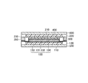
図1は、本発明の第一実施形態に係る表示装置を模式的に示す平面図である。また、図2は、図1の切断線II‐IIにおける断面を示す図であり、第一実施形態に係る表示装置の構成を示す図である。図3は、図2の破線IIIによって囲まれる領域を拡大して示す図である。 FIG. 1 is a plan view schematically showing a display device according to the first embodiment of the present invention. FIG. 2 is a diagram showing a cross section taken along the section line II-II in FIG. 1, and is a diagram showing a configuration of the display device according to the first embodiment. FIG. 3 is an enlarged view showing a region surrounded by a broken line III in FIG.
本発明の第一実施形態に係る表示装置10は、自発光素子層132等を含んで構成される機能層を備える第一基板100と、対向基板である第二基板200とを有するものである。
The
はじめに、第一基板100の構成について説明する。第一基板100は、フレキシブルな樹脂で形成された第一樹脂層110と、第一樹脂層110上に形成された第一機能層130とを含んで構成されている。
First, the configuration of the
第一樹脂層110は、柔軟性に優れ可撓性を有する材料によって形成され、例えば、ポリイミド、ポリエチレンテレフタレート(PET)によって形成されることとしてもよい。
The
また、第一樹脂層110の下面側(後述する薄膜トランジスタ(TFT)層131と対向する側とは反対側)には、外部からの水分を遮断する第一保護フィルム140が取りつけられていることとしてもよい。第一保護フィルム140は、例えば、ポリエチレンフィルム、アルミフィルム等で実現されることとしてもよい。
In addition, a first
また、図2に示されるように、第一樹脂層110の側面部には、第一樹脂層110の上面(後述するTFT層131と対向する側の面)に載る部分を有するように設けられた第一枠体120が備えられている。また、図1に示されるように、第一枠体120は第一樹脂層110の周囲に備えられる。
Further, as shown in FIG. 2, the side surface portion of the
また、第一枠体120を第一樹脂層110の上面に載るように設けるために、第一枠体120の厚さは、第一樹脂層110の厚さよりも大きいものとすることとしてもよい。
Further, in order to provide the
なお、後に詳しく説明するが、表示装置10に備えられる第一枠体120は、その製造方法において第一樹脂層110の周囲に埋め込まれるように形成されるものである。したがって、第一枠体120を後の説明においては、以後、第一埋め込み層120と呼ぶこととする。
As will be described in detail later, the
図3に示されるように、第一埋め込み層120は、第一樹脂層110の周囲に埋め込まれるように形成されることによって、第一樹脂層110の上面に載る部分を有するように設けられることとなる。
As shown in FIG. 3, the first embedded
また、第一埋め込み層120を形成する材料の防湿性は、第一樹脂層110を形成する材料よりも防湿性が高いものである。すなわち、第一埋め込み層120の防湿性は、第一樹脂層110の防湿性よりも高いものである。
Further, the moisture resistance of the material forming the first buried
また、第一埋め込み層120は無機材料によって形成されることとしてもよい。第一樹脂層110は、前述のようにポリイミド等の有機樹脂によって形成される。有機樹脂は、無機材料と比較して水との親和性が高いため、外部の水蒸気等に起因する水分を取り込みやすいため防湿性が低いものである。
The first embedded
仮に第一樹脂層110を経由して外部の水分が表示装置10の内部に侵入した場合、自発光素子層132等に悪影響を及ぼし、表示不良等を引き起こす虞がある。
If external moisture enters the inside of the
表示装置10に備えられる第一埋め込み層120は、外部からの水分が表示装置10内部に侵入することを抑制するために、第一樹脂層110の外表面を覆うように形成される。そして第一埋め込み層120が、第一樹脂層110の上面の一部まで覆うように備えられることによって、表示装置10内部への水分の侵入を更に抑制することとなる。
The first embedded
第一機能層130は、図2に示されるようにTFT層131と、TFT層131の第一樹脂層110と対向する側とは反対側に形成された自発光素子層132と、TFT層131と第一樹脂層110との間に備えられる第一バリア層133と、自発光素子層132のTFT層131と対向する側とは反対側に形成された第二バリア層134と、を含むこととしてもよい。
As shown in FIG. 2, the first
そして、図2に示されるように第二バリア層134は、TFT層131の側面と、自発光素子層132の端面とを取り囲むように配置されることとしてもよい。 第一機能層130の一部を構成する第一バリア層133及び第二バリア層134は、第一機能層130の内部を、外部からの腐食性ガス、水分、金属イオン等の汚染から保護するものである。
As shown in FIG. 2, the
第一バリア層133及び第二バリア層134は、例えば、Al2O3、SiO2等の金属酸化物、SiN等の金属窒化物等によって形成されることとしてもよい。また、第一バリア層133及び第二バリア層134は、例えばCVD(chemical vapor deposition)法、PVD法(physical vapor deposition)、ALD(atomic layer deposition)法を用いて形成されることとしてもよい。
The
また、第一機能層130の一部を構成するTFT層131は、第一樹脂層110上に薄膜トランジスタ(TFT)を有する画素がマトリクス状に配置されたものである。
The
TFT層131の一部を構成する、TFTは、ポリシリコンなどの半導体膜と、半導体膜を覆うゲート絶縁膜と、ゲート絶縁膜を介して半導体膜の上方に配置されたゲート電極と、ゲート絶縁膜を貫通して半導体膜に電気的に接続するソース電極及びドレイン電極と、を含むこととしてもよい。また、TFT層131を構成する複数のTFTを制御するための、制御回路(図示なし)が、例えば前述の第一樹脂層110上に配置されることとしてもよい。
The TFT constituting a part of the
また、第一機能層130の一部を構成する自発光素子層132は、画像を構成する複数の単位画素それぞれで輝度が制御されて発光するように設けらる。自発光素子層132は、共通電極132Bと、共通電極132BとTFT層131との間にある複数の画素電極132Aと、共通電極132Bと複数の画素電極132Aとの間に介在する発光層132Cと、を含むものである。
In addition, the self-
共通電極132Bは、ITO(Indium Tin Oxide、インジウムスズ酸化物)やIZO(Indium Zinc Oxide、インジウム亜鉛酸化物)等の透明金属による導電膜で形成されることとしてもよい。
The
また本明細書中における発光層132Cは、有機発光層であることとしてもよいし、QLED(Quantum-dot Light Emitting Diode)等に代表される無機発光層であることとしてもよい。、また、有機発光層は、電子輸送層、ホール輸送層、電子注入層、ホール注入層等を含むこととしてもよい。
In addition, the
第一実施形態に係る表示装置10における発光層132Cは、単色(白色)の光を発する材料で、複数の画素電極132Aに対して連続的に設けられている。他の態様として、発光層132Cは、それぞれの画素電極132Aに対して、複数色(例えば、R(赤色)、G(緑色)、B(青色)の3色)の発光部に分割されて設けられることとしてもよい。
The
次に、第二基板200の構成について説明する。第二基板200は、フレキシブルな樹脂で形成された第二樹脂層210と、第二樹脂層210上に形成された第二機能層230とを含んで構成されている。
Next, the configuration of the
第二樹脂層210は、柔軟性に優れ可撓性を有する材料によって形成され、例えば、ポリイミド、ポリエチレンテレフタレート(PET)によって形成されることとしてもよい。
The
また、第二樹脂層210の上面側(後述するカラーフィルタ層231と対向する側とは反対側)には、外部からの物理的な損傷等を抑制する第二保護フィルム(図示なし)が取りつけられていることとしてもよい。第二保護フィルムは、例えば、ポリエチレンフィルム等で実現されることとしてもよい。
A second protective film (not shown) that suppresses physical damage from the outside is attached to the upper surface side of the second resin layer 210 (the side opposite to the side facing the
また、第二樹脂層210の側面部には、第二樹脂層210の周囲を囲むように設けられた第二枠体220が備えられていることとしてもよい。また、第二枠体220は、平面視において第一枠体120と後述するシール材300と少なくとも一部が重なるように配置されることとしてもよい。
The
なお、後に詳しく説明するが、第二樹脂層210の周囲を囲むように設けられる第二枠体220は、その製造方法において第二樹脂層210の周囲に埋め込まれるように形成されるものである。したがって、第二枠体220を後の説明においては、以後、第二埋め込み層220と呼ぶこととする。
As will be described in detail later, the
また、第二埋め込み層220を形成する材料の防湿性は、第二樹脂層210を形成する材料よりも防湿性が高いものであることとしてもよい。
Moreover, the moisture resistance of the material forming the second embedded
また、第二埋め込み層220は無機材料によって形成されることとしてもよい。第二樹脂層210は、前述のようにポリイミド等の有機樹脂によって形成される。仮に第二樹脂層210を経由して外部の水分が第二基板200の内部に侵入した場合、第二基板200内部に曇りが発生する等の理由により表示不良等を引き起こす虞がある。
The second embedded
表示装置10に備えられる第二埋め込み層220は、外部からの水分が表示装置10内部に侵入することを抑制するために、第二樹脂層210の側端面を覆うように形成されるものである。
The second embedded
第二機能層230は、図2に示されるように、カラーフィルタ層231と、カラーフィルタ層231の第二樹脂層210と対向する側とは反対側に形成された第三バリア層232と、を含むこととしてもよい。
As shown in FIG. 2, the second
第二機能層230の一部を構成するカラーフィルタ層231は、図2に示されるようにR(赤色)、G(緑色)、B(青色)の着色層231R,231G,231Bを含んで構成されていることとしてもよい。前述の自発光素子層132から発せられる光が単色(白色)である場合、自発光素子層132から発せられる光(白色)は、各色の着色層231R,231G,231Bを通過することによって、R(赤色)、G(緑色)、B(青色)それぞれの色として外部にて視認されることとなる。
The
カラーフィルタ層231に含まれる着色層231R,231G,231Bのそれぞれは、樹脂内にR(赤色)、G(緑色)、B(青色)それぞれの色の顔料を内部に分散したものであることとしてもよい。
Each of the
また、カラーフィルタ層231は、それぞれの色の領域を通過した光が隣接する他の色の領域に入り込むことを防ぐために、各色の着色層231R,231G,231Bの間にブラックマトリクス231Kを備えることとしてもよい。また、ブラックマトリクス231Kは、樹脂内に黒色の顔料を内部に分散したものであることとしてもよい。
In addition, the
なお、第一機能層130の一部を構成する発光層132Cが、複数色(例えば、R(赤色)、G(緑色)、B(青色)の3色)の発光部に分割されて設けられる、所謂塗り分け方式の発光層132Cである場合、第二機能層230はカラーフィルタ層231を含まないこととしてもよい。
The
第二機能層230の一部を構成する第三バリア層232は、第二機能層230の内部を、外部からの腐食性ガス、水分、金属イオン等の汚染から保護するものである。第三バリア層232は、例えば、Al2O3、SiO2等の金属酸化物、SiN等の金属窒化物等によって形成されることとしてもよい。また、第三バリア層232は、例えばCVD法、PVD法、ALD法を用いて形成されることとしてもよい。
The
第一実施形態に係る表示装置10は、上記説明した第一基板100と、対向基板である第二基板200とは、シール材300(ダム材ともいう)及び/又は充填材400(フィル材ともいう)を介して互いに貼り合わせがされていることとしてもよい。
In the
図2に示されるように、第一実施形態に係る表示装置10は、第一基板100の一部を構成する第二バリア層134と、第二基板200とが、充填材400と、平面視において充填材400の周囲を取り囲むように配置されたシール材300と、を介して互いに貼り合わせがされている。
As shown in FIG. 2, in the
また、図2に示されるように、上述のように第一基板100と第二基板200とが貼り合わせされることによって、第一バリア層133と第二バリア層134とは、シール材300と第一埋め込み層120とに挟持されることとなる。
Further, as shown in FIG. 2, the
充填材400は、例えば光硬化樹脂等であることとしてもよい。充填材400が光硬化樹脂によって形成される場合、充填材400が配置される領域の周縁にシール材300を設け、シール材300によって囲まれる領域に、硬化前の光硬化樹脂を流し込み、その後光硬化することによって、第一基板100と第二基板200の貼り合せが行われることとしてもよい。
The
また、第一基板100と、対向基板である第二基板200との間には、両基板の間隔を均一なものとするために、スペーサ350が備えられることとしてもよい。スペーサ350は、シール材300の外側領域のみに備えられることとしてもよい。また、スペーサ350は、第一基板100の端部と第二基板200の端部の間を埋めるように備えられることとしてもよい。
In addition, a
図2に示されるように、第一実施形態に係る表示装置10には、シール材300の充填材400と対向する側とは反対側であって、第二バリア層134と第二基板200との間に配置されるスペーサ350が備えられている。
As shown in FIG. 2, the
[第二実施形態に係る表示装置]
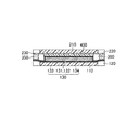
以下に、本発明の第二実施形態に係る表示装置20について、図4を参照して説明する。図4は、第二実施形態に係る表示装置の構成を示す断面図である。
[Display Device According to Second Embodiment]
Below, the
第二実施形態に係る表示装置20は、第一埋め込み層120の形状が、第一実施形態に係る表示装置10に備えられる第一埋め込み層120の形状と異なるものである。第二実施形態に係る表示装置20のそれ以外の構成については、第一実施形態に係る表示装置10と同様である。
In the
第二実施形態に係る表示装置20の一部を構成する第一埋め込み層120は、平面視において第一樹脂層110の周囲に備えられるとともに、第一樹脂層110の上面(TFT層131と対向する側の面)の全体を覆うように備えられている。
The first embedded
第二実施形態に係る表示装置20の第一埋め込み層120が、第一樹脂層110の周囲と上面の全面を覆うように備えられることによって、第一実施形態に係る表示装置10と比較して、表示装置20内部への水分の侵入を更に抑制することとなる。
Compared with the
[第一実施形態に係る表示装置の製造方法]
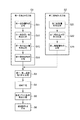
次に、第一実施形態に係る表示装置の製造方法について説明する。図5は、第一実施形態に係る表示装置の製造方法を説明するフローチャートである。
[Method for Manufacturing Display Device According to First Embodiment]
Next, a method for manufacturing the display device according to the first embodiment will be described. FIG. 5 is a flowchart illustrating a method for manufacturing the display device according to the first embodiment.
図5に示されるように、第一実施形態に係る表示装置10の製造方法は、第一基板形成工程S1と、第二基板形成工程S2と、を含むこととしてもよい。
As FIG. 5 shows, the manufacturing method of the
第一基板形成工程S1は、複数の第一領域及びそれぞれの第一領域を囲む形状の第二領域を有する第一基体500を用意し、第二領域を避けて複数の第一領域に第一樹脂層110を形成する工程(第一樹脂層形成工程S11、及び、第一樹脂層一部除去工程S12)と、第二領域に、第一樹脂層110よりも防湿性の高い第一埋め込み層120を形成する工程(第一埋め込み層形成工程S13)と、第一樹脂層110及び第一埋め込み層120の上に、画像を構成する複数の単位画素それぞれで輝度が制御されて発光する自発光素子層132を含む第一機能層130を形成する工程(第一機能層形成工程S14)と、を含むものである。
The first substrate forming step S1 prepares a
そして、第一実施形態に係る表示装置10の製造方法は、第一樹脂層110を複数の第一領域にそれぞれ対応して複数の部分に分離するように、第二領域を通るラインで、第一埋め込み層120及び第一機能層130を切断する工程(切断工程S4)を含むものである。
And the manufacturing method of the
なお、後に詳細に説明する切断工程S4において、第二領域を通るラインで、第一埋め込み層120及び第一機能層130を切断する切断線を、図6A〜6Kにおいて符号SLと示すこととする。
In addition, in cutting process S4 demonstrated in detail later, the cutting line which cut | disconnects the
また、第二基板形成工程S2は、第二基体600を用意し、第二基体600上に第二樹脂層210を形成する工程(第二樹脂層形成工程S21)と、第二樹脂層210よりも防湿性の高い第二埋め込み層220を形成する工程(第二埋め込み層形成工程S22)と、第二樹脂層210及び第二埋め込み層220の上に、カラーフィルタ層231を含む第二機能層230を形成する工程(第二機能層形成工程S23)と、を含むこととしてもよい。
In the second substrate forming step S <b> 2, the
以下、第一実施形態に係る表示装置10の製造方法におけるそれぞれの工程について図6A〜6Kを参照して説明する。
Hereinafter, each process in the manufacturing method of the
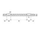
図6Aは、第一実施形態に係る表示装置の製造方法を説明する図であり、第一基体に第一樹脂層を積層した状態を示す図である。 FIG. 6A is a diagram for explaining the manufacturing method of the display device according to the first embodiment, and shows a state in which the first resin layer is laminated on the first base.
第一実施形態に係る表示装置の製造に際し、はじめに用意された第一基体500に、フレキシブルな第一樹脂層110を形成する(第一樹脂層形成工程S11)。第一樹脂層形成工程S11は、複数の第1領域及びそれぞれの第一領域を囲む形状の第二領域を有する第一基体500を用意し、複数の第一領域及び第二領域に第一樹脂層110を形成する工程である。
In manufacturing the display device according to the first embodiment, the flexible
第一基体500が有する第一領域A1とは、後の工程において第一機能層130の一部を構成する自発光素子層132が形成される領域を含むものである。また、第二領域A2とは、自発光素子層132が形成される領域の周囲を取り囲み、後の切断工程S4において切断する切断線SLを該領域内に含むものである。
The first region A1 included in the
用意される第一基体500は、無機材料によって形成されたものであることとしてもよい。具体的には、第一基体500は、ガラス等によって形成されたものであることとしてもよい。
The prepared
また、第一樹脂層110は例えば所定の樹脂を溶剤等に溶かした樹脂ワニスを第一基体500上に塗布し、溶剤を揮発させることによって形成することとしてもよい。
The
後の工程において、第一基体500は形成された第一樹脂層110と剥離されることとなる。したがって、第一基体500は、第一樹脂層110との剥離の容易さ等を考慮した材料によって形成されることが好ましく、例えばガラス等の無機材料で形成されることとしてもよい。
In the subsequent process, the
ガラス等の無機材料で形成された第一基体500は、有機材料によって形成される第一樹脂層110との親和性が弱いため、後の工程において容易に剥離可能となる。
Since the
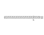
図6Bは、第一実施形態に係る表示装置の製造方法を説明する図であり、第一樹脂層の一部を除去した状態を示す図である。 FIG. 6B is a diagram for explaining the manufacturing method of the display device according to the first embodiment, and shows a state in which a part of the first resin layer is removed.
第一樹脂層一部除去工程S12においては、第一樹脂層形成工程S11にて形成された第一樹脂層110のうち、第二領域A2に形成された第一樹脂層110の一部を除去する。すなわち、第一基体500上には、複数の第一領域A1に形成された第一樹脂層110のみが残ることとなる。
In the first resin layer partial removal step S12, a part of the
第一樹脂層一部除去工程S12における第一樹脂層110の一部除去は、例えば所定のマスクを用いてパターニングすることによって実現されることとしてもよい。
The partial removal of the
また、第一樹脂層一部除去工程S12における第一樹脂層110の一部除去は、例えばレーザー光線を用いた加工技術であるレーザーアブレーションを適用し実現することとしてもよい。レーザーアブレーションによる第一樹脂層110の一部除去は、マスクレスにて行うことが可能となるため、運用費の削減や、専用設備の導入の必要がなく、製造コストの低減が期待できる。
Further, the partial removal of the
図6Cは、第一実施形態に係る表示装置の製造方法を説明する図であり、第一埋め込み層を形成した状態を示す図である。 FIG. 6C is a diagram for explaining the manufacturing method of the display device according to the first embodiment, and shows a state in which the first buried layer is formed.
第一樹脂層一部除去工程S12によって第一樹脂層110の一部が除去されることによって、第一基体500上には凹部110CPが形成されていることとなる。第一埋め込み層形成工程S13においては、該凹部110CPを埋めるように第一埋め込み層120を形成する。
By removing a part of the
第一埋め込み層120を形成する材料の防湿性は、第一樹脂層110を形成する材料の防湿性よりも高いものである。例えば、第一埋め込み層120が防湿性に優れた無機材料によって形成される場合、第一埋め込み層120はCVD法、PVD法、ALD法を用いて形成されることとしてもよい。
The moisture resistance of the material forming the first buried
このように、第一樹脂層110に予め形成された凹部を埋めるように、第一埋め込み層120を形成することによって、第一樹脂層110の上面に載る部分を有するように第一埋め込み層120を容易に形成することができる。
As described above, the first embedded
図6Dは、第一実施形態に係る表示装置の製造方法を説明する図であり、自発光素子層を含む第一機能層を形成した状態を示す図である。 FIG. 6D is a diagram for explaining the manufacturing method of the display device according to the first embodiment, and is a diagram showing a state in which the first functional layer including the self-light emitting element layer is formed.
第一機能層形成工程S14においては、表示装置10の表示機能を発揮するための第一機能層130を形成する。具体的には、本実施形態に係る表示装置10の第一機能層130は、TFT層131、自発光素子層132を含んで構成されている。
In 1st functional layer formation process S14, the 1st
TFT層131、自発光素子層132は、既知の半導体製造プロセス方法である写真蝕刻技術(PEP技術、フォトリソグラフィ技術等)を用いて形成されることとしてもよい。
The
以上、図6A〜6Dを参照して説明した工程を経て、第一基板形成工程S1が完了する。 As described above, the first substrate forming step S1 is completed through the steps described with reference to FIGS.
次に、図6E〜6Gを参照して第二基板形成工程S2について説明する。第二基板形成工程S2は、先に説明した第一基板形成工程S1とは別工程で行われることとなる。 Next, the second substrate forming step S2 will be described with reference to FIGS. The second substrate forming step S2 is performed in a step different from the first substrate forming step S1 described above.
図6Eは、第一実施形態に係る表示装置の製造方法を説明する図であり、第二基体に第二樹脂層を積層した状態を示す図である。 FIG. 6E is a view for explaining the method for manufacturing the display device according to the first embodiment, and shows a state in which the second resin layer is laminated on the second base.
第二基板形成工程S2においては、はじめに用意された第二基体600に、フレキシブルな第二樹脂層210を形成する(第二樹脂層形成工程S21)。第二樹脂層形成工程S21においては、第二基体600の一方側の面の全てを覆うように第二樹脂層210を形成することとしてもよい。
In the second substrate forming step S2, a flexible
また、用意される第二基体600は、無機材料によって形成されたものであることとしてもよい。具体的には、第二基体600は、ガラス等によって形成されたものであることとしてもよい。
The prepared
また、第二樹脂層210は例えば所定の樹脂を溶剤等に溶かした樹脂ワニスを第二基体600上に塗布し、溶剤を揮発させることによって形成することとしてもよい。
The
後の工程において、第二基体600は形成された第二樹脂層210と剥離されることとなる。したがって、第二基体600は、第二樹脂層210との剥離の容易さ等を考慮した材料によって形成されることが好ましく、例えばガラス等の無機材料で形成されることとしてもよい。
In the subsequent process, the
ガラス等の無機材料で形成された第二基板200は、有機材料によって形成される第二樹脂層210との親和性が弱いため、後の工程において容易に剥離可能となる。
Since the
図6Fは、第一実施形態に係る表示装置の製造方法を説明する図であり、第二樹脂層の一部を除去した後、第二埋め込み層を形成した状態を示す図である。 FIG. 6F is a view for explaining the manufacturing method of the display device according to the first embodiment, and shows a state in which the second embedded layer is formed after removing a part of the second resin layer.
第二埋め込み層220は、形成された第二樹脂層210の一部を除去することによって形成された凹部210CPに所定の材料を埋め込むことによって形成される。該凹部210CPは、例えば、所定のマスクを用いてパターニングする方法や、レーザー光線を用いた加工技術であるレーザーアブレーションを適用した方法によって形成されることとしてもよい。
The second embedded
また、第二埋め込み層220を形成する材料の防湿性は、第二樹脂層210を形成する材料の防湿性よりも高いものであることとしてもよい。第二埋め込み層220が無機材料によって形成される場合、例えばCVD法、PVD法,ALD法を用いて形成されることとしてもよい。
The moisture resistance of the material forming the second embedded
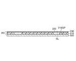
図6Gは、第一実施形態に係る表示装置の製造方法を説明する図であり、カラーフィルタ層を含む第二機能層を形成した状態を示す図である。 FIG. 6G is a diagram for explaining the manufacturing method of the display device according to the first embodiment, and is a diagram showing a state in which the second functional layer including the color filter layer is formed.
カラーフィルタ層231は、既知の方法である写真蝕刻技術(PEP技術、フォトリソグラフィ技術等)を用いて形成されることとしてもよい。
The
以上、図6E〜6Gを参照して説明した工程を経て、第二基板形成工程S2が完了する。 As described above, the second substrate formation step S2 is completed through the steps described with reference to FIGS.
次に、図6Dに示される第一基板100と、図6Gに示される第二基板200とを貼り合せる(第一、第二基板貼り合せ工程S3)。図6Hは、第一実施形態に係る表示装置の製造方法を説明する図であり、図6Dに示される第一基板と、図6Gに示される第二基板とを貼り合せた状態を示す図である。
Next, the
両基板(第一、第二基板100,200)の貼り合せは、両基板に形成された第一埋め込み層120、第二埋め込み層220の周辺に備えられたシール材300を介して行われることとしてもよい。そして、第一基板100および、第二基板200の間には、間隙を埋めるように充填材400が充填されることとしてもよい。
The two substrates (first and
また、本工程において、第一基板100と第二基板200との間隔が一定なものとなるように、後に行われる切断工程S4にて切断される位置、すなわち第一埋め込み層120及び第一機能層130を切断する切断線SL上にスペーサ350を設けることとしてもよい。
In this step, the positions to be cut in the subsequent cutting step S4, that is, the first buried
また、図6Dに参照されるように、対向基板である第二基板200に備えられた第二埋め込み層220が、第二領域A2に対応する位置にあるように、第二基板200が、第一基板100に貼り合わされることとしてもよい。
In addition, as illustrated in FIG. 6D, the
このように貼り合せることによって、切断工程S4において切断されるライン上に、第一埋め込み層120、第二埋め込み層220のそれぞれが配置されることとなる。ここで、第一埋め込み層120及び/又は第二埋め込み層220が無機材料で形成されている場合、一般的に無機材料は有機材料よりも脆く割れやすい性質を有するため、後の切断工程S4において切断が容易に行えるという利点を有する。
By bonding in this way, each of the
次に、第一、第二基板貼り合せ工程S3にて貼り合わされたものを、表示装置10に相当する単位ごとに切断する(切断工程S4)。図6Iは、第一実施形態に係る表示装置の製造方法を説明する図であり、多面取りパネルを表示装置に相当する単位ごとに切断した状態を示す図である。 Next, what was bonded in 1st, 2nd board | substrate bonding process S3 is cut | disconnected for every unit equivalent to the display apparatus 10 (cutting process S4). FIG. 6I is a diagram for explaining the method for manufacturing the display device according to the first embodiment, and shows a state in which the multi-panel is cut into units corresponding to the display device.
切断工程S4は、例えば、第一、第二基体500,600をスクライブ(例えば、金属等の針を用いて刻みをつける、あるいはレーザー光線をして刻みをつける)し、ブレイク(スクライブした刻みに沿って分断)することによって行われることとしてもよい。すなわち、切断工程S4においては、第一埋め込み層120、第一機能層130とともに、第一基体500を切断することとしてもよい。また、切断工程S4においては、第一埋め込み層120、第一機能層130とともに、第二基板200を切断することとしてもよい。
In the cutting step S4, for example, the first and
次いで、表示装置10に相当する単位ごとに切断した状態のものから、切断された第一、第二基体500,600のそれぞれを剥離する(基体(ガラス基板)除去工程S5)。
Next, each of the cut first and
図6Jは、第一実施形態に係る表示装置の製造方法を説明する図であり、第一、第二基体を剥離した状態を示す図である。 FIG. 6J is a diagram for explaining the method for manufacturing the display device according to the first embodiment, and shows a state where the first and second substrates are peeled off.
先に説明したように、ガラス等の無機材料で形成された第一、第二基体500,600は、有機材料によって形成される第一、第二樹脂層110,210との親和性が弱いため、本工程において容易に剥離可能となる。
As described above, the first and
最後に、第一基体500が剥離され露出した第一樹脂層110の面に、外部からの水分の侵入、あるいは外部からの物理的損傷を防止するための第一保護フィルム140を取りつける(保護膜形成工程S6)。
Finally, a first
なお、保護膜形成工程S6においては、第二基体600が剥離され露出した第二樹脂層210の面に、物理的損傷を防止するための第二保護フィルム(図示なし)を取りつけることとしてもよい。
In the protective film forming step S6, a second protective film (not shown) for preventing physical damage may be attached to the surface of the
図6Kは、第一実施形態に係る表示装置の製造方法を説明する図であり、保護フィルムを取りつけ第一実施形態に係る表示装置が完成した状態を示す図である。図6Kに示されるように、第一保護フィルム140は第一樹脂層110の第一機能層130が配置される側とは反対側に配置されることとなる。
FIG. 6K is a diagram for explaining the manufacturing method of the display device according to the first embodiment, and shows a state where the protective film is attached and the display device according to the first embodiment is completed. As shown in FIG. 6K, the first
以上の工程を経て、第一実施形態に係る表示装置10を得ることができる。
Through the above steps, the
上記製造工程を経て得られる表示装置10は、樹脂層と、前記樹脂層の周囲に、前記樹脂層の上面に載る部分を有するように設けられた枠体と、前記樹脂層の上面及び前記枠体の上面に積層され、画像を構成する複数の単位画素それぞれで輝度が制御されて発光する自発光素子層132と、を含む、ことを特徴とする表示装置10である。
The
そして、上記製造工程を経て得られる表示装置10は、水分バリア性を高め、これによって信頼性が向上された表示装置10である。
And the
[第三実施形態に係る表示装置]
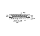
以下に、本発明の第三実施形態に係る表示装置30について、図7を参照して説明する。図7は、第三実施形態に係る表示装置の構成を示す断面図である。
[Display Device According to Third Embodiment]
Below, the
第三実施形態に係る表示装置30は、第一埋め込み層120の形状が、第一実施形態に係る表示装置10に備えられる第一埋め込み層120の形状と異なるものである。第三実施形態に係る表示装置30のそれ以外の構成については、第一実施形態に係る表示装置10と同様である。
In the
第三実施形態に係る表示装置30の一部を構成する第一埋め込み層120は二つの部分にて構成されるものである。より具体的には、第一埋め込み層120のうち、第一樹脂層の上面に載る部分は、CVD、PVD、ALD等によって形成された第一無機絶縁膜120Aによって形成されたものである。
The first embedded
第一無機絶縁膜120AはAlO、SiO、SiN、SiC、SiCN、SiON、SiOCN等の材料によって形成された膜であることとしてもよい。該材料がCVD、PVD、ALD等によって形成されることにより、第一無機絶縁膜120Aはより緻密な膜として形成されることとなる。
The first inorganic insulating
高密度の第一無機絶縁膜120Aは、水分、ガスを遮断する性能が高く、その結果、表示装置30の信頼性を更に高めることとなる。一方で、第一無機絶縁膜120Aはプロセス上、膜厚の大きい被膜を形成することが困難である。
The high-density first inorganic insulating
そのため、第三実施形態に係る表示装置30は、第一無機絶縁膜120Aの他に、SOG(Spin on Glass)、PSG(Phosphorus Silicon Glass)、BPSG(Boron Phosphorus Silicon Glass)等によって形成される第二無機絶縁膜120Bを含むものである。
Therefore, the
SOG、PSG、BPSG等によって形成される第二無機絶縁膜120Bは第一無機絶縁膜120Aと比較して低密度である反面、材料の特性上、膜厚の大きい被膜を形成することが可能であり、埋め込み特性が優れるものである。
The second inorganic insulating
このように、第一埋め込み層120が、密度の異なる二つの無機絶縁膜により構成されることにより、第一埋め込み層120の厚さが、第一樹脂層110の厚さよりも大きいものとなる。これによって、シール材300が凹部110CPに入り込むことに起因するシール性の低下や、あるいはスペーサ350が凹部110CPに入り込んで両基板の間隔を不均一なものとすることを抑制することとなる。
As described above, since the first embedded
また、切断線SL上に、無機材料によって形成される第三実施形態に係る表示装置30の第一埋め込み層120が備えられることにより、製造プロセスにおいて切断が容易に行えるという利点も有することとなる。
In addition, since the first embedded
[第四実施形態に係る表示装置]
以下に、本発明の第四実施形態に係る表示装置40について、図8を参照して説明する。図8は、第四実施形態に係る表示装置の構成を示す断面図である。
[Display Device According to Fourth Embodiment]
Below, the
第四実施形態に係る表示装置40は、第一埋め込み層120の形状が、第一実施形態に係る表示装置10に備えられる第一埋め込み層120の形状と異なるものである。第四実施形態に係る表示装置40のそれ以外の構成については、第一実施形態に係る表示装置10と同様である。
In the
第四実施形態に係る表示装置40の一部を構成する第一埋め込み層120は、平面視において第一樹脂層110の周囲に備えられるとともに、第一樹脂層110の上面(TFT層131と対向する側の面)の全体を覆うように備えられている。
The first embedded
また、第四実施形態に係る表示装置40の一部を構成する第一埋め込み層120は、第三実施形態に係る表示装置30の一部を構成する第一埋め込み層120と同様、二つの部分にて構成されるものである。
Moreover, the
そして、第一樹脂層110の上面の全体を覆う部分は、CVD、PVD、ALD等によって形成された第一無機絶縁膜120Aによって形成されたものである。また、第四実施形態に係る表示装置40は、第一無機絶縁膜120Aの他に、SOG、PSG、BPSG等によって形成される第二無機絶縁膜120Bを含むものである。
A portion covering the entire upper surface of the
このように、第一無機絶縁膜120Aが第一樹脂層110の上面の全体を覆うことによって、表示装置40の信頼性を更に高めることとなる。
As described above, the first inorganic insulating
なお図8に示される第四実施形態に係る表示装置40では、第一機能層130の一部を構成する第一バリア層133が設けられているが、第一無機絶縁膜120Aが備えられることにより、第一バリア層133は省略することとしてもよい。
In the
[第三実施形態に係る表示装置の製造方法]
次に、第三実施形態に係る表示装置の製造方法について説明する。なお、第三実施形態に係る表示装置30の製造は、第一実施形態に係る表示装置10の製造と同様、図5に示されるフローにそって行われる。
[Method for Manufacturing Display Device According to Third Embodiment]
Next, a method for manufacturing a display device according to the third embodiment will be described. In addition, manufacture of the
以下、第三実施形態に係る表示装置30の製造方法におけるそれぞれの工程について図9A〜9Kを参照して説明する。
Hereinafter, each process in the manufacturing method of the
図9Aは、第三実施形態に係る表示装置の製造方法を説明する図であり、第一基体に第一樹脂層を積層した状態を示す図である。 FIG. 9A is a view for explaining the method for manufacturing the display device according to the third embodiment, and shows a state in which the first resin layer is laminated on the first base.
第三実施形態に係る表示装置の製造に際し、はじめに用意された第一基体500に、フレキシブルな第一樹脂層110を形成する(第一樹脂層形成工程S11)。第一樹脂層形成工程S11は、複数の第1領域及びそれぞれの第一領域を囲む形状の第二領域を有する第一基体500を用意し、複数の第一領域及び第二領域に第一樹脂層110を形成する工程である。
In manufacturing the display device according to the third embodiment, the flexible
第三実施形態に係る表示装置30の製造においては、第一基体500上の第一樹脂層110が形成される面に、犠牲剥がれ層700が予め形成されている。犠牲剥がれ層700は、α−カーボン、α−Si、金属薄膜等によって形成されることとしてもよい。
In the manufacture of the
ここで、先に説明した第一実施形態に係る表示装置10の製造と同様に、第三実施形態に係る表示装置30の製造においても、後に第一基体500を除去する工程(基体(ガラス基板)除去工程S5)が行われることとなる。
Here, similarly to the manufacture of the
例えば上記例示した材料によって形成された犠牲剥がれ層700と第一樹脂層110との剥離は、第一基体500と第一樹脂層110との剥離と比べ容易なものとなる。これによって、第一基体500を除去する工程(基体(ガラス基板)除去工程S5)をより容易に実施することができる。
For example, the peeling between the
なお、犠牲剥がれ層700は先に説明した第一実施形態に係る表示装置10の製造においても用いることができる。
The
第三実施形態に係る表示装置30の製造において用意される第一基体500や、第一樹脂層110は、第一実施形態に係る表示装置10の製造に用いたものと同様のものを用いることができる。また、第一樹脂層110は、第一実施形態に係る表示装置10の製造にて説明した方法と同様の方法にて形成することができる。
The
図9Bは、第三実施形態に係る表示装置の製造方法を説明する図であり、第一樹脂層の一部を除去した状態を示す図である。 FIG. 9B is a diagram illustrating the method for manufacturing the display device according to the third embodiment, and is a diagram illustrating a state in which a part of the first resin layer is removed.
第一樹脂層一部除去工程S12においては、第一樹脂層形成工程S11にて形成された第一樹脂層110のうち、第二領域A2に形成された第一樹脂層110の一部を除去する。すなわち、第一基体500上には、複数の第一領域A1に形成された第一樹脂層110のみが残ることとなる。
In the first resin layer partial removal step S12, a part of the
第三実施形態に係る表示装置の製造における、第一樹脂層110の一部除去は、第一実施形態に係る表示装置10の製造にて説明した方法と同様の方法にて行うこととしてもよい。
The partial removal of the
図9Cは、第三実施形態に係る表示装置の製造方法を説明する図であり、第一埋め込み層を形成した状態を示す図である。第三実施形態に係る表示装置30は、第一埋め込み層120の形状が、第一実施形態に係る表示装置10に備えられる第一埋め込み層120の形状と異なり、二つの部分にて構成されるものである。
FIG. 9C is a view for explaining the manufacturing method of the display device according to the third embodiment, and shows a state in which the first buried layer is formed. The
第一樹脂層一部除去工程S12にて第一樹脂層110の一部が除去されることによって、第一基体500上には凹部110CPが形成されていることとなる。第一埋め込み層形成工程S13においては、該凹部110CPを埋めるように第一埋め込み層120を形成する。
By removing a part of the
第一埋め込み層120の形成は、はじめに、第一樹脂層110の上面に載る部分となる、第一無機絶縁膜120AをAlO、SiO、SiN、SiC、SiCN、SiON、SiOCN等の材料を用い、CVD、PVD、ALD等によって形成する。
For the formation of the first buried
第一無機絶縁膜120Aは、第一樹脂層110の全面に一旦形成した後、凹部110CPに相当する場所のみを残して、他の部分を取り除くことによって形成することとしてもよいし、マスク等を用いて、凹部110CPに相当する場所にのみ形成することとしてもよい。
The first inorganic insulating
第一無機絶縁膜120Aは、膜厚の大きい被膜を形成することが困難であるため、第一樹脂層110の一部を除去したことによって形成された凹部110CPを完全に埋めることは困難である。
Since the first inorganic insulating
そこで、第二無機絶縁膜120Bを第一無機絶縁膜120A上に、SOG(Spin on Glass)、PSG(Phosphorus Silicon Glass)、BPSG(Boron Phosphorus Silicon Glass)等によって凹部110CPを完全に埋めるように形成する。
Therefore, the second inorganic insulating
なお、第一無機絶縁膜120Aを第一樹脂層110の全面に一旦形成した後、凹部110CPに相当する場所のみに第二無機絶縁膜120Bを形成することによって、第四実施形態に係る表示装置40を製造することができる。
The first inorganic insulating
図9Dは、第三実施形態に係る表示装置の製造方法を説明する図であり、自発光素子層を含む第一機能層を形成した状態を示す図である。 FIG. 9D is a diagram for explaining the manufacturing method of the display device according to the third embodiment, and is a diagram showing a state in which the first functional layer including the self-light emitting element layer is formed.
第三実施形態に係る表示装置の製造における第一機能層形成工程S14は、第一実施形態に係る表示装置10の製造にて説明した方法と同様の方法にて行うこととしてもよい。
The first functional layer forming step S14 in the manufacture of the display device according to the third embodiment may be performed by a method similar to the method described in the manufacture of the
以上、図9A〜9Dを参照して説明した工程を経て、第一基板形成工程S1が完了する。 As described above, the first substrate forming step S1 is completed through the steps described with reference to FIGS.
次に、図9E〜9Gを参照して第二基板形成工程S2について説明する。第二基板形成工程S2は、先に説明した第一基板形成工程S1とは別工程で行われることとなる。 Next, the second substrate forming step S2 will be described with reference to FIGS. The second substrate forming step S2 is performed in a step different from the first substrate forming step S1 described above.
図9Eは、第三実施形態に係る表示装置の製造方法を説明する図であり、第二基体に第二樹脂層を積層した状態を示す図である。 FIG. 9E is a view for explaining the manufacturing method of the display device according to the third embodiment, and shows a state in which the second resin layer is laminated on the second base.
第二基板形成工程S2においては、はじめに用意された第二基体600に、フレキシブルな第二樹脂層210を形成する(第二樹脂層形成工程S21)。第二樹脂層形成工程S21においては、第二基体600の一方側の面の全てを覆うように第二樹脂層210を形成することとしてもよい。
In the second substrate forming step S2, a flexible
ここで、用意される第二基体600には、犠牲剥がれ層700同様、犠牲剥がれ層800が形成されることとしてもよい。なお、犠牲剥がれ層800は先に説明した第一実施形態に係る表示装置10の製造においても用いることができる。
Here, like the
第三実施形態に係る表示装置30の製造において用意される第二基体600や、第二樹脂層210は、第一実施形態に係る表示装置10の製造に用いたものと同様のものを用いることができる。また、第二樹脂層210は、第一実施形態に係る表示装置10の製造にて説明した方法と同様の方法にて形成することができる。
The
図9Fは、第三実施形態に係る表示装置の製造方法を説明する図であり、第二樹脂層の一部を除去した後、第二埋め込み層を形成した状態を示す図である。図9Gは、第三実施形態に係る表示装置の製造方法を説明する図であり、カラーフィルタ層を含む第二機能層を形成した状態を示す図である。 FIG. 9F is a view for explaining the manufacturing method of the display device according to the third embodiment, and shows a state in which the second embedded layer is formed after removing a part of the second resin layer. FIG. 9G is a diagram for explaining the manufacturing method of the display device according to the third embodiment, and is a diagram showing a state in which the second functional layer including the color filter layer is formed.
第二埋め込み層220の形成、及びカラーフィルタ層231の形成は、第一実施形態に係る表示装置10の製造にて説明した方法と同様の方法にて形成することができる。
The formation of the second embedded
以上、図9E〜9Gを参照して説明した工程を経て、第二基板形成工程S2が完了する。 As described above, the second substrate forming step S2 is completed through the steps described with reference to FIGS.
次に、図9Dに示される第一基板100と、図9Gに示される第二基板200とを貼り合せる(第一、第二基板貼り合せ工程S3)。図9Hは、第三実施形態に係る表示装置の製造方法を説明する図であり、図9Dに示される第一基板と、図9Gに示される第二基板とを貼り合せた状態を示す図である。
Next, the
両基板(第一、第二基板100,200)の貼り合せは、第一実施形態に係る表示装置10の製造にて説明した方法と同様の方法にて形成することができる。
The two substrates (first and
次に、第一、第二基板貼り合せ工程S3にて貼り合わされたものを、表示装置10に相当する単位ごとに切断する(切断工程S4)。図9Iは、第三実施形態に係る表示装置の製造方法を説明する図であり、多面取りパネルを表示装置に相当する単位ごとに切断した状態を示す図である。 Next, what was bonded in 1st, 2nd board | substrate bonding process S3 is cut | disconnected for every unit equivalent to the display apparatus 10 (cutting process S4). FIG. 9I is a diagram for explaining the display device manufacturing method according to the third embodiment, and is a diagram showing a state in which the multi-panel is cut into units corresponding to the display device.
切断工程S4は、第一実施形態に係る表示装置10の製造にて説明した方法と同様の方法にて行われることとしてもよい。
Cutting process S4 is good also as being performed by the method similar to the method demonstrated by manufacture of the
次いで、表示装置10に相当する単位ごとに切断した状態のものから、切断された第一、第二基体500,600のそれぞれを剥離する(基体(ガラス基板)除去工程S5)。
Next, each of the cut first and
図9Jは、第三実施形態に係る表示装置の製造方法を説明する図であり、第一、第二基体を剥離した状態を示す図である。 FIG. 9J is a view for explaining the method for manufacturing the display device according to the third embodiment, and shows a state where the first and second substrates are peeled off.
先に説明したように、第三実施形態に係る表示装置の製造においては、犠牲剥がれ層700、800が形成されているため、第一、第二基体500,600は、本工程において容易に剥離されることとなる。
As described above, in the manufacture of the display device according to the third embodiment, since the sacrificial peeling layers 700 and 800 are formed, the first and
なお、第一、第二基体500,600の剥離とともに、犠牲剥がれ層700、800も第一、第二樹脂層110、210から剥離されることとなるが、仮に犠牲剥がれ層700、800の一部又は全部が第一、第二樹脂層110、210から剥離されなくてもよい。
Note that the sacrificial peeling layers 700 and 800 are also peeled off from the first and second resin layers 110 and 210 as the first and
最後に、第一基体500が剥離され露出した第一樹脂層110の面に、外部からの水分の侵入、あるいは外部からの物理的損傷を防止するための第一保護フィルム140を取りつける(保護膜形成工程S6)。
Finally, a first
なお、保護膜形成工程S6においては、第二基体600が剥離され露出した第二樹脂層210の面に、物理的損傷を防止するための第二保護フィルム(図示なし)を取りつけることとしてもよい。
In the protective film forming step S6, a second protective film (not shown) for preventing physical damage may be attached to the surface of the
図9Kは、第三実施形態に係る表示装置の製造方法を説明する図であり、保護フィルムを取りつけ第三実施形態に係る表示装置が完成した状態を示す図である。図9Kに示されるように、第一保護フィルム140は第一樹脂層110の第一機能層130が配置される側とは反対側に配置されることとなる。
FIG. 9K is a diagram for explaining the manufacturing method of the display device according to the third embodiment, and shows a state where the protective film is attached and the display device according to the third embodiment is completed. As shown in FIG. 9K, the first
以上の工程を経て、第三実施形態に係る表示装置30を得ることができる。
Through the above steps, the
上記製造工程を経て得られる表示装置30は、樹脂層と、前記樹脂層の周囲に、前記樹脂層の上面に載る部分を有するように設けられた枠体と、前記樹脂層の上面及び前記枠体の上面に積層され、画像を構成する複数の単位画素それぞれで輝度が制御されて発光する自発光素子層132と、を含む、ことを特徴とする表示装置30である。
The
そして、上記製造工程を経て得られる表示装置30は、水分バリア性を高め、これによって信頼性が向上された表示装置30である。
And the
10,20 表示装置、100 第一基板、110 第一樹脂層、120 第一埋め込み層、130 第一機能層、131 TFT層、132 自発光素子層、132A 画素電極、132B 共通電極、132C 発光層、133 第一バリア層、134 第二バリア層、140 第一保護フィルム、200 第二基板、210 第二樹脂層、220 第二埋め込み層、230 第二機能層、231 カラーフィルタ層、231R,231G,231B 着色層、232 第三バリア層、300 シール材、400 充填材、500 第一基体、600 第二基体。
10, 20 display device, 100 first substrate, 110 first resin layer, 120 first buried layer, 130 first functional layer, 131 TFT layer, 132 self-emitting element layer, 132A pixel electrode, 132B common electrode, 132C
Claims (22)
前記第二領域に、前記樹脂層よりも防湿性の高い埋め込み層を形成し、前記埋め込み層の第1部分を前記樹脂層の上面に直接的に配置し、前記埋め込み層の第2部分を前記樹脂層の周縁を囲むように配置する工程と、
前記樹脂層及び前記埋め込み層の上に、画像を構成する複数の単位画素それぞれで輝度が制御されて発光する自発光素子層を含む機能層を形成する工程と、
前記樹脂層を前記複数の第一領域にそれぞれ対応して複数の部分に分離するように、前記第二領域を通るラインで、前記埋め込み層及び前記機能層を切断する工程と、を含み、
前記第1部分は、前記樹脂層の内側に向けて、厚みが徐々に減っていくように形成し、
前記第2部分は、前記樹脂層の前記周縁に向けて、厚みが徐々に減っていくように形成することを特徴とする表示装置の製造方法。 Preparing a substrate having a plurality of first regions and a second region having a shape surrounding each of the first regions, and forming a resin layer in the plurality of first regions while avoiding the second region;
In the second region, a buried layer having a moisture resistance higher than that of the resin layer is formed, the first portion of the buried layer is directly disposed on the upper surface of the resin layer, and the second portion of the buried layer is A step of surrounding the periphery of the resin layer ;
Forming a functional layer including a self-luminous element layer that emits light with controlled brightness in each of a plurality of unit pixels constituting an image, on the resin layer and the embedded layer;
To correspond to the resin layer on the plurality of first regions to be separated into a plurality of parts, a line passing through the second region, see containing and a step of cutting the buried layer and the functional layer,
The first portion is formed so that the thickness gradually decreases toward the inside of the resin layer,
The method for manufacturing a display device, wherein the second portion is formed so that the thickness gradually decreases toward the periphery of the resin layer .
用意した前記基体の、前記複数の第一領域及び前記第二領域に前記樹脂層を形成する工程と、前記複数の第一領域及び前記第二領域に形成された前記樹脂層のうち、前記第二領域に形成された前記樹脂層を前記基体から除去する工程と、を含む、ことを特徴とする請求項1乃至3いずれか一項に記載の表示装置の製造方法。 The step of forming a resin layer in the first region includes
The step of forming the resin layer in the plurality of first regions and the second region of the prepared base, and the first of the resin layers formed in the plurality of first regions and the second region. The method for manufacturing a display device according to claim 1, further comprising: removing the resin layer formed in two regions from the base.
前記埋め込み層及び前記機能層を切断する工程は、前記埋め込み層及び前記機能層とともに、前記対向基板を切断する、ことを特徴とする請求項1乃至4いずれか一項に記載の表示装置の製造方法。 Before the step of cutting the embedded layer and the functional layer, further comprising the step of bonding a counter substrate to the side of the functional layer opposite to the side facing the substrate,
5. The display device manufacturing method according to claim 1, wherein the step of cutting the buried layer and the functional layer cuts the counter substrate together with the buried layer and the functional layer. 6. Method.
前記対向基板及び前記機能層の少なくとも一方に、前記複数の第一領域に対応する領域をそれぞれ囲むように、シール材を設ける工程と、
前記シール材に囲まれた複数の領域にそれぞれ充填材を設ける工程と、
前記シール材及び前記充填材を介して、前記対向基板を前記機能層に貼り合わせる工程と、を含む、ことを特徴とする請求項5に記載の表示装置の製造方法。 The step of bonding the counter substrate includes:
Providing a sealing material on at least one of the counter substrate and the functional layer so as to surround regions corresponding to the plurality of first regions;
Providing a filler in each of a plurality of regions surrounded by the sealing material;
The method for manufacturing a display device according to claim 5, further comprising a step of bonding the counter substrate to the functional layer through the sealing material and the filler.
前記埋め込み層及び前記機能層を切断するライン上にスペーサを設ける工程を更に含む、ことを特徴とする請求項6に記載の表示装置の製造方法。 The step of bonding the counter substrate includes:
The method for manufacturing a display device according to claim 6, further comprising a step of providing a spacer on a line that cuts the embedded layer and the functional layer.
前記対向基板を貼り合わせる工程で、前記第二埋め込み層が前記第二領域に対応する位置にあるように、前記対向基板を貼り合わせる、ことを特徴とする請求項5乃至7いずれか一項に記載の表示装置の製造方法。 The counter substrate has a second resin layer and a second embedded layer surrounding the second resin layer and having a higher moisture resistance than the second resin layer,
The step of bonding the counter substrate includes bonding the counter substrate so that the second embedded layer is located at a position corresponding to the second region. The manufacturing method of the display apparatus of description.
前記第一樹脂層の上面に直接的に載る第1部分と前記第一樹脂層の周縁を囲む第2部分を有するように設けられた第一枠体と、
前記第一樹脂層の上面及び前記第一枠体の上面に積層され、画像を構成する複数の単位画素それぞれで輝度が制御されて発光する自発光素子層を含む機能層と、
を含み、
前記第1部分の厚みは、前記第一樹脂層の内側に向けて徐々に減っていき、
前記第2部分の厚みは、前記第一樹脂層の前記周縁に向けて徐々に減っていくことを特徴とする表示装置。 A first resin layer;
A first frame provided so as to have a first portion directly mounted on the upper surface of the first resin layer and a second portion surrounding the periphery of the first resin layer ;
A functional layer including a self-luminous element layer that is laminated on the upper surface of the first resin layer and the upper surface of the first frame body and emits light with controlled brightness in each of a plurality of unit pixels constituting the image;
Only including,
The thickness of the first portion gradually decreases toward the inside of the first resin layer,
The thickness of the said 2nd part is gradually reduced toward the said periphery of a said 1st resin layer, The display apparatus characterized by the above-mentioned .
前記第二バリア層は更に、前記薄膜トランジスタ層の側面と、前記自発光素子層の端面とを取り囲むように配置される、ことを特徴とする請求項9又は10に記載の表示装置。 The functional layer includes a thin film transistor layer, the self-light emitting element layer formed on the side of the thin film transistor layer opposite to the side facing the first resin layer, and the thin film transistor layer between the thin film transistor layer and the first resin layer. A first barrier layer provided; and a second barrier layer formed on a side opposite to the side facing the thin film transistor layer of the self-luminous element layer,
11. The display device according to claim 9, wherein the second barrier layer is further disposed so as to surround a side surface of the thin film transistor layer and an end surface of the self light emitting element layer.
前記第二枠体は、平面視において前記第一枠体と前記シール材と少なくとも一部が重なるように配置される、ことを特徴とする請求項13乃至15いずれか一項に記載の表示装置。 The counter substrate includes a second resin layer, and a second frame provided on the side surface of the second resin layer so as to surround the second resin layer,
The display device according to any one of claims 13 to 15, wherein the second frame body is arranged so that at least a part of the first frame body and the sealing material overlap in a plan view. .
前記第一無機絶縁膜は、前記第一樹脂層の前記上面と側面部とに接し、
前記第二無機絶縁膜は、前記第一無機絶縁膜を介して、前記第一樹脂層の前記側面部と対向することを特徴とする請求項9乃至17のいずれか一項に記載の表示装置。 The first frame has a first inorganic insulating film and a second inorganic insulating film in contact with the first inorganic insulating film,
The first inorganic insulating film is in contact with the upper surface and the side surface of the first resin layer,
The display device according to claim 9, wherein the second inorganic insulating film faces the side surface portion of the first resin layer with the first inorganic insulating film interposed therebetween. .
前記第一無機絶縁膜は、前記樹脂層の前記上面と側面部とに接し、
前記第二無機絶縁膜は、前記第一無機絶縁膜を介して、前記樹脂層の前記側面部と対向することを特徴とする請求項1乃至8のいずれか一項に記載の表示装置の製造方法。 The buried layer has a first inorganic insulating film and a second inorganic insulating film in contact with the first inorganic insulating film,
The first inorganic insulating film is in contact with the upper surface and the side surface of the resin layer,
The display device according to claim 1, wherein the second inorganic insulating film faces the side surface portion of the resin layer through the first inorganic insulating film. Method.
Priority Applications (4)
| Application Number | Priority Date | Filing Date | Title |
|---|---|---|---|
| JP2015168186A JP6474337B2 (en) | 2015-08-27 | 2015-08-27 | Display device and manufacturing method thereof |
| KR1020160101033A KR101871047B1 (en) | 2015-08-27 | 2016-08-09 | Display device and method of manufacturing the same |
| US15/242,799 US10115774B2 (en) | 2015-08-27 | 2016-08-22 | Display device and method of manufacturing the same |
| CN201610757709.5A CN106488603B (en) | 2015-08-27 | 2016-08-29 | Display device and its manufacturing method |
Applications Claiming Priority (1)
| Application Number | Priority Date | Filing Date | Title |
|---|---|---|---|
| JP2015168186A JP6474337B2 (en) | 2015-08-27 | 2015-08-27 | Display device and manufacturing method thereof |
Publications (3)
| Publication Number | Publication Date |
|---|---|
| JP2017044921A JP2017044921A (en) | 2017-03-02 |
| JP2017044921A5 JP2017044921A5 (en) | 2017-08-17 |
| JP6474337B2 true JP6474337B2 (en) | 2019-02-27 |
Family
ID=58104369
Family Applications (1)
| Application Number | Title | Priority Date | Filing Date |
|---|---|---|---|
| JP2015168186A Active JP6474337B2 (en) | 2015-08-27 | 2015-08-27 | Display device and manufacturing method thereof |
Country Status (4)
| Country | Link |
|---|---|
| US (1) | US10115774B2 (en) |
| JP (1) | JP6474337B2 (en) |
| KR (1) | KR101871047B1 (en) |
| CN (1) | CN106488603B (en) |
Families Citing this family (7)
| Publication number | Priority date | Publication date | Assignee | Title |
|---|---|---|---|---|
| JP6947536B2 (en) * | 2017-05-26 | 2021-10-13 | 株式会社ジャパンディスプレイ | Display device |
| CN110943066A (en) * | 2018-09-21 | 2020-03-31 | 联华电子股份有限公司 | Semiconductor structure with high-resistance chip and bonding method of high-resistance chip |
| JP2020071966A (en) * | 2018-10-30 | 2020-05-07 | 三星ダイヤモンド工業株式会社 | Flexible organic el display manufacturing method |
| JP2020071970A (en) * | 2018-10-30 | 2020-05-07 | 三星ダイヤモンド工業株式会社 | Flexible organic el display manufacturing method |
| JP2020071969A (en) * | 2018-10-30 | 2020-05-07 | 三星ダイヤモンド工業株式会社 | Flexible organic el display manufacturing method |
| JP2020071967A (en) * | 2018-10-30 | 2020-05-07 | 三星ダイヤモンド工業株式会社 | Flexible organic el display manufacturing method |
| KR20210151304A (en) | 2020-06-04 | 2021-12-14 | 삼성디스플레이 주식회사 | Display device |
Family Cites Families (36)
| Publication number | Priority date | Publication date | Assignee | Title |
|---|---|---|---|---|
| US5686360A (en) * | 1995-11-30 | 1997-11-11 | Motorola | Passivation of organic devices |
| US6605826B2 (en) * | 2000-08-18 | 2003-08-12 | Semiconductor Energy Laboratory Co., Ltd. | Light-emitting device and display device |
| JP2006185679A (en) | 2004-12-27 | 2006-07-13 | Asahi Glass Co Ltd | Organic el panel, organic el light-emitting device and manufacturing method of organic el panel |
| JP5296343B2 (en) * | 2007-07-31 | 2013-09-25 | 住友化学株式会社 | Substrate with barrier layer, display element, and method of manufacturing display element |
| CN102046841B (en) * | 2008-05-07 | 2014-05-28 | 普林斯顿大学理事会 | Hybrid layers for use in coatings on electronic devices or other articles |
| EP2352361B1 (en) * | 2008-09-01 | 2014-09-24 | Sharp Kabushiki Kaisha | Organic electroluminescence panel, organic electroluminescence display, organic electroluminescence illumination and method for manufacturing such panel, display and illumination |
| TWI587734B (en) * | 2009-03-26 | 2017-06-11 | 精工愛普生股份有限公司 | Organic el apparatus, method of manufacturing organic el apparatus, electronic apparatus |
| KR101108161B1 (en) * | 2009-12-24 | 2012-01-31 | 삼성모바일디스플레이주식회사 | Organic light emitting display device and manufacturing method thereof |
| JP2011227205A (en) * | 2010-04-16 | 2011-11-10 | Hitachi Displays Ltd | Display device |
| JP2011227369A (en) * | 2010-04-22 | 2011-11-10 | Hitachi Displays Ltd | Image display device and manufacturing method of the same |
| JP5990745B2 (en) * | 2011-05-31 | 2016-09-14 | 株式会社Joled | Manufacturing method of joined body and joined body |
| CN102223760A (en) | 2011-06-03 | 2011-10-19 | 深圳丹邦投资集团有限公司 | Flexible substrate, flexible AMOLED (Active Matrix/Organic Light Emitting Diode) and flexible PMOLED (Passive Matrix/Organic Light Emitting Diode) |
| KR101931174B1 (en) * | 2012-03-22 | 2019-03-14 | 삼성디스플레이 주식회사 | Organic light emitting display device and manufacturing method thereof |
| KR101967905B1 (en) * | 2012-07-24 | 2019-04-11 | 삼성디스플레이 주식회사 | Display Apparatus |
| KR20140075467A (en) * | 2012-12-11 | 2014-06-19 | 삼성디스플레이 주식회사 | Display device and manufacturing method of the same |
| JP6194233B2 (en) | 2013-01-08 | 2017-09-06 | 株式会社ジャパンディスプレイ | Manufacturing method of display device |
| WO2014174892A1 (en) * | 2013-04-25 | 2014-10-30 | シャープ株式会社 | Electroluminescent apparatus, and apparatus and method for manufacturing same |
| JP6263337B2 (en) * | 2013-05-31 | 2018-01-17 | 株式会社ジャパンディスプレイ | Display device and manufacturing method thereof |
| US9887384B2 (en) * | 2013-07-16 | 2018-02-06 | Sharp Kabushiki Kaisha | Method for producing flexible display device, and flexible display device |
| KR102153394B1 (en) * | 2013-07-29 | 2020-09-08 | 엘지디스플레이 주식회사 | Organic light emitting display |
| KR101907593B1 (en) * | 2013-08-13 | 2018-10-15 | 삼성디스플레이 주식회사 | Flexible display device |
| JP6513929B2 (en) * | 2013-11-06 | 2019-05-15 | 株式会社半導体エネルギー研究所 | Peeling method |
| US9397149B2 (en) * | 2013-12-27 | 2016-07-19 | Semiconductor Energy Laboratory Co., Ltd. | Semiconductor device |
| CN103839973B (en) * | 2014-02-24 | 2016-05-04 | 京东方科技集团股份有限公司 | Active matrix organic light-emitting diode array base palte and preparation method and display unit |
| US9425418B2 (en) * | 2014-09-30 | 2016-08-23 | Lg Display Co., Ltd. | Flexible display device with bend stress reduction member and manufacturing method for the same |
| CN113540130A (en) * | 2014-10-28 | 2021-10-22 | 株式会社半导体能源研究所 | Display device, method for manufacturing display device, and electronic apparatus |
| CN104409662B (en) | 2014-11-10 | 2017-07-18 | 京东方科技集团股份有限公司 | Oled panel and preparation method, screen printing plate, display device |
| KR102456654B1 (en) * | 2014-11-26 | 2022-10-18 | 가부시키가이샤 한도오따이 에네루기 켄큐쇼 | Display device and electronic device |
| US9766763B2 (en) * | 2014-12-26 | 2017-09-19 | Semiconductor Energy Laboratory Co., Ltd. | Functional panel, light-emitting panel, display panel, and sensor panel |
| US9773853B2 (en) * | 2015-01-09 | 2017-09-26 | Apple Inc. | Organic light-emitting diode display with bent substrate |
| US9614168B2 (en) * | 2015-01-12 | 2017-04-04 | Apple Inc. | Flexible display panel with bent substrate |
| KR102146271B1 (en) * | 2015-06-03 | 2020-08-21 | 동우 화인켐 주식회사 | Flexible color filter and manufacturing method thereof |
| TWI615952B (en) * | 2015-08-07 | 2018-02-21 | Japan Display Inc | Display device and method of manufacturing same |
| KR102550857B1 (en) * | 2015-08-13 | 2023-07-05 | 엘지디스플레이 주식회사 | Flexible display device |
| KR20170021431A (en) * | 2015-08-17 | 2017-02-28 | 삼성디스플레이 주식회사 | Flexible display device |
| US9780307B2 (en) * | 2015-12-21 | 2017-10-03 | Japan Display Inc. | Method of manufacturing a display device |
-
2015
- 2015-08-27 JP JP2015168186A patent/JP6474337B2/en active Active
-
2016
- 2016-08-09 KR KR1020160101033A patent/KR101871047B1/en active IP Right Grant
- 2016-08-22 US US15/242,799 patent/US10115774B2/en active Active
- 2016-08-29 CN CN201610757709.5A patent/CN106488603B/en active Active
Also Published As
| Publication number | Publication date |
|---|---|
| CN106488603A (en) | 2017-03-08 |
| KR20170026131A (en) | 2017-03-08 |
| US10115774B2 (en) | 2018-10-30 |
| CN106488603B (en) | 2018-07-10 |
| JP2017044921A (en) | 2017-03-02 |
| US20170062761A1 (en) | 2017-03-02 |
| KR101871047B1 (en) | 2018-06-25 |
Similar Documents
| Publication | Publication Date | Title |
|---|---|---|
| JP6474337B2 (en) | Display device and manufacturing method thereof | |
| US11793029B2 (en) | Electroluminescent device having light transmitting region of non-through-hole structure | |
| KR102516054B1 (en) | Organic light emitting display apparatus and method for manufacturing the same | |
| US20180351127A1 (en) | Organic light emitting diode display and manufacturing method thereof | |
| JP6512833B2 (en) | Display device | |
| US9166193B2 (en) | Light emitting device, method of manufacturing the same, and electronic apparatus | |
| KR101994227B1 (en) | Organic light emitting diode device and method for fabricating the same | |
| US9831463B2 (en) | Electro-optic apparatus, method of manufacturing electro-optic apparatus, and electronic apparatus | |
| WO2018179047A1 (en) | Display device and method for producing same | |
| WO2018158953A1 (en) | Display device and method for manufacturing same | |
| EP3113241B1 (en) | Organic light emitting display device | |
| US20190288231A1 (en) | Display mother-substrate and method of manufacturing the same, display substrate and display apparatus | |
| US9941338B2 (en) | Organic light-emitting diode display and method of manufacturing the same | |
| CN111740028B (en) | Display panel and manufacturing method thereof | |
| KR20100047796A (en) | Organic el display and method of manufacturing the same | |
| WO2016163367A1 (en) | El display device and method for manufacturing el display device | |
| KR102317393B1 (en) | Organic light emitting display device and method of manufacturing the same | |
| US11018200B2 (en) | Display device having a white emitting area | |
| US7431625B2 (en) | Prebroken panel, display, and method of manufacturing the same | |
| JP2019003819A (en) | Organic EL display panel | |
| US10170713B2 (en) | Display device and manufacturing method therefor | |
| WO2020049811A1 (en) | Display device and display device manufacturing method | |
| CN108666437B (en) | Display panel and manufacturing method thereof | |
| US9966422B2 (en) | Organic electro-luminescent display device having pixel including fin structure | |
| CN112271199B (en) | Display device, display panel thereof and manufacturing method of display panel |
Legal Events
| Date | Code | Title | Description |
|---|---|---|---|
| A521 | Request for written amendment filed |
Free format text: JAPANESE INTERMEDIATE CODE: A523 Effective date: 20170705 |
|
| A621 | Written request for application examination |
Free format text: JAPANESE INTERMEDIATE CODE: A621 Effective date: 20170705 |
|
| A977 | Report on retrieval |
Free format text: JAPANESE INTERMEDIATE CODE: A971007 Effective date: 20180627 |
|
| A131 | Notification of reasons for refusal |
Free format text: JAPANESE INTERMEDIATE CODE: A131 Effective date: 20180703 |
|
| A521 | Request for written amendment filed |
Free format text: JAPANESE INTERMEDIATE CODE: A523 Effective date: 20180724 |
|
| TRDD | Decision of grant or rejection written | ||
| A01 | Written decision to grant a patent or to grant a registration (utility model) |
Free format text: JAPANESE INTERMEDIATE CODE: A01 Effective date: 20190108 |
|
| A61 | First payment of annual fees (during grant procedure) |
Free format text: JAPANESE INTERMEDIATE CODE: A61 Effective date: 20190129 |
|
| R150 | Certificate of patent or registration of utility model |
Ref document number: 6474337 Country of ref document: JP Free format text: JAPANESE INTERMEDIATE CODE: R150 |
|
| R250 | Receipt of annual fees |
Free format text: JAPANESE INTERMEDIATE CODE: R250 |
|
| R250 | Receipt of annual fees |
Free format text: JAPANESE INTERMEDIATE CODE: R250 |
|
| R250 | Receipt of annual fees |
Free format text: JAPANESE INTERMEDIATE CODE: R250 |