KR101554462B1 - Toner cartridge for use in an image forming device - Google Patents
Toner cartridge for use in an image forming device Download PDFInfo
- Publication number
- KR101554462B1 KR101554462B1 KR1020147018258A KR20147018258A KR101554462B1 KR 101554462 B1 KR101554462 B1 KR 101554462B1 KR 1020147018258 A KR1020147018258 A KR 1020147018258A KR 20147018258 A KR20147018258 A KR 20147018258A KR 101554462 B1 KR101554462 B1 KR 101554462B1
- Authority
- KR
- South Korea
- Prior art keywords
- housing
- toner cartridge
- image forming
- forming apparatus
- toner
- Prior art date
Links
Images


Classifications
-
- G—PHYSICS
- G03—PHOTOGRAPHY; CINEMATOGRAPHY; ANALOGOUS TECHNIQUES USING WAVES OTHER THAN OPTICAL WAVES; ELECTROGRAPHY; HOLOGRAPHY
- G03G—ELECTROGRAPHY; ELECTROPHOTOGRAPHY; MAGNETOGRAPHY
- G03G15/00—Apparatus for electrographic processes using a charge pattern
- G03G15/06—Apparatus for electrographic processes using a charge pattern for developing
- G03G15/08—Apparatus for electrographic processes using a charge pattern for developing using a solid developer, e.g. powder developer
- G03G15/0822—Arrangements for preparing, mixing, supplying or dispensing developer
- G03G15/0887—Arrangements for conveying and conditioning developer in the developing unit, e.g. agitating, removing impurities or humidity
- G03G15/0891—Arrangements for conveying and conditioning developer in the developing unit, e.g. agitating, removing impurities or humidity for conveying or circulating developer, e.g. augers
-
- G—PHYSICS
- G03—PHOTOGRAPHY; CINEMATOGRAPHY; ANALOGOUS TECHNIQUES USING WAVES OTHER THAN OPTICAL WAVES; ELECTROGRAPHY; HOLOGRAPHY
- G03G—ELECTROGRAPHY; ELECTROPHOTOGRAPHY; MAGNETOGRAPHY
- G03G15/00—Apparatus for electrographic processes using a charge pattern
- G03G15/06—Apparatus for electrographic processes using a charge pattern for developing
- G03G15/08—Apparatus for electrographic processes using a charge pattern for developing using a solid developer, e.g. powder developer
- G03G15/0822—Arrangements for preparing, mixing, supplying or dispensing developer
- G03G15/0877—Arrangements for metering and dispensing developer from a developer cartridge into the development unit
- G03G15/0881—Sealing of developer cartridges
- G03G15/0886—Sealing of developer cartridges by mechanical means, e.g. shutter, plug
-
- G—PHYSICS
- G03—PHOTOGRAPHY; CINEMATOGRAPHY; ANALOGOUS TECHNIQUES USING WAVES OTHER THAN OPTICAL WAVES; ELECTROGRAPHY; HOLOGRAPHY
- G03G—ELECTROGRAPHY; ELECTROPHOTOGRAPHY; MAGNETOGRAPHY
- G03G15/00—Apparatus for electrographic processes using a charge pattern
- G03G15/06—Apparatus for electrographic processes using a charge pattern for developing
- G03G15/08—Apparatus for electrographic processes using a charge pattern for developing using a solid developer, e.g. powder developer
- G03G15/0822—Arrangements for preparing, mixing, supplying or dispensing developer
- G03G15/0865—Arrangements for supplying new developer
- G03G15/0867—Arrangements for supplying new developer cylindrical developer cartridges, e.g. toner bottles for the developer replenishing opening
-
- G—PHYSICS
- G03—PHOTOGRAPHY; CINEMATOGRAPHY; ANALOGOUS TECHNIQUES USING WAVES OTHER THAN OPTICAL WAVES; ELECTROGRAPHY; HOLOGRAPHY
- G03G—ELECTROGRAPHY; ELECTROPHOTOGRAPHY; MAGNETOGRAPHY
- G03G15/00—Apparatus for electrographic processes using a charge pattern
- G03G15/80—Details relating to power supplies, circuits boards, electrical connections
-
- G—PHYSICS
- G03—PHOTOGRAPHY; CINEMATOGRAPHY; ANALOGOUS TECHNIQUES USING WAVES OTHER THAN OPTICAL WAVES; ELECTROGRAPHY; HOLOGRAPHY
- G03G—ELECTROGRAPHY; ELECTROPHOTOGRAPHY; MAGNETOGRAPHY
- G03G21/00—Arrangements not provided for by groups G03G13/00 - G03G19/00, e.g. cleaning, elimination of residual charge
- G03G21/16—Mechanical means for facilitating the maintenance of the apparatus, e.g. modular arrangements
- G03G21/1604—Arrangement or disposition of the entire apparatus
- G03G21/1623—Means to access the interior of the apparatus
- G03G21/1633—Means to access the interior of the apparatus using doors or covers
-
- G—PHYSICS
- G03—PHOTOGRAPHY; CINEMATOGRAPHY; ANALOGOUS TECHNIQUES USING WAVES OTHER THAN OPTICAL WAVES; ELECTROGRAPHY; HOLOGRAPHY
- G03G—ELECTROGRAPHY; ELECTROPHOTOGRAPHY; MAGNETOGRAPHY
- G03G21/00—Arrangements not provided for by groups G03G13/00 - G03G19/00, e.g. cleaning, elimination of residual charge
- G03G21/16—Mechanical means for facilitating the maintenance of the apparatus, e.g. modular arrangements
- G03G21/1642—Mechanical means for facilitating the maintenance of the apparatus, e.g. modular arrangements for connecting the different parts of the apparatus
- G03G21/1652—Electrical connection means
-
- G—PHYSICS
- G03—PHOTOGRAPHY; CINEMATOGRAPHY; ANALOGOUS TECHNIQUES USING WAVES OTHER THAN OPTICAL WAVES; ELECTROGRAPHY; HOLOGRAPHY
- G03G—ELECTROGRAPHY; ELECTROPHOTOGRAPHY; MAGNETOGRAPHY
- G03G21/00—Arrangements not provided for by groups G03G13/00 - G03G19/00, e.g. cleaning, elimination of residual charge
- G03G21/16—Mechanical means for facilitating the maintenance of the apparatus, e.g. modular arrangements
- G03G21/18—Mechanical means for facilitating the maintenance of the apparatus, e.g. modular arrangements using a processing cartridge, whereby the process cartridge comprises at least two image processing means in a single unit
- G03G21/1803—Arrangements or disposition of the complete process cartridge or parts thereof
- G03G21/1814—Details of parts of process cartridge, e.g. for charging, transfer, cleaning, developing
-
- G—PHYSICS
- G03—PHOTOGRAPHY; CINEMATOGRAPHY; ANALOGOUS TECHNIQUES USING WAVES OTHER THAN OPTICAL WAVES; ELECTROGRAPHY; HOLOGRAPHY
- G03G—ELECTROGRAPHY; ELECTROPHOTOGRAPHY; MAGNETOGRAPHY
- G03G21/00—Arrangements not provided for by groups G03G13/00 - G03G19/00, e.g. cleaning, elimination of residual charge
- G03G21/16—Mechanical means for facilitating the maintenance of the apparatus, e.g. modular arrangements
- G03G21/18—Mechanical means for facilitating the maintenance of the apparatus, e.g. modular arrangements using a processing cartridge, whereby the process cartridge comprises at least two image processing means in a single unit
- G03G21/1803—Arrangements or disposition of the complete process cartridge or parts thereof
- G03G21/1817—Arrangements or disposition of the complete process cartridge or parts thereof having a submodular arrangement
- G03G21/1821—Arrangements or disposition of the complete process cartridge or parts thereof having a submodular arrangement means for connecting the different parts of the process cartridge, e.g. attachment, positioning of parts with each other, pressure/distance regulation
-
- G—PHYSICS
- G03—PHOTOGRAPHY; CINEMATOGRAPHY; ANALOGOUS TECHNIQUES USING WAVES OTHER THAN OPTICAL WAVES; ELECTROGRAPHY; HOLOGRAPHY
- G03G—ELECTROGRAPHY; ELECTROPHOTOGRAPHY; MAGNETOGRAPHY
- G03G21/00—Arrangements not provided for by groups G03G13/00 - G03G19/00, e.g. cleaning, elimination of residual charge
- G03G21/16—Mechanical means for facilitating the maintenance of the apparatus, e.g. modular arrangements
- G03G21/18—Mechanical means for facilitating the maintenance of the apparatus, e.g. modular arrangements using a processing cartridge, whereby the process cartridge comprises at least two image processing means in a single unit
- G03G21/1839—Means for handling the process cartridge in the apparatus body
- G03G21/1842—Means for handling the process cartridge in the apparatus body for guiding and mounting the process cartridge, positioning, alignment, locks
-
- G—PHYSICS
- G03—PHOTOGRAPHY; CINEMATOGRAPHY; ANALOGOUS TECHNIQUES USING WAVES OTHER THAN OPTICAL WAVES; ELECTROGRAPHY; HOLOGRAPHY
- G03G—ELECTROGRAPHY; ELECTROPHOTOGRAPHY; MAGNETOGRAPHY
- G03G21/00—Arrangements not provided for by groups G03G13/00 - G03G19/00, e.g. cleaning, elimination of residual charge
- G03G21/16—Mechanical means for facilitating the maintenance of the apparatus, e.g. modular arrangements
- G03G21/18—Mechanical means for facilitating the maintenance of the apparatus, e.g. modular arrangements using a processing cartridge, whereby the process cartridge comprises at least two image processing means in a single unit
- G03G21/1839—Means for handling the process cartridge in the apparatus body
- G03G21/1867—Means for handling the process cartridge in the apparatus body for electrically connecting the process cartridge to the apparatus, electrical connectors, power supply
- G03G21/1871—Means for handling the process cartridge in the apparatus body for electrically connecting the process cartridge to the apparatus, electrical connectors, power supply associated with a positioning function
-
- G—PHYSICS
- G03—PHOTOGRAPHY; CINEMATOGRAPHY; ANALOGOUS TECHNIQUES USING WAVES OTHER THAN OPTICAL WAVES; ELECTROGRAPHY; HOLOGRAPHY
- G03G—ELECTROGRAPHY; ELECTROPHOTOGRAPHY; MAGNETOGRAPHY
- G03G21/00—Arrangements not provided for by groups G03G13/00 - G03G19/00, e.g. cleaning, elimination of residual charge
- G03G21/16—Mechanical means for facilitating the maintenance of the apparatus, e.g. modular arrangements
- G03G21/1642—Mechanical means for facilitating the maintenance of the apparatus, e.g. modular arrangements for connecting the different parts of the apparatus
- G03G21/1647—Mechanical connection means
-
- G—PHYSICS
- G03—PHOTOGRAPHY; CINEMATOGRAPHY; ANALOGOUS TECHNIQUES USING WAVES OTHER THAN OPTICAL WAVES; ELECTROGRAPHY; HOLOGRAPHY
- G03G—ELECTROGRAPHY; ELECTROPHOTOGRAPHY; MAGNETOGRAPHY
- G03G21/00—Arrangements not provided for by groups G03G13/00 - G03G19/00, e.g. cleaning, elimination of residual charge
- G03G21/16—Mechanical means for facilitating the maintenance of the apparatus, e.g. modular arrangements
- G03G21/18—Mechanical means for facilitating the maintenance of the apparatus, e.g. modular arrangements using a processing cartridge, whereby the process cartridge comprises at least two image processing means in a single unit
- G03G21/1839—Means for handling the process cartridge in the apparatus body
- G03G21/1867—Means for handling the process cartridge in the apparatus body for electrically connecting the process cartridge to the apparatus, electrical connectors, power supply
-
- G—PHYSICS
- G03—PHOTOGRAPHY; CINEMATOGRAPHY; ANALOGOUS TECHNIQUES USING WAVES OTHER THAN OPTICAL WAVES; ELECTROGRAPHY; HOLOGRAPHY
- G03G—ELECTROGRAPHY; ELECTROPHOTOGRAPHY; MAGNETOGRAPHY
- G03G2221/00—Processes not provided for by group G03G2215/00, e.g. cleaning or residual charge elimination
- G03G2221/16—Mechanical means for facilitating the maintenance of the apparatus, e.g. modular arrangements and complete machine concepts
- G03G2221/1651—Mechanical means for facilitating the maintenance of the apparatus, e.g. modular arrangements and complete machine concepts for connecting the different parts
- G03G2221/166—Electrical connectors
Abstract
예시적인 일 실시예에 따른 토너 카트리지는 토너를 내포하는 리저버를 규정하는 하우징을 포함한다. 리저버와 유체 연통하는 출구 포트는 제 1 측부에 가까운 하우징의 전부 상에서 하향을 향한다. 출구 포트에 위치된 셔터는 개방 위치와 폐쇄 위치 사이에서 이동 가능하다. 토너를 리저버로부터 전달하기 위한 토너 전달 시스템은 제 2 측부의 상부에 가까운 하우징의 전부 상에 노출된 메인 인터페이스 기어를 포함한다. 후방 지향 개구는 셔터를 개폐하기 위한 화상 형성 장치 내의 제 1 맞물림 특징부를 수용하기 위해 하우징의 제 1 측부에 까깝게 위치된다. 전방 지향 슬롯은 셔터를 로킹 및 언로킹하기 위한 화상 형성 장치 내의 제 2 맞물림 특징부를 수용하기 위해 하우징의 제 1 측부에 가깝게 위치된다.A toner cartridge according to an exemplary embodiment includes a housing defining a reservoir containing a toner. The outlet port in fluid communication with the reservoir is directed downward on all of the housing near the first side. A shutter positioned at the exit port is movable between an open position and a closed position. The toner delivery system for transferring the toner from the reservoir includes a main interface gear exposed on the front of the housing close to the top of the second side. The rearwardly directed opening is located close to the first side of the housing to receive the first engaging feature in the image forming apparatus for opening and closing the shutter. The front-facing slot is located close to the first side of the housing to receive a second engaging feature in the image forming apparatus for locking and unlocking the shutter.
Description
본 개시물은 전자사진식 화상 형성 장치용 토너 카트리지에 관한 것이다.
The present disclosure relates to a toner cartridge for an electrophotographic image forming apparatus.
화상 형성 장치용 토너 카트리지 내부에 기존에 수용되어 있던 부품들의 조기 교체를 줄이기 위해, 토너 카트리지 제조자들은 수명이 짧은 부품들로부터 수명이 긴 부품들을 별도의 교체 가능 유닛들 내로 분리하기 시작했다. 현상기 롤(developer roll), 토너 애더 롤(toner adder roll), 닥터 블레이드(doctor blade) 및 광전도 드럼(photoconductive drum)과 같은 상대적으로 수명이 긴 부품들이 하나의 교체 가능 유닛("이미징 유닛") 내에 위치된다. 이미징 유닛에 수용된 부품들에 비해 상대적으로 빠르게 소모되는 화상 형성 장치의 토너 공급부는, 이미징 유닛과 결합하는 토너 카트리지 형태의 별도의 교체 가능 유닛 내의 리저버(reservoir)에 제공된다. 이 구성에 있어서는, 토너 카트리지에 수용된 부품 점수가 기존의 토너 카트리지에 비해 감소된다. 결과적으로, 별도의 토너 카트리지 및 이미징 유닛을 이용하는 시스템들에서는, 토너를 유지하는 단순한 용기보다는 토너 카트리지가 더욱 복잡함에도 불구하고, 토너 카트리지를 종종 "토너 용기(toner bottle)"라고 한다.
In order to reduce premature replacement of previously accommodated parts inside the toner cartridge for the image forming apparatus, the toner cartridge manufacturers have begun to separate long-life parts from short-life parts into separate replaceable units. Relatively long life parts such as a developer roll, a toner adder roll, a doctor blade and a photoconductive drum are replaced by a replaceable unit ("imaging unit"), . The toner supply portion of the image forming apparatus, which is consumed relatively quickly as compared with the components accommodated in the imaging unit, is provided in a reservoir in a separate replaceable unit in the form of a toner cartridge that engages with the imaging unit. In this configuration, the number of parts accommodated in the toner cartridge is reduced as compared with the conventional toner cartridge. As a result, in systems using separate toner cartridges and imaging units, the toner cartridge is often referred to as a "toner bottle ", although the toner cartridge is more complex than a simple container for holding the toner.
토너 카트리지로부터 이미징 유닛에 토너를 전달하기 위해, 토너 카트리지 내의 오거(auger)는 토너 카트리지 상의 출구 포트로부터 이미징 유닛 상의 입구 포트 내로 및 이미징 유닛 내부에서 토너를 확산시키는 제 2 오거 내로 토너를 이송하는데 사용될 수 있다. 토너가 토너 카트리지로부터 취출되면, 토너 카트리지가 프린터에 삽입되어 있지 않을 때에는 그 출구 포트를 밀봉하는데 사용된 셔터를 통해 토너가 오거된다. 원치않는 토너의 유출을 방지하기 위해, 토너 카트리지가 화상 형성 장치에 설치되지 않는 한, 셔터는 폐쇄 상태를 유지하는 것이 바람직하다. 그래서, 셔터는 폐쇄 위치를 향해 편향될 수 있다. 토너 카트리지가 화상 형성 장치 내의 그 최종 위치에 이르면, 화상 형성 장치 상의 핀 또는 다른 유형의 돌기가 토너 카트리지 상의 캐치부에 맞물려 대항력을 공급해서 셔터를 개방할 수 있다. 예컨대, 본 발명의 양수인에게 양도된 "Shutter for a Toner Cartridge for use with an Image Forming Device"라는 명칭의 미국특허 제7,606,520호가 예시적인 셔터 메커니즘을 제공한다.
In order to transfer the toner from the toner cartridge to the imaging unit, an auger in the toner cartridge is used to transfer the toner from the outlet port on the toner cartridge into the inlet port on the imaging unit and into the second auger that diffuses the toner inside the imaging unit . When the toner is taken out of the toner cartridge, when the toner cartridge is not inserted into the printer, the toner is put through the shutter used to seal the outlet port. In order to prevent the outflow of unwanted toner, it is desirable that the shutter be kept closed unless the toner cartridge is installed in the image forming apparatus. Thus, the shutter can be deflected toward the closed position. When the toner cartridge reaches its final position in the image forming apparatus, a pin or other type of projection on the image forming apparatus can be engaged with the catch portion on the toner cartridge to open the shutter by supplying a counter force. For example, U.S. Patent No. 7,606,520 entitled " Shutter for a Toner Cartridge for an Image Forming Device "assigned to the assignee of the present invention provides an exemplary shutter mechanism.
유저가 실수로 셔터를 작동하거나 또는 그 목적을 인식하지 않고 너무 늦게까지 셔터 캐치부를 고의로 맞물리게 함으로써 토너를 카트리지로부터 뜻하지 않게 유출시키게 되는 문제를 경험할 수 있다. 유출된 토너는 토너 카트리지로부터 낙하해서 화상 형성 장치를 둘러싸는 영역 또는 유저의 의복에 접촉해서 오염시킬 수 있다. 별도의 토너 카트리지 및 이미징 유닛을 갖는 화상 형성 장치는 추가적인 우려를 야기한다. 토너 카트리지가 화상 형성 장치에 설치되고 카트리지의 셔터가 화상 형성 장치에 의해 개방될 때, 이미징 유닛이 존재하지 않는 경우에는, 셔터를 나가는 임의의 토너는, 토너를 수용하는 이미징 유닛이 없기 때문에, 카트리지의 출구 포트로부터 화상 형성 장치의 내부로 누설되게 된다. 누설된 토너가 화상 형성 장치의 내부 부위들에 낙하할 경우에는, 신뢰성의 문제가 야기될 수 있으며, 어떤 경우에는 인쇄 결함이 야기될 수 있다. 그래서, 카트리지의 셔터로부터의 원치않는 토너 유출을 방지하는 메커니즘이 요망된다는 점을 인식할 것이다.
The user may inadvertently leak toner out of the cartridge by intentionally engaging the shutter catch portion too late without operating the shutter by mistake or recognizing the purpose thereof. The discharged toner may fall from the toner cartridge and contact the area surrounding the image forming apparatus or the user's garment to be contaminated. An image forming apparatus having a separate toner cartridge and an imaging unit causes additional concern. When the toner cartridge is installed in the image forming apparatus and the shutter of the cartridge is opened by the image forming apparatus, if there is no imaging unit, since any toner out of the shutter does not have an imaging unit for accommodating the toner, To the inside of the image forming apparatus. If the leaked toner falls onto the internal parts of the image forming apparatus, a reliability problem may be caused, and in some cases, a printing defect may be caused. Thus, it will be appreciated that a mechanism for preventing unwanted toner leakage from the shutter of the cartridge is desired.
또한, 별도의 토너 카트리지 및 이미징 유닛을 이용하는 장치에 있어서는, 토너 카트리지 및 이미징 유닛이 화상 형성 장치 내부에서 서로에 대하여 정확하게 정렬되는 것이 중요하다. 예컨대, 토너 카트리지 상의 출구 포트가 이미징 유닛 상의 입구 포트와 오정렬되는 경우에는, 심각한 토너 누설이 발생할 수 있다. 또한, 토너 카트리지 및 이미징 유닛은, 작동 중에 그들의 위치 정렬이 흐트러지는 것을 방지하기 위해, 화상 형성 장치에 설치된 후에는 제자리에 견고하게 유지되어야 한다. 엄격한 위치 제어를 위한 요건은, 유저가 이미징 유닛 및 토너 카트리지를 화상 형성 장치에 대하여 쉽게 로딩 및 언로딩할 수 있게 할 필요성과 균형을 이루어야 한다. 그래서, 화상 형성 장치 내로의 카트리지의 다양한 삽입 각도를 허용하면서 카트리지의 정확한 정렬을 허용하는 위치 제어 특징부를 갖는 토너 카트리지가 또한 요망된다는 점을 인식할 것이다.
Further, in an apparatus using a separate toner cartridge and an imaging unit, it is important that the toner cartridge and the imaging unit are accurately aligned with respect to each other inside the image forming apparatus. For example, if the outlet port on the toner cartridge is misaligned with the inlet port on the imaging unit, serious toner leakage may occur. In addition, the toner cartridge and the imaging unit must remain firmly in place after being installed in the image forming apparatus, in order to prevent their misalignment during operation. The requirement for strict position control must be balanced with the need for the user to be able to easily load and unload the imaging unit and toner cartridge to the image forming apparatus. Thus, it will be appreciated that a toner cartridge having a position control feature that allows precise alignment of the cartridge while also permitting various insertion angles of the cartridge into the image forming apparatus is also desired.
예시적인 일 실시예에 따른 화상 형성 장치용 토너 카트리지는 상부(top), 하부(bottom), 전부(front), 및 후부(rear)가 하우징의 제 1 측부 및 제 2 측부 사이에 위치해 있는 하우징을 포함한다. 하우징은 토너를 내포하는 리저버를 규정한다. 출구 포트는 리저버와 유체 연통하고, 제 1 측부에 가까운 하우징의 전부 상에서 아래쪽을 향한다. 셔터는 토너가 출구 포트를 통과하는 것을 허용하는 개방 위치와 토너가 출구 포트를 통과하는 것을 방지하는 폐쇄 위치 사이에서 이동 가능한 출구 포트에 위치된다. 토너를 리저버로부터 출구 포트 밖으로 전달하는 토너 전달 시스템은 회전력을 토너 전달 시스템에 제공하는 메인 인터페이스 기어를 포함한다. 메인 인터페이스 기어의 일부분은 제 2 측부의 상부에 가까운 하우징의 전부 상에서 노출되고 화상 형성 장치 내의 상응하는 드라이브 기어와 맞물릴 수 있다. 후방 지향 개구는 셔터를 개폐하기 위한 화상 형성 장치 내의 제 1 맞물림 특징부를 수용하기 위해 하우징의 제 1 측부에 가깝게 위치된다. 전방 지향 슬롯은 셔터를 로킹 및 언로킹하기 위한 화상 형성 장치 내의 제 2 맞물림 특징부를 수용하기 위해 하우징의 제 1 측부에 가깝게 위치된다.
A toner cartridge for an image forming apparatus according to an exemplary embodiment includes a housing having a top, a bottom, a front, and a rear disposed between a first side and a second side of the housing, . The housing defines a reservoir containing the toner. The outlet port is in fluid communication with the reservoir and faces down on all of the housing near the first side. The shutter is located at an exit port that is movable between an open position that allows toner to pass through the exit port and a closed position that prevents toner from passing through the exit port. The toner delivery system for transferring toner from the reservoir to the outlet port includes a main interface gear that provides rotational force to the toner delivery system. A portion of the main interface gear may be exposed on all of the housing close to the top of the second side and engaged with a corresponding drive gear in the image forming apparatus. The rearwardly directed opening is positioned close to the first side of the housing to receive the first engaging feature in the image forming apparatus for opening and closing the shutter. The front-facing slot is located close to the first side of the housing to receive a second engaging feature in the image forming apparatus for locking and unlocking the shutter.
예시적인 다른 실시예에 따른, 토너 카트리지와는 별개로 이미징 유닛이 분리 가능하게 내부에 설치되어 있는 화상 형성 장치용 토너 카트리지는 상부, 하부, 전부, 및 후부가 하우징의 제 1 측부 및 제 2 측부 사이에 위치해 있는 하우징을 포함한다. 하우징은 토너를 내포하는 리저버를 규정한다. 출구 포트는 리저버와 유체 연통하고, 제 1 측부에 가까운 하우징의 전부 상에서 아래쪽을 향한다. 셔터는 토너가 출구 포트를 통과하는 것을 허용하는 개방 위치와 토너가 출구 포트를 통과하는 것을 방지하는 폐쇄 위치 사이에서 이동 가능한 출구 포트에 위치된다. 토너를 리저버로부터 출구 포트 밖으로 전달하는 토너 전달 시스템은 회전력을 토너 전달 시스템에 제공하는 메인 인터페이스 기어를 포함한다. 메인 인터페이스 기어의 일부분은 제 2 측부의 상부에 가까운 하우징의 전부 상에서 노출되고 화상 형성 장치 내의 상응하는 드라이브 기어와 맞물릴 수 있다. 연결장치는 화상 형성 장치 상의 맞물림 특징부에 의해 작동될 때 셔터를 개방하기 위해 셔터에 작동 가능하게 연결된다. 후방 지향 개구는 화상 형성 장치 상의 제 1 맞물림 특징부를 수용하기 위해 하우징의 제 1 측부에 가깝게 위치된다. 인터로크(interlock)는 연결장치와 작동 가능하게 맞물리고, 연결장치가 셔터를 개방하는 것을 방지하는 로킹 위치를 향해 편향된다. 인터로크는 이미징 유닛 상의 맞물림 특징부에 의해 작동될 때 연결장치가 셔터를 개방하는 것을 허용하는 언로킹 위치로 이동 가능하다. 전방 지향 슬롯은 이미징 유닛 상의 맞물림 특징부를 수용하기 위해 하우징의 제 1 측부에 가깝게 위치된다.
A toner cartridge for an image forming apparatus in which an imaging unit is detachably installed inside the toner cartridge separately from the toner cartridge according to another exemplary embodiment includes a first side portion and a second side portion of the housing, And a housing. The housing defines a reservoir containing the toner. The outlet port is in fluid communication with the reservoir and faces down on all of the housing near the first side. The shutter is located at an exit port that is movable between an open position that allows toner to pass through the exit port and a closed position that prevents toner from passing through the exit port. The toner delivery system for transferring toner from the reservoir to the outlet port includes a main interface gear that provides rotational force to the toner delivery system. A portion of the main interface gear may be exposed on all of the housing close to the top of the second side and engaged with a corresponding drive gear in the image forming apparatus. The connecting device is operatively connected to the shutter to open the shutter when actuated by the engagement feature on the image forming apparatus. The rearwardly directed opening is positioned close to the first side of the housing to receive the first engagement feature on the image forming apparatus. The interlock is biased towards a locking position that operably engages the coupling device and prevents the coupling device from opening the shutter. The interlock is movable to an unlocking position that allows the connecting device to open the shutter when actuated by the engagement feature on the imaging unit. The forward-facing slot is positioned close to the first side of the housing to receive the engagement feature on the imaging unit.
다양한 실시예의 전술한 및 그 밖의 특징들 및 장점들과, 이들을 이루는 방식은 첨부 도면들을 참조로 더욱 분명해지며 보다 잘 이해될 것이다.
도 1은 예시적인 일 실시예에 따른 이미징 시스템의 블럭도이다.
도 2는 예시적인 일 실시예에 따른 토너 카트리지 및 이미징 유닛의 사시도이다.
도 3 및 도 4는 도 2에 도시된 토너 카트리지의 추가의 사시도이다.
도 5 및 도 6은 내부에 토너를 유지하는 리저버를 도시하는 도 2에 도시된 토너 카트리지의 분해도이다.
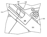
도 7은 그 출구 포트를 도시하는 도 2에 도시된 토너 카트리지의 전방 부위의 사시도이다.
도 8a 및 도 8b는 예시적인 일 실시예에 따른, 각각 폐쇄 위치와 개방 위치에 있는 토너 카트리지용 셔터 어셈블리의 사시도이다.
도 9a 및 도 9b는 도 8a 및 도 8b에 도시된 셔터 어셈블리의 분해도이다.
도 10은 예시적인 제 1 실시예에 따른, 셔터가 폐쇄되어 있는 로킹 위치의 셔터 로크 메커니즘을 도시하기 위해 단부 캡을 제거한 상태의 도 2에 도시된 토너 카트리지의 측면도이다.
도 11은 셔터가 폐쇄되어 있는 언로킹 위치의 셔터 로크 메커니즘을 도시하는 도 10에 도시된 토너 카트리지의 측면도이다.
도 12는 셔터가 개방되어 있는 언로킹 위치의 셔터 로크 메커니즘을 도시하는 도 10 및 도 11에 도시된 토너 카트리지의 측면도이다.
도 13은 외측 연결장치가 눌렸을 때 내측 연결장치가 셔터를 개방하는 것을 허용하도록 외측 연결장치 상의 캐치부의 경로 내에 있는 내측 연결장치를 도시하는 언로킹 위치에 셔터 로크 메커니즘이 위치해 있는 경우의 도 10 내지 도 12에 도시된 토너 카트리지의 상세도이다.
도 14는 셔터를 개방하지 않고 외측 연결장치가 눌리는 것을 허용하는 로킹 위치에 있는 셔터 로크 메커니즘을 도시하는 도 10 내지 도 13에 도시된 토너 카트리지의 측면도이다.
도 15는 셔터를 개방하지 않고 외측 연결장치가 눌리는 것을 허용하도록 외측 연결장치 상의 캐치부 아래로 이격된 내측 연결장치를 도시하는 로킹 위치에 셔터 로크 메커니즘이 위치해 있는 경우의 도 10 내지 도 14에 도시된 토너 카트리지의 상세도이다.
도 16은 도 2에 도시된 토너 카트리지 및 이미징 유닛의 상부 사시도이다.
도 17은 토너 카트리지가 이미징 유닛에 더 가깝게 전진되어 있는 도 16의 17-17 선을 따라 취한 토너 카트리지 및 이미징 유닛의 단면도이다.
도 18은 화상 형성 장치에 로딩되어 있는, 도 2에 도시된 토너 카트리지의 측면도이다.
도 19는 다양한 인터페이스 특징부들의 맞물림을 도시하는 화상 형성 장치 내에서 그 최종 위치에 있는 도 2에 도시된 토너 카트리지의 측면도이다.
도 20a 내지 도 20c는 예시적인 일 실시예에 따른 화상 형성 장치 내의 해당 삽입 경로를 전진하는 토너 카트리지 상의 제 1 윙 가이드(wing guide)의 순차적인 도면이다.
도 21a 내지 도 21c는 예시적인 일 실시예에 따른 화상 형성 장치 내의 해당 삽입 경로를 전진하는 토너 카트리지 상의 제 2 윙 가이드의 순차적인 도면이다.
도 22a 내지 도 22c는 예시적인 일 실시예에 따른 화상 형성 장치 내로 토너 카트리지가 삽입될 때의 도 2의 22-22 선을 따라 취한 토너 카트리지의 레그(leg)의 순차적인 단면도이다.
도 23은 예시적인 제 2 실시예에 따른 토너 카트리지 및 이미징 유닛의 사시도이다.
도 24 및 도 25는 도 23에 도시된 토너 카트리지의 추가적인 사시도이다.
도 26은 예시적인 제 2 실시예에 따른 셔터가 폐쇄된 상태의 로킹 위치에 있는 셔터 로크 메커니즘을 나타내기 위해 단부 캡을 제거한 상태의 도 23에 도시된 토너 카트리지의 측면도이다.
도 27은 도 23에 도시된 토너 카트리지 및 이미징 유닛의 상부 사시도이다.
도 28은 토너 카트리지가 이미징 유닛에 더 가깝게 전진해 있는, 도 27의 28-28 선을 따라 취한 토너 카트리지 및 이미징 유닛의 단면도이다.BRIEF DESCRIPTION OF THE DRAWINGS The foregoing and other features and advantages of various embodiments and the manner of achieving them will become more apparent and better understood with reference to the accompanying drawings.
1 is a block diagram of an imaging system in accordance with an exemplary embodiment.
2 is a perspective view of a toner cartridge and an imaging unit according to an exemplary embodiment;
Figs. 3 and 4 are further perspective views of the toner cartridge shown in Fig. 2. Fig.
Figs. 5 and 6 are exploded views of the toner cartridge shown in Fig. 2 showing the reservoir holding the toner therein.
Fig. 7 is a perspective view of the front portion of the toner cartridge shown in Fig. 2 showing its exit port. Fig.
8A and 8B are perspective views of a shutter assembly for a toner cartridge in an open position and a closed position, respectively, according to an exemplary embodiment.
Figures 9A and 9B are exploded views of the shutter assembly shown in Figures 8A and 8B.
Figure 10 is a side view of the toner cartridge shown in Figure 2 with the end cap removed to show the shutter lock mechanism in the locked position in which the shutter is closed, according to the first exemplary embodiment;
11 is a side view of the toner cartridge shown in Fig. 10 showing the shutter locking mechanism in the unlocking position in which the shutter is closed; Fig.
12 is a side view of the toner cartridge shown in Figs. 10 and 11 showing a shutter lock mechanism in an unlocking position in which the shutter is open; Fig.
Figure 13 is a side elevational view of Figure 10 when the shutter locking mechanism is located in the unlocking position showing the inner connecting device in the path of the catch portion on the outer connecting device to allow the inner connecting device to open the shutter when the outer connecting device is depressed Fig. 12 is a detailed view of the toner cartridge shown in Fig.
Figure 14 is a side view of the toner cartridge shown in Figures 10-13 showing a shutter lock mechanism in a locked position that allows the outer connecting device to be depressed without opening the shutter.
15 is a perspective view of the shutter locking mechanism shown in Figs. 10 to 14 when the shutter locking mechanism is located in the locking position showing the inner connecting device spaced below the catch portion on the outer connecting device to allow the outer connecting device to be depressed without opening the shutter Fig.
16 is a top perspective view of the toner cartridge and the imaging unit shown in Fig.
17 is a cross-sectional view of the toner cartridge and the imaging unit taken along line 17-17 of Fig. 16 with the toner cartridge advancing closer to the imaging unit.
18 is a side view of the toner cartridge shown in Fig. 2, which is loaded in the image forming apparatus.
Figure 19 is a side view of the toner cartridge shown in Figure 2 in its final position within the image forming apparatus showing engagement of various interface features.
20A to 20C are sequential views of a first wing guide on a toner cartridge advancing a corresponding insertion path in an image forming apparatus according to an exemplary embodiment.
21A to 21C are sequential views of a second wing guide on a toner cartridge advancing a corresponding insertion path in an image forming apparatus according to an exemplary embodiment.
22A to 22C are sequential sectional views of the legs of the toner cartridge taken along line 22-22 of FIG. 2 when the toner cartridge is inserted into the image forming apparatus according to an exemplary embodiment.
23 is a perspective view of the toner cartridge and the imaging unit according to the second exemplary embodiment.
Figs. 24 and 25 are additional perspective views of the toner cartridge shown in Fig. 23. Fig.
Figure 26 is a side view of the toner cartridge shown in Figure 23 with the end cap removed to illustrate the shutter lock mechanism in a locked position in which the shutter according to the second exemplary embodiment is closed.
27 is a top perspective view of the toner cartridge and the imaging unit shown in Fig.
Figure 28 is a cross-sectional view of the toner cartridge and imaging unit taken along line 28-28 of Figure 27 with the toner cartridge advancing closer to the imaging unit.
하기의 설명 및 도면은 당업자가 본 발명을 충분히 실시할 수 있게 하는 실시예들을 예시한다. 본 개시물이 하기의 설명에 기술되거나 또는 도면들에 예시된 부품들의 구성 및 배치구조의 상세에 제한되는 것은 아니라는 점을 이해해야 한다. 본 발명은 다른 실시예들일 수 있으며, 다양하게 실행 또는 수행될 수 있다. 예컨대, 다른 실시예들은 구조적인, 발생순의, 전기적인, 절차적인 및 다른 변화들을 포함할 수 있다. 예시들은 단지 가능한 변경들의 전형이다. 개개의 부품들 및 기능들은 명확히 요구되지 않는 한 선택적인 것이며, 작동 순서도 바뀔 수 있다. 몇몇 실시예의 부위들 및 특징부들은 다른 것들에 포함되거나 대체될 수 있다. 본 출원의 범위는 첨부된 청구항들 및 모든 가용 등가물을 포함한다. 따라서, 하기의 설명은 제한된 의미로 취해지지 않아야 하고, 본 발명의 범위는 첨부된 청구항들에 의해 규정된다.
The following description and drawings illustrate embodiments which enable those skilled in the art to practice the present invention fully. It should be understood that this disclosure is not limited to the details of construction and arrangement of parts described in the following description or illustrated in the drawings. The present invention may be implemented by other embodiments and may be carried out or carried out in various ways. For example, other embodiments may include structural, generative, electrical, procedural, and other changes. The examples are merely exemplary of possible changes. The individual components and functions are optional unless explicitly required, and the operating sequence may also change. The portions and features of some embodiments may be included or substituted in others. The scope of the present application includes the appended claims and any available equivalents. Accordingly, the following description is not to be taken in a limiting sense, and the scope of the present invention is defined by the appended claims.
또한, 본원에 사용된 어법 및 용어는 설명을 위한 것이지 제한을 고려한 것이 아님을 이해해야 한다. 본원의 "포함하는(including)", "구성하는(comprising)", 또는 "갖는(having)"의 용도 및 그 변경들은 그 아래에 열거된 항목들 및 그 등가물들 뿐만 아니라 추가적인 항목들을 포함하는 것을 의미한다. 달리 제한하지 않는 한, 본원의 "연결된(connected)", "결합된(coupled)", 및 "장착된(mounted)"이라는 용어들 및 그 변경들은 폭넓게 사용되고, 직간접적인 연결, 결합, 및 장착을 포함한다. 또한, "연결된" 및 "결합된"이라는 용어들과 그 변경들은 물리적이거나 기계적인 연결 또는 결합에 한정되는 것은 아니다.
It is also to be understood that the phraseology and terminology employed herein is for the purpose of description and not of limitation. The use of "including", "comprising", or "having" and variations thereof herein may include additional items as well as items listed below and their equivalents it means. Unless otherwise limited, the terms "connected "," coupled ",and" mounted ", as well as variations thereof, of the present application are used interchangeably, . Also, the terms "connected" and "coupled ", and variations thereof, are not limited to physical or mechanical connections or couplings.
"상(top)", "하(bottom)", "전(front)", "후(back)", "뒤(rear)" 및 "측(side)", "밑(under)", "아래(below)", "아래쪽(lower)", "위(over)", "위쪽(upper)" 등의 공간과 관련된 용어들은 용이한 기재를 위해 일 요소의 제 2 요소에 대한 위치관계를 설명하는데 사용된다. 이들 용어는 화상 형성 장치 내부의 그 의도한 작업 위치에서의 요소의 위치를 참조하는데 일반적으로 사용된다. 또한, "제 1(first)", "제 2(second)" 등의 용어는 다양한 요소들, 구역들, 구간들 등을 기술하는데 사용되며, 제한하려는 것이 아니다. 본원에 사용된 "화상(image)"이라는 용어는 문자, 도식, 또는 그 조합의 임의의 인쇄된 형태 또는 디지털 형태를 포함한다. 유사한 용어들은 상세한 설명 전반에서 유사한 요소들을 의미한다.
The terms "top", "bottom", "front", "back", "rear" and "side" Terms related to space, such as "below", "lower", "over", "upper", etc. describe the positional relationship of the element to the second element . These terms are generally used to refer to the position of the element in its intended working position inside the image forming apparatus. Also, the terms "first "," second ", and the like are used to describe various elements, regions, intervals, and the like, and are not intended to be limiting. The term " image "as used herein includes any printed or digital form of letters, schemas, or combinations thereof. Like terms refer to similar elements throughout the description.
이제, 도면들, 특히 도 1을 참조하면, 예시적인 일 실시예에 따른 이미징 시스템(20)의 블럭도가 도시되어 있다. 이미징 시스템(20)은 화상 형성 장치(22) 및 컴퓨터(24)를 포함한다. 화상 형성 장치(22)는 통신 회선(26)을 통해 컴퓨터(24)와 통신한다. 본원에 사용된 바와 같은, "통신 회선(communications link)"이라는 용어는 일반적으로 다수의 구성요소들간의 전자 통신을 가능하게 하며 유선 또는 무선 기술을 이용해서 작동할 수 있는 임의의 구조를 의미하고, 인터넷을 통한 통신을 포함할 수 있다.
Referring now to the drawings, and in particular to Figure 1, there is shown a block diagram of an
도 1에 도시된 예시적인 실시예에 있어서, 화상 형성 장치(22)는 컨트롤러(28), 인쇄 엔진(30), 레이저 스캔 유닛(LSU)(31), 이미징 유닛(32), 토너 카트리지(35), 유저 인터페이스(36), 매체 이송 시스템(38), 매체 입력 트레이(39) 및 스캐너 시스템(40)을 포함하는 다기능 기기(때때로, 일체형(AIO) 장치라고도 함)이다. 화상 형성 장치(22)는, 예컨대 유니버설 시리얼 버스(USB), 이더넷(Ethernet) 또는 IEEE 802.xx 등의 표준 통신 프로토콜을 통해 컴퓨터(24)와 통신할 수 있다. 화상 형성 장치(22)는, 예컨대 통합형 스캐너 시스템(40) 또는 독립형 전자사진 프린터를 포함하는 전자사진 프린터/복사기일 수 있다.
1, the
컨트롤러(28)는 프로세서 유닛 및 연관 메모리(29)를 포함하고, 하나 이상의 주문형 집적 회로(ASICs)로서 형성될 수 있다. 메모리(29)는, 예컨대 랜덤 액세스 메모리(RAM), 리드 온리 메모리(ROM), 플래시 메모리 및/또는 비휘발성 RAM(NVRAM)과 같은 임의의 휘발성 또는 비휘발성 메모리 또는 그 조합일 수 있다. 대안으로서, 메모리(29)는 별도의 전자 메모리(예컨대, RAM, ROM, 및/또는 NVRAM), 하드 드라이브, CD 또는 DVD 드라이브, 또는 컨트롤러(28)용으로 편리한 임의의 메모리 디바이스 형태로 이루어질 수 있다. 컨트롤러(28)는, 예컨대 프린터 및 스캐너 병용 컨트롤러일 수 있다.
도시된 예시적인 실시예에 있어서, 컨트롤러(28)는 통신 회선(50)을 통해 인쇄 엔진(30)과 통신한다. 컨트롤러(28)는 통신 회선(51)을 통해 이미징 유닛(32) 및 그 처리 회로(44)와 통신한다. 컨트롤러(28)는 통신 회선(52)을 통해 토너 카트리지(35) 및 그 처리 회로(45)와 통신한다. 컨트롤러(28)는 통신 회선(53)을 통해 매체 이송 시스템(38)과 통신한다. 컨트롤러(28)는 통신 회선(54)을 통해 스캐너 시스템(40)과 통신한다. 유저 인터페이스(36)는 통신 회선(55)을 통해 컨트롤러(28)에 통신 가능하게 결합된다. 처리 회로(44, 45)는, 제각기 이미징 유닛(32) 및 토너 카트리지(35)와 관련된 인증 기능, 안전 및 가동 인터로크, 작동 파라미터 및 사용 정보를 제공할 수 있다. 컨트롤러(28)는 인쇄 및 스캔 데이터를 처리하고, 인쇄 동안 인쇄 엔진(30)을, 그리고 스캐닝 동안 스캐너 시스템(40)을 작동시킨다.
In the illustrated exemplary embodiment, the
옵션으로서의 컴퓨터(24)는, 예컨대 RAM, ROM, 및/또는 NVRAM과 같은 메모리(60), 키보드 및/또는 마우스와 같은 입력 장치(62), 및 디스플레이 모니터(64)를 포함하는 퍼스널 컴퓨터일 수 있다. 컴퓨터(24)는 프로세서, 입력/출력(I/O) 인터페이스를 또한 포함하고, 하드 드라이브, CD-ROM 및/또는 DVD 유닛(도시되지 않음)과 같은 적어도 하나의 대량 데이터 저장 장치를 포함할 수 있다. 또한, 컴퓨터(24)는 퍼스널 컴퓨터 외에, 예컨대 태블릿 컴퓨터, 스마트폰, 또는 그 밖의 전자 기기와 같은, 화상 형성 장치(22)와 통신 가능한 장치일 수도 있다.
The computer 24 as an optional component may be a personal computer including a memory 60 such as RAM, ROM, and / or NVRAM, an
도시된 예시적인 실시예에 있어서, 컴퓨터(24)는 화상 형성 장치(22)를 위한 이미징 드라이버(66), 예컨대 프린터/스캐너 드라이버 소프트웨어로서 기능하는 프로그램 명령어들을 포함하는 소프트웨어 프로그램을 그 메모리에 포함한다. 이미징 드라이버(66)는 통신 회선(26)을 통해 화상 형성 장치(22)의 컨트롤러(28)와 통신하게 된다. 이미징 드라이버(66)는 화상 형성 장치(22)와 컴퓨터(24) 사이의 통신을 가능하게 한다. 이미징 드라이버(66)의 일 양태는, 예컨대 형식화된 인쇄 데이터를 화상 형성 장치(22)에, 특히 인쇄 엔진(30)에 제공해서 화상을 인쇄하는 것일 수 있다. 이미징 드라이버(66)의 다른 양태는, 예컨대 스캐너 시스템(40)으로부터의 스캐닝된 데이터의 수집을 가능하게 하는 것일 수 있다.
In the illustrated exemplary embodiment, the computer 24 includes in its memory a software program including program instructions that function as an imaging driver 66 for the
어떤 경우에는, 화상 형성 장치(22)를 독립형 모드로 작동시키는 것이 바람직할 수 있다. 독립형 모드에 있어서는, 화상 형성 장치(22)가 컴퓨터(24) 없이 기능할 수 있다. 그래서, 독립형 모드에서의 작동시에 인쇄 및/또는 스캔 기능을 수용하기 위해 화상 형성 장치(22)의 컨트롤러(28)에 이미징 드라이버(66)의 전부 또는 일부, 또는 유사한 드라이버가 위치될 수 있다.
In some cases, it may be desirable to operate the
인쇄 엔진(30)은 레이저 스캔 유닛(LSU)(31), 토너 카트리지(35), 이미징 유닛(32), 및 정착기구(fuser)(37)를 포함하고, 모두 화상 형성 장치(22) 내부에 장착된다. 이미징 유닛(32)은 화상 형성 장치(22)에 분리 가능하게 장착되고, 토너 섬프(sump) 및 토너 전달 시스템을 수용하는 현상기 유닛(34)을 포함한다. 토너 전달 시스템은 토너를 토너 섬프로부터 현상기 롤에 제공하는 토너 애더 롤을 포함한다. 닥터 블레이드는 현상기 롤의 표면 상에 계량된 균일한 토너층을 제공한다. 이미징 유닛(32)은 광전도 드럼 및 폐토너 제거 시스템을 수용하는 클리너 유닛(33)을 또한 포함한다. 또한, 토너 카트리지(35)는 이미징 유닛(32)의 현상기 유닛(34)과의 결합 관계로 이미징 유닛(32)에 분리 가능하게 장착된다. 토너 카트리지(35) 상의 출구 포트는 토너를 토너 카트리지(35)로부터 주기적으로 전달될 수 있게 하는 현상기 유닛(34) 상의 입구 포트와 연통해서 현상기 유닛(34) 내의 토너 섬프에 재공급한다.
The print engine 30 includes a laser scanning unit (LSU) 31, a
전자사진 인쇄 프로세스는 본 기술분야에 잘 알려져 있기 때문에, 여기서는 간략히 기술한다. 인쇄 작업 동안, 레이저 스캔 유닛(31)은 클리너 유닛(33) 내의 광전도 드럼 상에 잠상을 생성한다. 토너는 현상기 유닛(34) 내의 토너 섬프로부터 현상기 롤에 의해 광전도 드럼 상의 잠상에 전달되어 계조 화상(toned image)을 생성한다. 이후, 계조 화상은 인쇄를 위해 매체 입력 트레이(39)로부터 이미징 유닛(32)에 수용된 매체 시트에 전달된다. 토너 잔류물은 폐토너 제거 시스템에 의해 광전도 드럼으로부터 제거된다. 토너 화상은 정착기구(37) 내의 매체 시트에 본딩되고 나서, 출력 장소로 또는 듀플렉서(duplexer), 스테이플러(stapler) 또는 천공 펀치(hole-punch)와 같은 하나 이상의 마감 옵션들로 보내진다.
Since the electrophotographic printing process is well known in the art, it is briefly described herein. During the printing operation, the laser scanning unit 31 generates a latent image on the photoconductive drum in the cleaner unit 33. [ The toner is transferred from the toner sump in the developing unit unit 34 to the latent image on the photoconductive drum by the developer roll to produce a toned image. Thereafter, the gradation image is transferred from the
이제, 도 2를 참조하면, 예시적인 일 실시예에 따른 토너 카트리지(100) 및 이미징 유닛(200)이 도시된다. 이미징 유닛(200)은 공통 프레임(206) 상에 장착된 현상기 유닛(202) 및 클리너 유닛(204)을 포함한다. 상술한 바와 같이, 이미징 유닛(200) 및 토너 카트리지(100)는 각각 화상 형성 장치(22)에 분리 가능하게 설치된다. 이미징 유닛(200)이 먼저 슬라이드식으로 화상 형성 장치(22)에 삽입된다. 이후, 토너 카트리지(100)가, 도 2에 도시된 화살표로 지시된 바와 같이 이미징 유닛(200)의 현상기 유닛(202)과의 결합 관계로, 화상 형성 장치(22) 내로 및 프레임(206) 상으로 삽입된다. 이 배치구조로 인해, 비어 있는 토너 카트리지 교체시에 이미징 유닛(200)을 분리할 필요 없이 토너 카트리지(100)를 용이하게 분리 및 재삽입할 수 있다. 또한, 이미징 유닛(200)은 현상기 유닛(202), 클리닝 유닛(204) 또는 프레임(206)과 연관된 부품들을 유지, 보수 또는 교체하기 위해, 또는 매체 잼(jam)을 해소하기 위해, 필요에 따라 용이하게 분리될 수 있다.
Referring now to Figure 2, there is shown a
도 2 내지 도 5를 참조하면, 토너 카트리지(100)는 다량의 토너를 내부에 유지하는 밀폐형 리저버(104)(도 5 참조)를 갖는 하우징(102)을 포함한다. 하우징(102)은 베이스(108) 상에 장착된 상부 또는 덮개(106)를 갖는 것으로 보일 수 있다. 베이스(108)는 인접해 있는 전방 및 후방 벽(114, 116)에 연결된 제 1 및 제 2 측벽(110, 112)을 포함한다. 일 실시예에 있어서, 상부(106)는 베이스(108)에 초음파 용접되어서, 밀폐형 리저버(104)를 형성한다. 제 1 및 제 2 단부 캡(118, 120)은 제각기 측벽(110, 112)에 장착된다. 제 1 및 제 2 단부 캡(118, 120)은 제위치에 스냅식으로 끼워맞춰지거나 또는 스크루 또는 다른 체결장치에 의해 부착될 수 있다. 핸들(122)은 토너 카트리지(100)의 상부(106) 또는 베이스(108) 상에 제공되어서, 이미징 유닛(200) 및 화상 형성 장치(22)에 대한 토너 카트리지(100)의 삽입 및 분리를 도울 수 있다. 도 6에 도시된 바와 같이, 토너 카트리지(100)에 토너를 충전하는데 사용되는 충전 포트(124)가 측벽(112)에 제공된다. 충전 후에는, 충전 포트(124)가 플러그(126) 및/또는 캡(128)에 의해 폐쇄된다.
Referring to Figures 2 to 5, the
도 5를 참조하면, 단부 캡(118)과 측벽(110) 사이에 형성된 공간 내에 다양한 드라이브 기어들이 수용된다. 메인 인터페이스 기어(130)는 메인 인터페이스 기어(130)에 토크를 제공하는 화상 형성 장치(22) 내의 드라이브 시스템에 맞물린다. 메인 인터페이스 기어(130)의 일부분은 측벽(110)과 단부 캡(118) 사이에서 토너 카트리지(100)의 전방 부위 상에 노출된다(도 2). 보다 상세하게 후술하는 바와 같이, 단부 캡(120)과 측벽(112) 사이에 형성된 공간 내에는 다양한 연결장치들이 수용된다. 하나 이상의 패들(paddle)(134)은, 토너 리저버(104) 내부에서, 패들(들)(134)의 드라이브 샤프트(136)의 제 1 및 제 2 단부가 제각기 측벽(110, 112) 내의 정렬 개구들을 통해 연장되는 상태로 회전 가능하게 장착된다. 드라이브 샤프트(136)의 축선은 메인 인터페이스 기어(130)의 축선으로부터 후방으로 이격되어 아래에 위치된다. 드라이브 기어(138)는 직접 또는 하나 이상의 중간 기어를 통해 메인 인터페이스 기어(130)와 맞물리는 드라이브 샤프트(136)의 제 1 단부 상에 제공된다. 측벽(110, 112)을 관통하는, 드라이브 샤프트(136)의 각 단부 상에는 부싱들이 제공될 수 있다. 그래서, 측벽(110)을 토너 카트리지(100)의 "구동(drive)" 또는 "종동(driven)" 측부라고도 할 수 있다.
5, various drive gears are received within a space formed between the
도 5 및 도 6을 참조하면, 제 1 및 제 2 단부(140a, 140b)와 나선형 스크루 플라이트(140c)를 갖는 오거(140)는 측벽들(110, 112) 사이에서 전방 벽(114)의 폭을 따라 연장되는 채널(142) 내에 위치된다. 채널(142) 및 오거(140)의 축선은 드라이브 샤프트(136)의 축선 위쪽이되, 메인 인터페이스 기어(130)의 축선 아래쪽에 위치된다. 또한, 채널(142) 및 오거(140)의 축선은 드라이스 샤프트(136) 및 메인 인터페이스 기어(130)의 축선들로부터 전방으로 이격된다. 채널(142)은 전방 벽(114)의 일부로서 일체로 성형되거나, 또는 전방 벽(114)에 부착되는 별도의 부품으로서 형성될 수 있다. 토너 카트리지(100)가 화상 형성 장치(22)에 설치될 때, 채널(142)은 토너 카트리지(100)와 함께 방위가 수평으로 되는 것이 보통이다. 오거(140)의 제 1 단부(140a)는 측벽(110)을 통해 연장되고, 드라이브 기어(144)는 직접 또는 하나 이상의 중간 기어를 통해 메인 인터페이스 기어(130)와 맞물리는 제 1 단부(140a) 상에 제공된다. 채널(142)은 개방부(142a) 및 밀폐부(142b)를 포함한다. 개방부(142a)는 토너 리저버(104)에 대하여 개방되고, 측벽(110)으로부터 오거(140)의 제 2 단부(140b)를 향해 연장된다. 채널(142)의 밀폐부(142b)는 측벽(112)으로부터 연장되고, 셔터 어셈블리(150)(도 7 참조) 및 오거(140)의 제 2 단부(140b)를 에워싼다. 패들(들)(134)이 회전하면, 토너가 토너 리저버(104)로부터 채널(142)의 개방부(142a)로 전달된다. 오거(140)는 드라이브 기어(144)에 의해 회전되어, 채널(142)에 수용된 토너를 셔터 어셈블리(150)에 전달한다. 셔터 어셈블리(150)는, 전방 벽(114)에 제공된 도 7에 도시된 출구 포트(152)를 통해 토너가 토너 카트리지(100)를 나가는 것을 허용할지를 조절한다. 출구 포트(152)는, 출구 포트(152)를 통한 중력에 의한 토너 유출을 돕도록, 하향을 향하는 채널(142)의 하부에 배치된다.
5 and 6, an
셔터 어셈블리(150)는 도 8a, 도 8b, 도 9a 및 도 9b에 보다 상세히 도시된다. 셔터 어셈블리(150)는 도 8a 및 도 9a에 도시된 폐쇄 위치와 도 8b 및 도 9b에 도시된 개방 위치 사이에서 회전 가능한 셔터(154)를 포함한다. 셔터(154)는 내부에 오거(140)의 제 2 단부(140b)를 수용하는 개방 단부(154a)를 포함한다. 오거(140)가 회전하면, 토너가 채널(142)로부터 셔터(154)에 전달된다. 셔터(154)는 셔터(154) 내의 내부 채널에 의해 개방 단부(154a)에 연결되는 방사상 개구(154b)를 포함한다. 방사상 개구(154b)는, 보다 상세히 후술하는 바와 같이, 토너가 출구 포트(152)를 통해 토너 카트리지(100)를 나가는 것을 허용한다.
The
보유 부재(156)는 토너 카트리지(100)의 측벽(112)에 장착된다(도 7 참조). 도시된 예시적인 실시예에 있어서는, 보유 부재(156)가 하우징(102)에 부착된 별도의 부품이지만, 보유 부재(156)는 하우징(102)의 일부로서 일체로 성형될 수도 있다. 보유 부재(156)는 셔터(154)의 폐쇄 단부(154c)를 수용하는 부싱(158)을 포함한다. 셔터(154)의 폐쇄 단부(154c)는 셔터(154)를 개폐하는 레버(160)에 연결된다. 도시된 예시적인 실시예에 있어서는, 셔터(154)의 폐쇄 단부(154c)가 키(162)를 포함하고, 레버(160)가 상응하는 키홈(keyway)(164)을 포함한다. 키(162) 및 키홈(164)은, 레버(160)의 회전이 셔터(154)를 개폐하도록, 셔터(154)를 레버(160)에 결합한다. 이 구성은 레버(160)가 키를 포함하고 폐쇄 단부(154c)가 상응하는 키홈을 포함하도록 뒤바뀔 수 있음을 이해할 것이다. 도시된 실시예에 있어서는, 키홈(164)을 통과하는 체결장치(166) 및 폐쇄 단부(154c) 내의 나사 구멍(168)에 의해 레버(160)가 폐쇄 단부(154c)에 연결되고 있지만, 레버(160) 및 셔터(154)는 스냅식으로 함께 끼워맞추는 등의 임의의 적절한 수단에 의해 연결될 수 있다. 레버(160)의 말단부에는 포스트(170)가 제공된다.
The holding
레버(160)가 도 8a 및 도 9a에 도시된 제 1 위치에 있을 때에는, 셔터(154)는 토너가 토너 카트리지(100)를 나가는 것을 방지하기 위해 방사상 개구(154b)가 채널(142)의 밀폐부(142b)의 내부면에 대하여 위치되는 상태의 폐쇄 위치에 있다. 레버(160)가 도 8b 및 도 9b에 도시된 제 2 위치로 회전하면, 셔터(154)는 토너가 토너 카트리지(100)를 나가는 것을 허용하는 출구 포트(152)와 방사상 개구(154b)가 정렬되는 개방 위치로 회전한다. 셔터(154)가 개방 위치에 있을 때에는, 패들(들)(134) 및 오거(140)를 원하는 만큼 회전시킴으로써 토너가 토너 카트리지(100)의 리저버(104)로부터 이미징 유닛(200)으로 전달될 수 있다. 구체적으로, 패들(들)(134)이 회전하면, 토너가 토너 리저버(104)로부터 채널(142)의 개방부(142a)로 전달된다. 오거(140)가 회전하면, 채널(142)에 수용된 토너가 개방 단부(154a)를 통해 셔터(154)에 전달된다. 토너는 셔터(154) 내의 내부 채널을 통해 방사상 개구(154b) 및 출구 포트(152)로부터 현상기 유닛(202)(도 2 참조) 내의 상응하는 입구 포트(208)를 통과한다.
When the
도 10은 측벽(112)과 단부 캡(120) 사이에 수용된 예시적인 셔터 로크 메커니즘(300)을 보다 명확하게 나타내기 위해 단부 캡(120)을 분리한 카트리지(100)의 측면도를 도시한다. 셔터 로크 메커니즘(300)은 셔터(154)를 개폐하기 위해 레버(160)를 작동시키는 셔터 연결장치(310), 및 토너 카트리지(100)가 화상 형성 장치(22) 내부에 설치되어 이미징 유닛(200)과 결합되지 않는 한 셔터(154)의 개방을 방지하는 인터로크(330)를 포함한다. 이 실시예에 있어서, 셔터 연결장치(310)는 외측 연결장치(312) 및 내측 연결장치(314)를 포함한다. 일 형태에 있어서의 외측 연결장치(312)는 외측 및 내측 측벽(320, 322)을 제각기 갖는 포크형이고, 도시된 바와 같이 덮개(106)에 이은 단부 캡(120)의 후방 부위와 같이, 하우징(102)의 외부 부위에서 후방 지향 개구(175)(마찬가지로 도 2 내지 도 4 참조)를 통해 노출되는 버튼형 영역과 같은 맞물림 표면(316)을 포함한다. 내측 연결장치(314)는 일단부가 레버(160)에 연결된다. 도시된 예시적인 실시예에 있어서, 내측 연결장치는 레버(160)로부터 연장되는 포스트(170)를 수용하는 채널(318)을 포함한다. 그러나, 내측 연결장치(314) 및 레버(160)는, 예컨대 내측 연결장치(314)가 포스트를 포함하고 레버(160)가 상응하는 채널을 포함하도록, 포스트/채널 구성을 뒤바꾸는 등의 임의의 적절한 수단에 의해 연결될 수 있다. 내측 연결장치(314)는 레버(160)의 포스트(170)를 중심으로 피벗 가능하다. 외측 연결장치(312) 및 내측 연결장치(314)는 서로 겹치는 세장형 부재이다. 도시된 실시예에 있어서는, 내측 연결장치(314)가 외측 연결장치(312)의 측벽들(320, 322) 사이에서 포크 내에 위치되지만, 이 구성은 필요에 따라 뒤바뀔 수 있다. 외측 연결장치(312)는 맞물림 표면(316)이 노출되는 개구(175)를 향해 스프링(예컨대, 인장 스프링)과 같은 적절한 편향 부재에 의해 편향된다. 유사하게, 내측 연결장치(314)는 셔터(154)가 폐쇄 위치를 향해 편향되도록 편향 부재에 의해 레버(160)로부터 멀리 편향된다.
10 illustrates a side view of the
이 실시예에 있어서는, 인터로크(330)가 그 회전 축선(332)에서 측벽(112)에 피벗 가능하게 부착된다. 인터로크(330)는 축선(332)으로부터 방사상으로 각각 연장되는 제 1 레그(334) 및 제 2 레그(336)를 포함한다. 제 2 레그(336)는 축선(332)으로부터 방사상으로 연장되는 제 1 부위(336a) 및 제 1 부위(336a)에 거의 수직한 각도로 제 1 부위(336a)의 말단부 근처에서 만곡되게 연장되는 제 2 부위(336b)를 포함한다. 제 2 레그(336)의 제 2 부위(336b)는 셔터(154)의 개방을 허용하기 위해 프레임(206) 상의 핀(fin)(210)과 같은 맞물림 특징부(또는 이미징 유닛(200) 상의 다른 맞물림 특징부)에 접촉하는 맞물림 표면(340)을 포함한다. 도 3에 도시된 바와 같이, 핀(210)을 수용하기 위해 베이스(108)의 전방 부위 및/또는 토너 카트리지(100)의 단부 캡(120)에는 전방 지향 슬롯(174)이 제공된다. 슬롯(174)은 유저의 부주의로 인터로크(330)가 언로킹될 가능성을 줄이기 위해 인터로크(330)에 대한 액세스를 제한한다. 다시 도 10을 참조하면, 제 1 레그(334)는 그 말단부에 가요성 부재(342)를 포함한다. 가요성 부재(342)는 내측 연결장치(314)에 대면하는 그 외면 상에 만곡된 맞물림 표면(344)(도 11 참조)을 포함한다. 내측 연결장치(314)의 하면(내측 연결장치(314)의 측벽 뒤에 가려짐)은 맞물림 표면(344) 상에서 가요성 부재(342)에 의해 지지된다. 인터로크(330)는, 보다 상세히 후술되는 바와 같이, 토너 카트리지(100)를 화상 형성 장치(22)에 설치하기 전에 셔터(154)가 개방하는 것을 방지하기 위해 도 10에 도시된 로킹 위치에서 하나 이상의 편향 부재에 의해 편향된다.
In this embodiment, an
도 11을 참조하면, 토너 카트리지(100)가 화상 형성 장치(22)에 삽입되어 이미징 유닛(200)과 결합될 때, 핀(210)은 슬롯(174)에 진입해서 인터로크(330)의 맞물림 표면(340)에 접촉한다. 인터로크(330)에 대한 핀(210)으로부터의 힘은 인터로크(330)에 가해진 편향력을 극복해서, 인터로크를 언로킹 위치까지 시계 방향(도 11에 도시된 바와 같음)으로 회전시키게 되고, 결국 내측 연결장치(314)가 상승한다. 토너 카트리지(100)가 화상 형성 장치(22)에 삽입된 후에, 화상 형성 장치(22)에 대한 액세스 도어가 폐쇄되면, 도 12에 도시된 바와 같이 액세스 도어의 내면으로부터 연장되는(또는 다른 방식으로 액세스 도어에 연결되는) 플런저 또는 다른 돌기는 맞물림 표면(316)을 가압해서 외측 연결장치(312)에 가해진 편향력을 극복하고, 외측 연결장치(312) 및 내측 연결장치(314)를 모두 눌러서 셔터(154)를 개방하도록 레버(160)를 회전시킨다. 맞물림 표면(316)이 가압되면, 외측 연결장치(312)는 도 12에서 화살표에 의해 도시된 방향으로 이동한다. 외측 연결장치(312)는 단부 캡(120) 또는 측벽(112) 상의 상응하는 포스트를 수용하는 세장형 슬롯(346)을 포함한다. 슬롯(346)은 외측 연결장치(312)의 이동 경로를 규정한다. 도 13에 더 상세히 도시된 바와 같이, 인터로크(330)가 핀(210)에 의해 회전된 언로킹 위치에 있을 때, 내측 연결장치(314)는 외측 연결장치(312)의 내측 상면 상의 캐치부(326)의 경로 내로 상승된다. 결과적으로, 외측 연결장치(312)가 눌릴 때, 캐치부(326)는 내측 연결장치(314)의 상부 모서리(328)에 맞물려서 내측 연결장치(314)에 가해진 편향을 극복하는 한편, 내측 연결장치(314)를 외측 연결장치(312)와 함께 전진시켜서, 결국 셔터(154)를 개방하게 된다. 외측 연결장치(312) 및 내측 연결장치(314)가 눌릴 때, 내측 연결장치(314)의 운동은 이동이 엄격하지 않고, 오히려, 내측 연결장치(314)는 하강되고 나서 셔터(154)의 회전 축선을 중심으로 레버(160)가 회전함에 따라 약간 상승한다. 가요성 부재(342)는 약간 휘는 것에 의해 이 하강 및 상승 동작을 수용해서, 내측 연결장치(314)가 그 동작의 결속 또는 재결속 없이 하강하는 것을 허용한다. 이는 외측 연결장치(312) 및 내측 연결장치(314)가 서로 맞물려 있는 상태를 유지하는 것을 돕는다.
11, when the
토너 카트리지(100)가 화상 형성 장치(22)로부터 분리될 때는, 이 수순이 반대로 된다. 화상 형성 장치(22)에 대한 액세스 도어가 개방되면, 외측 연결장치(312) 및 내측 연결장치(314)는 그들의 편향된 위치로 철회되어, 셔터(154)가 폐쇄된다. 유저가 토너 카트리지(100)를 장치에서 분리하면, 핀(210)은 맞물림 표면(340)으로부터 철수되어 인터로크(330)를 반시계 방향(도 10 내지 도 12에 도시된 바와 같음)으로 로킹 위치까지 회전시킨다. 인터로크(330)가 회전하면, 내측 연결장치(314)는 상부 모서리(328)가 캐치부(326)의 경로 아래에 위치할 때까지 내려진다.
When the
도 14를 참조하면, 인터로크(330)가 도 10 및 도 14에 도시된 로킹 위치에 있는 상태에서 맞물림 표면(316)이 가압되는 경우에는, 외측 연결장치(312)가 내측 연결장치(314) 쪽으로 그것을 지나서 눌린다. 도 15에 더 상세히 도시된 바와 같이, 인터로크(330)가 로킹될 때, 내측 연결장치(314)는 외측 연결장치(312)의 내측 상면 상의 캐치부(326) 아래로 이격된다. 결과적으로, 외측 연결장치(312)는 내측 연결장치(314)를 누르지 않고, 그에 따라 셔터(154)를 개방하지 않고 자유롭게 통과한다. 이렇게 해서, 외측 연결장치(312)의 맞물림 표면(316)이 눌려서 인터로크(330)의 맞물림 표면(340)이 맞물리지 않는 한, 셔터 로크 메커니즘(300)은 셔터(154)가 개방되는 것을 방지한다. 이는, 토너 카트리지(100)가 화상 형성 장치(22) 내의 그 최종 위치에서 이미징 유닛(200)과 결합되지 않는 한, 셔터(154)가 개방되는 것을 방지한다. 결과적으로, 맞물림 표면(316)이 가압되는 경우에도 토너 카트리지(100)가 화상 형성 장치(22)로부터 분리되어 있는 상태에서는, 셔터(154)가 폐쇄된 채로 유지된다.
14, when the
이미징 유닛(200)이 존재하지 않는 상태에서 셔터(154)가 개방되었을 경우에는, 토너가 출구 포트(152)를 통해 화상 형성 장치(22)의 내부 영역으로 유출할 수 있게 되어, 잠재적으로 인쇄 결함을 야기하게 된다. 셔터 로크 메커니즘(300)은 이러한 상황이 발생하는 것을 방지한다. 또한, 셔터 로크 메커니즘(300)은, 이미징 유닛(200)이 존재하지 않는 경우에도, 셔터(154)를 개방하지 않고 유저가 화상 형성 장치(22)에 대하여 액세스 도어를 폐쇄할 수 있게 한다. 이미징 유닛(200)이 존재하지 않을 때 외측 연결장치(312)가 내측 연결장치(314)를 자유롭게 통과할 수 없었을 경우에는, 유저가 화상 형성 장치(22)에 대하여 액세스 도어를 폐쇄하려고 하면, 인터로크(330)가 외측 연결장치(312) 및 내측 연결장치(314)의 이동을 방지하게 되기 때문에, 폐쇄할 수 없게 된다. 유저가 액세스 도어를 폐쇄하려고 계속해서 시도하면, 가해진 힘에 따라서는, 토너 카트리지(100)의 로킹 메커니즘(300) 또는 다른 부위를, 또는 화상 형성 장치(22)를 구성하는 하나 이상의 부품을 파손시키게 될 수 있다. 로크 메커니즘(300)은 인터로크(330)가 로크 위치에 있을 때 외측 연결장치(312)가 내측 연결장치(314)를 지나서 주행하는 것을 허용함으로써 이 문제를 다룬다. 또한, 셔터(154)를 개방하기 위해서는 맞물림 표면(316)과 맞물림 표면(340)이 모두 가압될 필요가 있기 때문에, 로크 메커니즘(300)은, 유저가 토너 카트리지(100)로부터 뜻하지 않게 토너를 유출시킬 가능성을 낮춘다.
When the
도 3 및 도 7을 참조하면, 토너 카트리지(100)는 측벽(112) 근처에서 출구 포트(152)로부터 이격된 하우징(102)의 전부(114)로부터 돌출하는 리브(rib) 또는 돌기(176)를 포함한다. 도시된 예시적인 실시예에 있어서는, 돌기(176)가 보유 부재(156)의 일부로서 형성되어 있다. 돌기(176)는 토너가 현상기 유닛(202) 상의 입구 포트(208)에 진입하는 것을 허용할지를 조절하는 셔터(209)(도 16 참조)를 작동시키도록 위치된다. 구체적으로, 토너 카트리지(100)가 화상 형성 장치(22)에 설치되어 현상기 유닛(202)과 결합되면, 돌기(176)는 셔터(209)에 접촉해서 셔터를 개방한다. 토너 카트리지(100)가 현상기 유닛(202)에서 분리되어 화상 형성 장치(22)로부터 분리되면, 돌기(176)는 셔터(209)에서 철수되어 셔터를 폐쇄한다. 도시된 예시적인 실시예에 있어서, 돌기(176)는 전방 벽(114)으로부터 연장되는 전방 돌출부(177) 및 전방 돌출부(177)의 전방에서 옆으로 연장되는 노브(knob)(178)를 포함한다.
3 and 7, the
다시 도 2를 참조하면, 토너 카트리지(100)가 화상 형성 장치(22)에 설치될 때, 그 다양한 인터페이스 특징부들은 이미징 유닛(200) 및 화상 형성 장치(22) 상의 상응하는 인터페이스 특징부들과 정렬되어야 한다. 화상 형성 장치(22) 내의 그 최종 위치에서는, 출구 포트(152)(도 3 참조)가 현상기 유닛(202) 상의 입구 포트(208)와 정렬 및 결합되는 상태로, 토너 카트리지(100)가 이미징 유닛(200)의 프레임(206) 위에 위치된다. 그 최종 위치에 있어서는, 토너 카트리지(100)가 현상기 유닛(202)에 로딩력을 가하지 않는다. 출구 포트(152) 및 입구 포트(208)는 토너 카트리지(100)와 현상기 유닛(202) 사이에서의 토너 누설을 방지하기 위해 정밀하게 정렬되어야 한다. 또한, 메인 인터페이스 기어(130)는 메인 인터페이스 기어(130)에 토크를 제공하는 화상 형성 장치(22) 내의 상응하는 드라이브 기어와 정렬 및 결합되어야 한다. 메인 인터페이스 기어(130)가 오정렬되는 경우에는, 적절한 기어 맞물림이 달성되지 않아서 기어 코깅(gear cogging)을 초래할 수 있다. 단부 캡(118) 상의 커넥터(145) 내부에 위치된 토너 카트리지(100)의 처리 회로(45)용 전기 접점들은 토너 카트리지(100)와 화상 형성 장치(22) 사이의 통신을 허용하기 위해 화상 형성 장치(22) 내의 상응하는 전기 접점들과 정렬 및 결합되어야 한다. 도시된 바와 같이, 커넥터(145)는 화상 형성 장치(22) 내의 상응하는 전기 접점들을 수용하기 위한 전방 지향 개구(145a)를 포함한다. 도시된 예시적인 실시예에 있어서, 단부 캡(120)은 토너 카트리지(100)가 삽입될 때 화상 형성 장치(22) 내의 상응하는 전기 접점들을 개구(145a)를 향해 안내하기 위해 개구(145a)와 정렬되는 테이퍼진 도입부(145b)를 포함한다. 또한, 슬롯(174)은 토너 카트리지(100)가 화상 형성 장치(22)에 삽입될 때 핀(210)을 수용하도록 위치되어야 하고, 개구(175)는 인터로크(330)를 언로킹시키기 위해 화상 형성 장치(22)에 대하여 액세스 도어로부터의 돌기를 수용하도록 위치되어야 한다. 토너 카트리지(100)의 적정한 작동을 보장하기 위해 이들 다양한 인터페이스 지점들의 위치들은 엄격히 제어되어야 한다. 결과적으로, 토너 카트리지(100)는 전후로(도 2의 "x" 방향), 수직으로("y" 방향) 및 좌우 또는 축방향으로("z" 방향) 적절히 위치되어야 한다. 요(yaw)라고도 하는, 토너 카트리지의 삽입 각도("Θ")도 역시 적절한 위치결정을 보장하기 위해 허용 가능한 범위 내로 제어되어야 한다.
2, when the
도 2 및 도 16을 참조하면, 토너 카트리지(100) 및 이미징 유닛(200)은 거친 축방향 위치결정 특징부 및 미세한 축방향 위치결정 특징부를 모두 포함한다. 토너 카트리지(100)는 베이스(108)로부터 하향으로 돌출하는 한 쌍의 레그(146, 148)를 포함한다. 레그들(146, 148)은 단부 캡들(118, 120) 사이에서 서로 축방향 "z"를 따라 이격된다. 레그들(146, 148)은 토너 카트리지의 후방 부위로부터 삽입 방향 "x"에 평행한 전방 벽(114)을 향해 베이스(108)를 따라 연장된다. 레그(148)의 전방 부위는 내부에 슬롯(174)을 포함한다. 이미징 유닛(200)의 프레임(206)은 레그들(146, 148)에 대응하는 한 쌍의 수직 벽(212, 214)을 포함한다. 각각의 수직 벽(212, 214)은, 토너 카트리지(100)가 이미징 유닛(200)을 향해 전진할 때 삽입 방향 "x"에 대하여 바깥쪽으로 각져서 토너 카트리지(100)에 대면하는 베벨형 정면(212a, 214a)을 포함한다. 각각의 수직 벽(212, 214)은 토너 카트리지(100)의 삽입 방향 "x"에 거의 평행한 내면(212b, 214b)을 또한 포함한다. 내면들(212b, 214b)은 제각기 현상기 유닛(202)을 향해 "x" 방향을 따라 정면들(212a, 214a)로부터 안쪽으로 이격된다. 토너 카트리지(100)가 화상 형성 장치(22)에 삽입되면, 정면들(212a, 214a)이 토너 카트리지(100)를 현상기 유닛(202)을 향해 안내하고 축방향 "z"로의 토너 카트리지(100)의 주행을 제한한다. 토너 카트리지(100)가 삽입 동안 축방향 "z"에 있어서 오정렬되면, 그 레그들(146, 148) 중 하나의 외면(146a, 148a)은 수직 벽들(212, 214)의 상응하는 정면(212a 또는 214a)에 접촉하게 된다. 이후, 정면(212a 또는 214a)의 각도는 토너 카트리지(100)를 그 축방향으로 적절히 정렬되도록 가압하게 되고, 이로써 토너 카트리지(100)가 현상기 유닛(202)을 향해 전진할 때 거친 위치 제어가 제공된다.
Referring to Figures 2 and 16, the
토너 카트리지(100)가 더 전진하면, 레그들(146, 148)의 외면들(146a, 148a)은 수직 벽들(212, 214)의 내면들(212b, 214b) 사이에 구속되어, 축방향에 있어서의 토너 카트리지(100)의 주행이 더 제한된다. 도시된 예시적인 실시예에 있어서, 레그(146)의 외면(146a)과 레그(148)의 외면(148a) 사이의 거리는 약 266 mm 내지 약 269 mm 이다. 이들 거친 축방향 제어 특징부들은 도 17에 도시된 엄격하게 제어된 슬롯 및 탭 인터페이스 형태의 미세한 축방향 제어 특징부들로 이어진다. 도 17은 토너 카트리지(100)가 이미징 유닛(200)에 더 가깝게 전진해 있는, 도 16의 17-17 선을 따라 취한 토너 카트리지(100) 및 이미징 유닛(200)의 단면도를 도시한다. 도 17에 도시된 바와 같이, 수직 벽(216)은 축방향 "z"를 따라 수직 벽(212)으로부터 안쪽으로 이격되어, 그 사이에 슬롯(218)이 형성된다. 구체적으로, 슬롯(218)은 수직 벽(212)의 내면(212b)과 수직 벽(216)의 외면(216a) 사이에 형성된다. 토너 카트리지(100)가 현상기 유닛(202)에 더 가깝게 전진되면, 레그(146)의 전방 부위는 프레임(206) 내의 슬롯(218)에 수용되어, 아래에서 더 상세히 기술하는 바와 같이, 슬롯(218)이 토너 카트리지(100)의 축방향 위치를 엄격하게 유지할 수 있게 된다.
When the
도 18 및 도 19를 참조하면, 각각의 단부 캡(118, 120)의 측면은 윙 가이드(180, 190)를 포함한다(단부 캡(120)용 윙 가이드(190)는 도 3 및 도 4를 참조). 각각의 윙 가이드(180, 190)는 그 단부 캡(118, 120)의 후방 부위로부터 그 전방 부위를 향해 연장되는 일반적으로 세장형의 몸체(181, 191)를 포함한다. 윙 가이드들(180, 190)은 실질적으로 서로 평행하다. 토너 카트리지(100)가 화상 형성 장치(22)에 삽입될 때, 윙 가이드(180, 190)는 각각 화상 형성 장치(22)의 내면을 따라 뻗는 상부 및 하부 가이드(72, 74)에 의해 규정된 소정의 삽입 경로(70)를 주행한다. 각각의 윙 가이드(180, 190)의 상면(182, 192)은 그 단부 캡(118, 120)의 후방 부위로부터 그 전방 부위를 향해 연장되는 실질적으로 평평한 후방 부위(182a, 192a)를 포함한다. 또한, 각각의 상면(182, 192)은 제각기 후방 부위(182a, 192a)에 대하여 하향으로 각지는 전방 부위(182b, 192b)도 포함한다. 아래에서 더 상세히 기술되는 바와 같이, 토너 카트리지가 화상 형성 장치(22)에 삽입될 때, 제각기 토너 카트리지(100)의 전방 주행을 제한하는 정지부(183, 193)는 각각의 상면(182, 192)으로부터 수직 상향으로 연장된다. 각각의 윙 가이드(180, 190)는 제각기 그 전방 선단부를 형성하는 테이퍼진 노즈(nose)(184, 194)를 또한 포함한다. 도시된 예시적인 실시예에 있어서, 각각의 개별 윙 가이드(180, 190)의 하면(185, 195)은 화상 형성 장치(22)의 하부 가이드(74)와의 접촉 지점들을 규정하는 3개의 둥근 돌기들(186a, 186b, 186c 및 196a, 196b, 196c)을 포함한다. 윙 가이드들(180, 190)은, 둥근 돌기(186b, 186c 및 196b, 196c)와 결합된 몸체(181, 191)에 의해 형성된 형상 때문에, "도그 본(dog bone)"이라고 인용되기도 한다. 각각의 개별 윙 가이드(180, 190)의 상면(182, 192)은 둥근 돌기들(187a, 187b, 197a 및 197b)의 쌍을 포함한다.
18 and 19, the sides of each
각각의 단부 캡(118, 120)은 개개의 단부 캡(118, 120)의 상부 부위로부터 상향으로 돌출하는 맞물림 표면(172, 173)을 또한 포함한다. 각각의 맞물림 표면(172, 173)은 삽입 동안 이미징 유닛(200)에 대면하는 각진 정면(172a, 173a) 및 삽입 동안 이미징 유닛(200)에 대향하는 각진 후면(172b, 173b)을 포함한다.
Each
도 18을 참조하면, 토너 카트리지(100)가 화상 형성 장치(22)에 처음 삽입되면, 토너 카트리지(100)의 삽입 경로 내로 편향되는 화상 형성 장치(22) 내의 롤러(76)가 맞물림 표면들(172, 173)의 정면들(172a, 173a)에 접촉한다. 롤러(76)에 의해 토너 카트리지(100)에 가해진 힘은 토너 카트리지(100)의 진입을 제어해서, 화상 형성 장치(22) 내로 너무 빠르게 전진하는 것을 방지한다. 또한, 토너 카트리지(100)가 화상 형성 장치(22)에 처음 삽입되면, 윙 가이드들(180, 190)의 하향으로 각진 전방 부위들(182b, 192b) 및 테이퍼진 노즈(184, 194)는 상대적으로 넓은 범위의 허용 삽입 각도(Θ)(또는 요)를 유저에게 제공한다. 토너 카트리지(100)가 전진함에 따라, 삽입 각도는 도시된 바와 같이, 정면들(182, 192) 상의 돌기들(187a, 187b, 197a, 197b) 및 하면들(185, 195) 상의 전방 돌기들(186a, 196a)에 의해 제한된다.
18, when the
도 19를 참조하면, 토너 카트리지(100)가 그 최종 위치로 전진되면, 롤러(76)는 후면(172b, 173b)에 접촉할 때까지 각각의 맞물림 표면(172, 173)의 정점(172c, 173c) 위를 지난다. 롤러(76)에 의해 토너 카트리지(100)의 후면들(172b, 173b)에 가해진 힘은 토너 카트리지(100)를 화상 형성 장치(22) 내의 그 최종 위치까지 가압한다. 토너 카트리지(100)가 전진하면, 정지부들(183, 193)이 화상 형성 장치(22) 내의 상부 가이드(72)에 접촉해서, 토너 카트리지(100)가 더 전진하는 것을 방지하고, 이로써 "x" 방향을 따르는 토너 카트리지(100)의 전후 수평방향 위치결정이 제어된다. "y" 방향을 따르는 토너 카트리지(100)의 수직 위치는 화상 형성 장치(22) 내의 둥근 돌기들(186b, 186c, 196b, 196c)과 하부 가이드(74)들간의 접촉에 의해 제어된다. 구체적으로, 4개의 둥근 돌기(186b, 186c, 196b, 196c) 중 3개는 토너 카트리지(100)의 수직 위치를 결정하는 평면을 규정하는 기준점을 형성한다. 예컨대, 도시된 예시적인 실시예에 있어서, 둥근 돌기들(186b, 186c 및 196b)의 반경들은 동일한 반면, 둥근 돌기(196c)의 반경은 약간 작다. 결과적으로, 이 실시예에 있어서, 둥근 돌기들(186b, 186c 및 196b)은 토너 카트리지(100)의 수직 위치를 제어한다.
19, when the
토너 카트리지(100)의 정확한 위치결정은 토너 카트리지(100)의 다양한 인터페이스 특징부들과 이미징 유닛(200) 및 화상 형성 장치(22) 상의 상응하는 인터페이스 특징부들간의 적절한 정렬을 허용한다. 도시된 바와 같이, 그 최종 위치에 있어서, 토너 카트리지(100)의 출구 포트(152)는 현상기 유닛(202) 상의 입구 포트(208)와 정렬 및 결합된다. 메인 인터페이스 기어(130)는 화상 형성 장치(22) 내의 상응하는 드라이브 기어(78)와 정렬 및 결합된다. 커넥터(145) 내의 처리 회로용 전기 접점들은 화상 형성 장치(22) 내의 커넥터(80) 상의 상응하는 전기 접접들과 정렬 및 결합된다. 토너 카트리지(100)의 위치 제어 특징부들은, 토너 카트리지(100)의 적절한 작동을 보장하기 위해, 이들 인터페이스 지점들이 엄격하게 제어되게 한다. 작동 중에, 맞물림 표면들(172, 173)의 후면들(172b, 173b) 상에 롤러(76)에 의해 가해진 힘은 토너 카트리지(100)를 제위치에 유지해서, 토너 카트리지가 입구 포트(208), 드라이브 기어(78) 또는 전기 접점(80)들로부터 분리되는 것을 방지한다.
The precise positioning of the
도 20a 내지 도 20c, 도 21a 내지 도 21c, 및 도 22a 내지 도 22c는 화상 형성 장치(22) 내로의 토너 카트리지(100)의 삽입을 예시하는 순차적인 도면이다. 도 20a 내지 도 20c 및 도 21a 내지 도 21c는, 토너 카트리지(100)가 화상 형성 장치(22) 내로 삽입될 때, 제각기 삽입 경로(70)에 대한 윙 가이드들(180, 190)의 위치를 도시한다. 도 22a 내지 도 22c는 도 2의 22-22 선을 따라 취한 토너 카트리지(100)의 레그(146)의 단면도를 도시한다. 도 20a, 도 21a 및 도 22a는 토너 카트리지(100)가 화상 형성 장치(22)에 처음에 삽입될 때의 제 1 순차도를 도시한다. 구체적으로, 도 20a 및 도 21a는 제각기, 그들 각각의 삽입 경로(70)에 진입하는 윙 가이드(180, 190)를 도시한다. 도 22a는 프레임(206) 내의 슬롯(218)에 진입하는 레그(146)의 전방 부위(180)를 도시한다. 예시된 바와 같이, 레그(146)의 전방 부위(146b)는 폭방향으로 테이퍼져서 그 전방 선단에서 탭 또는 노즈(146c)를 형성한다. 일 실시예에 있어서, 노즈(146c)의 폭은 약 5 mm 내지 약 9 mm이다. 슬롯(218)은 레그(146)의 전방 부위(146b)를 슬롯(218) 내로 수용 및 안내하는 상응하는 테이퍼진 도입부(220)를 포함한다. 슬롯(218)은 노즈(146c)를 단단히 수용하는 사이즈의 내측 슬롯부(222)를 또한 포함한다. 도 20b, 도 21b 및 도 22b는 토너 카트리지(100)가 화상 형성 장치(22) 내로 더 전진될 때의 제 2 순차도를 도시한다. 도 20b 및 도 21b는 제각기, 그들 각각의 삽입 경로(70)를 따라 더 전진된 윙 가이드들(180, 190)을 도시한다. 도 22b는 슬롯(218) 내에서 더 전진된 레그(146)의 전방 부위(146b)를 도시한다. 도 20c, 도 21c 및 도 22c는 토너 카트리지(100)가 화상 형성 장치(22)에 완전히 삽입되어 현상기 유닛(202)과 결합되어 있는 최종 순차도를 도시한다. 도 20c 및 도 21c는 화상 형성 장치(22) 내의 상응하는 립(lip) 또는 둥근 정지부(82)와 맞물린 정지부들(183, 193)을 도시한다. 정지부(82)들은 삽입 방향에 있어서의 토너 카트리지(100)의 위치를 제어하고, 토너 카트리지(100)가 화상 형성 장치(22)에 지나치게 삽입되지 않게 한다. 또한, 도 20c 및 도 21c는 하부 가이드(74) 상에 위치된 둥근 돌기들(186b, 186c 및 196b) 및 하부 가이드(74)로부터 이격된 둥근 돌기들(186a, 196a 및 196c)을 도시한다. 상술한 바와 같이, 이 실시예에 있어서, 둥근 돌기들(186b, 186c 및 196b)은 토너 카트리지(100)의 수직 위치를 제어하는 평면을 규정한다. 도 22c는 토너 카트리지(100)의 축방향 위치를 제어하기 위해 내측 슬롯부(222)에 단단히 위치된 노즈(146c)를 도시한다.
Figs. 20A to 20C, Figs. 21A to 21C, and Figs. 22A to 22C are sequential views illustrating the insertion of the
도 23 내지 도 25는 예시적인 제 2 실시예에 따른 토너 카트리지(400) 및 상응하는 이미징 유닛(500)을 도시한다. 이미징 유닛(500)은 공통 프레임(506) 상에 장착된 현상기 유닛(502) 및 클리너 유닛(504)을 포함한다. 현상기 유닛(502)은 토너 카트리지(400)로부터 토너를 수용하기 위한 입구 포트(508)를 포함한다. 프레임(506)은 토너 카트리지(400)에서 토너의 유출을 조절하는 셔터를 작동시키기 위한, 상술한 핀(210)과 유사한 돌기(510)를 포함한다. 상술한 바와 같이, 이미징 유닛(500) 및 토너 카트리지(400)는 각각 화상 형성 장치(22)에 분리 가능하게 설치된다. 그 최종 위치에서, 토너 카트리지(400)는 이미징 유닛(500)의 현상기 유닛(502)과 결합 관계에 있다.
23 to 25 illustrate a
토너 카트리지(400)는 베이스(408) 상에 장착된 상부 또는 덮개(406)를 갖는 하우징(402)을 포함한다. 하우징(402)은 상술한 바와 같이, 내부에 토너를 유지하는 밀폐형 리저버를 포함한다. 토너 카트리지(400)의 리저버의 내부 부품들(예컨대, 패들들, 드라이브 샤프트, 채널, 및 오거)은 실질적으로 토너 카트리지(100)에 대하여 상술한 것들과 동일하다. 베이스(408)는 인접하는 전방 및 후방 벽(414, 416)에 연결된 제 1 및 제 2 측벽을 포함한다. 제 1 및 제 2 단부 캡(418, 420)은 제각기 측벽들(단부 캡들(418, 420)들에 의해 가려짐)에 장착된다. 핸들(422)은 필요에 따라 토너 카트리지(400)의 상부(406) 또는 베이스(408) 상에 제공될 수 있다. 메인 인터페이스 기어(430)는 단부 캡(418)과 그 각각의 측벽 사이에서 전방 벽(414) 상에 노출된다. 메인 인터페이스 기어(430)는 메인 인터페이스 기어(430)에 토크를 제공하는 화상 형성 장치(22) 내의 드라이브 시스템과 맞물린다. 토너 카트리지(100)에 대하여 상술한 바와 같이, 단부 캡(418)과 측벽(410) 사이에 형성된 공간 내부에는 다양한 추가적인 드라이브 기어들이 수용된다. 아래에서 더 상세히 기술하는 바와 같이, 단부 캡(420)과 측벽(412) 사이에 형성된 공간 내부에는 다양한 연결장치들이 수용된다. 출구 포트(452)는, 출구 포트(452)를 통한 중력에 의한 토너 유출을 돕도록, 하향을 향하는 배향으로 전방 벽(414) 상에 배치된다. 상술한 셔터 어셈블리(150)는 토너가 출구 포트(452)를 통해 토너 카트리지(400)를 나가는 것을 허용할지를 조절하는데 사용될 수 있다. 또한, 토너 카트리지(400)는 토너 카트리지(400)의 처리 회로용 전기 접점들을 갖는 단부 캡(420) 상에 위치된 커넥터(445)를 포함한다. 커넥터(445)는 화상 형성 장치(22) 내의 상응하는 전기 접점들을 수용하기 위한 전방 지향 개구(445a)를 포함한다. 도시된 예시적인 실시예에 있어서, 단부 캡(420)은 토너 카트리지(400)가 삽입될 때 화상 형성 장치(22) 내의 상응하는 전기 접점들을 개구(445a)를 향해 안내하기 위해 개구(445a)와 정렬되는 테이퍼진 도입부(445b)를 포함한다. 도 24에 도시된 바와 같이, 토너 카트리지(400)는 상술한 바와 같이, 토너가 현상기 유닛(502) 상의 입구 포트(508)에 진입하는 것을 허용할지를 조절하는 셔터(509)(도 27 참조)를 작동시키기 위해, 측벽(412) 근처에서 하우징(402)의 전부(414)로부터 돌출하는 리브 또는 돌기(476)를 포함한다.
The
도 26을 참조하면, 토너 카트리지(400)는 다른 예시적인 실시예에 따른 셔터 로크 메커니즘(600)을 포함할 수 있다. 단부 캡(420)은 셔터 로크 메커니즘(600)을 보다 명확하게 나타내기 위해 도 26에서는 제거되어 있다. 셔터 로크 메커니즘(600)은, 토너 카트리지(400)가 화상 형성 장치(22) 내부에 설치되어 이미징 유닛(500)과 결합되지 않는 한, 상술한 바와 같이 셔터를 개폐하기 위해 레버(460)를 작동시키는 셔터 연결장치(610) 및 셔터가 개방되는 것을 방지하는 인터로크(630)를 포함한다. 이 실시예에 있어서, 셔터 연결장치(610)는 외측 연결장치(612) 및 내측 연결장치(614)를 포함한다. 일 형태에 있어서의 외측 연결장치(612)는 외측 측벽(620) 및 내측 측벽(외측 측벽(620) 뒤에 가려짐)을 갖는 포크형이다. 외측 연결장치(612)는, 도시된 바와 같이 베이스(408)에 이은 단부 캡(420)의 후방 부위와 같이, 하우징(402)의 외부 부위에 대하여 후방 지향 개구(475)(도 25를 또한 참조)를 통해 노출되는 버튼형 영역과 같은 맞물림 표면(616)을 포함한다. 내측 연결장치(614)는 일 단부가 레버(460)에 연결된다. 도시된 예시적인 실시예에 있어서, 내측 연결장치는 레버(460)로부터 연장되는 포스트(470)를 수용하는 채널(618)을 포함하지만, 상술한 바와 같이, 이 연결은 임의의 적절한 수단에 의해 확립될 수 있다. 외측 연결장치(612) 및 내측 연결장치(614)는 서로 겹치는 세장형 부재이다. 도시된 실시예에 있어서, 내측 연결장치(614)는 외측 연결장치(612)의 외측 측벽(620)과 내측 측벽 사이에서 포크 내에 위치되지만, 이 구성은 필요에 따라 뒤바뀔 수 있다. 외측 연결장치(612)는 맞물림 표면(616)이 노출되는 개구(475)를 향해 적절한 편향 부재에 의해 편향된다. 유사하게, 내측 연결장치(614)는, 셔터가 그 폐쇄 위치를 향해 편향되도록, 편향 부재에 의해 레버(460)로부터 멀리 편향된다. 도 10 내지 도 15에 도시된 외측 연결장치(312) 및 내측 연결장치(314)에 대하여 상술한 바와 같이, 외측 연결장치(612)의 내면은, 인터로크(630)가 언로킹될 때에는 내측 연결장치(614)의 일부분에 맞물리지만 인터로크(630)가 로킹될 때에는 내측 연결장치(614)를 해제하는, 캐치부를 포함한다.
Referring to Fig. 26, the
이 실시예에 있어서, 인터로크(630)는 그 회전 축선(632)에서 측벽(412)에 대하여 피벗 가능하게 부착된다. 인터로크(630)는 그 부착 지점(632)으로부터 전방 벽(414)을 향해 측벽(412)을 따라 연장된다. 인터로크(630)는, 셔터의 개방을 허용하기 위해 이미징 유닛(500) 상에서, 돌기(510)와 같은 맞물림 특징부에 접촉하는 만곡된 또는 경사진 맞물림 표면(634)을 포함한다. 또한, 인터로크(630)는, 후술하는 바와 같이 인터로크(630)가 언로킹될 때, 내측 연결장치(614)를 상승시키는 상향 연장 포스트(636)를 포함한다. 인터로크(630)는, 화상 형성 장치(22) 내에 토너 카트리지(400)를 설치하기 전에 셔터가 개방되는 것을 방지하기 위해, 도 26에 도시된 로킹 위치에서 하나 이상의 편향 부재에 의해 편향된다.
In this embodiment, the
상술한 바와 같이, 인터로크(630)가 로킹 위치에 있는 동안 맞물림 표면(616)이 가압되면, 외측 연결장치(612)는 내측 연결장치(614)를 누르지 않고 내측 연결장치(614)를 지나 주행한다. 결과적으로, 셔터는 개방되지 않는다. 이는, 유저가 이미징 유닛(500)이 존재하지 않을 때 화상 형성 장치(22)에 대한 액세스 도어를 폐쇄하거나, 또는 셔터를 개방하지 않고 맞물림 표면(616)을 가압할 수 있게 한다.
As described above, when the
토너 카트리지(400)가 화상 형성 장치(22)에 삽입되어 이미징 유닛(500)과 결합될 때, 돌기(510)와 같은, 이미징 유닛(500) 상의 맞물림 특징부는 인터로크(630)의 맞물림 표면(634)과 접촉한다. 인터로크(630) 상의 맞물림 특징부로부터의 힘은 인터로크(630)에 가해진 편향력을 극복해서, 인터로크를 언로킹 위치까지 (도 26에 나타내진 바와 같이) 반시계 방향으로 회전시킨다. 인터로크(630)의 반시계 방향 회전은 포스트(636)를 내측 연결장치(614)의 하부 부위(624)에 접촉시키고, 상술한 바와 같이, 내측 연결장치(614)를 외측 연결장치(612) 상의 캐치부의 경로 내로 상승시킨다. 도 24에 도시된 전방 지향 슬롯(474)과 같은 슬롯은 맞물림 특징부(510)를 수용하기 위해 토너 카트리지(400)의 베이스(408) 및/또는 단부 캡(420)에 제공될 수 있다. 토너 카트리지(400)가 화상 형성 장치(22)에 삽입된 후에, 화상 형성 장치(22)에 대한 액세스 도어가 폐쇄될 때, 액세스 도어의 내면으로부터 연장되는(또는 다른 방식으로 액세스 도어에 연결된) 플런저 또는 다른 돌기는 맞물림 표면(616)을 가압해서 외측 연결장치(612)에 가해진 편향력이 극복되고, 외측 연결장치(612) 및 내측 연결장치(614)를 모두 눌러서 셔터를 개방하도록 레버(460)를 회전시킨다.
The engaging feature on the
토너 카트리지(400)가 화상 형성 장치(22)로부터 분리될 때는, 이 수순이 반대로 된다. 화상 형성 장치(22)에 대한 액세스 도어가 개방되면, 외측 연결장치(612) 및 내측 연결장치(614)는 그들의 편향된 위치로 철회되어, 셔터가 폐쇄된다. 유저가 토너 카트리지(400)를 장치에서 분리하면, 맞물림 특징부(510)는 맞물림 표면(634)으로부터 철수되어 인터로크(630)를 반시계 방향(도 26에 도시된 바와 같음)으로 회전시킨다. 인터로크(630)가 회전하면, 내측 연결장치(614)는 외측 연결장치(612) 상의 캐치부의 경로를 벗어날 때까지 내려진다. 결과적으로, 맞물림 표면(616)이 가압되는 경우에도, 셔터는 토너 카트리지(400)가 화상 형성 장치(22)로부터 분리되는 동안 폐쇄된 상태를 유지하게 된다.
When the
그래서, 토너 카트리지가 화상 형성 장치에 설치되어 그 상응하는 이미징 유닛과 결합되지 않는 한 셔터(154)와 같은 셔터가 폐쇄된 채로 유지되는 것을 보장하기 위해, 셔터 연결장치 및 인터로크를 갖는 로킹 메커니즘(300 및 600)과 같은 로킹 메커니즘이 채용될 수 있음을 이해할 것이다. 또한, 인터로크가 로킹될 때 내측 연결장치를 지나 슬라이딩할 수 있는 외측 연결장치를 이용하면, 이미징 유닛이 존재하지 않을 때 셔터를 개방하지 않거나 또는 화상 형성 장치 또는 토너 카트리지를 손상시키지 않고 화상 형성 장치에 대한 액세스 도어를 유저가 폐쇄할 수 있게 된다. 유저는, 셔터를 개방하지 않고, 맞물림 표면(316 또는 616)과 같은 셔터 연결장치의 맞물림 표면을 가압할 수도 있다.
Thus, in order to ensure that the shutter, such as
도 23 내지 도 25 및 도 27을 참조하면, 토너 카트리지(400) 및 이미징 유닛(500)은 거친 축방향 위치결정 특징부 및 미세한 축방향 위치결정 특징부를 모두 포함한다. 거친 축방향 위치결정 특징부들은 토너 카트리지(100) 및 이미징 유닛(200)에 대하여 상술한 것들과 유사하다. 토너 카트리지(400)는 베이스(408)로부터 하향으로 연장되는 한 쌍의 레그(446, 448)를 포함한다. 이미징 유닛(500)의 프레임(506)은, 토너 카트리지(400)가 화상 형성 장치(22)에 삽입될 때, 사이에 레그(446)를 수용하는 가이드(516)를 형성하는 한 쌍의 수직 벽(512, 514), 및 사이에 레그(448)를 수용하는 가이드(522)를 형성하는 한 쌍의 수직 벽(518, 520)을 포함한다. 각각의 수직 벽(512, 514, 518, 520)은, 토너 카트리지(400)가 이미징 유닛(500)을 향해 전진할 때 삽입 방향에 대하여 바깥쪽으로 각져서 토너 카트리지(400)에 대면하는 베벨형 정면(512a, 514a, 518a, 520a)을 포함한다. 정면들(512a, 514a, 518a, 520a)은, 토너 카트리지(400)가 화상 형성 장치(22)에 삽입될 때, 토너 카트리지(400)를 현상기 유닛(502)을 향해 안내한다. 또한, 각각의 수직 벽(512, 514, 518, 520)은 토너 카트리지(400)의 삽입 방향에 실질적으로 평행한 내면(512b, 514b, 518b, 520b)을 포함한다. 내면들(512b, 514b, 518b, 520b)은 레그들(446, 448)의 외면들(446a, 448a)을 구속해서, 토너 카트리지(400)의 축방향 주행을 제한한다. 도 23 내지 도 25 및 도 27에 도시된 예시적인 실시예에 있어서는, 레그(446)의 외면(446a)과 레그(448)의 외면(448a) 사이의 거리는 약 255 mm 내지 약 258 mm이다.
23 to 25 and 27, the
도 28은 도 27의 28-28 선을 따라 취한 토너 카트리지(400) 및 이미징 유닛(500)의 단면도를 도시한다. 도 28에 도시된 바와 같이, 포스트(524)는 가이드(516)로부터 축방향 안쪽으로 이격되고 이미징 유닛(500)의 프레임(506)으로부터 상향으로 연장된다. 토너 카트리지(400)는 베이스(408)로부터 전방으로 및 하향으로 연장되는 실질적으로 평행한 한 쌍의 벽(478, 479) 사이에 형성된 슬롯(477)을 포함한다. 슬롯(477)은 레그(446)로부터 축방향 안쪽으로 이격된다. 도 28에 도시된 예시적인 실시예에 있어서는, 슬롯(477)의 폭은 약 6.3 mm 내지 약 8.3 mm이다. 토너 카트리지(400)가 현상기 유닛(502)을 향해 전진함에 따라, 이미징 유닛(500) 상의 포스트(524)는 토너 카트리지(400) 상의 슬롯(477) 내에 단단히 수용되어, 슬롯(477)이 토너 카트리지(400)의 축방향 위치를 정확하게 유지할 수 있게 된다. 필요에 따라, 포스트(524) 및/또는 슬롯(477)은 둘 사이의 용이한 맞물림을 위해 테이퍼진 도입 구역을 포함할 수 있다.
28 shows a cross-sectional view of the
다시 도 23 내지 도 25 및 도 27을 참조하면, 각각의 단부 캡(418, 420)의 측면은 윙 가이드(480, 490)를 포함한다. 각각의 윙 가이드(480, 490)는 토너 카트리지(100)의 윙 가이드들(180, 190)에 대하여 상술한 "도그 본" 구조를 포함한다. 상술한 바와 같이, 윙 가이드들(480, 490)은 토너 카트리지(400)의 전후 수평방향 위치결정 및 수직방향 위치결정을 제어한다. 각각의 단부 캡(418, 420)은 개개의 단부 캡(418, 420)의 상부 부위로부터 상향으로 돌출하는 맞물림 표면(472, 473)을 또한 포함한다. 상술한 바와 같이, 각각의 맞물림 표면(472, 473)은 삽입 동안 이미징 유닛(500)에 대면하는 각진 정면(472a, 473a) 및 삽입 동안 이미징 유닛(500)에 대향하는 각진 후면(472b, 473b)을 포함한다. 작업 동안, 맞물림 표면들(472, 473)의 후면들(472b, 473b)은, 출구 포트(452), 메인 인터페이스 기어(430), 커넥터(445) 내의 전기 접점들 및 셔터 로크 메커니즘(600)의 맞물림 표면들이 이미징 유닛(500) 또는 화상 형성 장치(22)와의 그들의 맞물림을 유지하는 것을 보장하기 위해, 화상 형성 장치(22) 내의 부품으로부터의 억제력을 수용한다.
Referring again to Figures 23-25 and 27, the sides of each end cap 418,420 include wing guides 480,490. Each of the wing guides 480 and 490 includes the "dog bone" structure described above with respect to the wing guides 180 and 190 of the
몇몇 실시예의 전술한 기재는 예시를 위해 나타나 있다. 이는 포괄적이거나 또는 본원을 개시된 형태들에만 제한하려는 것은 아니며, 상기 교시에 비추어 다수의 수정 및 변경이 가능함은 분명하다. 본 발명의 범위로부터 일탈함이 없이, 여기에서 구체적으로 기술된 것 이외의 방식들로 본 발명을 실시할 수 있음을 이해해야 한다. 본원의 범위는 여기에 첨부된 청구항들에 의해 규정되는 것이다.
The foregoing description of some embodiments is provided for illustrative purposes. It is not intended to be exhaustive or to limit the invention to the precise form disclosed, but obviously many modifications and variations are possible in light of the above teachings. It is to be understood that the invention may be practiced otherwise than as specifically described herein without departing from the scope of the invention. The scope of the present application is defined by the claims appended hereto.
Claims (26)
상부(top), 하부(bottom), 전부(front), 및 후부(rear)가 하우징의 제 1 측부 및 제 2 측부 사이에 위치해 있으며, 토너를 내포하는 리저버(reservoir)를 규정하는 상기 하우징;
상기 리저버와 유체 연통하고, 상기 제 1 측부에 가까운 상기 하우징의 전부 상에서 아래쪽을 향하는 출구 포트;
토너가 상기 출구 포트를 통과하는 것을 허용하는 개방 위치와 토너가 상기 출구 포트를 통과하는 것을 방지하는 폐쇄 위치 사이에서 이동 가능한, 상기 출구 포트에 위치되는 셔터;
토너를 상기 리저버로부터 상기 출구 포트 밖으로 전달하는 토너 전달 시스템이며, 회전력을 상기 토너 전달 시스템에 제공하는 메인 인터페이스 기어를 포함하고, 상기 메인 인터페이스 기어의 일부분이 상기 제 2 측부의 상부에 가까운 상기 하우징의 전부 상에서 노출되고 상기 화상 형성 장치 내의 상응하는 드라이브 기어와 맞물릴 수 있는, 상기 토너 전달 시스템;
상기 셔터를 개폐하기 위한 상기 화상 형성 장치 내의 제 1 맞물림 특징부를 수용하기 위해 상기 하우징의 제 1 측부에 가까운 상기 하우징의 후부에서 노출되고 상기 하우징의 후부로부터 상기 하우징의 전부를 향하여 연장하는 후방 지향 개구; 및
상기 셔터를 로킹 및 언로킹하기 위한 상기 화상 형성 장치 내의 제 2 맞물림 특징부를 수용하기 위해 상기 하우징의 제 1 측부에 가까운 상기 하우징의 전부에서 노출되고 상기 하우징의 전부로부터 상기 하우징의 후부를 향하여 연장하는 전방 지향 슬롯을 포함하는
토너 카트리지.
1. A toner cartridge for an image forming apparatus,
A housing having a top, a bottom, a front, and a rear positioned between a first side and a second side of the housing and defining a reservoir containing the toner;
An outlet port in fluid communication with the reservoir and downwardly on a front portion of the housing proximate to the first side;
A shutter positioned in the exit port, the shutter being movable between an open position to allow toner to pass through the exit port and a closed position to prevent toner from passing through the exit port;
And a main interface gear for transferring toner from the reservoir to the outlet port and providing a rotational force to the toner delivery system, wherein a portion of the main interface gear is in contact with a portion of the housing near the top of the second side The toner delivery system being exposed on the entire surface and engageable with a corresponding drive gear in the image forming apparatus;
A rearwardly directed opening extending from a rear portion of the housing close to the first side of the housing to receive the first engaging feature in the image forming apparatus for opening and closing the shutter and toward the front of the housing from the rear portion of the housing; ; And
And a second engagement feature that is exposed at the front of the housing near the first side of the housing for receiving a second engagement feature in the image forming apparatus for locking and unlocking the shutter and extends from the front of the housing toward the rear of the housing Including a forward slot
Toner cartridge.
상기 하우징의 제 1 측부 상에 위치된 제 1 윙 가이드 및 상기 제 1 윙 가이드에 실질적으로 평행한 상기 하우징의 제 2 측부 상에 위치된 제 2 윙 가이드―각각의 윙 가이드는 상기 하우징의 전부에서 후부 방향으로 연장되는 일반적으로 세장형의 몸체를 가짐―; 및
상기 제 1 윙 가이드 및 상기 제 2 윙 가이드 중 하나의 하면으로부터 연장되는 한 쌍의 둥근 돌기, 및 상기 화상 형성 장치 내의 상기 토너 카트리지의 수직 위치를 제어하기 위해 접점들을 규정하는, 상기 제 1 윙 가이드 및 상기 제 2 윙 가이드 중 다른 하나의 하면으로부터 연장되는 둥근 돌기를 더 포함하는
토너 카트리지.
The method according to claim 1,
A first wing guide positioned on a first side of the housing and a second wing guide positioned on a second side of the housing substantially parallel to the first wing guide, Having a generally elongate body extending in a rearward direction; And
A pair of circular projections extending from a lower surface of one of the first wing guide and the second wing guide and a second wing guide that defines contacts to control the vertical position of the toner cartridge in the image forming apparatus, And a round projection extending from a lower surface of the other of the second wing guides
Toner cartridge.
상기 화상 형성 장치 내의 상기 토너 카트리지의 전방 주행을 제한하기 위해 상기 제 1 윙 가이드로부터 연장되는 제 1 정지부 및 상기 제 2 윙 가이드로부터 연장되는 제 2 정지부를 더 포함하는
토너 카트리지.
3. The method of claim 2,
Further comprising a first stop portion extending from the first wing guide and a second stop portion extending from the second wing guide to limit the forward running of the toner cartridge in the image forming apparatus
Toner cartridge.
상기 화상 형성 장치 내로의 삽입 동안 상기 토너 카트리지의 좌우 주행을 제한하기 위해, 각각 상기 하우징의 하부로부터 돌출하며 상기 하우징의 전부에서 후부 방향으로 연장되는 제 1 레그 및 제 2 레그를 더 포함하는
토너 카트리지.
The method according to claim 1,
Further comprising a first leg and a second leg protruding from a lower portion of the housing and extending in a rearward direction from the front of the housing, respectively, for limiting lateral travel of the toner cartridge during insertion into the image forming apparatus
Toner cartridge.
상기 제 1 및 제 2 레그 중 적어도 하나의 전방 부위는, 상기 화상 형성 장치 내의 토너 카트리지의 좌우 주행을 보다 미세하게 제어하기 위해, 그 전방 선단에서 테이퍼져서 상기 화상 형성 장치 내의 상응하는 슬롯에 맞물리는 사이즈의 노즈(nose)를 형성하는
토너 카트리지.
5. The method of claim 4,
Wherein the front portion of at least one of the first and second legs is tapered at a front end thereof so as to be engaged with a corresponding slot in the image forming apparatus so as to finely control the left and right running of the toner cartridge in the image forming apparatus Forming a nose of size
Toner cartridge.
상기 화상 형성 장치 내의 상기 토너 카트리지의 좌우 주행을 보다 미세하게 제어하기 위해, 상기 화상 형성 장치 내의 상응하는 돌기를 수용하는 사이즈의, 상기 제 1 및 제 2 레그 사이의 상기 하우징의 전부 상의 슬롯을 더 포함하는
토너 카트리지.
5. The method of claim 4,
Further comprising a slot on the entirety of the housing between the first and second legs of a size accommodating a corresponding projection in the image forming apparatus so as to finely control the left and right travel of the toner cartridge in the image forming apparatus Included
Toner cartridge.
상기 하우징의 상기 제 1 측부에 가까운 상기 하우징의 최상부 지점까지 돌출하는 제 1 맞물림 표면, 및 상기 화상 형성 장치로부터 억제력을 수용하기 위한, 상기 하우징의 상기 제 2 측부에 가까운 상기 하우징의 최상부 지점까지 돌출하는 제 2 맞물림 표면을 더 포함하고, 상기 제 1 및 제 2 맞물림 표면 각각은 상기 하우징의 전부를 향해 대면하는 각진 전면 및 상기 하우징의 후부를 향해 대면하는 각진 후면을 포함하는
토너 카트리지.
The method according to claim 1,
A first engaging surface projecting to a top point of the housing near the first side of the housing and a second engaging surface projecting from the image forming apparatus to a top point of the housing close to the second side of the housing, Wherein each of the first and second engagement surfaces includes an angled front facing toward the front of the housing and an angled rear facing towards the rear of the housing
Toner cartridge.
상기 화상 형성 장치 내의 상기 제 1 맞물림 특징부에 의해 작동될 때 상기 셔터를 개방하기 위해 상기 셔터에 작동 가능하게 연결되는 연결장치; 및
상기 연결장치와 작동 가능하게 맞물리며, 상기 연결장치가 상기 셔터를 개방하는 것을 방지하는 로킹 위치를 향해 편향되는 인터로크(interlock)를 더 포함하고,
상기 인터로크는 상기 화상 형성 장치 내의 상기 제 2 맞물림 특징부에 의해 작동될 때 상기 연결장치가 상기 셔터를 개방하는 것을 허용하는 언로킹 위치로 이동 가능한
토너 카트리지.
The method according to claim 1,
A coupling device operatively connected to the shutter to open the shutter when actuated by the first engagement feature in the image forming apparatus; And
Further comprising an interlock operably engaged with the coupling device and deflected toward a locking position to prevent the coupling device from opening the shutter,
The interlock being movable to an unlocking position that allows the connecting device to open the shutter when actuated by the second engagement feature in the image forming apparatus
Toner cartridge.
상기 연결장치는 상기 제 1 맞물림 특징부를 수용하도록 위치된 제 1 연결 부재 및 상기 셔터에 연결된 상기 제 2 연결 부재를 포함하고, 상기 로킹 위치에서는, 상기 인터로크는 상기 제 2 연결 부재가 상기 셔터를 개방하는 것을 방지하되, 상기 제 1 연결 부재가 상기 제 2 연결 부재에 대하여 이동하는 것을 허용하고, 상기 언로킹 위치에서는, 상기 인터로크는 상기 제 1 연결 부재가 상기 제 1 맞물림 특징부에 의해 작동될 때 상기 제 2 연결 부재가 상기 셔터를 개방하는 것을 허용하는
토너 카트리지.
9. The method of claim 8,
Wherein the connecting device includes a first connecting member positioned to receive the first engaging feature and the second connecting member connected to the shutter, wherein in the locking position, the interlock is configured such that the second connecting member engages the shutter Wherein the first connecting member is movable by the first engaging feature to prevent the first connecting member from moving relative to the second connecting member, and in the unlocking position, The second connecting member allows the shutter to open
Toner cartridge.
상기 토너 카트리지의 처리 회로용 전기 접점들을 갖는, 상기 하우징의 상기 제 1 측부 및 상기 제 2 측부 중 하나 상의 커넥터를 더 포함하고, 상기 커넥터는 상기 화상 형성 장치 내의 상응하는 전기 접점들을 수용하기 위한 전방 지향 개구를 갖고, 상기 하우징의 상기 제 1 측부 및 상기 제 2 측부 중 하나는 상기 전방 지향 개구와 정렬된 테이퍼진 도입부를 갖는
토너 카트리지.
The method according to claim 1,
Further comprising a connector on one of the first side and the second side of the housing, the connector having electrical contacts for the processing circuit of the toner cartridge, wherein the connector is adapted to receive the corresponding electrical contacts in the image forming apparatus, Wherein one of the first and second sides of the housing has a tapered lead portion aligned with the forwardly directed opening
Toner cartridge.
상기 토너 전달 시스템은,
상기 하우징의 상기 전부를 따라 연장되는 채널 내에서 상기 하우징 내부에 회전 가능하게 장착되는 상기 셔터에 토너를 전달하기 위한 오거(auger)―상기 채널은 상기 리저버에 대하여 개방되는 부위를 포함함―; 및
상기 오거에 토너를 전달하기 위해 상기 리저버 내부에 회전 가능하게 장착되는 패들(paddle)―상기 패들은 상기 오거의 회전 축선 아래에 위치되는 회전 축선을 가짐―을 포함하는
토너 카트리지.
The method according to claim 1,
The toner delivery system includes:
An auger for delivering toner to the shutter rotatably mounted within the housing within a channel extending along the entirety of the housing, the channel including a portion open to the reservoir; And
A paddle rotatably mounted within the reservoir for delivering toner to the auger, the paddle having a rotational axis located below the rotational axis of the auger
Toner cartridge.
상기 하우징으로부터 전부로 상기 출구 포트의 최전부 부분보다 더 전방으로 연장되며 상기 출구 포트로부터 상기 하우징의 제 1 측부를 향해 이격되는 돌기를 더 포함하며, 상기 돌기의 전부는 상기 토너 카트리지가 상기 화상 형성 장치에 삽입될 때 현상기 유닛에 맞물리기에 방해되지 않는
토너 카트리지.
The method according to claim 1,
Further comprising a projection extending forwardly from the housing to a forwardmost portion of the outlet port and spaced from the outlet port toward the first side of the housing, Which is not interfered with engaging the developing unit when it is inserted into the apparatus
Toner cartridge.
상부, 하부, 전부, 및 후부가 하우징의 제 1 측부 및 제 2 측부 사이에 위치해 있으며, 토너를 내포하는 리저버를 규정하고 상기 제 1 측부 및 상기 제 2 측부 사이에 세장형 형상을 가지는 상기 하우징;
상기 리저버와 유체 연통하고, 상기 제 1 측부에 가까운 상기 하우징의 전부 상에서 아래쪽을 향하는 출구 포트;
토너를 상기 리저버로부터 상기 출구 포트 밖으로 전달하는 토너 전달 시스템이며, 회전력을 상기 토너 전달 시스템에 제공하는 메인 인터페이스 기어를 포함하고, 상기 메인 인터페이스 기어의 일부분이 상기 제 2 측부의 상부에 가까운 상기 하우징의 전부 상에서 노출되고 상기 화상 형성 장치 내의 상응하는 드라이브 기어와 맞물릴 수 있는, 상기 토너 전달 시스템;
상기 화상 형성 장치 내에 제 1 맞물림 특징부를 수용하기 위해 상기 하우징의 제 1 측부에 가까운 상기 하우징의 후부에서 노출되고 상기 하우징의 전부를 향하여 상기 하우징의 후부로부터 연장하는 후방 지향 개구; 및
상기 화상 형성 장치 내에 제 2 맞물림 특징부를 수용하기 위해 상기 하우징의 제 1 측부에 가까운 상기 하우징의 전부에서 노출되고 상기 하우징의 후부를 향하여 상기 하우징의 전부로부터 연장하는 전방 지향 개구를 포함하는
토너 카트리지.
1. A toner cartridge for an image forming apparatus,
The housing having a top, bottom, front, and back portions positioned between a first side and a second side of the housing and defining a reservoir containing the toner and having a elongated shape between the first side and the second side;
An outlet port in fluid communication with the reservoir and downwardly on a front portion of the housing proximate to the first side;
And a main interface gear for transferring toner from the reservoir to the outlet port and providing a rotational force to the toner delivery system, wherein a portion of the main interface gear is in contact with a portion of the housing near the top of the second side The toner delivery system being exposed on the entire surface and engageable with a corresponding drive gear in the image forming apparatus;
A rearwardly directed opening exposed from the rear of the housing near the first side of the housing to receive the first engagement feature within the image forming apparatus and extending from the rear of the housing toward the front of the housing; And
And a frontwardly directed opening that is exposed at the front of the housing near the first side of the housing to receive the second engagement feature within the image forming apparatus and that extends from the front of the housing toward the rear of the housing
Toner cartridge.
상기 하우징의 제 1 측부 상에 위치된 제 1 윙 가이드 및 상기 제 1 윙 가이드에 실질적으로 평행한 상기 하우징의 제 2 측부 상에 위치된 제 2 윙 가이드―각각의 윙 가이드는 상기 하우징의 전부에서 후부 방향으로 연장되는 일반적으로 세장형의 몸체를 가짐―; 및
상기 제 1 윙 가이드 및 상기 제 2 윙 가이드 중 하나의 하면으로부터 연장되는 한 쌍의 둥근 돌기, 및 상기 화상 형성 장치 내의 상기 토너 카트리지의 수직 위치를 제어하기 위해 접점들을 규정하는, 상기 제 1 윙 가이드 및 상기 제 2 윙 가이드 중 다른 하나의 하면으로부터 연장되는 둥근 돌기를 더 포함하는
토너 카트리지.
14. The method of claim 13,
A first wing guide positioned on a first side of the housing and a second wing guide positioned on a second side of the housing substantially parallel to the first wing guide, Having a generally elongate body extending in a rearward direction; And
A pair of circular projections extending from a lower surface of one of the first wing guide and the second wing guide and a second wing guide that defines contacts to control the vertical position of the toner cartridge in the image forming apparatus, And a round projection extending from a lower surface of the other of the second wing guides
Toner cartridge.
상기 화상 형성 장치 내의 상기 토너 카트리지의 전방 주행을 제한하기 위해 상기 제 1 윙 가이드로부터 연장되는 제 1 정지부 및 상기 제 2 윙 가이드로부터 연장되는 제 2 정지부를 더 포함하는
토너 카트리지.
15. The method of claim 14,
Further comprising a first stop portion extending from the first wing guide and a second stop portion extending from the second wing guide to limit the forward running of the toner cartridge in the image forming apparatus
Toner cartridge.
상기 화상 형성 장치 내로의 삽입 동안 상기 토너 카트리지의 좌우 주행을 제한하기 위해, 각각 상기 하우징의 하부로부터 돌출하며 상기 하우징의 전부에서 후부 방향으로 연장되는 제 1 레그 및 제 2 레그를 더 포함하는
토너 카트리지.
14. The method of claim 13,
Further comprising a first leg and a second leg protruding from a lower portion of the housing and extending in a rearward direction from the front of the housing, respectively, for limiting lateral travel of the toner cartridge during insertion into the image forming apparatus
Toner cartridge.
상기 제 1 및 제 2 레그 중 적어도 하나의 전방 부위는, 상기 화상 형성 장치 내의 토너 카트리지의 좌우 주행을 보다 미세하게 제어하기 위해, 그 전방 선단에서 테이퍼져서 상기 화상 형성 장치 내의 상응하는 슬롯에 맞물리는 사이즈의 노즈(nose)를 형성하는
토너 카트리지.
17. The method of claim 16,
Wherein the front portion of at least one of the first and second legs is tapered at a front end thereof so as to be engaged with a corresponding slot in the image forming apparatus so as to finely control the left and right running of the toner cartridge in the image forming apparatus Forming a nose of size
Toner cartridge.
상기 화상 형성 장치 내의 상기 토너 카트리지의 좌우 주행을 보다 미세하게 제어하기 위해, 상기 화상 형성 장치 내의 상응하는 돌기를 수용하는 사이즈의, 상기 제 1 및 제 2 레그 사이의 상기 하우징의 전부 상의 슬롯을 더 포함하는
토너 카트리지.
17. The method of claim 16,
Further comprising a slot on the entirety of the housing between the first and second legs of a size accommodating a corresponding projection in the image forming apparatus so as to finely control the left and right travel of the toner cartridge in the image forming apparatus Included
Toner cartridge.
상기 하우징의 상기 제 1 측부에 가까운 상기 하우징의 최상부 지점까지 돌출하는 제 1 맞물림 표면, 및 상기 화상 형성 장치로부터 억제력을 수용하기 위한, 상기 하우징의 상기 제 2 측부에 가까운 상기 하우징의 최상부 지점까지 돌출하는 제 2 맞물림 표면을 더 포함하고, 상기 제 1 및 제 2 맞물림 표면 각각은 상기 하우징의 전부를 향해 대면하는 각진 전면 및 상기 하우징의 후부를 향해 대면하는 각진 후면을 포함하는
토너 카트리지.
14. The method of claim 13,
A first engaging surface projecting to a top point of the housing near the first side of the housing and a second engaging surface projecting from the image forming apparatus to a top point of the housing close to the second side of the housing, Wherein each of the first and second engagement surfaces includes an angled front facing toward the front of the housing and an angled rear facing towards the rear of the housing
Toner cartridge.
상기 토너 카트리지의 처리 회로용 전기 접점들을 갖는, 상기 하우징의 상기 제 1 측부 및 상기 제 2 측부 중 하나 상의 커넥터를 더 포함하고, 상기 커넥터는 상기 화상 형성 장치 내의 상응하는 전기 접점들을 수용하기 위한 전방 지향 개구를 갖고, 상기 하우징의 상기 제 1 측부 및 상기 제 2 측부 중 하나는 상기 전방 지향 개구와 정렬된 테이퍼진 도입부를 갖는
토너 카트리지.
14. The method of claim 13,
Further comprising a connector on one of the first side and the second side of the housing, the connector having electrical contacts for the processing circuit of the toner cartridge, wherein the connector is adapted to receive the corresponding electrical contacts in the image forming apparatus, Wherein one of the first and second sides of the housing has a tapered lead portion aligned with the forwardly directed opening
Toner cartridge.
상기 토너 전달 시스템은,
상기 하우징의 상기 전부를 따라 연장되는 채널 내에서 상기 하우징 내부에 회전 가능하게 장착되는 상기 출구 포트에 토너를 전달하기 위한 오거(auger)―상기 채널은 상기 리저버에 대하여 개방되는 부위를 포함함―; 및
상기 오거에 토너를 전달하기 위해 상기 리저버 내부에 회전 가능하게 장착되는 패들(paddle)―상기 패들은 상기 오거의 회전 축선 아래에 위치되는 회전 축선을 가짐―을 포함하는
토너 카트리지.
14. The method of claim 13,
The toner delivery system includes:
An auger for delivering toner to the outlet port rotatably mounted within the housing within a channel extending along the entirety of the housing, the channel including a portion open to the reservoir; And
A paddle rotatably mounted within the reservoir for delivering toner to the auger, the paddle having a rotational axis located below the rotational axis of the auger
Toner cartridge.
상기 하우징으로부터 전방으로 상기 출구 포트의 최전부 부분보다 더 전방으로 연장되며 상기 출구 포트로부터 상기 하우징의 제 1 측부를 향해 이격되는 돌기를 더 포함하며 상기 돌기의 전부는 상기 토너 카트리지가 상기 화상 형성 장치에 삽입될 때 현상기 유닛에 맞물리기에 방해되지 않는
토너 카트리지.
14. The method of claim 13,
Further comprising a projection extending further forward than a forwardmost portion of the outlet port forwardly from the housing and spaced away from the outlet port toward the first side of the housing, Which is not disturbed by engagement with the developing cartridge unit
Toner cartridge.
상기 출구 포트로부터 상기 제 1 측부를 향하여 상기 돌기의 전부로부터 멀리 연장하는 노브를 더 포함하며, 상기 노브의 전부는 상기 토너 카트리지가 상기 화상 형성 장치에 삽입될 때 현상기 유닛에 맞물리기에 방해되지 않는
토너 카트리지.
13. The method of claim 12,
Further comprising a knob extending from the exit port toward the first side and away from the front of the projection, wherein all of the knob is not disturbed in engaging the developer unit when the toner cartridge is inserted into the image forming apparatus
Toner cartridge.
상기 출구 포트로부터 상기 제 1 측부를 향하여 상기 돌기의 전 부로부터 멀리 연장하는 노브를 더 포함하며, 상기 노브의 전부는 상기 토너 카트리지가 상기 화상 형성 장치에 삽입될 때 현상기 유닛에 맞물리기에 방해되지 않는
토너 카트리지.
23. The method of claim 22,
Further comprising a knob extending from the outlet port toward the first side and away from the front of the projection, wherein all of the knobs are not interfered with engaging the developer unit when the toner cartridge is inserted into the image forming apparatus not
Toner cartridge.
상기 후방 지향 개구 및 상기 전방 지향 슬롯은 상기 하우징의 제 1 측부로부터 상기 하우징의 제 2 측부를 향하는 방향으로 서로 정렬되는,
토너 카트리지.
The method according to claim 1,
Wherein the rearwardly directed opening and the forwardly directed slot are aligned with each other in a direction from a first side of the housing toward a second side of the housing,
Toner cartridge.
상기 후방 지향 개구 및 상기 전방 지향 개구는 상기 하우징의 제 1 측부로부터 상기 하우징의 제 2 측부를 향하는 방향으로 서로 정렬되는,
토너 카트리지.
14. The method of claim 13,
Wherein the rearwardly directed opening and the forwardly directed opening are aligned with each other in a direction from the first side of the housing toward the second side of the housing,
Toner cartridge.
Applications Claiming Priority (3)
| Application Number | Priority Date | Filing Date | Title |
|---|---|---|---|
| US13/340,935 | 2011-12-30 | ||
| US13/340,935 US8867966B2 (en) | 2011-12-30 | 2011-12-30 | Toner cartridge for use in an image forming device |
| PCT/US2012/065149 WO2013101350A2 (en) | 2011-12-30 | 2012-11-15 | Toner cartridge for use in an image forming device |
Publications (2)
| Publication Number | Publication Date |
|---|---|
| KR20140119009A KR20140119009A (en) | 2014-10-08 |
| KR101554462B1 true KR101554462B1 (en) | 2015-09-21 |
Family
ID=48694904
Family Applications (1)
| Application Number | Title | Priority Date | Filing Date |
|---|---|---|---|
| KR1020147018258A KR101554462B1 (en) | 2011-12-30 | 2012-11-15 | Toner cartridge for use in an image forming device |
Country Status (22)
| Country | Link |
|---|---|
| US (7) | US8867966B2 (en) |
| EP (3) | EP3346340B1 (en) |
| KR (1) | KR101554462B1 (en) |
| CN (2) | CN106019896B (en) |
| AR (1) | AR089370A1 (en) |
| AU (1) | AU2012363069B2 (en) |
| BR (1) | BR112014012764B8 (en) |
| CA (2) | CA2854191C (en) |
| CL (1) | CL2014001369A1 (en) |
| CO (1) | CO7030943A2 (en) |
| DK (1) | DK3330804T3 (en) |
| ES (2) | ES2673491T3 (en) |
| HK (3) | HK1204096A1 (en) |
| IL (1) | IL232579A0 (en) |
| IN (1) | IN2014DN05922A (en) |
| MX (1) | MX337200B (en) |
| PL (1) | PL3330804T3 (en) |
| RU (1) | RU2589769C2 (en) |
| SG (1) | SG11201402377PA (en) |
| TW (1) | TWI515121B (en) |
| WO (1) | WO2013101350A2 (en) |
| ZA (1) | ZA201403289B (en) |
Cited By (1)
| Publication number | Priority date | Publication date | Assignee | Title |
|---|---|---|---|---|
| RU2791131C2 (en) * | 2016-03-31 | 2023-03-02 | Бразер Когио Кабусики Кайся | Toner-cartridge |
Families Citing this family (59)
| Publication number | Priority date | Publication date | Assignee | Title |
|---|---|---|---|---|
| US9164425B2 (en) | 2013-10-09 | 2015-10-20 | Lexmark International, Inc. | Toner cartridge having loading and latching features |
| US8867968B2 (en) | 2011-12-30 | 2014-10-21 | Lexmark International, Inc. | Movable toner port cover member for a replaceable unit of an imaging device |
| US8682213B2 (en) * | 2011-12-30 | 2014-03-25 | Lexmark International, Inc. | Toner cartridge having a shutter lock mechanism |
| US8948650B2 (en) * | 2011-12-30 | 2015-02-03 | Lexmark International, Inc. | Toner cartridge having a shutter lock mechanism |
| US8649710B2 (en) | 2011-12-30 | 2014-02-11 | Lexmark International, Inc. | Toner cartridge having a pivoting exit port cover |
| US8879953B2 (en) | 2012-06-25 | 2014-11-04 | Lexmark International, Inc. | Retainer assembly having positioning features for processing circuitry used within an image forming device supply item |
| US8938179B2 (en) * | 2012-06-25 | 2015-01-20 | Lexmark International, Inc. | Toner cartridge for an image forming device having a retainer assembly having positioning features for processing circuitry |
| US8918031B2 (en) * | 2012-09-14 | 2014-12-23 | Lexmark International, Inc. | Volumetric toner cartridge having driven detachable toner platform |
| US9063460B2 (en) | 2012-09-14 | 2015-06-23 | Lexmark International, Inc. | Volumetric toner cartridge having driven toner platform |
| US8923734B2 (en) | 2012-09-14 | 2014-12-30 | Lexmark International, Inc. | Volumetric toner cartridge having removable exit paddle |
| US8761639B1 (en) * | 2013-11-20 | 2014-06-24 | Lexmark International, Inc. | Replaceable unit for an electrophotographic image forming device having a latching mechanism |
| US9280087B2 (en) | 2013-11-20 | 2016-03-08 | Lexmark International, Inc. | Electrophotographic image forming device latching system for retaining a replaceable unit |
| US9261851B2 (en) | 2013-11-20 | 2016-02-16 | Lexmark International, Inc. | Positional control features of a replaceable unit for an electrophotographic image forming device |
| SG10201900974YA (en) | 2014-08-01 | 2019-03-28 | Canon Kk | Toner cartridge, toner supply mechanism, and shutter |
| US9285758B1 (en) | 2014-12-19 | 2016-03-15 | Lexmark International, Inc. | Positional control features between replaceable units of an electrophotographic image forming device |
| US9291992B1 (en) | 2014-12-19 | 2016-03-22 | Lexmark International, Inc. | Positional control features for an imaging unit in an electrophotographic image forming device |
| US9411303B1 (en) | 2015-04-10 | 2016-08-09 | Lexmark International, Inc. | Positioning stop assembly for a replaceable unit of an electrophotographic image forming device |
| CN107533312B (en) * | 2015-06-25 | 2020-08-18 | 京瓷办公信息系统株式会社 | Image forming apparatus capable of mounting toner container |
| US9477178B1 (en) * | 2015-08-13 | 2016-10-25 | Lexmark International, Inc. | System for determining the open or closed state of a toner cartridge shutter |
| US9360797B1 (en) * | 2015-08-13 | 2016-06-07 | Lexmark International, Inc. | Toner cartridge having a movable projection for providing installation feedback to an image forming device |
| US9360834B1 (en) * | 2015-09-15 | 2016-06-07 | Lexmark International, Inc. | Replaceable unit for an electrophotographic image forming device having positioning features for electrical contacts |
| US9551974B1 (en) | 2015-09-15 | 2017-01-24 | Lexmark International, Inc. | Positioning features for electrical connectors of replaceable units of an image forming device |
| US9563169B1 (en) * | 2015-12-14 | 2017-02-07 | Lexmark International, Inc. | Replaceable unit for an electrophotographic image forming device having a retractable electrical connector |
| US9910403B2 (en) | 2016-01-18 | 2018-03-06 | Lexmark International, Inc. | Positioning features for electrical contacts of a replaceable unit of an electrophotographic image forming device |
| CN114153130A (en) | 2016-09-30 | 2022-03-08 | 佳能株式会社 | Toner cartridge and toner supply mechanism |
| US10139776B1 (en) | 2017-05-11 | 2018-11-27 | Lexmark International, Inc. | Electrical connector assembly for use in an image forming device |
| US9989917B1 (en) * | 2017-05-17 | 2018-06-05 | Lexmark International, Inc. | Toner cartridge with positional control features |
| USD841730S1 (en) * | 2017-06-30 | 2019-02-26 | Lexmark International, Inc. | Toner cartridge |
| USD854078S1 (en) * | 2017-06-30 | 2019-07-16 | Lexmark International, Inc. | Toner cartridge |
| US10310410B2 (en) * | 2017-07-21 | 2019-06-04 | Canon Kabushiki Kaisha | Development cartridge, process cartridge, and image forming apparatus |
| US10185247B1 (en) | 2017-10-23 | 2019-01-22 | Lexmark International, Inc. | Toner cartridge having a media feed roll assembly |
| US10444661B2 (en) | 2017-10-23 | 2019-10-15 | Lexmark International, Inc. | Toner cartridge having a biasing assembly for biasing a media feed roll in an electrophotographic image forming device |
| US10474061B2 (en) | 2018-02-23 | 2019-11-12 | Lexmark International, Inc. | Reduced capacity toner cartridge for an electrophotographic image forming device having an isolated toner volume surrounding an auger of the toner cartridge |
| KR102390147B1 (en) * | 2018-08-30 | 2022-04-25 | 휴렛-팩커드 디벨롭먼트 컴퍼니, 엘.피. | Toner refill cartridge connected to main body through interface between development cartridge and main body |
| WO2020046339A1 (en) | 2018-08-30 | 2020-03-05 | Hewlett-Packard Development Company, L.P. | Contacts for a print particle input recess |
| PL3765911T3 (en) | 2018-08-30 | 2023-11-27 | Hewlett-Packard Development Company, L.P. | Print particle output assembly |
| US10527969B1 (en) | 2018-10-11 | 2020-01-07 | Lexmark International, Inc. | Drive actuation of a toner agitator assembly and an encoded member of a toner container in an electrophotographic image forming device |
| US11022909B2 (en) | 2018-10-11 | 2021-06-01 | Lexmark International, Inc. | Toner container having an encoded member and an alignment guide for locating a sensor relative to the encoded member |
| US10527967B1 (en) * | 2018-10-11 | 2020-01-07 | Lexmark International, Inc. | Toner container having a common input gear for a toner agitator assembly and an encoded member |
| US11022910B2 (en) | 2018-10-11 | 2021-06-01 | Lexmark International, Inc. | Sensor positioning by a replaceable unit of an image forming device |
| US10725422B2 (en) * | 2018-10-25 | 2020-07-28 | Lexmark International, Inc. | Toner cartridge electrical contacts |
| US10782643B2 (en) | 2018-11-05 | 2020-09-22 | Lexmark International, Inc. | Toner cartridge having positioning features |
| US10656592B1 (en) | 2019-01-09 | 2020-05-19 | Lexmark International, Inc. | Toner cartridge having positioning features |
| US10474093B1 (en) | 2019-02-05 | 2019-11-12 | Lexmark International, Inc. | Toner cartridge having a positioning boss |
| EP3942370B1 (en) * | 2019-03-22 | 2024-04-24 | Lexmark International, Inc. | Toner container having an encoded member and an alignment guide for locating a sensor relative to the encoded member |
| US10761476B1 (en) | 2019-04-12 | 2020-09-01 | Lexmark International, Inc. | Replaceable unit for an electrophotographic image forming device having a movable electrical connector |
| US10649389B1 (en) | 2019-04-12 | 2020-05-12 | Lexmark International, Inc. | Electrical connectors of a replaceable unit of an electrophotographic image forming device |
| US10649399B1 (en) | 2019-04-12 | 2020-05-12 | Lexmark Internatioanl, Inc. | Replaceable unit for an electrophotographic image forming device having a magnetic sensor |
| US10698363B1 (en) | 2019-04-12 | 2020-06-30 | Lexmark International, Inc. | Electrical connection for an imaging unit of an electrophotographic image forming device |
| JP7371347B2 (en) * | 2019-05-15 | 2023-10-31 | 京セラドキュメントソリューションズ株式会社 | Image forming device |
| US10725424B1 (en) | 2019-06-03 | 2020-07-28 | Lexmark International, Inc. | Imaging unit assembly for an electrophotographic image forming device |
| US10809661B1 (en) | 2019-06-03 | 2020-10-20 | Lexmark International, Inc. | Toner cartridge having positioning features including guides extending outward from sides of the toner cartridge and an engagement member on a rear of the toner cartridge |
| CN110221529A (en) * | 2019-06-10 | 2019-09-10 | 江西凯利德科技有限公司 | A kind of developer supply container and developer compensation process |
| JP7305105B2 (en) * | 2019-07-16 | 2023-07-10 | 株式会社リコー | Developer supply device and image forming apparatus |
| EP3997523A4 (en) * | 2019-10-08 | 2023-04-26 | Hewlett-Packard Development Company, L.P. | Developer unit seals with fluid channels |
| USD952030S1 (en) * | 2019-10-23 | 2022-05-17 | Lexmark International, Inc. | Toner cartridge |
| US11175621B2 (en) | 2019-12-27 | 2021-11-16 | Lexmark International, Inc. | Replaceable units of an electrophotographic image forming device having a shipping or storage separator |
| US11137699B1 (en) | 2020-06-01 | 2021-10-05 | Lexmark International, Inc. | Toner container having a reduced auger flight to accommodate bi-directional rotation of the auger |
| KR20230024746A (en) * | 2021-08-12 | 2023-02-21 | 휴렛-팩커드 디벨롭먼트 컴퍼니, 엘.피. | structure to drive toner conveying member and toner refill cartridge with one driving motor |
Citations (4)
| Publication number | Priority date | Publication date | Assignee | Title |
|---|---|---|---|---|
| US20030223775A1 (en) | 2002-05-31 | 2003-12-04 | Yasufumi Yoshino | Cartridge and electrophotographic image forming apparatus |
| US20080101821A1 (en) | 2006-10-25 | 2008-05-01 | Gayne Jarrett C | Dual Sliding Shutter System |
| JP2008134570A (en) | 2006-11-29 | 2008-06-12 | Kyocera Mita Corp | Image forming apparatus and toner container |
| US20090142103A1 (en) | 2007-11-30 | 2009-06-04 | Akash Chaudhuri | Toner cartridges for an image forming device |
Family Cites Families (141)
| Publication number | Priority date | Publication date | Assignee | Title |
|---|---|---|---|---|
| US4839691A (en) | 1986-03-31 | 1989-06-13 | Kabushiki Kaisha Toshiba | Image forming apparatus |
| DE3716152A1 (en) | 1987-05-14 | 1988-11-24 | Standard Elektrik Lorenz Ag | FLOORING CONNECTOR FITTED ON A MOUNTING PLATE |
| DE68908915T2 (en) * | 1988-03-02 | 1994-01-20 | Canon Kk | Imaging device with removable process cassette. |
| JPH0833704B2 (en) | 1988-03-18 | 1996-03-29 | キヤノン株式会社 | Process cartridge and image forming apparatus |
| US4891017A (en) | 1988-04-26 | 1990-01-02 | Amp Incorporated | Socket connector with pin aligning housing |
| JPH03134674A (en) | 1989-10-20 | 1991-06-07 | Canon Inc | Process cartridge |
| JPH066377Y2 (en) | 1989-10-25 | 1994-02-16 | ブラザー工業株式会社 | Photoconductor cartridge |
| US5002497A (en) | 1990-01-26 | 1991-03-26 | Molex Incorporated | Floatable panel mountable electrical connector assembly |
| JPH0470779A (en) | 1990-07-11 | 1992-03-05 | Ricoh Co Ltd | Toner replenishing device |
| AU658882B2 (en) | 1991-04-10 | 1995-05-04 | Canon Kabushiki Kaisha | Process cartridge, recording device, and method of assembling process cartridge |
| JP2774731B2 (en) | 1991-04-19 | 1998-07-09 | シャープ株式会社 | Image forming apparatus process kit |
| JP2568142B2 (en) | 1991-12-30 | 1996-12-25 | モレックス インコーポレーテッド | Floating structure electrical connector and manufacturing method thereof |
| NL9200884A (en) | 1992-05-20 | 1993-12-16 | Framatome Connectors Belgium | CONNECTOR ASSEMBLY. |
| JP3044997B2 (en) | 1994-02-16 | 2000-05-22 | ブラザー工業株式会社 | Developing device in image forming apparatus |
| US5490802A (en) | 1994-02-24 | 1996-02-13 | United Technologies Automotive, Inc. | Secondary terminal lock plug through stuffer |
| US5614996A (en) | 1994-03-03 | 1997-03-25 | Kyocera Corporation | Toner storage unit, residual toner collect unit, toner container with these units and image forming apparatus with such toner container |
| US5686985A (en) | 1994-08-31 | 1997-11-11 | Kyocera Corporation | Toner container and developing device with the same toner container assembled therein |
| US5605150A (en) | 1994-11-04 | 1997-02-25 | Physio-Control Corporation | Electrical interface for a portable electronic physiological instrument having separable components |
| JP2994974B2 (en) | 1994-11-30 | 1999-12-27 | シャープ株式会社 | Developing device |
| KR0129183Y1 (en) | 1995-03-09 | 1999-03-20 | 김광호 | Device for preventing toner from leaking out of image fixing apparatus |
| JP3466769B2 (en) | 1995-04-17 | 2003-11-17 | キヤノン株式会社 | Image forming apparatus, process cartridge, and developing apparatus |
| US6070029A (en) | 1995-07-31 | 2000-05-30 | Canon Kabushiki Kaisha | Coupling member, process cartridge, electrophotographic image forming apparatus and assembling method |
| JP3471992B2 (en) * | 1995-10-26 | 2003-12-02 | キヤノン株式会社 | Toner supply container and image forming apparatus |
| JPH09213407A (en) | 1996-01-31 | 1997-08-15 | Canon Inc | Connector, unit, process cartridge and electrophotographic image forming device |
| US5746617A (en) | 1996-07-03 | 1998-05-05 | Quality Microwave Interconnects, Inc. | Self aligning coaxial connector assembly |
| JP3363751B2 (en) | 1996-08-29 | 2003-01-08 | キヤノン株式会社 | Process cartridge and electrophotographic image forming apparatus |
| US5768661A (en) * | 1996-12-20 | 1998-06-16 | Lexmark International, Inc. | Toner cartridge with external planar installation guides |
| US5875378A (en) * | 1996-12-20 | 1999-02-23 | Lexmark International, Inc. | Toner cartridge with hopper exit agitator |
| US5758233A (en) | 1996-12-20 | 1998-05-26 | Lexmark International, Inc. | Toner cartridge with locating on photoconductor shaft |
| US6168262B1 (en) | 1997-01-30 | 2001-01-02 | Hewlett-Packard Company | Electrical interconnect for replaceable ink containers |
| JPH10312870A (en) | 1997-05-12 | 1998-11-24 | Canon Inc | Connector, unit, process cartridge, and image formation device |
| US6968139B2 (en) | 1997-06-19 | 2005-11-22 | Canon Kabushiki Kaisha | Toner supply container and electrophotographic image forming apparatus |
| JP3408153B2 (en) | 1997-06-19 | 2003-05-19 | キヤノン株式会社 | Toner supply container and electrophotographic image forming apparatus |
| JP3368205B2 (en) | 1997-06-19 | 2003-01-20 | キヤノン株式会社 | Toner supply container and electrophotographic image forming apparatus |
| JP3697065B2 (en) | 1997-06-19 | 2005-09-21 | キヤノン株式会社 | Toner supply container and electrophotographic image forming apparatus |
| JPH11153904A (en) | 1997-09-17 | 1999-06-08 | Mitsubishi Electric Corp | Toner cartridge |
| JPH11242371A (en) | 1997-10-31 | 1999-09-07 | Canon Inc | Connector, unit, process cartridge and electrophotographic image forming device |
| US5997329A (en) | 1997-12-16 | 1999-12-07 | Itt Manufacturing Enterprises, Inc. | Enhanced connector system |
| ES2282559T5 (en) | 1998-05-18 | 2015-03-16 | Seiko Epson Corporation | Inkjet device and ink cartridge |
| JP2000036357A (en) | 1998-07-16 | 2000-02-02 | Tokai Rika Co Ltd | Plug-in coupling structure |
| MY138350A (en) | 1998-11-02 | 2009-05-29 | Seiko Epson Corp | Ink cartridge and printer using the same |
| US6363233B1 (en) * | 2000-06-13 | 2002-03-26 | Oki Data Corporation | Compact toner cartridge with fresh and waste toner chambers |
| JP3450741B2 (en) | 1999-03-29 | 2003-09-29 | キヤノン株式会社 | Toner supply container |
| JP2000356895A (en) | 1999-06-15 | 2000-12-26 | Kyocera Corp | Developing device |
| US6314262B1 (en) | 1999-07-23 | 2001-11-06 | Sharp Kabushiki Kaisha | Toner supply system and toner cartridge |
| US6186809B1 (en) | 1999-12-09 | 2001-02-13 | Compal Electronics, Inc. | Electronic device with a floating electrical connector unit |
| JP4250294B2 (en) * | 2000-02-16 | 2009-04-08 | キヤノン株式会社 | Color electrophotographic image forming apparatus and process cartridge |
| JP2001296708A (en) | 2000-04-13 | 2001-10-26 | Jst Mfg Co Ltd | Connector for toner cartridge |
| JP2001293928A (en) | 2000-04-13 | 2001-10-23 | Jst Mfg Co Ltd | Receptacle type connector |
| JP2001332358A (en) | 2000-05-19 | 2001-11-30 | Tokai Rika Co Ltd | Connector device |
| JP3536011B2 (en) | 2000-06-16 | 2004-06-07 | 株式会社エルイーテック | Female and male connectors and male and female mating type connectors |
| JP3461330B2 (en) * | 2000-08-25 | 2003-10-27 | キヤノン株式会社 | Electrophotographic image forming system, electrophotographic image forming apparatus, process cartridge, and memory member |
| US6697578B2 (en) * | 2000-08-25 | 2004-02-24 | Canon Kabushiki Kaisha | Memory member, unit, process cartridge and electrophotographic image forming apparatus |
| JP3685694B2 (en) * | 2000-08-28 | 2005-08-24 | 株式会社沖データ | Toner cartridge and image forming apparatus |
| JP2002196647A (en) * | 2000-12-22 | 2002-07-12 | Canon Inc | Process cartridge and image forming device |
| JP2002268356A (en) | 2001-03-13 | 2002-09-18 | Canon Inc | Shutter device, developer replenishing container, developing cartridge, process cartridge, developer replenishing container and developing cartridge, the developer replenishing container and process cartridge, and electrophotographic image forming device |
| US6582039B2 (en) | 2001-07-24 | 2003-06-24 | Hewlett-Packard Developement Company, L.P. | Combination color inkjet and laser image-printing device with dual paper-picking mechanism and method of implementing same |
| JP2003039778A (en) | 2001-07-27 | 2003-02-13 | Seiko Epson Corp | Peripheral apparatus and printer |
| JP3774691B2 (en) * | 2001-10-01 | 2006-05-17 | キヤノン株式会社 | Electrophotographic image forming apparatus |
| US6786750B2 (en) | 2002-03-11 | 2004-09-07 | Calsonic Kansei Corporation | Self-locating connector |
| JP3809402B2 (en) * | 2002-05-17 | 2006-08-16 | キヤノン株式会社 | Process cartridge and electrophotographic image forming apparatus |
| US6678489B1 (en) | 2002-07-15 | 2004-01-13 | Lexmark International, Inc. | Two part cartridges with force biasing by printer |
| JP3797295B2 (en) * | 2002-08-09 | 2006-07-12 | ブラザー工業株式会社 | Detachable member, developing device, process device, and image forming apparatus |
| EP2063499A3 (en) | 2002-09-19 | 2009-11-11 | Sumitomo Wiring Systems, Ltd. | A connector assembly, connector, connector assembling construction and method of assembling them |
| JP3809412B2 (en) | 2002-09-30 | 2006-08-16 | キヤノン株式会社 | Developing cartridge and electrophotographic image forming apparatus |
| JP2004125954A (en) | 2002-09-30 | 2004-04-22 | Canon Inc | Process cartridge, image forming apparatus and process cartridge attachment system |
| US6771922B2 (en) | 2002-12-31 | 2004-08-03 | Lexmark International, Inc. | Toner cartridge |
| JP2005134725A (en) * | 2003-10-31 | 2005-05-26 | Kyocera Mita Corp | Toner supply device and toner detection method |
| US7086872B2 (en) | 2003-11-20 | 2006-08-08 | Tyco Electronics Corporation | Two piece surface mount header assembly having a contact alignment member |
| US7136608B2 (en) | 2003-12-19 | 2006-11-14 | Steven Miller | Removable toner cartridge universal adapter |
| US7447464B2 (en) * | 2003-12-19 | 2008-11-04 | Cartridge Corporation Of America, Inc. | Toner cartridge having a collapsible actuating structure |
| JP2005195884A (en) | 2004-01-07 | 2005-07-21 | Sharp Corp | Toner cartridge and image forming apparatus using same |
| JP4110143B2 (en) * | 2004-01-30 | 2008-07-02 | キヤノン株式会社 | Electrophotographic image forming apparatus, unit detachable from electrophotographic image forming apparatus, and process cartridge |
| JP4378299B2 (en) * | 2004-02-20 | 2009-12-02 | キヤノン株式会社 | Process cartridge and electrophotographic image forming apparatus |
| JP4069884B2 (en) * | 2004-03-08 | 2008-04-02 | ブラザー工業株式会社 | Image forming apparatus |
| JP4250555B2 (en) * | 2004-03-09 | 2009-04-08 | キヤノン株式会社 | Electrophotographic image forming apparatus and spacing member |
| US7437095B2 (en) | 2004-06-04 | 2008-10-14 | Oki Data Corporation | Image forming apparatus and toner cartridge |
| EP1640814B1 (en) * | 2004-08-06 | 2011-10-05 | Brother Kogyo Kabushiki Kaisha | Photosensitive member cartridge, developer cartridge and process cartridge having handle interlocking elements |
| JP4110144B2 (en) * | 2004-09-17 | 2008-07-02 | キヤノン株式会社 | Electrophotographic image forming apparatus |
| JP4886182B2 (en) * | 2004-09-27 | 2012-02-29 | キヤノン株式会社 | Cartridge, process cartridge, and electrophotographic image forming apparatus |
| US7074084B2 (en) | 2004-10-08 | 2006-07-11 | Tyco Electronics Corporation | Shielded blind-mate connector |
| US7447469B2 (en) | 2004-10-18 | 2008-11-04 | Ricoh Company, Ltd. | Image forming device and mounting member for mounting a toner container thereon |
| JP4750403B2 (en) | 2004-11-12 | 2011-08-17 | キヤノン株式会社 | Image forming apparatus |
| US20060103701A1 (en) | 2004-11-17 | 2006-05-18 | Nu-Kote International, Inc. | Ink cartridge with semiconductor storage device |
| JP4304619B2 (en) | 2004-12-24 | 2009-07-29 | ブラザー工業株式会社 | Process cartridge, image carrier cartridge, developer cartridge, and image forming apparatus |
| JP2006235592A (en) | 2005-01-31 | 2006-09-07 | Kyocera Mita Corp | Toner cartridge |
| JP4134061B2 (en) | 2005-02-14 | 2008-08-13 | シャープ株式会社 | Toner cartridge and image forming apparatus to which the toner cartridge is mounted |
| JP4040636B2 (en) * | 2005-03-24 | 2008-01-30 | キヤノン株式会社 | Process cartridge and electrophotographic image forming apparatus |
| JP2006309147A (en) | 2005-03-30 | 2006-11-09 | Kyocera Mita Corp | Toner cartridge and shutter structure thereof |
| CN100541346C (en) * | 2005-03-30 | 2009-09-16 | 京瓷美达株式会社 | Toner container and gate structure thereof |
| JP4794892B2 (en) * | 2005-04-11 | 2011-10-19 | キヤノン株式会社 | Process cartridge and electrophotographic image forming apparatus |
| KR100633142B1 (en) | 2005-06-29 | 2006-10-11 | 삼성전자주식회사 | Developer filling apparatus and developer filling system having the same |
| JP4622774B2 (en) | 2005-09-21 | 2011-02-02 | ブラザー工業株式会社 | Image forming apparatus, developing device, and toner cartridge |
| JP2007093753A (en) * | 2005-09-27 | 2007-04-12 | Brother Ind Ltd | Developing cartridge, process cartridge and image forming apparatus |
| JP2007101712A (en) * | 2005-09-30 | 2007-04-19 | Kyocera Mita Corp | Image forming apparatus |
| US7424245B2 (en) | 2005-10-19 | 2008-09-09 | Static Control Components, Inc. | Systems and methods for remanufacturing imaging components |
| JP2007148286A (en) * | 2005-11-30 | 2007-06-14 | Brother Ind Ltd | Developing cartridge, image carrier holding unit, process unit and image forming apparatus |
| JP5043337B2 (en) * | 2006-01-12 | 2012-10-10 | キヤノン株式会社 | Image forming apparatus |
| JP4871614B2 (en) * | 2006-03-03 | 2012-02-08 | キヤノン株式会社 | Process cartridge and electrophotographic image forming apparatus |
| US7813656B2 (en) * | 2006-03-24 | 2010-10-12 | Lexmark International, Inc. | Supply item for laser printer including keying structure |
| US7639968B2 (en) * | 2006-03-27 | 2009-12-29 | Brother Kogyo Kabushiki Kaisha | Process unit and image forming apparatus |
| US7647005B2 (en) | 2006-03-27 | 2010-01-12 | Brother Kogyo Kabushiki Kaisha | Process unit, toner box and image forming apparatus |
| JP4681489B2 (en) | 2006-03-31 | 2011-05-11 | 株式会社沖データ | Toner cartridge, developing device, and image forming apparatus |
| JP2007310145A (en) | 2006-05-18 | 2007-11-29 | Toshiba Corp | Toner cartridge |
| JP2007310148A (en) | 2006-05-18 | 2007-11-29 | Toshiba Corp | Toner cartridge |
| US20080102674A1 (en) | 2006-10-30 | 2008-05-01 | Lexmark International, Inc. | Electrical Connectors for Toner Cartridges In An Image Forming Device |
| US7272336B1 (en) | 2006-10-30 | 2007-09-18 | Lexmark International, Inc. | Cartridge with a movable electrical connector for use with an image forming device |
| US7606520B2 (en) | 2006-11-06 | 2009-10-20 | Lexmark International Inc. | Shutter for a toner cartridge for use with an image forming device |
| JP4241865B2 (en) * | 2006-12-08 | 2009-03-18 | キヤノン株式会社 | Process cartridge and electrophotographic image forming apparatus |
| US7929881B2 (en) * | 2006-12-11 | 2011-04-19 | Canon Kabushiki Kaisha | Process cartridge and electrophotographic image forming apparatus |
| US7672624B2 (en) * | 2006-12-19 | 2010-03-02 | Lexmark International, Inc. | Bearing and locating member for a toner cartridge for use with an image forming device |
| EP2407829B1 (en) * | 2006-12-28 | 2015-09-02 | Brother Kogyo Kabushiki Kaisha | Image forming device capable of positioning developing unit and developer cartridge precisely |
| JP4411554B2 (en) | 2007-03-01 | 2010-02-10 | ブラザー工業株式会社 | Toner cartridge, developing device, and image forming apparatus |
| JP4984970B2 (en) * | 2007-03-01 | 2012-07-25 | ブラザー工業株式会社 | Image forming apparatus |
| US8435709B2 (en) * | 2007-03-19 | 2013-05-07 | Ricoh Company, Ltd. | Toner for developing latent electrostatic image, process cartridge and image forming method |
| US7974558B2 (en) | 2007-06-25 | 2011-07-05 | Samsung Electronics Co., Ltd. | Toner cartridge locking apparatus, image forming apparatus having the same, toner cartridge, and mounting and dismounting method for a toner cartridge |
| KR20090005546A (en) | 2007-07-09 | 2009-01-14 | 삼성전자주식회사 | Toner cartridge and toner cartridge locking apparatus and image forming apparatus having the same |
| JP4415037B2 (en) | 2007-08-22 | 2010-02-17 | 株式会社沖データ | Developer cartridge, image forming unit, and image forming apparatus |
| JP5139818B2 (en) | 2008-01-17 | 2013-02-06 | 京セラドキュメントソリューションズ株式会社 | Developing device and image forming apparatus having the same |
| JP5127567B2 (en) * | 2008-05-27 | 2013-01-23 | キヤノン株式会社 | Process cartridge |
| JP4701266B2 (en) * | 2008-05-27 | 2011-06-15 | キヤノン株式会社 | Process cartridge and electrophotographic image forming apparatus |
| JP5121573B2 (en) * | 2008-05-27 | 2013-01-16 | キヤノン株式会社 | Process cartridge and image forming apparatus |
| JP4315463B1 (en) * | 2008-08-28 | 2009-08-19 | キヤノン株式会社 | Color electrophotographic image forming apparatus |
| JP4894868B2 (en) | 2009-02-23 | 2012-03-14 | 富士ゼロックス株式会社 | Container, supply device, and image forming apparatus |
| JP4592113B2 (en) * | 2009-03-02 | 2010-12-01 | キヤノン株式会社 | Color electrophotographic image forming apparatus |
| US8238799B2 (en) | 2009-06-18 | 2012-08-07 | Lexmark International, Inc. | Cartridge alignment member for aligning with a developer unit in an electrophotographic image forming device |
| JP2011123348A (en) * | 2009-12-11 | 2011-06-23 | Canon Inc | Process cartridge and method for disassembling process cartridge |
| JP4849169B2 (en) | 2009-12-25 | 2012-01-11 | ブラザー工業株式会社 | Developer cartridge |
| JP5498823B2 (en) | 2010-03-16 | 2014-05-21 | 京セラドキュメントソリューションズ株式会社 | Image forming apparatus |
| JP4985819B2 (en) * | 2010-05-17 | 2012-07-25 | ブラザー工業株式会社 | Image forming apparatus |
| MX2012005722A (en) | 2010-06-11 | 2012-07-03 | Ricoh Co Ltd | Information storage device, removable device, developer container, and image forming apparatus. |
| JP5609559B2 (en) | 2010-11-09 | 2014-10-22 | 富士ゼロックス株式会社 | Developer transport device and image forming apparatus |
| EP2492756B1 (en) | 2011-02-28 | 2020-05-06 | Oki Data Corporation | Developer cartridge, developing device and image forming apparatus |
| EP2733543B1 (en) * | 2011-07-14 | 2020-04-15 | Canon Kabushiki Kaisha | Developer storage container, process cartridge, and electrophotographic image forming device |
| RU2655618C1 (en) * | 2011-07-27 | 2018-05-29 | Рикох Компани, Лтд. | Developer container, developing device, process unit and image forming apparatus |
| JP2013029733A (en) * | 2011-07-29 | 2013-02-07 | Canon Inc | Cover member and cartridge |
| JP5911275B2 (en) * | 2011-11-29 | 2016-04-27 | キヤノン株式会社 | Developer storage unit, developing device, process cartridge, electrophotographic image forming apparatus |
| US9104135B2 (en) * | 2011-12-30 | 2015-08-11 | Lexmark International, Inc. | Toner cartridge having positional control features |
| US8948660B2 (en) | 2012-04-30 | 2015-02-03 | Lexmark International, Inc. | Toner cartridge having engagement features to actuate a developer unit shutter |
| JP6053404B2 (en) * | 2012-06-15 | 2016-12-27 | キヤノン株式会社 | Developer storage unit, developing device, process cartridge, electrophotographic image forming apparatus |
| US8879964B1 (en) * | 2013-05-16 | 2014-11-04 | Lexmark International, Inc. | Toner cartridge having an angled exit port surface |
-
2011
- 2011-12-30 US US13/340,935 patent/US8867966B2/en active Active
-
2012
- 2012-11-06 TW TW101141117A patent/TWI515121B/en active
- 2012-11-15 CN CN201610453482.5A patent/CN106019896B/en active Active
- 2012-11-15 ES ES12863609.9T patent/ES2673491T3/en active Active
- 2012-11-15 AU AU2012363069A patent/AU2012363069B2/en active Active
- 2012-11-15 SG SG11201402377PA patent/SG11201402377PA/en unknown
- 2012-11-15 WO PCT/US2012/065149 patent/WO2013101350A2/en active Application Filing
- 2012-11-15 EP EP18152015.6A patent/EP3346340B1/en active Active
- 2012-11-15 CA CA2854191A patent/CA2854191C/en active Active
- 2012-11-15 RU RU2014118413/28A patent/RU2589769C2/en active
- 2012-11-15 PL PL18151992T patent/PL3330804T3/en unknown
- 2012-11-15 CA CA2910823A patent/CA2910823C/en active Active
- 2012-11-15 MX MX2014007765A patent/MX337200B/en active IP Right Grant
- 2012-11-15 BR BR112014012764A patent/BR112014012764B8/en active IP Right Grant
- 2012-11-15 DK DK18151992.7T patent/DK3330804T3/en active
- 2012-11-15 EP EP12863609.9A patent/EP2798411B1/en active Active
- 2012-11-15 EP EP18151992.7A patent/EP3330804B1/en active Active
- 2012-11-15 ES ES18151992T patent/ES2857864T3/en active Active
- 2012-11-15 KR KR1020147018258A patent/KR101554462B1/en active IP Right Grant
- 2012-11-15 IN IN5922DEN2014 patent/IN2014DN05922A/en unknown
- 2012-11-15 CN CN201280065546.4A patent/CN104380212B/en active Active
- 2012-12-20 AR ARP120104870A patent/AR089370A1/en active IP Right Grant
-
2014
- 2014-05-08 ZA ZA2014/03289A patent/ZA201403289B/en unknown
- 2014-05-13 IL IL232579A patent/IL232579A0/en active IP Right Grant
- 2014-05-23 CO CO14111804A patent/CO7030943A2/en active IP Right Grant
- 2014-05-23 CL CL2014001369A patent/CL2014001369A1/en unknown
- 2014-09-18 US US14/489,551 patent/US9298130B2/en active Active
-
2015
- 2015-05-05 HK HK15104268.0A patent/HK1204096A1/en unknown
- 2015-10-19 US US14/886,198 patent/US9323178B2/en active Active
-
2016
- 2016-03-17 US US15/072,582 patent/US9541860B2/en active Active
- 2016-11-30 US US15/364,379 patent/US9658590B2/en active Active
- 2016-12-23 HK HK16114689A patent/HK1226494A1/en unknown
-
2017
- 2017-04-20 US US15/492,278 patent/US9921522B2/en active Active
-
2018
- 2018-02-06 US US15/889,357 patent/US10048623B2/en active Active
-
2019
- 2019-01-09 HK HK19100347.9A patent/HK1257984B/en unknown
Patent Citations (4)
| Publication number | Priority date | Publication date | Assignee | Title |
|---|---|---|---|---|
| US20030223775A1 (en) | 2002-05-31 | 2003-12-04 | Yasufumi Yoshino | Cartridge and electrophotographic image forming apparatus |
| US20080101821A1 (en) | 2006-10-25 | 2008-05-01 | Gayne Jarrett C | Dual Sliding Shutter System |
| JP2008134570A (en) | 2006-11-29 | 2008-06-12 | Kyocera Mita Corp | Image forming apparatus and toner container |
| US20090142103A1 (en) | 2007-11-30 | 2009-06-04 | Akash Chaudhuri | Toner cartridges for an image forming device |
Cited By (1)
| Publication number | Priority date | Publication date | Assignee | Title |
|---|---|---|---|---|
| RU2791131C2 (en) * | 2016-03-31 | 2023-03-02 | Бразер Когио Кабусики Кайся | Toner-cartridge |
Also Published As
Similar Documents
| Publication | Publication Date | Title |
|---|---|---|
| KR101554462B1 (en) | Toner cartridge for use in an image forming device | |
| CN107015465B (en) | Replaceable unit for electrophotographic image forming apparatus | |
| KR101701709B1 (en) | Toner cartridge having positional control features | |
| KR101977820B1 (en) | A toner cartridge having a movable protrusion for providing installation feedback to an image forming device | |
| EP3074822B1 (en) | Replaceable unit for an electrophotographic image forming device having a latching mechanism | |
| NZ624384B2 (en) | Toner cartridge for use in an image forming device |
Legal Events
| Date | Code | Title | Description |
|---|---|---|---|
| A201 | Request for examination | ||
| A302 | Request for accelerated examination | ||
| E902 | Notification of reason for refusal | ||
| E701 | Decision to grant or registration of patent right | ||
| GRNT | Written decision to grant |