KR101426877B1 - Rotation angle detection device, rotary machine, and rotation angle detection method - Google Patents
Rotation angle detection device, rotary machine, and rotation angle detection method Download PDFInfo
- Publication number
- KR101426877B1 KR101426877B1 KR1020107015873A KR20107015873A KR101426877B1 KR 101426877 B1 KR101426877 B1 KR 101426877B1 KR 1020107015873 A KR1020107015873 A KR 1020107015873A KR 20107015873 A KR20107015873 A KR 20107015873A KR 101426877 B1 KR101426877 B1 KR 101426877B1
- Authority
- KR
- South Korea
- Prior art keywords
- sensor
- magnetic flux
- rotation angle
- sensor device
- magnet
- Prior art date
Links
Images
Classifications
-
- G—PHYSICS
- G01—MEASURING; TESTING
- G01D—MEASURING NOT SPECIALLY ADAPTED FOR A SPECIFIC VARIABLE; ARRANGEMENTS FOR MEASURING TWO OR MORE VARIABLES NOT COVERED IN A SINGLE OTHER SUBCLASS; TARIFF METERING APPARATUS; MEASURING OR TESTING NOT OTHERWISE PROVIDED FOR
- G01D5/00—Mechanical means for transferring the output of a sensing member; Means for converting the output of a sensing member to another variable where the form or nature of the sensing member does not constrain the means for converting; Transducers not specially adapted for a specific variable
- G01D5/12—Mechanical means for transferring the output of a sensing member; Means for converting the output of a sensing member to another variable where the form or nature of the sensing member does not constrain the means for converting; Transducers not specially adapted for a specific variable using electric or magnetic means
- G01D5/14—Mechanical means for transferring the output of a sensing member; Means for converting the output of a sensing member to another variable where the form or nature of the sensing member does not constrain the means for converting; Transducers not specially adapted for a specific variable using electric or magnetic means influencing the magnitude of a current or voltage
- G01D5/142—Mechanical means for transferring the output of a sensing member; Means for converting the output of a sensing member to another variable where the form or nature of the sensing member does not constrain the means for converting; Transducers not specially adapted for a specific variable using electric or magnetic means influencing the magnitude of a current or voltage using Hall-effect devices
- G01D5/145—Mechanical means for transferring the output of a sensing member; Means for converting the output of a sensing member to another variable where the form or nature of the sensing member does not constrain the means for converting; Transducers not specially adapted for a specific variable using electric or magnetic means influencing the magnitude of a current or voltage using Hall-effect devices influenced by the relative movement between the Hall device and magnetic fields
-
- G—PHYSICS
- G01—MEASURING; TESTING
- G01D—MEASURING NOT SPECIALLY ADAPTED FOR A SPECIFIC VARIABLE; ARRANGEMENTS FOR MEASURING TWO OR MORE VARIABLES NOT COVERED IN A SINGLE OTHER SUBCLASS; TARIFF METERING APPARATUS; MEASURING OR TESTING NOT OTHERWISE PROVIDED FOR
- G01D5/00—Mechanical means for transferring the output of a sensing member; Means for converting the output of a sensing member to another variable where the form or nature of the sensing member does not constrain the means for converting; Transducers not specially adapted for a specific variable
- G01D5/12—Mechanical means for transferring the output of a sensing member; Means for converting the output of a sensing member to another variable where the form or nature of the sensing member does not constrain the means for converting; Transducers not specially adapted for a specific variable using electric or magnetic means
- G01D5/244—Mechanical means for transferring the output of a sensing member; Means for converting the output of a sensing member to another variable where the form or nature of the sensing member does not constrain the means for converting; Transducers not specially adapted for a specific variable using electric or magnetic means influencing characteristics of pulses or pulse trains; generating pulses or pulse trains
- G01D5/24428—Error prevention
- G01D5/24433—Error prevention by mechanical means
- G01D5/24438—Special design of the sensing element or scale
-
- G—PHYSICS
- G01—MEASURING; TESTING
- G01D—MEASURING NOT SPECIALLY ADAPTED FOR A SPECIFIC VARIABLE; ARRANGEMENTS FOR MEASURING TWO OR MORE VARIABLES NOT COVERED IN A SINGLE OTHER SUBCLASS; TARIFF METERING APPARATUS; MEASURING OR TESTING NOT OTHERWISE PROVIDED FOR
- G01D5/00—Mechanical means for transferring the output of a sensing member; Means for converting the output of a sensing member to another variable where the form or nature of the sensing member does not constrain the means for converting; Transducers not specially adapted for a specific variable
- G01D5/12—Mechanical means for transferring the output of a sensing member; Means for converting the output of a sensing member to another variable where the form or nature of the sensing member does not constrain the means for converting; Transducers not specially adapted for a specific variable using electric or magnetic means
- G01D5/244—Mechanical means for transferring the output of a sensing member; Means for converting the output of a sensing member to another variable where the form or nature of the sensing member does not constrain the means for converting; Transducers not specially adapted for a specific variable using electric or magnetic means influencing characteristics of pulses or pulse trains; generating pulses or pulse trains
- G01D5/24471—Error correction
- G01D5/2448—Correction of gain, threshold, offset or phase control
Abstract
본 발명은, 2N극 자석을 가지는 자석 회전자(N은 자연수임)와, 상기 자석 회전자로부터의 자속(磁束)의 방향을 검지하는 센서 디바이스를 사용하여 회전 각도를 검출하는 회전 각도 검출 장치로서, 상기 센서 디바이스에 의해 얻어지는 반경 방향 및 회전 방향의 2개의 출력 전압값 중 적어도 한쪽에 수정(修正) 계수를 곱하고, 수정된 2개의 출력 전압값으로부터 회전 각도를 산출함으로써, 회전 각도의 검출 정밀도를 높이는 것을 특징으로 하는 회전 각도 검출 장치에 관한 것이다.The present invention relates to a rotation angle detecting device for detecting a rotation angle by using a magnet rotor (N is a natural number) having a 2N pole magnet and a sensor device for detecting the direction of a magnetic flux from the magnet rotor , At least one of the two output voltage values in the radial direction and the rotational direction obtained by the sensor device is multiplied by a correction coefficient and the rotation angle is calculated from the two corrected output voltage values, The rotation angle detection device being characterized in that:

Description
본 발명은, 회전축 등의 회전 각도를 검출하는 회전 각도 검출 장치, 이것을 사용한 회전기(回轉機), 및 그 회전 각도 검출 방법에 관한 것이다.BACKGROUND OF THE
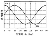
주위면을 다극(多極)으로 착자(着磁)한 원통 자석을 원통의 축을 중심으로 하여 회전시켰을 때, 상기 주위면으로부터 소정 거리(r1) 떨어진 위치에서의 원통 자석의 반경 방향의 자속(磁束) 밀도 및 주위 방향의 자속 밀도는, 각각 회전 각도에 대하여 대략 정현파형(正弦波狀)으로 변화한다. 이 때, 반경 방향의 자속 밀도의 진폭은, 회전 방향의 자속 밀도의 진폭에 비해 1 ~ 2배 정도 크게 된다.When a cylindrical magnet having a peripheral surface magnetized with a plurality of poles is rotated around the axis of the cylinder, a magnetic flux in a radial direction of the cylindrical magnet at a position (r 1 ) Flux density) and the magnetic flux density in the circumferential direction change in a substantially sinusoidal waveform with respect to the rotation angle, respectively. At this time, the amplitude of the magnetic flux density in the radial direction becomes 1 to 2 times larger than the amplitude of the magnetic flux density in the rotating direction.
상기 거리(r1) 떨어진 위치에 센서 디바이스(복수 개의 스핀 밸브형 거대 자기 저항 효과 소자를 사용한 자기 센서)를 배치하고, 반경 방향의 자속 밀도 및 회전 방향의 자속 밀도를 측정함으로써 회전 각도 검출 장치를 구성할 수 있다.A sensor device (a magnetic sensor using a plurality of spin valve type giant magnetoresistive elements) is disposed at a position apart from the distance r 1 and the magnetic flux density in the radial direction and the magnetic flux density in the rotational direction are measured, Can be configured.
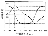
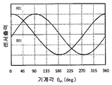
센서 디바이스는 자장의 강도는 아니고 자속의 방향을 검지하므로, 반경 방향의 자속 밀도의 진폭과 회전 방향의 자속 밀도의 진폭이 상이하면, 반경 방향으로 감자축(感磁軸)을 가지는 센서 디바이스로부터는 사다리꼴의 파형을 한 제1 출력 전압(Vx)을 얻을 수 있고, 회전 방향으로 감자축을 가지는 센서 디바이스로부터는 삼각파상의 파형을 한 제2 출력 전압(Vy)을 얻을 수 있다. 여기서, 직교하는 2개의 감자축을 1개의 기판에 집약한 센서 디바이스를 사용함으로써, 상기 제1 및 제2 출력 전압을 동시에 얻을 수 있다.If the amplitude of the magnetic flux density in the radial direction is different from the amplitude of the magnetic flux density in the rotational direction because the sensor device detects the direction of the magnetic flux instead of the intensity of the magnetic field, the sensor device having the magnetostrictive axis in the radial direction It is possible to obtain a first output voltage V x having a trapezoidal waveform and a second output voltage V y having a triangular waveform on the sensor device having the potato axis in the rotation direction. Here, the first and second output voltages can be obtained at the same time by using a sensor device in which two orthogonal potato axes are concentrated on one substrate.
또한, 자속 밀도가 어느 일정 범위 내이면, 반경 방향 및 회전 방향의 자속 밀도의 최대값에 의하지 않고, 그 출력 전압의 진폭은 대략 일정하게 된다. 즉, 상기 제1 및 제2 출력 전압은, 후술하는 바와 같이 자석의 회전각 θ mag에 대하여 각각 Vx = cosθ mag 및 Vy = sinθ mag로 되고, 이들 진폭은 대략 같게 된다(단 실제로 얻어지는 파형은 고조파(高調波)를 포함하므로, 파형은 각각 사다리꼴 및 삼각형상으로 된다). 이와 같이, 제1 및 제2 출력 전압은 파형이 상이하고, 자속 밀도의 진폭의 차이에도 불구하고 대략 같은 진폭의 출력 전압을 얻을 수 있으므로, 회전 각도의 측정 오차(각도 오차)가 생긴다.Further, if the magnetic flux density is within a certain range, the amplitude of the output voltage becomes substantially constant irrespective of the maximum value of the magnetic flux density in the radial direction and the rotational direction. That is, the first and second output voltages become V x = cos θ mag and V y = sin θ mag , respectively, with respect to the rotation angle θ mag of the magnet as will be described later, The resulting waveform includes harmonics, so that the waveforms are trapezoidal and triangular, respectively). As described above, the first and second output voltages have different waveforms, and an output voltage having substantially the same amplitude can be obtained despite the difference in amplitude of the magnetic flux density, resulting in a measurement error (angular error) of the rotation angle.
일본공개특허 제2006-023179호(특허 문헌 1)는, 자기(磁氣) 부재와, 상기 자기 부재의 자극 배열면과 대향하는 복수쌍의 벡터 검지형 자기 저항 효과 소자를 가지고, 상기 복수쌍의 벡터 검지형 자기 저항 효과 소자를, 상기 자기 부재에 의한 외부 자계에 대하여 감자면이 대략 평행하게, 또한 쌍을 이루는 상기 벡터 검지형 자기 저항 효과 소자끼리의 핀층 자화(磁化) 방향이 서로 대략 90도 어긋나도록 배치하는 동시에, 상기 자기 부재의 자극 배열 방향에 대하여는 동일 위치에 모든 상기 벡터 검지형 자기 저항 효과 소자를 배치한 자기식 위치 검출 장치를 개시하고 있고, 특허 문헌 1의 도 1a에 나타낸 자기 부재 및 벡터 검지형 자기 저항 효과 소자를 상대적으로 이동시킴으로써, 위상이 90도 어긋난 2상의 정현파형 출력을 얻는 것으로 기재하고 있다.Japanese Patent Application Laid-Open No. 2006-023179 (Patent Document 1) discloses a magnetic sensor comprising a magnetic member and a plurality of pairs of vector detection type magnetoresistance effect elements facing the magnetic pole arrangement surface of the magnetic member, The vector detection type magnetoresistance effect element is arranged so that the magnetization directions of the pinned layer magnetization directions of the pair of vector detection type magnetoresistance effect elements are substantially parallel to the external magnetic field by the magnetic member, And all of the vector detection type magnetoresistive elements are disposed at the same position with respect to the magnetic pole array direction of the magnetic member. In the magnetic position detection apparatus disclosed in
그러나, 일본공개특허 제2006-023179호(특허 문헌 1)에 기재된 바와 같이, 위상이 90도 어긋난 2상의 정현파형 출력을 얻을 수 있는 것은, 이동 방향과 자기 부재에 수직 방향의 자속 밀도 진폭비가 대략 1로 되는 경우(자기 부재의 착자 피치에 대하여 자극의 가로 방향 치수가 극단으로 긴 경우)이며, 실제는 상기 자속 밀도 진폭이 상이하므로, 자장 검출기로부터의 출력 전압은 고차의 고조파가 중첩된 사다리꼴 파형 및 삼각파상 파형으로 된다. 그 결과, 위치 검출에 오차가 생겨 정밀도 양호한 측정을 행할 수 없게 된다.However, as described in Japanese Patent Laid-Open Publication No. 2006-023179 (Patent Document 1), it is possible to obtain a two-phase sinusoidal output whose phase is shifted by 90 degrees because the magnetic flux density amplitude ratio in the moving direction and in the direction perpendicular to the magnetic member is approximately 1 (in the case where the lateral dimension of the magnetic pole is long relative to the magnetizing pitch of the magnetic member), and actually the magnetic flux density amplitude is different, the output voltage from the magnetic field detector is a trapezoidal waveform And a triangular wave waveform. As a result, an error occurs in the position detection, and accurate measurement can not be performed.
일본공개특허 제2006-194861호(특허 문헌 2)는, 자기 저항 효과 소자를 사용하여 회전 각도를 검출하는 경우에, 자기 저항 효과 소자로부터의 출력에 포함되어 있는 신호 사이의 위상 오차, 불균일 오차 등을, 다양한 파형 정형에 의해 저감시키는 방법을 개시하고 있다. 그러나, 평행 자장이 회전함으로써 생기는 자장에 원리적으로 포함되는 불균일성(외부 자장의 진폭비의 상위 등)에 의한 오차를 저감시키는 방법에 대해서는 개시되어 않다.Japanese Patent Application Laid-Open No. 2006-194861 (Patent Document 2) discloses a technique for detecting a rotation angle by using a magneto-resistive effect element, such as a phase error and a nonuniformity error between signals included in the output from the magneto- Is reduced by various waveform shaping. However, a method for reducing the error caused by nonuniformity (difference in amplitude ratio of the external magnetic field, etc.) principally included in the magnetic field generated by the rotation of the parallel magnetic field is not disclosed.
일본공개특허 제2006-023179호(특허 문헌 1) 및 일본공개특허 제2006-194861호(특허 문헌 2)는, 반경 방향의 자속 밀도의 진폭이 회전 방향의 자속 밀도의 진폭에 비해 크기 때문에, 반경 방향 및 회전 방향의 출력 전압의 파형이 상이하고, 그 결과 생기는 각도 오차에 대하여 기재에 되어 있지 않고, 그 시사조차도 없다. 이들 문헌에 기재된 기술에 있어서, 이동 방향의 자속 밀도 진폭과 자기 부재로부터 수직 방향의 자속 밀도 진폭을 동일하게 하기 위해서는, 자극의 가로 방향 치수를, 예를 들면, 자극 피치에 대하여 100배 정도로 할 필요가 있다. 그러나, 회전 각도 또는 이동 거리를 검출하기 위해 그와 같은 큰 자기 부재를 설치하는 것은 현실적이지 않다.Since the amplitude of the magnetic flux density in the radial direction is larger than the amplitude of the magnetic flux density in the rotational direction, as disclosed in Japanese Patent Laid-Open Nos. 2006-023179 and 2006-194861 (Patent Literature 2) The waveforms of the output voltages in the direction and the rotational direction are different from each other, and the resulting angular error is not described, and there is no such indication. In the technique described in these documents, in order to make the amplitude of the magnetic flux density in the moving direction equal to the amplitude of the magnetic flux density in the vertical direction from the magnetic member, it is necessary to make the lateral dimension of the magnetic pole to be about 100 times, for example, . However, it is not realistic to install such a large magnetic member for detecting the rotation angle or the moving distance.
이상과 같이, 자속의 방향을 검출할 수 있는 센서 디바이스를 사용한 경우, 얻어지는 2개의 출력 전압을 그대로 역정접(逆正接) 연산하고 자석 회전자의 전기각(電氣角)이나 회전각을 구하려면, 각도 오차가 큰 회전 각도 검출 장치로 밖에 할 수 없다는 문제가 있었다.As described above, when a sensor device capable of detecting the direction of the magnetic flux is used, in order to obtain the electric angle (electric angle) and the rotation angle of the magnet rotor without calculating the two output voltages as they are, There has been a problem in that it can only be performed by a rotation angle detecting device having a large angular error.
따라서, 본 발명의 목적은, 높은 정밀도로 회전 각도를 검출할 수 있는 회전 각도 검출 장치, 및 이것을 구비한 회전기를 제공하는 것에 있다.Accordingly, it is an object of the present invention to provide a rotation angle detecting device capable of detecting a rotation angle with high precision, and a rotating machine having the same.
상기 목적을 감안하여 예의 검토의 결과, 본 발명자 등은, 자속의 방향을 검지하는 센서 디바이스를 사용한 회전 각도 검출 장치에 있어서, 센서 디바이스로부터 얻어진 반경 방향 및 회전 방향의 2개의 출력 전압(또는 출력 전압 파형) 중 적어도 한쪽에 수정(修正) 계수를 곱하거나(또는 나누어), 이들 수정한 2개의 출력 전압(또는 출력 전압 파형)의 최대값의 비가, 센서 디바이스를 배치한 위치에서의 반경 방향 및 회전 방향의 자속 밀도의 최대값의 비 K'와 동등하게 되도록 한 후, 역정접 연산함으로써 각도 오차가 현저하게 작아지는 것을 발견하고, 본 발명에 이르렀다.As a result of intensive studies in view of the above object, the present inventors have found that, in a rotational angle detecting apparatus using a sensor device for detecting the direction of magnetic flux, two output voltages in the radial direction and rotational direction (Or divided), and the ratio of the maximum value of the two output voltages (or the output voltage waveform) is calculated in the radial direction and the rotational direction at the position where the sensor device is disposed Direction of the magnetic flux density of the magnetic flux density of the magnetic flux density of the magnetic flux density of the magnetic flux density of the magnetic flux density in the direction of the magnetic flux density.
본 발명의 회전 각도 검출 장치는, 도 27에 나타낸 바와 같이, 얻어진 출력 전압 파형 중 적어도 한쪽의 진폭을 확대시켜, 2개의 출력 전압 파형의 최대값의 비를 대응하는 2방향의 자속 밀도의 최대값의 비와 동등하게 되도록 조절하고 나서 회전각이나 기계각을 구하는 것이다. 이 조절 수단으로서는, 한쪽만을 확대시키는 방법, 한쪽만을 축소시키는 방법, 또는 양쪽에 소정 계수를 주는 방법 중 어느 하나의 수단에 의해서도 되고, 결과적으로 2개의 출력 전압 파형의 최대값의 비가, 상기한 비 K'와 동등하게 되도록 수정하면 된다. 이하, 한쪽에 수정 계수를 곱하는 것을 중심으로 설명하지만, 본 발명은 이에 한정되지 않고, 다른 쪽을 나누어 수정해도 되고, 양쪽에 상이한 소정 계수를 걸어 수정해도 된다.27, the amplitude of at least one of the obtained output voltage waveforms is enlarged and the ratio of the maximum value of the two output voltage waveforms is set to the maximum value of the corresponding two magnetic flux densities And then the rotation angle or the mechanical angle is obtained. As the adjusting means, either of a method of enlarging only one side, a method of reducing only one side, or a method of applying a predetermined coefficient to both sides may be used. As a result, the ratio of the maximum value of the two output voltage waveforms K '. Hereinafter, the multiplication of the correction coefficient on one side will be mainly described, but the present invention is not limited to this, and the other may be modified or modified by applying a predetermined coefficient to both sides.
즉, 본 발명의 회전 각도 검출 장치는, That is, in the rotation angle detecting device of the present invention,
2N극 자석을 가지는 자석 회전자(N은 자연수임)와, 상기 자석 회전자로부터의 자속의 방향을 검지하는 센서 디바이스를 사용하여 회전 각도를 검출하는 회전 각도 검출 장치로서, 1. A rotation angle detecting device for detecting a rotation angle by using a magnet rotor (N is a natural number) having a 2N pole magnet and a sensor device for detecting a direction of a magnetic flux from the magnet rotor,
상기 센서 디바이스에 의해 얻어지는 반경 방향 및 회전 방향의 2개의 출력 전압값 중 적어도 한쪽에 수정 계수를 곱하고, 수정된 2개의 출력 전압값으로부터 회전 각도를 산출함으로써, 회전 각도의 검출 정밀도를 높이는 것을 특징으로 한다.Characterized in that at least one of the two output voltage values in the radial direction and the rotational direction obtained by the sensor device is multiplied by a correction coefficient and the rotation angle is calculated from the two corrected output voltage values, do.
본 발명의 다른 회전 각도 검출 장치는, Another rotation angle detecting device of the present invention includes:
2N극 자석을 가지는 자석 회전자(N은 자연수임)와, 상기 자석 회전자로부터의 자속의 방향을 검지하는 센서 디바이스를 구비하는 회전 각도 검출 장치로서, 1. A rotation angle detecting device comprising a magnet rotor (N is a natural number) having a 2N pole magnet and a sensor device for detecting the direction of a magnetic flux from the magnet rotor,
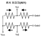
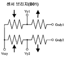
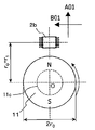
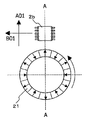
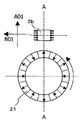
상기 센서 디바이스는, 복수 개의 스핀 밸브형 거대 자기 저항 효과 소자(고정층과 자유층을 가지고, 고정층 자화 방향이 고정되어 있고, 자유층 자화 방향이 자속의 방향을 따라 회전하는 자기 저항 소자)로 구성된 감자면을 가지고, 서로 고정층 자화 방향이 직교하는 센서 브리지(A01)와 센서 브리지(B01)를 내장하고, The sensor device includes a plurality of spin valve type giant magnetoresistive elements (a magnetoresistive element having a pinned layer and a free layer fixed in a fixed layer magnetization direction and a free layer magnetization direction rotating in the direction of the magnetic flux) And a sensor bridge A01 and a sensor bridge B01 in which the fixed layer magnetization directions are orthogonal to each other,
상기 센서 브리지(A01) 및 센서 브리지(B01)는, 각각 상기 스핀 밸브형 거대 자기 저항 효과 소자의 브리지 회로이며, The sensor bridge A01 and the sensor bridge B01 are bridge circuits of the spin valve type giant magnetoresistive element,
상기 브리지 회로는, 각각 전기적으로 인접하는 변의 스핀 밸브형 거대 자기 저항 효과 소자의 고정층 자화 방향이 반평행이며, In the bridge circuit, magnetization directions of fixed layer magnetization directions of the spin valve type giant magnetoresistive elements on the electrically adjacent sides are antiparallel,
상기 센서 브리지(A01) 및 센서 브리지(B01)의 각각에 전압을 인가함으로써, 상기 고정층 자화 방향과 상기 자유층 자화 방향이 이루는 각도에 따른 출력 전압을 얻고, An output voltage according to an angle formed by the fixed layer magnetization direction and the free layer magnetization direction is obtained by applying a voltage to each of the sensor bridge A01 and the sensor bridge B01,
상기 출력 전압 중 적어도 한쪽에 수정 계수를 곱하여 얻어진 2개의 출력을 기초로 하여 각도 신호를 얻는 것을 특징으로 한다.And an angle signal is obtained based on two outputs obtained by multiplying at least one of the output voltages by a correction coefficient.
상기 센서 디바이스는, 복수 개의 스핀 밸브형 거대 자기 저항 효과 소자(고정층과 자유층을 가지고, 고정층 자화 방향이 직교하는 2방향으로 고정되어 있고, 자유층 자화 방향이 자속의 방향을 따라 회전하는 자기 저항 소자)로 구성된 감자면을 가지고, Wherein the sensor device comprises a plurality of spin valve type giant magnetoresistive elements having a pinned layer and a free layer and fixed in two directions in which the pinned layer magnetization directions are orthogonal to each other and in which the free layer magnetization direction rotates along the direction of the magnetic flux Element,
상기 수정 계수는, 상기 센서 디바이스를 설치한 위치에서의 반경 방향의 자속 밀도의 최대값과 회전 방향의 자속 밀도의 최대값과의 비를 반영한 값인 것이 바람직하다.The correction factor is preferably a value reflecting the ratio between the maximum value of the magnetic flux density in the radial direction and the maximum value of the magnetic flux density in the rotational direction at the position where the sensor device is installed.
상기 센서 디바이스를 설치한 위치에서의, 반경 방향의 자속 밀도의 진폭 B⊥과 회전 방향의 자속 밀도의 진폭 B//와의 비를 B⊥/B// = K'로 한 경우, 상기 수정 후의 반경 방향의 출력 전압값의 피크값과 회전 방향의 출력 전압값의 피크값과의 비 K는, K = K'±0.3N의 범위인 것이 바람직하다.In a position to install the sensor device, when the ratio of the amplitude B // of the amplitude B ⊥ magnetic flux density in the rotational direction of the magnetic flux density in the radial direction in B ⊥ / B // = K ' , the radius after the modified The ratio K of the peak value of the output voltage value in the direction of rotation to the peak value of the output voltage value in the rotation direction is preferably in the range of K = K '± 0.3N.
본 발명의 또 다른 회전 각도 검출 장치는, In another rotation angle detecting device of the present invention,
2N극 자석을 가지는 자석 회전자(N은 자연수임)와, 상기 자석 회전자로부터의 자속의 방향을 검지하는 센서 디바이스를 사용하여 회전 각도를 검출하는 회전 각도 검출 장치로서, 1. A rotation angle detecting device for detecting a rotation angle by using a magnet rotor (N is a natural number) having a 2N pole magnet and a sensor device for detecting a direction of a magnetic flux from the magnet rotor,
상기 센서 디바이스에 의해 얻어지는 반경 방향 및 회전 방향의 2개의 출력 전압값의 출력 파형 중 적어도 한쪽의 진폭값에 수정 계수를 곱하고, 수정된 2개의 출력 파형으로부터 회전 각도를 산출함으로써, 회전 각도의 검출 정밀도를 높이는 것을 특징으로 한다.At least one of amplitude values of two output voltage values in the radial direction and the rotational direction obtained by the sensor device is multiplied by a correction coefficient and the rotation angle is calculated from the two modified output waveforms, .
상기 센서 디바이스는, 복수 개의 스핀 밸브형 거대 자기 저항 효과 소자(고정층과 자유층을 가지고, 고정층 자화 방향이 직교하는 2방향으로 고정되어 있고, 자유층 자화 방향이 자속의 방향을 따라 회전하는 자기 저항 소자)로 구성된 감자면을 가지고, Wherein the sensor device comprises a plurality of spin valve type giant magnetoresistive elements having a pinned layer and a free layer and fixed in two directions in which the pinned layer magnetization directions are orthogonal to each other and in which the free layer magnetization direction rotates along the direction of the magnetic flux Element,
상기 수정 계수는, 상기 센서 디바이스를 설치한 위치에서 반경 방향 및 회전 방향의 2방향의 자속 밀도의 파형을 취했을 때의, 각각의 최대 진폭의 비를 반영한 값인 것이 바람직하다.It is preferable that the correction factor is a value reflecting the ratio of the respective maximum amplitudes when the waveform of the magnetic flux density in the two directions of the radial direction and the rotational direction is taken at the position where the sensor device is installed.
상기 센서 디바이스를 설치한 위치에서의, 반경 방향의 자속 밀도의 진폭 B⊥과 회전 방향의 자속 밀도의 진폭 B//와의 비를 B⊥/B// = K'로 한 경우, 상기 수정 후의 반경 방향의 출력 파형의 피크값과 회전 방향의 출력 파형의 피크값과의 비 K는, K = K'±0.3N의 범위의 값인 것이 바람직하다.In a position to install the sensor device, when the ratio of the amplitude B // of the amplitude B ⊥ magnetic flux density in the rotational direction of the magnetic flux density in the radial direction in B ⊥ / B // = K ' , the radius after the modified The ratio K between the peak value of the output waveform in the direction of rotation and the peak value of the output waveform in the rotation direction is preferably a value in the range of K = K '± 0.3N.
본 발명의 또 다른 회전 각도 검출 장치는, In another rotation angle detecting device of the present invention,
2N극 자석을 가지는 자석 회전자(N은 자연수임)와, 상기 자석 회전자로부터의 자속의 방향을 검지하는 센서 디바이스를 구비하는 회전 각도 검출 장치로서, 1. A rotation angle detecting device comprising a magnet rotor (N is a natural number) having a 2N pole magnet and a sensor device for detecting the direction of a magnetic flux from the magnet rotor,
상기 센서 디바이스는, 복수 개의 스핀 밸브형 거대 자기 저항 효과 소자(고정층과 자유층을 가지고, 고정층 자화 방향이 고정되어 있고, 자유층 자화 방향이 자속의 방향을 따라 회전하는 자기 저항 소자)로 구성된 감자면을 가지고, 서로 고정층 자화 방향이 직교하는 센서 브리지(A01)와 센서 브리지(B01)를 내장하고, The sensor device includes a plurality of spin valve type giant magnetoresistive elements (a magnetoresistive element having a pinned layer and a free layer fixed in a fixed layer magnetization direction and a free layer magnetization direction rotating in the direction of the magnetic flux) And a sensor bridge A01 and a sensor bridge B01 in which the fixed layer magnetization directions are orthogonal to each other,
상기 센서 브리지(A01) 및 센서 브리지(B01)는, 각각 상기 스핀 밸브형 거대 자기 저항 효과 소자의 브리지 회로이며, The sensor bridge A01 and the sensor bridge B01 are bridge circuits of the spin valve type giant magnetoresistive element,
상기 브리지 회로는, 각각 전기적으로 인접하는 변의 스핀 밸브형 거대 자기 저항 효과 소자의 고정층 자화 방향이 반평행이며, In the bridge circuit, magnetization directions of fixed layer magnetization directions of the spin valve type giant magnetoresistive elements on the electrically adjacent sides are antiparallel,
상기 센서 브리지(A01) 및 센서 브리지(B01)의 각각에 전압을 인가함으로써, 상기 고정층 자화 방향과 상기 자유층 자화 방향이 이루는 각도에 따른 출력 전압(Vx, Vy)을 얻고, (V x , V y ) according to an angle formed by the fixed layer magnetization direction and the free layer magnetization direction by applying a voltage to each of the sensor bridge A01 and the sensor bridge B01,
상기 출력 전압 중 적어도 한쪽에 수정 계수를 곱하여 각도 신호를 얻는 것을 특징으로 한다. And an angle signal is obtained by multiplying at least one of the output voltages by a correction coefficient.
[단, Vx는 상기 자석 회전자의 반경 방향으로 고정층 자화 방향을 향한 센서 브리지(A01)의 출력 전압, [However, V x is the output voltage of the sensor bridge (A01) towards the fixing layer the magnetization direction in a radial direction of the magnet rotor,
Vy는 상기 자석 회전자의 회전 방향으로 고정층 자화 방향을 향한 센서 브리지(B01)의 출력 전압이며, V y is the output voltage of the sensor bridge B 01 toward the fixed layer magnetization direction in the rotating direction of the magnet rotor,
상기 수정 계수는, Vx 및 Vy의 각각에 대하여, 전기각 1주기를 푸리에(fourier) 전개한 하기의 식(1-1) 및 식(1-2)에 있어서의 a1, a3, b1 및 b3의 수치를 기초로 산출한 값이다. The correction coefficient is a value obtained by multiplying each of V x and V y by a 1 , a 3 , and a 1 in the following equations (1-1) and (1-2) in which one electrical period is fourier- b 1, and b 3 .

상기 수정 계수로서 k를 사용하는 것이 바람직하다. It is preferable to use k as the correction coefficient.
[단, 수정 계수 k는, K = k'±0.3N{N은 자석 회전자의 극대수(極對數)이며, k'는 상기 식(1-1) 및 식(1-2)에 있어서의 a1, a3, b1 및 b3의 수치에 의해, 식(2): ![]()
![]()
상기 센서 디바이스는, 반경 방향의 자속 밀도의 최대값과 회전 방향의 자속 밀도의 최대값이 상이한 값을 나타내는 위치에 설치되어 있는 것이 바람직하다.It is preferable that the sensor device is installed at a position where a maximum value of the magnetic flux density in the radial direction and a maximum value of the magnetic flux density in the rotating direction are different from each other.
상기 센서 디바이스의 감자면의 중심은, 상기 자석 회전자의 축방향 두께 중심점을 통과하고 또한 회전축에 수직인 평면 상에 위치하는 것이 바람직하다.The center of the magnetosensitive surface of the sensor device is preferably located on a plane that passes through the axial center thickness point of the magnet rotor and is perpendicular to the rotation axis.
본 발명의 회전기는, 상기 어느 하나의 회전 각도 검출 장치를 탑재하는 것을 특징으로 한다.The rotating machine of the present invention is characterized in that any one of the above-described rotation angle detecting devices is mounted.
본 발명의 회전 각도 검출 방법은, In the rotation angle detection method of the present invention,
2N극 자석을 가지는 자석 회전자(N은 자연수임)의 회전 각도를 검출하는 회전 각도 검출 방법으로서, A rotation angle detecting method for detecting a rotation angle of a magnet rotor (N is a natural number) having a 2N pole magnet,
센서 디바이스에 의해 상기 자석 회전자의 반경 방향 및 회전 방향의 자속의 주기 변동을 출력 전압(Vx, Vy)으로서 측정하고, The sensor device measures the periodic variation of the magnetic flux in the radial direction and the rotational direction of the magnet rotor as the output voltages (V x , V y )
상기 출력 전압 중 적어도 한쪽에 수정 계수를 곱하여, 상기 자석 회전자의 회전 각도 θ meas를 구하는 것을 특징으로 한다.And at least one of the output voltages is multiplied by a correction coefficient to obtain a rotation angle ? Meas of the magnet rotor.
상기 센서 디바이스를 설치한 위치에서의, 반경 방향의 자속 밀도의 진폭 B⊥과 회전 방향의 자속 밀도의 진폭 B//와의 비를 B⊥/B// = K'로 한 경우, 상기 수정 후의 반경 방향의 출력 전압값의 피크값과 회전 방향의 출력 전압값의 피크값과의 비 K는, K = K'±0.3N의 범위인 것이 바람직하다.In a position to install the sensor device, when the ratio of the amplitude B // of the amplitude B ⊥ magnetic flux density in the rotational direction of the magnetic flux density in the radial direction in B ⊥ / B // = K ' , the radius after the modified The ratio K of the peak value of the output voltage value in the direction of rotation to the peak value of the output voltage value in the rotation direction is preferably in the range of K = K '± 0.3N.
상기 수정 계수로서 k값을 사용하여, 상기 자석 회전자의 회전 각도 θ meas를 식(3) 또는 식(4)로부터 구하는 것이 바람직하다. It is preferable that the rotation angle ? Meas of the magnet rotor is obtained from the formula (3) or (4) using the k value as the correction coefficient.
![]()
![]()
![]()
![]()
상기 수정 계수 k값은, 센서 디바이스를 설치한 위치에서, 반경 방향의 자속 밀도의 진폭 B⊥와 회전 방향의 자속 밀도의 진폭 B//를 측정하고, 그 진폭비 B⊥/B// = K'를 기초로 산출하는 것이 바람직하다.The correction factor k values are, in one installation the sensor device position, and measures the amplitude B // of the amplitude B of the magnetic flux density ⊥ and the direction of rotation of the magnetic flux density in the radial direction, the amplitude ratio B ⊥ / B // = K ' Is calculated on the basis of the following equation.
상기 수정 계수 k값은, 상기 출력 전압(Vx, Vy)의 각각에 대하여, 전기각 1주기를 푸리에 전개한 식(5-1) 및 식(5-2)에 있어서의 a1, a3, b1 및 b3의 수치를 기초로 산출한 값으로 하는 것이 바람직하다. The correction coefficient k is a value obtained by multiplying each of the output voltages V x and V y by a 1 , a (5-2) in equations (5-1) and (5-2) 3 , b 1, and b 3 , respectively.

상기 수정 계수 k는, 상기 a1, a3, b1 및 b3의 수치를 사용하여 하기 식(6)으로부터 구한 k'를 기초로 산출하는 것이 바람직하다. It is preferable that the correction coefficient k is calculated on the basis of k 'obtained from the following equation (6) using the values of a 1 , a 3 , b 1 and b 3 .
![]()
![]()
상기 수정 계수 k로서 K = k'±0.3N{N은 자석 회전자의 극대수이며, k'는 상기 식(6)에서 구해지는 값임}의 범위의 값을 사용하는 것이 바람직하다.It is preferable to use a value in the range of K = k '± 0.3N (where N is the maximum number of the magnet rotator and k' is the value obtained in the above formula (6)) as the correction coefficient k.
상기 반경 방향의 자속 밀도의 최대값과 회전 방향의 자속 밀도의 최대값은, 자속의 방향을 측정하는 위치(센서 디바이스를 설치한 위치)에 홀 소자를 두고, 센서 디바이스에 의해 측정하는 2방향(반경 방향 및 회전 방향)에 대하여 각각 측정함으로써 구할 수 있다.The maximum value of the magnetic flux density in the radial direction and the maximum value of the magnetic flux density in the rotational direction are set in such a manner that a Hall element is placed at a position for measuring the direction of the magnetic flux The radial direction and the rotational direction).
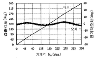
N극쌍으로 착자된 자석 회전자와, 스핀 밸브형 거대 자기 저항 효과 소자를 가지는 센서 디바이스를 사용한 회전 각도 검출 장치에 의해, 자석 회전자를 회전시키고, 자석 회전자의 회전 각도에 대응하는 출력 전압을 측정하면, 감자축이 반경 방향인 센서 브리지에서는 사다리꼴파에 가까운 출력 전압(제1 출력 전압)을 얻을 수 있고, 감자축이 회전 방향인 센서 브리지에서는 삼각파에 가까운 출력 전압(제2 출력 전압)을 얻을 수 있다. 이 때, 상기 제2 출력 전압을, 자속 밀도 진폭비 K'와 대략 같은 수정 계수 k로 증폭함으로써 고정밀도로 회전 각도를 검출할 수 있다.The magnet rotor is rotated by a magnet rotor rotated by N poles and a rotation angle detector using a sensor device having a spin valve type magneto-resistive effect element, and an output voltage corresponding to the rotation angle of the magnet rotor As a result of measurement, it is possible to obtain an output voltage (first output voltage) close to a trapezoidal wave in a sensor bridge having a potentiometer axis in the radial direction and an output voltage (second output voltage) close to a triangular wave in a sensor bridge in which the potentiometer axis is a rotational direction Can be obtained. At this time, the rotation angle can be detected with high accuracy by amplifying the second output voltage to a correction coefficient k approximately equal to the magnetic flux density amplitude ratio K '.
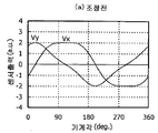
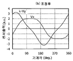
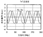
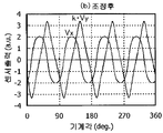
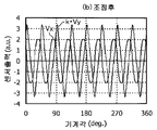
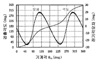
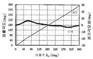
출력 전압 중, 교류 전력이 작은 쪽의 출력 전압에 수정 계수 k를 곱하는 것이 바람직하다. 일반적으로, 상기 제1 출력 전압에 비해 제2 출력 전압의 교류 전력이 작으므로, 제2 출력 전압에 k를 곱하는 것이 바람직하다. 즉, 도 7a에 나타낸 바와 같이, 기계각(가로축)과 센서 출력의 파형으로 에워싸인 면적이 작은 쪽의 출력 전압에 수정 계수 k를 곱하여, 도 7b에 나타낸 조정한 센서 출력을 사용하여 회전각을 산출한다. 또는, 기계각(가로축)과 센서 출력의 파형으로 에워싸인 면적이 큰 쪽의 출력 전압에 수정 계수 k를 나누어 회전각을 산출해도 된다. 또한, 곱함으로써 수정 계수 k로 되는 2개의 수치를 산출하고, 그 각각을 양쪽의 파형에 곱해도 된다. 그리고, 상기 식(2)에서 산출한 k'를 수정 계수 k로서 사용하는 경우에는, 수정 계수 k는 감자축이 회전 방향을 향하고 있는 센서 브리지에서의 출력 전압(제2 출력 전압)에 곱한다.It is preferable to multiply the output voltage having the smaller AC power among the output voltages by the correction coefficient k. Generally, since the AC power of the second output voltage is smaller than the first output voltage, it is preferable to multiply the second output voltage by k. That is, as shown in Fig. 7A, the output voltage having the smaller area surrounded by the machine angle (abscissa) and the waveform of the sensor output is multiplied by the correction coefficient k, and the rotation angle is calculated using the adjusted sensor output shown in Fig. . Alternatively, the rotational angle may be calculated by dividing the correction coefficient k by the output voltage of the larger area enclosed by the machine angle (transverse axis) and the waveform of the sensor output. Further, by multiplying two numerical values having a correction coefficient k, it is also possible to multiply each of the two numerical values by the two numerical values. When k 'calculated in the above equation (2) is used as the correction coefficient k, the correction coefficient k is multiplied by the output voltage (second output voltage) in the sensor bridge in which the axis of the potato is pointing in the rotation direction.
상기 자석 회전자는, 2극쌍 이상의 다극 착자를 실시한 자석 회전자인 것이 바람직하다. 1극쌍은 1개의 N극 및 그것과 인접하는 2개의 S극에 상당한다. 예를 들면, 12극으로 착자되어 있으면 6극쌍의 자석 회전자이다. 센서 디바이스 중에는 센서 브리지가 2개 있고, 센서 브리지끼리는 엘리먼트의 고정층 자화 방향이 직교한다.It is preferable that the magnet rotor is a magnet rotor which is subjected to multipolar magnetization of two pole pairs or more. A single pole pair corresponds to one N pole and two S poles adjacent to it. For example, if it is magnetized to 12 poles, it is a 6 pole pair magnet rotor. Among the sensor devices, there are two sensor bridges, and the fixed bridge magnetization directions of the elements are orthogonal to each other between the sensor bridges.
센서 디바이스는, 자석 회전자가 회전했을 때, 엘리먼트인 스핀 밸브형 거대 자기 저항 효과 소자의 자유층의 자화 방향이 회전하도록, 자석 회전자의 근방에 설치한다. 1개의 센서 디바이스 내의 센서 브리지는 엘리먼트끼리가 90deg. 경사지게 배치되어 있으므로, 센서 디바이스끼리를 90deg. 위상차를 가지도록 배치하지 않아도, 회전 각도를 정확하게 측정할 수 있다.The sensor device is provided in the vicinity of the magnet rotor so that the magnetization direction of the free layer of the spin valve type giant magnetoresistive element, which is an element, rotates when the magnet rotor rotates. The sensor bridge in one sensor device has 90 deg. Since the sensors are arranged in an inclined manner, the sensor devices are arranged at 90 deg. The rotation angle can be accurately measured even if it is not arranged so as to have a phase difference.
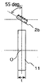
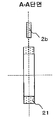
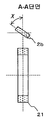
상기 자석의 축방향 두께(t)는, 회전축 방향에서의 자석의 치수에 상당한다. 상기 센서 디바이스의 중심은, 스핀 밸브형 거대 자기 저항 효과 소자의 중심, 또는 스핀 밸브형 거대 자기 저항 효과 소자가 복수 개 있는 경우에는 이들로부터 대략 등거리에 있는 중심점으로 한다. 스핀 밸브형 거대 자기 저항 효과 소자의 두께는 자석 회전자보다 충분히 얇기 때문에, 상기 중심점은 스핀 밸브형 거대 자기 저항 효과 소자를 형성하는 기판 상에 있는 것으로서 지장을 주지 않는다. 즉, 상기 센서 디바이스의 중심은 감자면 상에 있다고 할 수 있다. 2개의 감자축은 직교 관계에 있고, 상기 감자면 내에 있거나 또는 상기 감자면과 평행이다.The axial thickness t of the magnet corresponds to the dimension of the magnet in the direction of the rotation axis. The center of the sensor device is a center of a spin-valve type giant magnetoresistive element or a center point of the giant magnetoresistive element when the plurality of giant magnetoresistive elements are spin-valve type. Since the thickness of the spin valve type giant magnetoresistance effect element is sufficiently thinner than that of the magnet rotor, the center point is on the substrate on which the spin valve type giant magnetoresistive element is formed, so that it does not hinder it. That is, the center of the sensor device can be said to be on the potato surface. The two potato axes are in an orthogonal relationship, and are either within the potato plane or parallel to the potato plane.
본원 명세서에 있어서, 센서 브리지는 4개의 엘리먼트(스핀 밸브형 거대 자기 저항 효과 소자)를 전기 회로적인 브리지에 조립한 것을 가리킨다(4개의 엘리먼트를 포함하는 면이 감자면으로 된다). 또한, 2개의 센서 브리지를 탑재한 것을 센서 디바이스라고 한다. 자석 회전자와 센서 디바이스를 대향시키는 구성을 회전 각도 검출 장치라고 한다. 회전 각도 검출 장치에 장착할 수 있도록 복수 개의 센서 디바이스를 조합한 단위를 모듈이라고 한다.In the present specification, the sensor bridge indicates that four elements (spin valve type giant magnetoresistance effect element) are assembled into an electric circuit bridge (the surface including four elements is a potentiometer surface). In addition, a device having two sensor bridges is referred to as a sensor device. A configuration for opposing the magnet rotor and the sensor device is referred to as a rotation angle detecting device. A unit in which a plurality of sensor devices are combined so as to be mounted on the rotation angle detecting device is referred to as a module.
본 발명의 회전 각도 검출 장치에 의해, 각도 오차를 저감할 수 있다. The angular error can be reduced by the rotation angle detecting device of the present invention.
본 발명의 회전 각도 검출 방법에 의해, 센서 디바이스의 위치에 관계없이 각도 오차를 저감할 수 있으므로, 자속 밀도가 가장 큰 위치에 센서 디바이스를 설치할 수 있어 자석의 체적을 작게 할 수 있다. 그 결과, 회전 각도 검출 장치의 점유 체적을 작게 하는 것이 가능하게 된다.According to the rotation angle detecting method of the present invention, since the angular error can be reduced regardless of the position of the sensor device, the sensor device can be installed at the position where the magnetic flux density is the largest, and the volume of the magnet can be reduced. As a result, it becomes possible to reduce the occupied volume of the rotation angle detecting device.
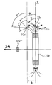
도 1a는 본 발명의 회전 각도 검출 장치의 일례를 나타낸 모식 정면도이다.
도 1b는 본 발명의 회전 각도 검출 장치의 일례를 나타낸 모식 측면도이며, 일점 쇄선보다 아래쪽은 자석 회전자를 단면(斷面)으로 나타낸 부분 단면도이다.
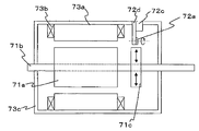
도 2a는 본 발명의 회전 각도 검출 장치에 사용하는 센서 디바이스의 일례를 나타낸 모식도이다.
도 2b는 도 2a의 센서 디바이스에 있어서의 고정층 자화 방향을 자석 회전자의 반경 방향으로 하는 엘리먼트와 단자와의 접속을 나타낸 브리지 회로도이다.
도 2c는 도 2a의 센서 디바이스에 있어서의 고정층 자화 방향을 자석 회전자의 회전 방향으로 하는 엘리먼트와 단자와의 접속을 나타낸 브리지 회로도이다.
도 3은 수정 계수 k의 산출 방법의 일례를 나타낸 개념도이다.
도 4는 회전 각도 검출 장치의 일례를 나타낸 개념도이다.
도 5는 회전 각도 검출 장치의 다른 일례를 나타낸 개념도이다.
도 6은 회전 각도 검출 장치의 또 다른 일례를 나타낸 개념도이다.
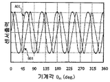
도 7a는 실시예 1의 회전 각도 검출 장치의 전압 조정 전의 센서 출력을 나타낸 그래프이다.
도 7b는 실시예 1의 회전 각도 검출 장치의 전압 조정 후의 센서 출력을 나타낸 그래프이다.
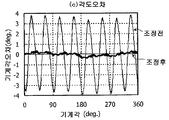
도 7c는 실시예 1의 회전 각도 검출 장치의 전압 조정 전 및 조정 후의 각도 오차를 나타낸 그래프이다.
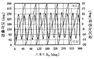
도 8a는 실시예 2의 회전 각도 검출 장치의 전압 조정 전의 센서 출력을 나타낸 그래프이다.
도 8b는 실시예 2의 회전 각도 검출 장치의 전압 조정 후의 센서 출력을 나타낸 그래프이다.
도 8c는 실시예 2의 회전 각도 검출 장치의 전압 조정 전 및 조정 후의 각도 오차를 나타낸 그래프이다.
도 9a는 실시예 3의 회전 각도 검출 장치의 전압 조정 전의 센서 출력을 나타낸 그래프이다.
도 9b는 실시예 3의 회전 각도 검출 장치의 전압 조정 후의 센서 출력을 나타낸 그래프이다.
도 9c는 실시예 3의 회전 각도 검출 장치의 전압 조정 전 및 조정 후의 각도 오차를 나타낸 그래프이다.
도 10은 수정 계수 k가 변화되었을 때의 기계각 오차를 나타낸 그래프이다.
도 11은 수정 계수 k가 변화되었을 때의 전기각 오차를 나타낸 그래프이다.
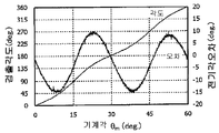
도 12는 x축 방향(회전축과 수직인 방향)으로 센서를 이동했을 때의 자석 반경 방향의 자속 밀도 B⊥, 자석 회전 방향의 자속 밀도 B//, 및 자속 밀도 진폭비 K'를 나타낸 그래프이다.
도 13은 z축 방향(회전축 방향)으로 센서를 이동했을 때의 자석 반경 방향의 자속 밀도 B⊥, 자석 회전 방향의 자속 밀도 B//, 및 자속 밀도 진폭비 K'를 나타낸 그래프이다.
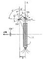
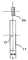
도 14a는 1극쌍 자석의 자속과 센서 디바이스와의 위치 관계를 나타낸 모식도이다.
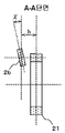
도 14b는 도 14a의 A-A 단면도이다.
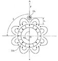
도 14c는 1극쌍 자석의 자속과 센서 디바이스와의 다양한 위치 관계를 나타낸 모식도이다.
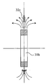
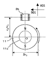
도 15a는 4극쌍 자석의 자속과 센서 디바이스와의 위치 관계를 나타낸 모식도이다.
도 15b는 도 15a의 A-A 단면도이다.
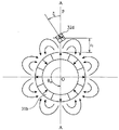
도 15c는 4극쌍 자석의 자속과 센서 디바이스와의 위치 관계를 나타낸 모식도이다.
도 15d는 4극쌍 자석의 자속과 센서 디바이스와의 다양한 위치 관계를 나타낸 모식도이다.
도 16은 본 발명의 회전 각도 검출 장치를 적용한 회전기의 일례를 나타낸 모식 단면도이다.
도 17a는 비교예 1의 회전 각도 검출 장치를 나타낸 모식 정면도이다.
도 17b는 비교예 1의 회전 각도 검출 장치를 나타낸 모식 측면도이다.
도 17c는 비교예 1의 회전 각도 검출 장치의 센서 출력을 나타낸 그래프이다.
도 17d는 비교예 1의 회전 각도 검출 장치의 검출 각도 및 오차를 나타낸 그래프이다.
도 18a는 참고예 1의 회전 각도 검출 장치를 나타낸 모식 정면도이다.
도 18b는 참고예 1의 회전 각도 검출 장치를 나타낸 모식 측면도이다.
도 18c는 참고예 1의 회전 각도 검출 장치의 센서 출력을 나타낸 그래프이다.
도 18d는 참고예 1의 회전 각도 검출 장치의 검출 각도 및 오차를 나타낸 그래프이다.
도 19a는 참고예 2의 회전 각도 검출 장치를 나타낸 모식 정면도이다.
도 19b는 참고예 2의 회전 각도 검출 장치를 나타낸 모식 측면도이다.
도 19c는 참고예 2의 회전 각도 검출 장치의 센서 출력을 나타낸 그래프이다.
도 19d는 참고예 2의 회전 각도 검출 장치의 검출 각도 및 오차를 나타낸 그래프이다.
도 20a는 비교예 2의 회전 각도 검출 장치를 나타낸 모식 정면도이다.
도 20b는 도 20a의 A-A 단면도이다.
도 20c는 비교예 2의 회전 각도 검출 장치의 센서 출력을 나타낸 그래프이다.
도 20d는 비교예 2의 회전 각도 검출 장치의 검출 각도 및 오차를 나타낸 그래프이다.
도 20e는 비교예 2의 회전 각도 검출 장치의 검출 각도 및 오차를 확대하여 나타낸 그래프이다.
도 21a는 참고예 3의 회전 각도 검출 장치를 나타낸 모식 정면도이다.
도 21b는 도 21a의 A-A 단면도이다.
도 21c는 참고예 3의 회전 각도 검출 장치의 센서 출력을 나타낸 그래프이다.
도 21d는 참고예 3의 회전 각도 검출 장치의 검출 각도 및 오차를 나타낸 그래프이다.
도 21e는 참고예 3의 회전 각도 검출 장치의 검출 각도 및 오차를 확대하여 나타낸 그래프이다.
도 22a는 참고예 4의 회전 각도 검출 장치를 나타낸 모식 정면도이다.
도 22b는 도 22a의 A-A 단면도이다.
도 23은 비교예 1, 참고예 1, 참고예 2 및 실시예 6의 각각의 센서 디바이스를 중첩하여 나타낸 개념도이다.
도 24는 비교예 2, 참고예 3, 참고예 4, 실시예 7 및 실시예 8의 각각의 센서 디바이스를 중첩하여 나타낸 개념도이다.
도 25는 자석 회전자의 반경 방향과 회전 방향의 자속 밀도 진폭을 측정하는 상태를 나타낸 모식도이다.
도 26은 진폭 조정 계수 K'의 산출 방법을 설명하는 그래프이다.
도 27은 수정 계수 k를 변화시켰을 때의 센서 출력의 전압 파형을 나타낸 그래프이다.
도 28은 수정 계수 k와 기계각 오차와의 관계를 나타낸 그래프이다.1A is a schematic front view showing an example of a rotation angle detecting device of the present invention.
Fig. 1B is a schematic side view showing an example of a rotation angle detecting device of the present invention, and a lower section than a single dot chain line is a partial sectional view showing a magnet rotor in cross section.
2A is a schematic diagram showing an example of a sensor device used in the rotation angle detecting device of the present invention.
Fig. 2B is a bridge circuit diagram showing a connection between an element and a terminal that makes the magnetization direction of the fixed layer in the sensor device of Fig. 2A in the radial direction of the magnet rotor. Fig.
Fig. 2C is a bridge circuit diagram showing a connection between an element and a terminal that makes the magnetization direction of the fixed layer in the sensor device of Fig. 2A the rotation direction of the magnet rotor. Fig.
3 is a conceptual diagram showing an example of a calculation method of the correction coefficient k.
4 is a conceptual diagram showing an example of a rotation angle detecting device.
5 is a conceptual diagram showing another example of the rotation angle detecting device.
6 is a conceptual diagram showing another example of the rotation angle detecting device.
7A is a graph showing the sensor output before the voltage adjustment of the rotation angle detecting device of the first embodiment.
7B is a graph showing the sensor output after the voltage adjustment of the rotational angle detecting device of the first embodiment.
7C is a graph showing the angular error of the rotational angle detecting device of the first embodiment before and after the voltage adjustment.
8A is a graph showing the sensor output before the voltage adjustment of the rotational angle detecting device of the second embodiment.
8B is a graph showing the sensor output after the voltage adjustment of the rotational angle detecting device of the second embodiment.
8C is a graph showing the angular error of the rotational angle detecting device of the second embodiment before and after the voltage adjustment.
9A is a graph showing the sensor output before the voltage adjustment of the rotational angle detecting device of the third embodiment.
9B is a graph showing the sensor output after the voltage adjustment of the rotational angle detecting device of the third embodiment.
9C is a graph showing the angular error of the rotational angle detecting device of the third embodiment before and after the voltage adjustment.
10 is a graph showing a machine angle error when the correction coefficient k is changed.
11 is a graph showing an electric angle error when the correction coefficient k is changed.
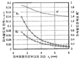
12 is a graph showing the magnetic flux density B ⊥ in the magnet radial direction, the magnetic flux density B // in the magnet rotating direction, and the magnetic flux density amplitude ratio K 'when the sensor is moved in the x-axis direction (direction perpendicular to the rotation axis).
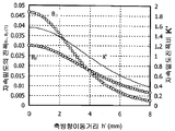
13 is a graph showing the z-axis direction (rotation axis direction) in the magnetic flux density of the magnet in the radial direction when the user moves the sensor ⊥ B, magnetic flux density B //, and a magnetic flux density of the magnetic direction of rotation the amplitude ratio K '.
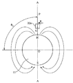
14A is a schematic diagram showing a positional relationship between a magnetic flux of a one-pole pair magnet and a sensor device.
14B is a sectional view taken along the line AA in Fig. 14A.
14C is a schematic view showing various positional relationships between the magnetic flux of the one-pole pair magnet and the sensor device.
15A is a schematic diagram showing a positional relationship between a magnetic flux of a four-pole pair magnet and a sensor device.
Fig. 15B is a sectional view taken along the line AA in Fig. 15A.
15C is a schematic diagram showing the positional relationship between the magnetic flux of the four-pole pair magnet and the sensor device.
15D is a schematic view showing various positional relationships between the magnetic flux of the four-pole pair magnet and the sensor device.
16 is a schematic sectional view showing an example of a rotary machine to which the rotation angle detecting device of the present invention is applied.
17A is a schematic front view showing a rotation angle detecting device of Comparative Example 1. Fig.
17B is a schematic side view showing the rotation angle detecting device of the first comparative example.
17C is a graph showing the sensor output of the rotation angle detecting device of Comparative Example 1. Fig.
17D is a graph showing a detection angle and an error of the rotation angle detecting device of Comparative Example 1. Fig.
18A is a schematic front view showing the rotation angle detecting device of Reference Example 1. Fig.
FIG. 18B is a schematic side view of the rotation angle detecting device of Reference Example 1. FIG.
18C is a graph showing the sensor output of the rotation angle detecting device of the reference example 1. Fig.
18D is a graph showing the detection angle and error of the rotation angle detecting device of Reference Example 1. [Fig.
19A is a schematic front view showing a rotation angle detecting device of Reference Example 2. Fig.
Fig. 19B is a schematic side view showing the rotation angle detecting device of Reference Example 2. Fig.
19C is a graph showing the sensor output of the rotation angle detecting device of Reference Example 2. Fig.
19D is a graph showing a detection angle and an error of the rotation angle detecting device of Reference Example 2. Fig.
20A is a schematic front view showing a rotation angle detecting device of Comparative Example 2. Fig.
20B is a sectional view taken along the line AA in Fig. 20A.
20C is a graph showing the sensor output of the rotation angle detecting device of the second comparative example.
20D is a graph showing a detection angle and an error of the rotation angle detecting device of the second comparative example.
20E is a graph showing the detection angle and error of the rotation angle detecting device of Comparative Example 2 in an enlarged manner.
21A is a schematic front view showing the rotation angle detecting device of Reference Example 3. Fig.
Fig. 21B is a sectional view taken along the line AA in Fig.
FIG. 21C is a graph showing the sensor output of the rotation angle detecting device of Reference Example 3. FIG.
FIG. 21D is a graph showing the detection angle and error of the rotation angle detecting device of Reference Example 3. FIG.
Fig. 21E is a graph showing an enlarged view of the detection angle and error of the rotation angle detecting device of Reference Example 3. Fig.
22A is a schematic front view showing a rotation angle detecting device of Reference Example 4;
22B is a sectional view taken along the line AA in Fig. 22A.
23 is a conceptual diagram showing the overlapping of the sensor devices of Comparative Example 1, Reference Example 1, Reference Example 2, and Example 6, respectively.
24 is a conceptual diagram showing the overlapping of the sensor devices of Comparative Example 2, Reference Example 3, Reference Example 4, Example 7, and Example 8, respectively.
25 is a schematic diagram showing a state in which magnetic flux density amplitudes in the radial direction and the rotational direction of the magnet rotor are measured.
26 is a graph for explaining a method of calculating the amplitude adjustment coefficient K '.
27 is a graph showing the voltage waveform of the sensor output when the correction coefficient k is changed.
28 is a graph showing the relationship between the correction coefficient k and the mechanical angle error.
이하, 본 발명에 대하여, 도면을 참조하여 구체적인 실시 형태를 설명한다. 단, 이들 실시 형태에 의해 본 발명이 한정되는 것은 아니다.DETAILED DESCRIPTION OF THE PREFERRED EMBODIMENTS Hereinafter, the present invention will be described in detail with reference to the drawings. However, the present invention is not limited by these embodiments.
[1] 회전 각도 검출 장치의 실시 형태 [1] Embodiment of rotation angle detecting device
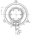
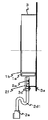
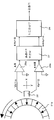
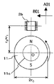
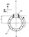
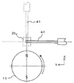
도 1a 및 도 1b에, 외주면에 6극쌍으로 착자된 자석 회전자(1)와, 센서 디바이스(2a)를 지지하는 자기 센서부(21)를 고정한 하우징(3)을 가지는 회전 각도 검출 장치를 나타낸다. 자석 회전자(1)의 회전축은 점 O을 통하여 지면에 수직인 축이다. 센서 디바이스(2a)(고정층 자화 방향이 직교하는 2개의 스핀 밸브형 거대 자기 저항 효과 소자의 브리지 회로를 탑재)에 의해 자석 회전자(1)에 있어서의 링형 영구 자석(1a)의 회전 각도를 검출할 수 있다.1A and 1B show a rotation angle detecting device having a
자석 회전자(1)는, 링형 영구 자석(1a)과, 상기 링형 영구 자석의 내주측에 일체로 형성된 연자성(軟磁性) 링(1b)과, 상기 연자성 링(1b)을 지지하는 비자성(非磁性) 링형의 어댑터(1c)를 구비한다. 자기 센서부(21)는, 주위둘레의 일 측면이 자석 회전자(1)와 대향하는 판형의 회로용 기판(2c)과, 상기 회로용 기판(2c)의 평면에 고정한 센서 디바이스(2a)와, 상기 센서 디바이스(2a) 및 회로용 기판(2c)과 제어용 회로를 전기적으로 접속하는 케이블(2d1) 및 커넥터(2e)와, 상기 센서 디바이스를 덮는 비자성 커버(2f)를 가진다. 링형 영구 자석(1a)은 6극쌍으로 착자되어 있고, 그 착자의 방향이 자석 회전자의 회전축선과 직교하도록 배치되어 있다. 하우징(3)에는, 센서 디바이스(2a)가 소정 간격으로 자석 회전자(1)와 대향하도록, 상기 회로용 기판(2c)을 고정하기 위한 ㄷ자형 앵글(3a) 및 볼트(3c)가 설치되어 있다. 센서 디바이스를 고정한 회로용 기판(2c)의 평면은, 자석 회전자의 회전축선에 대하여 직교하고 있다. 그리고, 센서 디바이스 등의 상세한 것에 대하여는 후술한다.The
도 1a 및 도 1b의 회전 각도 검출 장치는, 자기 센서부(21)를 설치한 하우징(3)을, 볼트 고정용 구멍(3b)을 사용하여 공작 기계 본체에 고정하고, 공작 기계의 샤프트(회전축)에 자석 회전자(1)를(볼트 고정용 구멍(1d)을 사용하여) 동축으로 되도록 고정한다(도 1a 및 도 1b에서는 공작 기계의 도시를 생략하였다). 도 1a에 나타낸 바와 같이, 자석 회전자(1)와 자기 센서부(21)를 대향시킨 상태에서 공작 기계의 샤프트를 회전시킴으로써, 높은 정밀도로 회전 각도를 검출할 수 있다.Rotation angle detecting device of Fig. 1a and 1b is fixed to the housing (3) having a magnetic sensor unit (21), with the bolt fixing holes (3b) to the machine tool body, and the shaft of the machine tool ( And the
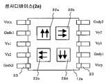
자석 회전자(1)는, NdFeB계 본드 자석으로 이루어지는 링형 영구 자석(1a)과, 연철분(軟鐵粉)과 바인더를 성형하여 이루어지는 연자성 링(1b)과, 상기 연자성 링을 샤프트(회전축)에 장착하기 위한 S45C제의 어댑터(1c)로 구성한다. 센서 디바이스(2a)는, 도 2a 내지 도 2c에 나타낸 바와 같이, 스핀 밸브형 거대 자기 저항 효과 소자(엘리먼트) 8개로 풀 브리지 회로를 구성하여 이루어지고, Vcc와 GND와의 사이에 직류 전압을 인가한 상태에서, 자석 회전자의 자장 내에 센서 디바이스(2a)를 두면, Vx1-Vx2 사이와, Vy1-Vy2 사이에 각각 차동(差動) 출력을 부여한다. 센서 디바이스(2a)는 회로용 기판(2c)을 하우징(3)에 고정하고, 커넥터(2e)에 연결되는 케이블(2d1)을 통하여, 후술하는 도 4의 회로(A-D 변환 보정부 및 각도 연산부로 이루어지는 회로)를 접속하고, A-D 변환 후에 한쪽의 신호에 수정 계수 k를 곱하고(예를 들면, K = 1.6), 각도 연산을 행한다. 센서 디바이스는, 비자성 리드 프레임(lead frame)을 사용하여 10개의 단자(23)를 형성하고, 수지계 재료로 몰딩하여 사용한다. 하우징(3) 및 ㄷ자형 앵글(3a)은 비자성 SUSU316으로 구성하는 것이 바람직하고, ㄷ자형 앵글은 프레스 성형 등에 의해 제작할 수 있다. 회전 각도 검출 장치는, 예를 들면, 자석 회전자(1)의 반경 r0를 25mm, 자석 회전자(1)의 외주면으로부터 센서 디바이스의 중심까지의 거리 r1을 3.5mm, 자석 회전자(1)의 자석의 축방향 두께 t를 4mm, 하우징(3)의 두께 T를 2mm(예를 들면, 2mm 두께의 판재를 펀칭하여, 조여서 형성함)로 한 형상을 가진다. 거리 r1을 6mm까지 크게 한 경우라도 문제없이 사용할 수 있다.The magnetic rotor (1) comprises a ring-like permanent magnet (1a) made of an NdFeB-based bonded magnet, a soft magnetic ring (1b) formed by molding a soft iron powder and a binder, And an adapter 1c made of S45C for mounting on a rotating shaft. As shown in Figs. 2A to 2C, the
도시는 생략하였으나, 도 2a에 나타낸 각각의 한 쌍의 스핀 밸브형 거대 자기 저항 효과 소자(22a~22d)는, 비자성 기판(12a) 상에, 베이스층(Cr)/고정층(Co/Ru/Co)/Cu층/자유층(Co/NiFe)/캡층(Ta)의 순으로 적층하여 패터닝하고, 통전용의 전극막을 형성하고, 절연 피복을 행한 것이다.2A, each of the pair of spin valve type giant magnetoresistive
[2] 회전 각도 검출 장치의 작용 [2] Operation of the rotation angle detecting device
(1) 원리 (1) Principle
유한 축길이의 자석 회전자로부터 발생하는 자속 밀도의 진폭은, 반경 방향과 회전 방향에서 상이하다. 반경 방향의 자속 밀도 성분을 ![]()
![]()
![]()
![]()
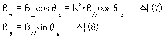
따라서, 자석 회전자의 회전에 따른 자속의 방향 θ mag는 하기의 식(9)에 의해 표현된다. Therefore, the direction ? Mag of the magnetic flux due to the rotation of the magnet rotor is represented by the following equation (9).
![]()
![]()
센서 디바이스의 출력은, 이 각도 θ mag에 의해 정해진다. 반경 방향을 감자축으로 하는 센서 디바이스로부터의 출력 Vx, 및 회전 방향을 감자축으로 하는 센서 디바이스로부터의 출력 Vy에 수정 계수 k를 곱한 출력 Vy·k는, 각각 식(10) 및 식(11)과 같이 된다. The output of the sensor device is determined by this angle ? Mag . Multiplied by the correction factor k of the output V x, and the direction of rotation from the sensor device to the radial direction potato shaft to the output V y from the sensor device as potato brake horsepower V y · k, each
![]()
![]()
![]()
![]()
이 경우, Vx, 및 Vy·k로부터 계산되는 자석 회전자의 회전 각도 θ meas는, 식(12)와 같이 표현된다. In this case, V x, V y · and the rotation angle θ meas of the magnet times the electronic calculated from k is expressed as Equation (12).

식(12)의 tan와 tan-1을 생략하면 식(13)과 같이 된다. If tan and tan -1 in Eq. (12) are omitted, Eq. (13) is obtained.
![]()
![]()
식(13)으로부터, θ meas는 식(14)와 같이 나타내는 것이 가능하다. From equation (13), θ meas can be expressed as in equation (14).
![]()
![]()
식(14)에서, k/K'가 1에 가까울수록 θ meas와 θ e는 가까운 값으로 되어 양자의 오차가 없어진다. k와 K'가 같아지면 k/k' = 1로 되고, tan와 tan-1을 생략하여 θ m e as = θ e 로 된다. 즉, k = K'로 하면 θ meas과 θ e의 오차를 가장 작게 할 수 있다. 즉, 자석 회전자로부터의 반경 방향과 회전 방향의 자속 밀도 진폭이 상이한 경우, 센서 디바이스의 출력에 적절한 전압 진폭 보정을 행함으로써 검출 각도의 오차를 저감시키는 것이 가능하다. 검출 위치는 상기 설명에 있어서는 자석 회전자의 직(直) 가로로 하였으나, 자석에 대한 센서 디바이스의 상대 위치는, 센서 디바이스가 동작하는 자속 밀도의 범위 내에 있어서 임의이다. 즉, 자석으로부터 센서를 반경 방향으로 멀리한 경우에도, 센서를 자석의 회전축 방향으로 이동한 경우에도, 센서 디바이스의 감자면 내에서 직교하는 2개의 감자축 방향의 자속 밀도 진폭비가 변화할 뿐이며, 상기 자속 밀도 진폭비 K'의 값은 일의적으로 결정된다.In Equation (14), as k / K 'approaches 1, θ meas and θ e become close to each other, eliminating the error of both. k and K 'is equal to the ground k / k' and a = 1, by omitting the tan and tan -1 becomes θ m = θ e as e. In other words, when k = K 'may be the smaller the error between θ and θ e meas. That is, when the magnetic flux density amplitude in the radial direction and the rotational direction from the magnet rotor are different, it is possible to reduce the error in the detection angle by performing appropriate voltage amplitude correction on the output of the sensor device. In the above description, the sensing position is a rectangle of the magnet rotor, but the relative position of the sensor device with respect to the magnet is arbitrary within the range of the magnetic flux density at which the sensor device operates. That is, even when the sensor is moved away from the magnet in the radial direction, even when the sensor is moved in the direction of the rotation axis of the magnet, the magnetic flux density amplitude ratio in the two potentiometer axes orthogonal to each other in the sensing surface of the sensor device changes only. The value of the magnetic flux density amplitude ratio K 'is uniquely determined.
(2) 수정 계수 k (2) Correction factor k
수정 계수 k는 3가지 방법에 의해 구할 수 있다. The correction factor k can be obtained by three methods.
(i) 자석의 형상 및 실측(實測)으로부터 결정한 K'값을 사용하는 방법 (i) a method of using the K 'value determined from the shape and actual measurement of the magnet
자석의 회전에 따라 자석 회전자의 주변에서 검출되는 자속 밀도는, 자석의 종류 및 형상에 따라 일의적으로 결정된다. 그러므로, 설계 단계에서 자석의 종류 및 형상, 센서의 위치 및 설치 각도를 결정하면, 센서 브리지의 감자면 내에서 직교하는 2개의 자속 밀도 성분의 진폭비 K'는 결정된다. 따라서, 시뮬레이션이나 실측에 의해 K'를 구하고, 이 값을 수정 계수 k로서 사용한다.The magnetic flux density detected at the periphery of the magnet rotor in accordance with the rotation of the magnet is uniquely determined according to the type and shape of the magnet. Therefore, when the type and shape of the magnet, the position of the sensor and the installation angle are determined in the designing step, the amplitude ratios K 'of the two magnetic flux density components orthogonal to each other in the demagnetizing plane of the sensor bridge are determined. Therefore, K 'is obtained by simulation or actual measurement, and this value is used as the correction coefficient k.
(ii) 센서의 출력으로부터 구한 k'값을 사용하는 방법 (ii) a method of using the k 'value obtained from the output of the sensor
소정의 위치에 센서를 설치하고, 자석 회전자를 일정 속도로 회전시킨 경우, 센서 디바이스의 출력 파형은 주기 함수로 된다. 자석 회전자로부터 발생하는 자속 밀도가 정현파형이라도, 감자면 내에서 직교하는 자속 밀도의 진폭이 상이하므로, 센서 출력은 고조파를 포함한 파형으로 된다. 센서 브리지로부터의 출력을 푸리에 전개하면, 하기의 식(1-1) 및 식(1-2)에 의해 표현된다. When a sensor is provided at a predetermined position and the magnet rotor is rotated at a constant speed, the output waveform of the sensor device becomes a periodic function. Even if the magnetic flux density generated from the magnet rotor is a sine wave type, the amplitude of the magnetic flux density orthogonal to the magnetic flux density in the demagnetizing plane is different, and the sensor output becomes a waveform including harmonics. When the output from the sensor bridge is Fourier-expanded, it is expressed by the following equations (1-1) and (1-2).

식(1-1) 및 식(1-2)에 있어서, Vx는 자석 회전자의 반경 방향을 감자축으로 하는 센서 브리지의 출력 전압, Vy는 자석 회전자의 회전 방향을 감자축으로 하는 센서 브리지의 출력 전압이다. 각 출력 전압의 5차 이후의 고조파의 영향은 경미하기 때문에, 3차 고조파까지를 고려한 경우, 진폭 조정 비율 k'의 값은 하기의 식(2)에 의해 표현된다. In the equations (1-1) and (1-2), V x denotes the output voltage of the sensor bridge having the magnet rotor as a potentiometer axis, and V y denotes a rotation direction of the magnet rotor as a potentiometer axis The output voltage of the sensor bridge. Since the influence of the harmonics after the fifth order of each output voltage is slight, when the third harmonic is considered, the value of the amplitude adjustment ratio k 'is expressed by the following expression (2).
![]()
![]()
이 진폭 조정 비율 k'를 수정 계수 k로서 사용한다.This amplitude adjustment ratio k 'is used as a correction coefficient k.
식(1-1) 및 식(1-2)와 식(2)와의 관계에 대하여 상세하게 설명한다. The relationship between Equation (1-1) and Equation (1-2) and Equation (2) will be described in detail.
진폭 조정 비율 k'는, 식(1-1) 및 식(1-2)의 센서 브리지의 출력 전압의 출력 진폭을 정규화한 Vx 및 Vy의 기본파 성분과 3차 고조파 성분으로부터 구한 값이며, Vx 출력의 기본파 푸리에 계수를 a1, 3차 고조파 푸리에 계수를 a3, Vy 출력의 기본파 푸리에 계수를 b1, 3차 고조파 푸리에 계수를 b3로 하여 식(2)에 의해 구할 수 있다. 이 진폭 조정 비율 k'는 자속 밀도의 진폭비 K'와 같은 값이다. 이하에 그 증명을 행한다.The amplitude adjustment ratio k 'is a value obtained from the fundamental wave component and the third harmonic component of V x and V y obtained by normalizing the output amplitude of the output voltage of the sensor bridge of the formulas (1-1) and (1-2) by the fundamental wave Fourier coefficient for a 1, 3-harmonic Fourier coefficients for a 3, V y fundamental wave Fourier coefficient a b 1, 3-harmonic Fourier coefficients of the output of the V x output to b 3 by the following formula (2) Can be obtained. This amplitude adjustment ratio k 'is equal to the amplitude ratio K' of the magnetic flux density. Proof is given below.
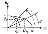
지금, 회전 방향의 자속 밀도 진폭에 의해 정규화된 y 방향의 자속 밀도 순간값을 y0이라고 한다. x방향의 자속 밀도 진폭이 y 방향의 그것과 같은 경우의 순간값을 x0로 하면, x방향의 자속 밀도 진폭이 K'배인 경우에는, 도 26에 나타낸 바와 같이, x방향의 자속 밀도 순간값은 K'x0로 된다. 즉, (x0, y0)의 점은 x = cosθ, y = sinθ로 표현되는 원 상에 있고, (K'x0, y0)의 점은 x = K'·cosθ', y = sinθ'로 표현되는 타원 상에 있다. 여기서, x0, y0, K', θ 및 θ'의 관계는, 하기의 식(15-1) 및 식(15-2)와 같이 된다. Now, the instantaneous value of the magnetic flux density in the y direction normalized by the magnetic flux density amplitude in the rotational direction is referred to as y 0 . Assuming that the instantaneous value in the case where the amplitude of the magnetic flux density in the x direction is equal to that in the y direction is x 0 , if the amplitude of the magnetic flux density in the x direction is K 'times, as shown in FIG. 26, Becomes K'x 0 . That is, the point x = K '· cos θ' of the points in the (x 0, y 0) is on a circle represented by x = cos θ, y = sin θ, (

이들 식으로부터 tanθ = K'·tanθ'가 도출된다. 또한, 도 26으로부터 명백한 바와 같이, 하기의 식(16-1) 내지 식(16-4)가 도출된다. From these equations, tan ? = K ' ? Tan ? ' Is derived. Further, as apparent from Fig. 26, the following equations (16-1) to (16-4) are derived.

또한, 식(16-1) 내지 식(16-4)로부터, 식(17)이 도출된다. From equation (16-1) to equation (16-4), equation (17) is derived.

마찬가지로, sinθ'를 계산하면, 식(18)이 도출된다. Similarly, by calculating sin ? ', Equation (18) is derived.
![]()
![]()
여기서, 식(19)와 같이 C를 정의하면, Here, if C is defined as in equation (19)
![]()
![]()
cosθ' 및 sinθ'는 각각, cosθ' = K'·C·cosθ 및 sinθ' = C·sinθ로 변형시킬 수 있다. 이들이, 출력 전압을 정규화한 센서 브리지 출력에 상당하고, Vx = cosθ' 및 Vy = sinθ'이다.cos ? 'and sin ? ' can be transformed into cos ? '= K' ? C ? cos ? and sin ? '= C ? sin ? , respectively. These correspond to a sensor bridge output that normalizes the output voltage, and V x = cos θ 'and V y = sin θ '.
한편, Vx와 Vy와의 각각에 대하여, 교류분만을 고려하여 푸리에 전개하고, 유의(有意)한 항만을 남기면 하기의 식(20) 및 식(21)을 얻을 수 있다. On the other hand, the following equations (20) and (21) can be obtained by performing Fourier expansion for each of V x and V y in consideration of alternating delivery and leaving a significant port.

상기 식에 있어서의 a1, a3, b1 및 b3는, 각각 푸리에 계수이며, 하기의 식(22-1) 내지 식(22-4)에 의해 표현된다. A 1 , a 3 , b 1 and b 3 in the above equations are Fourier coefficients respectively and expressed by the following equations (22-1) to (22-4).


따라서, ![]()
![]()

여기서, 분모의 적분 내는 하기 식(24)로 된다. Here, the integral of the denominator is expressed by the following equation (24).

한편, 분자의 적분 내는 하기 식(25)로 된다. On the other hand, the integral of the molecule is expressed by the following equation (25).

적분 내의 분자와 분모가 같으므로, 식(23)은 식(26)인 것이 증명된다. Since the numerator and denominator in the integral are the same, equation (23) is proved by equation (26).
![]()
![]()
이같이 하여 직교하는 감자축을 가지는 스핀 밸브형 거대 자기 저항 효과 소자(SVGMR 소자) 브리지의 출력 파형의 기본파 및 3차 고조파의 푸리에 계수에 의해 구한 진폭 조정 비율 k'를 수정 계수 k로서 사용한다.Thus, the amplitude adjustment ratio k 'obtained by the fundamental wave of the output waveform of the spin valve type giant magnetoresistance effect element (SVGMR element) bridge having the orthogonal demagnetizing axis and the Fourier coefficient of the third harmonic is used as the correction coefficient k.
그리고, Vy의 파형의 위상이 Vx의 파형보다 약 90도 진행하고 있는 경우에는, 수정 계수 k를 식(27)로 나타내는 것도 가능하다. And, in the case of the phase of the waveform of the V y is in progress by about 90 than the waveform of the V x, it is also possible that represents the correction factor k by equation (27).
![]()
![]()
Vx와 Vy는, 푸리에 전개할 때 sin와 cos를 교체하여 하기와 같이 표기할 수도 있다. 즉, Vx 및 Vy의 각각에 대하여, 교류분만을 고려하여 푸리에 전개하고, 유의한 항만을 남기면 식(28) 및 식(29)를 얻을 수 있다. V x and V y can be written as follows by replacing sin and cos when Fourier expansion. That is, for each of V x and V y, the equations (28) and (29) can be obtained by performing the Fourier expansion considering the alternating current delivery and leaving a significant port.

이 경우, 증명은 생략하지만 k는 식(30)에 의해 표현된다. In this case, the proof is omitted, but k is expressed by equation (30).
![]()
![]()
그리고, Vx 및 Vy의 위상 관계는, 센서의 배치 방법이나 회전자의 회전 방향에 따라 변화되므로, Vx 및 Vy의 1차의 푸리에 계수가 어느 한 쪽, 또는 양쪽이 마이너스로 되는 경우도 있을 수 있다. 그 경우라도 같은 수식 내에서의 1차의 계수와 3차의 계수와의 부호는 함께 변하므로 식 전체의 절대값을 취하는 것에 의해 k는 플러스의 수로 된다.Then, the phase relationship between V x and V y is the case since the change with the rotation direction of the alignment of the sensor and the rotor, the Fourier coefficient of the first of the V x and V y of either, or both are negative There may also be. Even in this case, the sign of the first order coefficient and the third order coefficient in the same expression change together, so that k is a positive number by taking the absolute value of the whole expression.
(iii) k에 대한 기계각 오차의 변화율로부터 구하는 방법 (iii) a method of obtaining from the rate of change of the machine angular error with respect to k
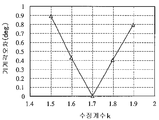
수정 계수 k로서 임의의 값을 2점 이상(바람직하게는 3점 이상) 설정하고, 각각의 값을 실제로 출력 전압값에 곱하여 기계각을 산출하고, 실제의 자석 회전자의 기계각과 비교하여 기계각 오차를 구하고, 그 각 점의 결과로부터 최적의 수정 계수 k를 얻는다. 이 때, 만일 설정한 2점 이상의 k값과 그에 대한 기계각 오차와의 관계는 적당한 근사식(예를 들면, 직선 근사)을 사용하여 최소 제곱법으로 구하는 것이 바람직하다. 예를 들면, 도 28에 나타낸 바와 같이, 만일 설정한 5점의 수정 계수(k1 = 1.5, k2 = 1.6, k3 = 1.7, k4 = 1.8 및 k5 = 1.9)를 사용하여 기계각 오차를 구하고, 가로축에 수정 계수 k의 값, 세로축에 기계각 오차의 값을 취하여 그래프화하고, 각각의 측정값에 근접하는 직선을 잇는 것으로 기계각 오차가 0 deg.로 되는 수정 계수 k를 구할 수 있다. 도 28에 나타낸 경우에는, K = 1.7일 때 기계각 오차가 0 deg.로 된다.The mechanical angle is calculated by multiplying an actual value of the output voltage by each of two or more values (preferably three or more points) as an arbitrary value as the correction coefficient k, And an optimum correction coefficient k is obtained from the result of each point. At this time, it is preferable that the relationship between the set k values of two or more points and the mechanical angle error therefrom is determined by a least squares method using a suitable approximate expression (for example, linear approximation). For example, as shown in Fig. 28, if the set correction coefficients k 1 = 1.5, k 2 = 1.6, k 3 = 1.7, k 4 = 1.8 and k 5 = 1.9), and plotting the values of the correction factor k on the abscissa and the values of the mechanical angular error on the ordinate, and connecting the straight lines approaching the respective measured values, The correction coefficient k can be obtained. In the case shown in Fig. 28, the mechanical angle error becomes 0 deg when K = 1.7.
(3) 실시 형태 (3) Embodiment
(i) 수정 계수 k의 산출 (i) Calculation of correction factor k
수정 계수 k는, 예를 들면, 도 3의 개념도에 나타낸 방법에 의해 산출할 수 있다. 자석 회전자 근방의 원하는 위치에 설치한 센서 디바이스(32)에 의해 자석 회전자(31a)의 회전에 따른 자속의 방향을 검지하고, 센서 브리지로부터의 출력 전압(Vx, Vy)을 오실로스코프(oscilloscope)(27b)에 의해 측정한다. 얻어진 측정값을 퍼스널 컴퓨터(28b)에 입수하고, 전기각 1주기의 푸리에 연산에 의해, 상기 식(1-1), 식(1-2) 및 식(2)를 사용하여 k'를 산출한다. 이 방법은, 센서 디바이스(32)에 장착한 후에 보정이 가능하므로, 장착 위치의 어긋남에 의한 기계각 오차의 증가를 억제할 수 있어, 실용상 편리한 방법이다. 통상, 수정 계수 k는 이 k' 그 자체의 값을 이용하면 된다.The correction coefficient k can be calculated, for example, by the method shown in the conceptual diagram of Fig. Magnet rotor near the oscilloscope to the output voltage (V x, V y) from the sensor bridge detects a direction of magnetic flux, and in accordance with the rotation of the magnet rotor (31a) by a
(ii) 진폭 보정 방법 1(ii)
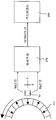
회전 각도 검출 장치의 일 실시 형태를 도 4에 개념적으로 나타낸다. 6극쌍 자석 근방의 원하는 위치에 설치한 센서 디바이스(32)에 의해 자석 회전자(31a)의 회전에 따른 자속의 방향을 검지하고, 센서 브리지로부터의 출력 전압(Vx, Vy)을 각각 A-D 변환(아날로그-디지털 변환)하고, 변환 후 Vy에 미리 산출하여 둔 수정 계수 k를 곱하고, 이 출력 전압(Vx, k·Vy)을 각도 연산부(28)에 의해 역정접 연산함으로써 각도를 검출한다. 이 방법은, 전압 조정을 디지털로 행하므로, 전단(前段)의 전자 회로를 단순하게 구성할 수 있는 데 더하여 A-D 변환의 측정 범위를 최대로 취할 수 있는 것이다.An embodiment of the rotation angle detecting device is conceptually shown in Fig. 6 geukssang detecting the direction of the magnetic flux according to rotation of the magnet rotor (31a) by means of a
(iii) 진폭 보정 방법 2(iii)
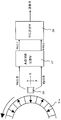
회전 각도 검출 장치의 다른 일 실시 형태를 도 5에 개념적으로 나타낸다. 6극쌍 자석 근방의 원하는 위치에 설치한 센서 디바이스(32)에 의해 자석 회전자(31a)의 회전에 따른 자속의 방향을 검지하고, 센서 브리지의 출력 전압 Vx만 미리 산출하여 둔 수정 계수 k로 나누어(즉, 가변 저항기를 사용하여 분압하여), A-D 변환 보정부(27)에 입력한다. 이들 출력 전압(Vx/k, Vy)을 각도 연산부(28)에 의해 역정접 연산함으로써 각도를 검출한다. 이 방법은, 검출 각도와 실제의 회전 각도를 평가하면서, 수정 계수 k를 결정할 수 있는 것이다.Another embodiment of the rotation angle detecting device is conceptually shown in Fig. 6 geukssang a correction factor k based calculates magnet once detecting the direction of magnetic flux in accordance with the rotation of electron (31a), and only the output voltage V x of the sensor bridge in advance by a
(iv) 진폭 보정 방법 3(iv)
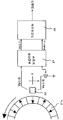
회전 각도 검출 장치의 또 다른 일 실시 형태를 도 6에 개념적으로 나타낸다. 6극쌍 자석 근방의 원하는 위치에 설치한 센서 디바이스(32)에 의해 자석 회전자(31a)의 회전에 따른 자속의 방향을 검지하고, 센서 브리지의 출력 전압(Vx, Vy)을 각각 오피 앰프(26a, 26b)에 입력한다. 그 때, Vx의 증폭률을 A로 하고, Vy의 증폭률을 A·k로 하여 전압을 조정한다. 그 후, A-D 변환 보정부(27)에 입력하고, 출력 전압(A·Vx, k·A·Vy)을 각도 연산부(28)에 의해 역정접 연산함으로써 각도를 검출한다. 이 방법은, 센서 브리지 출력을 증폭할 수 있으므로, 증폭부를 차동으로 함으로써, 내노이즈성을 향상시킬 수 있는 등의 장점이 있다.Another embodiment of the rotation angle detecting device is conceptually shown in Fig. 6 detects the direction of the magnetic flux according to rotation of the magnet rotor (31a) by means of a
본 발명을 이하의 실시예에 의해 보다 상세하게 설명하지만, 본 발명은 이들에 한정되는 것은 아니다.The present invention is explained in more detail by the following examples, but the present invention is not limited thereto.
[실시예 1][Example 1]
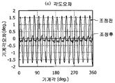
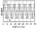
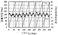
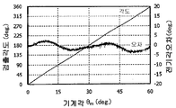
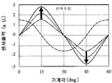
1극쌍 자석 회전자를 사용한 회전 각도 검출 장치를 제작하였다. 자석 회전자로서 직경 26mm 및 축방향 두께 5mm의 NdFeB계 본드 자석을 사용하고, 센서 디바이스는 자석 외주의 표면으로부터 5mm 떨어진 개소에 배치하였다. 1극쌍 자석을 사용하였으므로, 도 7a에 나타낸 바와 같이, 자석 회전자 1회전(기계각 360 deg.)에 대하여 1주기의 센서 브리지 출력을 얻을 수 있었다(전압 조정 전). 이 출력을 푸리에 전개하여 전술한 식(1-1), 식(1-2) 및 식(2)에 의해 k'를 구한 바, k' = 1.70이었다. 이 k'를 수정 계수 k로 하여 Vy에 곱하여, 도 7b에 나타낸 바와 같은 출력 k·Vy를 얻었다. 도 7a 및 도 7b의 출력 파형을 각각 역정접 연산하여 각도 오차를 평가한 결과, 도 7c에 나타낸 바와 같이, 전압 조정 전은 ±15 deg.정도 발생하고 있었던 기계각 오차를, 전압 조정을 행함으로써 ±0.5 deg. 정도로 저감할 수 있었다.A rotating angle detecting device using a one-pole pair magnet rotor was manufactured. An NdFeB bonded magnet having a diameter of 26 mm and an axial direction thickness of 5 mm was used as the magnet rotor, and the sensor device was disposed at a
[실시예 2][Example 2]
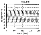
4극쌍 자석 회전자를 사용한 회전 각도 검출 장치를 제작하였다. 자석 회전자로서 외측 직경 40mm, 내측 직경 34mm 및 축방향 두께 4mm의 NdFeB계 본드 자석을 사용하고, 센서 디바이스는 자석 외주의 표면으로부터 5mm 떨어진 개소에 배치하였다. 4극쌍 자석을 사용하였으므로, 도 8a에 나타낸 바와 같이, 자석 회전자 1회전(기계각 360 deg.)에 대하여 4주기의 센서 브리지 출력을 얻을 수 있었다(전압 조정 전). 이 출력의 전기각 1주기(기계각으로 90deg.)를 푸리에 전개하여 실시예 1과 마찬가지로 하여 k'를 구한 바, k' = 1.67이었다. 이 k'를 수정 계수 k로 하여 Vy에 곱하여 도 8b에 나타낸 바와 같은 출력 k·Vy를 얻었다. 도 8a 및 도 8b의 출력 파형을 각각 역정접 연산하여 각도 오차를 평가한 결과, 도 8c에 나타낸 바와 같이, 전압 조정 전은 ±3.5 deg.정도 발생하고 있었던 기계각 오차를, 전압 조정을 행함으로써 ±0.4 deg. 정도로 저감할 수 있었다.A rotation angle detector using a 4-pole magnet rotor was fabricated. An NdFeB bonded magnet having an outer diameter of 40 mm, an inner diameter of 34 mm and an axial direction thickness of 4 mm was used as the magnet rotor, and the sensor device was disposed at a
[실시예 3][Example 3]
8극쌍 자석 회전자를 사용한 회전 각도 검출 장치를 제작하였다. 자석 회전자로서, 외측 직경 120mm, 내측 직경 112mm 및 축방향 두께 6mm의 NdFeB계 본드 자석을 사용하고, 센서 디바이스는 자석 외주의 표면으로부터 6mm 떨어진 개소에 배치하였다. 8극쌍 자석을 사용하였으므로, 도 9a에 나타낸 바와 같이, 자석 회전자 1회전(기계각 360 deg.)에 대하여 8주기의 센서 브리지 출력을 얻을 수 있었다(전압 조정 전). 이 출력의 전기각 1주기(기계각으로 45 deg.)를 푸리에 전개하여 실시예 1과 마찬가지로 하여 k'를 구한 바, k' = 1.67이었다. 이 k'를 수정 계수 k로 하여 Vy에 곱하여 도 9b에 나타낸 바와 같은 출력 k·Vy를 얻었다. 도 9a 및 도 9b의 출력 파형을 각각 역정접 연산하여 각도 오차를 평가한 결과, 도 9c에 나타낸 바와 같이, 전압 조정 전에는 ±1.8 deg. 정도 발생하고 있었던 기계각 오차를, 전압 조정을 행함으로써 ±0.2 deg. 정도로 저감할 수 있었다.A rotation angle detecting device using an 8-pole magnet rotor was fabricated. An NdFeB bonded magnet having an outside diameter of 120 mm, an inside diameter of 112 mm, and an axial direction thickness of 6 mm was used as the magnet rotor, and the sensor device was disposed at a
(전압 조정값 변화에 의해 발생하는 오차)(Error caused by voltage adjustment value change)
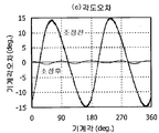
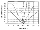
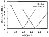
극대수 N가 1, 4 및 8의 자석 회전자를 구비한 본 발명의 회전 각도 검출 장치에 있어서, 수정 계수 k를 변화시켰을 때의 기계각 오차의 계산 결과를 도 10에 나타낸다. 여기서, 센서 브리지 감자면의 위치에서의 직교하는 자속 밀도의 진폭비 K'를 1.70으로 하였다. 어느 극대수의 자석 회전자에 있어서도, 수정 계수 k를 자속 밀도 진폭비 K'와 동등하게 하는 것에 의해 기계각 오차는 최소로 되었다. 극대수 N을 증가시키면, 기계각 오차가 1/N로 되므로, 수정 계수 k의 어긋남에 의한 오차의 증가는 억제된다. 예를 들면, 기계각 오차의 절대값을 5 deg. 이하로 할 필요가 있는 경우, 허용되는 수정 계수 k의 어긋남은 ±0.3N(N은 자석 회전자의 극대수) 정도이므로, k = K'±0.3N의 범위로 하는 것이 바람직하다. k의 값은, k = K'±0.2N의 범위인 것이 보다 바람직하고, k = K'±0.1N의 범위인 것이 가장 바람직하다. 또한, 기계각 오차의 절대값을 1 deg. 이하로 할 필요가 있는 경우, 허용되는 수정 계수 k의 어긋남은 ±0.06N(N은 자석 회전자의 극대수) 정도로 된다. 이 허용량이 클수록, 공업적으로 이용하기 쉽다고 말할 수 있다. 또한, 기계각 오차의 절대값을 0.5 deg. 이하로 하는 데는, 허용되는 수정 계수 k의 어긋남은 ±0.03N으로 된다. 또한, 자속 밀도 진폭비 K'를 1.4 및 1.7의 각각의 경우의, 수정 계수 k에 대한 전기각 오차의 계산 결과를 도 11에 나타낸다. 각도 오차는 자속 밀도 진폭비 K'를 1.7로 했을 때도, 1.4로 했을 때도 대략 동일한 범위로 되었다.Fig. 10 shows calculation results of the machine angular error when the correction coefficient k is changed in the rotation angle detecting device of the present invention having the magnetic rotors of the maximum number N of 1, 4 and 8. Here, the amplitude ratio K 'of the orthogonal magnetic flux density at the position of the sensor bridge electromagnet was 1.70. In any of the maximum number of magnet rotors, the mechanical angle error is minimized by making the correction coefficient k equal to the magnetic flux density amplitude ratio K '. If the maximum number N is increased, the mechanical angular error becomes 1 / N, so that an increase in error due to the deviation of the correction coefficient k is suppressed. For example, if the absolute value of the machine angle error is 5 deg. The deviation of the allowable correction coefficient k is about ± 0.3 N (where N is the maximum number of the magnet rotors), so that it is preferable to set the range of k = K '± 0.3 N. The value of k is more preferably in the range of k = K '± 0.2N, and most preferably in the range of k = K' ± 0.1N. Also, the absolute value of the machine angular error is 1 deg. Or less, deviation of the allowable correction coefficient k is about 0.06 N (N is the maximum number of the magnet rotors). The larger the allowable amount, the easier it can be said to be industrially useful. Also, the absolute value of the machine angular error is 0.5 deg. Or less, the allowable deviation of the correction coefficient k is ± 0.03 N. 11 shows the results of calculation of the electrical angle error with respect to the correction coefficient k in the cases of the flux density amplitude ratio K 'of 1.4 and 1.7, respectively. The angular error was approximately the same when the magnetic flux density amplitude ratio K 'was 1.7 or 1.4.
[실시예 4][Example 4]
6극쌍 자석 회전자(외측 직경 50mm, 내측 직경 45mm 및 축방향 두께 4mm의 NdFeB계 본드 자석)에 있어서의 자석 반경 방향의 자속 밀도 진폭 B⊥, 회전 방향의 자속 밀도 진폭 B//, 및 양자로부터 구한 자속 밀도 진폭비 K'의 측정 위치 의존성을 평가했다. 자석 회전자 외주 표면(자석 두께 방향 중앙)을 기준 위치로 하고, x축 방향(회전축과 수직인 방향)으로 r1 어긋나게 한 위치에서의 B⊥, B// 및 K'의 측정 결과를 도 12에 나타낸다. 자석 회전자로부터 발생하는 자속 밀도 진폭은 B⊥가 크고, 자속 밀도 진폭비 K'는 측정 범위 내에 있어서 1.4 내지 1.9였다.The magnetic flux density amplitude B ⊥ in the magnet radial direction, the magnetic flux density amplitude B // in the rotating direction in the magnet radial direction in the six-pole pair magnet rotor (NdFeB bonded magnet having the outside diameter of 50 mm, the inside diameter of 45 mm and the axial direction thickness of 4 mm) The measured position dependence of the magnetic flux density amplitude ratio K 'was evaluated. The measurement results of B ⊥ , B // and K 'at positions where the magnetic rotor outer circumferential surface (center in the magnet thickness direction) is the reference position and shifted by r 1 in the x axis direction (direction perpendicular to the rotation axis) Respectively. The magnetic flux density amplitude generated from the magnet rotor was large in B ⊥ , and the magnetic flux density amplitude ratio K 'was 1.4 to 1.9 within the measurement range.
또한, r1 = 3.5mm의 위치로부터 z축 방향(회전축 방향)으로 h' 어긋나게 한 위치에서의 B⊥, B// 및 K'의 측정 결과를 도 13에 나타낸다. h'의 값이 커짐에 따라 B⊥가 급격하게 감소하므로 K'도 크게 감소하고, z = 4mm 이상에서 B//쪽이 크게 되었다.13 shows the results of measurement of B ?, B // and K 'at a position shifted by h' from the position of r 1 = 3.5 mm in the z-axis direction (rotation axis direction). As the value of h 'increases, B ⊥ decreases drastically, so that K' also decreases drastically and B // increases at z = 4 mm or more.
상기 자석 회전자와 센서 디바이스를 사용하여 회전 각도 검출 장치를 구성하고, 임의의 측정 위치 r1에 있어서 얻어진 K'를 수정 계수 k로서 사용하여 진폭 보정 방법 1 내지 보정 방법 3에 적용한 바, 각도 오차를 억제한 회전 각도 검출 장치를 얻을 수 있었다. 이와 같이, 자석 회전자의 형상, 극대수, 센서 디바이스의 설치 위치를 결정하면, 자속 밀도 진폭비 K'를 용이하게 구할 수 있고, 그 값을 수정 계수 k로서 사용함으로써 각도 오차를 억제한 회전 각도 검출 장치를 제작할 수 있는 것을 알 수 있었다.When the rotation angle detecting device is constituted by using the magnet rotor and the sensor device and K 'obtained at an arbitrary measurement position r 1 is applied to the
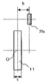
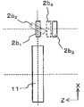
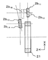
자석 회전자로서 1극쌍 자석을 사용했을 때의 자속과 센서 디바이스(32a)와의 위치 관계를 도 14a 및 도 14b에 나타낸다. 곡선형의 한쪽 화살표는, 2극의 원판형 자석(11)의 자극 표면으로부터 발생하는 자력선을 나타낸다. Z축은, 원판형 자석(11)의 중심 O(자석의 두께 중심점)을 원점으로 하여 자석의 회전 평면과 직교하는 축이며, 자석 회전자의 회전축에 상당한다. X축 및 Y축은, 상기 중심 O을 원점으로 하여 각각 Z축에 수직인 축이며, 도 14a에 나타낸 위치 관계에 있을 때의 자석의 자화 방향을 X축으로 하고, 자화 방향과 직교하는 방향을 Y축으로 하였다. 센서 디바이스(32a)의 감자면의 중심은 자석 표면으로부터 r1 떨어진 X축 상에 있고(z = 0, φ = 0°), 그 감자면은 Z축과 직교하도록 (χ = 0°) 배치하였다. 이 때, 센서 디바이스(32a)는 반경 방향의 자속 밀도 성분 Br만을 받고 있다. θ m은 자석 회전자의 회전 각도에 상당한다. 예를 들면, 도 14a의 상태의 원판형 자석(11)을 원주 방향으로 기계각 θ m으로 90deg.만큼 회전시키면, 센서 디바이스(32a)는 회전 방향의 자속 밀도 성분 B θ 만을 받게 된다.14A and 14B show the positional relationship between the magnetic flux and the
센서 디바이스는, 예를 들면, 도 14c에 나타낸 바와 같이, 다양한 위치에 배치할 수 있다. 도 14c는, 3종류의 회전 각도 검출 장치에서의 센서 디바이스(32b, 32b', 32b")의 위치 관계를 알기 쉽게 하기 위해 편의상 중첩시켜 나타낸 것이다. 센서 디바이스(32b)는, X-Y 평면 상(Z = 0)에 센서 디바이스의 감자면의 중심을 배치하고, 그 감자면을 X-Y 평면에 대하여 χ만큼 경사지게 했다. 센서 디바이스(32b')는, X-Y 평면으로부터 z축 방향으로 h' 떨어진 위치(센서 배치 각 φ'의 위치)에 센서 디바이스의 감자면의 중심을 배치하고, 그 감자면을 X-Y 평면에 대하여 χ'만큼 경사지게 하였다. 센서 디바이스(32b')의 위치에 있어서, 자속의 방향은 X축으로부터 ε' 경사져 있다. 이 경우에도, 회전 축선 방향은 지면(紙面) 수직 방향이며, 반경 방향은 지면 상방향이다. 센서 디바이스(32b")는, 그 감자면의 중심이 자석 회전자의 원판형 자석의 회전축선 상에 있고(φ" = 90deg.), 감자면이 X-Y 평면과 평행(χ" = 180 deg.)이다. 이 위치에서의 자속의 방향ε" = 180 deg.이다. 그리고, 원판형 자석(11)을, z축 방향의 두께 t를 크게 한 원기둥형 자석, 중심에 관통공을 형성한 링형 자석, 또는 직사각형 판형 자석으로 치환해도, 1극쌍 자석이면 전술한 각도 등의 정의는 마찬가지로 성립된다.The sensor device can be arranged at various positions, for example, as shown in Fig. 14C. 14C is superimposed for the sake of convenience in order to facilitate understanding of the positional relationship of the
자석 회전자로서 4극쌍 자석을 사용했을 때의 자속과 센서 디바이스와의 위치 관계를 도 15a 및 도 15b에 나타낸다. 직선형의 굵은 화살표는 자석 회전자의 링형 영구 자석(31b)의 각 자극 내의 자화의 방향을 나타내고, 곡선형의 굵은 화살표는 자극 표면으로부터 발생하는 자속을 나타낸다. λ는 표면 자속 밀도 분포를 측정했을 때의 신호의 1파장(전기각 θ e으로 360 deg.)에 상당하고, 링형 영구 자석(31b)에서는 한 쌍의 자극 표면의 주위 방향 길이에 상당한다. Z축은, 링형 영구 자석(31b)의 구멍의 중심 O을 통하여 자석의 회전 평면과 직교하는 축이며, 자석 회전자의 회전축에 상당한다. X축 및 Y축은, 상기 중심 O을 원점으로서 각각 Z축에 수직인 축이며, 도 15a에 나타낸 위치 관계에 있을 때의 자석의 자화 방향을 X축으로 하고, 자화 방향과 직교하는 방향을 Y축으로 했다. 센서 디바이스(32c)의 감자면의 중심은 링형 영구 자석(31b)의 표면으로부터 r1 떨어진 X축 상에 있고(z = 0, φ' = 0°), 그 감자면은 Z축과 직교하도록(χ = 0°) 배치하였다. 이 때, 센서 디바이스(32c)는 X축의 방향의 자속을 받고 있다. 링형 영구 자석(31b)을 주위 방향으로 전기각 θ e으로 90deg.만큼 회전시켰을 때, 센서 디바이스(32c)는 링형 영구 자석(31b)의 자극 사이에 위치하고, 센서 디바이스(32c)는 Y축의 방향의 자속을 받게 된다.Figs. 15A and 15B show the positional relationship between the magnetic flux and the sensor device when a four-pole pair magnet is used as the magnet rotor. The thick straight arrow indicates the direction of magnetization in each magnetic pole of the ring-shaped
도 15c에 나타낸 센서 디바이스(32d)는, 자속의 측정 방향을 자석 회전자의 반경 방향(또는 회전 방향)으로부터 ξ만큼 경사지게 한 것이다. 이와 같은 경우라도, ξ가 10° 이내이면 수정 계수 k는 상기와 같이 산출한 값을 채용할 수 있다. 즉, 센서 브리지의 검출 방향이 자석 회전자의 반경 방향(또는 회전 방향)으로부터 다소 어긋나 있었다고 해도, 수정 계수 k는 자석 회전자의 반경 방향 및 회전 방향에서의 진폭비, 또는 이들 파형을 푸리에 전개한 식(1-1) 및 식(1-2)의 a1, a3, b1 및 b3의 수치로부터 구해지는 값을 채용할 수 있다.The
센서 디바이스는, 예를 들면, 도 15d에 나타낸 바와 같이 몇 개소의 위치에 배치할 수 있다. 도 15d는, 3종류의 회전 각도 검출 장치에서의 센서 디바이스(32e, 32e', 32e")의 위치 관계를 알기 쉽게 하기 위해 편의상 중첩시켜 나타낸 것이다. 센서 경사각 χ, 센서 배치각 φ', 센서 경사각 χ', h' 및 ε'의 정의는 도 14c와 같다. 이 링 자석의 구멍에는 회전축으로 되는 샤프트를 고정시킬 수 있다.The sensor device can be arranged at several positions, for example, as shown in Fig. 15D. Fig. 15D shows the positional relationship of the
[실시예 5][Example 5]
실시예 3의 회전 각도 검출 장치를 적용한 회전기를 도 16에 모식적으로 나타낸다. 이 회전기는 모터이며, 프레임(73c) 내에는, 중심축으로서 샤프트(71b)를 가지는 12극의 영구 자석의 로터(71a)와, 프레임(73c)의 내주면에 고정한 고정자용 코일(73b)이 설치된 고정자(73a)를 가진다. 샤프트(71b)는 베어링(도시하지 않음)을 통하여 프레임(73c)에 회전 가능하게 지지되어 있다. 자석 회전자(71c)는, 상기 로터(71a)와 인접하도록 샤프트(71b)에 동축으로 설치하고, 센서 디바이스(72a)는 지지부(72d)를 통하여, 상기 자석 회전자(71c)의 직(直) 가로로 배치되도록 프레임(73c)에 고정하였다. 상기 자석 회전자(71c)로부터 인가되는 자속의 방향을 상기 센서 디바이스(72a)로 검지하고, 그 출력을 연산 회로(72c)로 처리하고, 자석 회전자(71c)의 회전 각도를 출력하였다. Fig. 16 schematically shows a rotary machine to which the rotation angle detecting device of the third embodiment is applied. This rotor is a motor. In the frame 73c, a
[비교예 1][Comparative Example 1]
2극으로 착자된 자석 회전자의 원판형 자석(11)의 외주에, 도 17a 및 도 17b에 나타낸 바와 같이 센서 디바이스(2b)를 배치한 회전 각도 검출 장치를 제작하였다. 여기서는 원판형 자석(11)의 중심 O을 원점으로 하고, 회전축을 Z축으로 한 원기둥 좌표계를 사용하여 설명한다. 원판형 자석(11)은 직경 2ro = 26mm, 축방향 두께 t = 8mm이며, 중심 부분에 샤프트(11c)를 가지고 있다. 센서 디바이스(2b)는, 전술한 센서 디바이스(2a)와 동등한 것을 사용하고, 중심 O을 통하여 회전축선에 수직인 평면 상(즉, z = 0)에 감자면의 중심이 위치하도록 배치하였다. Z축으로부터 센서 디바이스(2b)의 중심까지의 거리(ro+r1)는 23mm였다. 센서 디바이스(2b)의 감자면은 회전축의 방향으로 향했다(즉, φ = 0 deg. 및 χ = 0 deg.로 하였다). 회전 가능하게 설치한 자석 회전자의 원판형 자석(11)을 센서 디바이스(2b)에 대하여 회전시켰던 바, 도 17c에 나타낸 바와 같이, 센서 디바이스(2b)의 출력 전압은 정현파로는 되지 않고, 센서 브리지(A01)(반경 방향)의 출력은 대략 사다리꼴파로 되고, 센서 브리지(B01)(회전 방향)의 출력은 대략 삼각파로 되었다. 연산 회로에서 출력 전압에 수정 계수 k를 곱하는 처리는 행하지 않는다. 그 결과, 도 17d에 나타낸 바와 같이, 역정접 연산 신호는 직선으로는 되지 않고, ±20 deg. 정도라는 매우 큰 전기각의 오차가 발생하였다. A rotation angle detecting device in which a
[참고예 1][Referential Example 1]
도 18a 및 도 18b에 나타낸 바와 같이, 센서 디바이스(2b)의 감자면을 χ = 55 deg.) 이외에는 비교예 1과 마찬가지로 하여 회전 각도 검출 장치를 제작하였다. 이 회전 각도 검출 장치의 회전 각도 특성을 비교예 1과 마찬가지로 하여 측정한 바, 도 18c 및 도 18d에 나타낸 바와 같이, 각 센서 브리지로부터의 출력은 대략 여현파 및 대략 정현파로 되고, 각도 오차는 ±4 deg. 정도였다. 센서 디바이스를 경사지게 하여, 출력 파형의 고조파 성분을 감소시킴으로써, 비교예 1에 대하여 큰 각도 검출 정밀도의 개선을 볼 수 있어, 수정 계수 k를 이용하지 않고 각도 오차를 저감할 수 있는 것을 알았다.As shown in Figs. 18A and 18B, the rotational angle detecting device was manufactured in the same manner as in Comparative Example 1, except that the
[참고예 2][Reference Example 2]
도 19a 및 도 19b에 나타낸 바와 같이, 센서 디바이스(2b)를 회전축 방향으로 h = 15mm 이동하여 설치한 것 이외에는 비교예 1과 마찬가지로 하여 회전 각도 검출 장치를 제작하였다. 회전축(z축)으로부터 센서 디바이스(2b)의 중심(감자면의 중심)까지의 거리(ro+r1)는 23mm였다. 이 회전 각도 검출 장치의 회전 각도 특성을 비교예 1과 마찬가지로 하여 측정한 바, 도 19c 및 도 19d에 나타낸 바와 같이, 약간 각도 오차가 발생하였지만, 비교예 1에 대하여 현저하게 각도 오차를 억제할 수 있었다. 이 회전 각도 검출 장치의 센서 배치각 φ은 약 33 deg.이며, 최적 센서 배치각 φ best로부터는 2 deg. 이상 어긋나 있으므로, 약간 각도 오차가 발생한 것으로 생각된다. 이 회전 각도 검출 장치를 모터에 적용한 바, 회전 각도를 고정밀도로 검출할 수 있었다. 센서 디바이스를 z 방향으로 어긋나게 하여, 출력 파형의 고조파 성분을 감소시킴으로써, 수정 계수 k를 이용하지 않고 각도 오차를 저감할 수 있는 것을 알았다.As shown in Figs. 19A and 19B, a rotation angle detecting device was manufactured in the same manner as in Comparative Example 1, except that the
[비교예 2][Comparative Example 2]
다극의 링 자석(21)의 외주에, 도 20a 및 도 20b에 나타낸 바와 같이, 센서 디바이스(2b)를 배치한 회전 각도 검출 장치를 제작하였다. 링 자석(21)은, 외주면에 12극의 자극을 가지고, 내경 = 22.5mm, 외경 = 25mm 및 축방향 두께 t = 4mm였다. 링 자석(21)의 내주면 측에는, 링형 연자성체의 요크를 가지고, 그 관통공에 샤프트를 고정하였다. 링형 연자성체의 요크 및 샤프트는 도시는 생략하고 있다. 링 자석(21)의 외주로부터 센서 디바이스(2b) 중심까지의 거리는 약 3mm이며, 센서 디바이스(2b)는 센서 경사각 χ = 0 deg.로 배치하였다. 링 자석(21)은 12극 착자이므로, 기계각으로 360 deg. 회전시키면 6주기의 출력을 얻을 수 있었다. 즉, 기계각이 60 deg.에서 전기각의 1주기로 된다. 연산 회로에서 출력 전압에 수정 계수 k를 곱하는 처리는 행하지 않는다. 이 회전 각도 검출 장치(χ = 0 deg.)의 경우, 불균일 상태에 차이는 있지만, 비교예 1의 회전 각도 검출 장치와 마찬가지로, 센서 브리지(A01)(반경 방향)의 출력이 대략 사다리꼴파로 되고, 센서 브리지(B01)(회전 방향)의 출력이 대략 삼각파로 되었다(도 20c를 참조). 그 결과, 도 20d 및 도 20e에 나타낸 바와 같이, 전기각 1주기당의 각도 오차는 ±10 deg. 이상으로 매우 큰 값이었다.As shown in Figs. 20A and 20B, a rotation angle detecting device in which a
[참고예 3][Referential Example 3]
도 21a 및 도 21b에 나타낸 바와 같이, 센서 디바이스(2b)를 센서 경사각 χ = 55 deg.로 배치한 것 이외에, 비교예 2와 마찬가지로 하여 회전 각도 검출 장치를 구성하였다. 이 회전 각도 검출 장치에 있어서는, 각 센서 브리지로부터의 출력은, 도 21c에 나타낸 바와 같이 대략 정현파 및 대략 여현파이며, 전기각의 각도 오차는, 도 21d 및 도 21e에 나타낸 바와 같이 ±3 deg.정도로 되고, 비교예 2에 비해 큰 각도 오차의 개선을 볼 수 있었다. 이 회전 각도 검출 장치를 모터에 적용한 바, 회전 각도를 고정밀도로 검출할 수 있었다.As shown in Figs. 21A and 21B, the rotation angle detecting device was constructed in the same manner as in Comparative Example 2, except that the
[참고예 4][Reference Example 4]
도 22a 및 도 22b에 나타낸 바와 같이, 회전축으로부터 센서 디바이스(2b)의 중심(감자면의 중심)까지의 거리 rs가 24mm, 회전축 방향에 대한 이동 거리 h = 4mm의 위치에 센서 디바이스(2b)를 설치하고, 센서 경사각 χ = 24.6 deg.로 경사지게 한 것 이외에, 비교예 2와 마찬가지로 하여 회전 각도 검출 장치를 구성하였다. 이 회전 각도 검출 장치를 모터에 적용한 바, 회전 각도를 고정밀도로 검출할 수 있었다.As shown in Figure 22a and Figure 22b, the center of the sensor device (2b) from the axis of rotation Distance (center of the potato surface) r s a sensor device (2b) to the position of the moving distance h = 4mm to 24mm, the rotation axis direction , And a rotation angle detecting device was constructed in the same manner as in Comparative Example 2 except that the sensor was inclined at an inclination angle x = 24.6 deg. When this rotation angle detecting device is applied to a motor, the rotation angle can be detected with high accuracy.
[실시예 6][Example 6]
비교예 1, 참고예 1, 참고예 2 및 실시예 6의 센서 디바이스를, 각각 센서 디바이스(2b1, 2b2, 2b3 및 2b4)로 하고, 이들 위치 관계로부터 알 수 있도록 도 23에 중첩하여 나타낸다. 자석 회전자는 모든 예에 공통이며, 2극의 원판형 자석(11)이다. 전술한 바와 같이, 센서 디바이스의 배치를, 비교예 1(센서 디바이스(2b1))로부터 참고예 1 또는 참고예 2(센서 디바이스(2b2) 또는(2b3))와 같이 변경하면 각도 오차를 저감할 수 있었지만, 센서 디바이스를 경사지게 하거나, z 방향으로 크게 어긋나게 하거나 하는 것이, 회전 각도 검출 장치를 축방향으로 박형화하는 데 불리한 경우가 있다. 그래서, 센서 디바이스의 z 방향 거리 h를 작게 하고, 감자면을 자석 회전자의 축과 직교시킨 센서 디바이스(2b4)를 가지는 회전 각도 검출 장치(실시예 6)를 제작하고, 전술한 진폭 보정 방법 1의 방법을 적용하여 회전 각도 검출을 행하였다. 참고예 1 또는 참고예 2의 배치(센서 디바이스(2b2) 또는(2b3))로부터 실시예 6의 위치(센서 디바이스(2b4))로 센서 디바이스에 의해 어긋나게 하면 각도 오차는 크게 되었지만, 또한 연산 회로에서 출력 전압에 수정 계수 k를 곱하는 처리를 행함으로써, 참고예 1 또는 참고예 2에 비해 실시예 6은 각도 오차를 작게 할 수 있었다. 그리고, 실시예 6은, 참고예 1 또는 참고예 2와 마찬가지로 출력 파형의 고조파 성분을 감소시킴으로써 각도 오차를 저감하고 있었다.The sensor devices of Comparative Example 1, Reference Example 1, Referential Example 2 and Example 6 are respectively referred to as
[실시예 7 및 실시예 8][Examples 7 and 8]
비교예 2, 참고예 3, 참고예 4, 실시예 7 및 실시예 8의 센서 디바이스를, 각각 센서 디바이스(2b11, 2b12, 2b13, 2b14 및 2b15)로 하고, 이들 위치 관계로 알 수 알 수 있도록, 도 24에 중첩하여 나타낸다. 여기서, 자석 회전자의 12극의 링 자석(21)은 공통된다. 전술한 바와 같이, 센서 디바이스의 배치를 비교예 2(센서 디바이스(2b11))로부터 참고예 3 또는 참고예 4(센서 디바이스(2b12) 또는 (2b13))와 같이 변경하면, 각도 오차를 저감할 수 있었지만, 참고예 3 또는 참고예 4와 같이 센서 디바이스를 배치하는 데는, 그 경사면이 축방향으로 돌출된 장착용 부품이 필요하므로, 회전 각도 검출 장치를 축방향으로 박형화하는 데 불리한 경우가 있다. 그래서, 센서 디바이스의 감자면을 자석 회전자의 축과 직교시킨, 실시예 7 또는 실시예 8(쇄선으로 표시한 센서 디바이스(2b14) 또는 센서 디바이스(2b15))의 회전 각도 검출 장치를 제작하고, 전술한 진폭 보정 방법 1의 방법을 적용하여 회전 각도 검출을 행하였다. 참고예 3 또는 참고예 4의 배치(센서 디바이스(2b12) 또는 (2b13))로부터 실시예 7 또는 실시예 8의 위치(센서 디바이스(2b14) 또는 (2b15))로 센서 디바이스에 의해 어긋나게 하면 각도 오차는 크게 되었지만, 또한 연산 회로에서 출력 전압에 수정 계수 k를 곱하는 처리를 행함으로써, 참고예 3 또는 참고예 4에 비해서도 실시예 7 또는 실시예 8의 각도 오차를 작게 할 수 있었다.The sensor devices of Comparative Example 2, Reference Example 3, Reference Example 4, Example 7 and Example 8 are respectively the
센서 디바이스를 설치한 위치에 있어서, 자석 회전자의 형성하는 B⊥과 B//를 측정하고 자속 밀도 진폭비 K'( = B⊥/B//)를 얻는 방법을, 실시예 6의 회전 각도 검출 장치를 예로 들어 설명한다. 실시예 6의 센서 디바이스를 배치한 위치에 있어서, 자석 회전자의 형성하는 B⊥와 B//를 측정하고 있는 상태를 나타낸 모식도를 도 25에 나타낸다. 이 예에서는 자석 회전자로서 원판형 자석(11)을 사용하고 있지만, 링 자석(21)을 사용한 경우라도 측정 방법은 마찬가지이다. 먼저, 원판형 자석(11)에 대하여 센서 디바이스(2b4)의 위치를 결정하고, 그 감자면의 중심(도 25에서는 쇄선이 직교하는 점)의 좌표를 구하였다. 그 다음에, 센서 디바이스(2b4)를 분리하고, 대신에 홀 센서 프로브를 사용하여 B⊥과 B//를 측정하였다. 구체적으로는, 먼저 실선으로 나타낸 바와 같이, 홀 센서 프로브(41)의 감자 중심을 상기 감자면의 중심이었던 좌표에 맞추고, 또한 홀 센서 프로브(41)의 감자축을 원판형 자석(11)의 반경 방향으로 배치하고, 원판형 자석(11)을 회전시켜 B⊥를 측정하였다. 그 다음에, 프로브를 90도 경사지게 하여, 점선으로 나타낸 바와 같이, 홀 센서 프로브(41)의 감자 중심을 상기 감자면의 중심이었던 좌표에 맞추고, 또한 홀 센서 프로브(41)의 감자축을 원판형 자석(11)의 회전 방향으로 배치하고, 원판형 자석을 회전시켜 B//를 측정하였다. 측정한 B⊥ 및 B//로부터, K'( = B⊥/B//)를 구하고, 그 값을 수정 계수 k로서 사용하였다. 어느 측정에서도 홀 센서 프로브(41)의 길이 방향을 자석 회전자의 축방향으로 직교시켰다. 도 25에서는 감자축이 홀 센서 프로브의 길이 방향으로 직교하고 있는 가우스 미터를 사용하였지만, 감자축이 홀 센서 프로브의 길이 방향과 평행인 가우스 미터를 사용하는 것도 가능하다.
In one installation the sensor device position, magnetic measurements and the B ⊥ B // of forming the electron and the magnetic flux density amplitude ratio K '(= B ⊥ / B //) a rotation angle detected in the method of obtaining, in Example 6 Describe the device as an example. Fig. 25 is a schematic diagram showing a state in which B ⊥ and B // formed by the magnet rotor are measured at the position where the sensor device of the sixth embodiment is disposed. In this example, the disc-shaped
Claims (19)
상기 센서 디바이스는, 센서 브리지 A01과 센서 브리지 B01을 구성하는 복수 개의 스핀 밸브형 거대 자기 저항 효과 소자(고정층과 자유층을 가지고, 고정층 자화(磁化) 방향이 고정되어 있고, 자유층 자화 방향이 자속의 방향을 따라 회전하는 자기 저항 소자)로 구성된 감자면(感磁面)을 가지고, 상기 센서 브리지 A01 및 센서 브리지 B01의 스핀 밸브형 거대 자기 저항 효과 소자의 고정층 자화 방향은 서로 직교하고 있으며,
상기 센서 브리지 A01 및 센서 브리지 B01은, 각각 상기 스핀 밸브형 거대 자기 저항 효과 소자의 브리지 회로이며,
상기 브리지 회로는, 각각 전기적으로 인접하는 변의 스핀 밸브형 거대 자기 저항 효과 소자의 고정층 자화 방향이 반평행이며,
상기 센서 브리지 A01 및 센서 브리지 B01의 각각에 전압을 인가함으로써, 상기 고정층 자화 방향과 상기 자유층 자화 방향이 이루는 각도에 따른 출력 전압을 얻고,
상기 출력 전압 중 적어도 한쪽에 수정 계수를 곱하거나 나누어서 얻어진 2개의 출력을 기초로 하여 각도 신호를 얻는,
회전 각도 검출 장치.1. A rotation angle detecting device comprising a magnet rotor (N is a natural number) having a 2N pole magnet and a sensor device for detecting the direction of a magnetic flux from the magnet rotor,
The sensor device includes a plurality of spin valve type giant magnetoresistive elements (having a fixed layer and a free layer, in which fixed layer magnetization directions are fixed and a free layer magnetization direction is magnetic flux The magnetostatic magnetization directions of the spin valve type giant magnetoresistive elements of the sensor bridge A01 and the sensor bridge B01 are perpendicular to each other,
The sensor bridge A01 and the sensor bridge B01 are the bridge circuits of the spin valve type giant magnetoresistive element, respectively,
In the bridge circuit, magnetization directions of fixed layer magnetization directions of the spin valve type giant magnetoresistive elements on the electrically adjacent sides are antiparallel,
An output voltage according to an angle formed by the fixed layer magnetization direction and the free layer magnetization direction is obtained by applying a voltage to each of the sensor bridge A01 and the sensor bridge B01,
Obtaining an angle signal based on two outputs obtained by multiplying or dividing a correction coefficient by at least one of the output voltages,
Rotation angle detecting device.
상기 수정 계수는, 상기 센서 디바이스를 설치한 위치에서의 반경 방향의 자속 밀도의 최대값과 회전 방향의 자속 밀도의 최대값과의 비를 반영한 값인, 회전 각도 검출 장치.The method according to claim 1,
Wherein the correction factor is a value reflecting the ratio between the maximum value of the magnetic flux density in the radial direction and the maximum value of the magnetic flux density in the rotational direction at the position where the sensor device is installed.
상기 센서 디바이스를 설치한 위치에서의, 반경 방향의 자속 밀도의 진폭 B⊥과 회전 방향의 자속 밀도의 진폭 B//와의 비를 B⊥/B// = K'로 한 경우, 상기 수정 후의 반경 방향의 출력 전압값의 피크값과 회전 방향의 출력 전압값의 피크값과의 비 K는, K = K'±0.3N의 범위인, 회전 각도 검출 장치.3. The method according to claim 1 or 2,
In a position to install the sensor device, when the ratio of the amplitude B // of the amplitude B ⊥ magnetic flux density in the rotational direction of the magnetic flux density in the radial direction in B ⊥ / B // = K ' , the radius after the modified Wherein the ratio K of the peak value of the output voltage value in the direction of rotation to the peak value of the output voltage value in the rotation direction is in the range of K = K '± 0.3N.
상기 센서 디바이스는, 센서 브리지 A01과 센서 브리지 B01을 구성하는 복수 개의 스핀 밸브형 거대 자기 저항 효과 소자(고정층과 자유층을 가지고, 고정층 자화(磁化) 방향이 고정되어 있고, 자유층 자화 방향이 자속의 방향을 따라 회전하는 자기 저항 소자)로 구성된 감자면(感磁面)을 가지고,
상기 센서 브리지 A01은 고정층 자화 방향을 상기 자석 회전자의 반경 방향으로 향하도록 하고 있고, 상기 센서 브리지 B01은 고정층 자화 방향을 상기 자석 회전자의 회전 방향으로 향하도록 하고 있으며,
상기 센서 브리지 A01 및 센서 브리지 B01은, 각각 상기 스핀 밸브형 거대 자기 저항 효과 소자의 브리지 회로이며,
상기 브리지 회로는, 각각 전기적으로 인접하는 변의 스핀 밸브형 거대 자기 저항 효과 소자의 고정층 자화 방향이 반평행이며,
상기 센서 브리지 A01 및 센서 브리지 B01의 각각에 전압을 인가함으로써, 상기 고정층 자화 방향과 상기 자유층 자화 방향이 이루는 각도에 따라 상기 센서 브리지 A01 및 상기 센서 브리지 B01의 출력 전압을 얻고,
상기 센서 디바이스에 의해 얻어지는 반경 방향 및 회전 방향의 2개의 출력 전압값의 출력 파형 중 적어도 한쪽의 진폭값에 수정 계수를 곱하거나 나누고, 적어도 한쪽에 수정 계수를 곱하거나 나눈 후의 상기 2개의 출력 파형으로부터 회전 각도를 산출함으로써, 상기 회전 각도의 검출 정밀도를 높이는,
회전 각도 검출 장치.1. A rotation angle detecting device for detecting a rotation angle by using a magnet rotor (N is a natural number) having a 2N pole magnet and a sensor device for detecting a direction of a magnetic flux from the magnet rotor,
The sensor device includes a plurality of spin valve type giant magnetoresistive elements (having a fixed layer and a free layer, in which fixed layer magnetization directions are fixed and a free layer magnetization direction is magnetic flux (Magnetoresistive element) which is composed of a magnetoresistive element that rotates along the direction of the magnetic field,
The sensor bridge A01 has the fixed layer magnetization direction oriented in the radial direction of the magnet rotor, the sensor bridge B01 has the fixed layer magnetization direction oriented in the rotation direction of the magnet rotor,
The sensor bridge A01 and the sensor bridge B01 are the bridge circuits of the spin valve type giant magnetoresistive element, respectively,
In the bridge circuit, magnetization directions of fixed layer magnetization directions of the spin valve type giant magnetoresistive elements on the electrically adjacent sides are antiparallel,
By applying a voltage to each of the sensor bridge A01 and the sensor bridge B01, an output voltage of the sensor bridge A01 and the sensor bridge B01 are obtained according to an angle formed between the fixed layer magnetization direction and the free layer magnetization direction,
At least one of amplitude values of two output voltage values in a radial direction and a rotational direction obtained by the sensor device is multiplied or divided by a correction coefficient, and at least one of the two output waveforms obtained by multiplying or dividing a correction coefficient by The rotation angle is calculated to increase the detection accuracy of the rotation angle,
Rotation angle detecting device.
상기 수정 계수는, 상기 센서 디바이스를 설치한 위치에서 반경 방향 및 회전 방향의 2방향의 자속 밀도의 파형을 취했을 때의, 각각의 최대 진폭의 비를 반영한 값인, 회전 각도 검출 장치.5. The method of claim 4,
Wherein the correction coefficient is a value reflecting the ratio of the respective maximum amplitudes when a waveform of the magnetic flux density in two directions of the radial direction and the rotational direction is taken at a position where the sensor device is installed.
상기 센서 디바이스를 설치한 위치에서의, 반경 방향의 자속 밀도의 진폭 B⊥와 회전 방향의 자속 밀도의 진폭 B//와의 비를 B⊥/B// = K'로 한 경우, 상기 수정 후의 반경 방향의 출력 파형의 피크값과 회전 방향의 출력 파형의 피크값과의 비 K는, K = K'±0.3N의 범위의 값인, 회전 각도 검출 장치.The method according to claim 4 or 5,
In a position to install the sensor device, when the ratio of the amplitude B // of the amplitude B of the magnetic flux density ⊥ and the direction of rotation of the magnetic flux density in the radial direction in B ⊥ / B // = K ' , the radius after the modified The ratio K of the peak value of the output waveform in the direction of rotation to the peak value of the output waveform in the rotation direction is a value in the range of K = K '± 0.3N.
고정층 자화 방향을 상기 자석 회전자의 반경 방향으로 향하도록 한 센서 브리지 A01의 출력 전압을 Vx로 하고, 고정층 자화 방향을 상기 자석 회전자의 회전 방향으로 향하도록 한 센서 브리지 B01의 출력 전압을 Vy로 할 때,
상기 수정 계수는, Vx 및 Vy의 각각에 대하여, 전기각 1주기를 푸리에(fourier) 전개한 하기의 식(1-1) 및 식(1-2):
Vx = a1cosθmag + a3cos3θmag +a5cos5θmag + … 식(1-1)
Vy = b1sinθmag + b3sin3θmag +b5sin5θmag + … 식(1-2)
에 있어서의 a1, a3, b1 및 b3의 수치를 기초로 산출한 값인,
회전 각도 검출 장치.5. The method of claim 4,
The output voltage of the sensor bridge A01 by the fixed layer magnetization directions face in a radial direction of the magnet rotor with V x, and the output voltage of a sensor bridge B01 a fixed bed magnetization direction so as to face in the direction of rotation of the magnet rotor V y ,
(1) and (1-2) in which one electrical period of each electric fourier expansion is performed for each of V x and V y ,
V x = a 1 cosθ mag + a 3 cos3θ mag + a 5 cos5θ mag + ... (1-1)
V y = b 1 sin θ mag + b 3 sin 3θ mag + b 5 sin 5θ mag + Equation (1-2)
Which is a value calculated on the basis of the numerical values of a 1 , a 3 , b 1 and b 3 in the above-
Rotation angle detecting device.
상기 수정 계수로서 k를 사용하는, 회전 각도 검출 장치.
[단, 수정 계수 k는, k = k'±0.3N{N은 자석 회전자의 극대수(極對數)이며, k'는 상기 식(1-1) 및 식(1-2)에 있어서의 a1, a3, b1 및 b3의 수치에 의해, 식(2):
Wherein k is used as the correction coefficient.
(Where N is the maximum number of the magnet rotors and k 'is the number of revolutions per minute in the above formulas (1-1) and (1-2)), By the numerical values of a 1 , a 3 , b 1 and b 3 , the equation (2):
상기 센서 디바이스는, 반경 방향의 자속 밀도의 최대값과 회전 방향의 자속 밀도의 최대값이 상이한 값을 나타내는 위치에 설치되어 있는, 회전 각도 검출 장치.The method according to any one of claims 1, 2, 4, and 5,
Wherein the sensor device is provided at a position where a maximum value of the magnetic flux density in the radial direction and a maximum value of the magnetic flux density in the rotational direction are different from each other.
상기 센서 디바이스의 감자면의 중심은, 상기 자석 회전자의 축방향 두께 중심점을 통과하고 또한 회전축에 수직인 평면 상에 위치하는, 회전 각도 검출 장치.The method according to any one of claims 1, 2, 4, and 5,
Wherein the center of the magnetosensitive surface of the sensor device is located on a plane that passes through the axial thickness center point of the magnet rotor and is perpendicular to the rotation axis.
센서 브리지 A01과 센서 브리지 B01을 구성하는 복수 개의 스핀 밸브형 거대 자기 저항 효과 소자(고정층과 자유층을 가지고, 고정층 자화(磁化) 방향이 고정되어 있고, 자유층 자화 방향이 자속의 방향을 따라 회전하는 자기 저항 소자)로 구성된 감자면(感磁面)을 가지고, 상기 센서 브리지 A01 및 센서 브리지 B01의 스핀 밸브형 거대 자기 저항 효과 소자의 고정층 자화 방향이 서로 직교하는 센서 디바이스를 사용하고,
센서 디바이스에 의해 상기 자석 회전자의 반경 방향 및 회전 방향의 자속의 주기 변동을 측정하여 출력 전압을 구하고,
상기 출력 전압 중 적어도 한쪽에 수정 계수를 곱하거나 나누어, 상기 자석 회전자의 회전 각도 θ meas를 구하는,
회전 각도 검출 방법.A rotation angle detecting method for detecting a rotation angle of a magnet rotor (N is a natural number) having a 2N pole magnet,
A plurality of spin valve type giant magnetoresistive elements (fixed and free layers, fixed layer magnetization directions are fixed, and free layer magnetization directions are rotated along the direction of the magnetic flux) constituting the sensor bridge A01 and the sensor bridge B01 (Magnetoresistive element) formed of a sensor bridge A01 and a sensor bridge B01, and a sensor device in which the fixed layer magnetization directions of the spin valve type giant magnetoresistive elements of the sensor bridge A01 and the sensor bridge B01 are orthogonal to each other,
The sensor device measures the periodic variation of the magnetic flux in the radial direction and the rotational direction of the magnet rotor to obtain an output voltage,
And multiplying or dividing at least one of the output voltages by a correction coefficient to obtain a rotation angle ? Meas of the magnet rotor,
Rotational angle detection method.
상기 센서 디바이스를 설치한 위치에서의, 반경 방향의 자속 밀도의 진폭 B⊥와 회전 방향의 자속 밀도의 진폭 B//와의 비를 B⊥/B// = K'로 한 경우, 상기 수정 계수를 곱하거나 나눈 후의 반경 방향의 출력 전압값의 피크값과 회전 방향의 출력 전압값의 피크값과의 비 K는, K = K'±0.3N의 범위인, 회전 각도 검출 방법.13. The method of claim 12,
In a position to install the sensor device, when the ratio of the amplitude B // of the amplitude B of the magnetic flux density ⊥ and the direction of rotation of the magnetic flux density in the radial direction in B ⊥ / B // = K ' , the correction factor, The ratio K of the peak value of the radial output voltage value after multiplication or division to the peak value of the output voltage value in the rotation direction is in the range of K = K '± 0.3N.
상기 수정 계수로서 k값을 사용하고, 상기 자석 회전자의 회전 각도 θ meas를 하기의 식(3) 또는 식(4)로부터 구하는, 회전 각도 검출 방법.
[단, 상기 센서 브리지 A01로부터 측정한 출력 전압을 Vx로 하고, 상기 센서 브리지 B01로부터 측정한 출력 전압을 Vy로 한다.]The method according to claim 12 or 13,
Wherein a k value is used as the correction coefficient and the rotation angle ? Meas of the magnet rotor is obtained from the following expression (3) or (4).
- the output voltage measured from the sensor bridge A01 to V x, and provided that the output voltage measured from the sensor bridge B01 to V y.]
상기 수정 계수 k값은, 센서 디바이스를 설치한 위치에서, 반경 방향의 자속 밀도의 진폭 B⊥과 회전 방향의 자속 밀도의 진폭 B//를 측정하고, 그 진폭비 B⊥/B// = K'를 기초로 산출하는, 회전 각도 검출 방법.15. The method of claim 14,
The correction factor k values are, in one installation the sensor device position, and measures the amplitude B // of the amplitude B ⊥ magnetic flux density in the rotational direction of the magnetic flux density in the radial direction, the amplitude ratio B ⊥ / B // = K ' On the basis of the detected angular velocity.
상기 수정 계수 k값은, 상기 출력 전압(Vx, Vy)의 각각에 대하여, 전기각 1주기를 푸리에 전개한 하기의 식(5-1) 및 식(5-2)에 있어서의 a1, a3, b1 및 b3의 수치를 기초로 산출한 값으로 하는, 회전 각도 검출 방법.

The correction coefficient k is a value obtained by multiplying each of the output voltages V x and V y by a 1 ( 1 ) in the following equations (5-1) and (5-2) , a 3 , b 1, and b 3 , respectively.
상기 수정 계수 k는, 상기 a1, a3, b1 및 b3의 수치를 사용하여 하기 식(6)으로부터 구한 k'를 기초로 산출하는, 회전 각도 검출 방법.
Wherein the correction coefficient k is calculated on the basis of k 'obtained from the following formula (6) using the values of a 1 , a 3 , b 1 and b 3 .
상기 수정 계수 k로서 k = k'±0.3N{N은 자석 회전자의 극대수이며, k'는 상기 식(6)에서 구해지는 값이다.}의 범위의 값을 사용하는, 회전 각도 검출 방법.18. The method of claim 17,
The rotation angle detection method using the value of the range of k = k '± 0.3N (where N is the maximum number of the magnet rotors and k' is the value obtained in the formula (6)) as the correction coefficient k .
Applications Claiming Priority (5)
| Application Number | Priority Date | Filing Date | Title |
|---|---|---|---|
| JP2008027636 | 2008-02-07 | ||
| JPJP-P-2008-027636 | 2008-02-07 | ||
| JP2008116246 | 2008-04-25 | ||
| JPJP-P-2008-116246 | 2008-04-25 | ||
| PCT/JP2009/051768 WO2009099054A1 (en) | 2008-02-07 | 2009-02-03 | Rotation angle detection device, rotary machine, and rotation angle detection method |
Publications (2)
| Publication Number | Publication Date |
|---|---|
| KR20100126273A KR20100126273A (en) | 2010-12-01 |
| KR101426877B1 true KR101426877B1 (en) | 2014-08-05 |
Family
ID=40952129
Family Applications (1)
| Application Number | Title | Priority Date | Filing Date |
|---|---|---|---|
| KR1020107015873A KR101426877B1 (en) | 2008-02-07 | 2009-02-03 | Rotation angle detection device, rotary machine, and rotation angle detection method |
Country Status (6)
| Country | Link |
|---|---|
| US (1) | US8564283B2 (en) |
| EP (1) | EP2244070A4 (en) |
| JP (1) | JP5120384B2 (en) |
| KR (1) | KR101426877B1 (en) |
| CN (1) | CN101939623B (en) |
| WO (1) | WO2009099054A1 (en) |
Families Citing this family (61)
| Publication number | Priority date | Publication date | Assignee | Title |
|---|---|---|---|---|
| JP5237748B2 (en) * | 2008-10-14 | 2013-07-17 | アルプス電気株式会社 | Magnet for position detection and position detection device |
| DE102009042473B4 (en) * | 2009-09-24 | 2019-01-24 | Continental Automotive Gmbh | Method for evaluating signals of an angle sensor |
| DE102010053050A1 (en) * | 2009-12-04 | 2011-06-22 | Hirschmann Automotive Gmbh | Hall-based rotation angle measuring system, especially for hand throttle handles |
| US8810237B2 (en) | 2009-12-28 | 2014-08-19 | Showa Corporation | Relative angle detection device, rotation angle detection device, relative angle detection method, and rotation angle detection method |
| CN101750187B (en) * | 2010-01-19 | 2011-04-06 | 清华大学 | Two-dimensional location method of moving platform based on magnetic steel array |
| WO2011111494A1 (en) * | 2010-03-12 | 2011-09-15 | アルプス電気株式会社 | Magnetic sensor and magnetic encoder |
| DE102010022154B4 (en) * | 2010-03-30 | 2017-08-03 | Avago Technologies General Ip (Singapore) Pte. Ltd. | Magnetic shaft encoder |
| US20110273171A1 (en) * | 2010-05-05 | 2011-11-10 | Gehnen Ing Gerrit | Method and device for determining whether there is a change in a substrate beneath a layer covering the substrate |
| JP5391157B2 (en) * | 2010-06-23 | 2014-01-15 | オークマ株式会社 | Rotation angle detector |
| FR2965347B1 (en) * | 2010-09-29 | 2015-04-03 | Moving Magnet Tech | IMPROVED POSITION SENSOR |
| JP5724326B2 (en) * | 2010-11-26 | 2015-05-27 | 日本精工株式会社 | Rolling bearings with sensors and automobiles, railway vehicles, steelmaking facilities, machine tools using rolling bearings with sensors |
| JP5660381B2 (en) * | 2011-03-09 | 2015-01-28 | 株式会社ジェイテクト | Rotation angle detector |
| DE112012005322B4 (en) | 2011-12-20 | 2022-02-10 | Mitsubishi Electric Corporation | rotation angle detecting device |
| CN102607388B (en) * | 2012-02-17 | 2014-09-24 | 清华大学 | Rotor displacement measurement device and method for planar motor |
| US9429632B2 (en) | 2012-04-26 | 2016-08-30 | Mitsubishi Electric Corporation | Magnetic position detection device |
| JP5919164B2 (en) * | 2012-04-26 | 2016-05-18 | アスモ株式会社 | motor |
| CN202974369U (en) * | 2012-08-24 | 2013-06-05 | 江苏多维科技有限公司 | Direct-reading measuring device and direct-reading water meter |
| CN103968860B (en) * | 2013-02-01 | 2017-07-04 | 江苏多维科技有限公司 | Absolute type magnetic rotary encoder |
| JP5880884B2 (en) * | 2013-05-31 | 2016-03-09 | 株式会社デンソー | Rotation state detection device |
| DE102013211000A1 (en) * | 2013-06-13 | 2014-12-18 | Schaeffler Technologies Gmbh & Co. Kg | Arrangements and methods for measuring a force or moment on a machine element |
| CN104931076A (en) * | 2014-03-17 | 2015-09-23 | 精工爱普生株式会社 | Encoder, electromechanical device, robot and railway vehicle |
| DE102014004625A1 (en) | 2014-03-31 | 2015-10-01 | Micronas Gmbh | sensor device |
| DE102014005247B4 (en) * | 2014-04-10 | 2020-12-10 | Tdk-Micronas Gmbh | Sensor device |
| DE102014208763A1 (en) * | 2014-05-09 | 2015-11-12 | Robert Bosch Gmbh | Magnet for rotation angle sensor |
| JP6209486B2 (en) * | 2014-05-13 | 2017-10-04 | 双葉電子工業株式会社 | Angle detection device and servo device using the angle detection device |
| DE102014109693A1 (en) * | 2014-07-10 | 2016-01-14 | Micronas Gmbh | Apparatus and method for non-contact measurement of an angle |
| DE102015215511A1 (en) * | 2014-08-14 | 2016-02-18 | Continental Automotive Gmbh | Method for determining an orthogonality error between two sensor signals |
| US9752877B2 (en) | 2015-04-23 | 2017-09-05 | Apple Inc. | Electronic device having electronic compass with demagnetizing coil and annular flux concentrating yokes |
| JP6191840B2 (en) * | 2015-07-31 | 2017-09-06 | Tdk株式会社 | Angle sensor correction device, correction method, and angle sensor |
| TWI606228B (en) * | 2015-10-23 | 2017-11-21 | 財團法人工業技術研究院 | Apparatus and method of automatic angle measurement |
| US20170144672A1 (en) * | 2015-11-25 | 2017-05-25 | Continental Automotive Systems, Inc. | Wheel speed sensor and wheel speed sensing system |
| JP2017156266A (en) * | 2016-03-03 | 2017-09-07 | 日立金属株式会社 | Rotation angle sensor and correction method therefor |
| JP6512141B2 (en) * | 2016-03-09 | 2019-05-15 | Tdk株式会社 | Magnet and displacement detection device |
| JP6233455B1 (en) * | 2016-06-09 | 2017-11-22 | 愛知製鋼株式会社 | Rotating machine |
| CN109416263B (en) * | 2016-07-14 | 2021-03-09 | 株式会社电装 | Rotation detecting device |
| DE102016212925A1 (en) * | 2016-07-14 | 2018-01-18 | Schaeffler Technologies AG & Co. KG | Permanent magnet for a sensor arrangement for determining an angular position of the permanent magnet |
| GB2564160B (en) * | 2016-09-08 | 2021-05-12 | Van Dan Elzen Hans | Motorized yo-yo |
| JP6280610B1 (en) * | 2016-10-03 | 2018-02-14 | Tdk株式会社 | Magnetoresistive element, manufacturing method thereof, and position detection apparatus |
| KR101963106B1 (en) | 2016-11-29 | 2019-04-01 | 주식회사 해치텍 | Apparatus for detecting an angle of rotation |
| CN108731586A (en) * | 2017-04-19 | 2018-11-02 | 上海世昱电子技术有限公司 | Rotation angle detection apparatus, rotary angle sensing system and rotary body |
| JP6796573B2 (en) * | 2017-11-17 | 2020-12-09 | 日本電産モビリティ株式会社 | Magnetic pole direction detector |
| JP6580114B2 (en) * | 2017-12-11 | 2019-09-25 | 株式会社ミツバ | Motor equipment |
| KR20190079420A (en) | 2017-12-27 | 2019-07-05 | 주식회사 해치텍 | Method for Detecting Angle of Rotation using Automatic Gain Adjustment Algorithm and Apparatus thereof |
| TWI798331B (en) * | 2018-02-02 | 2023-04-11 | 日商三共製作所股份有限公司 | Method and device for detecting position change of moving object |
| US10895866B1 (en) | 2018-03-08 | 2021-01-19 | Apple Inc. | Position error correction for electric motors |
| JP6580181B2 (en) * | 2018-03-09 | 2019-09-25 | 株式会社ミツバ | Motor equipment |
| CN111051819B (en) * | 2018-03-14 | 2022-09-20 | 霍尼韦尔国际公司 | Off-axis magnetic angle sensor using magnetic sensing probe and multi-pole magnet array |
| JP7028067B2 (en) * | 2018-05-31 | 2022-03-02 | 日立金属株式会社 | Magnetic detection sensor, rotation detection sensor and cable with sensor |
| DE102018130723A1 (en) * | 2018-12-03 | 2020-06-04 | Infineon Technologies Ag | Detection of an angle of rotation |
| JP6608511B2 (en) * | 2018-12-10 | 2019-11-20 | 株式会社ミツバ | Motor equipment |
| US10996085B2 (en) * | 2019-01-09 | 2021-05-04 | Infineon Technologies Ag | Sensor alignment using homogeneous test mode |
| JP2019106889A (en) * | 2019-04-05 | 2019-06-27 | 株式会社ミツバ | Motor device |
| JP7381851B2 (en) | 2019-09-30 | 2023-11-16 | 日亜化学工業株式会社 | Method for manufacturing cylindrical bonded magnet, mold for forming cylindrical bonded magnet, and cylindrical bonded magnet |
| US11175160B2 (en) * | 2019-10-18 | 2021-11-16 | Allegro Microsystems, Llc | Magnetic field sensor and method with reduced distortion measurement in sideshaft applications |
| DE102019218702B3 (en) * | 2019-12-02 | 2021-03-04 | Infineon Technologies Ag | DETERMINATION OF POSITION INFORMATION ABOUT A POSITION OF A MAGNETIC FIELD SENSOR RELATIVE TO A POSITION SENSOR |
| DE102020101363A1 (en) | 2020-01-21 | 2021-07-22 | Infineon Technologies Ag | Sensor, control unit and method for determining the direction of a magnetic field |
| JP2020115745A (en) * | 2020-04-30 | 2020-07-30 | 株式会社ミツバ | Motor device |
| CN111765841A (en) * | 2020-07-01 | 2020-10-13 | 清华四川能源互联网研究院 | Non-contact angle displacement sensor based on giant magnetoresistance effect and measurement method |
| DE102021118713A1 (en) | 2021-07-20 | 2023-01-26 | Infineon Technologies Ag | Sensor devices and methods for determining a rotation angle of a magnet |
| JP2023088219A (en) | 2021-12-14 | 2023-06-26 | Tdk株式会社 | Angle sensor device and angle detection device |
| GB2619807A (en) * | 2022-04-22 | 2023-12-20 | Conlog Pty Ltd | A magnetic sensor |
Citations (1)
| Publication number | Priority date | Publication date | Assignee | Title |
|---|---|---|---|---|
| JP2005055251A (en) * | 2003-08-01 | 2005-03-03 | Japan Servo Co Ltd | Magnetic rotary position sensor |
Family Cites Families (9)
| Publication number | Priority date | Publication date | Assignee | Title |
|---|---|---|---|---|
| JPH05296792A (en) | 1992-03-10 | 1993-11-09 | Okuma Mach Works Ltd | Position transducer |
| US6762897B1 (en) * | 1997-09-08 | 2004-07-13 | Kabushiki Kaisha Yaskawa Denki | Magnetic encoder apparatus |
| JPH11118520A (en) * | 1997-10-17 | 1999-04-30 | Tamagawa Seiki Co Ltd | Digital angle conversation method |
| JP4340467B2 (en) * | 2003-04-22 | 2009-10-07 | 旭化成エレクトロニクス株式会社 | Rotation angle sensor |
| DE102004024398B4 (en) * | 2004-05-17 | 2008-05-15 | Infineon Technologies Ag | Method and apparatus for setting a determination of an angle sensor |
| JP4582298B2 (en) | 2004-07-08 | 2010-11-17 | Tdk株式会社 | Magnetic position detector |
| JP4689435B2 (en) * | 2004-12-16 | 2011-05-25 | アルプス電気株式会社 | Angle detection sensor |
| DE102005024879B4 (en) * | 2005-05-31 | 2018-12-06 | Infineon Technologies Ag | A method for determining residual error compensation parameters for a magnetoresistive angle sensor and method for reducing a residual angle error in a magnetoresistive angle sensor |
| JP5687410B2 (en) * | 2005-07-26 | 2015-03-18 | エーベーエム−パプスト ザンクト ゲオルゲン ゲーエムベーハー ウント コー.カーゲー | Electric motor having absolute value rotation angle sensor and method of forming rotation angle absolute value |
-
2009
- 2009-02-03 WO PCT/JP2009/051768 patent/WO2009099054A1/en active Application Filing
- 2009-02-03 US US12/866,509 patent/US8564283B2/en active Active
- 2009-02-03 CN CN2009801046137A patent/CN101939623B/en not_active Expired - Fee Related
- 2009-02-03 KR KR1020107015873A patent/KR101426877B1/en active IP Right Grant
- 2009-02-03 EP EP09707180.7A patent/EP2244070A4/en not_active Withdrawn
- 2009-02-03 JP JP2009552471A patent/JP5120384B2/en not_active Expired - Fee Related
Patent Citations (1)
| Publication number | Priority date | Publication date | Assignee | Title |
|---|---|---|---|---|
| JP2005055251A (en) * | 2003-08-01 | 2005-03-03 | Japan Servo Co Ltd | Magnetic rotary position sensor |
Also Published As
| Publication number | Publication date |
|---|---|
| EP2244070A4 (en) | 2017-07-12 |
| CN101939623B (en) | 2013-10-09 |
| US8564283B2 (en) | 2013-10-22 |
| US20100321008A1 (en) | 2010-12-23 |
| CN101939623A (en) | 2011-01-05 |
| KR20100126273A (en) | 2010-12-01 |
| JPWO2009099054A1 (en) | 2011-05-26 |
| WO2009099054A1 (en) | 2009-08-13 |
| EP2244070A1 (en) | 2010-10-27 |
| JP5120384B2 (en) | 2013-01-16 |
Similar Documents
| Publication | Publication Date | Title |
|---|---|---|
| KR101426877B1 (en) | Rotation angle detection device, rotary machine, and rotation angle detection method | |
| JP4273363B2 (en) | Rotation angle detection device, rotator, and rotation angle detection method | |
| JP5840374B2 (en) | Absolute encoder device and motor | |
| US8519700B2 (en) | Magnetic angular position sensor including an isotropic magnet | |
| US8471552B2 (en) | Rotational angle-measurement apparatus and rotational speed-measurement apparatus | |
| JP5500785B2 (en) | Magnetic sensor | |
| JP4858855B2 (en) | Rotation angle detector and rotating machine | |
| GB2505226A (en) | Arrangement, method and sensor for measuring an absolute angular position using a multi-pole magnet | |
| JP4900837B2 (en) | Rotation angle detector and rotating machine | |
| WO2007055135A1 (en) | Magnetic encoder device | |
| JP5201493B2 (en) | Position detection device and linear drive device | |
| JP2012127736A (en) | Magnetic sensor | |
| JP4900838B2 (en) | Position detection device and linear drive device | |
| Guyol | AMR Angle Sensors | |
| JP4211278B2 (en) | Encoder | |
| CN116164778A (en) | Position sensor with main rail and Norus rail | |
| CN111693909A (en) | System for determining at least one rotation parameter of a rotating member | |
| JP2005172441A (en) | Angle and angular velocity integrated detector |
Legal Events
| Date | Code | Title | Description |
|---|---|---|---|
| A201 | Request for examination | ||
| E902 | Notification of reason for refusal | ||
| E701 | Decision to grant or registration of patent right | ||
| FPAY | Annual fee payment |
Payment date: 20170704 Year of fee payment: 4 |
|
| FPAY | Annual fee payment |
Payment date: 20180719 Year of fee payment: 5 |