KR101330936B1 - Refrigerator - Google Patents
Refrigerator Download PDFInfo
- Publication number
- KR101330936B1 KR101330936B1 KR1020120016228A KR20120016228A KR101330936B1 KR 101330936 B1 KR101330936 B1 KR 101330936B1 KR 1020120016228 A KR1020120016228 A KR 1020120016228A KR 20120016228 A KR20120016228 A KR 20120016228A KR 101330936 B1 KR101330936 B1 KR 101330936B1
- Authority
- KR
- South Korea
- Prior art keywords
- refrigerant
- cooler
- temperature
- refrigerant passage
- compressor
- Prior art date
Links
Images


Classifications
-
- F—MECHANICAL ENGINEERING; LIGHTING; HEATING; WEAPONS; BLASTING
- F25—REFRIGERATION OR COOLING; COMBINED HEATING AND REFRIGERATION SYSTEMS; HEAT PUMP SYSTEMS; MANUFACTURE OR STORAGE OF ICE; LIQUEFACTION SOLIDIFICATION OF GASES
- F25D—REFRIGERATORS; COLD ROOMS; ICE-BOXES; COOLING OR FREEZING APPARATUS NOT OTHERWISE PROVIDED FOR
- F25D21/00—Defrosting; Preventing frosting; Removing condensed or defrost water
- F25D21/06—Removing frost
- F25D21/08—Removing frost by electric heating
-
- F—MECHANICAL ENGINEERING; LIGHTING; HEATING; WEAPONS; BLASTING
- F25—REFRIGERATION OR COOLING; COMBINED HEATING AND REFRIGERATION SYSTEMS; HEAT PUMP SYSTEMS; MANUFACTURE OR STORAGE OF ICE; LIQUEFACTION SOLIDIFICATION OF GASES
- F25B—REFRIGERATION MACHINES, PLANTS OR SYSTEMS; COMBINED HEATING AND REFRIGERATION SYSTEMS; HEAT PUMP SYSTEMS
- F25B41/00—Fluid-circulation arrangements
- F25B41/20—Disposition of valves, e.g. of on-off valves or flow control valves
-
- F—MECHANICAL ENGINEERING; LIGHTING; HEATING; WEAPONS; BLASTING
- F25—REFRIGERATION OR COOLING; COMBINED HEATING AND REFRIGERATION SYSTEMS; HEAT PUMP SYSTEMS; MANUFACTURE OR STORAGE OF ICE; LIQUEFACTION SOLIDIFICATION OF GASES
- F25B—REFRIGERATION MACHINES, PLANTS OR SYSTEMS; COMBINED HEATING AND REFRIGERATION SYSTEMS; HEAT PUMP SYSTEMS
- F25B49/00—Arrangement or mounting of control or safety devices
- F25B49/02—Arrangement or mounting of control or safety devices for compression type machines, plants or systems
- F25B49/022—Compressor control arrangements
-
- F—MECHANICAL ENGINEERING; LIGHTING; HEATING; WEAPONS; BLASTING
- F25—REFRIGERATION OR COOLING; COMBINED HEATING AND REFRIGERATION SYSTEMS; HEAT PUMP SYSTEMS; MANUFACTURE OR STORAGE OF ICE; LIQUEFACTION SOLIDIFICATION OF GASES
- F25D—REFRIGERATORS; COLD ROOMS; ICE-BOXES; COOLING OR FREEZING APPARATUS NOT OTHERWISE PROVIDED FOR
- F25D17/00—Arrangements for circulating cooling fluids; Arrangements for circulating gas, e.g. air, within refrigerated spaces
- F25D17/04—Arrangements for circulating cooling fluids; Arrangements for circulating gas, e.g. air, within refrigerated spaces for circulating air, e.g. by convection
- F25D17/042—Air treating means within refrigerated spaces
- F25D17/045—Air flow control arrangements
-
- F—MECHANICAL ENGINEERING; LIGHTING; HEATING; WEAPONS; BLASTING
- F25—REFRIGERATION OR COOLING; COMBINED HEATING AND REFRIGERATION SYSTEMS; HEAT PUMP SYSTEMS; MANUFACTURE OR STORAGE OF ICE; LIQUEFACTION SOLIDIFICATION OF GASES
- F25D—REFRIGERATORS; COLD ROOMS; ICE-BOXES; COOLING OR FREEZING APPARATUS NOT OTHERWISE PROVIDED FOR
- F25D17/00—Arrangements for circulating cooling fluids; Arrangements for circulating gas, e.g. air, within refrigerated spaces
- F25D17/04—Arrangements for circulating cooling fluids; Arrangements for circulating gas, e.g. air, within refrigerated spaces for circulating air, e.g. by convection
- F25D17/06—Arrangements for circulating cooling fluids; Arrangements for circulating gas, e.g. air, within refrigerated spaces for circulating air, e.g. by convection by forced circulation
- F25D17/062—Arrangements for circulating cooling fluids; Arrangements for circulating gas, e.g. air, within refrigerated spaces for circulating air, e.g. by convection by forced circulation in household refrigerators
- F25D17/065—Arrangements for circulating cooling fluids; Arrangements for circulating gas, e.g. air, within refrigerated spaces for circulating air, e.g. by convection by forced circulation in household refrigerators with compartments at different temperatures
-
- F—MECHANICAL ENGINEERING; LIGHTING; HEATING; WEAPONS; BLASTING
- F25—REFRIGERATION OR COOLING; COMBINED HEATING AND REFRIGERATION SYSTEMS; HEAT PUMP SYSTEMS; MANUFACTURE OR STORAGE OF ICE; LIQUEFACTION SOLIDIFICATION OF GASES
- F25D—REFRIGERATORS; COLD ROOMS; ICE-BOXES; COOLING OR FREEZING APPARATUS NOT OTHERWISE PROVIDED FOR
- F25D29/00—Arrangement or mounting of control or safety devices
-
- F—MECHANICAL ENGINEERING; LIGHTING; HEATING; WEAPONS; BLASTING
- F25—REFRIGERATION OR COOLING; COMBINED HEATING AND REFRIGERATION SYSTEMS; HEAT PUMP SYSTEMS; MANUFACTURE OR STORAGE OF ICE; LIQUEFACTION SOLIDIFICATION OF GASES
- F25B—REFRIGERATION MACHINES, PLANTS OR SYSTEMS; COMBINED HEATING AND REFRIGERATION SYSTEMS; HEAT PUMP SYSTEMS
- F25B2600/00—Control issues
- F25B2600/02—Compressor control
- F25B2600/025—Compressor control by controlling speed
- F25B2600/0251—Compressor control by controlling speed with on-off operation
-
- Y—GENERAL TAGGING OF NEW TECHNOLOGICAL DEVELOPMENTS; GENERAL TAGGING OF CROSS-SECTIONAL TECHNOLOGIES SPANNING OVER SEVERAL SECTIONS OF THE IPC; TECHNICAL SUBJECTS COVERED BY FORMER USPC CROSS-REFERENCE ART COLLECTIONS [XRACs] AND DIGESTS
- Y02—TECHNOLOGIES OR APPLICATIONS FOR MITIGATION OR ADAPTATION AGAINST CLIMATE CHANGE
- Y02B—CLIMATE CHANGE MITIGATION TECHNOLOGIES RELATED TO BUILDINGS, e.g. HOUSING, HOUSE APPLIANCES OR RELATED END-USER APPLICATIONS
- Y02B40/00—Technologies aiming at improving the efficiency of home appliances, e.g. induction cooking or efficient technologies for refrigerators, freezers or dish washers
Abstract
본 발명은 제상 시에 있어서의 냉각기로 유입되는 냉매를 제어함으로써, 냉각기의 온도 상승을 균일화함으로써, 전력 절약 성능이 높은 냉장고를 얻는 것을 목적으로 한다.
냉매를 압축하는 압축기와, 상기 압축기에 의해 압축된 냉매를 응축하는 응축기와, 상기 응축기에 의해 응축된 냉매를 감압하는 감압 장치와, 상기 감압 장치에 의해 감압된 냉매를 증발시키는 냉각기와, 상기 냉각기를 가열하는 가열 수단과, 냉매 유로를 차단하는 냉매 유로 조정 수단을 갖는 냉장고에 있어서, 상기 냉각기의 서리 제거 운전 시, 상기 냉매 유로 조정 수단에 의해 상기 냉매 유로를 차단하여, 상기 압축기를 정지시키고, 상기 가열 수단으로 상기 냉각기를 가열 중, 소정 시간 또는 상기 냉각기가 소정 온도에 도달한 후, 상기 냉매 유로를 개방하는 것을 특징으로 한다.An object of the present invention is to obtain a refrigerator having high power saving performance by controlling a refrigerant flowing into a cooler at the time of defrosting, thereby making the temperature rise of the cooler uniform.
A compressor for compressing the refrigerant, a condenser for condensing the refrigerant compressed by the compressor, a decompression device for depressurizing the refrigerant condensed by the condenser, a cooler for evaporating the refrigerant depressurized by the decompression device, and the cooler A refrigerator having heating means for heating a refrigerant and a refrigerant passage adjusting means for blocking a refrigerant passage, wherein the refrigerant passage is blocked by the refrigerant passage adjusting means to stop the compressor during the defrost operation of the cooler. The coolant flow path is opened during heating of the cooler by the heating means or after the cooler reaches a predetermined temperature.
Description
본 발명은 냉장고에 관한 것이다.The present invention relates to a refrigerator.
제상 시에 냉매 유로를 제어하는 종래의 기술로서는, 일본 특허 제4341215호 공보(특허 문헌 1)가 있다.As a conventional technique for controlling the coolant flow path at the time of defrosting, there is a Japanese Patent No. 4321215 (Patent Document 1).
특허 문헌 1에는 냉매를 압축하는 압축기, 상기 압축기에 의해 압축된 냉매를 응축하는 응축기, 냉매 유로를 완전 폐쇄로 하는 완전 폐쇄 기능을 구비하여 상기 응축기에 의해 응축된 냉매를 감압하는 감압 장치, 상기 감압 장치에 의해 감압된 냉매를 증발시키는 냉각기, 상기 냉각기로부터 유출되는 잉여 액냉매를 저류하는 어큐뮬레이터, 상기 어큐뮬레이터와 상기 압축기를 접속하는 흡입관을 순차 접속하여 구성하는 냉동 사이클과, 상기 냉각기에 부착된 서리를 녹이는 서리 제거 히터와, 상기 압축기의 운전을 정지하고 상기 서리 제거 히터에 통전하여 상기 냉각기의 서리를 제거하는 서리 제거 운전 시에 상기 감압 장치를 완전 폐쇄로 하여 냉매 유로를 폐쇄한 상태로 하는 제어 수단을 구비하고, 상기 서리 제거 히터의 통전 개시로부터 정지까지 상기 감압 장치를 완전 폐쇄로 하여 상기 냉각기로부터 유출된 액냉매가 상기 어큐뮬레이터 내를 넘쳐 상기 흡입관으로 유출되는 것을 방지하는 기술이 개시되어 있다.
그러나, 특허 문헌 1의 종래 기술에서는, 제상 히터 통전 시에 냉매가 냉각기로 유입되지 않으므로, 냉매 유입에 의한 냉각기의 온도 상승이 억제되고, 제상 시간이 길어져, 보다 많은 소비 전력량을 소비해 버린다.However, in the prior art of
또한, 특허 문헌 1에 개시되어 있는 냉각기의 하방부에 제상 히터가 있는 경우, 제상 히터에 의해 냉각기 하부로부터 순서대로 가열해 가기 때문에, 냉각기 상부와 하부에서 온도차가 생겨, 효율적으로 냉각기에 부착된 서리를 녹일 수 없다.Moreover, when there is a defrost heater in the lower part of the cooler disclosed by
본 발명은 상기한 종래 기술의 문제점을 감안하여 이루어진 것으로, 제상 시에 있어서의 냉각기로 유입되는 냉매를 제어함으로써, 냉각기의 온도 상승을 균일화함으로써, 전력 절약 성능이 높은 냉장고를 얻는 것을 목적으로 한다.The present invention has been made in view of the above-described problems of the prior art, and an object thereof is to obtain a refrigerator having high power saving performance by controlling a refrigerant flowing into a cooler at the time of defrosting, thereby making the temperature rise of the cooler uniform.
상기 과제를 해결하기 위해, 예를 들어 특허청구의 범위에 기재된 구성을 채용한다. 본원은 상기 과제를 해결하는 수단을 복수 포함하고 있지만, 그 일례를 들면, 냉매를 압축하는 압축기와, 상기 압축기에 의해 압축된 냉매를 응축하는 응축기와, 상기 응축기에 의해 응축된 냉매를 감압하는 감압 장치와, 상기 감압 장치에 의해 감압된 냉매를 증발시키는 냉각기와, 상기 냉각기를 가열하는 가열 수단과, 냉매 유로를 차단하는 냉매 유로 조정 수단을 갖는 냉장고에 있어서, 상기 냉각기의 서리 제거 운전 시, 상기 냉매 유로 조정 수단에 의해 상기 냉매 유로를 차단하여, 상기 압축기를 정지시키고, 상기 가열 수단으로 상기 냉각기를 가열 중, 소정 시간 또는 상기 냉각기가 소정 온도에 도달한 후, 상기 냉매 유로를 개방하는 것을 특징으로 한다.In order to solve the said subject, the structure described, for example in a claim is employ | adopted. The present application includes a plurality of means for solving the above problems, for example, a compressor for compressing the refrigerant, a condenser for condensing the refrigerant compressed by the compressor, and a decompression for depressurizing the refrigerant condensed by the condenser. A refrigerator comprising a device, a cooler for evaporating a refrigerant depressurized by the decompression device, a heating means for heating the cooler, and a coolant flow path adjusting means for blocking the coolant flow path, wherein the defroster operation of the cooler includes: The coolant flow path adjusting means blocks the coolant flow path, stops the compressor, and opens the coolant flow path after heating the cooler by the heating means for a predetermined time or after the cooler reaches a predetermined temperature. It is done.
본 발명에 따르면, 제상 시에 있어서의 냉각기로 유입되는 냉매를 제어함으로써, 냉각기의 온도 상승을 균일화함으로써, 전력 절약 성능이 높은 냉장고를 얻을 수 있다.According to the present invention, a refrigerator having high power saving performance can be obtained by controlling the refrigerant flowing into the cooler at the time of defrosting, thereby making the temperature rise of the cooler uniform.
도 1은 본 발명의 실시예에 관한 냉장고의 정면 외형도.
도 2는 냉장고의 고내의 구성을 도시하는 종단면도.
도 3은 냉장고의 고내의 구성을 도시하는 정면도.
도 4는 냉각기 주변 부분의 구조를 도시하는 부분 정면도.
도 5는 제상 히터의 구성을 도시하는 도면.
도 6은 본 발명의 제1 실시예에 관한 냉장고의 냉매 유로를 도시하는 모식도.
도 7은 본 발명의 제1 실시예의 제어를 도시하는 타임차트.
도 8은 본 발명의 제1 실시예의 제상 제어를 도시하는 플로우차트.
도 9는 본 발명의 제2 실시예에 관한 냉장고의 냉매 유로를 도시하는 모식도.
도 10은 본 발명의 제2 실시예의 제어를 도시하는 타임차트.
도 11은 본 발명의 제2 실시예의 제상 제어를 도시하는 플로우차트.
도 12는 본 발명의 제3 실시예에 관한 냉장고의 냉매 유로를 도시하는 모식도.
도 13은 본 발명의 제3 실시예의 제어를 도시하는 타임차트.
도 14는 본 발명의 제3 실시예의 제상 제어를 도시하는 플로우차트.
도 15는 본 발명의 제4 실시예에 관한 냉장고의 냉매 유로를 도시하는 모식도.
도 16은 본 발명의 제5 실시예에 관한 냉장고의 냉매 유로를 도시하는 모식도.
도 17은 본 발명의 제5 실시예의 제어를 도시하는 타임차트.
도 18은 본 발명의 제5 실시예의 제상 제어를 도시하는 플로우차트.
도 19는 본 발명의 제6 실시예의 제어를 도시하는 타임차트.
도 20은 본 발명의 제6 실시예의 제상 제어를 도시하는 플로우차트.1 is a front external view of a refrigerator according to an embodiment of the present invention.
2 is a longitudinal sectional view showing a configuration inside a refrigerator of a refrigerator;
3 is a front view illustrating the configuration of a refrigerator in a refrigerator.
4 is a partial front view showing the structure of a peripheral part of a cooler.
5 is a diagram illustrating a configuration of a defrost heater.
6 is a schematic diagram showing a refrigerant passage of a refrigerator according to the first embodiment of the present invention.
Fig. 7 is a time chart showing the control of the first embodiment of the present invention.
8 is a flowchart showing defrost control in the first embodiment of the present invention.
9 is a schematic diagram showing a refrigerant passage of a refrigerator according to a second embodiment of the present invention.
Fig. 10 is a time chart showing the control of the second embodiment of the present invention.
Fig. 11 is a flowchart showing defrost control in the second embodiment of the present invention.
12 is a schematic diagram showing a refrigerant passage of a refrigerator according to a third embodiment of the present invention.
Fig. 13 is a time chart showing control of the third embodiment of the present invention.
Fig. 14 is a flowchart showing defrost control in the third embodiment of the present invention.
15 is a schematic diagram showing a refrigerant passage of a refrigerator according to a fourth embodiment of the present invention.
16 is a schematic diagram showing a refrigerant passage of a refrigerator according to a fifth embodiment of the present invention.
Fig. 17 is a time chart showing control of the fifth embodiment of the present invention.
18 is a flowchart showing defrost control of the fifth embodiment of the present invention.
Fig. 19 is a time chart showing control of the sixth embodiment of the present invention.
20 is a flowchart showing defrost control in the sixth embodiment of the present invention.
본 발명은 냉매를 압축하는 압축기와, 상기 압축기에 의해 압축된 냉매를 응축하는 응축기와, 상기 응축기에 의해 응축된 냉매를 감압하는 감압 장치와, 상기 감압 장치에 의해 감압된 냉매를 증발시키는 냉각기와, 상기 냉각기를 가열하는 가열 수단과, 냉매 유로를 차단하는 냉매 유로 조정 수단을 갖는 냉장고에 있어서, 상기 냉각기의 서리 제거 운전 시, 상기 냉매 유로 조정 수단에 의해 상기 냉매 유로를 차단하여, 상기 압축기를 정지시키고, 상기 가열 수단으로 상기 냉각기를 가열 중, 소정 시간 또는 상기 냉각기가 소정 온도에 도달한 후, 상기 냉매 유로를 개방하는 것을 특징으로 한다. 이에 의해, 가열 수단에 의한 가열량을 늘리는 일 없이, 제상 시간을 단축할 수 있어, 소비 전력량을 억제할 수 있다.The present invention provides a compressor for compressing a refrigerant, a condenser for condensing the refrigerant compressed by the compressor, a decompression device for depressurizing the refrigerant condensed by the condenser, a cooler for evaporating the refrigerant decompressed by the decompression device, And a heating means for heating the cooler and a refrigerant flow passage adjusting means for blocking the refrigerant flow passage, wherein the refrigerant flow passage adjusting means blocks the refrigerant flow passage by the refrigerant flow passage adjusting means during the defrost operation of the cooler. It is characterized in that the cooling medium is stopped, and the coolant passage is opened after a predetermined time or after the cooler reaches a predetermined temperature while the cooler is heated by the heating means. Thereby, defrost time can be shortened and the amount of power consumption can be suppressed, without increasing the heating amount by a heating means.
또한, 냉매를 압축하는 압축기와, 상기 압축기에 의해 압축된 냉매를 응축하는 응축기와, 상기 응축기에 의해 응축된 냉매를 감압하는 감압 장치와, 상기 감압 장치에 의해 감압된 냉매를 증발시키는 냉각기와, 상기 냉각기를 가열하는 가열 수단을 갖는 냉장고에 있어서, 저장실의 구획부의 전방부를 가열하는 제1 냉매 유로와, 상기 제1 냉매 유로와 병렬로 설치되어 상기 응축기와 상기 감압 장치를 단락하는 제2 냉매 유로와, 상기 응축기로부터 상기 제1 냉매 유로 및 제2 냉매 유로의 입구 사이에 설치되어, 제1 냉매 유로 및 제2 냉매 유로를 차단 또는 전환하는 제1 냉매 유로 조정 수단을 구비하고, 상기 냉각기의 서리 제거 운전 시, 상기 제1 냉매 유로 조정 수단에 의해 상기 제1 냉매 유로 및 제2 냉매 유로를 차단하여, 상기 압축기를 정지시키고, 상기 가열 수단으로 상기 냉각기를 가열 중, 소정 시간 또는 상기 냉각기가 소정 온도에 도달한 후, 상기 제2 냉매 유로를 개방하는 것을 특징으로 한다. 이에 의해, 가열 수단에 의한 가열량을 늘리는 일 없이, 제상 시간을 단축할 수 있어, 소비 전력량을 억제할 수 있다.A compressor for compressing the refrigerant, a condenser for condensing the refrigerant compressed by the compressor, a decompression device for depressurizing the refrigerant condensed by the condenser, a cooler for evaporating the refrigerant decompressed by the decompression device, A refrigerator having heating means for heating the cooler, the refrigerator comprising: a first refrigerant passage for heating the front part of the compartment of the storage compartment and a second refrigerant passage provided in parallel with the first refrigerant passage for shorting the condenser and the decompression device. And a first refrigerant passage adjusting means provided between the inlet of the first refrigerant passage and the second refrigerant passage from the condenser to block or switch the first refrigerant passage and the second refrigerant passage. During the removal operation, the first refrigerant passage and the second refrigerant passage are blocked by the first refrigerant passage adjusting means to stop the compressor, Of the heating of the cooler to the heating means after the predetermined time or the cooler has reached a predetermined temperature, characterized by opening the second refrigerant passage. Thereby, defrost time can be shortened and the amount of power consumption can be suppressed, without increasing the heating amount by a heating means.
또한, 상기 제1 냉매 유로 및 제2 냉매 유로의 출구로부터 상기 감압 장치 사이에 설치되어, 상기 제1 냉매 유로 및 제2 냉매 유로를 차단하는 제2 냉매 유로 조정 수단을 갖고, 상기 압축기를 정지시키고, 제2 냉매 유로 조정 수단에 의해, 상기 제1 냉매 유로 및 제2 냉매 유로로부터 상기 냉각기로의 냉매의 유입을 차단하고, 상기 가열 수단으로 상기 냉각기를 가열 중, 소정 시간 또는 상기 냉각기가 소정 온도에 도달한 후, 상기 냉각기로의 냉매의 유입을 개방한다. 이에 의해, 제상 시의 저장실로의 열 침입을 억제함으로써 제상 후의 저장실의 냉각을 단축할 수 있어, 소비 전력량을 억제할 수 있다. 또한, 냉장고의 구획부의 온도를 유지할 수 있어, 제상 시에 있어서의 이슬 부착을 억제할 수 있다.And a second refrigerant flow passage adjusting means provided between the decompression device of the first refrigerant passage and the second refrigerant passage and blocking the first refrigerant passage and the second refrigerant passage, and stopping the compressor. The second refrigerant flow passage adjusting means blocks the inflow of the refrigerant from the first refrigerant flow path and the second refrigerant flow path to the cooler, and heats the cooler by the heating means for a predetermined time or the cooler at a predetermined temperature. After reaching, the inflow of the refrigerant to the cooler is opened. Thereby, by suppressing the heat | fever penetration to the storage chamber at the time of defrosting, cooling of the storage chamber after defrosting can be shortened and power consumption amount can be suppressed. Moreover, the temperature of the partition part of a refrigerator can be maintained and dew adhesion at the time of defrosting can be suppressed.
또한, 상기 제2 냉매 유로를 개방하여 상기 냉매를 소정량 유입시킨 후, 상기 제1 냉매 유로를 개방하여, 상기 냉각기 상부의 온도를 상승시키는 것을 특징으로 한다. 이에 의해, 상기 제1 냉매 유로를 통과하지 않고 냉각기로 냉매를 유입시키기 위해, 고내로의 열 침입을 방지하는 동시에, 고내의 열에 의해 냉매가 차가워지지 않아, 고온의 상태로 냉매를 냉각기로 유입시킬 수 있다.In addition, after opening the second refrigerant passage to introduce a predetermined amount of the refrigerant, the first refrigerant passage may be opened to increase the temperature of the upper portion of the cooler. As a result, in order to allow the refrigerant to flow into the cooler without passing through the first refrigerant passage, heat intrusion into the refrigerator is prevented, and the refrigerant is not cooled by the heat in the refrigerator, and the refrigerant is introduced into the cooler at a high temperature. Can be.
또한, 상기 제1 냉매 유로 출구에 역지 밸브 또는 2방향 밸브를 설치한 것을 특징으로 한다. 이에 의해, 제1 냉매 유로 및 제2 냉매 유로의 냉매 유로 사이에서 냉매의 왕래를 방지할 수 있다.In addition, a check valve or a two-way valve is provided at the outlet of the first refrigerant passage. Thereby, the traffic of a refrigerant | coolant can be prevented between the refrigerant | coolant flow paths of a 1st refrigerant | coolant flow path and a 2nd refrigerant | coolant flow path.
또한, 상기 소정 온도를 서리의 융해 온도 부근으로 하는 것을 특징으로 한다. 이에 의해, 서리의 융해 온도에 있어서 냉매의 온도는 변화되지 않으므로, 서리의 융해 온도 부근에서 냉매 유로를 개방함으로써, 서리의 잠열에 의해 가장 효율적으로 제상할 수 있다.Moreover, it is characterized by making the said predetermined temperature near the melting temperature of frost. Thereby, since the temperature of a refrigerant | coolant does not change in the melting temperature of frost, it can defrost most efficiently by the latent heat of frost by opening a refrigerant | coolant flow path near the melting temperature of frost.
또한, 상기 냉매 유로를 차단하여 소정 시간 경과 후, 상기 냉각기에 남은 냉매를 회수하는 것을 특징으로 한다. 이에 의해, 냉장고의 구획부의 온도를 유지할 수 있어, 제상 시에 있어서의 이슬 부착을 억제할 수 있다.In addition, after the predetermined time elapses by blocking the refrigerant passage, the refrigerant remaining in the cooler is recovered. Thereby, the temperature of the partition part of a refrigerator can be maintained and dew adhesion at the time of defrosting can be suppressed.
또한, 상기 압축기를 정지시키고 소정 시간 경과 후, 상기 냉각기에 남은 냉매량을 조정하는 것을 특징으로 한다. 이에 의해, 냉각기로 유입되는 냉매가 일정량으로 유지되므로, 종래 냉각기로 유입된 냉매를 따뜻하게 하는 데 이용되어 온 제상 히터의 열을 냉각기에 부착된 서리를 녹이는 열로 이용할 수 있어, 제상 시간을 단축할 수 있다.Further, after the predetermined time has elapsed after the compressor is stopped, the amount of refrigerant remaining in the cooler is adjusted. As a result, since the coolant flowing into the cooler is maintained in a certain amount, the heat of the defrost heater that has been used to warm the coolant introduced into the cooler can be used as heat for melting frost attached to the cooler, thereby shortening the defrost time. have.
또한, 상기 제1 냉매 유로 출구에 역지 밸브 또는 2방향 밸브를 설치한 것을 특징으로 한다. 이에 의해, 상기 냉매 유로 사이에서 냉매의 왕래를 방지할 수 있다.In addition, a check valve or a two-way valve is provided at the outlet of the first refrigerant passage. Thereby, the traffic of the refrigerant can be prevented between the refrigerant passages.
또한, 상기 저장실은 냉장고 본체 내에 설치된 냉장 온도대실과 냉동 온도대실이며, 상기 냉장 온도대실 및 상기 냉동 온도대실에 상기 냉각기에서 생성된 냉기를 공급하는 고내 송풍기와, 상기 냉장 온도대실에 공급하는 냉기량을 조정하는 냉장 온도대실 댐퍼와, 상기 냉동 온도대실에 공급하는 냉기량을 조정하는 냉동 온도대실 댐퍼를 구비하고, 상기 고내 송풍기를 구동 상태, 상기 압축기를 정지 상태, 상기 냉매 유로를 차단 상태, 상기 가열 수단을 구동 상태, 상기 냉동 온도대실 댐퍼를 폐쇄 상태, 상기 냉장 온도대실 댐퍼를 개방 상태로 하고, 상기 냉각기의 서리의 잠열에 의해 상기 냉장 온도대실을 냉각하는 것을 특징으로 한다. 이에 의해, 제상 시에 냉장 온도대실을 냉각할 수 있으므로, 제상 운전으로부터 통상 냉각 운전 재개 후, 저장실의 냉각에 필요로 하는 소비 전력량을 억제할 수 있다.In addition, the storage compartment is a refrigeration temperature compartment and a refrigeration temperature compartment installed in the refrigerator main body, an internal blower for supplying cold air generated by the cooler to the refrigeration temperature compartment and the refrigeration temperature compartment, and the amount of cold air supplied to the refrigeration temperature compartment. And a refrigeration temperature chamber damper for adjusting the temperature and a refrigeration temperature damper for adjusting the amount of cold air supplied to the refrigeration temperature chamber, wherein the blower is driven, the compressor is stopped, the refrigerant flow path is blocked, The heating means is driven, the refrigerating temperature chamber damper is in a closed state, and the refrigerating temperature chamber damper is in an open state, and the refrigerating temperature chamber is cooled by latent heat of frost of the cooler. As a result, since the refrigerating temperature chamber can be cooled at the time of defrosting, the amount of power consumption required for cooling the storage compartment can be reduced after the normal cooling operation is resumed from the defrosting operation.
또한, 상기 저장실은 냉장고 본체 내에 설치된 냉장 온도대실과 냉동 온도대실이며, 상기 냉장 온도대실 및 상기 냉동 온도대실에 상기 냉각기에서 생성된 냉기를 공급하는 고내 송풍기와, 상기 냉장 온도대실에 공급하는 냉기량을 조정하는 냉장 온도대실 댐퍼와, 상기 냉동 온도대실에 공급하는 냉기량을 조정하는 냉동 온도대실 댐퍼를 구비하고, 상기 가열 수단으로 상기 냉각기를 가열하여, 소정 시간 또는 상기 냉각기가 소정 온도에 도달한 후, 상기 냉매 유로를 개방 상태, 상기 냉동 온도대실 댐퍼를 개방 상태, 상기 냉장 온도대실 댐퍼를 폐쇄 상태로 하고, 상기 고내 송풍기를 정지 상태로 하는 것을 특징으로 한다. 이에 의해, 소비 전력량을 억제하면서, 제상 시에 있어서의 구획부 등의 이슬 부착을 억제할 수 있다.In addition, the storage compartment is a refrigeration temperature compartment and a refrigeration temperature compartment installed in the refrigerator main body, an internal blower for supplying cold air generated by the cooler to the refrigeration temperature compartment and the refrigeration temperature compartment, and the amount of cold air supplied to the refrigeration temperature compartment. And a refrigeration temperature chamber damper for adjusting the amount of cold air, and a refrigeration temperature chamber damper for adjusting the amount of cold air supplied to the freezing temperature chamber, and heating the cooler by the heating means so that the cooler reaches a predetermined temperature or the predetermined temperature. Thereafter, the refrigerant passage is opened, the refrigeration temperature chamber damper is opened, the refrigerating temperature chamber damper is closed, and the air blower is stopped. Thereby, dew adhesion, such as a partition part at the time of defrosting, can be suppressed, suppressing the power consumption amount.
이하, 본 발명의 실시예에 대해, 도면을 사용하여 설명한다.EMBODIMENT OF THE INVENTION Hereinafter, the Example of this invention is described using drawing.
(냉장고의 전체 구조)(Whole structure of the refrigerator)
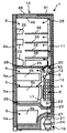
우선, 본 발명에 관한 냉장고의 전체 구조에 대해, 도 1 내지 도 6을 참조하면서 설명한다. 도 1은 본 실시예의 냉장고의 정면도이다. 도 2는 도 1에 있어서의 A-A 종단면도이다. 도 3은 냉장고의 고내의 구성을 도시하는 정면도로, 냉기 덕트나 분출구의 배치 등을 도시하는 도면이다.First, the entire structure of the refrigerator according to the present invention will be described with reference to FIGS. 1 to 6. 1 is a front view of the refrigerator of this embodiment. 2 is an A-A longitudinal cross-sectional view of FIG. 1. FIG. 3 is a front view showing the configuration of a refrigerator in a refrigerator, and shows a layout of a cold air duct, a blower outlet, and the like. FIG.
도 1에 도시한 바와 같이, 냉장고(1)의 상부로부터, 냉장실(2), 좌우에 배치된 제빙실(3) 및 상단 냉동실(4), 하단 냉동실(5), 야채실(6)을 갖는다. 냉장실(2)의 전방 개구에는 좌우로 분할된 여닫이식(프렌치 도어)인 냉장실 도어(2a, 2b)를 갖는다. 제빙실(3), 상단 냉동실(4), 하단 냉동실(5) 및 야채실(6)의 전방 개구에는 각각 인출식 제빙실 도어(3a), 상단 냉동실 도어(4a), 하단 냉동실 도어(5a) 및 야채실 도어(6a)를 구비하고 있다.As shown in FIG. 1, the
도 2에 도시한 바와 같이, 외부 상자(45)와 내부 상자(46) 사이에 발포 단열재(발포 폴리우레탄)가 충전 발포되어, 단열 상자체(10)가 형성된다. 이에 의해, 냉장고(1)의 내외는, 단열적으로 이격되어 있다. 또한, 외부 상자(45)와 내부 상자(46) 사이에는 복수의 진공 단열재(25)가 실장되어 있다. 또한, 도 2에서는 진공 단열재(25)를 냉장고(1)의 후방부에 설치하고 있지만, 상부나 바닥부에 설치함으로써, 단열 성능을 더욱 향상시킬 수 있다.As shown in FIG. 2, a foamed heat insulating material (foamed polyurethane) is filled and foamed between the
냉장실(2)과, 상단 냉동실(4) 및 제빙실(3)[도 1 참조, 도 2 중에서 제빙실(3)은 도시되어 있지 않음]은 단열 구획벽(28)에 의해 상하로 단열적으로 구획되어 있다. 또한, 단열 구획벽(28)에는 진공 단열재(25)가 설치된다. 이에 의해, 냉장 온도대인 냉장실(2)과, 냉동 온도대인 상단 냉동실(4) 및 제빙실(3)에 있어서의, 단열 성능을 향상시켜, 각 저장실의 냉각 효율을 향상시킬 수 있다. 또한, 하단 냉동실(5)과 야채실(6)은 단열 구획벽(29)에 의해 단열적으로 이격된다.The refrigerating
냉장실 도어(2a)의 고내측에는 저장 용기인 도어 포켓(32)이 상하에 복수 구비되어 있다. 또한, 냉장실(2)에는 복수의 선반(36)이 종방향으로 설치되어, 복수의 저장 스페이스로 구획되어 있다.On the inner side of the refrigerating
제빙실(3), 상단 냉동실(4), 하단 냉동실(5) 및 야채실(6)에는 제빙실 도어(3a), 상단 냉동실 도어(4a), 하단 냉동실 도어(5a) 및 야채실 도어(6a)와 각각 일체로 인출되는 수납 용기[3b(도시하지 않음), 4b, 5b, 6b]가 설치되어 있다.The
도 2 및 도 3에 도시한 바와 같이, 냉각기(7)는 하단 냉동실(5)의 후방에 설치된 냉각기실(8)에 설치된다. 냉각기(7)의 상방 투영 위치에는 고내 송풍기(9)가 설치된다. 고내 송풍기(9)에 의해, 냉각기(7)와 열교환하여 차가워진 공기(이하, 「냉기」라고 칭함)가, 냉장실 송풍 덕트(11), 야채실 송풍 덕트(14)(도 3 참조), 상단 냉동실 송풍 덕트(12), 하단 냉동실 송풍 덕트(13) 및 제빙실 송풍 덕트(도시하지 않음)를 통해, 냉장실(2), 야채실(6), 상단 냉동실(4), 하단 냉동실(5) 및 제빙실(3)로 송풍된다. 또한, 각 송풍 덕트는, 도 3에 파선으로 나타낸 바와 같이 냉장고(1)의 각 실의 후방에 설치되어 있다.As shown in FIG. 2 and FIG. 3, the
또한, 각 저장실로의 냉기의 송풍량은 냉장 온도대실 댐퍼(20), 냉동 온도대실 댐퍼(50), 야채실 댐퍼(51)의 개폐에 의해 제어된다. 냉장 온도대실 댐퍼(20)가 개방 상태인 경우, 냉각기(7)에서 열교환된 냉기는, 고내 송풍기(9)에 의해 냉장실 송풍 덕트(11)를 거쳐서 분출구(2c)로부터 각각 냉장실로 송풍된다. 냉장실(2)을 냉각한 냉기는 냉장실(2)의 후방부 하방에 형성된 복귀구(2d)로부터 냉장실 복귀 덕트(16)를 거쳐서, 냉각기실(8)의 정면에서 볼 때, 우측 하부로 복귀된다.In addition, the amount of air blown into each storage chamber is controlled by opening and closing the cold
한편, 냉동 온도대실 댐퍼(50)가 개방 상태인 경우, 제빙실 송풍 덕트(도시하지 않음), 상단 냉동실 송풍 덕트(12) 및 하단 냉동실 송풍 덕트(13)를 거쳐서, 분출구(3c, 4c, 5c)로부터 각각 제빙실(3), 상단 냉동실(4) 및 하단 냉동실(5)로 송풍된다. 제빙실(3), 상단 냉동실(4) 및 하단 냉동실(5)을 냉각한 냉기는, 하단 냉동실(5)의 후방부 하방에 형성된 냉동실 복귀구(17)를 통해, 냉각기실(8)로 복귀된다.On the other hand, when the freezing
한편, 야채실 댐퍼(51)가 개방 상태인 경우, 야채실 송풍 덕트(14)(도 3 참조)를 거쳐서, 분출구(6c)로부터 야채실(6)로 송풍된다. 야채실(6)로부터의 복귀 공기는 도시하지 않은 야채실 복귀구로부터 야채실 복귀 덕트를 거쳐서, 냉각기실(8) 좌측 하부로 복귀된다.On the other hand, when the
냉장고(1)의 하부 후방에는 기계실(19)이 설치되어 있다. 기계실(19)에는 압축기(24) 및 도 4에 도시하는 응축 수단(52), 드라이어(53), 냉매 밸브(54)가 수납되어 있고, 도시하지 않은 고외 송풍기에 의해, 압축기(24) 및 응축 수단(52)으로 통풍되어, 각각의 운전에 의해 발생한 발열을 제거한다.The
냉장고(1)의 상부 후방에는 제어 장치인 제어 기판(31)이 배치되어 있다. 제어 기판(31)에 미리 탑재된 프로그램에 의해, 압축기(24)의 온/오프 제어 및 회전 속도 제어, 냉장 온도대실 댐퍼(20), 냉동 온도대실 댐퍼(50), 야채실 댐퍼(51)의 제어, 고내 송풍기(9)의 온/오프 제어 및 회전 속도 제어, 고외 송풍기(9)의 온/오프 제어 및 회전 속도 제어 등이 행해진다.The
냉각기(7) 및 그 주변의 냉각기실(8)의 벽 등에 부착된 서리는 냉각기(7)의 하방에 설치된 제상 히터(22)에 의해 제상된다. 제상에 의해 서리가 융해되어 발생한 제상수는 냉각기실(8)의 하부에 구비된 홈(23)에 적하된 후, 배수관(27)을 통해 기계실(19)의 압축기(24)의 상방에 배치된 증발 접시(21)에 저류된다. 이에 의해, 압축기(24)나 도시하지 않은 응축기로부터의 발열과, 도시하지 않은 고외 송풍기에 의한 통풍에 의해 증발 기화된다.Frost attached to the wall of the
또한, 본 실시 형태에서는 냉매로서 이소부탄을 사용하고, 냉매 봉입량은 약 88g으로 소량으로 하고 있다.In addition, in this embodiment, isobutane is used as a refrigerant | coolant, and refrigerant | coolant sealing amount is made into a small amount about 88g.
(냉각기의 주변 구조)(Peripheral structure of cooler)
다음에, 본 실시예의 냉장고(1)의 냉각기(7)의 주변 구조에 대해, 도 4를 참조하면서 설명한다. 도 4는 냉각기(7) 주변 부분의 정면도이다. 도 5는 제상 히터의 사시도이다.Next, the peripheral structure of the
도 4 중에 화살표로 나타낸 바와 같이, 냉장실(2)로부터의 복귀 냉기는 냉장실 복귀 덕트(16)를 거쳐서, 냉각기실(8)의 정면에서 볼 때 우측 하부로 유입된다. 환언하면, 냉장실(2)로부터의 복귀 냉기는 냉각기(7)의 하방으로 유입되도록, 냉장실 복귀 덕트(16)가 설치되어 있다.As indicated by the arrow in FIG. 4, the return cooling air from the refrigerating
냉각기(7)의 좌측 상부에는 냉각기 온도 센서(18)가 구비되어 있다. 제상 운전은 제상 히터(22)에 통전[본 실시예의 제상 히터(22)의 출력은 160W]함으로써 행해진다. 또한, 제상 히터(22)는, 도 5에 도시한 바와 같이 유리관(22c)과, 유리관(22c) 내에 내장된 히터 선(도시하지 않음)과, 유리관의 외주에 접하는 일 없이 나선 형상으로 배치되는 방열 핀(22b) 및 제상수가 유리관(22c)에 적하하는 것을 방지하기 위해 설치되는 상부 커버(22a)를 갖는다. 제상 운전의 완료는 냉각기 온도 센서(18)에 의해 판정된다.The upper left side of the
또한, 야채실(6)로부터의 복귀 냉기는 도시하지 않은 야채실 복귀 덕트를 거쳐서, 냉각기실(8)의 좌측 하부 전방의 야채실 복귀 냉기 유입부(6d)로부터 냉각기실(8)로 유입된다. 환언하면, 야채실(6)로부터의 복귀 냉기는 냉각기(7)의 하방으로 유입되도록, 야채실 복귀 냉기 유입부(6d)가 설치되어 있다.Moreover, the return cold air from the
또한, 제빙실(3), 상단 냉동실(4), 하단 냉동실(5)을 냉각한 복귀 냉기는, 냉각기실(8)의 하방 전방부에 형성된 냉동실 복귀구(17)를 통해, 냉각기실(8)로 유입된다. 환언하면, 제빙실(3), 상단 냉동실(4), 하단 냉동실(5)을 냉각한 복귀 냉기는 냉각기(7)의 하방으로 유입되도록, 냉동실 복귀구(17)가 형성되어 있다.Moreover, the return chill | cooled which cooled the
[제1 실시예][First Embodiment]
다음에, 제1 실시예의 냉동 사이클에 대해, 도 6을 참조하면서 설명한다. 도 6은 냉장고의 냉매 유로를 도시한 모식도이다.Next, the refrigeration cycle of the first embodiment will be described with reference to FIG. 6. 6 is a schematic diagram illustrating a refrigerant passage of a refrigerator.
도 6에 있어서, 부호 24는 냉동 사이클 내의 냉매를 압축하는 압축기로, 도 2에 도시하는 기계실(19) 내에 설치되어, 제어 기판(31)에 의해 회전수 가변으로 제어되어 있다. 부호 52는 압축기(24)로부터 압축된 냉매를 응축하는 응축 수단이다.In FIG. 6, the code |
응축 수단(52)은 기계실(19)에 배치되어 압축기(24)에서 압축된 냉매를 응축하는 응축기(52a)와, 냉매를 응축하는 동시에 냉장고(1)의 측면의 이슬 부착을 방지하는 방열 파이프(52b)와, 냉매를 응축하는 동시에 구획부(57)의 이슬 부착을 방지하는 방열 파이프(52c)로 구성된다. 또한, 방열 파이프(52c)를 배치하는 구획부(57)는, 도 3에 도시한 바와 같이 제빙실(3) 및 상단 냉동실(4)과 하단 냉동실(5)을 상하로 구획하는 횡구획부와, 제빙실(3)과 상단 냉동실(4)을 좌우로 구획하는 종구획부로 구성된다.The condensing means 52 is arranged in the
도 6에 있어서, 부호 60은 응축 수단(52)으로 응축된 냉매를 감압하는 감압 장치(58)로의 냉매 유로를 차단하는 냉매 밸브(냉매 유로 조정 수단)이다. 부호 7은 감압 장치(58)에 의해 감압된 냉매를 증발시키는 냉각기로, 도 2에 도시되는 냉각기실(8)에 설치된다.In FIG. 6, the code |
부호 59는 냉각기(7)로부터 압축기(24)로 접속하는 흡입관이다. 압축기(24), 응축 수단(52), 냉매 밸브(60), 감압 장치(58), 냉각기(7), 흡입관(59)을 순차 접속하여 냉동 사이클을 구성한다.
다음에, 제1 실시예에 있어서의 제상 시의 제어 수단에 대해 설명한다. 도 7은 제1 실시예의 냉장고의 제상에 있어서의 압축기, 제상 히터, 냉매 밸브의 상태를 도시하는 타임차트이다. 도 7에 있어서 횡축은 시간을 나타내고, 종축은 각각 냉각기 온도 센서(18)의 온도, 압축기의 운전/정지(온/오프), 제상 히터의 통전/정지(온/오프), 냉매 밸브의 개방/폐쇄의 상태를 나타내고 있다. 도 7에 있어서, 냉각기의 온도를 나타내는 종축의 t1, t2, t3은 각각 냉각기 온도 센서(18)의 온도이고, t1은 제상 개시 시의 온도, t2는 냉각기의 상부와 하부에서 온도차가 발생했을 때의 온도, t3은 제상 종료 온도를 나타내고, t1<t2<t3의 관계가 있고, 또한 냉각기의 온도 변화는 모식적으로 나타내고 있다.Next, the control means at the time of defrosting in a 1st Example is demonstrated. Fig. 7 is a time chart showing the states of the compressor, the defrost heater, and the refrigerant valve in the defrost of the refrigerator of the first embodiment. In Fig. 7, the horizontal axis represents time, and the vertical axis represents the temperature of the
냉장고가 운전되고, 냉각기(7)에 서리가 많이 부착되어, 냉각 효율이 저하되지 않도록 제상을 행한다. 도 8에 도시하는 제상 개시 조건은 전회의 제상 종료로부터 냉장고의 적산 운전 시간을 카운트하여, 규정 시간에 도달했을 때에 제상을 개시한다. 제상 개시 조건 성립 후, 압축기(24)의 운전을 정지하고, 동시에 냉매 밸브(60)에 의해 냉매 유로를 차단함으로써 냉각기(7)로의 냉매의 유입을 방지한다.The refrigerator is operated, and defrosting is performed so that much frost is attached to the
통상 운전 시, 압축기(24)의 토출로부터 감압 장치(58)의 입구까지 고압측, 감압 장치(58) 출구로부터 흡입관(59)까지 저압측으로 운전하고 있다. 이로 인해, 압축기(24) 정지 시, 압력차를 해소하기 위해 고압측으로부터 저압측으로 냉매가 유입되려고 하지만 냉매 밸브(60)를 폐쇄로 하여 냉매 유로를 차단하기 때문에, 냉매 밸브(60)로부터 냉각기(7)까지의 냉매는 냉각기(7)로 유입되지만, 감압 장치(58)의 용량은 약간이므로, 냉각기(7)에는 냉매가 거의 유입되지 않는다.In normal operation, the pump is operated from the discharge of the
그리고, 제상 히터(22)에 통전을 개시한다. 이때, 냉각기(7)에 냉매가 유입되지 않으므로, 종래 냉각기(7)로 유입된 냉매를 따뜻하게 하는 데 이용되어 온 제상 히터(22)의 열을 냉각기(7)에 부착된 서리를 녹이는 열로 이용할 수 있어, 제상 시간을 단축할 수 있다. 또한, 냉매 밸브(60)에 의해, 냉매 유로를 차단하기 때문에, 방열 파이프(52b, 52c)의 압력은 변화되지 않고, 압력 저하에 의한 온도 저하가 없다. 이로 인해, 냉장고(1)의 측면이나 구획부(57)의 온도를 유지할 수 있어, 제상 시에 있어서의 이슬 부착을 억제할 수 있다.And electricity supply to the
그리고, 냉각기 온도 센서(18)가 소정 온도에 도달하거나, 소정 시간 이상 제상 히터(22)가 통전하면 냉매 밸브(60)를 개방으로 하여, 냉매 유로를 해방한다. 이로 인해, 냉매 밸브(60)에 의해 보유 지지하고 있던 냉매 밸브(60) 전후에서의 압력차를 해소하기 위해, 냉각기(7)로 냉매가 유입된다. 이때, 저압측의 냉각기(7)로의 냉매 유입에 의해 냉각기(7)의 압력이 상승하고, 냉각기(7)의 온도가 상승하고, 또한 냉각기(7)에 대해, 고온의 냉매 유입에 의해 냉각기(7)의 온도가 상승하므로 제상 시간을 단축할 수 있다. 또한, 냉매 유로를 차단하는 시간이 길면, 종래 냉각기(7)로 유입된 냉매를 따뜻하게 하는 데 이용되어 온 제상 히터(22)의 열을 냉각기(7)에 부착된 서리를 녹이는 열로 이용할 수 있는 시간이 길어지지만, 고온의 냉매 유입에 의한 냉각기(7)의 온도 상승은 감소한다. 서리의 융해 온도에 있어서, 냉매의 온도는 변화되지 않으므로, 서리의 융해 온도 부근에서 냉매 유로를 개방함으로써, 가장 효율적으로 제상할 수 있다.When the
그리고, 냉각기 온도 센서(18)가 제상을 종료하는 규정 온도에 도달했을 때, 제상 히터(22)의 통전을 정지하는 동시에, 압축기(24)의 운전을 재개하여, 통상의 저장실을 냉각하는 운전으로 복귀된다. 또한, 냉매 밸브(60)를 개방으로 하여, 냉매 유로를 해방하는 소정 온도 및 제상 히터 통전 시간, 제상을 종료하는 소정 온도는 압축기 용량, 봉입 냉매량, 풍로 구성, 저장실 용량 등에 따라서 다르므로, 시험 등에 의해 미리 설정한다. 또한, 제상 개시 시, 압축기(24), 냉매 밸브(54)를 동시에 동작시키고 있지만, 영향이 없는 범위에서 시간 차 및 순서가 변화되어도 좋다.When the
따라서, 제상 히터(22)의 통전량을 늘리는 일 없이, 제상 시간을 단축할 수 있어, 소비 전력량을 억제할 수 있다. 또한, 냉장고(1)의 측면이나 구획부(57)의 온도를 유지할 수 있어, 제상 시에 있어서의 이슬 부착을 억제할 수 있다.Therefore, defrost time can be shortened without increasing the electricity supply amount of the
다음에, 도 8은 제1 실시예의 제상 제어를 도시하는 플로우차트이다. 도 8에 있어서, 스텝 101은 통상의 냉각 운전의 스텝, 스텝 102는 제상 개시 조건이 성립되어 있는지 판정하는 스텝, 스텝 103은 냉매 밸브(60)를 폐쇄로 하여, 냉매 유로를 차단하는 스텝, 스텝 104는 압축기(24)를 정지시키는 스텝, 스텝 105는 제상 히터(22)에 통전을 개시하는 스텝, 스텝 106은 냉각기 온도 센서(18)가 온도 t2에 도달하였는지 판정하는 스텝, 스텝 107은 제상 히터 통전 시간이 규정 시간 Tlimit1에 도달하였는지 판정하는 스텝, 스텝 108은 냉매 밸브(60)를 개방으로 하여, 냉매 유로를 해방하는 스텝, 스텝 109는 냉각기 온도 센서(18)가 제상을 종료하는 온도 t3에 도달하였는지 판정하는 스텝, 스텝 110은 제상 히터(22)의 통전을 종료하는 스텝, 스텝 111은 압축기(24)를 재기동시키는 스텝이다.Next, FIG. 8 is a flowchart showing defrost control of the first embodiment. In Fig. 8, step 101 is a step of normal cooling operation, step 102 is a step of determining whether a defrosting start condition is established, step 103 is a step of closing the refrigerant flow path by closing the
스텝 101은 통상의 냉각 운전 스텝에서, 도시하지 않은 외기 온도 센서나 냉장 온도대실 센서, 냉동 온도대실 센서, 야채실 센서 등에 의해 검출된 냉장고(1)의 상태에 기초하여 압축기(24)나 고내 송풍기(9)의 온/오프 및 냉장 온도대실 댐퍼(20), 냉동 온도대실 댐퍼(50), 야채실 댐퍼(51)의 개폐 등에 의해, 각 저장실의 온도를 제어하는 통상의 냉각 운전을 행한다.Step 101 is based on the condition of the
스텝 102는 제상 개시 조건이 성립되어 있는지 판정하는 스텝으로, 전회의 제상 종료로부터 냉장고의 적산 운전 시간을 카운트하여, 소정 시간에 도달했을 때 제상 개시 조건이 성립된 것으로 한다. 제상 개방 시 조건이 성립되어 있지 않았던 경우, 스텝 101로 돌아가 통상의 냉각 운전을 행하고, 다시 스텝 102에서 제상 개시 조건을 판정한다. 제상 개시 조건이 성립된 경우, 스텝 103에서 냉매 밸브(60)를 폐쇄로 하여 냉매 유로를 차단하고, 스텝 104에서 압축기(24)의 운전을 정지한다. 또한, 냉장고의 적산 운전 시간은 도어의 개폐 횟수나 시간, 외기온 등에 따라서 적산량이 다르다.Step 102 is a step for determining whether the defrosting start condition is established. The integration operation time of the refrigerator is counted from the end of the last defrosting, and the defrosting start condition is established when the predetermined time is reached. If the condition at the time of defrosting has not been established, the flow returns to step 101 to perform normal cooling operation, and the defrosting start condition is determined again in step 102. When the defrosting start condition is established, the
그리고, 스텝 105에서 제상 히터(22)에 통전을 개시하여, 냉각기(7)에 부착된 서리를 녹인다. 스텝 106은 냉각기 온도 센서(18)가 소정 온도 t2에 도달하였는지 판정하는 스텝으로, 냉각기 온도 센서(18)가 소정 온도 t2에 도달한 경우, 스텝 108에서 냉매 밸브(60)를 개방으로 하여, 냉매 유로를 해방한다. 또한, 냉각기 온도 센서(18)가 소정 온도 t2에 도달하지 않았던 경우, 스텝 107에서 제상 히터 통전 시간 Tlimit1에 도달하였는지 판정하여, 제상 히터 통전 시간이 Tlimit1에 도달한 경우, 스텝 108에서 냉매 밸브(60)를 개방으로 하여, 냉매 유로를 해방한다. 또한, 제상 히터 통전 시간이 Tlimit1에 도달하지 않았던 경우, 스텝 106으로 돌아가 냉각기 온도 센서(18)가 소정 온도 t2에 도달하였는지 판정한다.Then, electricity is supplied to the
그리고, 스텝 109에서 냉각기 온도 센서(18)가 제상을 종료하는 소정 온도 t3에 도달하였는지 판정하여, 도달하고 있지 않으면, 스텝 109에서 소정 온도 t3에 도달하였는지 반복해서 판정한다. 소정 온도 t3에 도달한 경우, 스텝 110에서 제상 히터의 통전을 종료하고, 스텝 111에서 압축기를 재기동시키고, 스텝 101에서 통상의 냉각 운전으로 복귀된다.And in step 109, it is determined whether the
또한, 스텝 103, 스텝 104, 스텝 105는 동시여도 좋고, 영향이 없는 시간 차로 순서가 바뀌어도 좋다. 또한, 스텝 106, 스텝 107은 순서가 바뀌어도 좋다.In addition, step 103, step 104, and step 105 may be simultaneous, and the order may be changed with the time difference which does not affect. In addition, the order may be changed in step 106 and step 107.
이와 같이, 압축기(24)를 정지시키는 스텝과 냉매 밸브(60)를 폐쇄로 하여, 냉매 유로를 차단하는 스텝을 구비한 것에 의해, 냉각기(7)로 냉매가 유입되지 않고, 종래 냉각기(7)로 유입된 냉매를 따뜻하게 하는 데 이용되어 온 제상 히터의 열을 냉각기(7)에 부착된 서리를 녹이는 열로 이용할 수 있고, 스텝 108에서 냉매 밸브(60)를 개방으로 하여, 냉매 유로를 해방함으로써, 냉매가 냉각기(7)로 유입되어, 냉각기(7)의 압력이 상승하고, 냉각기(7)의 온도가 상승하고, 또한 냉각기(7)에 대해, 고온의 냉매 유입에 의해 냉각기(7)의 온도가 상승한다. 따라서, 제상 히터(22)의 통전량을 늘리는 일 없이, 제상 시간을 단축할 수 있어, 소비 전력량을 억제할 수 있다.In this way, the step of stopping the
[제2 실시예][Second Embodiment]
다음에, 제2 실시예의 냉동 사이클에 대해, 도 9를 참조하면서 설명한다. 도 9는 냉장고의 냉매 유로를 도시한 모식도이다.Next, the refrigeration cycle of the second embodiment will be described with reference to FIG. 9. 9 is a schematic diagram illustrating a refrigerant passage of a refrigerator.
부호 55는 방열 파이프(52b)와 감압 장치(58)를 연결하는 단락 파이프(제2 냉매 유로)이다. 부호 54는 방열 파이프(52c)(제1 냉매 유로)와 단락 파이프(55)(제2 냉매 유로)를 차단 또는 전환하는 냉매 밸브(제1 냉매 유로 조정 수단)이다. 부호 56은 방열 파이프(52c)와 단락 파이프(55)의 냉매 유로 사이에서 냉매의 왕래를 방지하기 위해, 냉매 유로 출구[방열 파이프(52c)(제1 냉매 유로)의 출구]에 설치한 역지 밸브이다. 그 밖의 부호는 제1 실시예와 동일하므로 동일한 부호를 부여하여 설명을 생략한다.
제2 실시예에 있어서의 제상 시의 제어 수단에 대해 설명한다. 도 10은 제2 실시예의 제어를 도시하는 냉장고의 제상에 있어서의 압축기, 제상 히터, 냉매 밸브의 상태를 도시하는 타임차트이다. 도 10에 있어서 횡축은 시간을 나타내고, 종축은 각각 냉각기 온도 센서(18)의 온도, 압축기의 운전/정지(온/오프), 제상 히터의 통전/정지(온/오프), 냉매 밸브의 방열 파이프(52c)(제1 냉매 유로)측, 단락 파이프(55)(제2 냉매 유로)측, 완전 폐쇄의 상태를 나타내고 있다. 도면에 있어서, 냉각기의 온도를 나타내는 종축의 t1, t2, t3은 제1 실시예의 그것과 동일하므로 설명을 생략한다.The control means at the time of defrosting in a 2nd Example is demonstrated. FIG. 10 is a time chart showing the states of the compressor, the defrost heater, and the refrigerant valve in the defrost of the refrigerator showing control of the second embodiment. In Fig. 10, the horizontal axis represents time, and the vertical axis represents the temperature of the
냉장고가 운전되어, 냉각기(7)에 서리가 많이 부착되어, 냉각 효율이 저하되지 않도록 제상을 행한다. 도 10에 도시하는 제상 개시 조건은 전회의 제상 종료로부터 냉장고의 적산 운전 시간을 카운트하여, 소정 시간에 도달했을 때에 제상을 개시한다. 제상 개시 조건 성립 후, 냉매 밸브(54)에 의해 냉매 유로를 차단하여, 일정 시간 경과 후 압축기(24)의 운전을 정지하고, 방열 파이프(52c), 단락 파이프(55), 냉각기(7)에 존재하는 냉매를 모두 또는 일정량 제거한다.The refrigerator is operated, and a lot of frost is attached to the
냉매 밸브(54)에 의해 냉매 유로를 차단해도, 압축기(24)를 운전하므로, 냉매 밸브(54)로부터 흡입관(59)까지 저압측의 냉매는 압축기(24)의 토출로부터 냉매 밸브(54)까지의 고압측으로 모인다. 이로 인해, 일정 시간 경과 후, 압축기(24)를 정지함으로써, 냉각기(7)에 남은 냉매를 조정할 수 있다. 또한, 냉매 유로 차단으로부터 압축기(24) 정지까지의 시간이 짧은 경우, 혹은 제1 실시예와 같이 압축기 정지와 함께 냉매 유로를 차단한 경우, 방열 파이프(52c) 및 단락 파이프(55)의 냉매가 냉각기(7)로 유입된다.Even if the refrigerant passage is blocked by the
냉매 유로를 차단한 것에 의한 효과는 제1 실시예와 마찬가지이므로 설명을 생략한다.Since the effect by blocking the coolant flow path is the same as in the first embodiment, the description is omitted.
그리고, 냉각기 온도 센서(18)가 소정 온도에 도달하거나, 소정 시간 이상 제상 히터(22)가 통전되면 냉매 밸브(54)를 단락 파이프(55)측 개방으로 하여, 단락 파이프(55)를 해방한다. 이로 인해, 냉매 밸브(54)에 의해 보유 지지하고 있던 냉매 밸브(54) 전후에서의 압력차를 해소하기 위해, 냉각기(7)로 냉매가 유입된다. 이때, 저압측의 냉각기(7)로의 냉매 유입에 의해 냉각기(7)의 압력이 상승하고, 온도가 상승하고, 또한 냉각기(7)에 대해 고온의 냉매 유입에 의해 냉각기(7)의 온도가 상승하므로 제상 시간을 단축할 수 있다. 또한, 방열 파이프(52c)를 통과하지 않으므로, 고내로의 열 침입을 방지할 수 있어, 고내의 열에 의해 냉매가 차가워지지 않으므로, 고온의 상태로 냉매를 냉각기(7)로 유입시킬 수 있다.When the
그리고, 냉각기 온도 센서(18)가 제상을 종료하는 규정 온도에 도달했을 때, 제상 히터(22)의 통전을 정지하는 동시에, 냉매 밸브(54)를 방열 파이프(52c)측 개방으로 하여, 압축기(24)의 운전을 재개하고, 통상의 저장실을 냉각하는 운전으로 복귀된다. 또한, 제상 개시 시, 압축기(24), 제상 히터(22), 냉매 밸브(54)를 동시에 동작시키고 있지만, 영향이 없는 범위에서 시간 차 및 순서가 변화되어도 좋다.When the
따라서, 제상 히터(22)의 통전량을 늘리는 일 없이, 제상 시간을 단축할 수 있고, 제상 시의 저장실로의 열 침입을 억제함으로써 제상 후의 저장실의 냉각을 단축할 수 있어, 소비 전력량을 억제할 수 있다. 또한, 냉장고(1)의 측면이나 구획부(57)의 온도를 유지할 수 있어, 제상 시에 있어서의 이슬 부착을 억제할 수 있다.Therefore, the defrost time can be shortened without increasing the amount of energization of the
도 11은 제2 실시예의 제상 제어를 도시하는 플로우차트이다. 도 11에 있어서, 스텝 212는 냉매 밸브(54)를 완전 폐쇄로 하여 냉매 유로를 차단하는 스텝, 스텝 213은 냉매 밸브(54)를 완전 폐쇄로 하여, 냉매 유로를 차단한 후의 시간이 냉각기(7)에 남은 냉매를 제거하는 소정 시간 Tlimit2에 도달하고 있는지 판정하는 스텝, 스텝 214는 냉매 밸브를 단락 파이프(55)측 개방으로 하여, 단락 파이프(55)만 냉매 유로를 해방하는 스텝, 스텝 215는 냉매 밸브(54)를 방열 파이프(52c)측 개방으로 하는 스텝이다. 스텝 201 내지 스텝 211은 제1 실시예의 스텝 101 내지 스텝 111과 동일하므로 설명을 생략한다.11 is a flowchart showing the defrost control of the second embodiment. In FIG. 11, step 212 is a step of shutting off the coolant flow path with the
제상 개시 조건이 성립된 경우, 스텝 212에서 냉매 밸브(54)를 완전 폐쇄로 하여, 냉매 유로를 차단한다. 스텝 213은 냉매 밸브(54)를 완전 폐쇄로 하여, 냉매 유로를 차단한 후의 시간이 냉각기(7)에 남은 냉매를 제거하는 소정 시간 Tlimit2에 도달하고 있는지 판정하는 스텝으로, 냉매 유로를 차단한 후의 시간이 소정 시간 Tlimit2에 도달하고 있지 않으면, 스텝 204에서 소정 시간 Tlimit2에 도달하고 있는지 판정을 반복한다. 소정 시간 Tlimit2에 도달하고 있으면, 스텝 205에서 압축기(24)의 운전을 정지한다.When the defrosting start condition is established, the
그리고, 스텝 206에서 냉각기 온도 센서(18)가 소정 온도 t2에 도달하거나, 스텝 207에서 제상 히터 통전 시간이 Tlimit1에 도달한 경우, 스텝 214에서 냉매 밸브(54)를 단락 파이프(55)측 개방으로 하여, 단락 파이프(55)만 냉매 유로를 해방한다.Then, when the
그리고, 스텝 209에서 냉각기 온도 센서(18)가 소정 온도 t3에 도달한 경우, 스텝 215에서 냉매 밸브(54)를 방열 파이프(52c)측 개방으로 한다.When the
이와 같이, 냉각기(7)에 남은 냉매를 제거하는 규정 시간 Tlimit2에 도달하고 있는지 판정하는 스텝을 구비한 것에 의해, 냉각기(7)에 남은 냉매량을 조정할 수 있다. 또한, 단락 파이프(55)만 냉매 유로를 해방하는 스텝을 구비한 것에 의해, 방열 파이프(52c)를 통과하지 않으므로, 고내로의 열 침입을 방지할 수 있어, 고내의 열에 의해 냉매가 차가워지지 않으므로, 고온의 상태로 냉매를 냉각기(7)로 유입시킬 수 있다. 따라서, 제상 히터의 통전량을 늘리는 일 없이, 제상 시간을 단축할 수 있어, 소비 전력량을 억제할 수 있다.Thus, by providing the step of determining whether the prescribed time Tlimit2 for removing the coolant remaining in the
[제3 실시예]Third Embodiment
다음에, 제3 실시예의 냉동 사이클에 대해, 도 12를 참조하면서 설명한다.Next, the refrigeration cycle of the third embodiment will be described with reference to FIG.
도 12에 있어서, 부호 54a는 방열 파이프(52c)와 단락 파이프(55)를 차단 및 전환하는 냉매 밸브(제1 냉매 유로 조정 수단)이고, 부호 54b는 응축 수단으로 응축된 냉매를 감압하는 감압 장치(58)로의 냉매 유로를 차단하는 냉매 밸브(제2 냉매 유로 조정 수단)이다. 그 밖의 부호는 제1 실시예와 마찬가지이므로 설명을 생략한다.In Fig. 12,
제3 실시예에 있어서의 제상 시 제어 수단에 대해 설명한다. 도 13은 제3 실시예의 제어를 도시하는 냉장고의 제상에 있어서의 압축기, 제상 히터, 제1 냉매 유로 조정 수단, 제2 냉매 유로 조정 수단의 상태를 도시하는 타임차트이다. 도 13에 있어서 횡축은 시간을 나타내고, 종축은 각각 냉각기 온도 센서(18)의 온도, 압축기의 운전/정지(온/오프), 제상 히터의 통전/정지(온/오프), 냉매 밸브(54a)의 방열 파이프(52c)측, 단락 파이프(55)측, 완전 폐쇄의 상태, 냉매 밸브(54b)의 개방/폐쇄의 상태를 나타내고 있다. 도면에 있어서, 냉각기의 온도를 나타내는 종축의 t1, t2, t3은 제1 실시예의 그것과 마찬가지이므로 설명을 생략한다.The control means at the time of defrosting in the third embodiment will be described. FIG. 13 is a time chart showing the states of the compressor, the defrost heater, the first refrigerant passage adjusting means, and the second refrigerant passage adjusting means in the defrost of the refrigerator showing control of the third embodiment. In Fig. 13, the horizontal axis represents time, and the vertical axis represents the temperature of the
도 13에 있어서, 제상 개시 조건 성립 후, 압축기(24)의 운전을 정지하고, 동시에 냉매 밸브(54a), 냉매 밸브(54b)를 완전 폐쇄로 함으로써 냉매 유로를 차단하는 것에 의해 냉각기(7)로의 냉매의 유입을 방지한다.In Fig. 13, after the defrosting start condition is established, the operation of the
통상 운전 시, 압축기(24)의 토출로부터 감압 장치(58)의 입구까지 고압측, 감압 장치(58) 출구로부터 흡입관(59)까지 저압측으로 운전하고 있다. 이로 인해, 압축기(24) 정지 시, 압력차를 해소하기 위해 고압측으로부터 저압측으로 냉매가 유입되려고 하지만, 냉매 밸브(54a), 냉매 밸브(54b)를 완전 폐쇄로 하여, 냉매 유로를 차단하기 때문에, 냉매 밸브(54b)로부터 냉각기(7)까지의 냉매는 냉각기(7)로 유입되지만, 감압 장치(58)의 용량은 약간이므로, 냉각기(7)로는 냉매가 거의 유입되지 않는다. 또한, 냉매 밸브(54a)를 완전 폐쇄로 하므로, 방열 파이프(52c)로부터 냉매가 유출되지 않아, 냉매를 고온의 상태로 응축기(52a), 방열 파이프(52b)에 유지할 수 있다.In normal operation, the pump is operated from the discharge of the
냉매 유로를 차단한 것에 의한 효과는 제1 실시예와 동일하므로 설명을 생략한다.Since the effect by blocking the coolant flow path is the same as in the first embodiment, the description is omitted.
그리고, 냉각기 온도 센서(18)가 소정 온도에 도달하거나, 소정 시간 이상 제상 히터(22)가 통전하면, 냉매 밸브(54a)를 단락 파이프(55)측 개방, 냉매 밸브(54b)를 개방으로 하여, 냉매 유로를 해방한다. 이로 인해, 냉매 밸브(54b)에 의해 보유 지지하고 있던 냉매 밸브(54b) 전후에서의 압력차를 해소하기 위해, 냉각기(7)로 냉매가 유입된다. 이후, 제2 실시예와 마찬가지이므로 설명을 생략한다. 또한, 제상 개시 시, 압축기(24), 제상 히터(22), 냉매 밸브(54a), 냉매 밸브(54b)를 동시에 동작시키고 있지만, 영향이 없는 범위에서 시간 차 및 순서가 변화되어도 좋다.When the
따라서, 제상 히터의 통전량을 늘리는 일 없이, 제상 시간을 단축할 수 있고, 제상 시의 저장실로의 열 침입을 억제함으로써 제상 후의 저장실의 냉각을 단축할 수 있어, 소비 전력량을 억제할 수 있다. 또한, 냉장고(1)의 측면이나 구획부(57)의 온도를 유지할 수 있어, 제상 시에 있어서의 이슬 부착을 억제할 수 있다.Therefore, the defrost time can be shortened without increasing the amount of electricity supplied to the defrost heater, and the cooling of the storage chamber after defrosting can be shortened by suppressing heat ingress into the storage chamber during defrosting, and the power consumption can be suppressed. Moreover, the temperature of the side surface and the partition part 57 of the
도 14는 제3 실시예의 제상 제어를 도시하는 플로우차트이다. 도면에 있어서, 스텝 316은 스텝 312에서 냉매 밸브(54a)를 완전 폐쇄로 한 동시에, 냉매 밸브(54b)를 폐쇄로 하여, 감압 장치(58)로의 냉매 유로를 차단하는 스텝이다. 스텝 317은 스텝 314에서 냉매 밸브(54a)를 단락 파이프(55)측 개방으로 하는 동시에 냉매 밸브(54b)를 개방으로 하여, 감압 장치(58)로의 냉매 유로를 개방하는 스텝이다. 스텝 301 내지 스텝 315는 제1 실시예의 스텝 201 내지 스텝 215와 마찬가지이므로 설명을 생략한다.14 is a flowchart showing the defrost control in the third embodiment. In the figure, step 316 is a step of closing the refrigerant flow path to the
스텝 302에서 제상 개시 조건이 성립된 경우, 스텝 312에서 냉매 밸브(54a)를 완전 폐쇄로 한 동시에, 냉매 밸브(54b)를 폐쇄로 하여, 감압 장치(58)로의 냉매 유로를 차단한다. 스텝 314에서 냉매 밸브(54a)를 단락 파이프(55)측 개방으로 하여, 단락 파이프(55)만 냉매 유로를 해방한 동시에 냉매 밸브(54b)를 개방으로 하여, 감압 장치(58)로의 냉매 유로를 개방한다. 또한, 스텝 312와 스텝 316, 스텝 314와 스텝 317은 동시여도 좋고, 영향이 없는 시간 차로 순서가 바뀌어도 좋다.When the defrosting start condition is established in step 302, the
이와 같이, 냉매 밸브(54a)를 완전 폐쇄로 한 동시에, 냉매 밸브(54b)를 폐쇄로 하여, 감압 장치(58) 및 냉각기(7)로의 냉매 유로를 차단하는 스텝과, 냉매 밸브(54a)를 단락 파이프(55)측 개방으로 한 동시에 냉매 밸브(54b)를 개방으로 하여, 감압 장치(58) 및 냉각기(7)로의 냉매 유로를 개방하는 스텝을 구비함으로써, 제2 실시예와 동일한 효과를 얻을 수 있다.In this manner, the
[제4 실시예][Fourth Embodiment]
다음에, 제4 실시예의 냉동 사이클에 대해, 도 15를 참조하면서 설명한다. 도 15에 있어서, 부호 54c는 응축기에서 응축된 냉매를 감압하는 감압 장치(58)로의 냉매 유로를 차단하여, 방열 파이프(52c)와 단락 파이프(55)의 냉매 유로 사이에서 냉매의 왕래를 방지하는 냉매 밸브(2방향 밸브)이다. 그 밖의 부호는 제1 실시예와 마찬가지이므로 설명을 생략한다.Next, the refrigeration cycle of the fourth embodiment will be described with reference to FIG. 15. In Fig. 15,
제4 실시예에 있어서의 제상 시 제어 수단에 대해 설명한다. 압축기, 제상 히터, 냉매 밸브(54a), 냉매 밸브(54c)[제2 실시예에서는 역지 밸브(56)]의 제어에 대해서는 제2 실시예와 마찬가지이므로 설명을 생략한다.The control means at the time of defrosting in the fourth embodiment will be described. Since the control of the compressor, the defrost heater, the
통상 운전 시, 압축기(24)의 토출로부터 감압 장치(58)의 입구까지 고압측, 감압 장치(58) 출구로부터 흡입관(59)까지 저압측으로 운전하고 있다. 이로 인해, 압축기(24) 정지 시, 압력차를 해소하기 위해 고압측으로부터 저압측으로 냉매가 유입되려고 하지만, 냉매 밸브(54a), 냉매 밸브(54c)를 완전 폐쇄로 하여, 냉매 유로를 차단하기 때문에, 단락 파이프(55)의 냉매 유로 및 냉매 밸브(54c)로부터 냉각기(7)까지의 냉매는 냉각기(7)로 유입되지만, 단락 파이프(55)의 용량은 방열 파이프(52c)에 비해 약간이고, 감압 장치(58)의 용량은 약간이므로 냉각기(7)에는 소량의 냉매밖에 유입되지 않는다. 또한, 냉매 밸브(54a)를 완전 폐쇄로 하므로, 방열 파이프(52c)로 냉매가 유입되지 않아, 냉매를 고온의 상태로 응축기(52a), 방열 파이프(52b)에 유지할 수 있다. 또한, 제2 실시예와 같이 압축기 정지 전에, 냉매 밸브(54a), 냉매 밸브(54c)를 완전 폐쇄로 함으로써, 냉각기(7)로 유입되는 냉매량을 조정해도 좋다. 그 밖의 제어 및 효과에 관해서는 제2 실시예와 마찬가지이므로 설명을 생략한다.In normal operation, the pump is operated from the discharge of the
[제5 실시예][Fifth Embodiment]
다음에, 제5 실시예의 냉동 사이클에 대해, 도 16을 참조하면서 설명한다. 도 16에 있어서, 부호 61은 방열 파이프(52c) 입구와 출구, 방열 파이프(52b) 출구, 감압 장치(58)의 접속을 전환할 수 있는 냉매 밸브(냉매 유로 조정 수단)이다. 그 밖의 부호는 제1 실시예와 마찬가지이므로 설명을 생략한다.Next, the refrigeration cycle of the fifth embodiment will be described with reference to FIG. In Fig. 16,
제5 실시예에 있어서의 제상 시 제어 수단에 대해 설명한다. 도 17은 제5 실시예의 제어를 도시하는 냉장고의 제상에 있어서의 압축기, 제상 히터, 냉매 밸브(61)의 상태를 도시하는 타임차트이다. 도 16에 있어서 횡축은 시간을 나타내고, 종축은 각각 냉각기 온도 센서(18)의 온도, 압축기의 운전/정지(온/오프), 제상 히터의 통전/정지(온/오프), 냉매 밸브(61)의 방열 파이프(52b) 출구와 방열 파이프(52c) 입구를 연결하고, 방열 파이프(52c) 출구와 감압 장치를 연결하는 A-B측, 방열 파이프(52c) 입구와 출구를 연결하고, 방열 파이프(52b) 출구와 감압 장치를 연결하는 A-C측, 완전 폐쇄의 상태를 나타내고 있다. 도면에 있어서, 냉각기의 온도를 나타내는 종축의 t1, t2, t3은 제1 실시예의 그것과 동일하므로 설명을 생략한다.The control means at the time of defrosting in the fifth embodiment will be described. FIG. 17 is a time chart showing the states of the compressor, the defrost heater, and the
도 16에 있어서, 제상 개시 조건 성립 후, 압축기(24)의 운전을 정지하고, 동시에 냉매 밸브(61)를 완전 폐쇄로 함으로써 냉매 유로를 차단하는 것에 의해 냉각기(7)로의 냉매의 유입을 방지한다.In FIG. 16, after the defrosting start condition is established, the
냉매 유로를 차단한 것에 의한 효과는 제1 실시예와 마찬가지이므로 설명을 생략한다.Since the effect by blocking the coolant flow path is the same as in the first embodiment, the description is omitted.
그리고, 냉각기 온도 센서(18)가 소정 온도에 도달하거나, 소정 시간 이상 제상 히터(22)가 통전하면, 냉매 밸브(61)를 A-C측 개방으로 하여, 냉매 유로를 해방한다. 이로 인해, 냉매 밸브(61)에 의해 보유 지지되어 있던 냉매 밸브(61) 전후에서의 압력차를 해소하기 위해, 냉각기(7)로 냉매가 유입된다. 냉매가 유입되는 것에 의한 효과는 제2 실시예와 마찬가지이므로 설명을 생략한다.When the
그리고, 냉각기 온도 센서(18)가 제상을 종료하는 소정 온도에 도달했을 때, 제상 히터(22)의 통전을 정지하는 동시에, 냉매 밸브(61)를 A-B측 개방으로 하여, 압축기(24)의 운전을 재개하고, 통상의 저장실을 냉각하는 운전으로 복귀된다. 또한, 제상 개시 시, 압축기(24), 제상 히터(22), 냉매 밸브(61)를 동시에 동작시키고 있지만, 영향이 없는 범위에서 시간 차 및 순서가 변화되어도 좋다. 이후, 제2 실시예와 마찬가지이므로 설명을 생략한다.When the
따라서, 제상 히터의 통전량을 늘리는 일 없이, 제상 시간을 단축할 수 있고, 제상 시의 저장실로의 열 침입을 억제함으로써 제상 후의 저장실의 냉각을 단축할 수 있어, 소비 전력량을 억제할 수 있다. 또한, 냉장고(1)의 측면이나 구획부(57)의 온도를 유지할 수 있어, 제상 시에 있어서의 이슬 부착을 억제할 수 있다.Therefore, the defrost time can be shortened without increasing the amount of electricity supplied to the defrost heater, and the cooling of the storage chamber after defrosting can be shortened by suppressing heat ingress into the storage chamber during defrosting, and the power consumption can be suppressed. Moreover, the temperature of the side surface and the partition part 57 of the
도 18은 제5 실시예의 제상 제어를 도시하는 플로우차트이다. 도면에 있어서, 스텝 512는 냉매 밸브(61)를 완전 폐쇄로 하여, 감압 장치(58)로의 냉매 유로를 차단하는 스텝이다. 스텝 514는 냉매 밸브(54)를 A-C측 개방으로 하여, 감압 장치(58)로의 냉매 유로를 개방하는 스텝이다. 스텝 515는 냉매 밸브(54)를 A-B측 개방으로 하여, 방열 파이프(52c)의 냉매 유로를 개방하는 스텝이다. 스텝 501 내지 스텝 511은 제1 실시예의 스텝 101 내지 스텝 111과 마찬가지이므로 설명을 생략한다.18 is a flowchart showing the defrost control in the fifth embodiment. In the figure, step 512 is a step of closing the refrigerant flow path to the
[제6 실시예][Sixth Embodiment]
다음에, 제6 실시예에 대해 설명한다. 또한, 제6 실시예의 냉동 사이클은 제2 실시예와 마찬가지이므로 설명을 생략한다.Next, a sixth embodiment will be described. In addition, since the refrigeration cycle of the sixth embodiment is the same as in the second embodiment, description thereof is omitted.
우선, 제6 실시예의 냉장고의 제상 시 제어 수단에 대해 설명한다. 도 19는 제6 실시예의 제어를 도시하는 실시예의 냉장고의 제상에 있어서의 압축기, 제상 히터, 고내 송풍기, 냉장 온도대실 댐퍼, 냉동 온도대실 댐퍼, 냉매 밸브의 상태를 도시하는 타임차트이다.First, the control means at the time of defrosting the refrigerator of the sixth embodiment will be described. 19 is a time chart showing the states of a compressor, a defrost heater, an internal blower, a refrigeration temperature chamber damper, a refrigeration temperature chamber damper, and a refrigerant valve in the defrost of the refrigerator of the embodiment showing control of the sixth embodiment.
도 19에 있어서 횡축은 시간을 나타내고, 종축은 각각 냉각기 온도 센서(18)의 온도, 압축기의 운전/정지(온/오프), 제상 히터의 통전/정지(온/오프), 고내 송풍기의 통전 온/오프, 냉장 온도대실 댐퍼의 개방/폐쇄, 냉동 온도대실 댐퍼의 개방/폐쇄, 냉매 밸브(54)의 방열 파이프(52c)측, 단락 파이프(55)측, 완전 폐쇄의 상태를 나타내고 있다. 도면에 있어서, 냉각기의 온도를 나타내는 종축의 t1, t2, t3은 제1 실시예의 그것과 마찬가지이므로 설명을 생략한다. 또한, 압축기 정지까지는 제2 실시예와 마찬가지이므로 설명을 생략한다.In Fig. 19, the horizontal axis represents time, and the vertical axis represents the temperature of the
압축기 정지 후, 고내 송풍기(9)에 통전되어 있는 상태에서, 냉동 온도대실 댐퍼(50)를 폐쇄, 냉장 온도대실 댐퍼(20)를 개방으로 하여, 제상 히터(22)에 통전을 개시한다. 이때, 고내 송풍기(9)에 통전되어 있는 상태에서, 냉장 온도대실 댐퍼(20)가 개방되어 있으므로, 냉각기(7)에 부착된 서리를 녹이면서, 냉각기(7)에 부착된 서리를 이용하여 냉장실(2)을 냉각할 수 있다. 냉매 제어에 의한 효과는 제2 실시예와 마찬가지이므로 설명을 생략한다.After the compressor is stopped, the refrigeration
그리고, 냉각기 온도 센서(18)가 소정 온도에 도달하거나, 소정 시간 이상 제상 히터(22)가 통전되면 고내 송풍기(9)에 통전을 정지하고, 냉동 온도대실 댐퍼(50)를 개방, 냉장 온도대실 댐퍼(20)를 폐쇄로 하고, 냉매 밸브(54)를 단락 파이프(55)측 개방으로 하여, 냉매 유로를 해방한다. 냉매가 유입되는 것에 의한 효과는 제2 실시예와 마찬가지이므로 설명을 생략한다.Then, when the
그리고, 냉각기 온도 센서(18)가 제상을 종료하는 규정 온도에 도달했을 때, 제상 히터(22)의 통전을 정지하는 동시에, 냉매 밸브(54)를 방열 파이프(52c)측 개방으로 하고, 냉동 온도대실 댐퍼(50)를 폐쇄, 냉장 온도대실 댐퍼를 개방, 고내 송풍기에 통전을 개시하여, 압축기(24)의 운전을 재개하고, 통상의 저장실을 냉각하는 운전으로 복귀된다. 또한, 제상 개시 시, 압축기(24), 냉매 밸브(54), 냉장 온도대실 댐퍼(20), 냉동 온도대실 댐퍼(50), 제상 히터를 동시에 동작시키고 있지만, 영향이 없는 범위에서 시간 차 및 순서가 변화되어도 좋다.When the
따라서, 제상 히터의 통전량을 늘리는 일 없이, 제상 시간을 단축할 수 있고, 또한 제상 시의 냉장실(2)을 냉각할 수 있으므로, 소비 전력량을 억제할 수 있다. 또한, 냉장고(1)의 측면이나 구획부(57)의 온도를 유지할 수 있어, 제상 시에 있어서의 이슬 부착을 억제할 수 있다.Therefore, since the defrost time can be shortened and the
도 20은 제6 실시예의 제상 제어를 도시하는 플로우차트이다. 도면에 있어서, 스텝 616은 냉동 온도대실 댐퍼(50)를 폐쇄로 하는 스텝, 스텝 617은 냉장 온도대실 댐퍼(20)를 개방으로 하는 스텝, 스텝 618은 고내 송풍기(9)를 정지하는 스텝, 스텝 619는 냉장 온도대실 댐퍼(20)를 폐쇄로 하는 스텝, 스텝 620은 냉동 온도대실 댐퍼(50)를 개방으로 하는 스텝, 스텝 621은 냉동 온도대실 댐퍼(50)를 폐쇄로 하는 스텝, 스텝 622는 냉장 온도대실 댐퍼(20)를 개방으로 하는 스텝, 스텝 623은 고내 송풍기(9)의 통전을 재개하는 스텝이다. 스텝 601 내지 스텝 615는 제1 실시예의 스텝 201 내지 스텝 215와 마찬가지이므로 설명을 생략한다.20 is a flowchart showing defrost control of the sixth embodiment. In the figure, step 616 is a step of closing the refrigeration
스텝 604에서 압축기를 정지한 후, 스텝 616에서 냉동 온도대실 댐퍼(50)를 폐쇄로 하고, 스텝 617에서 냉장 온도대실 댐퍼(20)를 개방으로 한다. 이때, 고내 송풍기(9)에 통전되어 있으므로, 냉각기(7)에 부착된 서리를 녹이면서, 냉각기(7)에 부착된 서리를 이용하여 냉장실(2)을 냉각할 수 있다.After stopping the compressor in step 604, the refrigeration
또한, 스텝 614에서 냉매 밸브(54)를 단락 파이프(55)측 개방으로 한 후, 스텝 618에서 고내 송풍기를 정지하고, 스텝 619에서 냉장 온도대실 댐퍼(20)를 폐쇄로 하고, 스텝 620에서 냉동 온도대실 댐퍼(50)를 개방으로 한다.In addition, after opening the refrigerant |
또한, 스텝 610에서 제상 히터 통전 정지 후, 스텝 621에서 냉동 온도대실 댐퍼(50)를 폐쇄로 하고, 스텝 622에서 냉장 온도대실 댐퍼(20)를 개방으로 하고, 스텝 623에서 고내 송풍기(9)의 통전을 재개한다. 또한, 스텝 604, 스텝 616, 스텝 617, 스텝 605는 동시여도 좋고, 영향이 없는 시간 차로 순서가 바뀌어도 좋다. 스텝 618 내지 스텝 620도 마찬가지이다. 스텝 610, 스텝 615, 스텝 611, 스텝 621 내지 스텝 623도 마찬가지이다.After the defrost heater energization stops in step 610, the refrigeration
이와 같이, 고내 송풍기의 통전, 냉장 온도대실 댐퍼(20)의 개폐, 냉동 온도대실 댐퍼(50)의 개폐를 구비한 것에 의해, 제상 시의 냉장실(2)을 냉각할 수 있다. 냉매 제어에 의한 효과는 제2 실시예와 마찬가지이므로 설명을 생략한다. 따라서, 제상 히터의 통전량을 늘리는 일 없이, 제상 시간을 단축할 수 있어, 소비 전력량을 억제할 수 있다.Thus, the
7 : 냉각기
9 : 고내 팬(고내 송풍기)
18 : 냉각기 온도 센서
20 : 냉장 온도대실 댐퍼
22 : 제상 히터(가열 수단)
24 : 압축기
50 : 냉동 온도대실 댐퍼
52 : 응축 수단
52a : 응축기
52b : 방열 파이프
52c : 방열 파이프(제1 냉매 유로)
54, 54a : 냉매 밸브(3방향 밸브, 제1 냉매 유로 조정 수단)
54b : 냉매 밸브(2방향 밸브, 제2 냉매 유로 조정 수단)
54c : 냉매 밸브(2방향 밸브)
55 : 단락 파이프(제2 냉매 유로)
56 : 역지 밸브
57 : 구획부
58 : 감압 장치
59 : 흡입관
60 : 냉매 밸브(2방향 밸브, 냉매 유로 조정 수단)
61 : 냉매 밸브(4방향 밸브, 냉매 유로 조정 수단)7: Cooler
9: fan in the refrigerator (air blower)
18: cooler temperature sensor
20: Refrigerated temperature room damper
22: defrost heater (heating means)
24: compressor
50: refrigeration temperature room damper
52: condensation means
52a: condenser
52b: heat dissipation pipe
52c: heat dissipation pipe (first refrigerant path)
54, 54a: refrigerant valve (three-way valve, first refrigerant flow passage adjusting means)
54b: Refrigerant valve (two-way valve, second refrigerant flow passage adjusting means)
54c: refrigerant valve (2-way valve)
55: short circuit pipe (second refrigerant flow path)
56: check valve
57: compartment
58: decompression device
59: suction pipe
60: refrigerant valve (two-way valve, refrigerant flow path adjusting means)
61: refrigerant valve (four-way valve, refrigerant flow path adjusting means)
Claims (10)
상기 압축기에 의해 압축된 냉매를 응축하는 응축기와,
상기 응축기에 의해 응축된 냉매를 감압하는 감압 장치와,
상기 감압 장치에 의해 감압된 냉매를 증발시키는 냉각기와,
상기 냉각기를 가열하는 가열 수단을 갖는 냉장고에 있어서,
저장실의 구획부의 전방부를 가열하는 제1 냉매 유로와,
상기 제1 냉매 유로와 병렬로 설치되어 상기 응축기와 상기 감압 장치를 단락하는 제2 냉매 유로와,
상기 응축기로부터 상기 제1 냉매 유로 및 제2 냉매 유로의 입구 사이에 설치되어, 제1 냉매 유로 및 제2 냉매 유로를 차단 또는 전환하는 제1 냉매 유로 조정 수단을 구비하고,
상기 냉각기의 서리 제거 운전 시, 상기 제1 냉매 유로 조정 수단에 의해 상기 제1 냉매 유로 및 제2 냉매 유로를 차단하여, 상기 압축기를 정지시키고, 상기 가열 수단으로 상기 냉각기를 가열 중, 소정 시간 또는 상기 냉각기가 소정 온도에 도달한 후, 상기 제2 냉매 유로를 개방하는 것을 특징으로 하는, 냉장고.A compressor for compressing the refrigerant,
A condenser for condensing the refrigerant compressed by the compressor;
A decompression device for depressurizing the refrigerant condensed by the condenser;
A cooler for evaporating the refrigerant decompressed by the decompression device,
A refrigerator having heating means for heating the cooler,
A first refrigerant passage for heating the front part of the compartment of the storage compartment,
A second refrigerant passage disposed in parallel with the first refrigerant passage and shorting the condenser and the decompression device;
A first refrigerant passage adjusting means provided between the inlet of the first refrigerant passage and the second refrigerant passage from the condenser to block or switch the first refrigerant passage and the second refrigerant passage;
During the defrost operation of the cooler, the first coolant flow path adjusting means blocks the first coolant flow path and the second coolant flow path to stop the compressor, and the heating means heats the cooler for a predetermined time or And after the cooler reaches a predetermined temperature, the second coolant flow path is opened.
상기 압축기를 정지시켜, 제2 냉매 유로 조정 수단에 의해, 상기 제1 냉매 유로 및 제2 냉매 유로로부터 상기 냉각기로의 냉매의 유입을 차단하고, 상기 가열 수단으로 상기 냉각기를 가열 중, 소정 시간 또는 상기 냉각기가 소정 온도에 도달한 후, 상기 냉각기로의 냉매의 유입을 개방하는 것을 특징으로 하는, 냉장고.2. The apparatus of claim 1, further comprising: a second refrigerant flow passage adjusting means provided between the outlets of the first refrigerant passage and the second refrigerant passage and blocking the first refrigerant passage and the second refrigerant passage;
The compressor is stopped to stop the inflow of the refrigerant from the first refrigerant passage and the second refrigerant passage to the cooler by the second refrigerant passage adjusting means, and the heating means heats the cooler for a predetermined time or And after the cooler reaches a predetermined temperature, the inflow of the coolant to the cooler is opened.
상기 냉장 온도대실 및 상기 냉동 온도대실에 상기 냉각기에서 생성된 냉기를 공급하는 고내 송풍기와,
상기 냉장 온도대실에 공급하는 냉기량을 조정하는 냉장 온도대실 댐퍼와,
상기 냉동 온도대실에 공급하는 냉기량을 조정하는 냉동 온도대실 댐퍼를 구비하고,
상기 고내 송풍기를 구동 상태, 상기 압축기를 정지 상태, 상기 냉매 유로를 차단 상태, 상기 가열 수단을 구동 상태, 상기 냉동 온도대실 댐퍼를 폐쇄 상태, 상기 냉장 온도대실 댐퍼를 개방 상태로 하고, 상기 냉각기의 서리의 잠열에 의해 상기 냉장 온도대실을 냉각하는 것을 특징으로 하는, 냉장고.According to claim 1, wherein the storage compartment is a refrigeration temperature room and a refrigeration temperature room installed in the refrigerator main body,
An internal blower for supplying cold air generated by the cooler to the refrigerating temperature chamber and the refrigerating temperature chamber;
A refrigeration temperature chamber damper for adjusting the amount of cold air supplied to the refrigeration temperature chamber;
It is provided with a refrigeration temperature chamber damper for adjusting the amount of cold air supplied to the refrigeration temperature chamber,
The refrigerator blower is driven, the compressor is stopped, the refrigerant flow path is shut off, the heating means is driven, the refrigeration temperature chamber damper is closed, and the refrigerating temperature chamber damper is opened. The refrigerator according to claim 1, wherein the refrigerating temperature zone is cooled by latent heat of frost.
상기 냉장 온도대실 및 상기 냉동 온도대실에 상기 냉각기에서 생성된 냉기를 공급하는 고내 송풍기와,
상기 냉장 온도대실에 공급하는 냉기량을 조정하는 냉장 온도대실 댐퍼와,
상기 냉동 온도대실에 공급하는 냉기량을 조정하는 냉동 온도대실 댐퍼를 구비하고, 상기 가열 수단으로 상기 냉각기를 가열하고, 소정 시간 또는 상기 냉각기가 소정 온도에 도달한 후, 상기 냉매 유로를 개방 상태, 상기 냉동 온도대실 댐퍼를 개방 상태, 상기 냉장 온도대실 댐퍼를 폐쇄 상태로 하고, 상기 고내 송풍기를 정지 상태로 하는 것을 특징으로 하는, 냉장고.According to claim 1, wherein the storage compartment is a refrigeration temperature room and a refrigeration temperature room installed in the refrigerator main body,
An internal blower for supplying cold air generated by the cooler to the refrigerating temperature chamber and the refrigerating temperature chamber;
A refrigeration temperature chamber damper for adjusting the amount of cold air supplied to the refrigeration temperature chamber;
A refrigeration temperature chamber damper for adjusting the amount of cold air supplied to the refrigeration temperature chamber, wherein the cooler is heated by the heating means, and the coolant flow path is opened after a predetermined time or after the coolant reaches a predetermined temperature; A refrigerator, characterized in that the refrigeration temperature chamber damper is in an open state, the refrigeration temperature chamber damper is in a closed state, and the air blower is stopped.
Applications Claiming Priority (2)
| Application Number | Priority Date | Filing Date | Title |
|---|---|---|---|
| JP2011197823A JP5417397B2 (en) | 2011-09-12 | 2011-09-12 | refrigerator |
| JPJP-P-2011-197823 | 2011-09-12 |
Publications (2)
| Publication Number | Publication Date |
|---|---|
| KR20130028841A KR20130028841A (en) | 2013-03-20 |
| KR101330936B1 true KR101330936B1 (en) | 2013-11-18 |
Family
ID=47926432
Family Applications (1)
| Application Number | Title | Priority Date | Filing Date |
|---|---|---|---|
| KR1020120016228A KR101330936B1 (en) | 2011-09-12 | 2012-02-17 | Refrigerator |
Country Status (3)
| Country | Link |
|---|---|
| JP (1) | JP5417397B2 (en) |
| KR (1) | KR101330936B1 (en) |
| CN (1) | CN102997535B (en) |
Families Citing this family (4)
| Publication number | Priority date | Publication date | Assignee | Title |
|---|---|---|---|---|
| JP5992076B1 (en) * | 2015-07-23 | 2016-09-14 | 三菱電機株式会社 | Refrigeration cycle apparatus, refrigerator equipped with the refrigeration cycle apparatus, and defrosting method for refrigeration cycle apparatus |
| AU2015410544B2 (en) * | 2015-09-30 | 2018-12-13 | Mitsubishi Electric Corporation | Refrigerator |
| JP6934603B2 (en) * | 2016-04-13 | 2021-09-15 | パナソニックIpマネジメント株式会社 | Refrigerator and cooling system |
| CN106642921B (en) * | 2016-12-28 | 2019-02-15 | 青岛海尔股份有限公司 | Refrigeration control method and refrigerator for refrigerator |
Citations (1)
| Publication number | Priority date | Publication date | Assignee | Title |
|---|---|---|---|---|
| KR100764267B1 (en) * | 2004-06-28 | 2007-10-05 | 엘지전자 주식회사 | Refrigerator, and method for controlling operation of the same |
Family Cites Families (12)
| Publication number | Priority date | Publication date | Assignee | Title |
|---|---|---|---|---|
| JPS5970187U (en) * | 1982-11-02 | 1984-05-12 | 松下冷機株式会社 | Refrigeration equipment |
| JPH04320782A (en) * | 1991-04-19 | 1992-11-11 | Sharp Corp | Refrigerator/cold store |
| JP2000121233A (en) * | 1998-10-20 | 2000-04-28 | Toshiba Corp | Freezer/refrigerator |
| CN1137364C (en) * | 1998-10-31 | 2004-02-04 | 株式会社大宇电子 | Defrost technology for refrigerator |
| JP3696064B2 (en) * | 2000-08-24 | 2005-09-14 | 株式会社東芝 | refrigerator |
| JP2002174483A (en) * | 2000-12-08 | 2002-06-21 | Hoshizaki Electric Co Ltd | Refrigeration system |
| JP4310947B2 (en) * | 2001-09-06 | 2009-08-12 | 三菱電機株式会社 | Control device for refrigerator |
| JP4088474B2 (en) * | 2002-04-26 | 2008-05-21 | 日立アプライアンス株式会社 | refrigerator |
| JP4341215B2 (en) * | 2002-08-26 | 2009-10-07 | 三菱電機株式会社 | Refrigerator, how to operate the refrigerator |
| JP2004092939A (en) * | 2002-08-29 | 2004-03-25 | Sanyo Electric Co Ltd | Refrigerator-freezer |
| JP2005337613A (en) * | 2004-05-28 | 2005-12-08 | Toshiba Corp | Refrigerator |
| JP4644271B2 (en) * | 2008-06-09 | 2011-03-02 | 日立アプライアンス株式会社 | refrigerator |
-
2011
- 2011-09-12 JP JP2011197823A patent/JP5417397B2/en active Active
-
2012
- 2012-02-17 CN CN201210038762.1A patent/CN102997535B/en not_active Expired - Fee Related
- 2012-02-17 KR KR1020120016228A patent/KR101330936B1/en not_active IP Right Cessation
Patent Citations (1)
| Publication number | Priority date | Publication date | Assignee | Title |
|---|---|---|---|---|
| KR100764267B1 (en) * | 2004-06-28 | 2007-10-05 | 엘지전자 주식회사 | Refrigerator, and method for controlling operation of the same |
Also Published As
| Publication number | Publication date |
|---|---|
| CN102997535B (en) | 2015-05-20 |
| JP5417397B2 (en) | 2014-02-12 |
| CN102997535A (en) | 2013-03-27 |
| JP2013061084A (en) | 2013-04-04 |
| KR20130028841A (en) | 2013-03-20 |
Similar Documents
| Publication | Publication Date | Title |
|---|---|---|
| JP6687384B2 (en) | refrigerator | |
| CN102313424B (en) | Refrigerator | |
| JP5178771B2 (en) | Freezer refrigerator | |
| JP2017003176A (en) | Refrigeration device and refrigerator including the same | |
| CN105452785A (en) | Refrigerator | |
| KR101330936B1 (en) | Refrigerator | |
| TWI716636B (en) | refrigerator | |
| JP6752107B2 (en) | refrigerator | |
| WO2018076583A1 (en) | Refrigerator | |
| KR20060007245A (en) | Control apparatus for ice manufacture of the refrigerator | |
| JP2013019598A (en) | Refrigerator | |
| JP2007132571A (en) | Refrigerator | |
| JP2012042140A (en) | Refrigerator | |
| JP2006017338A (en) | Refrigerator | |
| JP5039761B2 (en) | refrigerator | |
| KR101723284B1 (en) | A refrigerator and a method for controlling the same | |
| KR20110097016A (en) | Method for controlling of refrigerator | |
| KR20130128991A (en) | Refrigerator | |
| JP4168727B2 (en) | refrigerator | |
| JP2012063026A (en) | Refrigerator | |
| JP4103384B2 (en) | refrigerator | |
| KR101659011B1 (en) | Refrigerator | |
| JP2007040654A (en) | Freezing equipment | |
| JP2011027325A (en) | Refrigerator | |
| KR100557438B1 (en) | Refrigerator and method for controlling |
Legal Events
| Date | Code | Title | Description |
|---|---|---|---|
| A201 | Request for examination | ||
| E902 | Notification of reason for refusal | ||
| E701 | Decision to grant or registration of patent right | ||
| GRNT | Written decision to grant | ||
| FPAY | Annual fee payment |
Payment date: 20161020 Year of fee payment: 4 |
|
| FPAY | Annual fee payment |
Payment date: 20171018 Year of fee payment: 5 |
|
| LAPS | Lapse due to unpaid annual fee |